

2115-23-01,2115-24-01,2115-25-01,2115-26-01,2115-27-01,2115-2J-01,2115-2X-01,2115-2Y-01,2175-23-01,2175-24-01,2175-25-01,2175-26-01,2175-27-01,2175-2J-01,2175-2X-01,2175-2Y-01
Metrobility 2115-23-01,2115-24-01,2115-25-01,2115-26-01,2115-27-01,2115-2J-01,2115-2X-01,2115-2Y-01,2175-23-01,2175-24-01,2175-25-01,2175-26-01,2175-27-01,2175-2J-01,2175-2X-01,2175-2Y-01 User guide
T3/E3 “twister”
T3-FX
BWDM
LBK
LBK
LBK
T3-FX
SM
LK
T3-FX
MM
LK
LK
™
“twister”
2115
T3-TX
TXRX
LK
LBK
T3-TX
RX
RXTX
LBK LK
T3-TX
RX
RXTX
LBK
“twister”
TX
“twister”
TX
LK
™
™
PWR
2115
PWR
2115
PWR
E3-FX
BWDM
LBK
LK
E3-FX
MM
TX
TX
RX
LBK
LK
E3-FX
SM
RX
LK
LBK
“twister”
E3-TX
LK
LBK
“twister”
E3-TX
LK
LBK
“twister”
E3-TX
LK
LBK
TXRX
TXRX
TXRX
Installation & User Guide
Models:2115-23-01 / 2115-24-01 / 2115-25-01 / 2115-26-01 /
2115-27-01 / 2115-2J-01 / 2115-2X-01 / 2115-2Y-01 /
2175-23-01 / 2175-24-01 / 2175-25-01 / 2175-26-01 /
2175-27-01 / 2175-2J-01 / 2175-2X-01 / 2175-2Y-01
™
™
™
2175
PWR
2175
PWR
2175
PWR

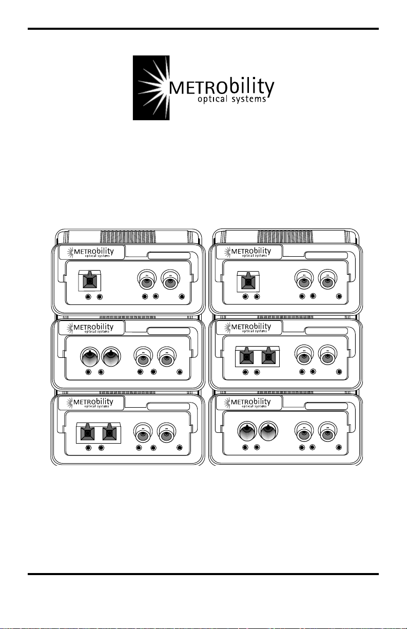
Metrobility T3/E3 Models
T3 Copper to T3 Fiber:
2115-23-01 ______T3 BNC to T3 multimode SC
2115-24-01 ______T3 BNC to T3 singlemode SC
2115-25-01 ______T3 BNC to T3 multimode ST
2115-26-01 ______T3 BNC to T3 singlemode ST
2115-27-01 ______T3 BNC to T3 singlemode SC (40km)
2115-2J-01 ______T3 BNC to T3 singlemode SC (100km)
2115-2X-01 ______T3 BNC to T3 singlemode 1550/1310nm bidirectional wavelength
2115-2Y-01 ______T3 BNC to T3 singlemode 1310/1550nm BWDM SC
E3 Copper to E3 Fiber:
2175-23-01 ______E3 BNC to E3 multimode SC
2175-24-01 ______E3 BNC to E3 singlemode SC
2175-25-01 ______E3 BNC to E3 multimode ST
2175-26-01 ______E3 BNC to E3 singlemode ST
2175-27-01 ______E3 BNC to E3 singlemode SC (40km)
2175-2J-01 ______E3 BNC to E3 singlemode SC (100km)
2175-2X-01 ______E3 BNC to E3 singlemode 1550/1310nm BWDM SC
2175-2Y-01 ______E3 BNC to E3 singlemode 1310/1550nm BWDM SC
division multiplexed (BWDM) SC
This publication is protected by the copyright laws of the United States and other countries, with all rights
reserved. No part of this publication may be reproduced, stored in a retrieval system, translated, transcribed,
or transmitted, in any form, or by any means manual, electric, electronic, electromagnetic, mechanical,
chemical, optical or otherwise, without prior explicit written permission of Metrobility Optical Systems, Inc.
© 2002 Metrobility Optical Systems, Inc. All rights reserved. Printed in USA.

Table of Contents
Metrobility T3/E3 “twister” Installation & User Guide
Overview...................................................................................................................... 4
Installation Guide ....................................................................................................... 5
STEP 1: Unpack the Media Converter and Accessories ............................... 5
STEP 2: Choose an Appropriate Location .................................................... 5
STEP 3: Set the Switches .............................................................................. 6
STEP 4: Connect to the Network .................................................................. 7
STEP 5: Apply Power ................................................................................... 8
User Guide ................................................................................................................ 11
LED Indicators ............................................................................................ 11
Theory of Operation.................................................................................... 12
Link Loss Indications .................................................................................. 14
Loopback Modes ......................................................................................... 16
Topology Solutions ..................................................................................... 18
Technical Specifications.............................................................................. 19
Acronyms and Abbreviations...................................................................... 21
Product Safety, EMC and Compliance Statements ..................................... 22
Warranty and Servicing............................................................................... 23
Metrobility Optical Systems, the Metrobility Optical Systems logo and “twister” are tradmarks of Metrobility
Optical Systems, Inc. All others are trademarks of their respective owners.
The information contained in this document is assumed to be correct and current. The manufacturer is not
responsible for errors or omissions and reserves the right to change specifications at any time without notice.

Overview
Thank you for choosing the Metrobility T3/E3 media converter.
The T3/E3 media converter from Metrobility Optical Systems provides high-speed
integration and conversion of T3 (44.736Mpbs) or E3 (34.368Mbps) coaxial telco
communication lines to fiber transport environments. The copper data stream is
converted to optical signals for greater noise immunity and longer transmission. The
T3/E3 model supports remote fiber optic links up to 2km over multimode and up to
100km over singlemode cable.
To optimize your T3/E3 network, this plug-and-play media converter operates
seamlessly with low jitter. All signal activity is completely converted ensuring
accurate communication within connected segments. The Metrobility T3 model
features a user-selectable line build out, and all T3 and E3 models include
independent copper and fiber loopback modes to isolate problems within a specific
segment of the network.
The Metrobility T3/E3 media converter offers the following key features:
• B3ZS (T3) or HDB3 (E3) line code support on the coaxial interface.
• System and port LEDs on the front panel for easy visual diagnostics.
• Independent copper and fiber loopback modes.
• User-selectable line build out for short or long haul operation on the T3
models.
• Coaxial to multimode conversion up to 2km, coaxial to singlemode conversion up to 100km, or coaxial to bidirectional wavelength division multiplexed (BWDM) conversion up to 20km.
• Surge protection on the RX and TX ports of the coaxial interface.
• Low jitter for maximum transmission quality.
• Independent clocking on the RX and TX ports.
• High MTBF.
4 Overview

Installation Guide
Follow the simple steps outlined in this section to install and start using your
Metrobility T3/E3 media converter.
Unpack the Media Converter and Accessories
Check that the following components have been included with your order:
1
2
• Metrobility T3/E3 media converter
• Power supply
• Power supply cord
• Four (4) rubber feet
Your order has been provided with the safest possible packaging, but
shipping damage does occasionally occur. Inspect your order carefully. If
you discover any shipping damage, notify your carrier and follow their
instructions for damage and claims. Save the original shipping carton if
return or storage of the unit is necessary.
Choose an Appropriate Location
The Metrobility media converter is intended for use in either office or
industrial environments. The unit must be located within six (6) feet of the
AC power source being used and placed as far away as possible from
electrical noise generating equipment such as copiers, electrostatic printers
and other motorized equipment. If exposed twisted-pair wiring is used
nearby, the wiring should be routed as far away as possible from power
cords and data cables to minimize interference.
The unit may be oriented in any manner which permits the user to make
physical connection to the power supply and leaves a minimum of six (6)
inches of space for proper ventilation.
TUV Compliance Note: For pluggable equipment, the socket outlet must be
installed near the equipment and be easily accessible.
Bei Geräten mit Steckanschluß muß die Steckdose nahe dem Gerät angebracht
und leicht zugänglich sein.
Metrobility T3/E3 5
3
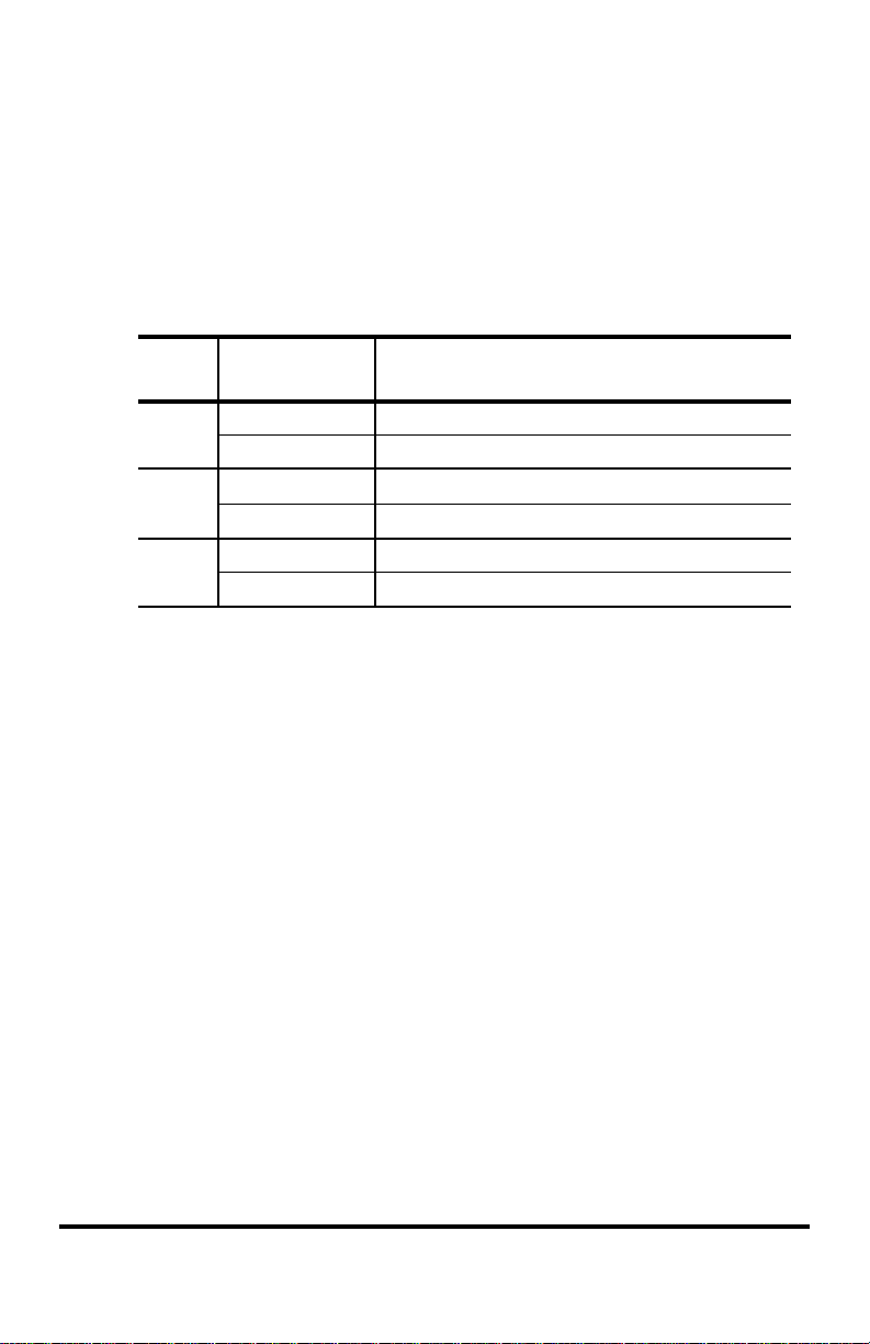
Set the Switches
A set of switches is located on the back of the unit. On the T3 models,
functional switches are clearly labeled and allow you to select from several
modes of operation. On the E3 models, only the switches labeled CLP and
FLP are functional. Unmarked switches are inoperative. Refer to the table
below for the proper setting of the switches.
hctiwS
lebaL
OBL
)ylno3T(
PLC
PLF
LBO Switch (functional only on T3 models)
Set the Line Build Out (LBO) switch down to support a long haul connection if the length of your coaxial cable is between 255 and 1200 feet. Set
LBO up to support a short haul connection if the length of your coaxial
cable is less than 255 feet. The default setting is short haul.
CLP Switch
The Copper Loopback (CLP) switch enables/disables loopback on the
copper port. When copper loopback is enabled, the incoming data and clock
are looped from the RX copper port to the TX copper port, thus returning
the copper input back to the sending device. At the same time, the data is
transmitted to the remote T3/E3 unit. However, data from the remote unit is
ignored. Loopback is disabled by default. For more information, refer to
“Loopback Modes” in the User Guide section of this manual.
noitisoPnoitcnuF
NO.)tf0021-552(tuOdliuBeniLluahgnoL
FFO )tluafed( .)tf552-0(tuOdliuBeniLluahtrohS
NO.tropreppocehtnodelbanesikcabpooL
FFO )tluafed( .noitarepolamron;delbasidsikcabpoolreppoC
NO.tropcitporebifehtnodelbanesikcabpooL
FFO )tluafed( .noitarepolamron;delbasidsikcabpoolcitporebiF
FLP Switch
The Fiber Loopback (FLP) switch enables/disables loopback on the fiber
optic port. When fiber loopback is enabled, the incoming data and clock are
looped from the RX fiber port to the TX fiber port. The data is also transmitted to the copper port, however, data from the copper port is ignored.
Loopback is disabled by default. For more information, refer to “Loopback
Modes” in the User Guide section of this manual.
6 Installation Guide
4
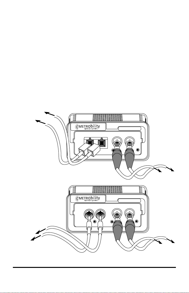
Connect to the Network
The Metrobility T3/E3 model offers the ease of plug-and-play installation.
Once power is applied to the unit, correct connectivity can be verified via
the link (LK) LED.
To connect to the network, insert the cables into the appropriate connectors
as illustrated below.
When making network connections, make sure that the receive (RX) port on
the unit connects to the transmit (TX) port of the connected device, and
make sure that the receive port of the connected device connects to the
transmit port of the Metrobility model.
T3-FX T3-TX
SM
LK
E3-FX
SM
LK
RX
LK
RXTX
LBK
“twister”™ 2115
RX
LBK
LK
“twister”™ 2175
E3-TX
RX
LBK
LK
TX
TX
MAN
PWR
PWR
Metrobility T3/E3 7
Coaxial Interface
The coaxial interface provides two BNC connectors. The receive port is
labeled RX and the transmit port is labeled TX. Each connector supports a
maximum segment length of 1200 feet. Use only RG-58 cables.
Fiber Optic Interface
2115-23-01, 2115-25-01, 2175-23-01 and 2175-25-01: The fiber optic
multimode (MM) interface supports a maximum segment length of 2km for
remote links.
2115-24-01, 2115-26-01, 2175-24-01 and 2175-26-01: The singlemode
(SM) connector supports a maximum segment length of 15km.
2115-27-01 and 2175-27-01: The singlemode long haul interface supports a
maximum segment of 40km.
2115-2J-01 and 2175-2J-01: The singlemode extended long haul interface
supports a maximum segment length of 100km.
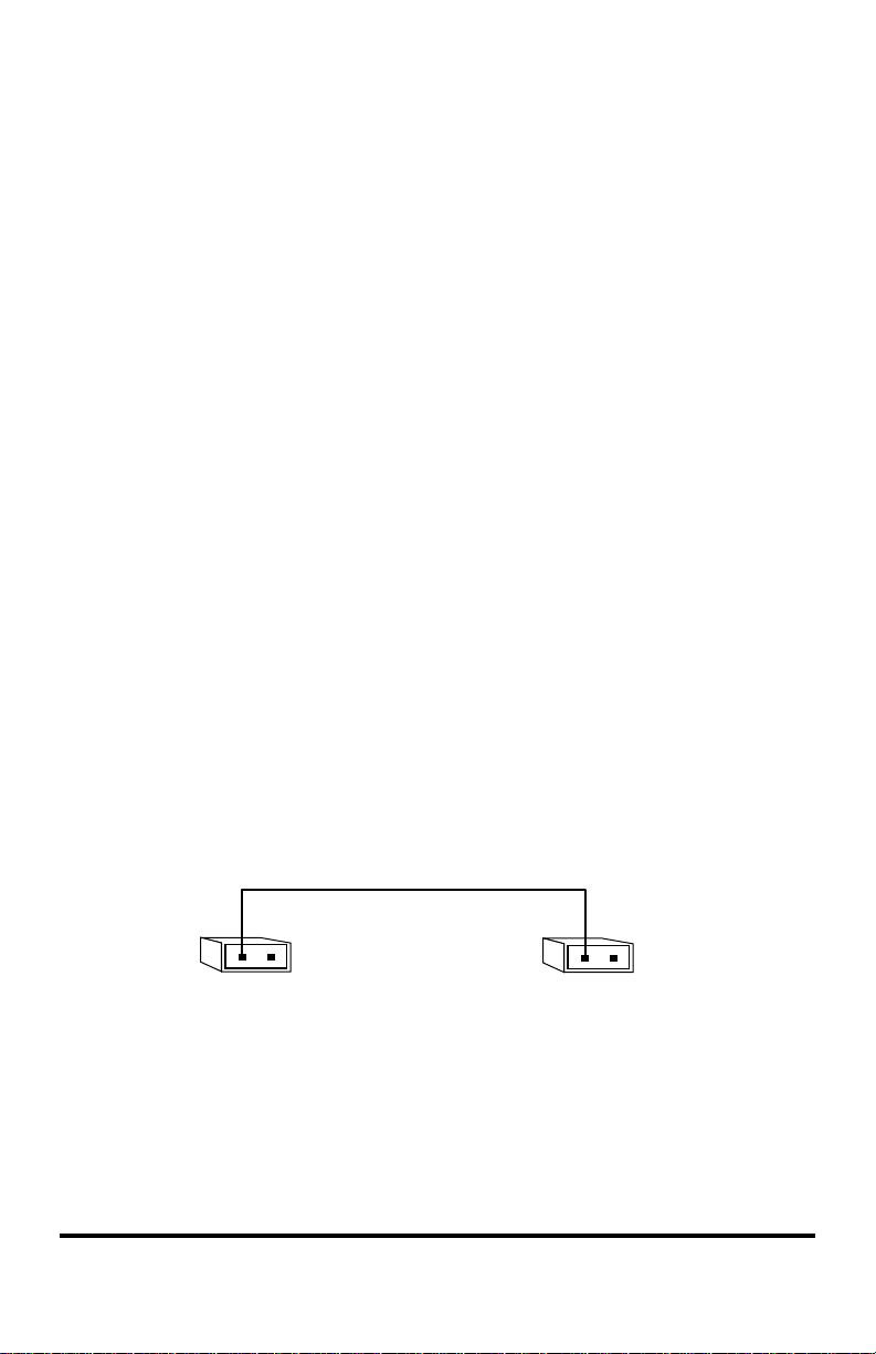
BWDM Interface
The 2115-2X-01, 2115-2Y-01, 2175-2X-01 and 2175-2Y-01 provide one
bidirectional wavelength division multiplexed (BWDM) SC connector
which supports a maximum segment length of up to 20km for remote links.
BWDM units must always be used in complementary pairs. That is, a-2X
model must be connected to a -2Y. The -2X unit is designed to transmit data
at a wavelength of 1550nm and receive at 1310nm. Correspondingly, the
-2Y unit transmits data at 1310nm and receives at 1550nm.
Metrobility
-2X Model
8 Installation Guide
up to 20km
Metrobility
-2Y Model
 Loading...