

2105-13-01,2105-14-01,2105-15-01,2105-16-01,2105-17-01,2105-1J-01,2165-13-01,2165-14-01,2165-15-01,2165-16-01,2165-17-01,2165-1J-01
Metrobility 2105-13-01,2105-14-01,2105-15-01,2105-16-01,2105-17-01,2105-1J-01,2165-13-01,2165-14-01,2165-15-01,2165-16-01,2165-17-01,2165-1J-01 User guide
T1/E1 “twister”
™
T1-FX T1-TX
RX
TX
LBK LK
MM
LBK
LKRX RX
“twister”
T1-FX T1-TX
RX
TX
LBK LK RX LKLBK RX
SM
“twister”
PWR
PWR
MAN
™
MAN
2105
2105
E1-FX E1-TX
RX
TX
LBK LK RX
MM
E1-FX E1-TX
RX
TX
LBK LK RXLKLBK RX
SM
Installation & User Guide
Models:2105-13-01 / 2105-14-01 / 2105-15-01 / 2105-16-01 /
2105-17-01 / 2105-1J-01 / 2165-13-01 / 2165-14-01 /
2165-15-01 / 2165-16-01 / 2165-17-01 / 2165-1J-01
“twister”
PWR
LKLBK RX
“twister”
PWR
™
MAN
™
MAN
2165
2165

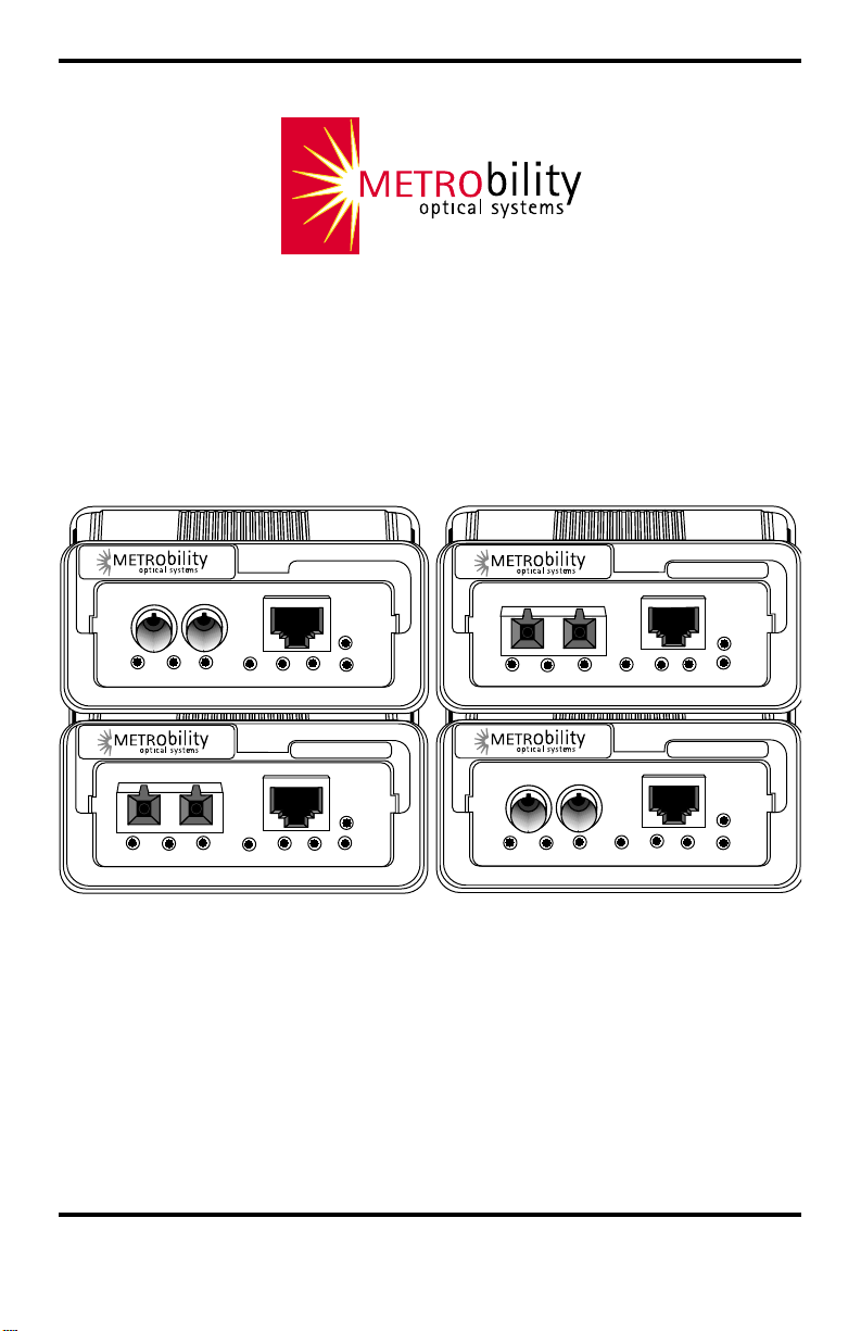
Metrobility T1/E1 Standalone Models
T1 Copper to T1 Fiber:
2105-13-01 ______T1 RJ-45 to T1 multimode SC
2105-14-01 ______T1 RJ-45 to T1 singlemode SC
2105-15-01 ______T1 RJ-45 to T1 multimode ST
2105-16-01 ______T1 RJ-45 to T1 singlemode ST
2105-17-01 ______T1 RJ-45 to T1 singlemode SC (40km)
2105-1J-01 ______T1 RJ-45 to T1 singlemode SC (100km)
E1 Copper to E1 Fiber:
2165-13-01 ______E1 RJ-45 to E1 multimode SC
2165-14-01 ______E1 RJ-45 to E1 singlemode SC
2165-15-01 ______E1 RJ-45 to E1 multimode ST
2165-16-01 ______E1 RJ-45 to E1 singlemode ST
2165-17-01 ______E1 RJ-45 to E1 singlemode SC (40km)
2165-1J-01 ______E1 RJ-45 to E1 singlemode SC (100km)
This publication is protected by the copyright laws of the United States and other countries, with all rights
reserved. No part of this publication may be reproduced, stored in a retrieval system, translated, transcribed,
or transmitted, in any form, or by any means manual, electric, electronic, electromagnetic, mechanical,
chemical, optical or otherwise, without prior explicit written permission of Metrobility Optical Systems, Inc.
© 2003 Metrobility Optical Systems, Inc. All rights reserved. Printed in USA.

Table of Contents
Metrobility T1/E1 “twister” Installation & User Guide
Overview......................................................................................................................4
Installation Guide ....................................................................................................... 5
STEP 1: Unpack the Media Converter and Accessories ...................................... 5
STEP 2: Choose an Appropriate Location ........................................................... 5
STEP 3: Set the Switches ..................................................................................... 6
STEP 4: Attach the Adapters ................................................................................8
STEP 5: Connect to the Network .........................................................................9
STEP 6: Apply Power......................................................................................... 10
User Guide ................................................................................................................12
LED Indicators ................................................................................................... 12
Factory Settings..................................................................................................14
Theory of Operation ........................................................................................... 15
Link Loss Indications ......................................................................................... 16
Diagnostic Modes............................................................................................... 18
Topology Solutions ............................................................................................ 20
Technical Specifications .....................................................................................21
Acronyms and Abbreviations.............................................................................23
Product Safety, EMC and Compliance Statements ............................................ 24
Warranty and Servicing ...................................................................................... 25
Lancast is a registered trademark; Metrobility Optical Systems, the Metrobility Optical Systems logo, and
“twister” are trademarks of Metrobility Optical Systems, Inc. All others are trademarks of their respective
owners.
The information contained in this document is assumed to be correct and current. The manufacturer is not
responsible for errors or omissions and reserves the right to change specifications at any time without notice.

Overview
Thank you for choosing the Metrobility T1/E1 media converter.
The T1/E1 media converter from Metrobility Optical Systems provides high-speed
integration and conversion of T1 (1.544Mbps) or E1 (2.048Mbps) serial copper telco
communication lines to fiber transport environments. Regardless of the line codes or
framing, the copper data stream is converted to optical signals for greater noise
immunity and longer transmission. The T1/E1 model supports remote fiber optic
links up to 2km over multimode and up to 100km over singlemode cable.
To optimize your T1/E1 network, this compact media converter operates seamlessly
with a low bit delay. All signal activity is completely converted ensuring accurate
communication within connected segments. The Metrobility T1/E1 converter is
totally frame and data independent and features user-selectable line build out.
For testing a full-duplex fiber optic link, the T1/E1 model is designed with a built-in
Bit Error Rate Test (BERT) and a dual-port loopback switch which, when enabled,
returns the incoming copper and fiber data back to the sending devices. The T1/E1
model also includes eight LEDs on the front panel for visible status reporting.
The Metrobility T1/E1 media converter offers the following key features:
• AMI or B8ZS (T1) / HDB3 (E1) bipolar line code support on the copper
interface.
• Eight LED indicators on the front panel for easy visual diagnostics.
• Built-in BERT 511.
• Dual-port loopback testing without the need for special equipment.
• Variable line length selection to set the proper T1/E1 pulse shape.
• MDI-II to MDI-X switch on the copper interface to eliminate the need for
crossover cables.
• Copper to multimode conversion up to 2km, or copper to singlemode
conversion up to 100km.
• Far End Fault notification of a loss on the remote unit’s fiber optic receiver.
• Low jitter for maximum transmission quality.
• Low power consumption (≤ 3W).
4 Introduction

Installation Guide
Follow the simple steps outlined in this section to install and start using your
Metrobility T1/E1 media converter.
Unpack the Media Converter and Accessories
Check that the following components have been included with your order:
1
2
• Metrobility T1/E1 media converter
• Power supply
• Power cord
• Four (4) rubber feet
• Two (2) SC-to-ST adapters (2105-16-01 and 2165-16-01 only)
Your order has been provided with the safest possible packaging, but
shipping damage does occasionally occur. Inspect your order carefully. If
you discover any shipping damage, notify your carrier and follow their
instructions for damage and claims. Save the original shipping carton in
case return or storage of the unit is necessary.
Choose an Appropriate Location
The Metrobility media converter is intended for use in either office or
industrial environments. The unit must be located within six (6) feet of the
AC power source being used and placed as far away as possible from
electrical noise generating equipment such as copiers, electrostatic printers
and other motorized equipment. If exposed twisted-pair wiring is used
nearby, the wiring should be routed as far away as possible from power
cords and data cables to minimize interference.
The unit may be oriented in any manner which permits the user to make
physical connection to the power supply and leaves a minimum of six (6)
inches of space for proper ventilation.
TUV Compliance Note: For pluggable equipment, the socket outlet must be
installed near the equipment and be easily accessible.
Bei Geräten mit Steckanschluß muß die Steckdose nahe dem Gerät angebracht
und leicht zugänglich sein.
Metrobility T1/E1 5
3
Set the Switches
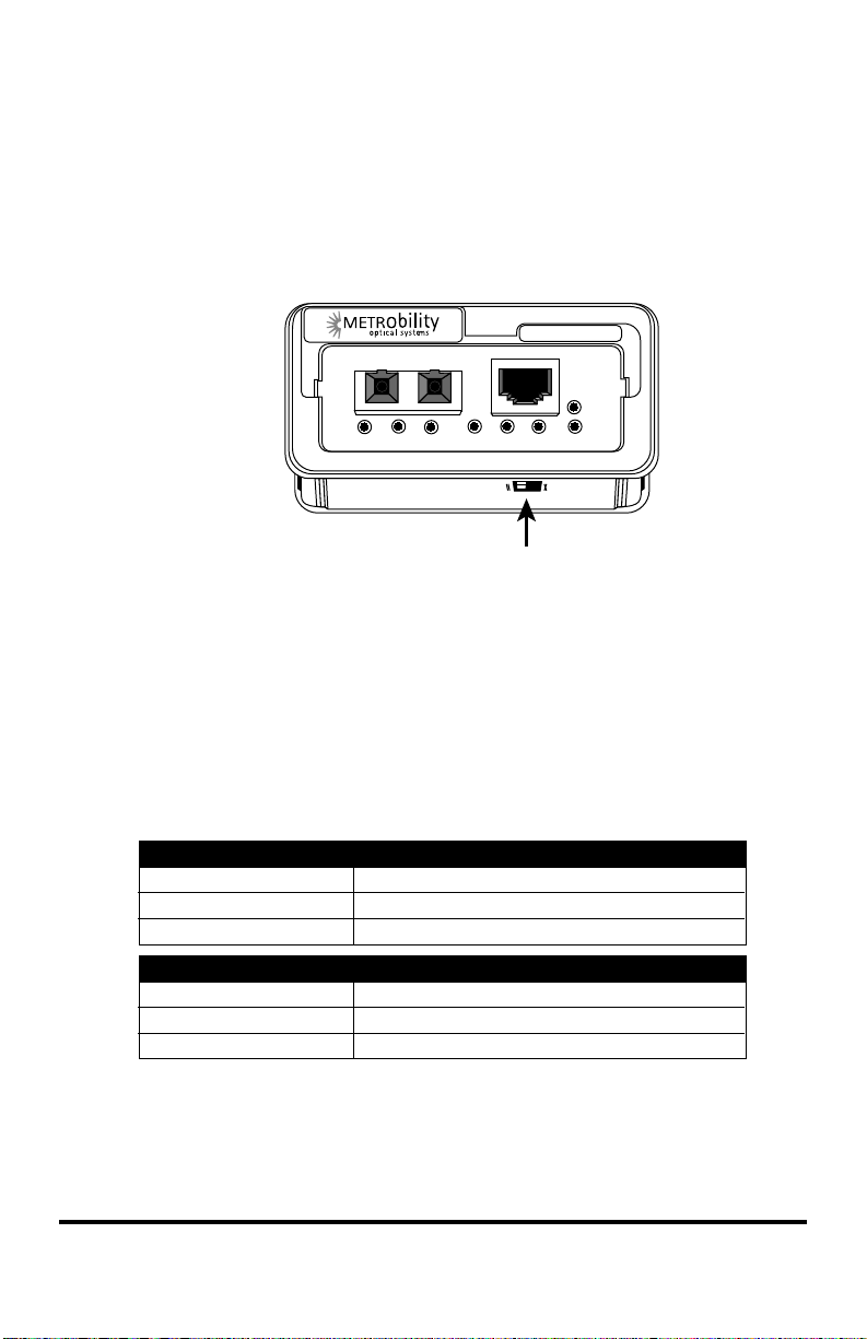
MDI-II/MDI-X Switch
To eliminate the need for crossover cables, the T1/E1 converter features an
MDI-II/MDI-X switch for the copper interface. The switch is located on the
bottom of the unit directly below the RJ-45 connector.
™
“twister”
T1-FX
TX
RX
LBK RX
RXLK LKLBK
SM
T1-TX
MDI-II / MDI-X Switch
Using a pointed object, simply slide the switch in the direction of the
appropriate symbol to configure the port for either a straight-through or
crossover connection.
• The parallel symbol (II) indicates a straight-through or parallel connec-
tion. (default)
• The cross symbol (X) indicates a crossover connection.
2105
PWR
MAN
Use the following table as a guide.
A device that is wired straight through needs one crossover connection:
If the cable is
straight through
crossover
A device that is wired crossover needs a parallel connection:
If the cable is
straight through
crossover
6 Installation Guide
the MDI-II to MDI-X switch setting should be
X
II
the MDI-II to MDI-X switch setting should be
II
X

DIP Switches
A set of six DIP switches is located on the back of the unit. These switches
allow you to select from several modes of operation as well as to set the
transmitter’s output pulse shape. Refer to the table below for the proper
setting of the DIP switches.
NOTE: The switch is ON when it is in the DOWN position.
The switch is OFF when it is in the UP position.
hctiwS
.oN
1RB
2BL
3DC
42L
51L
60L
hctiwS
lebaL
NO
FFO
noitisoPnoitcnuF
NO.delbanesi)TREB(tseTetaRrorrEtiB
FFO
FFO
FFO
FFO
FFO
)tluafed(
NO
)tluafed(
NO
)tluafed(
NOsi2tibhtgneleniL 1.
)tluafed(
NOsi1tibhtgneleniL 1.
)tluafed(
)tluafed1E(
)tluafed1T(
.stroprebif
.noitarepolamron;delbasidsiTREB
dnareppocehtnodelbanesikcabpooL
.noitarepolamron;delbasidsikcabpooL
gnidocenil)IMA(noisrevnIkraMetanretlA
.atadgnittimsnartdnagniviecerrofdesusi
signidocenil)1E(3BDHro)1T(SZ8B
.atadgnittimsnartdnagniviecerrofdesu
si2tibhtgneleniL 0.
si1tibhtgneleniL 0.
si0tibhtgneleniL 1.
si0tibhtgneleniL 0.
BR Switch
Use the Bit Error Rate Test switch to test the fiber optic connection between
two T1/E1 units. If BERT 511 is enabled on the local unit, it will generate a
511 pattern on the data channel and request temporary loopback on the
management channel. The remote unit will then put itself into loopback on
the fiber port and return the BERT data back to the local unit. The default
state of the BERT switch is disabled (OFF).
LB Switch
The LB switch enables local loopback which isolates the copper side from
the fiber side. This allows the incoming data on each side to loop back on
their own media line and return to their sending devices. The default state of
Metrobility T1/E1 7
the local loopback switch is disabled (OFF). For more information, refer to
Diagnostic Modes in the User Guide section of this manual.
CD Switch
The line code switch determines whether AMI or B8ZS / HDB3 coding is
used for receiving and transmitting data. The default setting is B8ZS for a
T1 model and HDB3 for an E1 model. These are the settings used in most
applications. AMI (bipolar) coding is common in some legacy applications.
L2, L1 and L0 Switches
These switches determine the shape of the transmitter’s output pulse. The
default is 0, 0, 0 for T1 and 0, 0, 1 for E1. (0 = OFF; 1 = ON)
2L1L0LtuOdliuBeniL1TtuOdliuBeniL1E
000
001 )tf662-331(1-XSD
010 )tf993-662(1-XSD
011 )tf335-993(1-XSD
100 )tf556-335(1-XSD
10 1 USCBd5.7110 USCBd51-
)tluafed1T(
USCBd0/)tf331-0(1-XSD
lamronsmho021
)tluafed1E(
111 USCBd5.22-
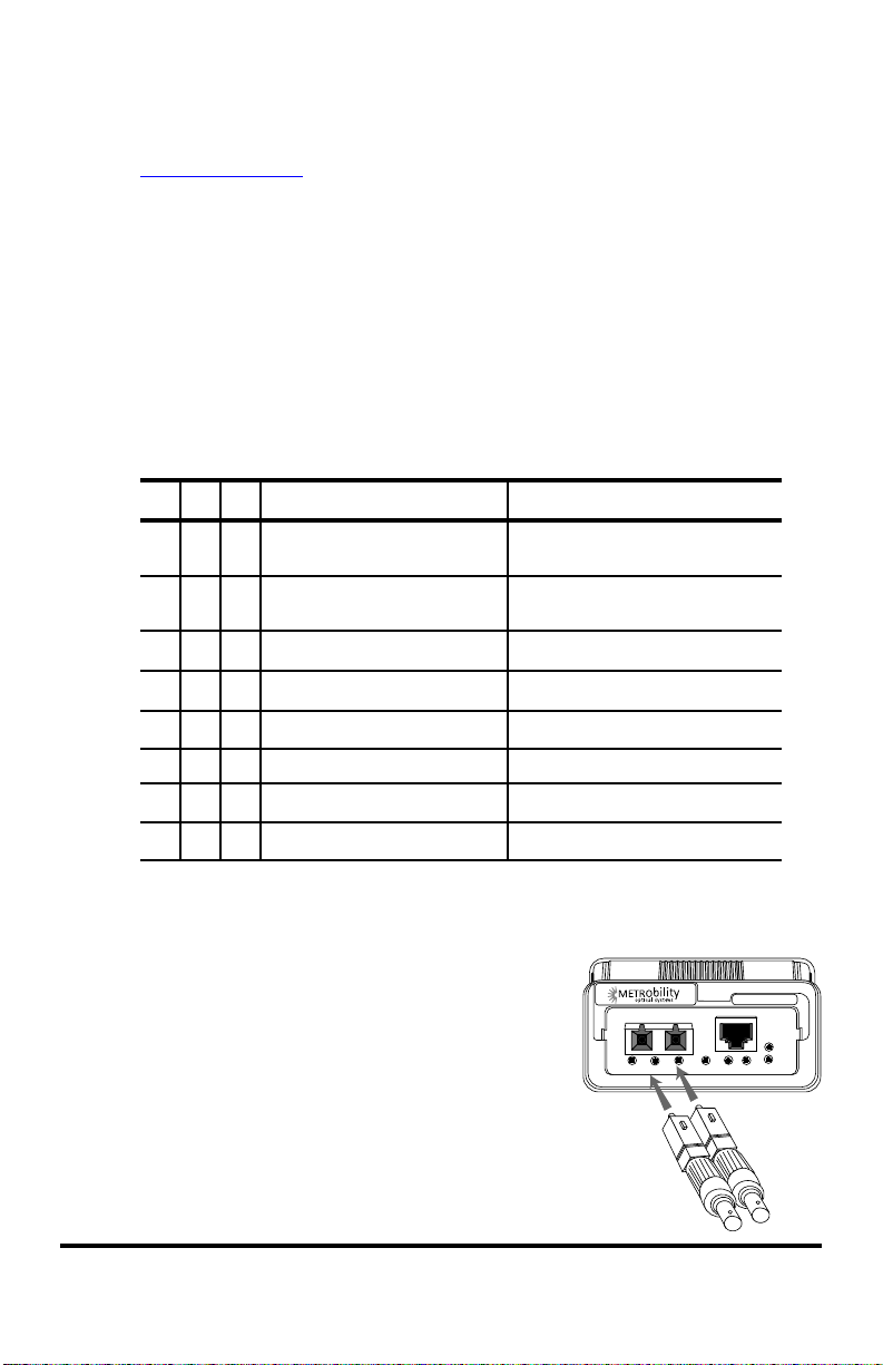
Attach the Adapters
(2105-16-01, 2165-16-01 Only)
4
The fiber ports on these models are equipped
with SC connectors and require two SC-to-ST
adapters, which are included in your order.
To connect the adapters to the Metrobility T1/E1
converter, first remove the protective coverings from
both ends of the adapters. Next, insert the SC ends of
the adapters into the SC connectors on the converter. The
unit is now ready to be connected to the network.
8 Installation Guide
E1-FX E1-TX
RX
TX
MM
“twister”
LKLBK RX
™
2165
PWR
MANLBK LK RX
 Loading...