

Page 1
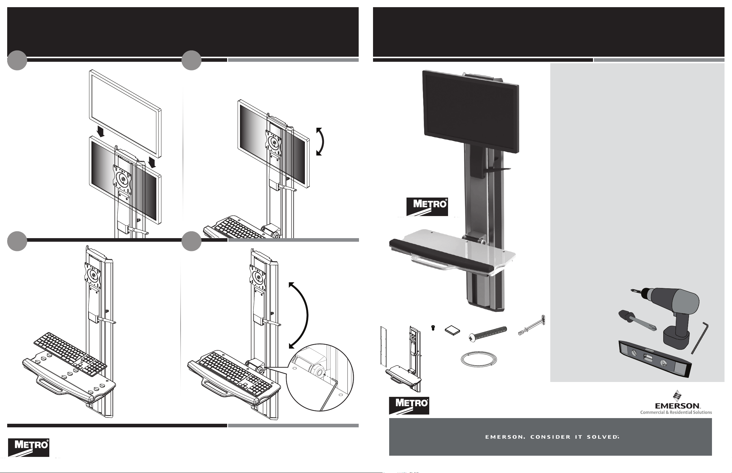
4.1 4.2
OO LS RE QUIRED
Slide the
monitor onto
the vesa plate
until the quick
connect snaps
into place
Monitor mount
allows for 90° vesa
rotation
INSTALLATION INSTRUCTIONS
MetroMount™ Slimline (WMF-SL02)
INSTALLATION WARNINGS:
Read the entire instruction sheet before you begin
installation or assembly. Installer must verify that the wall
will safely support the combined weight of all the attached
equipment and hardware. Improper installation of this
product can cause extensive property damage or serious
personal injury, either during or after the installation. It is the
responsibility of the installer to ensure that all applications
including wood, concrete, block, brick, steel, etc. are secured
properly to code. California installations could require
specic anchorage, and additional mounting screws. Check
with local authorities for codes in your area. Other seismic
states have similar regulations.
WARNING:
Max load 30 lbs of applied equipment including but not
limited to: LCD, keyboard, mouse, cabling and peripherals.
Ax the six (6)
velcro hook and
loops to the
keyboard tray
Position and
press the
keyboard onto
the tray
5.15.0
Actuate lever
for height
adjustment
Tighten or loosen
set screws on
both sides to
disable auto-
retract feature
PARTS INCLUDED
Wall Mount Console Screw Pad
Mouse cable
manager
Pan Head Screw
Toggler
DISCLAIMER:
The Manufacturer and/or Distributor will bear no
responsibility for any damages of any kind arising from
any improper installation of this product. Because wall
construction varies widely and the ultimate method of
mounting is out of the Manufacturers or Distributors
control, it is imperative that the installer consult with local
engineering, architectural, or construction personal to
ensure the wall is constructed properly and to code to
handle the applied load.
TOOLS
REQUIRED
InterMetro Industries Corporation
651 North Washington Street
Wilkes-Barre, PA 18705
www.metro.com
LO7-107
Page 2
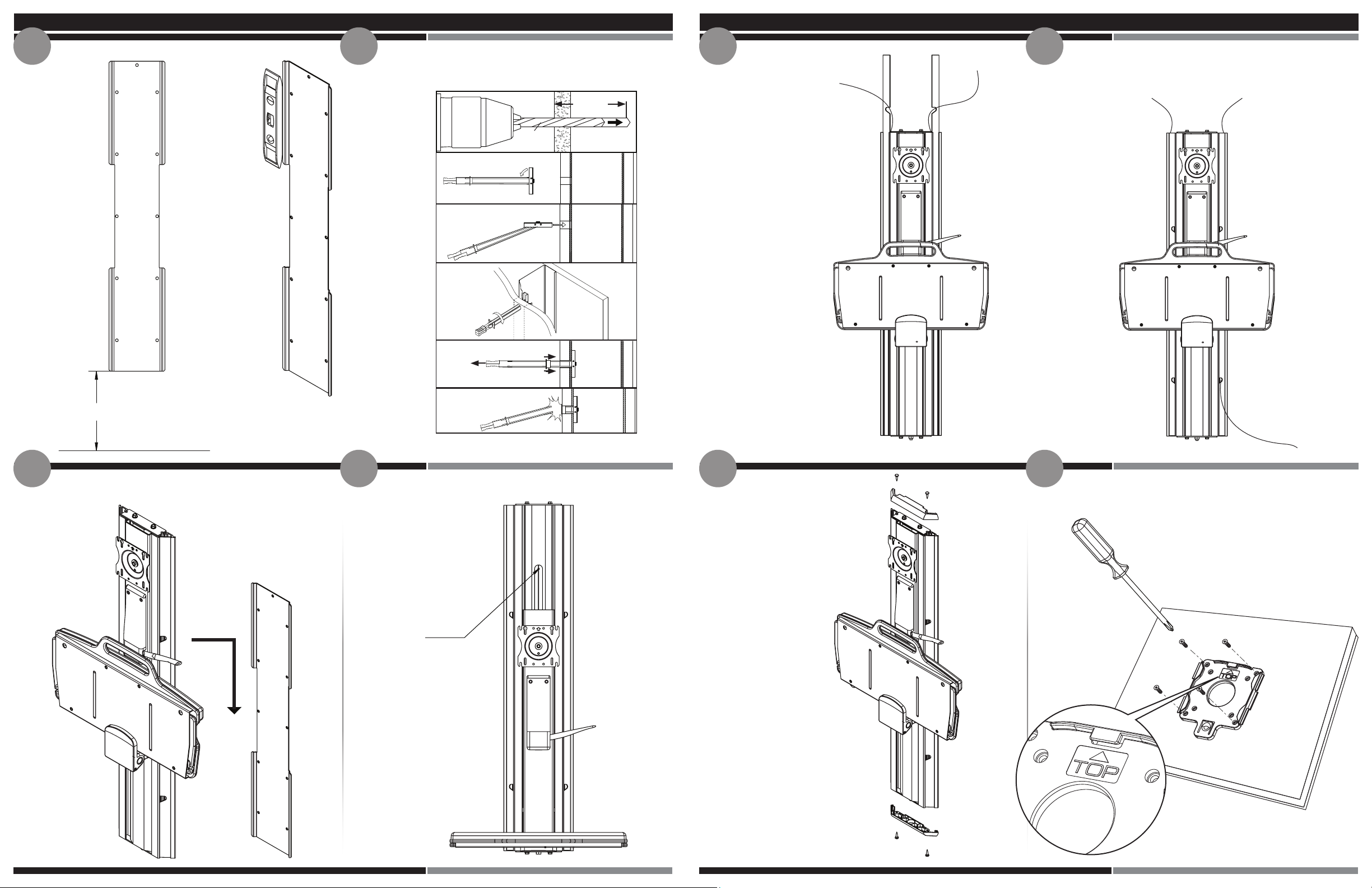
1.0 3.01.1
3.1
Measure
44” from
the oor
to the
bottom of
the wall
plate
44”
Level
wall
plate,
install
using
screws or
toggler
bolts
provided
Utilize the provided
cable management wrap
to bundle the wires
Cables can exit the top
or the bottom of the
mount
Holding the wires behind
the cable management
cover, slide the
cables into the
slot leaving
approximately
13-15” of slack
(for optimal height
adjustment)
Floor
Align the mount over
the track, then slide it
down the wall plate
until the Fusion stops
sliding
Secure the mount to
the wall plate with the
screw provided
Insert and
tighten screw
Attach the plastic
end caps to the top
and bottom of the
mount with the
screws provided
4.03.22.01.2
Attach the quick connect bracket
to the back of the monitor with the
screws provided
 Loading...