


Metro MSA-LA60 Parts List
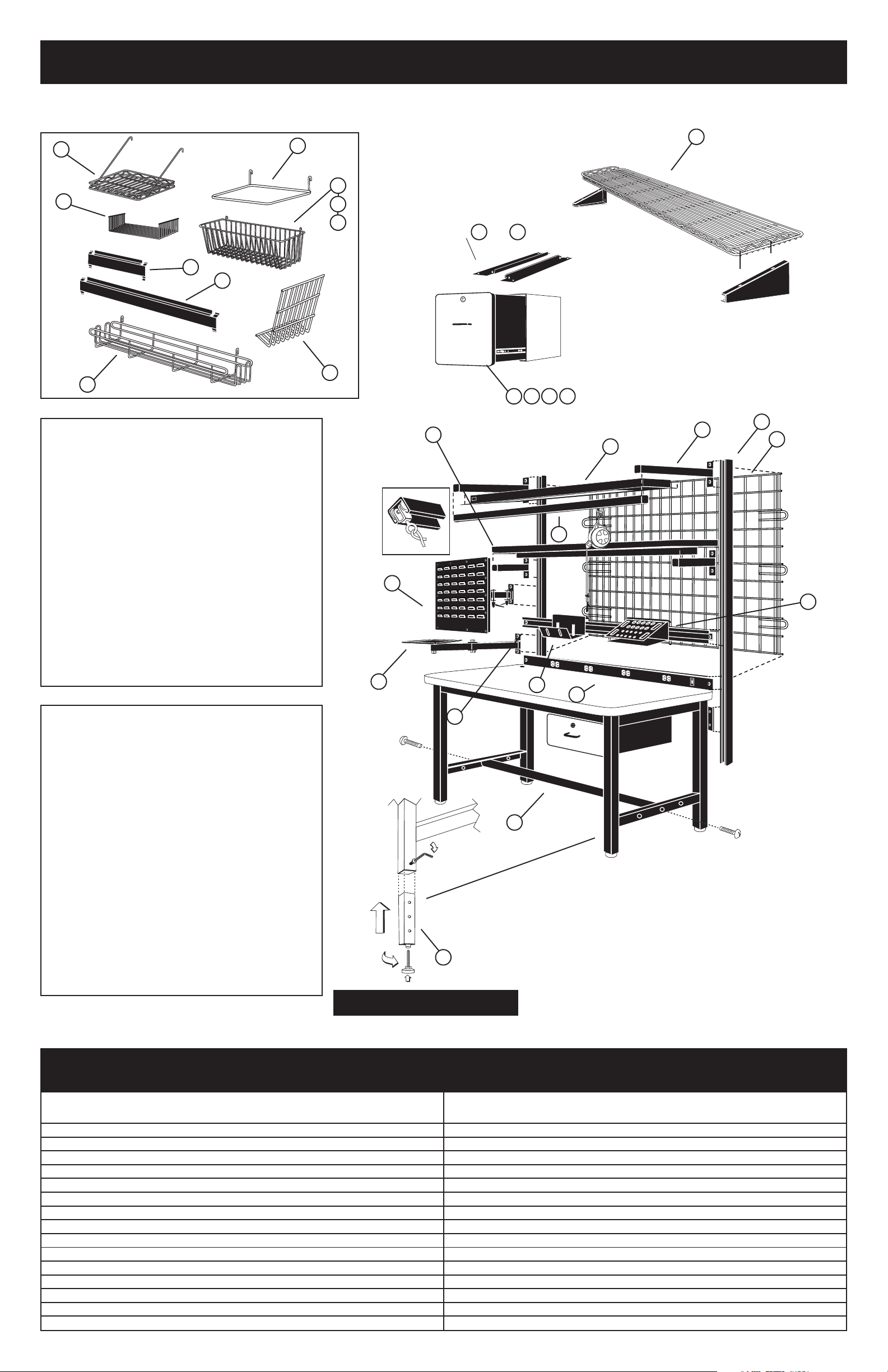
I. EXPLODED VIEW — PARTS AND ACCESSORIES GUIDE
ASSEMBLY TIP: Two (2) Allen wrenches are provided for bench assembly. However, a Ball-Socket Allen wrench will
shorten assembly time should you have access to one.
10
▼
12
▼
19
▼
▼
14
15
16
MOUNTING CHANNELS INCLUDED
5 6
WITH AND ONLY
2
▼
▼
▼
13
17
18
▼
Weight Capacities
Work Surfaces
1,000 lb. (453kg) evenly distributed
Cantilevered Shelves
100 lb. (45kg) evenly distributed weight
MSA-SMH Monitor Holder
45 lb. (21kg) evenly distributed weight
▼
▼
▼
11
5 6 7 8
3
1
▼
▼
26
▼
22
▼
▼
▼
23
9
▼
▼
PBA-MS Monitor Shelf
50 lb. (23kg) evenly distributed weight
6" Drawer 12" Drawer
30 lb. (14kg) 40 lb. (18.4kg)
MSA-SBH Bin Panel Holder
50 lb. (23kg) evenly distributed weight
Electrical
Specifications
LIGHT (MSA-LA60/MSA-LA72)
• UL Listing Pending
• Accepts two 48" (1220cm) 34WT8
• fluorescent bulbs
• 7 foot cord
POWER STRIP
(MSA-PS60/MSA-PS72)
• 8 outlets
• 115V, 15A, 60Hz continuous service
• Includes ON
/
• Protected by 15A circuit breaker
• 8 foot cord
(not included)
OFF switch
27
28
▼
▼
▼
25
▼
▼
20
▼
▼
▼
4
21
▼
29
24
OPTIONAL LEG EXTENDER INSTALLATION
AVAILABLE ACCESSORIES
60" 72"
KEY MODEL NO. MODEL NO. DESCRIPTION
1 MSA-LA60 MSA-LA72 Light Fixture with Mounting Arms
2 MSA-WS60 MSA-WS72 Cantilevered Shelf — Wire
3 MSA-LAM60 MSA-LAM72 Cantilevered Shelf — Laminate
4 MSA-BR60 MSA-BR72 Bin Rail
5 MSA-SDL6 MSA-SDL6 6" Drawer, Locking, Starter
6 MSA-SDL12 MSA-SDL12 12" Drawer, Locking, Starter
7 MSA-ADL6 MSA-ADL6 6" Drawer, Locking, Add-on
8 MSA-ADL12 MSA-ADL12 12" Drawer, Locking, Add-on
9 MSA-WG60 MSA-WG72 Wire Grid
10 PBA-MS PBA-MS Monitor Shelf
11 PBA-CHD PBA-CHD Catalog/File Holder
12 PBA-GSD PBA-GSD Grid Shelf
13 R24BR R24BR Utility Rack
14 H209C H209C Wire Basket
15 H210C H210C Wire Basket
KEY MODEL NO. MODEL NO. DESCRIPTION
60" 72"
16 H212C H212C Wire Basket
17 PBA-1BH PBA-1BH 11" Bin Holder
18 PBA-2BH PBA-2BH 22" Bin Holder
19 PBA-PFH PBA-PFH Hanging File Folder
20 MSA-PS60 MSA-PS72 Power Strip
21 MSA-FR60 MSA-FR72 Foot Rest
22 MSA-MARMS MSA-MARMS Overhead Mounting Arms
23 MSA-UR60 MSA-UR60 Uprights
24 MSA-TSH MSA-TSH Tool Storage Hanger
25 MSA-SSH MSA-SSH Solder Spool Holder
26 MSA-TT60 MSA TT72 Tool Track and Trolley
27 MSA-SMH MSA-SMH Swing-Arm Monitor Holder
28 MSA-SBH MSA-SBH Swing-Arm Bin Panel Holder
29 MSA-LE MSA-LE Leg Extenders (4)
Page 1
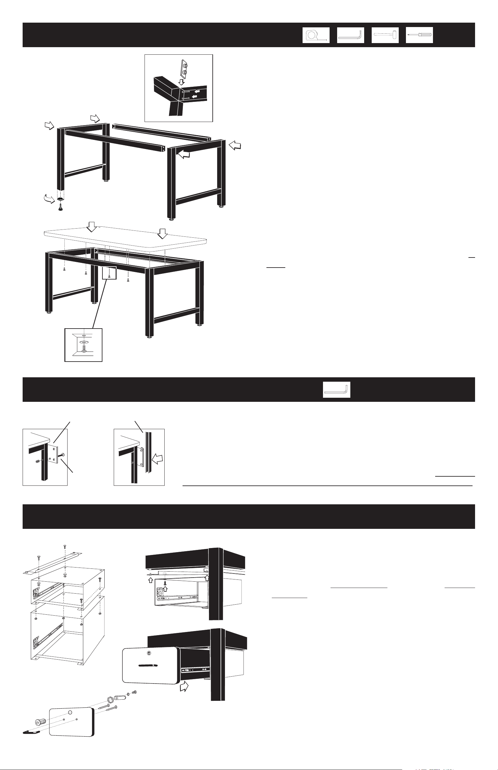
II. BASIC WORKBENCH ASSEMBLY
E
A
D
(A & B) and rails (C & D).
NOTE: Rear right and left legs of bench will have pre-
drilled hole for upright plate attachment (I) shown
below. Top side of rail will have pre-drilled holes
for mounting top.
2. Locate top of leg assemblies (A & B) and attach rails
1. Open cartons and identify the two leg assemblies
D
(C & D) to legs with bracket (E) hardware and Allen
wrench provided.
A
C
3. Install foot inserts to bottom of legs by placing them
over the legs and tapping them into position with a
B
mallet.(F) If optional leg extenders are being installed,
refer to diagram on opposite page.
F
4. Screw the leveling legs into the inserts and adjust so
that table is level.(F)
5. If installing a grounding cable to the table top, it must
G
be attached to the underside of the top prior to
installing the top. See grounding diagram on page 4.
6. Position the table top (G) so that the rear of the top is
flush with the back of the table frame and has equal
overhang on both ends. Top must be flush with back
of the table, otherwise it may interfere with upright
mounting (shown below).
7. Attach the top to the frame by inserting the wood
screws (H) through the holes in the frame assembly
and screwing them into the underside of the top (G)
in eight locations.
H
8. Make certain all bolts are securely tightened.
UPRIGHT MOUNTING INSTRUCTIONS
1. Orient the mounting plates (I) so that the short flange is facing inward
(toward the table leg) and the long flange facing away from the table.
2. Attach the plate to the table leg with the long bolt, washer, and nut.
J
3. Position the upright (J) against the mounting plate and attach to the plate
using the short bolt and rectangular nut. Follow the upright accessory
mounting instructions shown at the top of page 3.
4. The upright should always be attached using two bolts and at minimum,
it should be flush with the bottom of the mounting plate or protrude below.
▼
MOUNTING
PLATE
I
▼
FLANGE
UPRIGHT
▼
LONG
(See overleaf for instructions on installation of upright mounted accessories.)
OPTION: ATTACH DRAWER ASSEMBLY
1. Open carton and identify the drawer mounting
K
K
L
L
N
channels and mounting hardware.
2. Install the mounting channels (K) on the underside of
the table frame; make sure that the short vertical leg
of the channel is to the inside of the drawer on both
channels. Tighten the hardware securely.
3. Remove the drawer (M) from the drawer frame (L) by
extending the drawer on its slides and then flipping
the slide safety stop downward to allow the drawer to
be disengaged from the frame.
4. Position the drawer frame (L) below the mounting
channels (K) and mount to the channels using the
hardware provided. Tighten the hardware securely.
M
5. Attach drawer front, handle and lock to drawer.
6. Reinstall the drawer to the drawer frame.
7. To install optional add-on drawers (N), remove
drawers from frames. Bolt frames together in four
places using the hardware provided with the add-on
drawer.
Page 2