

Page 1
MX8020-001 Cable Connector Kit Manual
Manual for Trimming the Cable and Connecng the
Connector to an MX8031 Extension Cable
The Metrix MX8020-001 Cable Trimming and
Connector Kit provides an easy way to reduce
the length of an extension cable and maintain
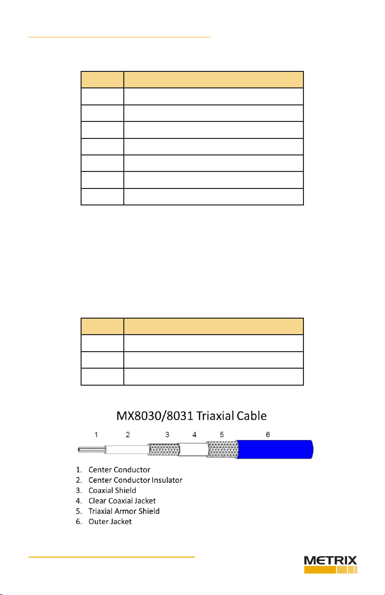
the electrical integrity of the MX8030/8031 or
MX2030/2031 Proximity Probe System. This
kit coupled with the Metrix Digital Proxim-
ity System soware provides the means for
plants, OEM’s and packagers to clean up their
cabinets and enclosures from the usual coils
of cable associated with Proximity Probe
Systems.
Part# 100951 • REV A (January 2018)
Page 2
MX8020-001 Cable Connector Kit Manual
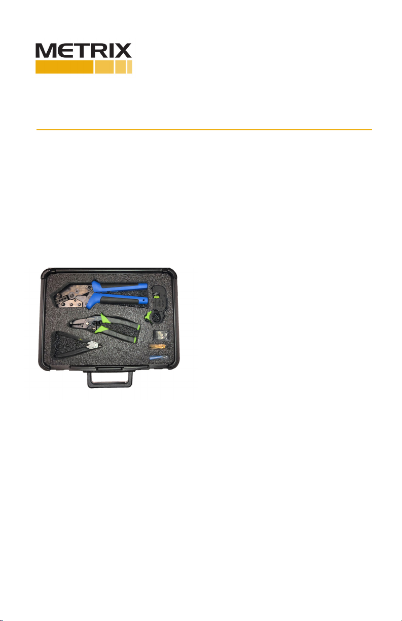
Parts Included
Quanty Descripon
1 Hand Crimping Tool
1 Crimping Tool Die for Cable Connectors
1 Triaxial Cable Cuer (Black Cartridge)
1 Wire Cuer
1 Wire Stripper
10 MX8031 Cable Connectors
10 Shrink Tubing Segments
Parts not Included, but recommended for procedure
• Needle Nose Pliers
• Heat Gun (for the Shrink Tubing)
• Safety Glasses
Accessories not included
MX8020-002 Cable Connector Rell Kit
Quanty Descripon
1 Cable Cuer Cartridge (Black)
20 MX8031 Cable Connectors
20 Shrink Tubing Segments
Part# 100951 • REV A (January 2018) Page 2 of 5
Page 3

Procedure:
1. Cut the MX8031 Triaxial Cable to the desired length using an appropriate wire cung
tool.
2. Use the Triaxial Cable Cuer with the Black Cartridge (1 acve blade) to remove
approximately 25mm (1.0”) of the outer shield of the triaxial cable. This is the most
dicult step of this process. The armor shield is very tough and rugged. Be careful with
sharp edges and bare wires. With proper blade adjustment, rotate the cuer at least
ten mes for a clean cut. Use the wire strippers to remove the triaxial shield (10 AWG,
2.6mm). A proper cut may leave the clear coaxial jacket of the coaxial cable (clear plas-
c covering) intact. Adjust the blade and tension to obtain the desired depth of cut,
you don’t want to cut through the coaxial shield so you may have to remove the clear
coaxial jacket with the wire stripping tool (14 AWG, 1.6mm).
3. Remove the clear coaxial jacket without cung into the coaxial shield using the wire
stripping tool if necessary. Put the shield ferrule over the coaxial cable shield, with the
thicker edge away from the cut (or trimmed) end. Move the ferrule down the coaxial
cable so it meets the blue triaxial cable. Slide on the blue heat shrink tubing.
Part# 100951 • REV A (January 2018) Page 3 of 5
Page 4

4. Pull back, and fan out, the wire coaxial shield to the ferrule to expose the center conductor insulator and conductor. Use the wire strippers to expose approximately 6mm
(0.25”) of the center conductor (22 AMG, 0.80mm). Gently twist the center conductor
wire, then slide the center core pin onto the center conductor wire and insulator.
6mm
12mm
6mm
5. Push the shield onto the shield side of the center core pin. Slide the ferrule onto the
center core pin to cover 30% of the back end of the center core pin. Trim o the
shield to 30% engagement on the pin. This will allow the ferrule to slide up easier and
sll maintain shield engagement. Put the wire strippers in the locked positon and use
the strippers as a dri (stop) for the pin body. This will help you with counter force to
slide the ferrule on. Do not let the center core pin slip while sliding on the ferrule. Do
not let shield wire extrude beyond the ferrule, or it will make installing the connector
dicult. Remove excess coaxial shield that will not t under the ferrule. Note: The
shield takes the cable load not the center pin conductor.
6. Crimp the center core pin, using the .041 hole, next to the connector insulaon. Use
the kit supplied die and crimping tool. Note: The crush is very light on the center pin
conductor.
Shrink Wrap
Part# 100951 • REV A (January 2018) Page 4 of 5
Page 5

7. Slide the connector onto the center core pin and ferrule. Be careful to ensure the
center core pin comes through the connector. Crimp the connector, using the .178
hexagon hole, at the ridge line. Test the connecon by pulling on the connector with
approximately 8kg (20lbs) of force. Use the hot air gun to shrink the tubing onto the
connecon.
8. Test the modied MX8031 extension cable. Ensure you have an open circuit between
the center pin and the connector case. Ensure you have connuity between the
cases at both ends of the cable. Ensure you have connuity between the pin at one
end and center conductor at the other end. If any of these checks are not true you
must do the connecon over again.
9. Ensure you program the Metrix DPS unit (MX2033 or MX2034) for the closest meter
electrical length that you now have. Verify the system is linear. Perform calibraon if
necessary. For instrucons on how to modify the Metrix DPS conguraon, from the
Factory Purchased conguraon go to the below link.
hp://www.metrixvibraon.com/tenants/metrix/documents/100545.pdf
info@metrixvibraon.com
8824 Fallbrook Dr. Houston, TX 77064, USA
Tel: 1.281.940.1802 • Fax: 1.713.559.9421
Aer Hours (CST) Technical Assistance: 1.713.452.9703
Part# 100951 • REV A (January 2018) Page 5 of 5
www.metrixvibraon.com
 Loading...