

Page 1

MX 59HD
Notice de fonctionnement
User's manual
Bedienungsanleitung
Libretto d’istruzioni
Manual de instrucciones
ENGLISH -
page 19 Chapter
II
I
Copyright © X03052A00 - Ed. 04 - 02/13
Page 2
19
20
21
22
18
17
16
15
14
5
23
9
6
8
7
10
11
12
13
1 2 3 4
Multimètre digital portable
Page 3

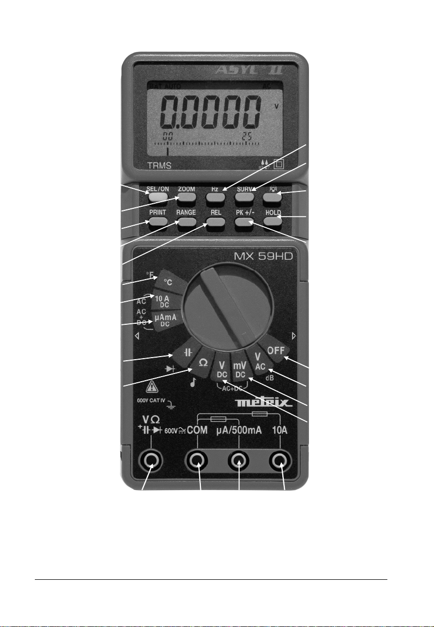
LEGENDE / CAPTION / BESCHREIBUNG / LEGENDA / LEYENDA
1 Borne d'entrée calibres 11, 12, 13, 14, 15 12 Mesure de tensions 500 mV
2 Entrée de référence du multimètre 13 Mesure de tensions continues
3 Borne d'entrée calibre µA mA 14 Mesure de résistance
4 Borne d'entrée calibre 10 A 15 Mesure de capacité
5 Mise sous tension (fonctions secondaires) 16 Mesure de courant jusqu’à 500 mA
6 Changement de gamme 17 Mesure de courant jusqu'à 10 A
7 Mesure en mode relatif 18 Mesure de température
8 Mesure de crêtes 19 Sélection des fonctions temporelles
9 Gel de l'affichage 20 Sélection consultations des valeurs de surveillance
10 Mise hors tension 21 Elargissement de l'échelle du bargraph
11 Mesure de tensions alternatives 22 Envoi de données vers l'imprimante
1 Input terminal, ranges 11, 12, 13, 14, 15 12 500 mV voltage measurement
2 Multimeter reference input 13 DC voltage measurement
3 Input terminal, range µA mA 14 Resistance measurement
4 Input terminal range 10 A 15 Capacitance measurement
5 Power on (selects secondary functions) 16 Current measurement up to 500 mA
6 Range change 17 Current measurement up to 10 A
7 Relative mode measurement 18 Temperature measurement
8 Peak measurement 19 Time functions selection
9 Display hold 20 Monitoring values selection / display
10 Power off 21 Bargraph scale magnification
11 AC voltage measurement 22 Data sending to a printer
1 Eingangsbuchse für Meßber. 11,12,13,14,15 12 Spannungsmessung bis 500 mV
2 COM-Eingangsbuchse 13 Messung von DC-Spannungen
3 Eingangsbuchse µA mA 14 Widerstandsmessung
4 Eingangsbuchse 10 A 15 Kapazitätsmessung
5 Multimeter Einschalten (+ Zweitfunktionen) 16 Strommessung bis 500 mA
6 Bereichsumschaltung 17 Strommessung bis 10 A
7 Relativ-Messung 18 Strommessung von Temperatur
8 Spitzenwertmessung 19 Zeit Funktionen Auswahl
9 Anzeige speichern 20 Auswahl / Anzeige der Messungswerte
10 Multimeter Ausschalten 21 Erweiterung des Bargraph Skalas
11 Messung von AC-Spannungen 22 Sendung von Angaben zum Drucker
23 Activation du rétro-éclairage
23 Backlighting
23 Hintergrundbeleuchtung
1 Borne de entrada calibres 11, 12, 13, 14, 15 12 Medida de tensiones 500 mV
2 Entrada de referencia del multÍmetro 13 Medida de tensiones continuas
3 Borne de entrada calibre µA mA 14 Medida de resistencias
4 Borne de entrada calibre 10 A 15 Medida de capacidades
5 Puesta en servicio (funciones segundarias) 16 Medida de corrientes hasta 500 mA
6 Cambio de calibre 17 Medida de corrientes hasta 10 A
7 Medidas relativas 18 Medida de temperaturos
8 Medidas de cresta 19 Seleccion funciones temporales
9 Memorizacion de la representacion visual 20 Seleccion de los valores de muestreo
10 Puesta fuera de servicio 21 Ampliacion de la graduation del bárgrafo
11 Medida de tensiones alternativas 22 Transmisión de los datos hacia una impresora
1 Boccola d’ingresso portate 11, 12, 13, 14, 15 12 Misura delle tensioni 500 mV
2 Ingresso di riferimento del multimetro 13 Misura delle tensioni continue
3 Boccola d’ingresso portata µA mA 14 Misura di resistenza
4 Boccola d’ingresso portata 10 A 15 Misura della capacità
5 Accensione (scelta funzioni secondarie) 16 Misura di corrente fino a 500 mA
6 Cambiamento di portata 17 Misura di corrente fino a 10 mA
7 Misura in modalità relativa 18 Misura di temperatura
8 Misura delle creste 19 Selezione di funzioni di tempo
9 Immobilizzazione della visualizzazione 20 Sorveglianza
10 Spegnimento 21 Allargare la visualizzazione del bargraph
11 Misura delle tensioni alternate 22 Invio dati verso la stampante
23 Retroiluminación
23 Retro illuminazione
Multimètre digital portable
Page 4

Chapter II
CO
NTENTS
1. GENERA
1.1. Precauti
L INSTRUCTIONS.................................................................................................................
ons and safety measures..................................................................................................20
1.2. Protection devices..........................................................................................................................21
1.3. Safety devices................................................................................................................................22
1.4. Warranty.........................................................................................................................................22
1.5. Maintenance...................................................................................................................................24
1.6. Unpacking - Repacking..................................................................................................................22
ESCRIPTION......................................................................................................................................
2. D
2.1. S
elector switch ...............................................................................................................................23
2.2. Keypad............................................................................................................................................23
2.3. Display............................................................................................................................................23
2.4. Power supply..................................................................................................................................23
2.5. Input terminals................................................................................................................................23
3. C
OMMISSIONING ................................................................................................................................
onnecting the test leads...............................................................................................................24
3.1. C
3.2. Switching on the instrument...........................................................................................................24
3.3. Switching off the instrument...........................................................................................................24
3.4. Special configurations.................................................................................................... ................24
3.5. Multimeter maintenance.................................................................................................................25
4. FUNCT
IONAL DESCRIPTION.............................................................................................................
4.1. S
EL/ON key...................................................................................................................................26
4.2. RANGE key ....................................................................................................................................29
4.3. REL key..........................................................................................................................................29
4.4. Pk +/- key........................................................................................................................................29
4.5. HOLD key.......................................................................................................................................29
4.6. ZOOM key ......................................................................................................................................29
4.7. SURV key.......................................................................................................................................30
4.8. Hz key.............................................................................................................................................30
4.9. PRINT key ......................................................................................................................................30
4.10. key ................................................................................................................
..........................30
20
23
24
26
5. T
ECHNICAL SPECIFICATIONS..........................................................................................................
C voltages....................................................................................................................................31
5.1. D
31
5.2. AC voltages (AC and AC+DC).......................................................................................................31
5.3. DC current ......................................................................................................................................32
5.4. AC currents (AC and AC+DC)........................................................................................................32
5.5. Resistance / Continuity...................................................................................................................33
5.6. Capacitance....................................................................................................................................33
5.7. Diode threshold voltage measurement ..........................................................................................34
5.8. Frequencies....................................................................................................................................34
5.9. Duty cycle %+, %- ..........................................................................................................................34
5.10. Temperature function...................................................................................................................35
5.11. dB function....................................................................................................................................35
6. GENERA
6.1. A
Portable digital multimeter 19
L SPECIFICATIONS..............................................................................................................
ccessories....................................................................................................................................37
36
Page 5

Chapter II
1. GENERAL INSTRUCTIONS
You have just acquired a portable digital multimeter and we thank you for your confidence.
This instrument complies with the specification of EN publication 61010-1, concerning safety
requirements for electronic measuring apparatus. To get the best service from this instrument,
read carefully this user's manual and respect the detailed safety precautions.
1.1. Precautions and safety measures
1.1.1. Before use
• This instrument has been designed for use indoors :
- in an environment with pollution level 2
- at an altitude of less than 2000 m
- at a temperature between 0°C and 50°C
- with relative humidity of less than 80 % up to 40°C.
• It can be used for measurements on the following types of circuits:
- Measurement category III for voltages no higher than 600 V (AC or DC)
in relation to the earth and between input terminals.
- Measurement category IV for voltages no higher than 600 V (AC or DC)
in relation to the earth and between inputs terminals.
• Definition of measurement categories :
CAT I : Measurement category I is for measurements performed on circuits not directly
connected to mains.
E.g.
CAT II
connected to the low voltage installation.
E.g.
CAT III
E.g.
CAT IV
voltage installation.
E.g.
: protected electronic circuits
: Measurement category II is for m easurem ents perform ed on circuits dir ectly
: power supply to domestic appliances and portable tools.
: Measurement category III is for measurements performed in the building installation
: machine or industrial apparatus power supply.
: Measurement category IV is for measurements performed at the sour ce of the low-
: energy inputs
∗ For your own safety, only use the measuring probes which have been delivered with
the instrument : they conform to the EN 61010-031 safety standard. Before use,
check that they are in good condition.
∗ The safety of any system incorporating this instrument is t he responsibilit y of the
system assembler.
1.1.2. During use
∗ Never exceed the protection limit values indicated in the specifications for each type
of measurement.
∗ When the multimeter is linked to measurement circuits, do not touch unused
terminals.
∗ When the scale of the value to be measured is unknown, check that the scale initially
set on the multimeter is the highest possible or, wherever possible, choose the
autoranging mode.
∗ Before changing functions, disconnect the test leads from the circuit under test.
20 Portable digital multimeter
Page 6
Chapter II
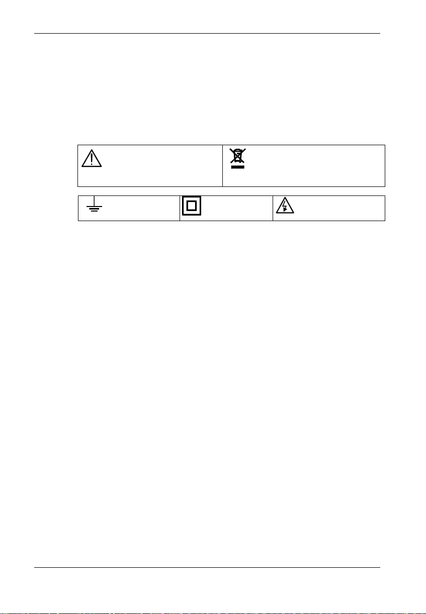
1.1.3. Symbols
∗ When performing current measurements, never change of range, do not connect or
disconnect leads without first isolating the current. If you do, there is a risk of
generating surge currents which can blow the fuses or damage the instrument.
∗ In TV repair work, or when carrying out measurements on power switching circuits,
remember that high amplitude voltage pulses at the test points can damage the
multimeter. Use of a TV filter will attenuate any such pulses.
∗ Never perform resistance, condenser and diode measurements on live circuits.
WARNING : Risk of danger.
Refer to the operating manual to
find out the nature of the potential
hazards and the action necessary
to avoid such hazards.
Earth Dual insulation
1.1.4.
Opening the instrument
∗ Before opening the instrument, always disconnect from all sources of electric current
and make sure not to be loaded with static electricity, which may destroy internal
components.
∗ Fuses must be replaced with fuses of the same rating and type.
∗ Any adjustment, maintenance or repair work carried out on the multimeter should be
carried out only by appropriately qualified personnel, after having taken into account
the instructions in this present manual. A "qualified person" is one who is familiar
with the installation, construction and operation of the equipment and the hazards
involved. He is trained and authorized to energize, de-energize circuits and
equipment in accordance with established practices.
∗ If any faults or abnormalities are observed, take the instrument out of service and
ensure that it cannot be used until it has been checked out.
∗ It is recommended to remove the battery from the instrument if not used.
1.2. Protection devices
ASYC II series instruments are fitted with various protection devices :
Selective sorting of waste for recycling
electric and electronic materials.
In accordance with the WEEE
2002/96/EC directive : must not be
treated as household waste.
DANGER :
Risk of electrical shock
Consult the manual.
∗ Varistor protection for limiting transients of over 1500 Vpk at the VΩ terminal, particularly
8 kV pulse streams as defined in French standard EN 61010-1 relative to safety.
∗ A PTC (Positive Temperature Coefficient) resistor protects against overvoltages up to
600 V during resistance, capacitance and diode measurements. This protection is reset
automatically once overload is over.
∗ Two fuses provide protection during measurements of intensity type.
∗ Maximum protection : 600 V
∗ IP protection rating of 67
Portable digital multimeter 21
Page 7

Chapter II
1.3. Safety devices
∗ The battery unit and fuses cannot be accessed without first disconnecting the measuring
leads.
∗ When measuring voltages above 24 V, the symbol blinks on the display.
∗ If the maximum range is repeatedly exceeded, an intermittent audible signal indicates the
risk of electric shock.
1.4. Warranty
1.5. Maintenance and metrological verification
1.6. Unpacking - Repacking
This equipment is warranted against any defects of manufacture or materials according to the
general conditions of sale.
During the warranty period (3 years), defective parts will be replaced, the manufacturer reserv ing
the right to repair or replace the product. In the event of the equipment being returned to the
after sale department or to a local agency, carriage to the centre shall be payable by the
customer.
The warranty does not cover the following :
1. Repairs necessitated by misuse of the equipment or use in association with incompatible
equipment.
2. Modification of the equipment or any related software without the explicit authorization of
the manufacturer.
3. Repairs necessitated by attempts to repair or maintain the product made by a person not
approved by the manufacturer.
4. Adaptation to a specific application not provided for in the specifications of the equipment or
the user manual.
5. Damage after a drop, a shock or flooding.
The contents of this manual must not be reproduced in any form whatsoever without the consent
of the manufacturer.
Return your instrument to your distributor for any work to be done within or outside the
guarantee.
This equipment has been fully checked out mechanically and electrically before shipping.
All precautions have been taken to ensure that the instrument arrives at its destination
undamaged.
However, it is advisable to carry out a rapid check for damage sustained in shipping.
If there is any evidence of damage, make this known immediately to the shipper.
* Caution Should you need to return the instrument, preferably use the original
packaging and indicate the reasons as clearly as possible on an
accompanying note.
22 Portable digital multimeter
Page 8

Chapter II
2. DESCRIPTION
This multimeter is one of the ASYC II (Advanced SafetY Concept, third generation) family,
designed for a high degree of user safety, maximum protection and a hitherto unrivalled
performance.
2.1. Selector switch
It is a standalone, handheld professional measuring instrument, capable of measuring the
following quantities (accessed by the ten-position rotary selector switch) :
∗ AC voltages with AC (or RMS) capacitive coupling,
∗ AC voltages with AC + DC (or TRMS) direct coupling,
∗ DC voltages,
∗ AC currents with AC (or RMS) capacitive coupling,
∗ AC currents with AC+DC (or TRMS) direct coupling,
∗ DC currents,
∗ resistance values,
∗ continuity (with beeper),
∗ capacitance,
∗ diode threshold voltage,
∗ frequencies,
∗ duty cycles,
∗ dBm,
∗ temperature.
2.2. Keypad
An ten-key keypad lets you :
∗ select the autoranging mode (RANGE key)
∗ freeze a value (HOLD key)
∗ measure fast peaks (Pk +/- key)
∗ set the measurement relative to a reference value (REL key)
∗ select a function derived from the main function, or switch on the multimeter again after it
has been shut down automatically (SEL/ON key)
∗ select time-domain measurements: frequency, duty cycle, (Hz key)
∗ select survey mode to detect minimum, maximum or average value (SURV key)
∗ expand the bargraph scale (ZOOM key)
∗ activate sending data to a printer (PRINT key)
∗ activate back lighting of the display unit ( key)
2.3. Display
The display shows (display backlight when required in poor lighting conditions) :
∗ clearly legible figures (14 mm high)
∗ a readout of the parameter being measured through a 34-segment bargraph
∗ perform 50 000-count measurements (high resolution)
∗ perform 5 000-count measurements (low resolution)
2.4. Power supply
It is powered by a standard 9 V battery which provides approximately 500 hours of operation.
2.5. Input terminals
Measurements are performed using two measuring leads supplied with the instrument
connected to input terminals 1, 2, 3 and 4, as indicated in §. 3.1.
Portable digital multimeter 23
Page 9

Chapter II
3. COMMISSIONING
3.1. Connecting the test leads
Connect the black lead to the COM socket (for all measurements). Depending on the position of
the selector switch, connect the red lead as follows:
3.2. Switching on the instrument
Turn the selector switch to the required function.
All segments of the display come on for a few seconds. The instrument is then ready for
measurements.
3.3. Switching off the instrument
The instrument can be switched off manually by returning the selector switch to the OFF position,
or automatically after approximately half an hour if no key is pressed or the switch is not operated.
Note Automatic shutdown of the instrument is disabled in order to avoid interrupting
)
For user safety, automatic shutdown is also disabled when a measured
(
3.4. Special configurations
To adapt the configuration of the instrument to the measurement environment, the user
can :
- Choose 50 Hz or 60 Hz rejection :
Switch on with the rotary switch while holding down the HOLD key. The selection is
reversed from the last configuration, is displayed for two seconds and remains backed up in
non-volatile memory.
- Choose the input impedance for measurements in the mV range :
Switch on with the rotary switch while holding down the RANGE key. The selection is
reversed from the last configuration, is displayed for two seconds, and remains backed up
in non-volatile memory.
- Choose a low resolution mode (5, 000 counts) :
Switch on with the rotary switch while holding down the REL key. The selection is displayed
for two seconds.
Rotary selector switch position Input terminal
VAC, mVDC, VDC, Ω, , °C VΩ
10 A 10 A
µA mA µA / 500 mA
the surveillance mode (SURV), peak measurements (Pk +/-)
or a data print-out.
magnitude (Voltage/current) present at the input exceeds dangerous levels
indicator displayed).
24 Portable digital multimeter
Page 10

Chapter II
3.5. Multimeter
3.5.1. Fuse self-test
When fuse F1 (0.63 A) or F2 (11 A) is blown, the display shows “FUSE.1” or “FUSE.2”,
accordingly.
If both fuses are blown, the display shows “FUSES”.
Replace the fuse or fuses concerned.
Note Fuse F1 cannot be tested unless the switch is set to the μA mA position.
)
3.5.2. Battery self-test
When the BAT indication appears on the display, the instrument still has approximately
50 hours of operation, but specifications can no longer be guaranteed.
Replace the battery.
3.5.3. Replacing the battery or fuses
Disconnect the cords from the measured circuit, then multimeter.
Open the multimeter casing as follows (refer to last page of the manual) :
maintenance
Fuse F2 is located in the common circuit. Therefore, all measurements become
impossible when it is out of service.
1 - Remove the stand from the back of the instrument. Figures 1 and 2
2 - Remove the front cover using the stand as a lever. Figures 3 and 4
3 - Remove the gasket.
4 - Replace the battery or fuse.
Before use, make sure that the gasket, then the front cover are carefully set back on the
instrument.
3.5.4. Cleaning
Clean the multimeter using a damp cloth. Do not use abrasives or solvents.
Portable digital multimeter 25
Page 11

Chapter II
4. FUNCT
4.1.
IONAL DESCRIPTION
SEL/ON key
This can be used to switch on the multimeter again after an automatic shutdown. It can also be
used to access secondary functions associated with the selector switch positions.
The flowcharts below define these various functions.
4.1.1. V
position
AC
AC voltage measurements
SEL/ON
dBm measurement
SEL/ON
4.1.2. mV
26 Portable digital multimeter
position
DC voltage measurement
500 mV range
SEL/ON
AC+DC voltage measurement
500 mV range
SEL/ON
Page 12

Chapter II
V
DC
position
4.1.3.
4.1.4. Ω position
DC Voltage measurement
AC+DC Voltage measurement
Resistance measurement
SEL/ON
SEL/ON
SEL/ON
Continuity test
SEL/ON
4.1.5.
Portable digital multimeter 27
position
Capacitance measurement
SEL/ON
Diode voltage measurement
SEL/ON
Page 13

Chapter II
4.1.6. µA mA / 10 A positions
DC current measurement
SEL/ON
AC current measurement
SEL/ON
AC+DC current measurement
SEL/ON
4.1.7. °C Position
Temperature measurement
SEL/ON < 1 sec. SEL/ON > 1 sec.
Connections short-
circuited
Sensor selection
Pt 100 / Pt 1000
Scale selection
°C/°F
REL
Temperature measurement
with connection resistance
compensation
°C/°F selection and Pt 100 / Pt 1000 selection are saved in non-volatile memory.
Pt 100 selection is indicated by display of Ω symbol and Pt 1000 by display of kΩ symbol.
28 Portable digital multimeter
Page 14

Chapter II
4.2. RA
NGE key
AUTO mode to switch to MANUAL mode (short press).
•
MANUAL mode, to select the next range (short pr
•
Measurements concerned : v
oltages (except 500 mV range), capacitance, resistance,
ess) or return to AUTO mode (long press).
current (except 10 A range).
• When making time measurement (frequency, duty cycle) : if the range change made
ious measurements (Voltage or Current) was in manual mode, it may be necessary to
prev
adapt this measurement range to the signal level injected at the input. This is why the
RANGE key is used to change from one range (Voltage or Current) to the next range. The
new range is then displayed for 2 seconds.
4.3. REL key
Short press : REL mode, the last value measured becomes the reference value derived from
subsequent measurements. In temperature measurement the REL key used to
compensate the connexions resistance (refer to §. 4.1.7.).
Long press : When in REL mode, a long press displays the reference being used. This
value may be adjusted using the SEL/ON key (selection of digits and a
sign) and the RANGE key (increment the selected digit).
4.4. Pk +/- key
The fast positive or negative peak measurement functions ( ≥ 1 msec.) can be accessed by
repeatedly pressing this key in the V
, mVDC, mADC and 10 ADC functions.
DC
4.5. HOLD key
during
Short press : Fixes the display on the current value.
Long press : Accesses or quits the “autostore” mode. Can be accessed in the V
, mV, VAC
DC
positions.
Autostore
Set the probes on the point to be measured. An audio signal indicates if the measurement is
stable. When you remove the probes, a second audible signal indicates that this stable value
displayed has been stored.
4.6. ZOOM key
You can press this key to expand the bargraph readout five times for positive measurements and
eleven times for bipolar measurements, one centred around zero (centre zero mode).
Adjusts ohm-value references in dB and audio power measurements.
When the current measurement is dB or audio power, you can display the resistance reference
with the ZOOM key (long press). This value can then be adjusted using the SEL/ON and RANGE
keys. You quit the ohm reference adjustment mode with the ZOOM key (short press).
Portable digital multimeter 29
Page 15

4.7. SURV key
If you press this key (long press), you access the surveillance mode (or coming out), in which
minimum (MIN), maximum (MAX) and sliding average (AVG) values of the current measurement
are stored.
You can look up each of these values by repeatedly pressing the same key (short press). The
symbols MIN, MAX or AVG flicker with the selected value.
) Note When entering in the SURV mode, non-coherent values may be displayed.
4.8. Hz key
Chapter II
When the current positions are V
- frequency measurement,
- positive duty cycle measurement (% +) and negative one (% -).
A long press on Hz key allows a direct selection of the voltage or current function.
4.9. PRINT key
This key operates with optional interface accessory for printer or PC.
Short press : activates / deactivates «send measures to printer» mode at the rate defined
by the user.
Long press : adjusts the rate varying from 00000 sec (a single transmission) up to 9h
59min 59s, using the SEL/ON key (selection of digits) and the range key
(increment the selected digit).
4.10. key
Activates / deactivates back lighting of the display unit.
It automatically goes off after about 30 seconds.
, VDC, mV, mA and 10 A, the Hz key invokes, in turn :
AC
30 Portable digital multimeter
Page 16

Chapter II
t
z
5. TECHNICAL SPECIFICATIONS
Only those values assigned tolerances or limits are guaranteed values. Values without tolerances
are given for information only (French standard NF C 42-670).
The technical specifications are guaranteed only after 30 min warm-up period. Except special
indication, they are valid from 5 to 100 % of the range of measurement.
{Accuracy : ‘’n% R + nD’’ means ‘ ’n% of the reading + n digits’’ as per IEC 485}
5.1. DC voltages
Selector
switch
position
Ranges Accuracy
Input
impedance
Protection Resolution
mV 500 mV 10 MΩ/1GΩ∗ ± 850 VPK ∗∗ 10 µV
5 V 11 MΩ 100 µV
VDC
50 V 1 mV
500 V 10 mV
600 V
0.05%R + 2D
10 MΩ
± 850 V
PK
100 mV
∗ refer to §. 3.4. ∗∗ 1 min max
Number of counts : 50 000 (or 5 000, refer to §. 3.4)
Range selection : automatic or manual for the 5 V, 50 V, 500 V, 600 V ranges
Common mode rejection : at 50 and 60 Hz, better than 120 dB
Serial mode rejection : at 50 and 60 Hz, better than 60 dB
Additional error in Pk +/- mode for a pulse of >
1 ms : 1% R ± 50 D
For measurements performed on alternative signals, the selected range must tally with the max.
value of the signal peak.
5.2. AC voltages (AC and AC+DC)
Selector
switch
position
mV +
SEL/ON
VAC
or
V
DC
+ SEL/ON
Ranges
500 mV
5 V
50 V
500 V
600 V
∗∗∗∗∗
DC∗
5 % to 100 % of range 10 % t o 100 % of range
o 200H
4 kHz
200 Hz to
∗∗
40Hz
∗
1 % R
0,3% R + 30 D
+ 30 D
1 % R +
30D
∗∗∗∗
Accuracy
4 to
10 kHz
3 % typ.
2 % R + 30 D
10 to
30 to
30 kHz
10 %
typ.
///////////
50 kHz
50 to
75 kHz
////////// //////////// ////////////
6%R+30D 6%R+30D
3 % R
+ 30D
////////////
75 to
100 kHz
Input
impedance
10MΩ/1GΩ
∗∗ // 100pF
11MΩ
// 100pF
10 MΩ
// 100pF
Protec. Resol.
± 850
PK∗∗∗
V
± 850
PK
V
100 mV
∗ AC+DC only ∗∗ 20 Hz to 40 Hz = 0,5% ∗∗∗ to 20 kHz ∗∗∗∗ up to 1 kHz
∗∗∗∗∗ applicable max. voltage : 600 V CAT IV Max. frequency = 15 000 [V ∗ kHz] / Input [V]
Number of counts : 50 000 (or 5 000, refer to §. 3.4)
Range selection : automatic or manual for the 5 V, 50 V, 500 V, 600 V ranges
Common mode rejection : at 50 and 60 Hz, better than 80 dB
Additional error according to crest factor :
0.2 % for a crest factor of 2 to 3
0.5 % for a crest factor of 3 to 6
(Specification given full scale for a squarewave signal pulse 200 µs wide)
10 µV
100 µV
1 mV
10 mV
Portable digital multimeter 31
Page 17

Curve showing typical measurement error (5 V, 50 V, 500 V ranges)
Vin = 100 % F.S.
50000 pts
Vin = 50 % F.S.
25000 pts
Vin = 15 % F.S.
7500 pts
1%
2500 pts
2%
Vin = 5 % F.S.
5%
Chapter II
10%
1000 pts
1 kHz
DC current
5.3.
Selector
switch pos. Ranges Accuracy
10 kHz
Max volt.
drop Protection
100 kHz
Fuses∗
500 µA 0.2%R + 5 D 10 nA
µA mA
5 mA 0.2%R + 2 D 100 nA
50 mA 0.05%R+ 2 D
700 mV
600 V
RMS
F1 + F2
500 mA 0.2%R + 2 D 1.5 V
10 A∗∗ 10 A 0.5%R + 5 D 500 mV
F2 1 mA
∗ refer to fuse specifications, §. 6.1.1.
∗∗ acceptance 20 A overload during 30 s. max, observing a 5 min break at least between two
measurements
Number of counts : 50 000 (or 5 000, refer to §. 3.4)
Range selection : automatic or manual for the 500 µA, 5 mA, 50 mA, 500 mA ranges
Additional error in Pk +/- mode for a pulse width of ≥ 1 ms : 1% R ± 50 D
For measurements performed on alternative signals, the selected range must tally with the max.
value of the signal peak.
5.4. AC currents (AC and AC+DC)
Accuracy
Ranges
40 Hz to
5 kHz
5 to 10 kHz 10 to 30 kHz
Protection
Fuses∗
Resol.
5 % to 100 % of range
500 µA
5 mA 1,5 % typ. 4 % typ. 100 nA 10 mA
50 mA
500 mA
10 A∗∗
0,75 % R
+ 30 D
0,6 % R
+ 30 D
0,7 % R
+ 30 D
1%R+30D
Æ 2 kHz
1,5 % typ. 4 % typ. 10 nA 1 mA
1,5 % typ. 4 % typ. 1 µA 100 mA
600 V
1,5 % typ. 4 % typ.
1,5 % typ. ////////////
F1 + F2
RMS
10 µA 1 A
F2 1 mA 30 A
∗ refer to fuse specifications, §. 6.1.1.
∗∗ acceptance 20 A overload during 30 s. max, observing a 5 min break at least between 2
measurements
Resolution
1 µA
10 µA
Max.
crest
32 Portable digital multimeter
Page 18

Chapter II
Number of counts : 50 000 (or 5 000, refer to §. 3.4.)
Range selection : automatic or manual for the 500 µA, 5 mA, 50 mA, 500 mA ranges
Additional error according to crest factor : 0.2 % for a crest factor of 2 to 3
0.5 % for a crest factor of 3 to 6
(Specification given full scale for a squarewave signal pulse 200 µs wide)
Additional error in I
AC+DC with a direct current at input : 1 %
5.5. Resistance / Continuity
Ranges Accuracy
500 Ω /
0.07% R + 5 D
5 kΩ
50 kΩ
0.07% R + 2 D
500 kΩ
5 MΩ∗∗
50 MΩ∗∗
0.3% R + 2 D 100 nA
1% R + 2 D 50 nA
Measurement
current
1 mA
100 µA
10 µA
1 µA
Protection∗
RMS
600 V
∗ Overload protection can be reset automatically.
∗∗ It is highly recommended to use very short and shielded test leads for measurements in this
range (> 1 MΩ).
Number of counts : 50 000 (or 5 000, refer to §. 3.4.)
Range selection : automatic or manual (fixed in continuity mode)
Maximum open circuit voltage : 7 V
Detection threshold in continuity mode : 10 Ω to 20 Ω
Response time in continuity mode : 1 ms
5.6. Capacitance
Note Discharge all condensers before taking measurements.
)
Ranges Accuracy
50 nF∗∗
Measurement
current
100 nA 10 pF
500 nF 1 µA 100 pF
5 µF 10 µA 1 nF
50 µF 100 µA
1% R + 2 D
Max.
measurement
time
0.5 s
Protection∗
600 V
RMS
500 µF 1.5 s 100 nF
5000 µF 1 µF
50 mF
1 mA
3 s/mF
∗ Overload protection can be reset automatically.
∗∗ It is highly recommended to use very short and shielded test leads for measurements in this
range.
ion
Resolut
10 mΩ
100 mΩ
1 Ω
10 Ω
100 Ω
1 kΩ
Resolution
10 nF
10 µF
Number of counts : 5 000
Range selection : automatic or manual
Maximum open circuit voltage : 7 V
Portable digital multimeter 33
Page 19

Chapter II
5.7. Diode
threshold voltage measurement
Measurable voltages : 0 to 2 V
Measurement current : 1 mA typical
Resolution : 1 mV
Protection : 600 V
5.8. Frequencies
Selector switch setting : V
, mV, VDC, mA, 10 A
AC
Measurement range : 0.62 Hz to 500 kHz
Accuracy : 0.03 %
Protection : 600 V
600
V
600
V
Display : 50 000 counts
Ranges 500 mV
0.62 Hz to 5 kHz∗
500 µA to 500 mA
2 % of range 100 V
5 kHz to 50 kHz 5 % of range 250 V
50 kHz to 500 kHz ///////////// 10 % of range /////////////
∗ rectangular signal
Additional positive limit in DC : + 3 % of range, except in 600 V
and in 10 A
(1.5 A additional)
DC
RMS, can be reset automatically
RMS in V
RMS (F1 + F2) in mA mode
RMS (F2) in 10 A mode
, mV, VDC modes
AC
SENSITIVITY
5 V to 500 V
600 V
range (150 V additional)
DC
10 A
2 A
5.9. Duty cycle %+, % -
θ
x 100
% + =
T
Resolution :
θ
θ
x 100
% - =
T
T
0.01%
θ
T
Minimum duration for θ or T - θ : 2 µs
Maximum duration for T : 0.8 s
Minimum duration for T : 100 µs
−
Absolute error on duty cycle as a % :
Sensitiv
ity : refer to sensitivity in frequency measurement mode
Absolute additional error on θ, due to the zero crossing slope : 0.1 x 0.1 x
with C :
V or A range (C = 5000 V for 600 V
and C = 50 A for 10 A ranges)
3104.
T
C
P
or 600 VAC ranges
DC
with P : slope in V/s or in A/s
34 Portable digital multimeter
Page 20

Chapter II
5.10. T
emperature function
- temperature range : -200°C to + 800°C
- resolution : 0.1°C
- accuracy : ± 0.5°C from - 125°C to 75°C
± 1°C from - 150°C to 700°C
- temperature sensors ∗ : platinum probes Pt 100 or Pt 1000
- unity ∗ : °C or °F
- connection ∗ resistance compensation with REL key
∗ refer to §. 4.1.7. for Pt 100/Pt 1000 selection, °C/°F selection and connection resistance
compensation procedure.
5.11. dB function
Displays measured values in dBm relative to a resistance reference which can be adjusted from 1
to 9999 ohms and backed up in non-volatile memory (factory-set to 600 ohms, refer to dressing
procedure in §. 4.6).
Resolution : 0.01 dB
Absolute error in dB : 0.09 x V
relative error as a percent
AC
Additional computation error : ± 0.01 dB
Measurement range : 10 mV
Protection : 600 V
to 600 VAC
AC
RMS
Portable digital multimeter 35
Page 21

Chapter II
6. G
ENERAL SPECIFICATIONS
Adj
ustment
The multimeter incorporates a non-volatile memory containing the adjustment characteristics for
all measurement ranges. This enables the instrument to be re-adjusted via a serial link without
opening the instrument. It is supplied with a certificate of verification.
Safety According to EN 61010-1
Environment
Indoor use
Altitude < 2000 m
Reference temperature 18°C to 28°C
Rated range of use 0°C to 50°C
Limit range of operation -10°C to 60°C
Storage temperature range -40°C to 70°C
Temperature coefficient max 0.1 x accuracy /°K
Relative humidity 0 to 80% from 0 to 40°C (70% max. for 5 MΩ/50 MΩ)
0 to 70% from 40°C to 50°C
60% above 50°C
Casing and circuit self-extinguishing materials
Operating quality IEC 359
Electromagnetic compatibility Emission & Immunity : EN 61326-1
Max. influence in electromagnetic fields at 3 V/m
according to EN 61000-4-3 :
3 % end of scale in V
DC and VAC, ADC and AAC ranges
5 % end of scale in Ω range
20 % end of scale in capacity range
Power supply
9 V alkaline battery (6LF22): typical life of 500 hours in V
DC
mode
Mechanical
Dimensions 189 x 82 x 40 mm
Weight 400 g
Packaging
Dimensions 230 x 155 x 65 mm
Weight 500 g
Display
Liquid crystal display comprising :
- a 50 000-count + sign (digits 14 mm high),
- a 34-bar analogue bargraph display,
- appropriate units for each type of measurement,
triggered mode indicators (relative, ranging),
battery discharged indicator.
-
Measurement rate
Digital display 2 measurements/s
Bargraph 20 measurements/s
36 Portable digital multimeter
Page 22

Chapter II
6.1. A
ccessories
6.1.1. Supplied with the multimeter
One set of test leads with safety probes
One 6F22 9 V battery
One spare 11 A fuse, 10 x 38 mm, rupture capacity 30 kA / 1000 V
One spare 0.63 A fuse, 5 x 20 mm, rupture capacity 1.5 kA / 500 V
One operating manual
One rubber shock-absorber sheath
6.1.2. Optional
Probe
Temperature probe Pt1000 -20 +200°C HA1263
Current clamps
0,5 to 240 A
0,1 to 1200 A
0,5 to 1000 A
0,5 to 1000 A
AC, ∅ 20 mm MN09
AC, ∅ 52 mm CI03
AC, ∅ 39 mm PAC 20
AC, ∅ 39 mm PAC 21
Shunts
30 A / 300 mV HA030-1
50 A / 100 mV HA050
Miscellaneous
Set of RS232 serial link SX-ASYC2CHD
ASYC II acquisition software SX-DMM2
ASYC II adjusting software SX-ASYC 2C/B
Portable digital multimeter 37
Page 23

Capítulo V
1 Soulever la béquille située à
Fig.
Fig. 2 L'enlever en la tournant.
l'arrière.
Fig. 1 Lift the stand on the back. Fig. 2 Remove it by rotating.
Abbg. 1 Die Klappstütze auf der
Geräterückseite ausklappen.
Fig. 1
Sollevare la linguetta situata sul retro.
Fig. 1 Levantar el apyo sssituato on la
Abbg. 2 Klappstütze durch Drehung
abnehmen.
Fig. 2
Sganciare la linguetta ruotandola.
Fig. 2 Levantarlo ginándolo.
parte trasera.
3 Avec le coin de la béquille, enlever
Fig.
le volet supérieur, à gauche.
Fig. 3 With the corner of the stand,
remove the upper box.
Abbg. 3 Mit der Ecke der Klappstütze
können Sie die obere
Gehäuseabdeckung links
Fig. 4 Avec la béquille, enlever le volet
supérieur, à droite.
Fig. 4 With the corner of the stand, remove
the upper box.
Abbg. 4 Durchanheben können Sie nun die
obere Gehäuseabdeckung rechts
abnehmen.
abnehmen.
Fig. 3
Utilizzare la stessa parte per togliere
la copertura del commutatore.
Fig. 3 Con el apoyo levantar la parte
superior de la caja.
Fig. 4
Fig. 4 Con el apoyo levantar la parte
Utilizzare la stessa parte per togliere la
copertura del commutatore.
superior de la caja.
Multímetro digital portátil 95
 Loading...