

Page 1
J
J MULTIMETER
J MULTIMETER
J MULTIMETRO
J MULTÍMETRO
MULTIMÈTRE
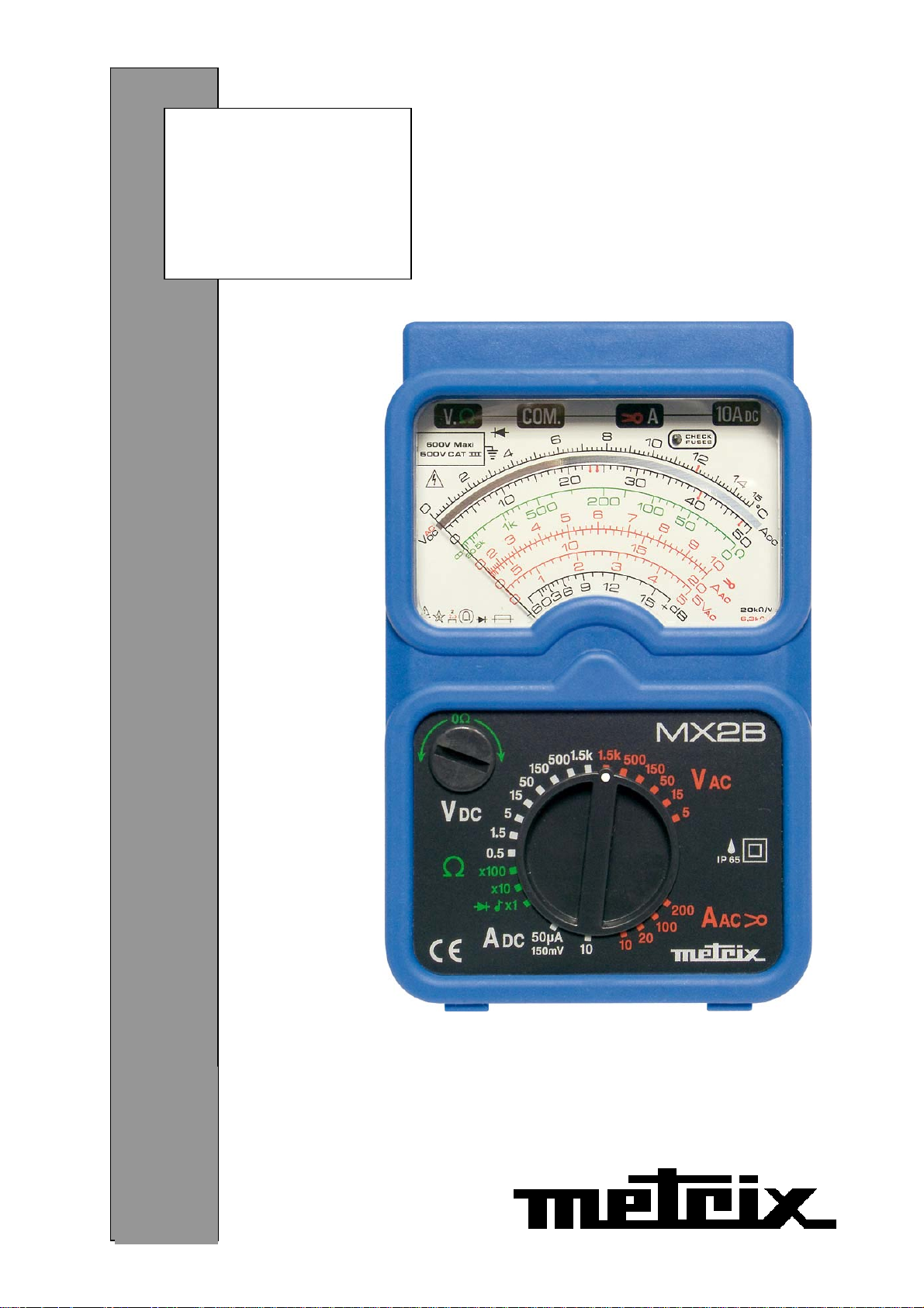
MX2B
FRANÇAIS
ENGLISH
DEUTSCH
ITALIANO
ESPAÑOL
Notice de fonctionnement
User's manual
Bedienungsanleitung
Libretto d'istruzioni
Manual de instrucciones
®
Page 2
Signification du symbole
ATTENTION ! Consulter la notice de fonctionnement avant d'utiliser
l'appareil. Dans la présente notice de fonctionnement, les
instructions précédées de ce symbole, si elles ne sont pas bien
respectées ou réalisées, peuvent occasionner un accident corporel
ou endommager l'appareil et les installations.
Signification du symbole
Cet appareil est protégé par une isolation double ou une isolation
renforcée. Il ne nécessite pas de raccordement à la borne de terre
de protection pour assurer la sécurité électrique.
Vous venez d'acquérir un multimètre MX2B et nous vous remercions de votre
confiance.
Pour obtenir le meilleur service de votre appareil :
- Lisez attentivement cette notice de fonctionnement,
- Respectez les précautions d'emploi.
PRÉCAUTIONS D'EMPLOI
• Ne jamais utiliser sur des réseaux de tension supérieure à 600V par rapport à la
terre. Ce multimètre, de catégorie de surtension III, répond aux exigences de
fiabilité et de disponibilité sévères correspondant aux installations fixes
industrielles et domestiques (cf. IEC 664-1).
• Ne pas utiliser pour des tensions alternatives et continues > 600V.
• Utilisation en intérieur dans des environnements de degré de pollution au plus
égal à 2 (cf. IEC 664-1), de température de -10°C à +50°C et d'humidité relative
inférieur à 90%.
• Respecter la valeur et le type de fusibles sous risque de détérioration de l'appareil
et d'annulation de la garantie.
• Fusible 1,6A HPC (6,3 x 32 mm) 600V - 50kA
• Fusible 10A HPC (6,3 x 32 mm) 600V - 50kA
• Utiliser des accessoires conformes aux normes de sécurité (EN 61010-031) de
tension minimale 600V et de catégorie de surtension III.
• Avant toute mesure, s'assurer du positionnement correct des cordons sur le
multimètre et du commutateur. Lorsque l'ordre de grandeur d'une mesure n'est
pas connu, placer le commutateur sur le calibre le plus élevé, puis baisser
progressivement, si nécessaire, jusqu'au calibre approprié : la lecture doit
s'effectuer, de préférence, dans les 2/3 supérieurs de l'échelle.
• Ne jamais mesurer de résistances sur un circuit sous tension.
• Lors de mesures d'intensité (sans pince ampèremétrique), interrompre
l'alimentation du circuit avant de brancher ou de débrancher le multimètre ou de
changer de calibre.
• Pour ouvrir le 1/2 boîtier inférieur du MX2B, il faut obligatoirement déconnecter les
cordons.
• Ne jamais raccorder au circuit à mesurer, si le boîtier n'est pas correctement
refermé.
1
Page 3
SOMMAIRE
1 - Description .................................................................................................... 2
2 - Condition de référence .................................................................................. 3
3 - Spécifications ................................................................................................ 3
4 - Caractéristiques générales............................................................................ 6
5 - Etat de livraison............................................................................................. 7
Accessoires et rechanges (Pour commander) .............................................. 7
6 - Garantie......................................................................................................... 8
7 - Maintenance.................................................................................................. 8
8 - Annexes ........................................................................................................ 9
1- DESCRIPTION
(Voir Annexe, p. 46)
Le multimètre MX2B est destiné aux besoins quotidiens des professionnels de
l'électricité. Il dispose des fonctions suivantes :
- Voltmètre : mesure des tensions (V et )
- Ampèremètre : mesure des intensités (A et )
- Ohmmètre : mesure des résistances (Ω) avec tarage manuel
- Test sonore de continuité
1 Bornes de sécurité Ø 4 mm
• COM commun, borne recevant le cordon noir
• V Ω pour les tensions et résistances
• A pour les calibres µA
• 10A pour les calibres 10A (DC/AC)
et AAC par pince
DC
2 Cadran 7 échelles
• 2 noires avec miroir anti-parallaxe, pour V
• 1 verte pour les mesures en Ω (c)
• 2 rouges pour les mesures en A
• 1 rouge pour les 5 V
• 1 noire pour les mesures en dB (g)
AC
(f)
(d) et (e)
AC
, VDC et ADC (a) et (b)
AC
3 Voyant de contrôle des fusibles
1,6A et 10A en mesure d'intensité ou de tension, changer le ou les fusibles, si le
voyant est allumé (pour V ≥ 110V).
Nota : le fusible 10A HS provoque l'allumage du voyant sur tous les calibres
(pour V ≥ 110V).
Le fusible 1,6A HS ne provoque l'allumage que sur les calibres µA et mA. Les
autres calibres fonctionnent normalement.
4 Bouton de tarage du zéro en ohmmètre
(correction de l'état d'usure de la pile)
5 Commutateur de sélection des fonctions
2
Page 4

2 - CONDITIONS DE RÉFÉRENCE
Température : 23°C ± 2K
Humidité : 45% RH ± 5%
Position : horizontale ± 2°
Avant toute mesure, s'assurer que l'aiguille est à zéro.
Réglage du zéro : ouvrir l'appareil. Le réglage du zéro mécanique se fait en tournant le
capot transparent à l'arrière du galvanomètre.
S'assurer du positionnement correct du commutateur.
Lorsque l'ordre de grandeur d'une mesure n'est pas connu, placer le commutateur sur
le calibre le plus élevé, puis baisser progressivement, si nécessaire, jusqu'au calibre
approprié : la lecture doit s'effectuer, de préférence, dans les 2/3 supérieurs de
l'échelle.
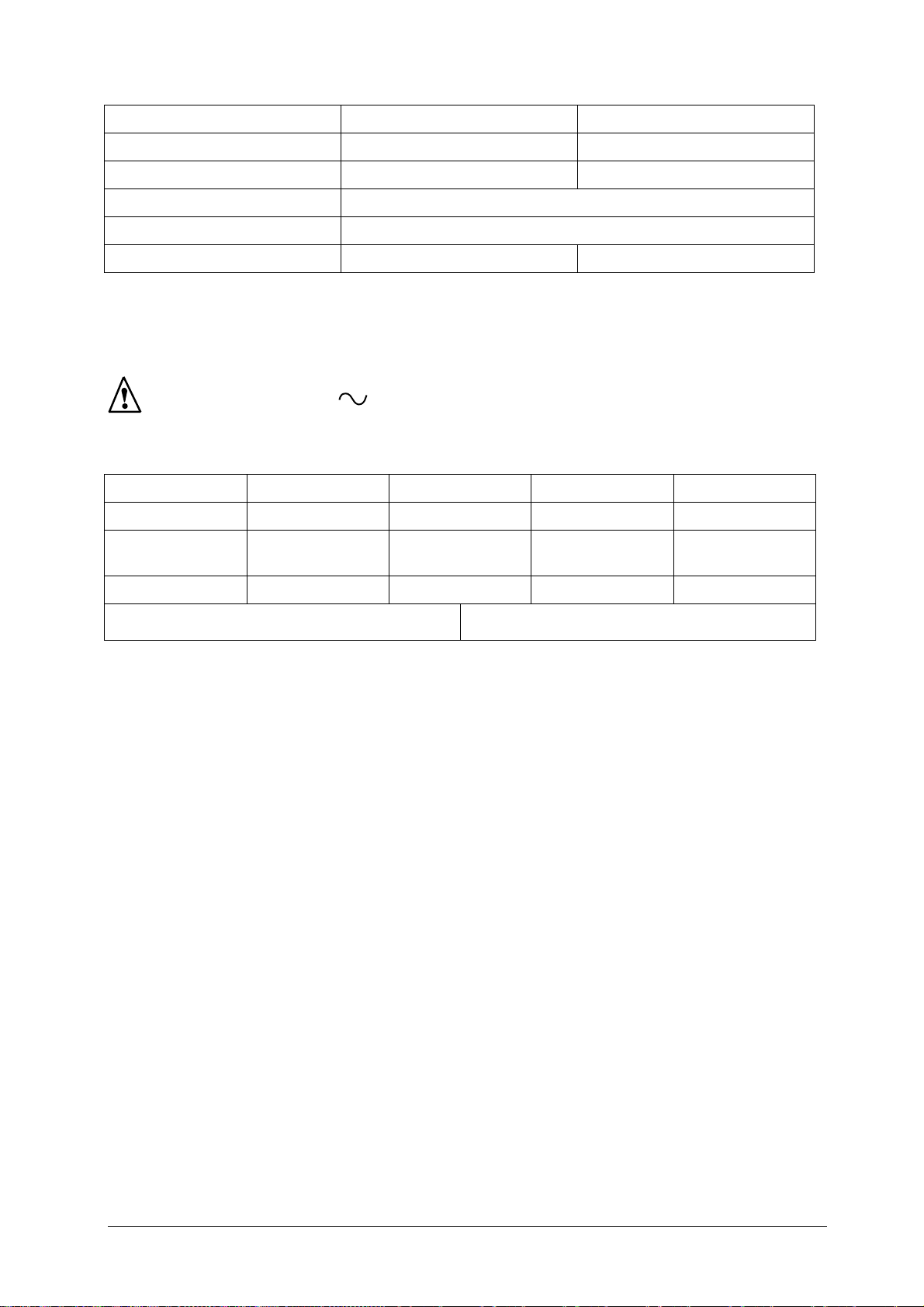
3 - SPÉCIFICATIONS
3-1 TENSIONS CONTINUES
• Raccorder les cordons au multimètre (attention à la position du commutateur, voir
ci-dessous) et se brancher en parallèle sur le circuit à contrôler.
• Lorsque l'ordre de grandeur n'est pas connu, placer le commutateur sur le calibre
le plus élevé, puis baisser progressivement jusqu'au calibre approprié.
• Pour obtenir la tension en V, multiplier la valeur lue sur l'échelle appropriée par le
coefficient de lecture indiqué dans le tableau.
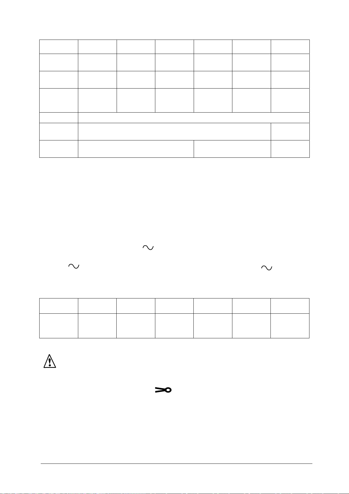
V DC
Echelle
(repère)
Coefficient
de lecture
Résistance
interne (2)
Précision
(3)
Surcharge
admissible
(1) Entrées entre bornes "COM" et "A", les autres calibres entre bornes "COM" et "V Ω"
(2) R spécifique : 20kΩ/V
(3) en % de la fin d'échelle
(4) pendant 1 minute
(5) pendant 20 secondes
150mV
(1)
15 (a) 50 (b) 15 (a) 50 (b) 15 (a) 50 (b) 15 (a) 50 (b) 15 (a)
x 10 x 0.01 x 0.1 x 0.1 x 1 x 1 x 10 x 10 x 100
3kΩ 10kΩ 30kΩ 100kΩ 300kΩ 1MΩ 3MΩ 10MΩ 30MΩ
440V
(fus.)
0.5V 1.5V 5V 15V 50V 150V 500V 1500V
2%
320V (4)
440V (5)
500V 1000V 1500V
3
Page 5
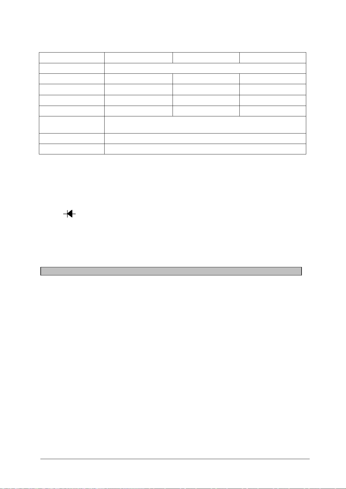
3-2 TENSIONS ALTERNATIVES
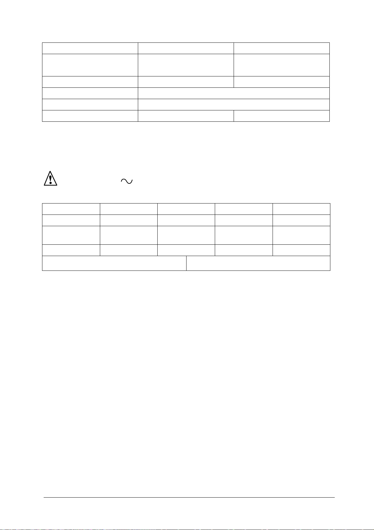
V AC
Échelle
(repère)
Coefficient
de lecture
Résistance
interne (1)
Précision
(2)
Bande
passante
Surcharge
admissible
(1) R spécifique : 2kΩ/V
(2) en % de la fin d'échelle
(3) pendant 1 minute
(4) pendant 20 secondes
5V 15V 50V 150V 500V 1500V
5 V
(f) 15 (a) 50 (b) 15 (a) 50 (b) 15 (a)
AC
x 1 x 1 x 1 x 10 x 10 x 100
10kΩ 30kΩ 100kΩ 300kΩ 1MΩ 3MΩ
La présence d'une composante continue rend la mesure erronée.
3-2-1 DÉCIBELS
• Rappel : la mesure d'une tension alternative peut être exprimée en
décibels (symbole dB). Le décibel est le rapport de deux grandeurs ou
niveaux. Le niveau N, en dB d'une tension U a pour expression
mathématique :
320V (3)
440V (4)
2.5%
16Hz à 1kHz
16Hz à
500Hz
500V 1500V
N (dB) = 20log
(U/U0)
10
U0 est la tension de référence de 0,775V pour une puissance P0 de 1mW
sur une charge de 600Ω.
• Utilisation : Le niveau zéro de l'échelle rouge en dB correspond à
U0 = 0,775V pour le calibre 5V . La lecture est directe en dB pour le
calibre 5V (de -6 à +22dB). Pour les autres calibres, il est possible
de lire en dB (valeur approchée) en ajoutant respectivement :
Calibre 5 VAC 15 VAC 50 VAC 150 VAC 500 VAC 1500 VAC
Lecture G
en dB
Lecture
directe
A = G
A =
G + 10dB
A =
G + 20dB
A =
G + 30dB
A =
G + 40dB
A =
G + 50dB
3-3 INTENSITÉS CONTINUES ET ALTERNATIVES
Toujours interrompre le circuit à contrôler avant de connecter le multimètre sur
le circuit. Si le voyant "Fus" s'allume, changer le(s) fusible(s) défectueux
(Rappel : tension minimum d'allumage = 110V)
Raccorder les cordons au multimètre et se brancher en série dans le circuit
avec : le cordon rouge dans la borne " A" : 50µADC et pince en A
AC
le cordon rouge dans la borne "10ADC" pour le calibre 10ADC uniquement.
Interrompre l'alimentation du circuit avant de raccorder le multimètre (sauf avec
la pince).
• Pour obtenir l'intensité en µA, mA ou A : multiplier la valeur lue sur l'échelle
appropriée par le coefficient de lecture indiqué dans le tableau.
,
4
Page 6
3-3-1 INTENSITÉS CONTINUES
A DC
Échelle (repère) 50 (b) 15 (a) (2/3 utiles)
Coefficient de lecture x 1 x 1
Chute de tension aux bornes (2) < 0.5V
Précision (3) 2%
Protection Fus. 1.6A HPC 50kA 600V Fus. 10A HPC 50kA 600V
(1) entre entrées "A / Pince" et "COM"
(2) sans les cordons
(3) en % de la fin d'échelle
Ne pas utiliser l'entrée A sur des transformateurs d'intensité non protégés.
50µA (1) 10A
3-3-2 INTENSITÉS ALTERNATIVES
A AC
Échelle (repère) 10AAC (d) 20AAC (e) 10AAC (d) 20AAC (e)
Coefficient de
lecture
10A 20A 100A 200A
x 1 x 1 x 10 x 10
Précision (1) 5% 3,5% 3% 3%
Protection (2) Fus. 1.6A HPC 50kA 600V
(1) en % de la fin d'échelle, de 40Hz à 1kHz
Dérive en température = 10% par 10°C
Aux 3%, il faut ajouter l'erreur due à la pince.
(2) entre entrées "A / Pince" et "COM"
5
Page 7
3-4 MESURE DE RÉSISTANCE Ω
Le réglage du zéro de l'ohmmètre se fait par le bouton de tarage (sur la face avant),
en court-circuitant les entrées.
Ω
Échelle (repère) 20k…0 (c)
Coefficient de lecture x 1 x 10 x 100
Ω x 1 (1) Ω x 10 Ω x 100
Étendue de mesure
Résistance interne
Courant fin d'échelle 8mA 800µA 80µA
Tension en circuit
ouvert
Précision ±10% (2) (4)
Surcharge admissible 400V (3)
(1) Buzzer pour R ≤ 100, pas de buzzer pour R ≥ 250Ω
(2) de la valeur mi-échelle
(3) pendant 5 secondes (protection par Résistances et CTP)
(4) pour une tension pile de 1,45V ± 0.1V
10Ω à 20kΩ 100Ω à 200kΩ 1kΩ à 2MΩ
200Ω 2kΩ 20kΩ
1.5V
3-4-1 TEST SONORE DE CONTINUITÉ - TEST SEMI-CONDUCTEUR
NB : En Ω x 1 : seuil "buzzer" ≤ 250Ω, et contrôle du sens passant ou bloqué d'une
diode ( , anode en "COM" pour le sens passant). Ne pas faire de mesure sous
tension.
En ohmmètre, calibre Ω x 1, si on applique une tension VAC > 5V efficaces, le "buzzer"
émet un son modulé jusqu'à correction de l'erreur.
4 - CARACTÉRISTIQUES GÉNÉRALES
4-1 Dimensions et masse
• 97 x 155 x 43 mm
• 420 g
4-2 Alimentation
• 1 pile 1,5V (type R6 saline ou LR6 alcaline)
• Autonomie :
250 heures environ, en ohmmètre, avec une pile alcaline
4000 mesures de 5 secondes pour R < 50Ω (avec bip sonore)
4-3 Conditions climatiques limites
• Température : utilisation -10°C à +50°C ; stockage -30°C à +70°C
• Humidité relative : utilisation ≤ 80% HR
• Altitude : utilisation < 2000m
6
Page 8

4-4 Conformité aux normes internationales
Sécurité électrique (EN 61010-1)
CEI 1010-1 EN61010 NF-C 42020 VDE 0411
• Double isolation :
• Degré de pollution : 2
• Catégorie d'installation : III selon CEI 664
• Tension assignée : 600V
4-5 Compatibilité électromagnétique
• Emission (EN 61326-1)
• Immunité (EN 61326-1)
Influence max. en présence de fréquences radio conduites : 3 fois la classe de
précision si la longueur du circuit mesuré est > 3 m.
4-6 Protection mécanique
• Degré d'étanchéité (EN 60529/A1)
• Indice de protection : IP65
5 - ÉTAT DE LIVRAISON
5-1 Pour commander MX0002B
Livraison :
- 1 multimètre MX2B
- 1 jeu de 2 cordons à pointes de touche
- 4 fusibles, dont 2 de rechange
- 1 pile 1,5V, mise en place
- 1 notice de fonctionnement
- 1 sangle, montée à l'arrière du boîtier
- 1 pince de courant MN09 : rapport 1000/1
5-2 Rechanges et accessoires
- 1 pile LR6 1.5V P01 2960 33
- 1 fusible HPC 1.6A / 6.3 x 32 / 600V / 50kA AT 0071
- 1 fusible HPC 10A / 6.3 x 32 / 600V / 50kA AT 0070
Différents accessoires de mesure élargissent le champ d'application ou confèrent de
nouvelles fonctions au multimètre.
Documentation sur demande.
- Pince de courant : Rapport 1000/1(MN09) P01 1204 02
- Etui de transport 240 x 230 x 70mm avec sangle P01 2980 33
- Jeu de cordons à pointes de touche P01 2950 84
- Jeu de pinces crocodile P01 1018 48
- Sonde haute tension 30kVDC, rapport 100/1 HT 212
7
Page 9

6 - GARANTIE
Notre garantie s'exerce, sauf stipulation expresse, pendant trois ans pour le multimètre
et un an pour les accessoires après la date de mise à disposition du matériel (extrait
de nos Conditions Générales de Vente, communiquées sur demande).
7 - MAINTENANCE
Pour la maintenance, utiliser seulement les pièces de rechange qui ont
été spécifiées. Le fabricant ne pourra être tenu pour responsable de tout
incident survenu suite à une réparation effectuée en dehors de son
service après-vente ou des réparateurs agréés.
7-1 Remplacement de la pile et des fusibles
Ouverture du multimètre
Pour ouvrir l'appareil, débrancher les cordons de mesure et ôter les quatre vis situées
au dos. Enlever ensuite le 1/2 boîtier inférieur.
7-1-1 Changement de pile
Ouvrir l'appareil. Changer la pile si, sur le calibre Ω x 1, le "buzzer" ne fonctionne pas
quand les entrées VΩ et COM sont en court-circuit. Respecter la polarité de la pile
dans son logement.
7-1-2 Remplacement des fusibles
Ouvrir l'appareil. Pour la sécurité de l'utilisateur, et celle de l'appareil, remplacer les
fusibles, par des fusibles de même type.
Un néon s'allume quand l'un des fusibles 1,6A et/ou 10A est (sont) coupé(s), et qu'une
tension V
> 110V existe entre les bornes :
AC
A et COM = (fusible(s) 1.6 et/ou 10A HS),
10A et COM = (fusible 10A HS).
Egalement, pour le fusible 10A coupé :
• entre les bornes VΩ et COM, sur les calibres V
150V
avec une tension de 110VAC;
AC
• entre les bornes VΩ et COM, sur les calibres V
inférieurs à 50VDC et
DC
inférieurs à 500VDC
DC
et 1500VAC pour une tension VAC > 220V.
7-2 Stockage
Si le multimètre n'est pas mis en service pendant une période dépassant 60 jours,
enlever la pile et la stocker séparément.
Pour une période plus courte, éviter de laisser le multimètre sur une position
ohmmètre, il y a risque d'usure prématurée de la pile si les pointes de touches
viennent en contact.
8
Page 10
7-3 Nettoyage
• Le multimètre doit être déconnecté de toute source électrique.
• Pour nettoyer le boîtier, utiliser un chiffon légèrement imbibé d'eau
savonneuse. Essuyer avec un chiffon humide. Ensuite, sécher rapidement
avec un chiffon sec ou de l'air pulsé.
7-4 Vérification métrologique
Comme tous les appareils de mesure ou d'essais, une vérification
périodique est nécessaire.
Pour les vérifications et étalonnages de vos appareils, adressez-vous à nos laboratoires
de métrologie accrédités par le COFRAC ou aux agences MANUMESURE.
Renseignements et coordonnées sur demande :
Tél. : 02 31 64 51 43 Fax : 02 31 64 51 09
7-5 Réparation sous garantie et hors garantie
Adressez vos appareils à l'une des agences régionales MANUMESURE, agréées
CHAUVIN-ARNOUX.
Renseignements et coordonnées sur demande :
Tél. : 02 31 64 51 43 Fax : 02 31 64 51 09
7-6 Réparation hors de France métropolitaine
Pour toute intervention sous garantie ou hors garantie, retournez l'appareil à votre
distributeur.
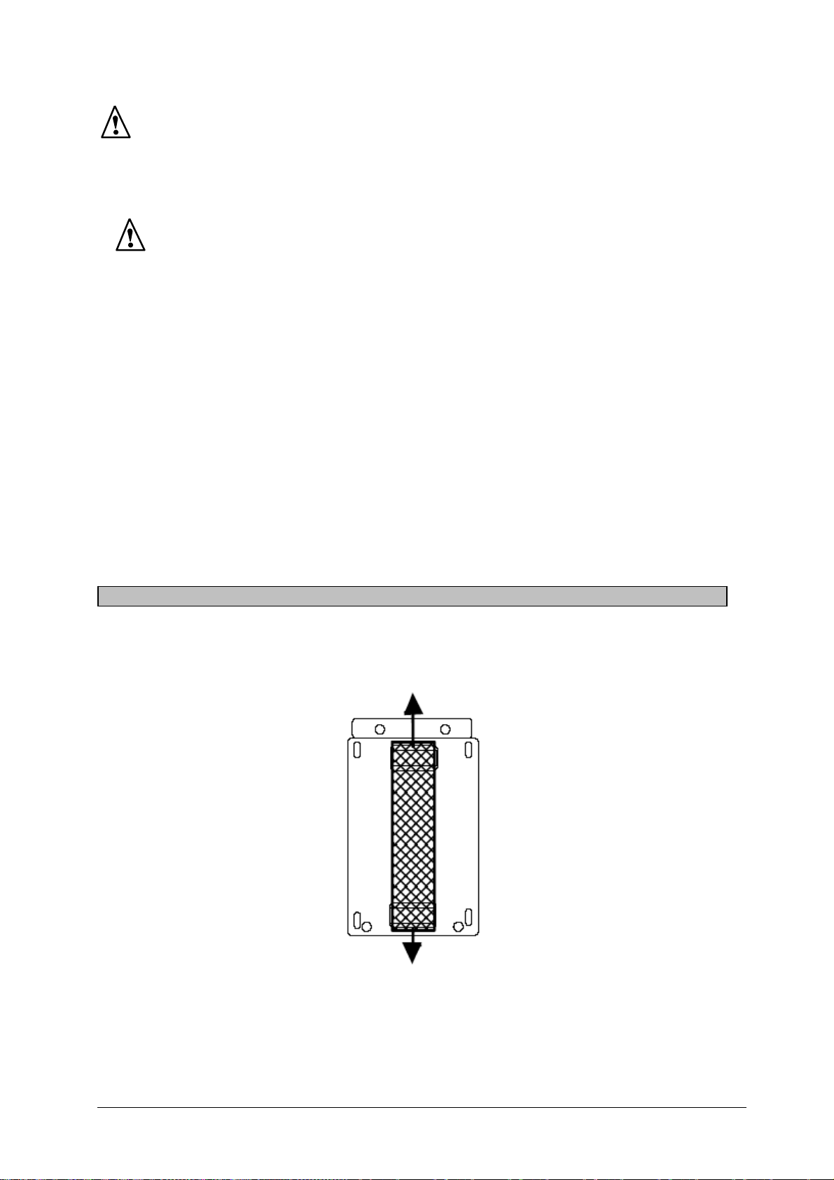
8 - ANNEXE
8-1 Sa ngle
Pour ôter la sangle (montée sur l'arrière du boîtier) : tirer selon les flèches.
•
8-2 Description
Voir p. 46.
9
Page 11
Meaning of symbol
CAUTION! Please consult the operating instructions before using
the device. In these operating instructions, failure to follow or carry
out instructions preceded by this symbol may result in personal
injury or damage to the device and the installations.
Meaning of symbol
This appliance is protected by double insulation or reinforced
insulation. It does not have to be connected to an earth protection
terminal for electrical safety.
Thank you for purchasing this MX2B multimeter.
To obtain the best service from your unit:
• Read these operating instructions carefully,
•
Comply with the precautions for use.
PRECAUTIONS FOR USE
• Never use on a voltage network over 600V with respect to the earth connection.
This voltage surge category III multimeter complies with stringent reliability and
availability requirements, corresponding to fixed industrial and domestic
installations (see IEC 664-1).
• Do not use on alternative and continuous voltages > 600V.
• Indoor use in environments with a maximum pollution level of 2 (cf. IEC 664-1),
temperature of -10°C to +50°C and relative humidity below 90%.
• Respect the value and type of the fuses to avoid damaging the instrument and
cancelling the warranty.
• 1.6A HPC fuse (6.3 x 32mm) 600V - 50kA
• 10A HPC fuse (6.3 x 32mm) 600V - 50kA
• Use accessories corresponding to safety standards (EN 61010 - 031) with 600V
minimum voltage and surge category III.
• Before any measurement, ensure correct positioning of the leads on the
multimeter and of the switch. When the value range of a measurement is not
known, place the switch at the highest calibre, then gradually reduce it until the
appropriate calibre is achieved: the reading should preferably be in the upper 2/3
of the range.
•
Never measure resistances on a live circuit.
• During current intensity measurements (without a clip-on ammeter), stop circuit
power supply before connecting or disconnecting the multimeter or changing
calibre.
• The leads must be disconnected to open the lower half of the MX2B casing.
• Never connect to the circuit to be measured if the casing is not properly closed.
10
Page 12
CONTENTS
1 - Description .................................................................................................. 11
2 - Reference conditions................................................................................... 12
3 - Specifications .............................................................................................. 12
4 - General characteristics................................................................................ 15
5 - Supply ......................................................................................................... 16
Accessories and spare parts (orders) ......................................................... 16
6 - Warranty...................................................................................................... 17
7 - Maintenance................................................................................................ 17
8 - Appendices.................................................................................................. 18
1 - DESCRIPTION
(See Appendix, p. 46).
The MX2B multimeter is for everyday use by electricity professionals. It offers the
following functions:
- Voltmeter: voltage measurement (V and )
- Ammeter: current intensity measurement (A and )
- Ohmmeter: resistance measurement (Ω) with manual calibration.
- Audible continuity test
1 Safety terminals, Ø 4 mm
• COM common, terminal receiving the black lead.
• V Ω for voltage and resistance.
• A for µA
• 10A for 10A calibres (
and AAC calibres using a clamp.
DC
).
DC/AC
2 7-range dial
• 2 black, with anti-parallaxe mirror, for the V
• 1 green for the Ω measurements (c).
• 2 red for the A
• 1 red for the 5 V
• 1 black for the dB measurements (g).
measurements (d) and (e).
AC
(f).
AC
, VDC and ADC (a) and (b).
AC
3 Fuse indicator LED
1.6A and 10A for intensity or voltage measurements, change the fuse(s) if the
LED is on (for V≥ 110V).
Note: with the HS 10A fuse, the LED comes on for all calibres (for V ≥ 110V).
The HS 1.6A fuse only causes it to come on for µA and mA calibres. The other
calibres operate normally.
4 Zero calibration button on the ohmmeter
(correction of battery wear status)
5 Function selection switch
11
Page 13

2 - REFERENCE CONDITIONS
Temperature: 23°C ± 2K
Humidity: 45% RH ± 5%
Position: horizontal ± 2°
Ensure that the pointer is at zero before starting any measurements.
Zero adjustment: open the device. Mechanical zero adjustment is carried out by
turning the transparent cover on the back of the null meter.
Ensure that the switch is correctly positioned.
When an estimated measurement is unknown, place the switch at the highest calibre,
then gradually reduce it until the appropriate calibre is achieved: the reading should
preferably be in the upper 2/3 of the range.
3 - SPECIFICATIONS
3-1 DC VOLTAGE
• Connect the leads to the multimeter (be careful of switch position, see below) and
connect to the circuit to be controlled.
•
When an estimated measurement is unknown, place the switch at the highest
calibre, then gradually reduce it until the appropriate calibre is achieved.
To obtain voltage in V, multiply the appropriate range value by the reading
•
coefficient indicated in the table.
V DC
Range
(indication)
Reading
coefficient
Internal
resistance
(2)
Accuracy
(3)
Admissible
overload
(1) Inputs between "COM" and "A" terminals, the other calibres between "COM" and "V Ω" terminals.
(2) Specific R: 20kΩ/V
(3) in % of end of range
(4) for 1 minute
(5) for 20 seconds
150mV
(1)
15 (a) 50 (b) 15 (a) 50 (b) 15 (a) 50 (b) 15 (a) 50 (b) 15 (a)
x 10 x 0.01 x 0.1 x 0.1 x 1 x 1 x 10 x 10 x 100
3kΩ 10kΩ 30kΩ 100kΩ 300kΩ 1MΩ 3MΩ 10MΩ 30MΩ
440V
(fuse)
0.5V 1.5V 5V 15V 50V 150V 500V 1500V
2%
320V (4)
440V (5)
500V 1000V 1500V
12
Page 14
3-2 AC VOLTAGE
V AC
Range
(indication)
Reading
coefficient
Internal
resistance
(1)
Accuracy (2) 2.5%
Bandwidth
Admissible
overload
(1) Specific R: 2kΩ/V
(2) in % of end of range
(3) for 1 minute
(4) for 20 seconds
5V 15V 50V 150V 500V 1500V
5 VAC (f) 15 (a) 50 (b) 15 (a) 50 (b) 15 (a)
x 1 x 1 x 1 x 10 x 10 x 100
10kΩ 30kΩ 100kΩ 300kΩ 1MΩ 3MΩ
16Hz to
500Hz
320V (3)
440V (4)
16Hz to 1kHz
500V 1500V
The presence of a DC component falsifies the measurement.
3-2-1 DECIBELS
• Reminder: measurement of AC voltage may be expressed in decibels (dB). A
decibel is the ratio between two measurements or levels. Level N in dB for U
voltage is mathematically expressed as:
N (dB) = 20log
(U/U
10
)
0
U0 is reference voltage 0.775V for P0 power of 1mW for a load of 600Ω.
•
Use: The zero level on the red range in dB corresponds to U
= 0.775V for calibre
0
of 5V . Readings are given in dB directly for the calibre 5V (from -6 to
+22dB). For the other calibres, it is possible to read in dB (approximate value) by
adding respectively:
Calibre 5 VAC 15 VAC 50VAC 150 VAC 500 VAC 1500 VAC
Reading G
in dB
Direct
reading
A = G
A =
G + 10dB
A =
G + 20dB
A =
G + 30dB
A =
G + 40dB
A =
G + 50dB
3-3 DC AND AC INTENSITIES
Always cut the power supply on the circuit to be controlled before connecting
the multimeter to the circuit. If the "Fus" LED is on, change the faulty fuse(s).
(Reminder: minimum voltage for LED = 110V).
Connect the leads to the multimeter and connect in series in the circuit with:
- The red lead in terminal " A": 50µA
and clamp in AAC.
DC
- The red lead in the "10ADC" terminal for 10ADC calibre only.
Cut circuit power supply before connecting the multimeter (except with the
clamp).
To obtain intensity in µA, mA or A: multiply the value on the appropriate scale by the
reading coefficient indicated in the table.
13
Page 15
3-3-1 DC INTENSITIES
A DC
Scale (indication) 50 (b) 15 (a)
Reading coefficient x 1 x 1
Voltage drop on terminals (2) < 0.5V
Accuracy (3) 2%
Protection 1.6A HPC fuse 50kA 600V 10A HPC fuse 50kA 600V
(1) between "A / clamp" and "COM" inputs
(2) without leads
(3) in % of end of scale
Do not use input A on unprotected intensity transformers.
50µA (1) 10A
(2/3 useful)
3-3-2 AC INTENSITIES
A AC
Scale (indication) 10AAC (d) 20AAC (e) 10AAC (d) 20AAC (e)
10A 20A 100A 200A
Reading
coefficient
Accuracy (1) 5% 3.5% 3% 3%
Protection (2) 1.6A HPC fuse 50kA 600V
(1) in % of end of scale from 40Hz to 1kHz
Drift impact in temp. = 10% by 10°C
Add the error from the clamp to the 3%
(2) between "A / Clamp" and "COM" inputs
x 1 x 1 x 10 x 10
14
Page 16

3-4 Ω RESISTANCE MEASUREMENT
Zero adjustment on the ohmmeter is carried out using the calibration button (front) by
short-circuiting the inputs.
Ω
Scale (indication) 20k…0 (c)
Reading coefficient x 1 x 10 x 100
Ω x 1 (1) Ω x 10 Ω x 100
Measuring scale
Internal resistance
End of scale current 8mA 800µA 80µA
Open circuit voltage 1.5V
Accuracy ±10% (2) (4)
Admissible overload 400V (3)
(1) Buzzer for R ≤ 100, no buzzer for R ≥ 250Ω
(2) of the mid-scale value
(3) for 5 seconds (protection by Resistances and CTP)
(4) for battery voltage of 1.45V ± 0.1V
10Ω to 20kΩ 100Ω to 200kΩ 1kΩ to 2MΩ
200Ω 2kΩ 20kΩ
3-4-1 AUDIBLE CONTINUITY TEST - SEMI-CONDUCTOR TEST
NB : In Ω x 1: "buzzer" threshold ≤ 250Ω, control of diode on or blocked ( , anode
in "COM" for on). Do not carry out live measurements.
On the ohmmeter, calibre Ω x 1, if voltage of VAC > 5V (rms) is applied, the "buzzer"
issues a modulated sound until the error has been corrected.
4 - GENERAL CHARACTERISTICS
4-1 Dimensions and weight
• 97 x 155 x 43 mm
•
420 g
4-2 Power supply
• 1.5V battery (R6 saline or LR6 alkaline)
•
Battery life:
about 250 hours for the ohmmeter with an alkaline battery
4000 5-second measurements for R < 50Ω (with beep)
4-3 Maximum climatic conditions
• Temperature: use -10°C to +50°C ; storage -30°C to +70°C
Relative humidity: use ≤ 80% HR
•
•
Altitude: use < 2000m
15
Page 17

4-4 Compliance with international standards
Electrical safety (EN 61010-1)
CEI 1010-1 EN61010 NF-C 42020 VDE 0411
• Double insulation:
Pollution level: 2
•
Installation category: III according to CEI 664
•
Allocated voltage: 600V
•
4-5 Electromagnetic compatibility
• Emission (EN 61326-1)
•
Immunity (EN 61326-1)
Maximum influence in the presence of conducted radio frequencies: 3 times the
accuracy class if the length of the measured circuit is > 3 m.
4-6 Mechanical protection
• Watertightness (EN 60529/A1)
•
Protection index: IP65
5 - SUPPLY
5-1 To order MX0002B
Delivery:
- 1 MX2B multimeter
- 1 set of 2 leads with tips
- 4 fuses, 2 spares
- 1 fitted 1.5V battery
- 1 instructions leaflet
- 1 strap on the back of the casing
- 1 MN09 current clamp: 1000/1 ratio
5-2 Spare parts and accessories
- 1 LR6 1.5V battery P01 2960 33
- 1 HPC fuse 1.6A / 6.3 x 32 / 600V / 50kA AT 0071
- 1 HPC fuse 10A / 6.3 x 32 / 600V / 50kA AT 0070
Different measurement accessories widen the scope of application or provide the
altimeter with new functions.
Documentation on request.
- Current clamp: ratio 1000/1 (MN09) P01 1204 02
- Carry case 240 x 230 x 70mm with strap P01 2980 33
- Set of leads with tips P01 2950 84
- Set of crocodile clamps P01 1018 48
- 30kV
high voltage probe, ratio 100/1 HT 212
DC
16
Page 18

6 - WARRANTY
Our warranty lasts three years for the multimeter and one year for the accessories
after the delivery date except for express stipulations (extract from our General Sales
Terms provided on request).
7 - MAINTENANCE
Only use the specified spare parts for maintenance. The manufacturer
shall not be held liable for any incident occurring following repairs carried
out by a party other than its after-sales service or approved repairers.
7-1 Battery and fuse change
Opening the multimeter:
Open the device by removing the measurement leads and taking out the four screws
on the back. Remove the lower part of the casing.
7-1-1 Changing the battery
Open the device. Change the battery if the buzzer does not function when the VΩ and
COM inputs are in short-circuit on the Ω x 1 calibre. Ensure that the battery is the right
way up.
7-1-2 Changing the fuses
Open the device. Use the same type of fuses to ensure the safety of users and of the
device.
A LED comes on when one of the 1.6A and/or 10A fuses has blown and there is
voltage of V
> 110V between the terminals.
AC
A and COM = (HS 1.6 and/or 10A fuse(s)),
10A and COM = (HS 10A fuse).
Also, for a blown 10A fuse:
between the VΩ and COM terminals, on the VDC calibres under 50VDC and 150V
AC
with
voltage of 110VAC;
between the VΩ and COM terminals, on the VDC calibres under 500VDC and 1500V
with voltage of V
> 220V.
AC
AC
7-2 Storage
If the multimeter is not used for a period of over 60 days, remove the battery and store
it separately.
For a shorter period, avoid leaving the multimeter in ohmmeter position. There is a risk
of premature battery wear if the tips come into contact with it.
17
Page 19

7-3 Cleaning
• The multimeter must be disconnected from all electricity sources.
To clean the casing, use a cloth dampened with soapy water. Wipe over with a
•
damp cloth. Dry quickly with a dry cloth or forced air.
7-4 Metrology checks
Regular checks must be carried out as for all measurement or test
devices.
For checks and calibration, contact our COFRAC-approved metrology laboratories or
branches of MANUMESURE.
Information and contact details on request:
Tel.: 02 31 64 51 43 Fax: 02 31 64 51 09
7-5 Repairs under warranty and outside of the warranty
Send your devices to a regional MANUMESURE branch approved by Chauvin-Arnoux.
Information and contact details on request:
Tel.: 02 31 64 51 43 Fax: 02 31 64 51 09
7-6 Repairs outside of Metropolitan France
For all repairs under the warranty or outside of the warranty, return the device to your
retailer.
8 - APPENDIX
8-1 Strap
Remove the strap (on the back of the casing) by pulling in the direction of the arrows.
8-2 Description
See p. 46.
18
Page 20

Bedeutung des Zeichens
ACHTUNG! Lesen Sie die Bedienungsanleitung, bevor Sie das
Gerät benutzen. Werden die Anweisungen in dieser
Bedienungsanleitung, denen dieses Symbol vorangestellt ist, nicht
beachtet oder eingehalten, kann es zu Verletzungen von Menschen
oder Beschädigungen des Geräts oder der Installationen kommen.
Bedeutung des Zeichens
Das Gerät ist schutzisoliert bzw. durch eine verstärkte Isolierung
geschützt. Der Anschluss an einen Erdleiter ist für die
Gewährleistung der elektrischen Sicherheit nicht erforderlich.
Wir danken Ihnen für das Vertrauen, dass Sie uns mit dem Kauf dieses Multimeters
MX2B entgegengebracht haben.
Damit die optimale Nutzung des Geräts gewährleistet ist:
- Lesen diese Bedienungsanleitung sorgfältig durch.
- Beachten Sie die Sicherheitshinweise.
SICHERHEITSHINWEISE
• Setzen Sie das Gerät niemals an Netzen mit Spannungen von mehr als 600 V
gegenüber Erde ein. Dieses Multimeter der Überspannungskategorie III
entspricht den strengen Zuverlässigkeits- und Verfügbarkeitsanforderungen für
feste Industrie- und Hausinstallationen (siehe IEC 664-1).
• Nicht auf DC- oder AC-Spannungen > 600V verwenden.
• Dieses Gerät wurde für die Verwendung in Innenräumen in einer Umgebung mit
einem Verschmutzungsgrad von maximal gleich 2 (siehe IEC 664-1), einer
Temperatur zwischen -10°C und +50°C und einer relativen Feuchte von unter 90 %
entwickelt.
• Halten Sie Wert und Typ der Sicherungen genau ein, da ansonsten das Gerät
beschädigt werden kann und die Garantie erlischt.
• Sicherung 1,6 A HPC (6,3 x 32 mm) 600 V - 50 kA
• Sicherung 10 A HPC (6,3 x 32 mm) 600 V - 50 kA
• Verwenden Sie nur Zubehör, das den Sicherheitsnormen (EN 61010-031) für
minimale Spannung von 600 V und der Überspannungskategorie III entspricht.
• Überprüfen Sie vor der Durchführung einer Messung die richtige Anordnung der
Messleitungen am Multimeter und die richtige Position des Wahlschalters. Wenn die
Größenordnung einer Messung nicht bekannt ist, stellen Sie den Wahlschalter auf
den größten Messbereich und schalten ihn gegebenenfalls schrittweise bis zum
geeigneten Messbereich herunter: Der Anzeigewert sollte vorzugsweise in den
oberen 2/3 der Skala liegen.
•
Führen Sie niemals Widerstandsmessungen an einem unter Spannung stehenden
Kreis durch.
• Unterbrechen Sie bei der Messung von Stromstärken (ohne Zangenstromwandler)
die Stromversorgung des Kreises, bevor Sie das Multimeter anschließen oder
abklemmen.
• Damit die untere Gehäusehälfte des MX2B geöffnet werden kann, müssen
unbedingt die Messleitungen abgezogen werden.
Schließen Sie das Multimeter niemals an einen Messkreis an, wenn sein Gehäuse
nicht richtig geschlossen ist.
19
Page 21

INHALT
1 - Beschreibung ............................................................................................. 20
2 - Bezugsbedingungen.................................................................................... 21
3 - Spezifikationen ............................................................................................ 21
4 - Allgemeine Daten ........................................................................................ 24
5 - Lieferzustand............................................................................................... 25
Bestellangaben für Zubehör und Ersatzteile ............................................... 25
6 - Garantie....................................................................................................... 26
7 - Wartung....................................................................................................... 26
8 - Anlagen ....................................................................................................... 27
1 - BESCHREIBUNG
(Siehe Anlage, S. 46).
Das Multimeter MX2B ist für den täglichen Bedarf von Fachleuten aus dem
Elektrobereich bestimmt. Es verfügt über die folgenden Funktionen:
- Voltmeter Messung von Spannungen (V und )
- Amperemeter Messung von Strömen (A und )
- Ohmmeter Messung von Widerständen (Ω) mit manuellem Abgleich
- Akustische Durchgangsprüfung
1 Sicherheitsbuchsen Ø 4 mm
COM Buchse für die schwarze Messleitung (alle Messungen)
•
• V Ω für Spannungs- und Widerstandsmessungen
• A für Strommessungen per Zangenstromwandler in den
Bereichen µADC und AAC
• 10A für Strommessungen im Bereich 10 A (DC/AC)
2 Anzeige mit 7 Skalen
• 2 schwarze Skalen mit Anti-Parallaxen-Spiegel für V
und (b)
1 grüne Skala für Messungen in Ω (c)
•
•
2 rote Skalen für Messungen in AAC (d) und (e)
•
1 rote Skala für 5 VAC (f)
•
1 schwarze Skala für Messungen in dB (g)
, VDC und ADC (a)
AC
3 Kontrollleuchte und Sicherungen
1,6 A und 10 A für Strom- und Spannungsmessung. Die Sicherung(en) sind
auszutauschen, wenn die Kontrollleuchte aufleuchtet (bei V ≥ 110 V).
Anmerkung:
Kontrollleuchte in allen Messbereichen (bei V ≥ 110 V).
Die Sicherung 1,6 A HS führt nur in den Messbereichen µA und mA zu einem
Aufleuchten. Die anderen Messbereiche funktionieren normal.
Die Sicherung 10 A HS führt zu einem Aufleuchten der
4 Einstellknopf für den Nullabgleich des Ohmmeters
(Korrektur des Ladezustands der Batterie)
5 Wahlschalter zur Funktionsauswahl
20
Page 22

2 - BEZUGSBEDINGUNGEN
Temperatur: 23°C ± 2 K
Feuchte: 45 % r. F. ± 5 %
Position: horizontal ± 2°
Vergewissern Sie sich vor jeder Messung, dass sich die Nadel auf dem Nullpunkt
befindet.
Einstellung des Nullpunkts: Öffnen Sie das Gerät. Die Einstellung des mechanischen
Nullpunkts erfolgt durch Drehen der transparenten Abdeckung auf der Rückseite des
Galvanometers.
Überprüfen Sie die richtige Position des Wahlschalters.
Wenn die Größenordnung einer Messung nicht bekannt ist, stellen Sie den
Wahlschalter auf den größten Messbereich und schalten ihn gegebenenfalls
schrittweise bis zum geeigneten Messbereich herunter: Der Anzeigewert sollte
vorzugsweise in den oberen 2/3 der Skala liegen.
3 - SPEZIFIKATIONEN
3-1 GLEICHSPANNUNGEN
• Schließen Sie die Messleitungen an das Multimeter an (achten Sie auf die Position
des Wahlschalters, siehe oben) und messen Sie parallel zum zu überprüfenden
Kreis.
•
Wenn die Größenordnung nicht bekannt ist, stellen Sie den Wahlschalter auf den
größten Messbereich und schalten ihn schrittweise bis zum geeigneten
Messbereich herunter.
•
Um die Spannung in V zu erhalten, müssen Sie den auf der entsprechenden Skala
abgelesenen Wert mit dem in der Tabelle angegebenen Koeffizienten
multiplizieren.
V DC
Skala
(Kenn-
zeichen)
Koeffizient x 10 x 0.01 x 0.1 x 0.1 x 1 x 1 x 10 x 10 x 100
Innen-
widerstand
(2)
Genauigkeit
(3)
150 mV
(1)
15 (a) 50 (b) 15 (a) 50 (b) 15 (a) 50 (b) 15 (a) 50 (b) 15 (a)
3kΩ 10kΩ 30kΩ 100kΩ 300kΩ 1MΩ 3MΩ 10MΩ 30MΩ
0.5 V 1.5 V 5 V 15 V 50 V 150 V 500 V 1500 V
2 %
Zulässige
Überlast
(1) Eingang zwischen den Buchsen "COM" und "A", bei den anderen Messbereichen zwischen den
Buchsen "COM" und "V Ω"
(2) R spezifisch: 20 kΩ/V
(3) in % des Endskalas
(4) für 1 Minute
(5) für 20 Sekunden
440 V
(Sich.)
320 V (4)
440 V (5)
500 V 1000 V 1500 V
21
Page 23

3-2 WECHSELSPANNUNGEN
V AC
Skala 5 VAC (f) 15 (a) 50 (b) 15 (a) 50 (b) 15 (a)
Koeffizient x 1 x 1 x 1 x 10 x 10 x 100
Innenwiderst. (1)
Genauigkeit (2) 2,5 %
Bandbreite
Zulässige
Überlast
(1) R spezifisch: 2 kΩ/V
(2) in % des Endskalas
(3) für 1 Minute
(4) für 20 Sekunden
5 V 15 V 50 V 150 V 500 V 1500 V
10 kΩ 30 kΩ 100 kΩ 300 kΩ 1 MΩ 3 MΩ
16 Hz bis
500 Hz
320 V (3)
440 V (4)
16 Hz bis 1 kHz
500 V 1500 V
Das Vorhandensein einer Gleichkomponente führt zu einer fehlerhaften Messung.
3-2-1 DEZIBEL
• Erinnerung: Die Messung einer Wechselspannung kann in Dezibel
(Symbol dB) ausgedrückt werden. Dezibel ist das Verhältnis von zwei
Größen oder Pegeln. Der Pegel N in dB einer Spannung U hat den
mathematischen Ausdruck:
N (dB) = 20log
(U/U0)
10
U0 ist die Referenzspannung von 0,775 V bei einer Leistung P0 von 1 mW
an einer Last von 600 Ω.
Betrieb: Der Nullpegel der roten Skala in dB entspricht
•
U0 = 0,775 V für den Messbereich 5 V . Die Ablesung erfolgt direkt in
dB für den Messbereich 5 V (von -6 bis +22 dB). Bei den anderen
Messbereichen kann in dB (angenäherter Wert) abgelesen werden,
indem die entsprechenden Werte der folgenden Tabelle hinzugefügt
werden:
Messber. 5 VAC 15 VAC 50 VAC 150 VAC 500 VAC 1500 VAC
Ablesung
G in dB
Direkt-
ablesung
A =
G + 10 dB
A =
G + 20 dB
A =
G + 30 dB
A =
G + 40 dB
A =
G + 50 dB
A = G
3-3 GLEICH- UND WECHSELSTRÖME
Unterbrechen Sie vor dem Anschluss des Multimeters immer den zu
messenden Stromkreis. Wenn die Kontrollleuchte "Fus" aufleuchtet, wechseln
Sie bitte die defekte(n) Sicherung(en) aus (Erinnerung: Mindestspannung für
das Aufleuchten = 110 V)
Schließen Sie die Messleitungen an das Multimeter an und messen Sie in
Reihe mit dem zu überprüfenden Kreis.
- Rote Messleitung an Klemme " A": 50µA
und Zange an AAC.
DC
- Die rote Messleitung wird nur für den Messbereich 10ADC an die Klemme
"10ADC" angeschlossen.
Unterbrechen Sie vor dem Anschluss des Multimeters die Stromversorgung des
Kreises (außer bei Messung mit Zangenstromwandler).
So erhalten Sie die Stromstärke in µA, mA oder A: Multiplizieren Sie den auf der
entsprechenden Skala abgelesenen Wert mit dem in der Tabelle angegebenen
Koeffizienten.
22
Page 24

3-3-1 GLEICHSTRÖME
A DC
Skala (Kennzeichen) 50 (b) 15 (a)
Koeffizient x 1 x 1
Spannungsabfall an den
Anschlüssen (2)
Genauigkeit (3) 2 %
Schutz Sich. 1,6 A HPC 50 kA 600 V Sich. 10 A HPC 50 kA 600 V
(1) zwischen den Eingängen "A / Zange" und "COM"
(2) ohne Messleitungen
(3) in % des Endausschlags
Verwenden Sie den Eingang A nicht bei ungeschützten Stromtransformatoren.
50 µA (1) 10 A
(2/3 Nutzbereich)
< 0,5 V
3-3-2 WECHSELSTRÖME
A AC
Skala
(Kennzeichen)
10 A 20 A 100 A 200 A
10 AAC (d) 20 AAC (e) 10 AAC (d) 20 AAC (e)
Koeffizient x 1 x 1 x 10 x 10
Genauigkeit (1) 5 % 3,5 % 3 % 3 %
Schutz (2) Sich. 1,6 A HPC 50 kA 600 V
(1) in % des Endskalas, bei 40 Hz bis 1 kHz
Temperaturabweichung = 10 % pro 10°C
Es sind 3 % für den Fehler aufgrund des Zangenstromwandlers hinzuzufügen.
(2) zwischen den Eingängen "A / Zange" und "COM"
23
Page 25

3-4 WIDERSTANDSMESSUNG Ω
Die Nullpunkteinstellung des Ohmmeters erfolgt bei kurzgeschlossenen Eingängen
über den Einstellknopf (auf der Vorderseite).
Ω
Skala (Kennzeichen) 20 k…0 (c)
Koeffizient x 1 x 10 x 100
Ω x 1 (1) Ω x 10 Ω x 100
Messspanne
Innenwiderstand
Strom bei Endskala 8 mA 800 µA 80 µA
Spannung bei offenem
Kreis
Genauigkeit ±10 % (2) (4)
Zulässige Überlast 400 V (3)
(1) Summer bei R ≤ 100, kein Summer bei R ≥ 250 Ω
(2) des Wertes bei halber Skala
(3) für 5 Sekunden (Schutz über Widerstand und PTC)
(4) bei einer Batteriespannung von 1,45 V ± 0,1 V
10Ω bis 20 kΩ 100Ω bis 200 kΩ 1 kΩ bis 2 MΩ
200 Ω 2 kΩ 20 kΩ
1,5 V
3-4-1 AKUSTISCHE DURCHGANGSPRÜFUNG - HALBLEITERPRÜFUNG
Hinweis: Bei Ω x 1: Schwelle des "Summers" ≤ 250 Ω und Überprüfung der
Durchgangs- und Sperrrichtung einer Diode ( , Anode für Durchgangsrichtung an
"COM"). Führen Sie keine Messungen unter Spannung durch.
Wird beim Ohmmeter im Messbereich Ω x 1 eine Spannung von VAC > 5 Veffektiv
angelegt, gibt der "Summer" bis zur Behebung des Fehlers ein moduliertes Tonsignal ab.
4 - ALLGEMEINE DATEN
4-1 Abmessungen und Gewicht
• 97 x 155 x 43 mm
• 420 g
4-2 Stromversorgung
• Eine Batterie 1,5 V (Typ R6 Zink-Chlorid oder LR6 Alkali)
•
Betriebsdauer:
ca. 250 Stunden mit einer Alkali-Batterie im Betrieb als Ohmmeter
4000 Messungen von 5 Sekunden für R < 50 Ω (mit akustischem Signal)
4-3 Klimatische Grenzbedingungen
• Temperatur: Betrieb -10°C bis +50°C; Lagerung -30°C bis +70°C
Relative Feuchte: Betrieb ≤ 80 % r. F.
•
•
Höhe: Betrieb < 2000 m
24
Page 26

4-4 Einhaltung internationaler Normen
Elektrische Sicherheit (EN 61010-1)
IEC 1010-1 EN61010 NF-C 42020 VDE 0411
• Schutzisolierung:
•
Verschmutzungsgrad: 2
Überspannungskategorie: III gemäß IEC 664
•
•
Zugelassene Spannung: 600 V
4-5 Elektromagnetische Verträglichkeit
• Störaussendung (EN 61326-1)
•
Störimmunität (EN 61326-1)
Max. Einfluss beim Vorhandensein von geführten Hochfrequenzen: 3 Mal der
Wert der Genauigkeitsklasse, wenn die Länge des gemessenen Kreises > 3 m.
4-6 Mechanischer Schutz
• Dichtheitsklasse (EN 60529/A1)
•
Schutzart: IP65
5 - LIEFERZUSTAND
5-1 Bestellangaben MX0002B
Lieferumfang:
- 1 Multimeter MX2B
- 1 Satz (2 Stück) Leitungen mit Prüfspitzen
- 4 Sicherungen, davon 2 Ersatz
- 1 Batterie 1,5V, eingesetzt
- 1 Bedienungsanleitung
- 1 Gurt, an der Gehäuserückseite angebracht
- 1 Zangenstromwandler MN09: Verhältnis 1000/1
5-2 Ersatzteile und Zubehör
- 1 Batterie LR 6 1,5 V P01 2960 33
- 1 Sicherung HPC 1,6 A / 6,3 x 32 / 600 V / 50 kA AT 0071
- 1 Sicherung HPC 10 A / 6,3 x 32 / 600 V / 50 kA AT 0070
Vielfältiges Zubehör erweitert das Anwendungsfeld oder verleiht dem Multimeter neue
Funktionen.
Dokumentation auf Anfrage.
- Zangenstromwandler: Verhältnis 1000/1(MN09) P01 1204 02
- Transporttasche 240 x 230 x 70mm mit Gurt P01 2980 33
- Satz Leitungen mit Prüfspitzen P01 2950 84
- Satz Krokodilklemmen P01 1018 48
- Hochspannungs-Tastkopf 30 kVDC, Verhältnis100/1 HT 212
25
Page 27

6 - GARANTIE
Unsere Garantie erstreckt sich, falls nicht ausdrücklich anders vereinbart, über drei
Jahre für das Multimeter und über ein Jahr für das Zubehör nach Kauf des Geräts
(ein Auszug aus unseren allgemeinen Verkaufsbedingungen ist auf Anforderung
erhältlich).
7 - WARTUNG
Für die Wartung sind ausschließlich die angegebenen Ersatzteile zu
verwenden. Der Hersteller kann nicht für Vorfälle haftbar gemacht
werden, die auf eine Reparatur zurückzuführen sind, die nicht von
seinem Kundendienst oder einem zugelassenen Reparaturservice
durchgeführt wurde.
7-1 Austausch von Batterie und Sicherungen
Öffnen des Multimeters
Um das Gerät zu öffnen, ziehen Sie die Messleitungen ab und lösen Sie die vier
Schrauben auf der Gehäuserückseite. Nehmen Sie dann die untere Gehäusehälfte ab.
7-1-1 Austausch der Batterie
Öffnen Sie das Gerät. Tauschen Sie die Batterie aus, wenn im Messbereich Ω x 1 der
Summer beim Kurzschließen der Eingänge VΩ und COM nicht mehr ertönt. Beachten
Sie die Polarität der Batterie in ihrem Fach.
7-1-2 Austausch der Sicherungen
Öffnen Sie das Gerät. Zur Sicherheit des Benutzers und des Geräts dürfen die
Sicherungen nur durch Sicherungen des gleichen Typs ausgetauscht werden.
Eine Neonleuchte leuchtet auf, wenn eine oder beide Sicherung(en) 1,6 A und/oder 10
A unterbrochen ist(sind) und zwischen den folgenden Klemmen eine Spannung VAC >
110 V anliegt:
A und COM = (Sicherung(en) 1,6 und/oder 10 A HS),
10A und COM = (Sicherung 10 A HS).
Ebenso bei einer unterbrochen Sicherung 10 A:
- wenn zwischen den Klemmen VΩ und COM in den Messbereichen VDC kleiner 50VDC
und 150V
- wenn zwischen den Klemmen VΩ und COM in den Messbereichen VDC kleiner
500VDC und 1500VAC eine Spannung von VAC > 220V anliegt.
eine Spannung von 110 VAC anliegt;
AC
7-2 Lagerung
Wird das Multimeter für einen Zeitraum von mehr als 60 Tagen nicht in Betrieb
genommen, nehmen Sie die Batterie heraus und lagern Sie diese getrennt.
Belassen Sie das Multimeter auch bei einer kürzeren Lagerzeit nicht auf einer
Ohmmeter-Einstellung, da sich die Batterie vorzeitig entleeren kann, wenn sich die
Prüfspitzen berühren.
26
Page 28

7-3 Reinigung
Das Multimeter muss unbedingt von sämtlichen Stromquellen abgeklemmt
werden.
Reinigen Sie das Gehäuse mit einem Lappen und etwas Seifenwasser.
Wischen Sie mit einem angefeuchteten Tuch nach. Trocknen Sie das Gerät
anschließend mit einem Tuch oder blasen Sie es mit Luft ab.
7-4 Messtechnische Überprüfung
Wie bei allen Mess- und Prüfgeräten ist eine regelmäßige
Überprüfung erforderlich.
Wenden Sie sich zur Überprüfung und Eichung Ihres Geräts an ihren Händler.
7-5 Reparaturen innerhalb und außerhalb der Garantie
Senden Sie Ihre Geräte an eine der von CHAUVIN-ARNOUX zugelassenen
Regionalfilialen von MANUMESURE.
7-6 Reparaturen außerhalb des französischen Mutterlandes
Senden Sie das Gerät bei Reparaturen innerhalb und außerhalb der Garantie an Ihren
Händler zurück.
8 - ANLAGEN
8-1 Gurt
Lösen des Gurtes (an der Gehäuserückseite angebracht): Ziehen Sie in Pfeilrichtung.
8-2 Beschreibung
Siehe Seite 46.
27
Page 29

Significato del simbolo
ATTENZIONE ! Consultare il libretto d'istruzioni prima dell'uso. Nel
presente libretto d'istruzioni, le indicazioni precedute da questo
simbolo devono essere rigorosamente rispettate, altrimenti possono
prodursi infortuni fisici o danni all'apparecchio e agli impianti.
Significato del simbolo
Il presente apparecchio è protetto da doppio isolamento oppure da
isolamento rinforzato. Non richiede collegamento al morsetto di terra
di protezione per garantire la sicurezza elettrica.
Avete acquistato un multimetro MX2B e Vi ringraziamo.
Come ottenere il meglio dal vostro apparecchio:
- Leggete attentamente le presenti istruzioni per l’uso
- Rispettate le precauzioni d’uso.
PRECAUZIONI PER L’USO
• Non utilizzare mai su reti di tensione superiore a 600V rispetto alla terra. Questo
multimetro, di categoria sovratensione III, risponde alle severe esigenze di
affidabilità e disponibilità corrispondenti agli impianti fissi industriali e domestici
(cfr. IEC 664-1).
• Non utilizzare sulle tensioni alternative e continue > 600V.
• Utilizzo in ambienti di livello di inquinamento al massimo uguali a 2 (cfr. IEC 664-1),
di temperatura da -10°C a +50°C e di umidità relativa inferiore a 90%.
• Rispettare il valore e il tipo dei fusibili per non incorrere nel rischio di
deterioramento dell’apparecchio e di annullare la garanzia.
• Fusibile 1,6A HPC (6,3 x 32 mm) 600V - 50kA
• Fusibile 10A HPC (6,3 x 32 mm) 600V - 50kA
• Utilizzare degli accessori conformi alle norme di sicurezza (EN 61010-031) di
tensione minima 600 V e di categoria di sovratensione III.
• Prima di qualsiasi misura, verificare il corretto posizionamento dei cavi sul
multimetro e del commutatore. Quando non si conosce l’ordine di grandezza di
una misura, mettere il commutatore sul calibro maggiore, quindi abbassarlo
gradualmente, onde necessario, fino al calibro opportuno: la lettura deve essere
effettuata preferibilmente nei 2/3 superiori della scala.
• Non effettuare mai misure di resistenza su circuiti in tensione.
• Durante le misure di intensità (senza pinza amperometrica), interrompere
l'alimentazione del circuito prima di collegare o scollegare il multimetro o cambiare
calibro.
• Per aprire il 1/2 contenitore inferiore del MX2B, scollegare obbligatoriamente i
cavi.
• Non collegare mai al circuito da misurare se il contenitore non è stato richiuso
correttamente.
28
Page 30

•
1 - Descrizione.................................................................................................. 29
2 - Condizioni di riferimento.............................................................................. 30
3 - Specifiche.................................................................................................... 30
4 - Caratteristiche generali................................................................................ 33
5 - Stato di consegna........................................................................................ 34
Accessori e ricambi (per ordinare) .............................................................. 34
6 - Garanzia...................................................................................................... 35
7 - Manutenzione.............................................................................................. 35
8 - Allegati......................................................................................................... 36
SOMMARIO
1 - DESCRIZIONE
(Vedi Allegato p. 46)
Il multimetro MX2B intende soddisfare le necessità quotidiane dei professionisti
dell’elettricità. Presenta le seguenti funzioni:
- Voltimetro misura delle tensioni (V e )
-
Amperometro misura delle intensità (A e )
Ohmmetro misura delle resistenze (Ω) con taratura manuale
-
-
Test sonoro di continuità
1 Boccola di sicurezza Ø 4 mm
COM comune, boccola per il cavo nero
•
• V Ω per le tensioni e le resistenze
• A per i calibri µADC e AAC a pinza
• 10A per i calibri 10A (DC/AC)
2 Quadrante 7 scale
• 2 nere con specchio antiparallasse per VAC, VDC e ADC (a) e (b)
• 1 verde per le misure in Ω (c)
• 2 rosse per le misure in AAC (d) e (e)
• 1 rossa per 5 VAC (f)
• 1 nera per le misure in dB (g)
3 Spie di controllo dei fusibili
1,6A e 10A a misura di intensità o di tensione, sostituire il/i fusibile/i, se la spia è
accesa (per V ≥ 110V).
Nota: il fusibile 10A HS determina l'accensione della spia su tutti i calibri
(per V ≥ 110V).
Il fusibile 1,6A HS determina l’accensione solo sui calibri µA e mA. Gli altri
calibri funzionano normalmente.
4 Tasto di taratura dello zero su ohmmetro
(correzione dello stato di usura della pila)
5 Commutatore di selezione delle funzioni
29
Page 31

2 - CONDIZIONI DI RIFERIMENTO
Temperatura: 23°C ± 2K
Umidità: 45% RH ± 5%
Posizione: orizzontale ± 2°
Prima di ogni misura, accertarsi che la lancetta sia a zero.
Regolazione dello zero: aprire l’apparecchio. Lo zero meccanico si regola girando la
protezione trasparente dietro il galvanometro.
Verificare il corretto posizionamento del commutatore.
Quando non si conosce l’ordine di grandezza di una misura, mettere il commutatore
sul calibro maggiore, quindi abbassarlo gradualmente, onde necessario, fino al calibro
opportuno: la lettura deve essere effettuata preferibilmente nei 2/3 superiori della
scala.
3 - SPECIFICHE
3-1 TENSIONI CONTINUE
• Collegare i cavi al multimetro (attenzione alla posizione del commutatore, vedi
sotto) e collegarsi in parallelo al circuito da controllare.
• Quando non si conosce l’ordine di grandezza, mettere il commutatore sul calibro
maggiore, quindi abbassarlo gradualmente fino al calibro opportuno:
• Per ottenere la tensione in V, moltiplicare il valore letto sull’opportuna scala per il
coefficiente di lettura indicato sulla tabella.
V DC
Scala
(riferimento)
Coefficiente
di lettura
Resistenza
interna (2)
Precisione
(3)
Sovraccarico
ammissibile
(1) Ingressi tra boccole "COM" e "A", gli altri calibri tra boccole "COM" e "VΩ “
(2) R specifica: 20kΩ/V
(3) in % di fine scala
(4) per 1 minuto
(5) per 20 secondi
150mV
(1)
15 (a) 50 (b) 15 (a) 50 (b) 15 (a) 50 (b) 15 (a) 50 (b) 15 (a)
x 10 x 0.01 x 0.1 x 0.1 x 1 x 1 x 10 x 10 x 100
3kΩ 10kΩ 30kΩ 100kΩ 300kΩ 1MΩ 3MΩ 10MΩ 30MΩ
440V
(fus.)
0.5V 1.5V 5V 15V 50V 150V 500V 1500V
2%
320V (4)
440V (5)
500V 1000V 1500V
30
Page 32

3-2 TENSIONI ALTERNATIVE
V AC
Scala
(riferimento)
Coefficiente
di lettura
Resistenza
interna (1)
Precisione
Banda
passante
Sovraccarico
ammissibile
(1) R specifica: 2kΩ/V
(2) in % di fine scala
(3) per 1 minuto
(4) per 20 secondi
(2)
2.5%
5V 15V 50V 150V 500V 1500V
5 VAC (f) 15 (a) 50 (b) 15 (a) 50 (b) 15 (a)
x 1 x 1 x 1 x 10 x 10 x 100
10kΩ 30kΩ 100kΩ 300kΩ 1MΩ 3MΩ
La presenza di una componente continua rende la misura sbagliata.
3-2-1 DECIBEL
Nota: la misura di una tensione alternativa può essere espressa in decibel
(simbolo dB). Il decibel è il rapporto tra due grandezze o livelli. Il livello N in dB
di una tensione U ha la seguente espressione matematica:
320V (3)
440V (4)
da 16Hz a 1kHz
da 16Hz a
500Hz
500V 1500V
N (dB) = 20log
(U/U0)
10
U0 è la tensione di riferimento di 0,775V per una potenza P0 di 1mW su
un carico di 600.
Utilizzo: Il livello zero della scala rossa in dB corrisponde a U
= 0,775V per il
0
calibro 5V . La lettura è diretta in dB per il calibro 5V da -6 a +22dB).
Per gli altri calibri, è possibile leggere in dB (valore approssimativo)
aggiungendo rispettivamente:
Calibro 5 VAC 15 VAC 50VAC 150 VAC 500 VAC 1500 VAC
Lettura G
in dB
Lettura
diretta
A = G
A =
G + 10dB
A =
G + 20dB
A =
G + 30dB
A =
G + 40dB
A =
G + 50dB
3-3 INTENSITÀ CONTINUE E ALTERNATIVE
Interrompere sempre il circuito da controllare prima di collegare il multimetro al
circuito. Se la spia "Fus" si accende, sostituire il/i fusibile/i difettoso/i (Nota:
tensione minima di accensione = 110V)
Connettere i cavi al multimetro e collegarsi in serie sul circuito con:
- Il cavo rosso alla boccola " A" : 50µADC e pinza in AAC.
- Il cavo rosso alla boccola "10A
" solo per il calibro 10ADC.
DC
Interrompere l'alimentazione del circuito prima di collegare il multimetro (tranne
con la pinza).
Per ottenere l’intensità in µA, mA o A: moltiplicare il valore letto sull’opportuna scala
per il coefficiente di lettura indicato sulla tabella.
31
Page 33

3-3-1 INTENSITÀ CONTINUE
A DC
Scala (riferimento) 50 (b) 15 (a)
Coefficiente di lettura x 1 x 1
Calo di tensione sulle boccole
(2)
Precisione (3) 2%
Protezione Fus. 1.6A HPC 50kA 600V Fus. 10A HPC 50kA 600V
(1) Tra ingressi "A / Pinza" e "COM"
(2) Senza i cavi
(3) in % di fine scala
Non utilizzare l’ingresso A su trasformatori di intensità non protetti.
50µA (1) 10A
(2/3 utili)
< 0.5V
3-3-2 INTENSITÀ ALTERNATIVE
A AC
Scala (riferimento) 10AAC (d) 20AAC (e) 10AAC (d) 20AAC (e)
Coefficiente di
lettura
10A 20A 100A 200A
x 1 x 1 x 10 x 10
Precisione (1) 5% 3,5% 3% 3%
Protezione (2)
(1) in % di fine scala, da 40Hz a 1kHz
Deriva in temperatura : 10% per 10°C
Aggiungere al 3% l’errore dovuto alla pinza.
(2) Tra ingressi "A / Pinza" e "COM"
Fus. 1.6A HPC 50kA 600V
32
Page 34

3-4 MISURA DI RESISTENZA Ω
Lo zero dell’ohmmetro si regola intervenendo sul tasto di taratura (sul lato anteriore),
mettendo in cortocircuito gli ingressi.
Ω
Scala (riferimento) 20k…0 (c)
Coefficiente di lettura x 1 x 10 x 100
Ω x 1 (1) Ω x 10 Ω x 100
Campo di misura
Resistenza interna
Corrente fine scala 8mA 800µA 80µA
Tensione a circuito
aperto
Precisione ±10% (2) (4)
Sovraccarico
ammissibile
(1) Buzzer per R ≤ 100, niente buzzer per R ≥ 250
(2) del valore di metà scala
(3) per 5 secondi (protezione con Resistenze e CTP)
(4) per una tensione pila di 1,45V ± 0.1V
Da 10Ω a 20kΩ Da 100Ω a 200kΩ Da 1kΩ a 2MΩ
200Ω 2kΩ 20kΩ
1.5V
400V (3)
3-4-1 TEST DI CONTINUITÀ SONORA - TEST SEMI-CONDUTTORE
NB: In Ω x 1: soglia "buzzer" ≤ 250 Ω e controllo del senso diretto o bloccato di un
diodo ( , anodo in "COM" per il senso diretto). Non effettuare misure in tensione.
Sull’ohmmetro, calibro Ω x 1, se si applica una tensione VAC > 5V efficace, il "buzzer"
emette un suono modulato fino a correzione dell’errore.
4 - CARATTERISTICHE GENERALI
4-1 Dimensioni e massa
• 97 x 155 x 43 mm
• 420 g
4-2 Alimentazione
• Una pila 1,5V (tipo R6 a secco o LR6 alcalina)
• Autonomia:
circa 250 ore sull’ohmmetro con una pila alcalina.
4.000 misure di 5 secondi per R < 50Ω (con bip sonoro).
4-3 Condizioni climatiche limite
• Temperatura: utilizzo da -10°C a +50°C ; stoccaggio da -30°C a +70°C
• Umidità relativa: utilizzo ≤ 80% HR
• Altitudine: utilizzo < 2000m
33
Page 35

4-4 Conformità alle norme internazionali
Sicurezza elettrica (EN 61010-1)
CEI 1010-1 EN61010 NF-C 42020 VDE 0411
• Doppio isolamento:
•
Livello di inquinamento: 2
• Categoria di impianto: III secondo CEI 664
• Tensione assegnata: 600V
4-5 Compatibilità elettromagnetica
• Emissione (EN 61326-1)
• Immunità (EN 61326-1)
Influenza max. in presenza di radiofrequenze condotte: 3 volte la classe di
precisione se la lunghezza del circuito misurato è > 3 m.
4-6 Protezione meccanica
• Livello di tenuta (EN 60529/A1)
• Indice di protezione: IP65
5 - STATO DI CONSEGNA
5-1 Per ordinare MX0002B
Consegna:
- 1 multimetro MX2B
- 1 set di 2 cavi con punta di contatto
- 4 fusibili, di cui 2 di ricambio
- 1 pila 1,5V, alloggiamento
- 1 libretto d’istruzioni
- 1 cinghia montata dietro il contenitore
- 1 pinza di corrente MN09: rapporto 1000/1
5-2 Ricambi e accessori
- 1 pila LR6 1.5V P01 2960 33
- 1 fusibile HPC 1.6A / 6.3 x 32 / 600V / 50kA AT 0071
- 1 fusibile HPC 10A / 6.3 x 32 / 600V / 50kA AT 0070
Vari accessori di misura ampliano il campo di applicazione o attribuiscono nuove
funzioni al multimetro.
Documentazione su richiesta
- Pinza di corrente:
Rapporto 1000/1 (MN09) P01 1204 02
- Astuccio di trasporto 240 x 230 x 70mm con cinghia P01 2980 33
- Set di cavi a punta di contatto P01 2950 84
- Set di pinze a coccodrillo P01 1018 48
- Sonda alta tensione 30kVDC, rapporto 100/1 HT 212
34
Page 36

6 - GARANZIA
Salvo accordi contrari, la nostra garanzia è valida tre anni per il multimetro e un anno
per gli accessori a partire dalla data di consegna del materiale (estratto delle nostre
Condizioni Generali di Vendita comunicate su richiesta).
7 - MANUTENZIONE
Per la manutenzione utilizzare solo pezzi di ricambio indicati. Il
costruttore non potrà essere ritenuto responsabile di eventuali incidenti
avvenuti per riparazioni effettuate fuori del suo servizio di assistenza
tecnica o da rivenditori non autorizzati.
7-1 Sostituzione della pila e dei fusibili
Apertura del multimetro
Per aprire l’apparecchio, scollegare i cavi di misura e togliere le quattro viti posizionate
sul retro. Togliere quindi il 1/2 contenitore inferiore.
7-1-1 Cambio di pila
Aprire l’apparecchio. Cambiare pila se sul calibro Ω x 1 il "buzzer" non funziona
quando gli ingressi VΩ e COM sono in cortocircuito. Rispettare la polarità della pila nel
collocarla.
7-1-2 Sostituzione dei fusibili
Aprire l’apparecchio. Per la sicurezza dell’utente e dell’apparecchio, sostituire i fusibili
con fusibili dello stesso tipo.
Un neon si accende quando uno dei fusibili 1,6A e/o 10A è (sono) interrotto(i) e c’è
tensione V
A e COM = (fusibile(i) 1.6 e/o 10A HS),
10A e COM = (fusibile 10A HS).
Lo stesso per il fusibile 10A interrotto:
tra le boccole VΩ e COM sui calibri VCC inferiori a 50VCC e 150V
110VCA;
tra le boccole VΩ e COM sui calibri VCC inferiori a 500VCC e 1500V
VCA >220V.
> 110V tra le boccole:
CA
con una tensione di
CA
per una tensione
CA
7-2 Stoccaggio
Se il multimetro non viene utilizzato per più di 60 giorni, togliere la pila e conservarla
separatamente.
Per periodi di tempo più brevi, evitare di lasciare il multimetro in posizione ohmmetro,
perché c’è rischio di usura prematura della pila se le punte di contatto si toccano.
35
Page 37

7-3 Pulizia
Il multimetro deve essere scollegato dalla rete elettrica.
Per pulire il contenitore, utilizzare un panno leggermente imbevuto di acqua e
sapone. Asciugare con un panno umido e poi rapidamente con un panno asciutto o
aria insufflata.
7-4 Verifica metrologica
Come con tutti gli apparecchi di misura o di prova, è necessaria una
verifica periodica.
Per le verifiche e le tarature dei vostri apparecchi, rivolgetevi al vostro distributore.
7-5 Riparazioni fuori della Francia metropolitana
Per qualsiasi intervento in garanzia o fuori garanzia, spedite l’apparecchio al vostro
distributore.
8 - ALLEGATO
8-1 Cinghia
Per togliere la cinghia (montata sul retro del contenitore), tirare nel senso delle frecce.
8.2 Descrizione
Vedere p. 46.
36
Page 38

Significado del símbolo
¡CUIDADO! Consultar el manual de instrucción de funcionamiento
antes de utilizar el aparato. En el presente manual de instrucción
de funcionamiento, las instrucciones precedidas por este símbolo,
si las mismas no se respetan o realizan correctamente, pueden
ocasionar un accidente corporal o dañar el aparato y las
instalaciones.
Significado del símbolo
Este aparato está protegido por un doble aislamiento o un
aislamiento reforzado. Para asegurar la seguridad eléctrica no se
requiere la conexión al terminal de tierra de protección.
Usted acaba de adquirir un multímetro MX2B y le agradecemos su confianza.
Para obtener el mejor servicio de su aparato:
- Lea cuidadosamente este manual de instrucción de funcionamiento,
- Respete las precauciones de utilización.
PRECAUCIONES DE EMPLEO
• No utilizar nunca en redes de tensión superior a 600V respecto a la tierra. Este
multímetro de categoría de sobretensión III, responde a las exigencias de
fiabilidad y de disponibilidad severas que corresponden a las instalaciones fijas
industriales y domésticas (véase IEC 664-1).
• No utilizar en voltajes alternativos y continuos > 600V.
• Utilización en interior en entornos de grado de contaminación más o menos igual
a 2 (véase IEC 664-1), de temperatura de -10°C a +50°C y de humedad relativa
inferior a 90%.
• Respetar el valor y el tipo de fusibles, de lo contrario se corre el riesgo de
deteriorar el aparato y anular la garantía.
• Fusible 1,6A HPC (6,3 x 32 mm) 600V - 50kA
• Fusible 10A HPC (6,3 x 32 mm) 600V - 50kA
• Utilizar accesorios conformes a las normas de seguridad (EN 61010 - 031) de
tensión mínima 600 V y de categoría de sobretensión III.
• Antes de cualquier medida, asegurarse de la posición correcta de los cables en el
multímetro y del conmutador. Cuando no se conoce el tipo de magnitud de una
medida, situar el interruptor en el calibre más elevado luego bajar
progresivamente, si se requiere, hasta el calibre apropiado: la lectura, debe
efectuarse, preferentemente, en los 2/3 superiores de la escala,
•
Nunca medir resistencias en un circuito bajo tensión.
• Al efectuar medidas de intensidad (sin pinza amperimétrica), interrumpir la
alimentación del circuito ante de conectar o desconectar el multímetro o cambiar
de calibre.
• Para abrir la 1/2 caja inferior del MX2B, obligatoriamente hay que desconectar los
cables.
• Nunca conectar al circuito que se debe medir si la caja no está correctamente
cerrada.
37
Page 39

INDICE
1 - Descripción................................................................................................. 38
2 - Condiciones de referencia ......................................................................... 39
3 - Especificaciones......................................................................................... 39
4 - Características generales........................................................................... 42
5 - Estado de entrega ...................................................................................... 43
Accesorios y repuestos (Para pedido) ....................................................... 43
6 - Garantía ..................................................................................................... 44
7 - Mantenimiento............................................................................................ 44
8 - Anexos ....................................................................................................... 45
1 - DESCRIPCION
(Véase Anexo p. 46)
El multímetro MX2B está destinado a las necesidades diarias de los profesionales de
la electricidad. Consta de las funciones siguientes:
- Voltímetro medida de las tensiones (V y )
- Amperímetro medida de las intensidades (A y )
- Ohmímetro medida de las resistencias (Ω) con calibración manual
- Prueba de continuidad sonora
1 Terminales de seguridad Ø 4 mm
COM común, terminal que recibe el cable negro
•
V Ω para las tensiones y resistencias
•
•
A para los calibres µACC y ACA por pinza
•
10A para los calibres 10A (CC/CA)
2 Cuadrante 7 escalas
• 2 negras, con espejo antiparalaje, para V
1 verde para las medidas en Ω (c)
•
•
2 rojas para las medidas en A
•
1 roja para los 5 VCA (f)
•
1 negra para las medidas en dB (g)
(d) y (e)
CA
, VCC y ACC (a) y (b)
CA
3 Indicador luminoso de control de los fusibles
1,6A y 10A en medida de intensidad o de tensión, si está encendido el
indicador luminoso, cambiar el o los fusibles (para V ≥ 110V).
Nota: el fusible 10A HS provoca el encendido del indicador luminoso en todos
los calibres (para V ≥ 110V).
El fusible 1,6A HS sólo provoca el encendido en los calibres µA y mA.
Los otros calibres funcionan normalmente.
4 Botón de calibración del cero en ohmímetro
(corrección del estado de desgaste de la pila)
5 Interruptor de selección de las funciones
38
Page 40

2 - CONDICIONES DE REFERENCIA
Temperatura: 23°C ± 2K
Humedad: 45% RH ± 5%
Posición: horizontal ± 2°
Antes de efectuar cualquier medida, asegurarse que la aguja está en cero.
Ajuste del cero: abrir el aparato. El ajuste del cero mecánico se efectúa girando el
capó transparente situado en la parte posterior del galvanómetro.
Asegurarse de la posición correcta del interruptor.
Cuando no se conoce el tipo de magnitud de una medida, situar el interruptor en el
calibre más elevado, luego bajar progresivamente, si se requiere, hasta el calibre
apropiado: la lectura, debe efectuarse, preferentemente, en los 2/3 superiores de la
escala.
3 - ESPECIFICACIONES
3-1 TENSIONS CONTINUAS
• Conectar los cables al multímetro (prestar cuidado a la posición del interruptor,
véase más abajo) y conectarse en paralelo en el circuito que se debe controlar.
•
Cuando no se conoce el tipo de magnitud, situar el interruptor en el calibre más
elevado, luego bajar progresivamente hasta el calibre apropiado.
•
Para obtener la tensión en V, multiplicar el valor leído en la escala apropiada por
el coeficiente de lectura indicado en el cuadro.
Vcc
Escala
(referencia)
Coeficiente
de lectura
Resistencia
interna (2)
Precisión
(3)
Sobrecarga
admisible
(1) Entradas entre terminales "COM" y "A", los otros calibres entre terminales "COM" y "V Ω"
(2) R específico: 20kΩ/V
(3) en % del fin de escala
(4) durante 1 minuto
(5) durante 20 segundos
150mV
(1)
15 (a) 50 (b) 15 (a) 50 (b) 15 (a) 50 (b) 15 (a) 50 (b) 15 (a)
x 10 x 0.01 x 0.1 x 0.1 x 1 x 1 x 10 x 10 x 100
3kΩ 10kΩ 30kΩ 100kΩ 300kΩ 1MΩ 3MΩ 10MΩ 30MΩ
440V
(fus.)
0.5V 1.5V 5V 15V 50V 150V 500V 1500V
2%
320V (4)
440V (5)
500V 1000V 1500V
39
Page 41

3-2 TENSIONES ALTERNAS
Vca
Escala
(referencia)
Coeficiente
de lectura
Resistencia
interna (1)
Precisión (2) 2.5%
Banda
pasante
Sobrecarga
admisible
(1) R específico: 2kΩ/V
(2) en % del fin de escala
(3) durante 1 minuto
(4) durante 20 segundos
5V 15V 50V 150V 500V 1500V
5 VAC (f) 15 (a) 50 (b) 15 (a) 50 (b) 15 (a)
x 1 x 1 x 1 x 10 x 10 x 100
10kΩ 30kΩ 100kΩ 300kΩ 1MΩ 3MΩ
de 16Hz a 1kHz
320V (3)
440V (4)
La presencia de un componente continuo hace que la medida sea errónea.
3-2-1 DECIBELES
Recordatorio: la medida de una tensión alterna se puede expresar en decibles
(símbolo dB). El decibel es la relación de dos magnitudes o niveles. El nivel N,
en dB de una tensión U tiene por expresión matemática:
de 16Hz a
500Hz
500V 1500V
N (dB) = 20log
(U/U0)
10
U0 es la tensión de referencia de 0,775V para una potencia P0 de 1mW en
un carga de 600 Ω.
Utilización: El nivel cero de la escala roja en dB corresponde a
U0 = 0,775V para el calibre 5V . La lectura es directa en dB para el calibre
5V (de -6 a +22dB). Para los otros calibres, es posible leer en dB (valor
aproximado) agregando respectivamente:
Calibre 5 VCA 15 VCA 50VCA 150 VCA 500 VCA 1500 VCA
Lectura G
en dB
Lectura
directa
A = G
A =
G + 10dB
A =
G + 20dB
A =
G + 30dB
A =
G + 40dB
A =
G + 50dB
3-3 INTENSIDADES CONTINUAS Y ALTERNAS
Siempre interrumpir el circuito que se debe controlar antes de conectar el
multímetro en el circuito. Si se enciende el indicador luminoso "Fus", cambiar
el(los) fusible(s) defectuoso(s).
(Recordatorio: tensión mínima de encendido = 110V).
Conectar los cables al multímetro y conectarse en serie en el circuito con:
- El cable rojo en el terminal " A": 50µA
y pinza en ACA.
CC
- El cable rojo en el terminal "10ACC" para el calibre 10ACC únicamente.
Interrumpir la alimentación del circuito antes de conectar el multímetro (salvo
con la pinza).
Para obtener la intensidad en µA, mA o A: multiplicar el valor leído en la escala
apropiada por el coeficiente de lectura indicado en el cuadro.
40
Page 42

3-3-1 INTENSIDADES CONTINUAS
Acc
Escala (referencia) 50 (b) 15 (a)
Coeficiente de lectura x 1 x 1
Caída de tensión en los
terminales (2)
Precisión (3) 2%
Protección Fus. 1.6A HPC 50kA 600V Fus. 10A HPC 50kA 600V
(1) entre entradas "A / Pinza" y "COM"
(2) sin los cables
(3) en % del fin de escala
No utilizar la entrada A en los transformadores de intensidad no protegidos.
50µA (1) 10A
(2/3 útiles)
< 0.5V
3-3-2 INTENSIDADES ALTERNAS
A AC
Escala (referencia) 10ACA (d) 20ACA (e) 10ACA (d) 20ACA (e)
10A 20ª 100A 200A
Coeficiente de
lectura
Precisión (1) 5% 3,5% 3% 3%
Protección (2) Fus. 1.6A HPC 50kA 600V
(1) en % del fin de escala de 40Hz a 1kHz
Influencia deriva en temperatura : 10% por 10°C
se requiere agregar a los 3%, el error debido a la pinza
(2) entre entradas "A / Pinza" y "COM"
x 1 x 1 x 10 x 10
41
Page 43

3-4 MEDIDA DE RESISTENCIA Ω
El ajuste del cero del ohmímetro se efectúa mediante el botón de calibración (en la
cara delantera) cortocircuitando las entradas.
Ω
Escala (referencia) 20k…0 (c)
Coeficiente de lectura x 1 x 10 x 100
Ω x 1 (1) Ω x 10 Ω x 100
Margen de medida
Resistencia interna
Corriente fin de escala 8mA 800µA 80µA
Tensión en circuito
abierto
Precisión ±10% (2) (4)
Sobrecarga admisible 400V (3)
(1) zumbador para R ≤ 100, no hay zumbador para R ≥ 250Ω
(2) del valor a media escala
(3) durante 5 segundos (protección por Resistencias y CTP)
(4) para una tensión pila de 1,45V ± 0.1V
10Ω a 20kΩ 100Ω a 200kΩ 1kΩ a 2MΩ
200Ω 2kΩ 20kΩ
1.5V
3-4-1 PRUEBA DE CONTINUIDAD SONORA - PRUEBA SEMICONDUCTOR
NB: En Ω x 1: umbral "zumbador" ≤ 250Ω, y control del sentido directo o bloqueado de
un diodo ( , ánodo en "COM" para el sentido directo). No efectuar medida bajo
tensión.
En ohmímetro, calibre Ω x 1, si se aplica una tensión VCA > 5V eficaces, el "zumbador"
emite un sonido modulado hasta corregir el error.
4 - CARACTERÍSTICAS GENERALES
4-1 Dimensiones y peso
• 97 x 155 x 43 mm
•
420 g
4-2 Alimentación
• Una pila 1,5V (tipo R6 salina o LR6 alcalina)
• Autonomía:
aproximadamente 250 horas, en ohmímetro, con una pila alcalina.
4000 medidas de 5 segundos para R < 50 Ω (con bip sonoro).
4-3 Condiciones climáticas límites
• Temperatura: utilización de -10°C a +50°C, almacenamiento de -30°C a +70°C
• Humedad relativa: utilización ≤ 80% HR
• Altitud: utilización < 2000m
42
Page 44

4-4 Conformidad a las normas internacionales
Seguridad eléctrica (EN 61010-1)
CEI 1010-1 EN61010 NF-C 42020 VDE 0411
• Aislamiento doble:
• Grado de contaminación 2
• Categorías de instalación: III según CEI 664
• Tensión asignada: 600V
4-5 Compatibilidad electromagnética
• Emisión (EN 61326-1)
• Inmunidad (EN 61326-1)
Influencia máx. en presencia de frecuencias radioconductoras: 3 veces la
clase de precisión si la longitud del circuito medido es > 3 m.
4-6 Protección mecánica
• Grado de hermeticidad (EN 60529/A1)
• Índice de protección: IP65
5 - ESTADO DE ENTREGA
5-1 Para pedido MX0002B
Entrega:
- 1 multímetro MX2B
- 1 juego de 2 cables de puntas de prueba
- 4 fusibles, de los cuales 2 de repuesto
- 1 pila 1,5V, instalada
- 1 manual de instrucción de funcionamiento
- 1 correa, montada en la parte posterior de la caja
- 1 pinza de corriente MN09: relación 1000/1
5-2 Recambios y accesorios
- 1 pila LR6 1.5V P01 2960 33
- 1 fusible HPC 1.6A / 6.3 x 32 / 600V / 50kA AT 0071
- 1 fusible HPC 10A / 6.3 x 32 / 600V / 50kA AT 0070
Diferentes accesorios de medida incrementan el campo de aplicación o confieren
nuevas funciones al multímetro.
Documentación a pedido:
- Pinza de corriente:
- Estuche de transporte
- Juego de cables de puntas de prueba
Relación 1000/1 (MN09) P01 1204 02
240 x 230 x 70mm con correa P01 2980 33
P01 2950 84
- Juego de pinzas cocodrilo P01 1018 48
- Sonda de alta tensión 30kVCC, relación 100/1 HT 212
43
Page 45

6 - GARANTIA
Nuestra garantía se ejerce, salvo estipulación expresa, durante tres años para el
multímetro y un año para los accesorios tras la puesta a disposición del material
(extraído de nuestras Condiciones Generales de venta, entregadas a pedido).
7 - MANTENIMIENTO
Para el mantenimiento, utilice solamente las piezas de recambio que se
han especificado. El fabricante no se podrá considerar responsable de
cualquier incidente ocurrido de improviso tras una reparación efectuada
fuera de su servicio posventa o reparadores homologados.
7-1 Reemplazo de pila y fusibles
Apertura del multímetro
Para abrir el aparato, desconecte los cables de medida y retire los cuatro tornillos
situados en la parte trasera del aparato. Luego, retire la 1/2 caja inferior.
7-1-1 Cambio de pila
Abrir el aparato. Cambiar la pila, en el calibre Ω x 1, el "zumbador" no funciona
cuando las entradas VΩ y COM se encuentran en cortocircuito. Respete la polaridad
de la pila en su alojamiento.
7-1-2 Reemplazo de los fusibles
Abrir el aparato. Para la seguridad del usuario y la del aparato, reemplace los fusibles
por fusibles idénticos.
Se enciende un neón cuando uno de los fusibles 1,6A y/o 10A está(n) cortado(s), y si
existe una tensión V
A y COM = (fusible(s) 1.6 y/o 10A HS),
10A y COM = (fusible 10A HS).
Asimismo, para el fusible 10A cortado:
entre los terminales VΩ y COM, en los calibres V
una tensión de 110VCA;
entre los terminales VΩ y COM, en los calibres VCC inferiores a 500VCC y 1500V
para una tensión de VCA > 220V.
> 110V entre los terminales:
CA
inferiores a 50VCC y 150V
CC
CA
con
CA
7-2 Almacenamiento
Si el multímetro no está encendido durante un tiempo que supere los 60 días, retire la
pila y almacénela por separado.
Para un periodo más corto, evite dejar el multímetro en posición ohmímetro, ya que
hay riesgo de desgaste prematuro de la pila si las puntas de prueba llegasen a
ponerse en contacto.
44
Page 46

7-3 Limpieza
El multímetro debe desconectarse de toda fuente eléctrica.
Para limpiar la caja, utilice un paño ligeramente humedecido con agua
jabonosa. Aclare con un paño húmedo. Luego, seque rápidamente con un paño seco
o aire comprimido.
7-4 Verificación metrológica
Al igual que todos los aparatos de medida o de ensayo, se requiere
una verificación periódica.
Para las verificaciones y calibrados de sus aparatos, diríjase a nuestros laboratorios
de metrología homologados por la COFRAC o a las agencias MANUMESURE.
Información y datos a pedido:
Tel.: 02 31 64 51 43 Fax : 02 31 64 51 09
7-5 Reparación con garantía y sin garantía
Envíe sus aparatos a una de las agencias regionales MANUMESURE, homologadas
CHAUVIN-ARNOUX.
Información y datos a pedido:
Tel.: 02 31 64 51 43 Fax : 02 31 64 51 09
7-6 Reparación fuera de Francia metropolitana
Para cualquier intervención con garantía o sin garantía, devuelva el aparato a su
distribuidor.
8 - ANEXO
8-1 Correa
Para retirar la correa (montada en la parte posterior de la caja): tire como los
muestran las flechas.
45
Page 47

8-2 Descripción
2.
4.
5.
1.
3.
V
DC - VAC - ADC :
(a) 0 - 15 (°C)
(b) 0 - 50
Ω
:
(c) 20 k - 0
A
AC :
(d) 0 - 10
(e) 0 - 20
5 V
AC :
(f) 0 - 5
dB
:
(g) -6 / +15
46
Page 48

03 - 2013
Code X02915B00 - Ed. 03
Deutschland - Straβurger Str. 34 -77694 KEHL/RHEIN - Tel : (07851) 99 26-0
- Fax : (07851) 99 26-60.
España - C/ Roger de Flor N°293 - Planta 1 - 08025 BARCELONA
- Tel : (93) 459 08 11 - Fax : (93) 459 14 43.
Italia - Via Sant'Ambrogio, 23/25 - 20050 BAREGGIA DI MACHERIO (MI)
Tel : (039) 245 75 45 - Fax : (039) 481 561.
Schweiz - Einsiedierstrasse 535 - 8810 HORGEN - Tel : (01) 727 75 55
- Fax : (01) 727 75 56.
UK - Waldeck House - Waldeck Road - MAIDENHEAD SL6 8BR - Tel : 01628 788
888 - Fax : 01628 628 099.
Liban - P.O BOX 60-154 - 1241 2020 jal el dib - BEYROUTH - Tel : +961 1 890
425 - Fax : -961 1 890 424.
China - Shanghai Pujiang Enerdis Inst. CO. LTD - 5 F, 3 Rd buildind, n°381 Xiang
De Road 200081 - SHANGHAI - Tel : (021) 65 08 15 43 - Fax : (021) 65 21 61 07.
USA - d.b.a AEMC Instruments - 200 Foxborough Blvd, Foxborough, MA 02035 -
Tel : (508) 698-2115 Fax : (508) 698-2118.
190, rue Championnet - 75876 PARIS Cedex 18 - France
Tél. (33) 01 44 85 44 85 - Fax (33) 01 46 27 73
http://www.chauvin-arnoux.com
®
 Loading...