

Page 1

MX 20MX 20
MX 20
MX 20MX 20
Multimètre nMultimètre n
Multimètre n
Multimètre nMultimètre n
Digital MultimeterDigital Multimeter
Digital Multimeter
Digital MultimeterDigital Multimeter
Digital-MultimeterDigital-Multimeter
Digital-Multimeter
Digital-MultimeterDigital-Multimeter
points - counts - Meßpunktepoints - counts - Meßpunkte
points - counts - Meßpunkte
points - counts - Meßpunktepoints - counts - Meßpunkte
Notice de fonctionnement
User's manual
Gebrauchsanweisung
Copyright © IM0822T02 - Ed. 4 - 10/00
umériqueumérique
umérique
umériqueumérique
20002000
2000
20002000
Page 2

SOMMAIRE
Consignes de sécurité 2
1 - INTRODUCTION 4
2 - CARACTERISTIQUES TECHNIQUES 5
2.1 CARACTERISTIQUES GENERALES 5
2.2 SPECIFICATIONS 6
2.3 ACCESSOIRES 9
3 - MODE D'EMPLOI 11
3.1 PRESCRIPTION DE SECURITE 11
3.2 VERROUILLAGE DES CORDONS DE MESURE 12
3.3 MISE EN PLACE DE LA PILE, ACCES AUX FUSIBLES 13
3.4 MISE EN SERVICE 13
3.4.1 Changement de calibre AUTO/MAN 13
3.4.2 Mesure des tensions continues 14
3.4.3 Mesure des tensions alternatives 16
3.4.4 Mesure des résistances et contrôle des diodes 16
3.4.5 Mesure des courants continus 18
3.4.6 Mesure des courants alternatifs 18
3.4.7 Mémorisation des mesures 19
4 - ENTRETIEN - PILES ET FUSIBLES 20
Page 3

CONTENTS
SAFETY 23
1 - INTRODUCTION 25
2 - TECHNICAL SPECIFICATIONS 26
2.1 GENERAL SPECIFICATIONS 26
2.2 SPECIFICATIONS 27
2.3 ACCESSORIES 30
3 - OPERATION INSTRUCTIONS 32
3.1 SAFETY PRECAUTIONS 32
3.2 TEST LEAD LATCHING 33
3.3 BATTERY INSTLLATION, FUSE REPLACEMENT 34
3.4 SWITCHING ON 34
3.4.1 AUTO/MAN range selection 34
3.4.2 DC voltage measurement 35
3.4.3 AC voltage measurement 37
3.4.4 Resistance measurement and diode checks 37
3.4.5 DC current measurement 39
3.4.6 AC current measurement 39
3.4.7 Memory 40
4 - MAINTENANCE 41
Page 4

INHALT
SICHERHEITSHINWEISE 44
1 - EINLEITUNG 46
2 - TECHNISCHE DATEN 47
2.1 ALLGEMEINE DATEN 48
2.2 SPEZIFIKATIONEN 49
2.3 ZUBEHÖR 51
3 - BEDIENUNGSHINWEISE 53
3.1 SICHERHEITSVORSCHRIFTEN 54
3.2 VERRIEGELUNG DER MESSKABEL 54
3.3 EINSETZEN DER BATTERIE - AUSWECHSELN DER
SICHERUNGEN 55
3.4 EINSCHALTEN - BETRIEB 55
3.4.1 Meßbereichsumschaltung AUTO/MAN 56
3.4.2 Gleichspannungsmessungen 58
3.4.3 Wechselspannungsmessungen 58
3.4.4 Messen von Widerständen und Diodenprüfung 60
3.4.5 Gleichstrommessungen 60
3.4.6 Wechselstrommessungen 61
3.4.7 Meßwertspeicherung 61
4 - WARTUNG 62
Page 5
SYMBOLES UTILISES SUR L'INSTRUMENT
INSTRUMENT SYMBOLS
SYMBOLE AM INSTRUMENT
Se reporter à la notice de fonctionnement
Refer to the user's manual
Siehe Bedienungsanleitung
DANGER : haute tension
DANGER : high voltage
VORSICHT : gefährliche Hochspannung
Norme d'étanchéité IP 66
Water resistance IP 66
Wasserdicht gemäß IP 66
Classe de sécurité 2
Safety class 2
Sicherheitsklasse 2
Page 6

MX 20
NF-C 15100 / NF-C 18510 / NF-C 18530
AVERTISSEMENT
Des tensions dangereuses sont présentes dans cet équipement électrique lorsqu'il fonctionne.
La non-observation des instructions de sécurité peut se
traduire par des blessures graves du personnel ou des
dégats matériels. Seules des personnes qualifiées peuvent travailler sur ou près de cet équipement après avoir
pris complètement connaissance de tous les avertissements, notices de sécurité et procédures de maintenance
ci-incluses.
Le fonctionnement correct et sûr de cet équipement dépend de ses bonnes conditions de manipulation, d'installation, d'utilisation et demaintenance.
PERSONNE QUALIFIEE :
Une "personne quailifiée" est une personne qui est fami-
lière avec l'installation, la construction, l'utilisation de cet
équipement et les dangers présentés.
Elle possède, en outre, les qualifications suivantes :
· elle est autorisée à mettre en service et hors service, à
débrancher, à mettre à la terre et à cabler les circuits et
équipements suivant les règles établies,
· elle est formée à l'utilisation des équipements de protection conformément aux règles de sécurité étables,
· elle est capable d'apporter les premiers secours.
IEC 364
1
Page 7

CONSIGNES DE SECURITECONSIGNES DE SECURITE
CONSIGNES DE SECURITE
CONSIGNES DE SECURITECONSIGNES DE SECURITE
MX 20
Ce multimètre obéit aux règles de sécurité
règles établies conformément à la Directive Européenne Basse
Tension 73/23 CEE, amendée par 93/68 CEE.
Le présent manuel contient des textes d’information et d’avertissement qui doivent être respectés par l’utilisateur pour assurer un
fonctionnement sûr du multimètre et pour le maintenir en bon état
en ce qui concerne la sécurité.
Le multimètre peut à l’occasion, être soumis à des températures
comprises entre 0 °C et - 10 °C sans dégradation de la sécurité.
L’altitude du lieu d’utilisation ne doit pas dépasser 2000 mètres.
Exécution des mesures - MaintenanceExécution des mesures - Maintenance
Exécution des mesures - Maintenance
Exécution des mesures - MaintenanceExécution des mesures - Maintenance
Lorsque le multimètre est relié aux circuits de mesure, certaines
bornes peuvent être dangereuses et l’ouverture du boîtier risque
de donner accès à des éléments dangereux au toucher.
En conséquence :
- éviter de poser les doigts à proximité d’une borne non utilisée.
- déconnecter le multimètre de toute source de mesure avant de
l’ouvrir pour tout réglage, remplacement (fusibles, pile..), entretien
ou réparation.
AttentionAttention
Attention
AttentionAttention
- des condensateurs internes peuvent rester chargés même après
avoir séparé le multimètre de toute source de tension.
CEI 1010 - Classe IICEI 1010 - Classe II
CEI 1010 - Classe II,
CEI 1010 - Classe IICEI 1010 - Classe II
2
Page 8

MX 20
- tout réglage, entretien ou réparation du multimètre ouvert sous
tension doivent être évités autant que possible, et si ce ne peut être
le cas, être effectués uniquement par un personnel qualifié,bien
averti des risques que cela implique.
- lors de rechange s’assurer que seuls des fusibles du calibre
convenable et du type spécifié sont utilisés (voir accessoires
paragraphe 2.3.).
L’utilisation de fusibles «bricolés» et le court-circuitage des portefusibles sont interdits.
DEFAUTS ET CONTRAINTES ANORMALESDEFAUTS ET CONTRAINTES ANORMALES
DEFAUTS ET CONTRAINTES ANORMALES
DEFAUTS ET CONTRAINTES ANORMALESDEFAUTS ET CONTRAINTES ANORMALES
En cas de défauts et contraintes anormales, chaque fois qu’il est
à craindre que la protection ait été détériorée, il faut mettre «hors
service» le multimètre et empêcher sa remise en service intempestive.
La protection peut être par exemple altérée lorsque le multimètre:
- présente des détériorations apparentes
- n’est plus capable d’exécuter des mesures précises
- a été stocké dans des conditions défavorables
- a subi des contraintes sévères pendant le transport.
SYMBOLESYMBOLE
SYMBOLE
SYMBOLESYMBOLE
Le symbole sur l'appareil ramène obligatoirement au manuel
d'utilisation. L'utilisateur doit s'y reporter et s'y conformer.
3
Page 9

MX 20
1 - INTRODUCTION1 - INTRODUCTION
1 - INTRODUCTION
1 - INTRODUCTION1 - INTRODUCTION
Ce multimètre numérique est un instrument portable, autonome,
conçu pour les domaines courants de mesures électriques et
électroniques : tensions et courants alternatifs et continus, résistances, test des diodes. Il est doté d'une fonction mémoire qui
permet la mémorisation de la valeur mesurée.
Son boîtier est totalement étanche (norme IP 66), et un soin tout
particulier a été apporté à la protection de l’utilisateur et du
multimètre contre toute fausse manoeuvre. Il est ainsi impossible
d’accéder au boiter de la pile et des fusibles sans déconnecter les
cordons de mesure (verrouillage «SECUR’X» breveté) et tous les
calibres et fonctions sont protégés efficacement contre les surcharges.
L’alimentation s’effectue à partir de 2 piles 1,5 V standard qui
permettent une autonomie de 250 h.
Les fonctions de mesure sont choisies par l’intermédiaire d’un
commutateur rotatif, et deux touches permettent d’accéder aux
différents modes de fonctionnement.
4
Page 10

MX 20
2 - CARACTERISTIQUES TECHNIQUES2 - CARACTERISTIQUES TECHNIQUES
2 - CARACTERISTIQUES TECHNIQUES
2 - CARACTERISTIQUES TECHNIQUES2 - CARACTERISTIQUES TECHNIQUES
Seules les valeurs affectées de tolérances ou les limites peuvent
être considérées comme des valeurs garanties.
Les valeurs sans tolérance sont données à titre indicatif (Norme
NFC 42 670).
2.1 CARACTERISTIQUES GENERALES2.1 CARACTERISTIQUES GENERALES
2.1 CARACTERISTIQUES GENERALES
2.1 CARACTERISTIQUES GENERALES2.1 CARACTERISTIQUES GENERALES
SECURITESECURITE
SECURITE
SECURITESECURITE
Conforme à : CEI 1010, CAT II 600 V max. par rapport à la terre
Utilisation à l'intérieur, altitude < 2000 m
Isolation : classe 2
Degré de pollution : 2
Boîtier et circuits : matières auto-extinguibles
ENVIRONNEMENTENVIRONNEMENT
ENVIRONNEMENT
ENVIRONNEMENTENVIRONNEMENT
- Température de référence : 18°C à 28°C
- Température d’utilisation : 0°C à +40°C
- Température de stockage : -20°C à +60°C
ALIMENTATIONALIMENTATION
ALIMENTATION
ALIMENTATIONALIMENTATION
- Autonomie : 250 heures (typique) en service continu
CAT I 1000 V max. par rapport à la terre
Humidité relative < 75%
Humidité relative < 80%
Humidité relative < 70%
2 piles 1,5 V taille R6
DIMENSIONS DIMENSIONS
DIMENSIONS 189 x 82 x 40 mm
DIMENSIONS DIMENSIONS
MASSEMASSE
MASSE 400 g environ
MASSEMASSE
5
Page 11
MX 20
AFFICHAGE :AFFICHAGE :
AFFICHAGE : ± 1 999 points
AFFICHAGE :AFFICHAGE :
- Afficheur 7 segments à cristaux liquides
- Hauteur des chiffres : 17 mm
- Indication des fonctions de mesure, des modes de fonctionnement et des unités de mesure.
- Débordement indiqué par l’affichage "1" clignotant.
- Affichage du signe : piles usagées.
- +
- Contrôle de continuité : signal sonore.
CADENCE DE MESURE :CADENCE DE MESURE :
CADENCE DE MESURE : 2 par seconde
CADENCE DE MESURE :CADENCE DE MESURE :
CHANGEMENT DE CALIBRECHANGEMENT DE CALIBRE
CHANGEMENT DE CALIBRE
CHANGEMENT DE CALIBRECHANGEMENT DE CALIBRE
automatique ou manuel en mesures de tensions et de résistances,
manuel en mesures de courants.
2.2 SPECIFICATIONS2.2 SPECIFICATIONS
2.2 SPECIFICATIONS
2.2 SPECIFICATIONS2.2 SPECIFICATIONS
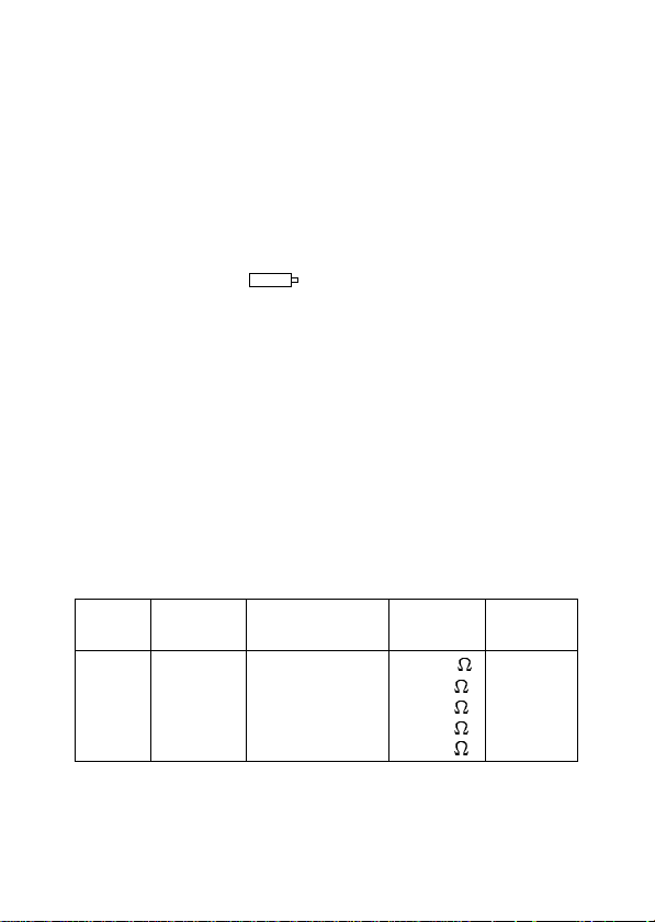
TENSIONS CONTINUES - Position VTENSIONS CONTINUES - Position V
TENSIONS CONTINUES - Position V
TENSIONS CONTINUES - Position VTENSIONS CONTINUES - Position V
Précision
±(n%L + mUR)*
200mV
2V
20V
200V
1 000V
100µV
1mV
10mV
100mV
1V
0,5%L + 4UR
0,8%L + 4UR
0,8%L + 4UR
0,8%L + 4UR
0,8%L + 4UR
DCDC
DC
DCDC
Résistance
d'entrée
>1000M
11M
10M
10M
10M
ProtectionRésolutionCalibre
1100V
CC
* L = lecture, UR = unité de représentation (CEI 485)
6
Page 12
MX 20
TENSIONS ALTERNATIVES - Position VTENSIONS ALTERNATIVES - Position V
TENSIONS ALTERNATIVES - Position V
TENSIONS ALTERNATIVES - Position VTENSIONS ALTERNATIVES - Position V
ACAC
AC
ACAC
Précision
±(n%L + mUR)*
Résistance
d'entrée
ProtectionRésolutionCalibre
(40Hz-500Hz)
2V
20V
200V
750V
1mV
10mV
100mV
1V
1%L + 8UR
1%L + 8UR
1%L + 8UR
1%L + 8UR
11 MW
10 MW
10 MW
10 MW
1100V
CC
· Spécifications applicables de 5% à 100% du calibre, pour un
signal sinusoïdal pur.
OHMMETREOHMMETRE
OHMMETRE
OHMMETREOHMMETRE
200 W
2 k W
20 kW
200 kW
2 MW
20 MW
0,1 W
1 W
10 W
100 W
1 k W
10 kW
Précision
±(n%L + mUR)*
0,8%L + 4UR
0,8%L + 4UR
0,8%L + 4UR
0,8%L + 4UR
1%L + 4UR
3%L + 4UR
Tension
à vide
430mV
"
"
"
"
"
ProtectionRésolutionCalibre
380V
AC
"
"
"
"
"
* L=lecture, UR=unité de représentation (CEI 485)
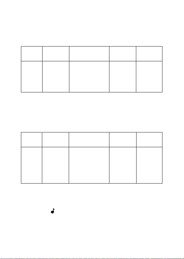
TEST DE CONTINUITETEST DE CONTINUITE
TEST DE CONTINUITE
TEST DE CONTINUITETEST DE CONTINUITE
· En position , mesure sur calibre 2 k W et alarme sonore quand
la résistance est inférieure à environ 1000 W
· Protection : 380V
AC
7
Page 13
MX 20
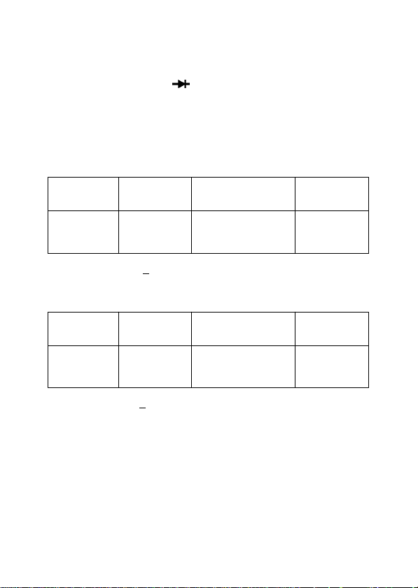
TEST DIODE - Position TEST DIODE - Position
TEST DIODE - Position
TEST DIODE - Position TEST DIODE - Position
· Affichage de la tension de seuil dans le sens passant, test bon/
mauvais. (tension max. affichée: 1,2 à 1,8V)
· Protection : 380V
COURANTS CONTINUSCOURANTS CONTINUS
COURANTS CONTINUS
COURANTS CONTINUSCOURANTS CONTINUS
Calibr e
20mA
200mA
10A
Chute de tension : < 500mV Protection : 250V
COURANTS ALTERNATIFS (40 à 500Hz)COURANTS ALTERNATIFS (40 à 500Hz)
COURANTS ALTERNATIFS (40 à 500Hz)
COURANTS ALTERNATIFS (40 à 500Hz)COURANTS ALTERNATIFS (40 à 500Hz)
pendant 1min. max.
AC/DC
Résolution
10µA
100µA
10mA
Précision
±(n%L + mUR)*
1,2%L + 1UR
1,2%L + 1UR
1,5%L + 1UR
Protection
(fusibles)
0,63A
0,63A
10A
AC
Calibr e
20mA
200mA
10A
Résolution
10µA
100µA
10mA
Précision
±(n%L + mUR)*
1,5%L + 8UR
1,5%L + 8UR
2%L + 8UR
Chute de tension: < 500mV Protection : 250V
Protection
(fusibles)
0,63A
0,63A
10A
AC
* L=lecture, UR=unité de représentation (CEI 485)
MEMORISATIONMEMORISATION
MEMORISATION
MEMORISATIONMEMORISATION
Lorsqu'une mesure vient d'être effectuée et qu'on appuie sur la
touche DATA HOLD, l'affichage est "figé" jusqu'à un nouvel appui
sur cette touche.
8
Page 14

MX 20
CHANGEMENT DE CALIBRECHANGEMENT DE CALIBRE
CHANGEMENT DE CALIBRE
CHANGEMENT DE CALIBRECHANGEMENT DE CALIBRE
· En mesures de tensions et en Ohmmètre, le multimètre fonctionne normalement en changement de calibre automatique; un
signal sonore se fait entendre à chaque changement de calibre
dans le sens croissant. Il est possible de sélectionner manuellement un calibre à l'aide de la touche MAN RANGE / AUTO RANGE.
· Un premier appui sur cette touche fige le calibre en cours, et
sélectionne le mode manuel. Les actions successives (brèves) sur
la touche incrémentent les calibres, et si la touche est maintenue
enfoncée durant plus de 2s, le multimètre repasse en mode
automatique.
2.3 ACCESSOIRES2.3 ACCESSOIRES
2.3 ACCESSOIRES
2.3 ACCESSOIRES2.3 ACCESSOIRES
Livrés avec le multimètre:Livrés avec le multimètre:
Livrés avec le multimètre:
Livrés avec le multimètre:Livrés avec le multimètre:
1 jeu de cordons - pointes de touche de sécurité AG0475
2 piles 1,5V R6 AL0008
1 fusible 6.3 x 32 - 10A - 50kA/600V AT0084
1 fusible 5 x 20 - 0,63A/250V - rapide 1,5kA/250V AT0047
1 notice de fonctionnement IM0822
Livrés en option:Livrés en option:
Livrés en option:
Livrés en option:Livrés en option:
Sondes:
HT0203 THT 3kV AC/DC
HT0212 THT 30kV DC
HT0208 HF 100kHz à 750MHz
HA0902 TV (suppresseur de transitoires HT)
HA1159 Thermomètre 1mV/°C, -50°C à +150°C
HK0210 Thermocouple type K, 1mV/°C, usage général et
HA1237 Tachymètre optique, 100t/mn à 60 000t/mn
surface, -25°C à +350°C.
9
Page 15

Pinces ampèremétriques :
AM0012 1 A à 400A AC, ouverture 15 mm
AM0014 10A à 200A AC, ouverture 15 mm
AM0015 1 A à 1 000A AC, ouverture 50 mm
AM0016 1 A à 600A AC, ouverture 15 mm
AM1000 1 A à 1 000A DC, 600A AC jusqu'à 600Hz
Shunts :
HA0171 30A DC / 300mV, ±0,5%
HA0512 50A DC / 50mV, ±0,5%
HA0300 300A DC / 30mV, ±0,5%
Divers :
MC0160 Gaine de protection
MC0159 Poignée détachable
AE0193 Etui de transport
MX 20
10
Page 16

MX 20
3 - MODE D'EMPLOI3 - MODE D'EMPLOI
3 - MODE D'EMPLOI
3 - MODE D'EMPLOI3 - MODE D'EMPLOI
3.1 PRESCRIPTIONS DE SECURITE3.1 PRESCRIPTIONS DE SECURITE
3.1 PRESCRIPTIONS DE SECURITE
3.1 PRESCRIPTIONS DE SECURITE3.1 PRESCRIPTIONS DE SECURITE
L'utilisation de ce multimètre implique de la part de l'utilisateur le
respect des règles de sécurité habituelles permettant de se
protéger contre les dangers du courant électrique et de préserver
le multimètre contre toute fausse manoeuvre qui pourrait lui être
fatale.
Les cordons de mesure doivent être en bon état et devront être
changés si leur isolement apparaît défectueux (isolant coupé,
brûlé...). Seuls les cordons livrés avec l'appareil garantissent le
respect des normes de sécurité, et ils devront être remplacés le cas
échéant par un modèle identique.
Ne jamais dépasser les valeurs limites de protection indiquées
dans les spécifications.
Avant d'ouvrir l'instrument pour un échange de fusible ou de pile,
s'assurer impérativement que les cordons de mesure sont déconnectés de toute source de courant électrique. Les fusibles de
remplacement doivent être d'un modèle et d'un type identique aux
fusibles d'origine (voir caractéristiques paragraphe 2.3).
ATTENTIONATTENTION
ATTENTION
ATTENTIONATTENTION
Lorsque l'ordre de grandeur de la valeur mesurée n'est pas connu,
s'assurer que le calibre de mesure de départ est le plus élevé
possible, ou choisir le mode de changement automatique des
calibres. Avant de changer de fonction, débrancher les cordons de
Si l'affichage reste à 0 quand on mesure uneSi l'affichage reste à 0 quand on mesure une
Si l'affichage reste à 0 quand on mesure une
Si l'affichage reste à 0 quand on mesure uneSi l'affichage reste à 0 quand on mesure une
tension non nulle, vérifier immédiatementtension non nulle, vérifier immédiatement
tension non nulle, vérifier immédiatement
tension non nulle, vérifier immédiatementtension non nulle, vérifier immédiatement
l'état du fusible 10 A (voir chapitre 4).l'état du fusible 10 A (voir chapitre 4).
l'état du fusible 10 A (voir chapitre 4).
l'état du fusible 10 A (voir chapitre 4).l'état du fusible 10 A (voir chapitre 4).
11
Page 17

MX 20
mesure du circuit mesuré. Lorsqu'on effectue des mesures de
courant, ne jamais changer de calibre, ne pas brancher ou débrancher les cordons sans que le courant n'ait été coupé au préalable.
De telles manoeuvres risqueraient de créer des extra-courants de
rupture ou de fermeture pouvant faire sauter inutilement les
fusibles ou endommager le commutateur ou les fiches et bornes de
mesure.
En dépannage TV, ou lors de mesures sur des circuits de commutation de puissance (Alimentations à découpage, circuits à thyristors et triacs, etc...), des impulsions de tension de forte amplitude
peuvent exister sur les points de mesure et endommager le
multimètre. L'utilisation d'une sonde de filtrage TV type HA0902
permet d'atténuer ces impulsions, et ainsi de protéger le multimètre.
Ne jamais effectuer de mesure de résistances sur un circuit sous
tension.
3.2 VERRROUILLAGE DES CORDONS DE MESURE3.2 VERRROUILLAGE DES CORDONS DE MESURE
3.2 VERRROUILLAGE DES CORDONS DE MESURE
3.2 VERRROUILLAGE DES CORDONS DE MESURE3.2 VERRROUILLAGE DES CORDONS DE MESURE
Le multimètre MX 20 est doté d'un système breveté ("SECUR'X")
qui interdit tout désenfichage accidentel des cordons de mesure de
ses bornes, renforçant ainsi la sécurité d'utilisation assurée par
ailleurs par l'emploi de cordons protégés. Le mécanisme SECUR'X
n'est pas intégré au boîtier, et peut être enlevé si nécessaire, en
particulier pour accéder au boîtier piles / fusibles.
Ce système, d'utilisation très simple, permet l'insertion sans effort
de la fiche banane. Le blocage est assuré par la présence de
rainures sur le corps des fiches.
Pour déverrouiller, pousser la languette vers l'appareil et tirer sur
la fiche.
12
Page 18

MX 20
3.3 MISE EN PLACE DES PILES - ACCES AUX FUSIBLES3.3 MISE EN PLACE DES PILES - ACCES AUX FUSIBLES
3.3 MISE EN PLACE DES PILES - ACCES AUX FUSIBLES
3.3 MISE EN PLACE DES PILES - ACCES AUX FUSIBLES3.3 MISE EN PLACE DES PILES - ACCES AUX FUSIBLES
Le boîtier étanche (vis à vis de l'extérieur autant que de l'intérieur
de l'appareil) est situé sous le plastron amovible du multimètre.
Pour y accéder:
- Oter le système SECUR'X après l'avoir déverrouillé en engageant
un pied de la bequille de l'appareil sur les côtés. Les cordons de
mesure doivent donc obligatoirement avoir été déconnectés.
- Déverrouiller le plastron de l'appareil en engageant un outil
adéquat (la béquille de l'appareil est prévue à cet usage) sur les
côtés (points repérés par des flèches sur le plastron) et en exerçant
une pression modérée.
Voir vue éclatée en fin de notice.
Respecter la polarité indiquée par les signes + et - en connectant
les piles, et remettre en place le plastron en veillant à ce que le joint
d'étanchéité soit resté propre (absence de particules solides, sable
ou autres à sa surface) et soit positionné correctement, encliqueter
enfin le SECUR'X en place.
3.4 MISE EN SERVICE3.4 MISE EN SERVICE
3.4 MISE EN SERVICE
3.4 MISE EN SERVICE3.4 MISE EN SERVICE
· Positionner le commutateur rotatif du multimètre sur la fonction de
mesure choisie, il se mettra en service dès que le commutateur
aura quitté la position OFF.
3.4.1 CHANGEMENT DE CALIBRE AUTO/MAN3.4.1 CHANGEMENT DE CALIBRE AUTO/MAN
3.4.1 CHANGEMENT DE CALIBRE AUTO/MAN
3.4.1 CHANGEMENT DE CALIBRE AUTO/MAN3.4.1 CHANGEMENT DE CALIBRE AUTO/MAN
· En fonction Voltmètre et Ohmmètre, le multimètre démarre en
mode changement de calibre automatique. Il est conseillé de ne
passer en mode manuel qu’après avoir situé l’ordre de grandeur de
la mesure en mode automatique.
13
Page 19

MX 20
ATTENTION : en mesure de courants, la commutation est tou-
jours manuelle, et la sélection s’effectue par le
commutateur rotatif. Voir particulièrement les précautions à respecter au chapitre des mesures de
courant.
· Une action sur la touche MAN RANGE / AUTO RANGE permet
le passage en mode manuel, et la valeur du calibre peut alors être
modifiée pas à pas dans le sens croîssant, en pressant la même
touche brièvement
· Une pression de plus de 2 secondes
..
.
..
sur la touche MAN RANGE
/ AUTO RANGE provoque le retour du multimètre en mode AUTO.
3.4.2 MESURE DES TENSIONS CONTINUES3.4.2 MESURE DES TENSIONS CONTINUES
3.4.2 MESURE DES TENSIONS CONTINUES
3.4.2 MESURE DES TENSIONS CONTINUES3.4.2 MESURE DES TENSIONS CONTINUES
· Brancher le cordon noir à la borne COM, et le cordon rouge à la
borne V .
· Amener le commutateur rotatif à la position V
· Amener les pointes de touche aux points de mesure de tension,
.
DC.
et lire le résultat directement sur l’afficheur. L’unité de mesure (mV
ou V) ainsi que la polarité ( - pour négatif, rien pour positif) sont
également affichés.
· Précision, résolution et résistance d’entrée: voir spécifications
§ 2.2.
ATTENTION : ne jamais dépasser une tension de 1 000 V conti-
nus ou 750 V alternatifs, et en présence de signaux impulsionnels (par exemple sur les circuits
lignes des téléviseurs), utiliser une sonde de filtrage type HA0902. (Voir § 3.1)
14
Page 20

MX 20
· En circuit ouvert sur le calibre 200mV DC (à haute impédance), un
affichage peut être constaté, et éventuellement un dépassement,
signalé par un bip sonore. Ce phénomène est normal, et n'affecte
pas le fonctionnement du multimètre.
· En mode manuel, si l’afficheur indique un "1 " clignotant, le calibre
utilisé est trop faible, il y a «dépassement». Passer au calibre
supérieur à l’aide de la touche RANGE / AUTO (un appui < 2s).
Mesures de tensions supérieures à 1 000 VMesures de tensions supérieures à 1 000 V
Mesures de tensions supérieures à 1 000 V
Mesures de tensions supérieures à 1 000 VMesures de tensions supérieures à 1 000 V
Ces mesure sont possibles en utilisant des sondes réductrices.
ATTENTION : la mesure de tensions élevées requiert certaines
précautions.
*S'assurer que la sonde utilisée est propre et en parfait
état, sans craquelure de l'isolant constituant le corps.
* Procéder autant que possible dans un lieu sec, sur un
tapis isolant.
* Pendant la mesure, éviter de toucher toute partie métallique pouvant être réunie à la terre.
15
Page 21

MX 20
3.4.3 MESURE DE TENSIONS ALTERNATIVES3.4.3 MESURE DE TENSIONS ALTERNATIVES
3.4.3 MESURE DE TENSIONS ALTERNATIVES
3.4.3 MESURE DE TENSIONS ALTERNATIVES3.4.3 MESURE DE TENSIONS ALTERNATIVES
· Brancher le cordon noir à la borne COM, et le cordon rouge à la
borne VW .
· Amener le commutateur rotatif à la position VAC,
· Amener les pointes de touche aux points de mesure de tension,
et lire le résultat directement sur l’afficheur. L’unité de mesure (mV
ou V) est également affichée.
· Précision, résolution et résistance d’entrée: voir spécifications.
ATTENTION : ne jamais dépasser une tension de 1 000 V conti-
nus ou 750 V alternatifs, et en présence de signaux impulsionnels (par exemple sur les circuits
lignes des téléviseurs), utiliser une sonde de fil
trage type HA0902.
· En mode manuel, si l’afficheur indique un "1" clignotant, le calibre
utilisé est trop faible, il y a «dépassement». Passer au calibre
supérieur à l’aide de la touche MAN RANGE/AUTO RANGE.
3.4.4 MESURE DES RESISTANCES ET CONTROLE DES3.4.4 MESURE DES RESISTANCES ET CONTROLE DES
3.4.4 MESURE DES RESISTANCES ET CONTROLE DES
3.4.4 MESURE DES RESISTANCES ET CONTROLE DES3.4.4 MESURE DES RESISTANCES ET CONTROLE DES
DIODESDIODES
DIODES
DIODESDIODES
· La mesure des résistances, comme la mesure des tensions, peut
être effectuée en sélection automatique ou manuelle des calibres
(Voir utilisation de la touche MAN RANGE/AUTO RANGE au
chapitre 3.4.1)
· Relier le cordon noir à la borne COM et le cordon rouge à la borne
V W du multimètre, et positionner le commutateur rotatif sur W .
16
Page 22

MX 20
·Tant que les cordons ne sont ni court-circuités ni reliés à une
résistance, l’afficheur indique un dépassement.
· Ne jamais effectuer de mesure de résistance sur un circuit sous
tension.
· Pour la mesure des résistances de valeurs élevées (calibre
2 0 M W ), certaines précautions peuvent s’avérer nécessaires: utilisation de cables blindés, blindage de la résistance à mesurer etc...
En effet, en raison de la rapidité d’acquisition du multimètre, la
mesure peut être perturbée et rendue instable par des parasites
électriques ou électrostatiques.
Test rapide de continuité (beep sonore)Test rapide de continuité (beep sonore)
Test rapide de continuité (beep sonore)
Test rapide de continuité (beep sonore)Test rapide de continuité (beep sonore)
· Positionner le commutateur sur .
· Le multimètre fonctionne comme sur le calibre 2kW de l'ohmmètre, et le signal sonore retentira dès que la resistance du circuit
mesuré sera inférieure à environ 1000W .
Contrôle des diodesContrôle des diodes
Contrôle des diodes
Contrôle des diodesContrôle des diodes
· Le principe de la mesure consiste à injecter dans la jonction à
tester un courant donné et à lire la chute de tension produite à ses
bornes.
· Brancher le cordon noir à la borne COM et le cordon rouge à la
borne VW , e t amener la flèche du commutateur à la position .
· Sur une jonction en inverse ou pour une un circuit ouvert,
l’afficheur indiquera de 1,200 à 1,800V.
· Comme dans le cas des mesures de résistances, ce test ne doit
jamais s’effectuer sur un circuit sous tension.
17
Page 23

MX 20
3.4.5 MESURE DES COURANTS CONTINUS3.4.5 MESURE DES COURANTS CONTINUS
3.4.5 MESURE DES COURANTS CONTINUS
3.4.5 MESURE DES COURANTS CONTINUS3.4.5 MESURE DES COURANTS CONTINUS
- La mesure des courants ne s’effectue pas en mode de changement de calibre automatique.
- Relier le cordon noir à la borne COM et le cordon rouge soit à la
borne mA pour mesurer des courants < 200 mA, soit à la borne A
pour mesurer des courants jusqu’à 10 A.
- Il est conseillé de choisir au départ le calibre le plus élevé possible
(10A), lorsque l’ordre de grandeur du courant à mesurer n’est pas
connu. Pour ce faire, amener le commutateur rotatif à la position
10A correspondante et choisir la borne d'entrée 10A.
· Ne relier le multimètre en série dans le circuit à mesurer qu’au
dernier moment, et enfin mettre en service le circuit à mesurer.
· Si le calibre choisi est trop élevé, couper d’abord l’alimentation du
circuit mesuré, ensuite changer la position du commutateur rotatif
et la borne d'entrée, et remettre le circuit en service.
Ne jamais changer de calibre en cours de mesure, ni déconnecter
les cordons de mesure: des extra-courants de commutation et des
surtensions peuvent prendre naissance, qui risquent d’endommager le multimètre ou de provoquer des ruptures intempestives des
fusibles.
· Afin de limiter tout échauffement et d’éviter les dérives thermiques, il est conseillé de limiter le temps de mesure des courants
forts (10A) à quelques dizaines de secondes.
3.4.6 MESURE DES COURANTS ALTERNATIFS3.4.6 MESURE DES COURANTS ALTERNATIFS
3.4.6 MESURE DES COURANTS ALTERNATIFS
3.4.6 MESURE DES COURANTS ALTERNATIFS3.4.6 MESURE DES COURANTS ALTERNATIFS
· La mesure des courants ne s’effectue pas en mode de changement de calibre automatique.
18
Page 24

MX 20
· Relier le cordon noir à la borne COM et le cordon rouge soit à la
borne mA pour mesurer des courants < 200mA, soit à la borne A
pour mesurer des courants jusqu’à 10 A.
· Il est conseillé de choisir au départ le calibre le plus élevé possible
(10 A), lorsque l’ordre de grandeur du courant à mesurer n’est pas
connu.
· Ne relier le multimètre en série dans le circuit à mesurer qu’au
dernier moment, et enfin mettre en service le circuit à mesurer.
· Si le calibre choisi est trop élevé, couper d’abord l’alimentation du
circuit mesuré, ensuite changer la position du commutateur rotatif
et remettre le circuit en service.
· Ne jamais changer de calibre en cours de mesure, ni déconnecter
les cordons de mesure: des extra-courants de commutation et des
surtensions peuvent prendre naissance, qui risquent d’endommager le multimètre ou de provoquer des ruptures intempestives des
fusibles.
· Afin de limiter tout échauffement et d’éviter les dérives thermiques, il est conseillé de limiter le temps de mesure des courants
forts (5 A et 10 A) à quelques dizaines de secondes.
3.4.7 MEMORISATION DES MESURES3.4.7 MEMORISATION DES MESURES
3.4.7 MEMORISATION DES MESURES
3.4.7 MEMORISATION DES MESURES3.4.7 MEMORISATION DES MESURES
· La touche DATA HOLD donne accès au mode mémoire pour les
fonctions "conventionnelles" (Voltmètre, Ampèremètre, Ohmmètre) du multimètre.
· Un premier appui sur cette touche "fige" la valeur numérique
affichée. Un deuxième appui efface l'affichage et permet d'effectuer une nouvelle mesure.
19
Page 25

MX 20
4. ENTRETIEN4. ENTRETIEN
4. ENTRETIEN
4. ENTRETIEN4. ENTRETIEN
Les réglages réalisés en usine n'ont pas à être repris, sauf en cas
de dépannage (hors période de garantie) éventuellement entrepris
par l'utilisateur, ou de procédure de contrôle périodique (annuel).
4.1 PILES4.1 PILES
4.1 PILES
4.1 PILES4.1 PILES
Le multimètre ne doit pas subir de stockage prolongé sans que ses
piles n'aient été préalablement enlevées de leur boitier étanche. En
effet, celles-ci risqueraient, à terme, de produire une oxydation de
ses points de contact, voire de les détériorer.
Lorsque les piles sont usée le signe apparaît sur l'afficheur. Pour échange de la pile, voir § 3.3.
4.2 FUSIBLES4.2 FUSIBLES
4.2 FUSIBLES
4.2 FUSIBLES4.2 FUSIBLES
Les fusibles doivent impérativement être remplacés quand nécessaire par des fusibles rigoureusement équivalents aux fusibles
d'origine.
Il est bon, en cas de rupture d'un fusible, d'en déterminer la cause
qui pourrait, si elle se reproduisait, endommager l'instrument à la
longue, et d'y remédier (fausse manoeuvre en particulier).
20
- +
Page 26

MX 20
JOINT
SECUR'X
PLASTRON
BOITIER
Vue éclatée - accès au boitier pile / fusiblesVue éclatée - accès au boitier pile / fusibles
Vue éclatée - accès au boitier pile / fusibles
Vue éclatée - accès au boitier pile / fusiblesVue éclatée - accès au boitier pile / fusibles
21
Page 27

MX 20
NF-C 15 100 / NF-C 18510 / NF-C 18530
WARNING
Hazardous voltages are present in this electrical
equipment during operation.
Non observance of the safety instructions can result in
severe personal injury or property damage.
Only qualified personnel should work on or around this
equipment after becoming thoroughly familiar
with all warnings, safety notices, and maintenance
procedures contained herein.
The successful and safe operation of this equipment is
dependant on proper handling, installation,
operation and maintenance.
Qualified person :
A "qualified person" is one who is familiar with the installation, construction and operation of the equipment and
the hazards involved.
In addition, he has the following qualifications :
· He is trained and authorized to energize, de-energize,
clear, ground and tag circuits and equipment in accordance
with established practices.
· He is trained in the proper care and use of protective
equipment in accordance with established safety practices.
· He is trained in rendering first aid.
IEC 364
22
Page 28

MX 20
SAFETYSAFETY
SAFETY
SAFETYSAFETY
This instrument has been constructed and tested according to the
IEC 1010 - Class 2 standard. It agrees with the EEC 73/23 low
voltage European Directive, amended by EEC 93/68.
This manual contains information and advice which users must
follow to ensure the reliability of the multimeter and to keep it in
good condition with regard to safety.
The instrument may occasionally be exposed to temperatures
between 0°C and -10°C without its safety features being compromised. It should not be used at altitudes above 2000 metres.
Taking measurements - MaintenanceTaking measurements - Maintenance
Taking measurements - Maintenance
Taking measurements - MaintenanceTaking measurements - Maintenance
When the instrument is connected to a circuit under test, some of
its terminals may be hazardous, and opening the case may provide
access to parts which are hazardous if touched.
Therefore:
- Keep fingers away from unused terminals.
- Disconnect the multimeter from any form of measurement input
before opening it for adjustment, replacement of fuses or battery,
or any kind of maintenance or repair work.
CautionCaution
Caution
CautionCaution
- The multimeter contains capacitors which may remain charged
even after it has been disconnected from all voltage sources.
23
Page 29

MX 20
- The instrument should not be opened up for adjustment, maintenance or repair when live unless this is absolutely essential, in
which case, the work should be carried out only by appropriately
qualified personnel advised of the risk involved.
- Replacement fuses must be of the appropriate type and rating
(see Accessories section 2.3).
The use of makeshift fuses and short-circuiting of the fuseholder
contacts are strictly prohibited.
FAULTS AND ABNORMAL CONSTRAINTSFAULTS AND ABNORMAL CONSTRAINTS
FAULTS AND ABNORMAL CONSTRAINTS
FAULTS AND ABNORMAL CONSTRAINTSFAULTS AND ABNORMAL CONSTRAINTS
Should there be any indication that the protection of the instrument
has been compromised, it should be taken out of service to prevent
it being used inadvertently.
Protection may have been compromised in the following cases:
- The instrument is obviously damaged.
- The instrument is no longer capable of taking accurate measurements.
- The instrument has been stored under unfavourable conditions.
- The instrument has been subject to severe stresses during
transport.
SYMBOLSYMBOL
SYMBOL
SYMBOLSYMBOL
The symbol refers the user to the Instruction Manual. The user
should consult the manual and proceed accordingly.
24
Page 30

MX 20
1 - INTRODUCTION1 - INTRODUCTION
1 - INTRODUCTION
1 - INTRODUCTION1 - INTRODUCTION
The MX 20 Digital Multimeter is a self-contained, handled instrument for professional use, designed for routine electrical and
electronic measurements such as AC and DC voltage and current,
resistance, and diode and logic checks. It has a memory function
capable of storing current measured values.
The casing is completely sealed (to IP 66 standard), and particular
attention has been paid to protecting both user and instrument in
the event of misuse. Access to the battery and fuse compartment
is impossible without first disconnecting the test leads (patented
SECUR’X latching), and all ranges and functions are thoroughly
protected against overload.
Power is supplied by two 1.5V batteries providing 250 h normal
use.
Measurement functions are selected using a rotary switch, and the
various operating modes are accessed via two keys
25
Page 31

MX 20
2 - TECHNICAL SPECIFICATIONS2 - TECHNICAL SPECIFICATIONS
2 - TECHNICAL SPECIFICATIONS
2 - TECHNICAL SPECIFICATIONS2 - TECHNICAL SPECIFICATIONS
Only values for which tolerances or limits are specified should be
considered as guaranteed values.
Values without tolerances are given for information only (French
standard NF C 42 670).
2.1 - GENERAL SPECIFICATIONS2.1 - GENERAL SPECIFICATIONS
2.1 - GENERAL SPECIFICATIONS
2.1 - GENERAL SPECIFICATIONS2.1 - GENERAL SPECIFICATIONS
SAFETYSAFETY
SAFETY
SAFETYSAFETY
Conforms to IEC 1010-1 class 2
Casing and circuits : self-extinguishing materials.
ENVIRONMENTENVIRONMENT
ENVIRONMENT
ENVIRONMENTENVIRONMENT
- Reference Temperature: 18°C to 28°C
- Rated range of use: 0°C to +50°C
- Storage temperature -45°C to +80°C
POWER SUPPLYPOWER SUPPLY
POWER SUPPLY
POWER SUPPLYPOWER SUPPLY
Two 1.5V batterie, R6 size.
Battery life : typically 250 hours of continuous service.
Pollution degree 2
Overvoltage category CAT II 600 V
CAT I 1000 V
Indoor use, altitude < 2000 m
Insulation class 2
R.H. <75%
R.H. <80%
R.H. <70%
DIMENSIONSDIMENSIONS
DIMENSIONS 189 x 82 x 40 mm
DIMENSIONSDIMENSIONS
WEIGHTWEIGHT
WEIGHT 400g approx.
WEIGHTWEIGHT
26
Page 32

MX 20
DISPLAYDISPLAY
DISPLAY
DISPLAYDISPLAY
± 1999 points
- 7-segment liquid crystal display
- Digit height : 17mm
- Indicators for measuring function, function mode, and unit of
measurement.
- Overshoot indicated by display showing «1 »
- +
- symbol indicates battery low.
- Continuity test: symbol and optional buzzer.
MEASUREMENT RATEMEASUREMENT RATE
MEASUREMENT RATE
MEASUREMENT RATEMEASUREMENT RATE
2 measurements/s
RANGINGRANGING
RANGING
RANGINGRANGING
Automatic or manual for voltage and resistance measurements,
manual for current measurements.
2.2 SPECIFICATIONS2.2 SPECIFICATIONS
2.2 SPECIFICATIONS
2.2 SPECIFICATIONS2.2 SPECIFICATIONS
DC VOLTAGE - VDC VOLTAGE - V
DC VOLTAGE - V
DC VOLTAGE - VDC VOLTAGE - V
200mV
2V
20V
200V
1 000V
100µV
1mV
10mV
100mV
1V
positions positions
positions
positions positions
DCDC
DC
DCDC
Accuracy
±(n%R + mC)*
0,5%R + 4C
0,8%R + 4C
0,8%R + 4C
0,8%R + 4C
0,8%R + 4C
* R=reading; C=count
Input
resistance
>1000M
11M
10M
10M
10M
ProtectionResolutionRange
1100V
PP
27
Page 33

MX 20
AC VOLTAGE - VAC VOLTAGE - V
AC VOLTAGE - V
AC VOLTAGE - VAC VOLTAGE - V
positions positions
positions
positions positions
ACAC
AC
ACAC
±(n%R + mC)*
Accuracy
Input
resistance
ProtectionResolutionRange
(40Hz-500Hz)
2V
20V
200V
750V
OHMMETEROHMMETER
OHMMETER
OHMMETEROHMMETER
1mV
10mV
100mV
1V
1%R + 8C
1%R + 8C
1%R + 8C
1%R + 8C
11MW
10MW
10MW
10MW
1100V
PP
·Specifications applicable from 5% to 100% of the range, for a pure
sinusoidal signal.
200W
2kW
20kW
200kW
2MW
20MW
0,1 W
1W
10W
100W
1kW
10kW
Accuracy
±(n%R + mC)*
0,8%R + 4C
0,8%R + 4C
0,8%R + 4C
0,8%R + 4C
1%R + 4C
3%R + 4C
o. c.
Voltage
430mV
"
"
"
"
"
ProtectionResolutionRange
380V
AC
"
"
"
"
"
* R = Reading, C = Counts
·Pressing the key marked activates the test buzzer. On the kW
range, check if R < 1000W approx.
·Protection : 380V
AC
28
Page 34
MX 20
DIODE CHECK settingDIODE CHECK setting
DIODE CHECK setting
DIODE CHECK settingDIODE CHECK setting
· Indication of threshold voltage in the forward direction. Go - No
go test (max. displayed voltage: 1.2 to 1.8V).
· Protection: 380VAC / 1min max.
DC CURRENTDC CURRENT
DC CURRENT
DC CURRENTDC CURRENT
Range
20mA
200mA
10A
Resolution
10µA
100µA
10mA
Accuracy
±(n%R + mC)*
1,2%R + 1C
1,2%R + 1C
1,5%R + 1C
Voltage burden : < 500mV Protection : 250V
AC CURRENTAC CURRENT
AC CURRENT
AC CURRENTAC CURRENT
Range
20mA
200mA
10A
Resolution
10µA
100µA
10mA
Accuracy
±(n%R + mC)*
1,5%R + 8C
1,5%R + 8C
2%R + 8C
Voltage burden : < 500mV Protection : 250V
Protection
(fuses)
0.63A
0.63A
10A
AC
Protection
(fuses)
0.63A
0.63A
10A
AC
* R = Reading, C = Counts
MEMORYMEMORY
MEMORY
MEMORYMEMORY
· When a measurement has been carried out, depressing the DATA
HOLD key will "freeze" the display until the key is depressed again.
29
Page 35

MX 20
RANGINGRANGING
RANGING
RANGINGRANGING
· In voltage and resistance measurements, the multimeter normally
operates in automatic ranging mode; an audible signal is heard
every time the range increases. Ranges can be selected manually
by pressing the MAN RANGE/AUTO RANGE key.
· Pressing the key once fixes the current range (manual mode).
Each brief touch of the key increments the range, and if the key is
held down for more than two seconds, the multimeter returns to
automatic ranging mode.
2.3 - ACCESSORIES2.3 - ACCESSORIES
2.3 - ACCESSORIES
2.3 - ACCESSORIES2.3 - ACCESSORIES
Supplied with the multimeterSupplied with the multimeter
Supplied with the multimeter
Supplied with the multimeterSupplied with the multimeter
One set of test leads and safety prods AG0475
Two 1.5 R6 size batteries AL0020
One 10 A fuse, 6.3x32mm, 50kA/600V AT0084
One 0.63 A fuse, 5 x 20 mm, fast-blow, 1.5kA/250V AT0047
One Instruction Manual IM0822
OptionalOptional
Optional
OptionalOptional
Probes :
HT0203 EHT 3 kV AC/DC
HT0212 EHT 30 kV DC
HT0208 RF 100 kHz to 750 MHz
HA0902 TV (HT transient suppressor)
HA1159 Thermometer, 1 mV/°C, -50°C to +150°C
HK0210 Type K thermocouple, 1mV/°C, general purpose
HA1237 Optical tachometer, 100 rpm to 60000 rpm
and surface type, -25°C to + 350°C.
30
Page 36

MX 20
Current clamp-on :
AM0012 1 A to 200 AAC, opens to 15 mm
AM0015 1 A to 1000 AAC, opens to 50 mm
HA0768 1A to 1000 AAC, opens to 100 mm
AM1000 1 A t o 1000 ADC, 600 A AC to 600 Hz
Shunts :
HA0171 30ADC/300mV, ± 0.5%
HA0512 50ADC/50mV, ± 0.5%
HA0300 300ADC/30mV, ± 0.5%
Miscellaneous :
MC0160 Shock absorber
MC0159 Detachable handle
AE0193 Carrying case
31
Page 37

MX 20
3 - OPERATING INSTRUCTIONS3 - OPERATING INSTRUCTIONS
3 - OPERATING INSTRUCTIONS
3 - OPERATING INSTRUCTIONS3 - OPERATING INSTRUCTIONS
3.1 - SAFETY PRECAUTIONS3.1 - SAFETY PRECAUTIONS
3.1 - SAFETY PRECAUTIONS
3.1 - SAFETY PRECAUTIONS3.1 - SAFETY PRECAUTIONS
Use of this multimeter implies respect for the usual safety rules
designed to protect the user against electrical hazards and to
protect the instrument against damage resulting from misuse.
The test leads and mains supply lead must be in good condition and
should be changed if there is any evidence of deterioration
(insulation burnt or split etc.). Only the leads supplied with the
instrument are guaranteed to meet safety standards. If necessary
they should be replaced by identical leads.
The maximum values indicated in these specifications should not
under any circumstances be exceeded.
Before opening up the instrument to replace the battery or fuses,
users must check that the test leads are disconnected from all
electrical current sources. Replacement fuses must be of the
same type and rating as the original fuses (see Specifications,
section 2.3).
CautionCaution
Caution
CautionCaution
If the order of magnitude of the quantity being measured is
unknown, begin with the highest range or select autoranging mode.
Disconnect the test leads from the circuit under test before
changing the measurement function. When measuring currents,
the range should not be changed and the leads should not be
plugged in or unplugged without first switching off the current.
32
If the display continues to read zero whenIf the display continues to read zero when
If the display continues to read zero when
If the display continues to read zero whenIf the display continues to read zero when
measuring a non-zero voltage, check the 10Ameasuring a non-zero voltage, check the 10A
measuring a non-zero voltage, check the 10A
measuring a non-zero voltage, check the 10Ameasuring a non-zero voltage, check the 10A
fuse immediately (see section 4).fuse immediately (see section 4).
fuse immediately (see section 4).
fuse immediately (see section 4).fuse immediately (see section 4).
Page 38

MX 20
Otherwise current surges may arise when the circuit is made or
broken and these could blow the fuses or damage the switch or the
sockets and terminals.
When checking out a television or power switching circuits (switched mode power supplies, circuits including thyristors and triacs,
etc.) high-amplitude voltage pulses at the test point may damage
the multimeter. The use of a TV filter probe, type HA0902, protects
the multimeter by attenuating any such pulses.
Resistance measurements should never be made on a live circuit.
3.2 - TEST LEAD LATCHING3.2 - TEST LEAD LATCHING
3.2 - TEST LEAD LATCHING
3.2 - TEST LEAD LATCHING3.2 - TEST LEAD LATCHING
The MX 20 multimeter features the patented SECUR’X system
which prevents inadvertant unplugging of the test leads, and adds
to the degree of protection already provided by the leads themselves. The SECUR’X system is not an integral part of the instrument
and can be removed if necessary, particularly for access to the
battery and fuses.
The system, which is extremely simple to use, permits effortless
insertion of the banana plug. The latching effect is obtained by
means of grooves on the plug body.
To unlatch a lead push the tab forwards and pull on the plug.
33
Page 39

MX 20
3.3 - BATTERIES INSTALLATION - FUSE REPLACEMENT3.3 - BATTERIES INSTALLATION - FUSE REPLACEMENT
3.3 - BATTERIES INSTALLATION - FUSE REPLACEMENT
3.3 - BATTERIES INSTALLATION - FUSE REPLACEMENT3.3 - BATTERIES INSTALLATION - FUSE REPLACEMENT
The sealed compartment (sealed from both inside and outside of
the instrument) is located under the removable protective cover.
To access the compartment:
- Unlatch the SECUR’X system by inserting the instrument
support strut in the sides and then remove it. This ensures that the
test leads are disconnected.
- Release the protective cover by inserting the instrument
support strut into the sides of the instrument (at the places marked
by the arrows) and by applying moderate pressure.
See exploded view at the end of the manual
Insert the battery, ensuring correct polarity by matching + and signs, and replace the cover making sure that the watertight seal
remains clean (no solid particles, grit or other particulates) and is
positioned correctly. Finally snap the SECUR’X system in place.
3.4 - SWITCHING ON3.4 - SWITCHING ON
3.4 - SWITCHING ON
3.4 - SWITCHING ON3.4 - SWITCHING ON
· Set the rotary switch to the required measurement function. The
instrument is then ready for use.
3.4.1 - AUTOMATIC/MANUAL RANGING3.4.1 - AUTOMATIC/MANUAL RANGING
3.4.1 - AUTOMATIC/MANUAL RANGING
3.4.1 - AUTOMATIC/MANUAL RANGING3.4.1 - AUTOMATIC/MANUAL RANGING
· When used as a voltmeter and ohmmeter, the instrument is in
autoranging mode when first switched on. Manual ranging is not
recommended unless the order of magnitude of the quantity to be
measured has first been determined in autoranging mode.
34
Page 40

MX 20
CAUTION In ammeter function, range switching is always
manual, and selected by the rotary switch.
See precautions to be observed in the current
measurement section.
· Pressing the MAN RANGE/AUTO RANGE key changes to the
manual ranging mode, and the range selected can then be incremented by briefly pressing the same key. (Hold it down for not more
than two seconds.)
· Holding the MAN RANGE/AUTO RANGE key down for more than
two seconds re-activates autoranging mode.
3.4.2 DC VOLTAGE MEASUREMENT3.4.2 DC VOLTAGE MEASUREMENT
3.4.2 DC VOLTAGE MEASUREMENT
3.4.2 DC VOLTAGE MEASUREMENT3.4.2 DC VOLTAGE MEASUREMENT
· Connect the black lead to the terminal marked COM, and the red
lead to the terminal marked VW .
· Set the rotary switch to the VDC position.
· Apply the test prods to the points across which the voltage is to
be measured, and read the result directly from the display. This
shows the measurement units (mV or V) and the polarity ( - for
negative polarity and nothing for positive polarity).
· Accuracy, resolution, and input resistance: see detail specifications section 2.2.
CAUTION Under no circumstances should a voltage excee
ding 1000VDC or 750VAC be applied to the instru
ment, and, where pulse signals are present (for
example in the line scanning circuits of television
sets), use a type HA0902 filter probe.
(See section 3.1).
35
Page 41

MX 20
· When in open circuit on the 200mV range (high impedance) the
instrument may display some value, and eventually an overflow
(beep). This does no affects the normal operation of the multimeter.
· In manual ranging mode, if the display shows «1 » blinking, the
range selected is too low. Switch to the next higher range by
pressing the RANGE/AUTO key (press once for less than 2
seconds)
Measuring voltages above 1000V:Measuring voltages above 1000V:
Measuring voltages above 1000V:
Measuring voltages above 1000V:Measuring voltages above 1000V:
Voltages above 1000V can be measured using a voltage-reducing
probe.
CAUTION The following precautions must be observed when
measuring high voltages:
* Check that the probe used is clean and in perfect condiiion, with no signs of cracking of the body’s insulating
material.
* If possible, high voltages should be measured only in a
dry place with an insulating floor covering.
* While making the measurement, avoid touching any
metal objects that might be earthed.
36
Page 42

MX 20
3.4.3 - AC VOLTAGE MEASUREMENT3.4.3 - AC VOLTAGE MEASUREMENT
3.4.3 - AC VOLTAGE MEASUREMENT
3.4.3 - AC VOLTAGE MEASUREMENT3.4.3 - AC VOLTAGE MEASUREMENT
· Connect the black lead to the terminal marked COM and the red
lead to the terminal marked VW .
· Set the rotary switch to the AC volts position.
· Apply the test prods to the points across which the voltage is to
be measured and read the result directly from the display. The
display also shows the unit of measurement (mV or V).
· Accuracy, resolution, and input resistance: see detail specifications.
CAUTION Under no circumstances should a voltage excee-
ding 1000VDC or 750VAC be applied to the instrument, and, where pulse signals are present (for
example in the line scanning circuits of television
sets), use a type HA0902 filter probe.
· In manual ranging mode, if the display shows «1 » the range
selected is too low. Switch to the next higher range by pressing the
MAN RANGE/AUTO RANGE key (press once for less than 2
seconds.)
3.4.4 RESISTANCE MEASUREMENT AND DIODE CHECKS3.4.4 RESISTANCE MEASUREMENT AND DIODE CHECKS
3.4.4 RESISTANCE MEASUREMENT AND DIODE CHECKS
3.4.4 RESISTANCE MEASUREMENT AND DIODE CHECKS3.4.4 RESISTANCE MEASUREMENT AND DIODE CHECKS
·Measuring resistance, like measuring voltage, can be carried out
in autoranging or manual modes (see use of the MAN RANGE/
AUTO RANGE key).
· Connect the black lead to the terminal marked COM and the red
lead to the terminal marked VW on the multimeter and set the rotary
switch to W .
37
Page 43

MX 20
· If the leads are not short-circuited or connected to a resistance,
the display indicates an out of limits condition «1 » blinking.
· Under no circumstances should resistance be measured on a live
circuit.
· Certain precautions may be necessary to measure high resistances (40Mohms range): use of screened cables, screening of the
resistance to be measured, etc. Because of the acquisition speed
of the multimeter, the measurement may be disturbed and made
unstable by electrical or electrostatic interference.
Quick continuity check (buzzer)Quick continuity check (buzzer)
Quick continuity check (buzzer)
Quick continuity check (buzzer)Quick continuity check (buzzer)
· Set the rotary switch to the position.
· The multimeter operates on the 2kW range, and an audible signal
will be heard when the measured circuit resistance is less than
1000 W approx.
Diode checkDiode check
Diode check
Diode checkDiode check
· The diode check entails injecting a given current into the diode
junction to be tested and reading the voltage drop across the diode.
· Connect the black lead to the COM terminal and the red lead to
the VW terminal and then set the rotary switch to the position.
· The display will indicate 1.2 to 1.8V if the diode junction is reverse
biased or if the circuit is open.
· Like resistance measurements, the diode check function must not
be used on a circuit that is live.
38
Page 44

MX 20
3.4.5 - DC CURRENT MEASUREMENT3.4.5 - DC CURRENT MEASUREMENT
3.4.5 - DC CURRENT MEASUREMENT
3.4.5 - DC CURRENT MEASUREMENT3.4.5 - DC CURRENT MEASUREMENT
· When used as an ammeter, the MX 20 is alawais in manual
ranging mode.
· Connect the black lead to the COM terminal and the red lead to
the mA terminal for measuring currents less than 200mA or to the
A terminal for measuring currents up to 10A.
· It is best to begin by selecting the highest possible range (10A)
when the order of magnitude of the current to be measured is
unknown. In this case set the rotary switch to the corresponding
A position and select the A input terminal.
· If necessary, press the AC/DC key to display the DC symbol.
· Do not connect the multimeter in series with the circuit to be
measured until the last possible moment. Then switch on the circuit
to be measured.
· If the range chosen is too high, first switch off the circuit to be
measured, then change the setting of the rotary switch and the
position of the red lead and switch on the circuit again.
· Do not under any circumstances change the range or disconnect
the leads while measuring. This may give rise to switching current
spikes and overvoltages which can damage the multimeter or blow
the fuses unnecessarily.
· To minimise overheating and to prevent thermal drift, measurements in the high current range (10A) should be limited to a few tens
of seconds.
3.4.6 - AC CURRENT MEASUREMENT3.4.6 - AC CURRENT MEASUREMENT
3.4.6 - AC CURRENT MEASUREMENT
3.4.6 - AC CURRENT MEASUREMENT3.4.6 - AC CURRENT MEASUREMENT
· Ranges are selected in the same manner as for DC current
measurement (manual mode).
· Connect the black lead to the COM terminal and the red lead to
the mA terminal to measure currents less than 200mA, or to the A
terminal to measure currents up to 10A.
39
Page 45

MX 20
· It is best to begin by selecting the highest possible range (10A)
when the order of magnitude of the current to be measured is
unknown.
· Do not connect the multimeter in series with the circuit to be
measured until the last possible moment. Then switch on the circuit
to be measured.
· If the range chosen is too high, first switch off the circuit to be
measured, then change the setting of the rotary switch, and switch
on the circuit again.
· Do not under any circumstances change the range or disconnect
the test leads while measuring: this may give rise to switching
current spikes and overvoltages which can damage the multimeter
or blow the fuses unnecessarily.
· To minimise overheating and to prevent thermal drift, measurements in the high current ranges (5A and 10A) should be limited to
a few tens of seconds.
3.4.7 - MEMORY3.4.7 - MEMORY
3.4.7 - MEMORY
3.4.7 - MEMORY3.4.7 - MEMORY
· The DATA HOLD key operates the memory mode for all conventional multimeter functions (voltmeter, ammeter, ohmmeter).
· Pressing the key once freezes the value displayed
· Pressing the key a second time clears the display and allows a
new measurement to be carried out.
40
Page 46

MX 20
4 MAINTENANCE4 MAINTENANCE
4 MAINTENANCE
4 MAINTENANCE4 MAINTENANCE
4.1 BATTERIES4.1 BATTERIES
4.1 BATTERIES
4.1 BATTERIES4.1 BATTERIES
If the instrument is not to be used for a long time, the batteries
should be removed from their sealed compartment. Otherwise, the
batteries connectors contacts may become corroded and
damaged.
The symbol appears on the display when the batteries are
low. See section 3.3 for instructions on changing the batteries.
4.2 FUSES4.2 FUSES
4.2 FUSES
4.2 FUSES4.2 FUSES
· When needed, spare fuses must be of the specified types and
ratings.
· When a fuse blows, one need to determine the cause (particularly
misuse of the instrument) of the over-current, in order to avoid such
an incident, which would, if repeated, cause damages to the
instrument.
- +
41
Page 47

SEAL
MX 20
SECUR'X
PROTECTIVE
COVER
CASING
Exploded view - Access to battery / fuse compartment.Exploded view - Access to battery / fuse compartment.
Exploded view - Access to battery / fuse compartment.
Exploded view - Access to battery / fuse compartment.Exploded view - Access to battery / fuse compartment.
42
Page 48

MX 20
NF-C 15 100 / NF-C 18510 / NF-C 18530
WARNUNG
Beim Betrieb elektrischer Geräte stehen zwangsläufig
bestimmte Teile dieser Geräte unter gefährlicher Spannung.
Bei Nichtbeachtung der Warnhinweise können deshalb
schwere Körperverletzungen oder Sachschäden auftreten.
Nur entsprechend Qualifiziertes Personal sollte an
diesem Gerät arbeiten.
Der einwandfreie und sichere Betrieb dieses Gerätes setzt
sachgemäßen Transport, fachgerechte Lagerung,
Aufstellung und Montage sowie sorgfältige Bedienung und
Instandhaltung voraus.
Qualifiziertes Personal :
Sind Personen, die mit Aufstellung, Montage, Inbetriebsetzung und Betrieb des Produktes vertraut sind, über die ihrer
Tätigkeit entsprechende Qualifikation verfügen, wie z. B. :
· Ausbildung oder Unterweisung bzw. Berechtigung, Stromkreise
und Geräte/Systeme gemäß den Standards der Sicherheitstechnik
ein- und auszuschalten, freizuschalten, zu erden und zu
kennzeichnen.
· Ausbildung oder Unterweisung gemäß den Standards der
Sicherheitstechnik in Pflege und Gebrauch angemessener
Sicherheitsaurüstung.
· Schulung in Erster Hilfe.
IEC 364
43
Page 49

MX 20
SICHERHEITSHINWEISESICHERHEITSHINWEISE
SICHERHEITSHINWEISE
SICHERHEITSHINWEISESICHERHEITSHINWEISE
Dieses Gerät entspricht den Sicherheitsbestimmungen gemäß
IEC-1010 Klasse 2, IEC-1010 Klasse 2,
IEC-1010 Klasse 2, für elektronische Meß geräte.
IEC-1010 Klasse 2, IEC-1010 Klasse 2,
Das vorliegende Handbuch enthält Hinweise und Warnungen, die
der Benutzer unbedingt beachten muß, um zuverlässige Gerätefunktion und Erhaltung der Gerätesicherheit zu gewährleisten.
Das Gerät kann im Bedarfsfalle Temperaturen zwischen 0°C und
-10°C ohne Beeinträchtigung der Sicherheit ausgesetzt werden.
Die Höhe des Einsatzortes darf 2000 m nicht übersteigen.
Vorgehensweise bei Messungen - WartungVorgehensweise bei Messungen - Wartung
Vorgehensweise bei Messungen - Wartung
Vorgehensweise bei Messungen - WartungVorgehensweise bei Messungen - Wartung
Wenn das Gerät an die Meß punkte angeschlossen ist, können die
Anschluß klemmen gefährliche Spannungen führen. Nach Öffnen
des Gehäuses können Teile zugänglich werden, deren Berührung
gefährlich ist.
Daher :
- Unbenutzten Klemmen nie berühren.
· Vor dem Öffnen des Gehäuses zum Ersetzen von Batterie oder
Sicherungen, für Einstellungen, Wartungs- oder Reparaturarbeiten, das Gerät immer von den Meß punkten abklemmen.
AchtungAchtung
Achtung
AchtungAchtung
· Im Gerät eingebaute Kondensatoren können auch nach Abtrennen des Gerätes von jeglicher Stromversorgung noch geladen
sein.
44
Page 50

MX 20
· Einstell- und Wartungsarbeiten am geöffneten und unter Spannung stehenden Gerät sind möglichst zu vermeiden. Soweit unumgänglich, sind solche Eingriffe nur von geschultem Fachpersonal,
das mit den damit verbundenen Gefahren vertraut ist,
vorzunehmen.
· Sicherungen dürfen nur durch denselben Typ und mit derselben
Nennstromstärke ersetzt werden (siehe Abschn. 2.3 ZUBEHÖR).
Die Verwendung von behelfsmäß ig geflickten Sicherungen oder
das Kurzschließ en der Sicherungshalter ist unzulässig.
FEHLER UND UNZULÄSSIGE BELASTUNGENFEHLER UND UNZULÄSSIGE BELASTUNGEN
FEHLER UND UNZULÄSSIGE BELASTUNGEN
FEHLER UND UNZULÄSSIGE BELASTUNGENFEHLER UND UNZULÄSSIGE BELASTUNGEN
Sobald zu befürchten ist, daß die Gerätesicherheit beeinträchtigt
wurde, muß das Gerät auß er Betrieb genommen und seine
unbeabsichtigte Wiederinbetriebnahme verhindert werden.
Die Gerätesicherheit kann zum Beispiel gefährdet sein, wenn:
- am Gerät äuß ere Beschädigungen sichtbar sind,
- mit dem Gerät keine genauen Messungen mehr möglich sind,
- das Gerät unsachgemäß gel age rt w urd e,
- das Gerät Transportschäden erlitten hat.
SYMBOLESYMBOLE
SYMBOLE
SYMBOLESYMBOLE
Das Symbol am Gerät bedeutet, daß sich der Benutzer
unbedingt im Bedienungshandbuch informieren muß . Die dort
gegebenen Hinweise sind genau zu beachten.
45
Page 51

MX 20
1. EINLEITUNG1. EINLEITUNG
1. EINLEITUNG
1. EINLEITUNG1. EINLEITUNG
Das Multimeter MX 20 ist ein handliches, tragbares Digital-Multimeter mit Batteriestromversorgung für den professionellen Einsatz. Es wurde für die in der Elektrotechnik und Elektronik üblichen
Messungen entwickelt : Gleich- und Wechselspannungen, Gleichund Wechselströme, Widerstände ; auß erdem können Dioden
geprüft werden. Weiterhin besitzt das Gerät eine Speicherfunktion
für den aktuellen Meß wert.
Das Gerät ist in einem völlig abgedichteten Gehäuse untergebracht (Schutzart IP 66) und besonderer Wert wurde auf den
Schutz des Benutzers und des Gerätes gegen Bedienungsfehler
gelegt. So kann beispielsweise des Gehäuse zum Ersetzen der
Batterie oder der Sicherungen erst nach Entfernen der Meß kabel
geöffnet werden (patentiertes SECUR’X-System). Alle
M eß bereiche und Meß funktionen sind zuverlässig gegen Überlastung geschützt.
Das MX 20 wird von 2 handelsüblichen 1,5V-Batterie mit Strom
versorgt. Die Betriebsautonomie beträgt ca. 250 Stunden.
Die Meß funktionen werden über einen zentralen Drehschalter
gewählt ; die verschiedenen Betriebsarten werden über 2 Tasten
eingestellt.
46
Page 52

MX 20
2. TECHNISCHE DATEN2. TECHNISCHE DATEN
2. TECHNISCHE DATEN
2. TECHNISCHE DATEN2. TECHNISCHE DATEN
Nur die mit Toleranzangaben versehenen und die angegebenen
Grenzwerte sind vom Hersteller garantierte Eigenschaften.
Werte ohne Toleranzangaben werden lediglich informationshalber
und ohne Zusicherung gegeben (gem. franz. Norm NFC 42 670).
2.1 ALLGEMEINE TECHNISCHE DATEN2.1 ALLGEMEINE TECHNISCHE DATEN
2.1 ALLGEMEINE TECHNISCHE DATEN
2.1 ALLGEMEINE TECHNISCHE DATEN2.1 ALLGEMEINE TECHNISCHE DATEN
SICHERHEITSICHERHEIT
SICHERHEIT IEC 1010 - Klasse 2
SICHERHEITSICHERHEIT
Gehäuse und Leiterplatten aus selbstverlöschendem Kunststoff
UMGEBUNGSBEDINGUNGENUMGEBUNGSBEDINGUNGEN
UMGEBUNGSBEDINGUNGEN
UMGEBUNGSBEDINGUNGENUMGEBUNGSBEDINGUNGEN
- Bezugstemperatur : +18°C bis +28°C
Rel. Luftfeuchte <75%
- Betriebstemperaturbereich : 0°C bis +40°C
Rel. Luftfeuchte <80%
- Lagertemperaturbereich : -20°C bis +60°C
Rel. Luftfeuchte <70%
STROMVERSORGUNGSTROMVERSORGUNG
STROMVERSORGUNG
STROMVERSORGUNGSTROMVERSORGUNG
2 x 1,5 Batterien Ref. R6
Autonomie: typisch 250 Studen
Überspannungskat. CAT II 600 V
CAT I 1000 V
Verschmutzungsgrad 2
Höhe < 2000 m,
Benutzung in Räumen
Isolierung Klasse 2
ABMESSUNGENABMESSUNGEN
ABMESSUNGEN 189 x 82 x 4 0mm
ABMESSUNGENABMESSUNGEN
MASSEMASSE
MASSE ca. 400g
MASSEMASSE
47
Page 53

MX 20
ANZEIGEANZEIGE
ANZEIGE
ANZEIGEANZEIGE
± 1 999 Meß punkte (Digit)
- 7-Segment-Flüssigkristallanzeige
- Ziffernhöhe 17 mm
- Anzeige der Meß art, der Betriebsart und der Maß einheit
- Anzeige «1 » blinkend bei Bereichsüberschreitung
- Anzeige wenn Batterien ausgetauscht werden müssen
- +
- Stromdurchgangsanzeige durch Symbol mit Zuschaltung einer
akustischen Meldung.
MESSTAKTMESSTAKT
MESSTAKT
MESSTAKTMESSTAKT
2 pro Sekunde
MESSBEREICHSUMSCHALTUNGMESSBEREICHSUMSCHALTUNG
MESSBEREICHSUMSCHALTUNG
MESSBEREICHSUMSCHALTUNGMESSBEREICHSUMSCHALTUNG
automatisch oder manuell bei Spannungs- und Widerstandsmessung, manuell bei Strommessungen.
2.2 DATEN2.2 DATEN
2.2 DATEN
2.2 DATEN2.2 DATEN
GLEICHSPANNUNGEN - Stellungen VGLEICHSPANNUNGEN - Stellungen V
GLEICHSPANNUNGEN - Stellungen V
GLEICHSPANNUNGEN - Stellungen VGLEICHSPANNUNGEN - Stellungen V
DCDC
DC
DCDC
Meß-
bereich
200mV
2V
20V
200V
1 000V
Auflösung
100µV
1mV
10mV
100mV
1V
M eß abweichung
±(n%A + mD)*
0,5%A + 4D
0,8%A + 4D
0,8%A + 4D
0,8%A + 4D
0,8%A + 4D
Eingangs-
widerstand
>1000MW
11MW
10MW
10MW
10MW
* A: Anzeige, D: «Digit» = Anzeigeeinheit gemäß IEC 485
48
Überlast-
schutz
1100VSS.
Page 54

MX 20
WECHSELSPANNUNGEN - Stellungen VWECHSELSPANNUNGEN - Stellungen V
WECHSELSPANNUNGEN - Stellungen V
WECHSELSPANNUNGEN - Stellungen VWECHSELSPANNUNGEN - Stellungen V
Meß -
bereich
Auflösung
Meßabweichung
±(n%A + mD)*
ACAC
AC
ACAC
Eingangs-
widerstand
Überlast-
schutz
(40Hz-500Hz)
2V
20V
200V
750V
1mV
10mV
100mV
1V
1%A + 8D
1%A + 8D
1%A + 8D
1%A + 8D
11MW
10MW
10MW
10MW
1100V
SS
.Spezifikationen gelten zwischen 5% und 100% des Meßbereiches
für rein sinusförmige Signale.
.Auflösung und Betriebsarten wie bei Gleichspannungen.
WIDERSTÄNDEWIDERSTÄNDE
WIDERSTÄNDE
WIDERSTÄNDEWIDERSTÄNDE
Meß -
bereich
200W
2kW
20kW
200kW
2MW
20MW
Auflösung
0,1 W
1W
10W
100W
1kW
10kW
Meßabweichung
±(n%A + m)*
0,8%A + 4D
0,8%A + 4D
0,8%A + 4D
0,8%A + 4D
1%A+ 4D
3%A + 4D
Meß -
spannung
430mV
Überlast-
schutz
380V
AC
"
"
"
"
"
"
"
"
"
"
* A: Anzeige, D: «Digit» = Anzeigeeinheit gemäß IEC 485
DURCHGANGSPRÜFUNGDURCHGANGSPRÜFUNG
DURCHGANGSPRÜFUNG
DURCHGANGSPRÜFUNGDURCHGANGSPRÜFUNG
.Im Meßbereich 2 kW ist eine Durchgangsprüfung möglich, falls
der Durchgangswiderstand < ca. 1000 W ist. Ein zusätzliches akustisches Signal wird bei Durchgang eingeschaltet.
.Überlastschutz bis 380 V
während 1 min.
AC
49
Page 55
MX 20
DIODENPRÜFUNG - StellungDIODENPRÜFUNG - Stellung
DIODENPRÜFUNG - Stellung
DIODENPRÜFUNG - StellungDIODENPRÜFUNG - Stellung
· Direkte Anzeige der Schwellenspannung (max. 1,2 bis 1,8V)
· Elektronischer Überlastschutz bis 380V
GLEICHSTRÖMEGLEICHSTRÖME
GLEICHSTRÖME
GLEICHSTRÖMEGLEICHSTRÖME
Meß -
bereich
20mA
200mA
10A
Auflösung
10µA
100µA
10mA
M eß abweichung
±(n%A + mD)*
1,2%A + 1D
1,2%A + 1D
1,5%A + 1D
während 1 min. max.
AC/DC
Überlast-
schutz
0,63A
0,63A
10A
Spannungsabfall : < 500mV
Elektronischer Überlastschutz : 250V
WECHSELSTRÖME (40 - 500Hz)WECHSELSTRÖME (40 - 500Hz)
WECHSELSTRÖME (40 - 500Hz)
WECHSELSTRÖME (40 - 500Hz)WECHSELSTRÖME (40 - 500Hz)
Meß -
bereich
20mA
200mA
10A
Auflösung
10µA
100µA
10mA
AC
M eß abweichung
±(n%A + mD)*
1,5%A + 8D
1,5%A + 8D
2%A + 8D
Überlast-
schutz
0,63A
0,63A
10A
Spannungsabfall : < 500mV
Elektronischer Überlastschutz : 250V
AC
* A: Anzeige, D: «Digit» = Anzeigeeinheit gemäß IEC 485
MESSWERTSPEICHERUNGMESSWERTSPEICHERUNG
MESSWERTSPEICHERUNG
MESSWERTSPEICHERUNGMESSWERTSPEICHERUNG
· Beim Drücken der Taste DATA HOLD wird der aktuelle digitale
M e ß wert festgehalten.
· Ein weiterer Druck auf die Taste DATA HOLD schaltet das
Multimeter auf Normalbetrieb zurück.
50
Page 56

MX 20
MESSBEREICHSUMSCHALTUNGMESSBEREICHSUMSCHALTUNG
MESSBEREICHSUMSCHALTUNG
MESSBEREICHSUMSCHALTUNGMESSBEREICHSUMSCHALTUNG
· Bei Spannungs- und Widerstandsmessungen arbeitet das Multimeter normalerweise mit vollautomatischer Meß bereichs-umschaltung. Durch Drücken der Taste MAN RANGE/AUTO RANGE
können die Meß bereiche auch von Hand umgeschaltet werden.
· Erstes Drücken der Taste bewirkt Festeinstellung des aktuellen
M e ß bereiches und Umschaltung auf manuelle Meß bereichswahl. Durch kurzes Antippen der Taste wird jeweils auf den
nächsthöheren Meß bereich umgeschaltet. Längeres Drücken
der Taste (mehr als 2 Sekunden) bewirkt Rückschaltung auf
automatische Meß bereichswahl.
2.3 ZUBEHÖR2.3 ZUBEHÖR
2.3 ZUBEHÖR
2.3 ZUBEHÖR2.3 ZUBEHÖR
Mit dem Multimeter geliefertes ZubehörMit dem Multimeter geliefertes Zubehör
Mit dem Multimeter geliefertes Zubehör
Mit dem Multimeter geliefertes ZubehörMit dem Multimeter geliefertes Zubehör
1 Satz Meß kabel mit Sicherheitstastspitzen AG0475
2 Batterien 1,5V R6 AL0008
1 Sicherung 6.3x32 - 10A - 50kA/600V AT0084
1 Sicherung 5x20 - 0,63A - 1,5kA/250V flink AT0047
1 Bedienungshandbuch IM0822
Auf Wunsch lieferbares ZubehörAuf Wunsch lieferbares Zubehör
Auf Wunsch lieferbares Zubehör
Auf Wunsch lieferbares ZubehörAuf Wunsch lieferbares Zubehör
Tastköpfe:
HT0203 Hochspannungstastkopf 3kV AC/DC
HT0212 Hochspannungstastkopf 30kV DC
HT0208 Hochfrequenztastkopf 100kHz bis 750MHz
HA0902 TV-Tastkopf (HF-Spitzenunterdrückung)
HA1159 Thermometer, 1mV/°C, -50°C bis +150°C
HK0210 K-Thermoelement 1mV/°C, für
HA1237 Optischer Drehzahlgeber, 100min-1 bis
Oberflächen und allg. Messungen, -25°C
bis +350°C
60000 min-1
51
Page 57

MX 20
Stromanlegezangen :
AM0012 1A bis 200A AC, Öffnung 15mm
AM0015 1A bis 1000A AC, Öffnung 50mm
HA0768 1A bis 1000A AC, Öffnung 100mm
AM1000 1A bis 1000A DC, 600A AC bis 600Hz
Strommeß widerstände (Shunts) :
HA0171 30A DC/300mV ±0,5%
HA0512 50A DC/50mV ±0,5%
HA0300 300A DC/30mV ±0,5%
Verschiedenes :
MC0160 Gummimanschette
MC0159 Tragegriff
AE0193 Transport-Tasche
52
Page 58

MX 20
3. BEDIENUNGSHINWEISE3. BEDIENUNGSHINWEISE
3. BEDIENUNGSHINWEISE
3. BEDIENUNGSHINWEISE3. BEDIENUNGSHINWEISE
3.1 SICHERHEITSVORSCHRIFTEN3.1 SICHERHEITSVORSCHRIFTEN
3.1 SICHERHEITSVORSCHRIFTEN
3.1 SICHERHEITSVORSCHRIFTEN3.1 SICHERHEITSVORSCHRIFTEN
Die Benutzung dieses Multimeters setzt beim Benutzer die Beachtung der üblichen Sicherheitsvorschriften voraus, um sich selbst
vor den Gefahren des elektrischen Stroms zu schützen und um
Fehlbedienungen am Gerät auszuschließ en, die zu dessen Zerstörung führen könnten.
Die Meß kabel müssen stets in einwandfreiem Zustand sein,
Kabel mit defekter Isolierung (Schnitte, Brandstellen...) sofort
ersetzen. Nur die mit dem Gerät gelieferten Meß kabel bieten volle
Gewähr für elektrische Sicherheit, daher nur Kabel des genannten
Typs verwenden.
Niemals die in den Spezifikationen genannten Grenzwerte für den
Überlastschutz überschreiten.
Vor Öffnen des Gerätes zum Ersetzen der Sicherung oder der
Batterie müssen die Meß kabel unbedingt von jeglicher Spannungs- oder Stromquelle abgetrennt werden. Durchgebrannte
Sicherungen ausschließ lich durch Original-Typ und -Modell ersetzen (siehe Abschn. 2.3 ZUBEHÖR).
ACHTUNGACHTUNG
ACHTUNG
ACHTUNGACHTUNG
Wenn die Größ enordnung einer Meß größ e nicht bekannt ist,
immer mit dem jeweils höchsten Meß bereich beginnen (bei
manueller Meß bereichswahl) oder Meß bereichsautomatikchalten.
Wenn bei Messung einer vorhandenen Span-Wenn bei Messung einer vorhandenen Span-
Wenn bei Messung einer vorhandenen Span-
Wenn bei Messung einer vorhandenen Span-Wenn bei Messung einer vorhandenen Spannung die Anzeige auf Null bleibt, sofortnung die Anzeige auf Null bleibt, sofort
nung die Anzeige auf Null bleibt, sofort
nung die Anzeige auf Null bleibt, sofortnung die Anzeige auf Null bleibt, sofort
Zustand der 10A-Sicherung mit hohemZustand der 10A-Sicherung mit hohem
Zustand der 10A-Sicherung mit hohem
Zustand der 10A-Sicherung mit hohemZustand der 10A-Sicherung mit hohem
Trennvermögen prüfen (siehe Kapitel 4).Trennvermögen prüfen (siehe Kapitel 4).
Trennvermögen prüfen (siehe Kapitel 4).
Trennvermögen prüfen (siehe Kapitel 4).Trennvermögen prüfen (siehe Kapitel 4).
53
Page 59

MX 20
Vor dem Umschalten der Meß funktion stets die Meß kabel von
der zu einsmessenden Schaltung abklemmen. Bei Strommessungen vor jeder Bereichsumschaltung oder vor dem An- bzw.
Abklemmen der Meß kabel die zu messende Schaltung stets
stromlos machen, da hierbei Ein- bzw. Ausschalt-Stromspitzen
entstehen können, die zum unnötigen Durchbrennen der
Sicherungen oder zu Beschädigungen an den Schalter- oder
M e ß kabelkontakten führen.
Bei TV-Reparaturarbeiten oder an Leistungsschaltkreisen (Schaltnetzteile, Thyristor- oder Triac-Schaltungen usw...) können an den
M eß punkten hohe Spannungsspitzen auftreten, die das Multimeter beschädigen. Durch den Einsatz des TV-Tastkopfes
HA0902, der solche Spitzen unterdrückt und damit das Multimeter
vor Überlastungen schützt, lässt sich dies vermeiden.
Widerstandsmessungen niemals an Strom- oder Spannungsführenden Schaltungen vornehmen.
3.2 VERRIEGELUNG DER MESSKABEL3.2 VERRIEGELUNG DER MESSKABEL
3.2 VERRIEGELUNG DER MESSKABEL
3.2 VERRIEGELUNG DER MESSKABEL3.2 VERRIEGELUNG DER MESSKABEL
Das MX 20 Multimeter ist mit dem patentierten «SECUR’X»System ausgerüstet. Die Meß kabel werden dabei in den Buchsen
des Gerätes sicher verriegelt, so daß unbeabsichtigtes Herausspringen praktisch ausgeschlossen ist. Die Sicherheit der berührungs-geschützten Meß kabel wird dadurch noch verstärkt.
Das SECUR’X-System kann bei Bedarf entfernt werden (insbesondere zum Ersetzen der Batterie und der Sicherungen).
Die einfache Konzeption dieses Systems erlaubt das Einstecken
der Bananenstecker in die Buchsen ohne jeden Kraftaufwand.
Zum Abziehen der Meß leitung, den jeweiligen Schieber zum
Gerät hin drücken und Stecker herausziehen.
54
Page 60

MX 20
3.3 EINSETZEN DER BATTERIE - AUSWECHSELN DER SI-3.3 EINSETZEN DER BATTERIE - AUSWECHSELN DER SI-
3.3 EINSETZEN DER BATTERIE - AUSWECHSELN DER SI-
3.3 EINSETZEN DER BATTERIE - AUSWECHSELN DER SI-3.3 EINSETZEN DER BATTERIE - AUSWECHSELN DER SICHERUNGENCHERUNGEN
CHERUNGEN
CHERUNGENCHERUNGEN
Das nach innen und nach auß en vollkommen abgedichtete Gehäuse des MX 20 ist nach Abnahme des SECUR’X-Systems und
der Frontplatte zugänglich. Dazu:
- Zuerst Meßkabel abnehmen : Dann SECUR'X-Adapter
mit Fuß der (abnehmbaren) Gerätestütze an der Vorderseite des
Gerätes entriegeln.
- Anschließend die Frontplatte entfernen: mit Hilfe der
Gerätestütze in die mit Pfeilen auf der Platte gekennzeichneten
seitlichen Aussparungen, Frontplatte ohne Kraftaufwand abhebeln.
Siehe Teilezeichnung am Ende des Handbuches
Beim Einsetzen der Batterie richtige Polung beachten (+ und Zeichen) und nach Einlegen der Dichtung die Frontplatte wieder
auf das Gerät aufsetzen. Dabei auf richtige Lage und auf Sauberkeit der Dichtung achten (sie muß frei von Fremdkörpern, Sand
oder Staub sein). Anschließ end SECUR’X-System wieder aufsetzen und einrasten.
3.4 EINSCHALTEN - BETRIEB3.4 EINSCHALTEN - BETRIEB
3.4 EINSCHALTEN - BETRIEB
3.4 EINSCHALTEN - BETRIEB3.4 EINSCHALTEN - BETRIEB
· Drehschalter auf gewünschte Funktion stellen. Beim Verlossen
der OFF-Stellung wird das Gerät in Betrieb gesetzt.
3.4.1 MESSBEREICHSUMSCHALTUNG AUTOMATISCH/3.4.1 MESSBEREICHSUMSCHALTUNG AUTOMATISCH/
3.4.1 MESSBEREICHSUMSCHALTUNG AUTOMATISCH/
3.4.1 MESSBEREICHSUMSCHALTUNG AUTOMATISCH/3.4.1 MESSBEREICHSUMSCHALTUNG AUTOMATISCH/
MANUELLMANUELL
MANUELL
MANUELLMANUELL
· Nach dem Einschalten des Multimeters in der Voltmeter und der
55
Page 61

MX 20
Ohmmeter-Funktion ist die Meß bereichswahl vollautomatisch.
Die Umschaltung auf manuelle Bereichswahl ist erst dann ratsam,
wenn durch automatische Bereichswahl die Größ enordnung des
M e ß wertes bekannt ist.
· Achtung: Bei Strommessungen muß der Meß bereich immer von
Hand am zentralen Drehschalter umgeschaltet werden. Hierzu
unbedingt die Hinweise im Abschnitt über Strommessungen
beachten.
· Durch Drücken der Taste MAN RANGE/AUTO RANGE wird auf
manuelle Bereichswahl umgeschaltet. Durch kurzes Antippen der
kürzer als 2 Sekunden kürzer als 2 Sekunden
Taste
kürzer als 2 Sekunden schaltet das Gerät jeweils auf den
kürzer als 2 Sekunden kürzer als 2 Sekunden
nächsthöheren Meß bereich.
· Längeres Drücken der MAN RANGE/AUTO-RANGE-Taste
länger als 2 Sekundenlänger als 2 Sekunden
länger als 2 Sekunden bewirkt Rückschaltung auf automatische
länger als 2 Sekundenlänger als 2 Sekunden
Bereichswahl.
3.4.2 GLEICHSPANNUNGSMESSUNGEN3.4.2 GLEICHSPANNUNGSMESSUNGEN
3.4.2 GLEICHSPANNUNGSMESSUNGEN
3.4.2 GLEICHSPANNUNGSMESSUNGEN3.4.2 GLEICHSPANNUNGSMESSUNGEN
· Schwarzes Meß kabel an COM-Buchse, rotes Meß kabel an
V -Buchse anschlie en.
· Drehschalter in Position VDC stellen.
· Mit den Meßspitzen zu messende Spannung abgreifen und
Meßergebnis direkt in der Digitalanzeige ablesen. Die Maßeinheit
(mV oder V) und das Vorzeichen («--» Zeichen für negative Werte,
kein Zeichen für positive Werte) werden ebenfalls angezeigt.
· Meßabweichung, Auflösung und Eingangswiderstand : siehe
Spezifikationen in Abschnitt 2.2.
ACHTUNG Die max. zulässige Eingangsspannung von 1000V
Gleichstrom oder 750Vss Wechselstrom niemals
überschreiten. Für impulsförmige Signale (z.B.
Zeilenablenkung an Fernsehgeräten) immer TVTastkopf HA0902 (siehe Abschn. 3.1) verwenden.
56
Page 62

MX 20
· Unter Berücksichtigung der hohen Eingangs-Impedanz kann im
200 m V- Bereich bei offenem Meß kreis ein Meß wert,
möglicher-weise sogar eine Bereichsüberschreitung zur Anzeige
kommen mit gleichzeitigem akustischen Signal. Dieses völlig
normale Ereignis ist ohne Einfluß auf eine anschliessende Messung.
· Erscheint bei manueller Meß bereichswahl die Anzeige «1 »
blinkend, ist der gewählte Meß bereich zu klein. Durch kurzes Andrücken von Taste MAN RANGE/AUTO RANGE (< 2s) auf
nächsthöheren Bereich umschalten.
Messung von Spannungen über 1000VMessung von Spannungen über 1000V
Messung von Spannungen über 1000V
Messung von Spannungen über 1000VMessung von Spannungen über 1000V
Mit Hochspannungstastköpfen (Teilersonden) ist die Messung von
Spannungen über 1000V möglich.
ACHTUNG: Bei der Messung von Hochspannungen müssen bestimmte Vorsichtsmaß nahmen ergriffen werden :
* Der verwendete Tastkopf muß trocken und in einwandfreiem Zustand sein (keine Risse im Isoliergriff).
* Messungen möglichst nur in trockenen Räumen und auf
einer isolierenden Unterlage (Teppich) durchführen.
* Während der Messung keine geerdeten Metallteile
berühren.
57
Page 63

MX 20
3.4.3 WECHSELSPANNUNGSMESSUNGEN3.4.3 WECHSELSPANNUNGSMESSUNGEN
3.4.3 WECHSELSPANNUNGSMESSUNGEN
3.4.3 WECHSELSPANNUNGSMESSUNGEN3.4.3 WECHSELSPANNUNGSMESSUNGEN
· Schwarzes Meßkabel an COM-Buchse, rotes Meßkabel an
V W Buchse anschließ en.
· Drehschalter in Position VAC stellen.
· Mit den Meßspitzen zu messende Spannung abgreifen und
Meßergebnis direkt im LC-Display ablesen. Die Maßeinheit (mV
oder V) wird ebenfalls angezeigt.
· Abweichung, Auflösung und Eingangswiderstand : siehe Spezifikationen.
· ACHTUNG: Die max. zulässige Eingangsspannung von 1000V
Gleichstrom oder 750Veff. Wechselstrom niemals
überschreiten.
Für impulsförmige Signale (z.B. Zeilenablenkung an
Fernsehgeräten) immer TV-Tastkopf HA0902 verwenden.
· Erscheint bei manueller Meß bereichswahl die Anzeige «1 »
blinkend, ist der gewählte Meß bereich zu klein. Durch kurzes Antippen von Taste MAN RANGE/AUTO RANGE (< 2s) auf
nächsthöheren Bereich umschalten.
3.4.4 MESSEN VON WIDERSTÄNDEN UND DIODENPRÜFUNG3.4.4 MESSEN VON WIDERSTÄNDEN UND DIODENPRÜFUNG
3.4.4 MESSEN VON WIDERSTÄNDEN UND DIODENPRÜFUNG
3.4.4 MESSEN VON WIDERSTÄNDEN UND DIODENPRÜFUNG3.4.4 MESSEN VON WIDERSTÄNDEN UND DIODENPRÜFUNG
· Widerstände können wie Gleich- oder Wechselspannungen mit
automatischer Bereichswahl gemessen werden (siehe Benutzung
der Taste MAN RANGE/AUTO RANGE in Abschn. 3.4.1).
· Schwarzes Meßkabel an COM- und rotes Meß kabel an VW
Buchse anschließ en. Drehschalter auf Betriebsart W stellen.
· Solange die Me ßkabel nicht kurzgeschlossen oder an einen
endlichen Widerstand angeschlossen sind, zeigt das Gerät
Meßbereichsüberlauf an: «1 » blinkend.
58
Page 64

MX 20
· Widerstände niemals in einer Spannungs- oder Stromführenden
Schaltung messen.
· Für die Messung sehr hoher Widerstände (Meß bereich 20MW )
sind gewisse Vorsichtsmaß nahmen notwendig: geschirmte
M e ß kabel, Abschirmung des zu messenden Widerstands usw...
Die Messung kann dabei nämlich wegen der schnellen
M e ß werterfassung durch elektrische oder elektrostatische
Störeffekte stark verfälscht werden.
Durchgangstest (mit akustischem Signal):Durchgangstest (mit akustischem Signal):
Durchgangstest (mit akustischem Signal):
Durchgangstest (mit akustischem Signal):Durchgangstest (mit akustischem Signal):
· Im Meß bereich 2k W erscheint oben links in der Anzeige das
Zeichen <— wenn der Meß wert weniger als ca. 1000W beträgt.
· Ein akustisches Signal bestätigt den Durchgang.
Diodenprüfung:Diodenprüfung:
Diodenprüfung:
Diodenprüfung:Diodenprüfung:
· Das Prinzip der Messung besteht darin, in das zu prüfende Bauteil
einen Strom einzuspeisen. Der Spannungsabfall im Bereich
zwischen 000V und 1,999V ist dann direkt ablesbar.
· Schwarzes Meßkabel an COM- und rotes Meßkabel an VW
Buchse anschließen. Drehschalter auf Betriebsart stellen.
· Bei umgekehrter Polung der Diode oder Vorwärtsspannungen
erscheint die Anzeige 1,200 bis 1,800V.
· Wie bei Widerstandsmessungen darf diese Prüfung niemals an
Strom- oder Spannungsführenden Bauteilen vorgenommen werden.
59
Page 65

MX 20
3.4.5 GLEICHSTROMMESSUNGEN3.4.5 GLEICHSTROMMESSUNGEN
3.4.5 GLEICHSTROMMESSUNGEN
3.4.5 GLEICHSTROMMESSUNGEN3.4.5 GLEICHSTROMMESSUNGEN
· Bei Strommessungen erfolgt nur mit manueller Bereichsumschaltung.
· Schwarzes Meß kabel an COM-Buchse und rotes Meß kabel für
Strommessungen unter 50mA an mA-Buchse oder für Messungen
bis zu 10A an A-Buchse anschließ en .
· Es wird empfohlen am Drehschalter zunächst den höchsten
M e ß bereich (10A) einzustellen und die Meß kabel an die ABuchse
anzuschließ en, insbesondere wenn die Größ enordnung des zu
messenden Stroms unbekannt ist.
· Multimeter in den zu messenden (stromlosen!) Stromkreis einfügen und erst danach den Stromkreis in Betrieb nehmen.
· Falls der gewählte Meß bereich zu groß ist, zuerst den zu
messenden Stromkreis abschalten, neuen Meß bereich am
Drehschalter einstellen, und erst danach den Stromkreis wieder
einschalten.
· Bei Strommessungen vor jeder Bereichsumschaltung oder vor
dem An- bzw. Abklemmen der Meß kabel die zu messende
Schaltung stets stromlos machen, da hierbei Ein- bzw. AusschaltStrom- oder Spannungsspitzen entstehen können, die zu Beschädigungen des Multimeters oder zum unnötige Durchbrennen
der Sicherungen führen.
· Um die Wärmeentwicklung und damit die Temperaturdrift der
M e ß werte in Grenzen zu halten, wird empfohlen, groß e
Stromstärken (10A) nur kurzzeitig zu messen (ca. 10s bis 20s).
3.4.6 WECHSELSTROMMESSUNGEN3.4.6 WECHSELSTROMMESSUNGEN
3.4.6 WECHSELSTROMMESSUNGEN
3.4.6 WECHSELSTROMMESSUNGEN3.4.6 WECHSELSTROMMESSUNGEN
· Die Strommessungen erfolgt nur mit manueller Bereichsumschaltung.
· Schwarzes Meß kabel an COM-Buchse und rotes Meß kabel für
60
Page 66

MX 20
Strommessungen unter 50mA an mA-Buchse oder für Messungen
bis zu 10A an A-Buchse anschließ en .
· Es wird empfohlen am Drehschalter zunächst den höchsten
M e ß bereich (10A) einzustellen, insbesondere wenn die
Größ enordnung des zu messenden Stroms unbekannt ist.
· Multimeter in den zu messenden (stromlosen!) Stromkreis einfügen und erst danach den Stromkreis in Betrieb nehmen.
· Falls der gewählte Meß bereich zu groß ist, zuerst den zu
messenden Stromkreis abschalten, neuen Meß bereich am
Drehschalter einstellen, und erst danach den Stromkreis wieder
einschalten.
· Bei Strommessungen vor jeder Bereichsumschaltung oder vor
dem An- bzw. Abklemmen der Meß kabel die zu messende Schaltung stets stromlos machen, da hierbei Ein- bzw. Ausschalt-Stromoder Spannungsspitzen entstehen können, die zu
Beschädigungen des Multimeters oder zum unnötigen
Durchbrennen der Sicherungen führen.
· Um die Wärmeentwicklung und damit die Temperaturdrift der
M e ß werte in Grenzen zu halten, wird empfohlen, groß e
Stromstärken (5A bzw. 10A) nur kurzzeitig zu messen (ca. 10s bis
20s).
3.4.7 MESSWERT- SPEICHERUNG3.4.7 MESSWERT- SPEICHERUNG
3.4.7 MESSWERT- SPEICHERUNG
3.4.7 MESSWERT- SPEICHERUNG3.4.7 MESSWERT- SPEICHERUNG
· Mit der Taste DATA HOLD ist in allen üblichen Meß arten
(Spannung, Strom, Widerstand) die Speicherung eines
Anzeigewertes möglich.
· Beim ersten Drücken der DATA HOLD Taste wird der aktuelle
M e ß wert in der Digitalanzeige gespeichert.
· Beim zweiten Drücken der DATA HOLD Taste wird das Gerät auf
normales Messen zurück geschaltet.
61
Page 67

MX 20
4. WARTUNG4. WARTUNG
4. WARTUNG
4. WARTUNG4. WARTUNG
Die im Werk vorgenommenen Grundeinstellungen dürfen im Allgemeinen nicht verändert werden, auß er im Falle von Reparaturarbeiten, die der Benutzer nach Ablauf der Garantiefrist
selbst vornehmen möchte, oder für regelmäß ige (jähr liche) Na chkalibrierungen des Gerätes.
4.1 BATTERIE4.1 BATTERIE
4.1 BATTERIE
4.1 BATTERIE4.1 BATTERIE
Vor einer längeren Lagerung des Gerätes sollte die Batterie aus
dem abgedichteten Batteriefach entfernt werden. Überlagerte
Batterien können eine Oxydation oder gar Beschädigung der
Anschluß kontakte im Batteriefach hervorrufen.
Wenn die Batterie verbraucht ist und nur noch eine Restbetriebszeit von ca. 50 Stunden verbleibt, erscheint im Anzeigefenster das
Symbol Batteriewechsel gemäß Angaben in Abschnitt 3.3
- +
vornehmen.
4.2 SICHERUNGEN4.2 SICHERUNGEN
4.2 SICHERUNGEN
4.2 SICHERUNGEN4.2 SICHERUNGEN
Bei Auswechseln einer Sicherung ist darauf zu achten, daß n u r
Sicherungen mit den Originaldaten verwendet werden.
Dabei ist möglichst die Ursache des Sicherungsdefektes zu prüfen
um weitere Schaden am Gerät zu vermeiden.
62
Page 68

MX 20
DICHTUNG
SECUR'X
FRONTPLATTE
GEHÄUSE
Teilezeichnung der Gehäuseteile - Zugang zum Batterie-Teilezeichnung der Gehäuseteile - Zugang zum Batterie-
Teilezeichnung der Gehäuseteile - Zugang zum Batterie-
Teilezeichnung der Gehäuseteile - Zugang zum Batterie-Teilezeichnung der Gehäuseteile - Zugang zum Batterie-
und Sicherungsfachund Sicherungsfach
und Sicherungsfach
und Sicherungsfachund Sicherungsfach
63
 Loading...