

Page 1
32523252
6
600
0
MM
MHH
Hzz
z
TT
Tww
woo
o--
-cc
chh
haa
ann
nnn
nee
ell
l
dd
dii
igg
gii
itt
taa
all
l
oo
oss
scc
cii
ill
lll
loo
oss
scc
coo
opp
pee
ess
s
1
100
000
0
MM
MHH
Hzz
z
TT
Tww
woo
o--
-cc
chh
haa
ann
nnn
nee
ell
l
dd
dii
igg
gii
itt
taa
all
l
oo
oss
scc
cii
ill
lll
loo
oss
scc
coo
opp
pee
ess
s
mtxmtx 3252 3252 Monochrome - mtxmtx 3252-C 3252-C Colour
6
33523352
mtxmtx 3352 3352 Monochrome - mtxmtx 3352-C 3352-C Colour
1
O
p
e
r
a
t
i
n
g
I
n
s
t
r
u
c
t
i
o
n
O
O
p
p
e
e
r
a
t
i
n
g
I
n
s
t
r
u
r
a
t
i
n
g
I
n
s
c
t
r
u
c
s
t
i
o
n
s
t
i
o
n
s
Copyright ©
Pôle Test et Mesure de CHAUVIN-ARNOUX
Parc des Glaisins - B. P. 330
6, avenue du Pré de Challes
F - 74943 ANNECY-LE-VIEUX Cedex
Tel. +33 (0)4.50.64.22.22 - Fax +33 (0)4.50.64.22.00
X02414A00 - Ed. 1 - 01/03
Page 2

Contents
Contents
General instructions Chapter I
Introduction.....................................................................page 4
Precautions and safety measures..........................................4
Symbols used.........................................................................5
Guarantee................................................................................5
Maintenance and metrological checking................................5
Unpacking - Repacking...........................................................5
Maintenance............................................................................5
Description of instrument Chapter II
Presentation...................................................................page 6
General view ...........................................................................6
Front panel (illustration)..........................................................7
Measurement terminal block (illustration)...............................7
Rear view (illustration).............................................................8
Front panel (description).........................................................9
Keys ......................................................................................10
Oscilloscope Mode Chapter III
Display..........................................................................page 14
Menus
"Vert" Vertical menu........................20
"TRIG" Trigger menu........................24
"Horiz" Horizontal menu........................26
"Display" Display menu........................31
"Measure" Measurement menu........................33
"Memory" menu........................38
"Util" Utilities menu........................41
"?" Help menu........................45
“Harmonics” Mode Chapter IV
Display..........................................................................page 46
Menus
"Vert" Vertical menu........................49
"Horiz" Horizontal menu........................52
"Display" Display menu........................53
"Memory" menu........................53
"Util" Utilities menu........................54
"?" Help menu........................54
Functional Description Chapter V
Preparation for use .......................................................page 55
Applications...........................................................................56
I - 2 Two-channel digital oscilloscope
Page 3

Contents
3
Contents
Technical Specifications Chapter VI
Vertical deflection.........................................................page 63
Horizontal deflection (time base)..........................................64
Trigger circuit........................................................................65
Acquisition chain...................................................................65
Display...................................................................................66
Miscellaneous .......................................................................66
Communication interfaces....................................................67
Remote programming...........................................................67
General characteristics Chapter VII
Environment.................................................................page 68
Mains power supply..............................................................68
EMC.......................................................................................68
Mechanical characteristics Chapter VII
Casing .........................................................................page 68
Packing..................................................................................68
Supply Chapter VII
Accessories..................................................................page 69
G The content of this manual may not be reproduced in any form without the agreement of
the manufacturer.
Two-channel digital oscilloscope I -
Page 4

General instructions
•
General instructions
Introduction
Precautions and
safety measures
definition of
installation
categories
(cf. IEC 664-1)
You have just acquired a two-channel digital oscilloscope. It also features a
« harmonic analyser » mode and a « recorder » mode (pending).
Congratulations for your choice and thank you for your trust in the quality of
our products.
This instrument conforms to safety standard NF EN 61010-1 (2001), single
insulation, relative to electronic measurement instruments.
To obtain optimum service, read these instructions with care and comply with
the precautions for use.
Failure to comply with these warnings and/or user instructions is liable to
cause damage to the equipment and/or its components. This could be
dangerous to the user.
• This instrument has been designed for use:
- indoors,
- in a pollution degree 2 environment,
- at an altitude of less than 2000 m,
- at a temperature included between 0°C and 40°C
- with relative humidity of less than 80% to 40°C.
It can be used for measurements on circuits at 150V CAT II (300V CAT I, 300V
CAT II), relative to ground and can be supplied by a 240V CAT II network.
CAT I : CAT I circuits are protected by devices designed to minimize transient
overvoltages at a low level.
E.g.: protected electronic circuits
CAT II : CAT II circuits are domestic or similar equipment power supply circuits
that can include average value transient overvoltages.
E.g.: power supply to domestic appliances and portable tools.
before use
during
use
CAT III : CAT III circuits are circuits for power equipment power supplies which
may include high transient overvoltages.
E.g.: machine or industrial apparatus power supply.
CAT IV : CAT IV circuits are circuits that can include very high transient
overvoltages.
E.g.: energy inputs
• Comply with environment storage conditions.
• Make sure that the three-wire phase/neutral/ground power supply cord
supplied with the unit is in suitable condition. It conforms to standard NF
EN 61010-1 (2001) and must be connected to the instrument on the one
hand, and to the network on the other (variation from 100 to 240 VAC).
• Read carefully all the notes preceded by the symbol .
• Connect the instrument to an outlet with a ground pin.
• The instrument power supply has automatically reset electric protection
operating after the fault has been eliminated.
• Be sure not to obstruct the aeration points.
• As a safety measure, use only suitable cords and accessories supplied with
the instrument or type approved by the manufacturer.
• When the instrument is connected to the measurement circuits, never
touch an unused terminal.
I - 4 Two-channel digital oscilloscope
Page 5
General instructions
Symbols
used
Guarantee
Caution: Danger risk. Refer to the operating instructions.
Earth
This equipment is guaranteed for 3 years against any material defect or
manufacturing faults, in conformity with the general conditions of sale.
During this period, the equipment may only be repaired by the
manufacturer. He reserves the right to carry out repair or replacement of all
or part of the equipment.
If the equipment is returned to the manufacturer, forward transport is at the
expense of the customer.
The guarantee does not apply in the event of:
• unsuitable use of the equipment or by association with incompatible
equipment
• modification of the equipment without the explicit authorization of the
manufacturer technical services
• operation by a person not approved by the manufacturer
• adaptation to a specific application not provided for in the equipment
definition or in the operating instructions
• impact, fall or flooding.
Maintenance and
metrological
checking
Unpacking and
repacking
Before the equipment is opened , it must be disconnected from the
network supply and the measurement circuits, and the operator must not
become charged with any static electricity. This could cause the
destruction of internal parts.
Any adjustment, maintenance or repair of the energized equipment shall
only be undertaken by qualified personnel, after referring to the instructions
given in this document.
A qualified person is a person who is familiar with the installation,
construction, use and the hazards that exist. This person is authorized to
start up and shut down the installation and equipment in conformity with the
safety rules.
Return your instrument to your distributor for any work to be done within or
outside the guarantee.
All the equipment has been checked mechanically and electrically before
shipping.
On reception, carry out a quick check to detect any damage caused by
transport. If necessary, contact our commercial department immediately
and make all legal reservations with the carrier.
In the event of reshipping, it is preferable to use the original package.
Indicate as clearly as possible, by a note attached to the equipment, the
reasons for the return.
Servicing • Turn the instrument off.
• Clean it with a damp cloth and soap.
• Never use abrasive products or solvents.
• Allow to dry before any further use.
Dual trace digital oscilloscope I - 5
Page 6
Description of instrument
mtx 3252
mtx 3352
Harmonic
analyser
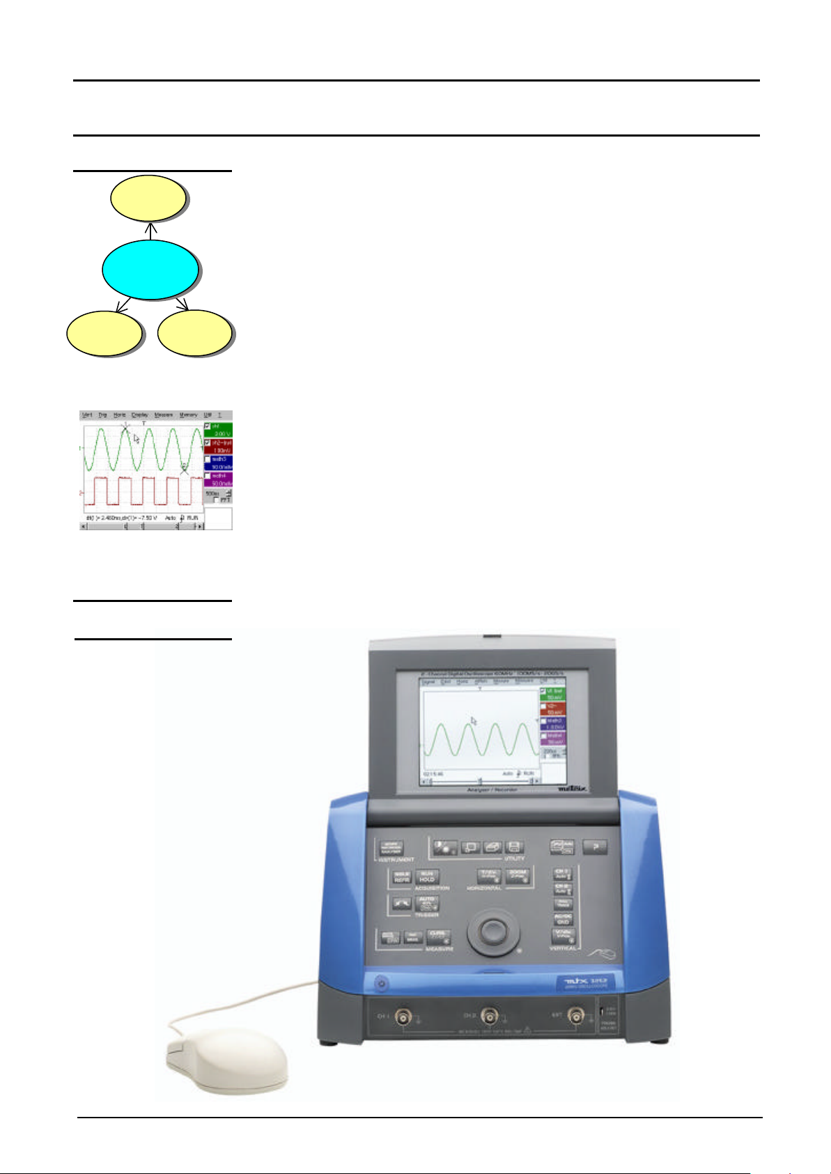
Presentation
This instrument is part of the new MTX range and has the particularity of
Oscilloscope
Recorder
grouping together three units in one:
• a digital oscilloscope incorporating the FFT function, intended to
analyze the signals appearing in the electronics and electrotechnical
fields
• a harmonic analyser mode for breaking down two signals
simultaneously while representing their fundamental and their first 31
harmonics
• a recorder mode (pending) intended for the capture of single or slow
signals.
The instrument works at a constant acquisition depth of 50,000 points.
Memory management is organized from a system of files.
A large-size colour (or monochrome) LCD screen displays the applied signals,
together with all the adjustment parameters.
The main control functions are accessible directly from the front panel.
The adjustment parameters can be modified using the thumbwheel.
A graphic interface is similar to that of the PC and is used for:
• using the mouse to select the functions proposed by the pull-down
menus
• acting directly on objects (traces, cursors, etc.) displayed on the screen.
The adjustment parameters can thus be modified by a variety of means.
This instrument is completed by RS232/CENTRONICS interfaces as standard.
Description of instrument
Overall view
II - 6 Two-channel digital oscilloscope
Page 7
Description of instrument
Description of instrument (cont’d)
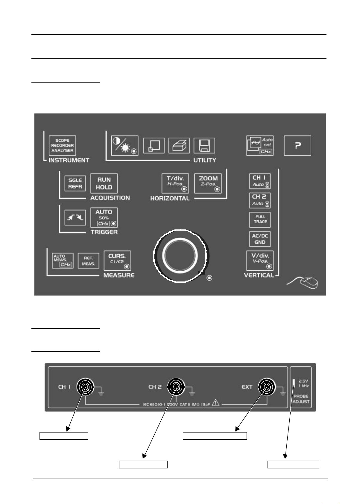
Front panel
(illustration)
Measurement
terminal block
CH1 signal input EXTernal trigger input
CH2 signal input Calibration output
Two-channel digital oscilloscope II - 7
Page 8
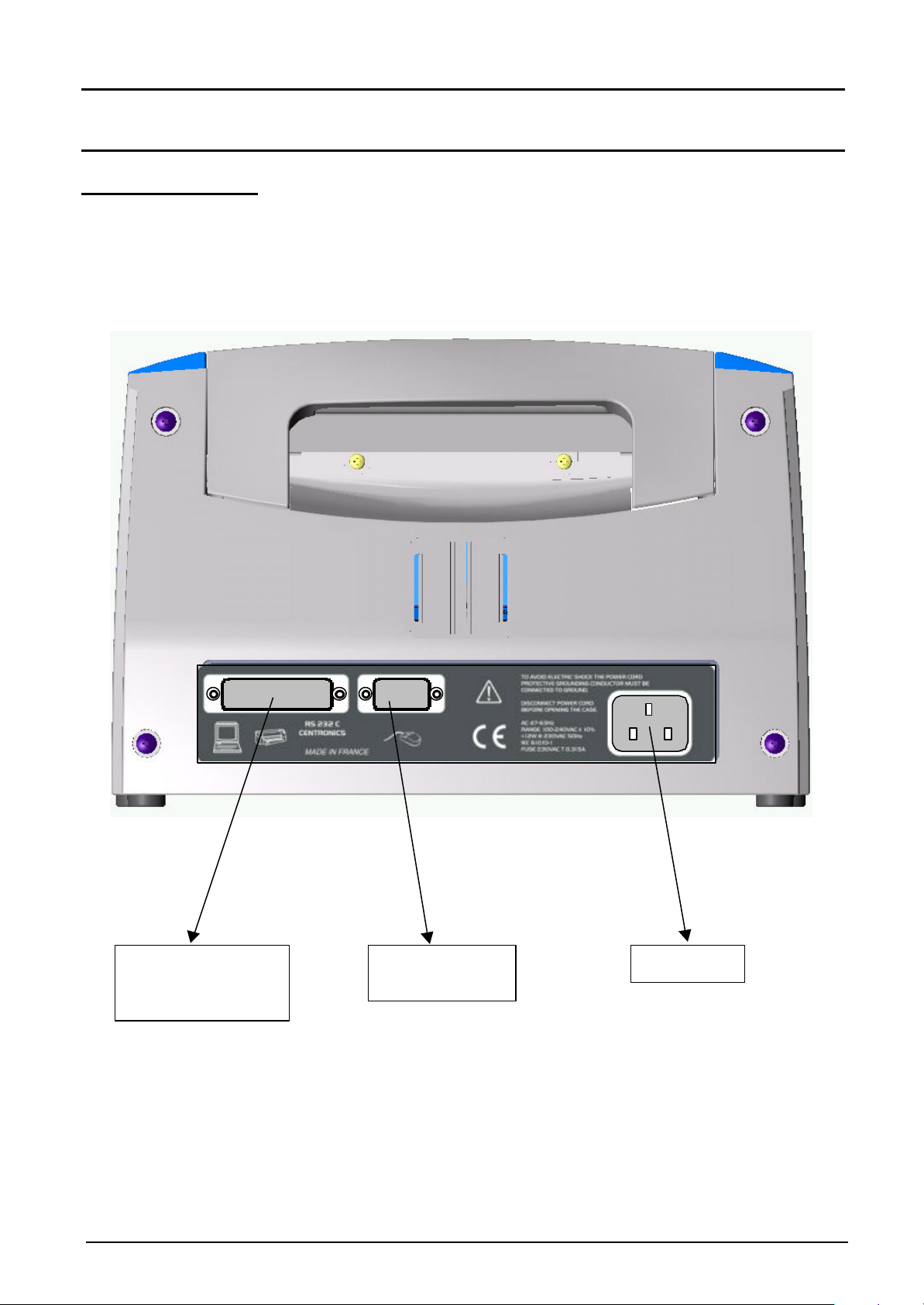
Description of instrument (cont’d)
SUBD 25-pin
SUBD 9-pin
Mains
connector
Rear panel
Description of instrument
female connector for
RS232/CENTRONICS
interfaces
II - 8 Two-channel digital oscilloscope
male connector for
serial mouse
Page 9
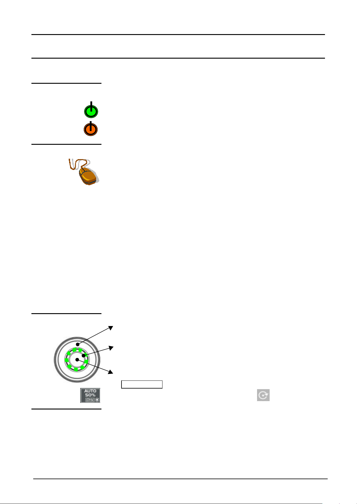
Description of instrument
Description of instrument (cont’d)
Front panel
(description)
1 startup / standby
button
1 mouse / 2 keys
The main features of the equipment can be obtained from the front panel.
They can also be modified directly by the mouse or using the menu toolbar.
activates:
• startup (green LED) when pressed briefly.
• Setting the oscilloscope to standby (red LED) by a long press (> 3 s).
The files and the configuration are saved.
connected to the back of the oscilloscope (SUBD9 connector for serial
mouse), used for: selection of menus,
function validation,
movement of symbols appearing on LCD screen.
• The menus appearing at the top of the screen and the submenus
selected by the mouse pointer open and are validated by the left key.
• The menus in the trace display zone
in the control zone
in the status zone
are opened with the right mouse key.
• The mouse can be used for moving:
symbols appearing in the main display zone:
trigger position, cursor position, display trace reference
symbols appearing in the bargraph:
trigger position, zoomed area cursor position
Position the mouse pointer on the symbol to be moved, holding the left
key of the mouse down during the movement to the desired position.
1 rotary control
button
21 fleeting action
keys
• Zooming in the display zone is possible using the mouse:
hold the left key down when defining the zone with the pointer.
• The outer wheel of this encoder is used for incrementing or
decrementing the selected setting (by rotation).
• The LED comes on when adjustment is possible using the wheel. After
20 seconds without action on the wheel, the LED goes out and the
function is no longer active.
• While the LED is on, pressing the central part of the encoder
(TOGGLE key ) will toggle the adjustment of the main function to the
secondary function of the key. The Symbol : appears on the
keys concerned (except for the key opposite).
giving direct access to the more basic functions.
Two-channel digital oscilloscope II - 9
Page 10
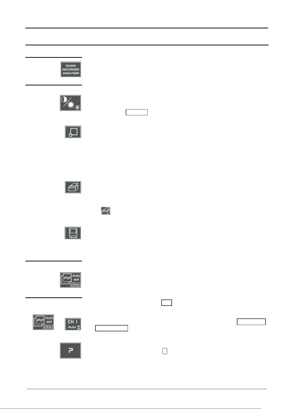
Description of instrument (cont’d)
depressed key (except for the key ??).
Keys
Pressing this key will configure the instrument in the following modes:
« oscilloscope»,
« harmonic analyser » or
« recorder » (pending).
4 «UTILITY» keys
used for access to the LCD contrast adjustment using the thumbwheel.
The LED combined with the thumbwheel comes on à adjustment is accessible.
The thumbwheel TOGGLE key is used for switching the key assignment from
contrast adjustment to LCD brightness.
Pressing causes switchover from normal display mode to "full screen" display
mode (and vice versa).
The screen is organized in such a way as to leave an optimum trace plotting
surface area:
deletion of menu bar,
parameters of traces in time base,
bargraph.
Only permanent adjustments and measurements will remain.
Description of instrument - Keys
G
1 «AUTOSET» key
Selective
«AUTOSET»
with
launches a hardcopy depending on the configuration produced in the « Util »
and « Hardcopy » menus.
A second press before the process end will interrupt current printing.
If printing is impossible, a « Printing error » message will be sent.
The « » symbol is displayed in front of the measurement display zone
when printing is underway.
The first press will freeze the traces on the screen. They will be displayed in
plain language as a reference to be compared with further acquisition.
A second press will erase them: the latter will then be lost.
• Traces will be saved only in the « Memory à Trace à Save » menu.
• The reference memory will be accompanied by a reference Nr.
used on channels to which a signal is applied to obtain optimum automatic
adjustment (General Autoset) of coupling, vertical sensitivity, time base, slope,
framing and trigger.
The lowest frequency signal is used as a triggering source.
If no trace is detected at the inputs, the autoset will be aborted.
Simultaneously pressing with the CHx key (ch1 or ch2) will assign the
corresponding channel as trigger source, initiating an autoset which will take
this selection into consideration.
The CHx channel becomes active for adjustments by means of the AC/DC/GND
and V /div. V-Pos. keys.
1 help key
II - 10 Two-channel digital oscilloscope
activating or deactivating help on the keys.
Whenever a keyboard key is pressed, on-line help will be displayed for the
The functions associated with the keys will not be started up.
On-line help can also be deactivated with the mouse (icon at top right).
The keyboard then resumes normal operation.
Page 11
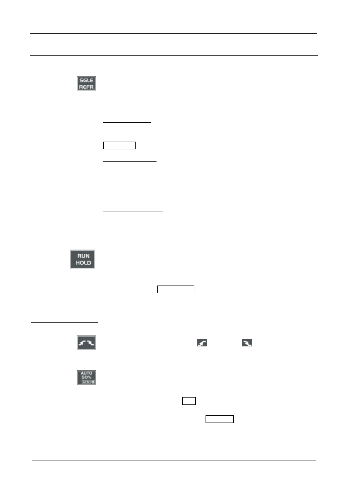
Description of instrument – Keys
Description of instrument (cont’d)
2 «ACQUISITION»
keys
by successive pressing, select one of the following acquisition modes:
Single mode à Single
Trigger mode à Trig’d
Automatic mode à Auto
« SINGLE » mode:
A single acquisition is triggered by pressing the RUN key. HOLD is authorized.
For any further acquisition, the triggering circuit must be reset by pressing the
RUN HOLD key.
«TRIGGER » mode:
The screen content is only refreshed in the presence of a triggering event
related to signals appearing at the oscilloscope (CH 1, CH 2, External or
Mains).
G
G
2 «TRIGGER» keys
If there is no triggering event linked with the signals appearing at the inputs (or
if there is no signal at the inputs), the trace is not refreshed.
«AUTOMATIC » mode:
The screen content is refreshed even if the triggering level is not detected on
the signals appearing at the inputs.
In the presence of a triggering event, screen refreshing is managed as in the
« Triggered » mode.
• allows starting or stopping of acquisition in « TRIGGER » and
« AUTOMATIC » mode.
• resets the triggering circuit in the «Single» mode.
Acquisition is initiated according to the conditions defined by the
acquisition mode (SGLE REFR key).
Acquisition status is indicated in the status zone:
RUN = started READY = wait STOP = stopped
PRETRIG = before trigger POSTRIG = after trigger
selects the trigger slope (positive or negative ) by successive
pressing.
The slope is indicated in the status zone.
sets the trigger level to the average value of the signal (50%) without
modifying the trigger coupling.
The thumbwheel is assigned to adjusting the trigger level.
Combined pressing with the CHx key launches the same function, but
previously sets the corresponding channel as triggering source.
No functions are associated with the TOGGLE key of the thumbwheel.
G
Two-channel digital oscilloscope II - 11
Page 12

Description of instrument (cont’d)
3 « MEASUREMENT »
keys
activates or deactivates the display of the window for the 18 automatic
measurements of the reference trace.
Combined pressing with the CHx key displays the measurements on the
corresponding channel.
When the automatic measurement window is active, the left mouse button
is used for selecting at most 2 measurements that will appear in the status
zone at the bottom of the screen.
used for selecting (successive pressing) among the displayed traces, the
reference trace for the automatic and manual measurements.
Appears in the « Measurement » à Reference menu.
activates or deactivates the cursor displays for manual measurements.
The LED combined with the thumbwheel comes on: the latter allows cursor
1 to be moved horizontally over the screen.
The thumbwheel TOGGLE key is used for moving from the cursor 1 to
cursor 2 horizontal movements and vice versa.
Description of instrument - Keys
2 «HORIZONTAL»
keys
• The dt measurements made (time difference between the two cursors)
and the dv measurement (voltage deviation between the two cursors) are
reported in the status zone.
• The selected cursor position is entered into the active adjustment zone.
used for access to adjustment of time base coefficient (T/div.) by
thumbwheel or for adjustment of horizontal position (H-Pos.) by the
thumbwheel TOGGLE key.
The LED associated with the wheel lights up à the selected adjustment is
possible with this device.
The H-Pos. adjustment modifies the horizontal (time-related) position of the
trigger point.
activates or deactivates the « Zoom » function.
The LED associated with the wheel lights up: the thumbwheel is assigned
to the horizontal zoom coefficient adjustment.
Pressing the thumbwheel TOGGLE key makes it possible to change from
the horizontal zoom coefficient setting to Z-Pos. horizontal movement in the
zoomed zone.
A zone can be zoomed by tracing a rectangle around the zone to be
enlarged using the left mouse button. The sensitivity, time base and
horizontal and vertical alignment values are recalculated automatically.
If no zones to be zoomed are selected with the mouse, a simple horizontal
G
zoom by default will be performed with respect to the screen center.
II - 12 Two-channel digital oscilloscope
Page 13
Description of instrument – Keys
Description of instrument (cont’d)
Definition :
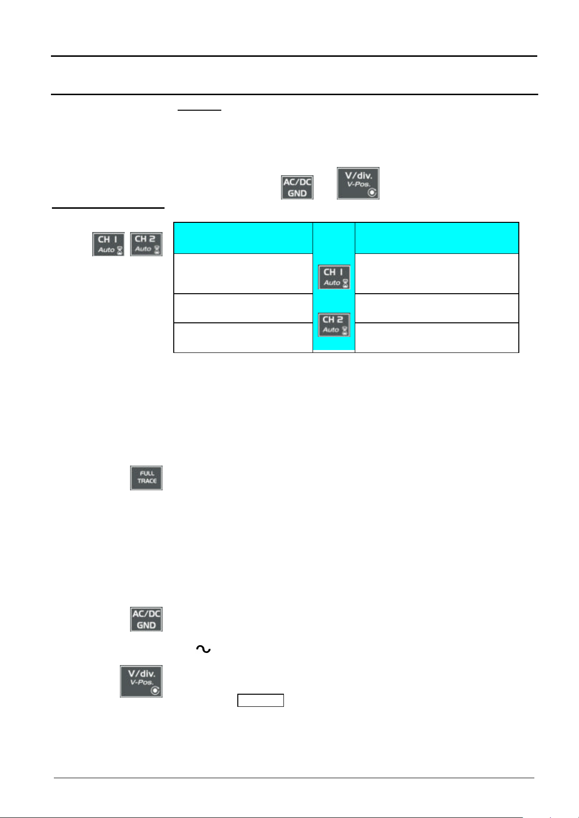
Validated channel = Display enable (trace displayed after RUN)
Displayed channel = Validated channel and trace on screen
Selected channel = Parameter settings enabled for this channel via the
keys:
and .
5 «VERTICAL» keys
Before pressing one of the
following keys:
The channel concerned is not
displayed.
The channel concerned is
displayed, but not selected.
Press
on
or
After pressing one of the
opposite keys:
The channel is displayed and is
selected. The thumbwheel is
assigned to sensitivity adjustment.
The channel is selected.
The channel concerned is
displayed and selected.
The channel is deselected.
Pressing one of these 2 keys for a long time generates a vertical autoset:
• This modifies the sensitivity and vertical positioning of the wheel in
question.
• It optimizes the display on the screen by activating and selecting the
channel.
The channel is displayed and selected. The thumbwheel adjusts the
sensitivity.
activates or deactivates the horizontal division by two, in the display zone.
The activated « Full Trace » function is indicated by:
- the presence of a continuous horizontal line in the middle of the display
zone
- the horizontal division in two of the graticule.
After the activation of the function:
- traces 1 and 3 are assigned to the upper part of the display,
- traces 2 and 4 are assigned to the lower part in order to eliminate their
superimposition.
The traces can then be moved vertically in the two zones.
used for selecting, by successive pressing, input coupling « AC », « DC »
or « GND » for the last channel selected.
Coupling is indicated in the channel parameters zone:
AC : , DC : nothing, ground: GND
Each press will provide access, through the thumbwheel, to the setting of
the sensitivity (V/div.) of the last channel selected.
Pressing the T OGGLE key will move from sensitivity adjustment to vertical
position adjustment (V-Pos.).
The LED associated with the wheel lights up à adjustment is possible with
this device.
Two-channel digital oscilloscope II - 13
Page 14
Oscilloscope Mode
Direct access to
4. Menu bar
1. Status zone
Display and
Contrast
Display
Display
Oscilloscope Mode - Display
73.0%
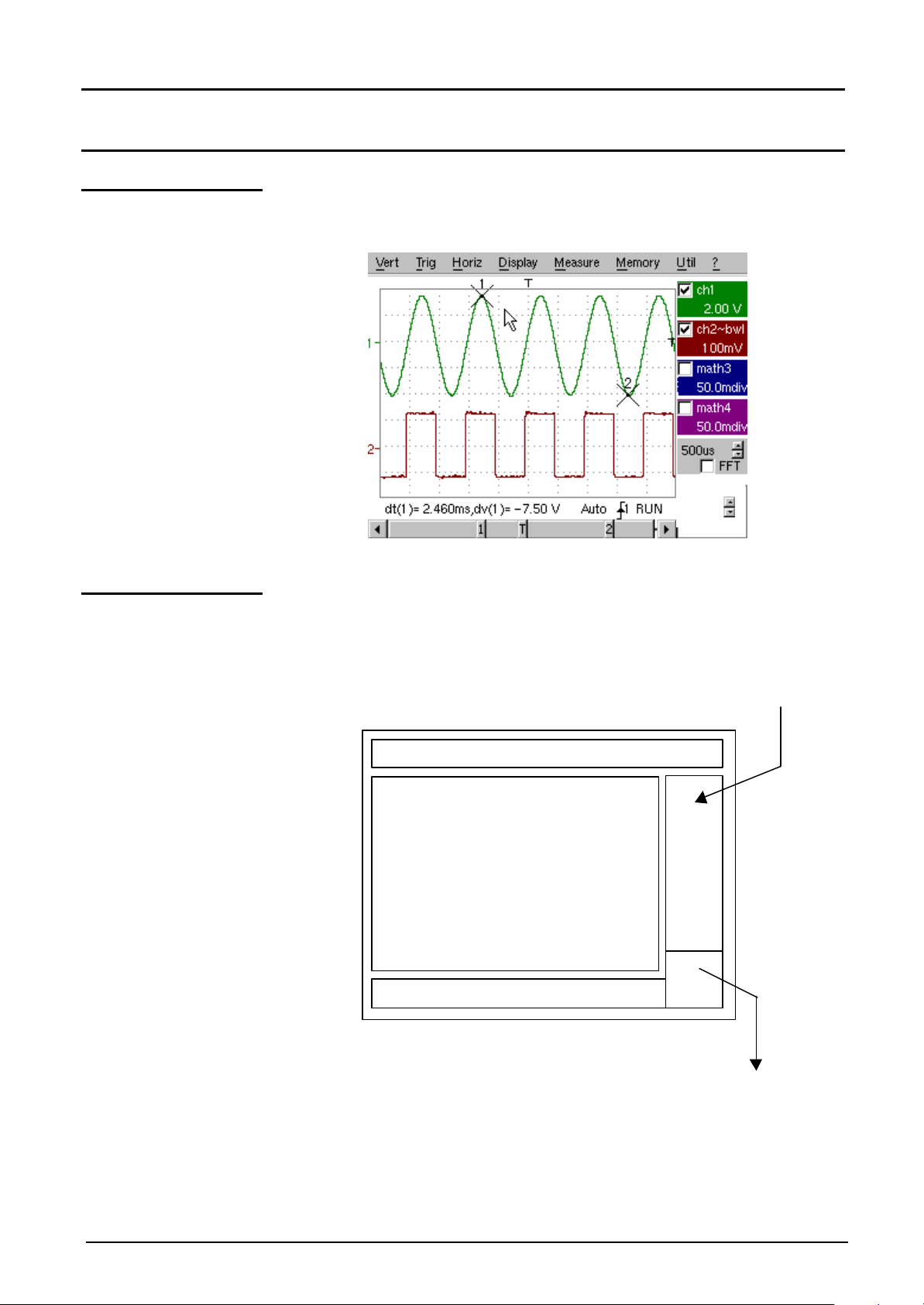
Composition The oscilloscope display is divided into 4 functional zones.
current adjustment
3. Display zone
2. Control
zone
III - 14 Two-channel digital oscilloscope
adjustment of
current value
Page 15

Oscilloscope Mode - Display
33
Position and movement
Position and movement of
manual cursors
Movement of screen to right
Permanent
Representation and
Oscilloscope Mode (cont’d)
1. Status zone
Three types of general information appear in this zone:
• The bargraph represents the screen position, that of the trigger and
• Permanent instrument settings.
• Measurements when the cursors are on the screen (or display of time
Bargraph
Cursor Measurements
Movement to left of screen in
acquisition memory
the cursors in the acquisition memory.
otherwise).
movement of screen in
acquisition memory
T1
of time trigger
adjustments
2
4
in acquisition memory
G
Permanent settings
G
Cursor measurements
Each bargraph element can be moved via the mouse left button.
This zone refers to the triggering status (mode, front, source, current
status).
@ Example : AUTO . 1 STOP
When the cursor of the mouse is placed over this information, the right
mouse button will open the "Trigger parameters" menu.
This zone refers either to:
• horizontal (dt) and vertical (dv) difference between 2 cursors in the
case of manual measurements,
• phase measurement in the case of manual phase measurement (Ph).
(@ Example : dv(1) = 500 µs, dv(1) = 2.00 V)
• automatic measurements selected by the "Automatic measurements"
or "Phase measurement" menu.
• time display, if no measurement has been selected.
Two-channel digital oscilloscope III - 15
Page 16
Oscilloscope Mode (cont’d)
Indication and adjustment of last selected
Display of trace parameters (in trace
Display of function parameters (in trace
Display of ZOOM mode
Value of time base coefficient (s/div) in
Change of signal representation domain
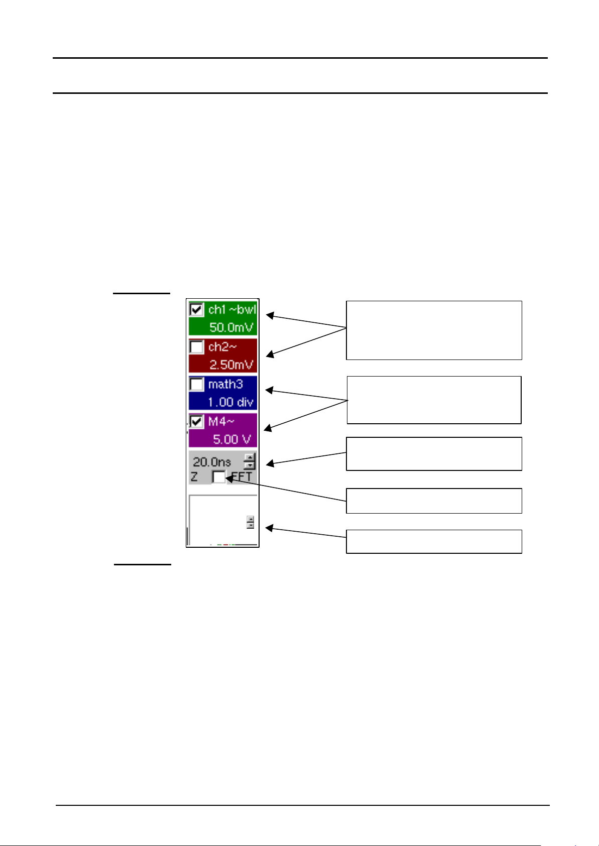
2. Control zone The parameters displayed in this zone are:
• The parameters of each channel and trace: display,
• The time base value and the loading of the signal representation domain
(FFT)
• The active adjustment of the last selected element:
- trigger level
- trigger time position
- channel offset value
- X & Y position of cursor
- …
Oscilloscope Mode - Display
sensitivity, coupling,
bandwidth limit, vertical scale,
function, zoom.
color):
validity, coupling, bandwidth limit,
sensitivity
Display of ZOOM mode
color):
validity, value of division
oscilloscope mode or frequency (Hz/div)
in FFT mode
Contrast
25.0 %
(FFT selection)
adjustment
G • The mouse left key validates the channels and the functions.
• The « PP » symbol indicates whether a channel or function has been
selected, or whether the FFT mode has been selected.
• The adjustments of the time base (or frequency) and the value of the
active parameter can be made with the UP/DOWN button alongside
the current value display using the mouse key button.
• After a change to the time base, the corresponding sampling frequency
is entered into the adjustment zone.
III - 16 Two-channel digital oscilloscope
• When the mouse is placed over the parameters of a channel or time
base value, the right mouse button opens the associated menus
directly.
- Sensitivity/Coupling and Vertical scale, for channels
- Vertical scale for the functions
- Source, trigger mode and RUN/STOP, for the time base
Page 17
Oscilloscope Mode - Display
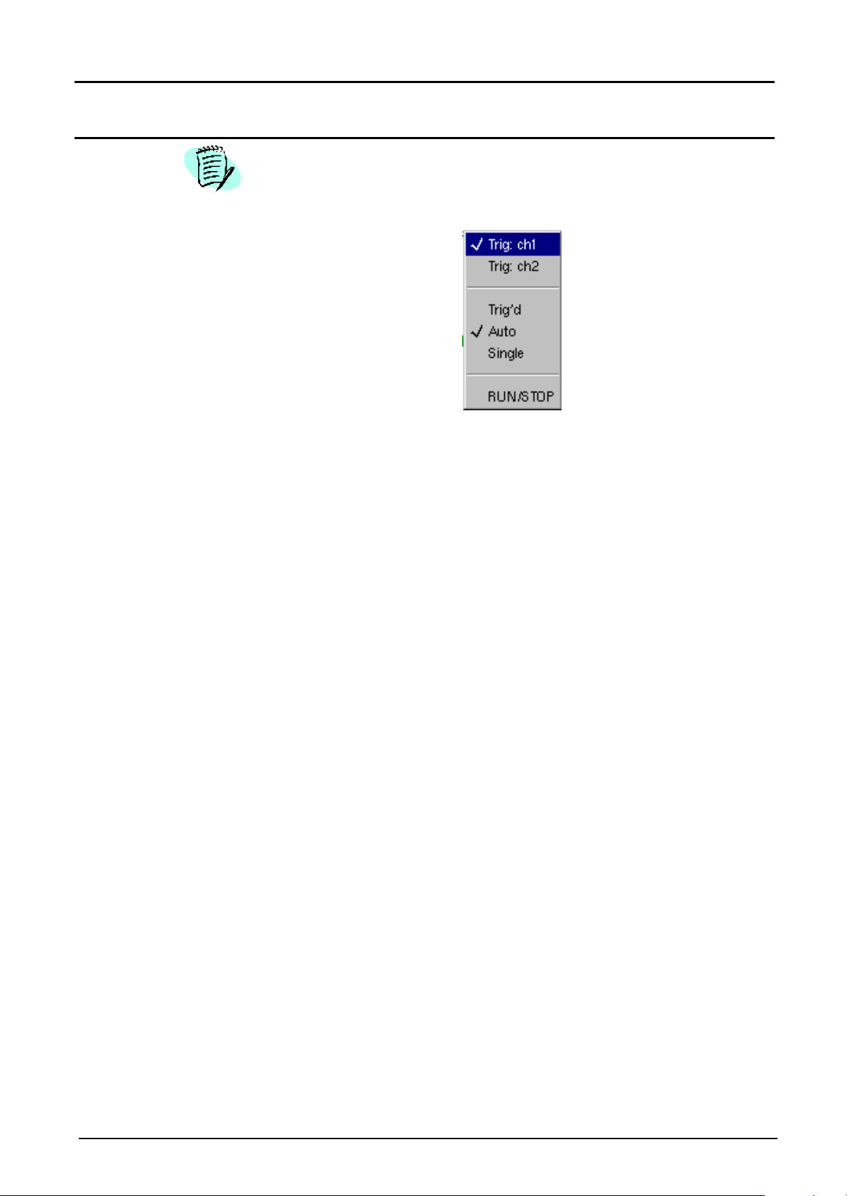
Oscilloscope Mode (cont’d)
The « Sou rce » and « Trigger mode » menus are grouped together and
can be opened using the right mouse button by placing the pointer over
the time base zone.
RUN/STOP is used for starting and stopping acquisition from this menu.
The acquisition status is indicated in the screen status.
G • The symbol « PP » indicates the source and selected trigger mode
3. Display zone
• The trigger source selectable from this menu is limited to the channels
(ch1 or ch2).
The displayed graphic elements associated with the traces in this zone
are:
• a trigger time position indicator
• a trigger level indicator
• a vertical position indicator for the reference level of each trace
• cursor position indicators linked with the curve for automatic
measurements
• cursor position indicators linked or not linked with the curve for manual
measurements
• the selection of a zoom zone
Two-channel digital oscilloscope III - 17
Page 18
Oscilloscope Mode (cont’d)
7
8
1
345
2
1
>
v
266v12
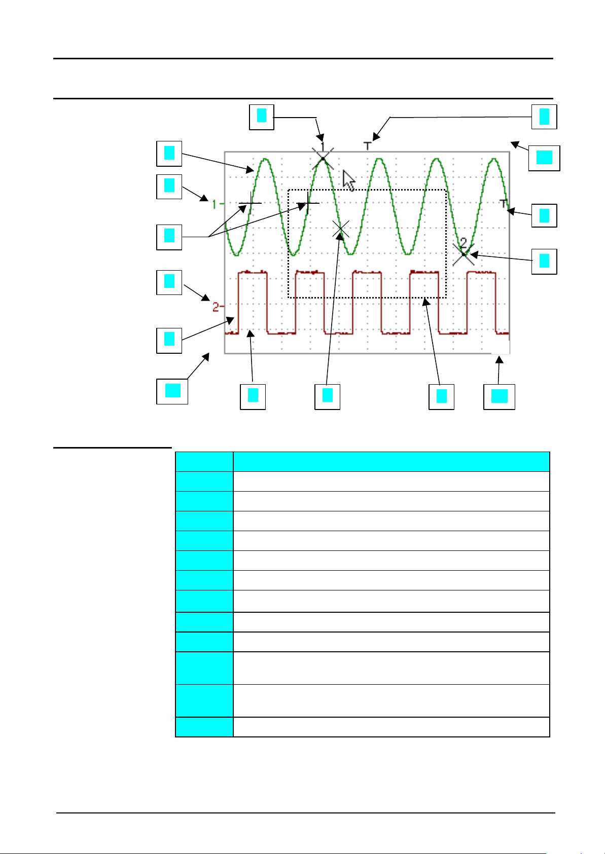
Display elements
Oscilloscope Mode - Display
10
ϕϕ
Definition of
display
9
Items Elements
1 Trace displayed
2 Indication of displayed trace reference level vertical position
Trace affichée
3 Indication of time-related position of trigger
4 Graticule division
5 Automatic measurement cursor position indicator
6 Manual measurement cursor position indicator
7 Phase measurement cursor position indicator
8 Trigger level position indicator
9 Zoom zone selection
10 Time position output indicator of trigger outside displayed
window
11
11 Trigger level position output indicator outside displayed
window.
12 Channel level output indicator outside displayed window
III - 18 Two-channel digital oscilloscope
Page 19
Oscilloscope Mode - Display
Oscilloscope Mode (cont’d)
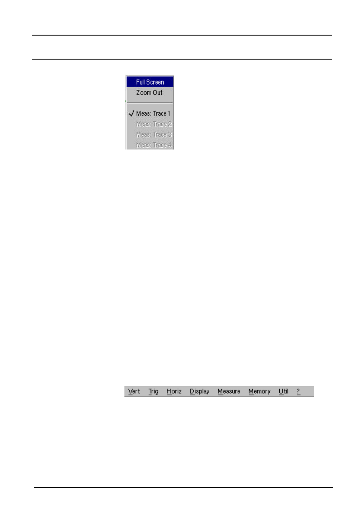
Menu accessible
from display zone
When the mouse pointer is placed in the
display zone, the right key gives direct
access to a display menu.
The « Full Screen » and « Zoom out »
options are directly accessible (see the
Display menu). The same applies to the
selection of the automatic and manual
measurement reference signal (see
Measurement menu).
The «üü » symbol indicates that the
display is in the « Full Screen » mode (if
present) and gives the reference trace for
automatic and manual measurements.
Zooming in the display zone is possible using a mouse, holding the left
mouse key down when the zone is selected by the pointer.
After zooming in to part of the screen, the sensitivities of the traces and
the time base are recalculated.
• The « z » symbol appears in the parameter display of the signals and
the time base.
• The zoomed section is represented in the bargraph.
G
4. Menu bar
• The « Zoom Out » menu (see Display menu) returns to the original
display.
• The horizontal zoom value is adjusted to assign a calibrated value to
the horizontal scale (zoom factor: x200 max.)
• If the zoom vertical selection is greater than 6 divisions, no vertical
zoom will be performed.
All the symbols appearing in the display zone:
- trigger indicators,
- trace position indicator,
- manual cursor position indicator,
- etc …
can be moved using the left button of the mouse.
The new modified symbol value is entered into the current adjustment
display zone.
All the oscilloscope functions can be accessed by the main menus.
Two-channel digital oscilloscope III - 19
Page 20
Oscilloscope Mode (cont’d)
(∗)
See §. Description, page 44.
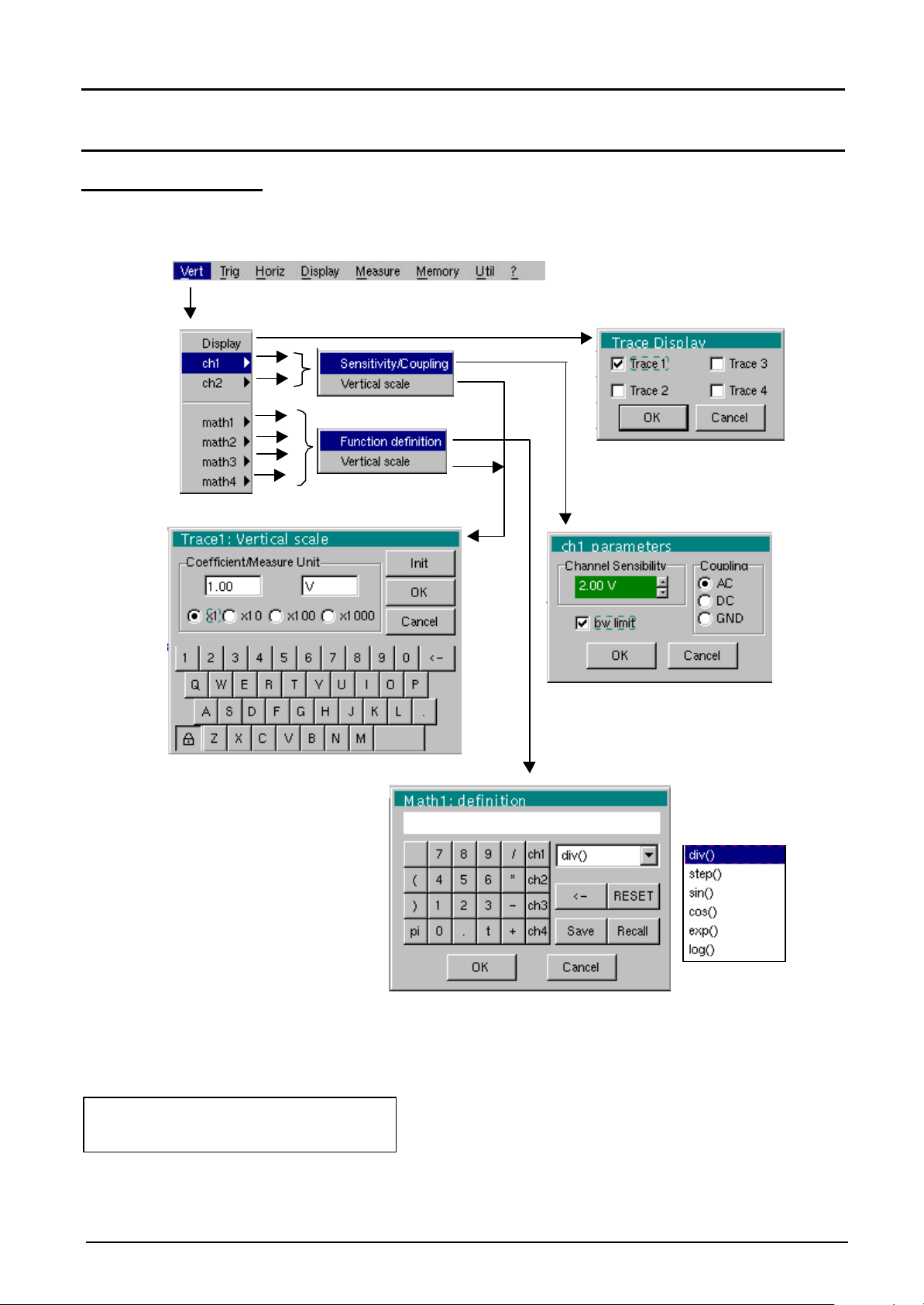
The « Vert » Menu
(∗)
(∗)
(∗)
(∗)
Oscilloscope Mode - The « Vertical » menu
Only available in advanced mode
III - 20 Two-channel digital oscilloscope
ch1-ch2
Page 21
Oscilloscope Mode - The « Vertical » menu
Modifies the sensitivity of the channel using the scroll bar and the left mouse
Oscilloscope Mode (cont’d)
Definition
Display
ch1
ch2
Sensitivity/Coupling
Channel Sensitivity
Coupling
opens the « Trace display » menu for validating or devalidating the traces.
Validation of selections by « OK ». Exit from menu without modification
by « Cancel ».
The « PP » symbol in front of a trace indicates its validation.
G
The traces can be validated or devalidated from the command zone using
the left mouse button.
modifies independently the ch1 and ch2 parameters and modifies the
selected trace vertical scale.
modifies the selected channel parameters.
button, adjustable by sequence: from 2.5 mV to 100 V/div.
G
Sensitivity is entered into the channel parameter display zone. It takes the
« Vertical scale » menu parameters into consideration.
Modification of the AC - DC - GND coupling
GND Coupling: the equipment connects internally the selected
channel input to a 0 V reference level.
The « ¤ » symbol indicates the selected coupling. Coupling is reported in
G
the modified channel parameter display zone.
BW limit
Vertical scale
Coefficient assigns a multiplication coefficient to the selected channel sensitivity.
limits to 20 MHz the bandwidth of the channel and its trigger circuit to
moderate the display noise and the false triggers.
G
The « PP » symbol indicates that the bandwidth limit is active and « bwl »
appears in the modified channel parameters.
Validation of selections by « OK ». Exit from menu without modification
by « Cancel ».
This menu can also be called by clicking with the right mouse key in the
desired channel parameter display zone.
defines the vertical scale of the channel selected from the current
adjustments. Reading and direct measurements of the analyzed
magnitude and its unit are obtained.
The modification is made using the mouse with the table of usable
numbers, having selected the « Coefficient » zone.
The ß key deletes the previous value of the cursor in this zone.
The predefined values (x1, x10, x100, x1000) correspond to standard
probe coefficients and can be assigned directly.
The sensitivity value indicated in the channel parameter display will be
G
modified according to this coefficient.
Two-channel digital oscilloscope III - 21
Page 22

Oscilloscope Mode (cont’d)
Measure unit modifies the vertical scale unit of the selected channel.
The modification is carried out by the mouse using the table of characters
that can be used after selecting the measure unit zone.
The ß key is used for deleting the character leading the cursor in this
zone.
The vertical scale unit will be entered into the modified channel parameter
G
display.
Init re-initializes the multiplication coefficient at 1.00 and returns to a measure
unit in Volt.
Validation of selections by « OK ». Exit from menu without modification
by « Cancel ».
This menu can be called by dialogue with the right mouse button in the
display of the desired channel parameters (ch1 or ch2).
Oscilloscope Mode - The « Vertical » menu
math1
math2
math3
math4
Function definition
@ Examples
defines for each trace a mathematical function and the vertical scale.
Menus present only in Advanced mode (see menu « Util »).
defines the mathematical function to be assigned to the selected trace.
The function is defined using the usable characters table, and associating
the ch1 and ch2 traces.
Predefined mathematical functions can be associated with the traces:
step (« step ») using the « t » (∗)
sin (« sine ») cos (« cosine »)
exp (« exponential ») log (« logarithmic »)
(∗) t = sample abscissa: varies from 0 to 50,000 points (screen).
math1 à ch1 ∗ step (t - 10000) : math1 is at 0 V while t < 10,000 points.
math1 = ch1 when t > 10,000 points.
math1 à ch1 + div(1): for adding a division to the ch1 trace.
math1 à ch1 ∗ step (10,000 - t) : math1 = ch1 while t < 10,000 points.
math1 is at 0 V when t > 10,000 points.
math1 à sin (pi ∗ t / 20,000) ∗ exp (- t / 10 000) ∗ div(4) : absorbed sine
div (« division »)
equation
mathx cannot be used in the definition of a function. The drafted functions
G
can be backed up and called up later by the icons « Save » and « Recall »
(see §. Memory).
III - 22 Two-channel digital oscilloscope
Page 23

Oscilloscope Mode - The « Vertical » menu
Oscilloscope Mode (cont’d)
Save
Recall
ß
Reset
G
Vertical scale defines the vertical scale of the selected trace.
Opening menu from
math3, math4
Coefficient modifies the value of a selected trace division (div).
backs up the definition of the function by the “File Copy “ menu. Extension
«.FCT».
calls up the definition of a function recorded as a file «.FCT».
deletes the character preceding the cursor in the window.
completely resets the function definition.
Validation of selections by « OK ». Exit from menu without modification
using « Cancel ».
After assigning a function to the ch1 (math1) or ch2 (math2) channels,
« mathx » appears in the corresponding channel parameter display zone.
G
Calling this menu from math1, math2 is identical to calling ch1, ch2.
Modification is by using the mouse with the table of numbers that can be
used after selecting the coefficient zone.
The ß key deletes the character preceding the cursor in this zone.
G
Measure unit
G The vertical scale unit will be entered into the modified trace parameter
Init
Predefined values (x1, x10, x100, x1000) correspond to standard probe
coefficients and can be assigned directly.
The value of a division will be entered into the display of the modified trace
parameters.
modifies the unit of the vertical scale (div) of the selected trace.
Modification is performed by means of the mouse with the table of
characters that can be used after selecting the management unit zone.
The ß key deletes the value preceding the cursor in this zone.
display (3 characters max).
re-initializes the coefficient at 1,000 and returns to a unit of measure in div.
Validation of selections by « OK ». Exit from menu without modification
by « Cancel ».
The « Vertical scale » menu can also be called up by clicking with the right
mouse key in the trace parameter display math3 or math4 as desired.
Two-channel digital oscilloscope III - 23
Page 24

Oscilloscope Mode (cont’d)
The « TRIG » Menu
Oscilloscope Mode - The « Trigger » Menu
Definition
Parameters
used for selecting the « trigger parameters »:
Source used for selecting one of the 4 sources as trigger signal.
CH 1 Synchronization by channel CH 1
CH 2 Synchronization by channel CH 2
External Synchronization by external source connected to the front
panel BNC EXT plug
Mains Synchronization by power supply signal (mains)
The trigger source is indicated at the bottom of the screen in the status
zone (1: Channel CH1 ; 2 : Channel CH2 ; E : External; S : Mains).
Synchronization by channel CH1 or CH2 may also be called by clicking
with the right mouse key in the time base display zone.
Coupling used for selecting one of the trigger source filters:
AC AC coupling (10 Hz to 100 MHz) : blocks the continuous
signal component
DC DC coupling (0 to 100 MHz): allows the entire signal through
LF Reject Reject of source signal frequencies < 10 kHz (facilitating
observation of signals having a DC component)
HF Reject Reject of source signal frequencies > 10 kHz (facilitating
observation of signals having high frequency noise)
TV-frame Triggering synchronization pulse for TV frame
TV-line Triggering of TV line pulse. Recommended scan coefficient
for examining a TV line: 0.5 µs to 20 µs/div.
III - 24 Two-channel digital oscilloscope
Page 25

Oscilloscope Mode - The « Trigger » Menu
Oscilloscope Mode (cont’d)
Edge/polarity used for selecting trigger edge:
+ ascending trigger edge
- descending trigger edge
G The selected trigger edge is entered into the status zone.
Trigger level
Noise reject By default, the trigger circuits operate with hysteresis of ½ division. This
used for modifying with mouse by adjusting trigger level on the scroll bar
(Trigger).
The trigger level is entered into the current value display zone after
G
modification. It can be adjusted accurately.
option brings hysteresis to 1 division.
G The « üü » symbol indicates that the noise rejection mode is active.
The « ¤ » symbol indica tes the selected parameters.
Validation of selections by « OK ». Exit from menu without modification
by « Cancel ».
This « Trigger parameters» menu can also be called up by clicking with
the right mouse key in the trigger adjustment display.
Trigger mode The 3 following selections define the trigger mode:
Triggered mode
Automatic mode
used for acquisition and refreshing the screen on each trigger event.
used for acquisition and automatic refreshing of screen even when there is
no trigger event. Visible traces, even when there is no trigger event.
Single mode
Two-channel digital oscilloscope III - 25
used for acquiring signal and refreshing the screen on the first trigger
occurring after a trigger reset by pressing the key opposite (or by the time
base menu).
• The « PP » symbol indicates the selected trigger mode.
G
• The selected trigger mode is entered into the status zone (Trigger,
Auto, Single).
• The acquisition state is indicated in the status zone: STOP, RUN,
PRETRIG, POSTRIG, READY….
This selection can also be called up by clicking in the time base display
zone with the right mouse key.
Page 26

Oscilloscope Mode (cont’d)
The « Horiz » Menu
(∗)
Oscilloscope Mode - The « Horizontal » Menu
(∗) Only available in advanced mode.
See §. Description, page 44.
Definition
min/max Acquisition
Averaging
allows the signal to be sampled at high frequency (50 MS/s), even for
slow time base speeds. The display does not take extreme value
samples into consideration.
This mode is used for:
• detecting wrong representation due to under-sampling
• displaying short-term events (Glitch, ≥ 20 ns).
Whatever time base is being used, the short-term events (Glitch ,
≥ 20 ns) will be displayed.
The « PP » symbol indicates the « min/max Acquisition » mode is active.
G
This menu is used for selecting a coefficient to calculate an average for
the displayed samples. For instance, this is a way of attenuating
random noise observed in a signal.
No averaging
Average rate 2
Average rate 4
Average rate 16
Average rate 64
III - 26 Two-channel digital oscilloscope
The averaging coefficient are: no averaging
averaging by 2, 4, 16, 64.
Page 27

Oscilloscope Mode - The « Horizontal » Menu
Oscilloscope Mode (cont’d)
The calculation is made using the following formula:
FFT
(Fast Fourier
Transform)
Pixel N = Sample *1/Average rate + Pixel
with: SampleValue of new sample acquired at abscissa t
Pixel N Ordinate of pixel of abscissa t on screen, at moment N
Pixel N-1 Ordinate of pixel of abscissa t on screen, at moment N-1
The « PP » symbol indicates the selected average rate.
G
(1-1/Average rate)
N-1
This menu is used for selecting calculation of the Fast Fourier
Transformer in « real time » (FFT).
The Fast Fourier Transform (FFT) is used for calculating the discrete
representation of a signal in a frequency domain from its discrete
representation in the time-related domain.
The FFT can be used in the following applications:
• measurement of various harmonics and distortion of signal,
• analysis of pulse type response,
• search for noise source in logic circuits.
The FFT is calculated at 2500 points.
G
The Fast Fourier Transform is selected by the FFT icon in the command
zone.
When the curve is zoomed, the FFT applies to the zoom part of the
curve.
Description The Fast Fourier Transform is calculated according to the equation:
N
1
−
2
X (k) =
1 2
N
x n j
* ( )*exp −
∑
N
n
=−
2
nk
π
for k ∈ [0 (N – 1) ]
N
with: x (n): a sample in the time-related field
X (k): a sample in the frequency-related field
N: resolution of FFT
n: time-related index
k: frequency-related index
The displayed trace represents the amplitude in V or dB of the various
signal frequency components depending on the selected scale.
The signal continuous component is deleted by software.
Two-channel digital oscilloscope III - 27
Page 28

Oscilloscope Mode (cont’d)
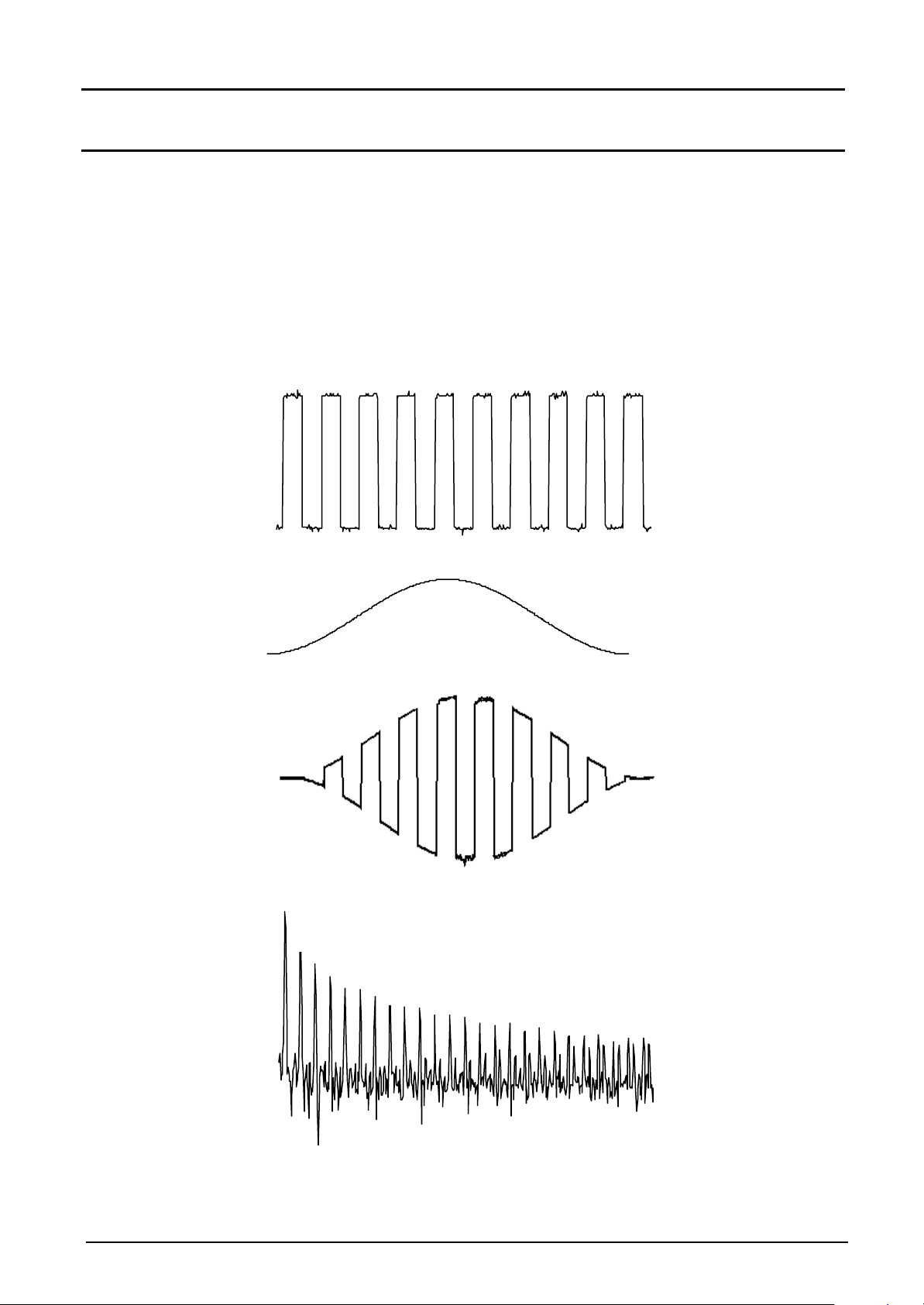
Square signal on ch2 of 10 kHz and 5
FFT with a rectangular window and a
FFT with Hanning window and
Oscilloscope Mode - The « Horizontal » Menu
Vpp
logarithmic scale
∗ ∗ FFT units
Horizontal unit: indicated instead of time base; calculated according to the
scan factor:
Unit (in Hz/div.) =
Vertical unit: two possibilities are offered by sub-menus:
a) Linear scale: by selecting the FFT menu, then the linear scale
• in V/div.=
b) Logarithmic scale: by selecting the FFT menu, then log scale
(logarithmic)
• in dB/div.: by attributing 0 dB to a signal having 1 effective amplitude
division in time-related representation.
The vertical position indicator of the representation is at -40 dB.
G
12,5
scan factor
signal unit in time-related representation (V/div.)
2
linear scale
∗ Graphic representation
The FFT representation indicates symmetry compared to the frequency
origin; only positive frequencies are displayed.
III - 28 Two-channel digital oscilloscope
• The « PP » symbol, appearing before one of the options indicates the
G
selected scale.
• Manual measurements (dt, dv) can be made using cursors for a
frequency representation (see §. Menu « Measurement »).
• The choice of scale appears directly on selection of the FFT menu.
Page 29
Oscilloscope Mode - The « Horizontal » Menu
Oscilloscope Mode (cont’d)
The sub-menus are used for selecting a type of window.
Rectangular
Hamming
Hanning
Blackman
Before calculating the FFT, the oscilloscope weights the signal to be
analyzed by a window acting as a bandwidth filter. The choice of window
type is essential to distinguish between the various beams of the signal
and to make accurate measurements.
Time-related
representation of
signal to be analyzed
Weighting window
Weighted signal
Frequency
representation of
signal calculated by
FFT
Two-channel digital oscilloscope III - 29
Page 30

Oscilloscope Mode (cont’d)
The final duration of the design interval results in a convolution in the
signal frequency domain with a function sinex/x.
This convolution modifies the graphic representation of the FFT because
of the side lobes characteristic of the sinex/x function (unless the interval
of design contains an integer of periods).
Four types of window selections are available: the menus appear directly
on selection of the FFT menu.
Oscilloscope Mode - The « Horizontal » Menu
Window type Main lobe
width
Rectangular window - 13 dB
Hanning window - 32 dB
Hamming window - 43 dB
Blackman window - 94 dB
Max. amplitude of side
lobe (compared to main
lobe)
4 π /N
8 π /N
8 π /N
12 π /N
Effects of under-sampling in frequency representation:
If the sampling frequency is not correctly adjusted (less than or twice the
maximum frequency of the signal to be measured), the high frequency
components will be under-sampled and appear in the graphic
representation of the FFT by a state of symmetry (reployment).
• The « Autoset » function is activated. It is a way of avoiding the above
phenomenon and adjusting the horizontal scale: the representation is
more legible.
• The « Zoom » function is active.
G
The « PP » symbol appears in front of one of the options, indicating the
selected function.
III - 30 Two-channel digital oscilloscope
Page 31

Oscilloscope Mode – The « Display » Menu
Oscilloscope Mode (cont’d)
The « DISPLAY »
Menu
(∗)
Definition
Graticule
Display modes
Envelope
Zoom off
(∗) Only available in advanced mode.
See §. Description, page 44.
Used for displaying grid or not.
There are two available display modes:
Vector
A vector is traced at the centre of the sample.
The minimum and maximum observed on each horizontal position of the
screen are displayed. This mode is used to display drifting in time or
modulation.
The “PP ” symbol indicates that the display mode is active.
G
Initiates return to the original screen size, after zooming in on part of the
screen.
G
• This function is inactive unless the screen is in zoom mode.
• The letter Z in the trace parameter and time base zone denotes the
zoom mode.
This menu can also be called up by clicking with the mouse right key
inside the trace display zone.
Two-channel digital oscilloscope III - 31
Page 32

Mode Oscilloscope (cont’d)
Oscilloscope Mode - The « Display » Menu
Full screen
Oscilloscope
XY
causes changeover from the normal display mode to the “full screen”
display mode and vice versa.
The display is organized so as to leave the biggest surface area possible
for trace plotting: only the permanent settings and the automatic or
manual measurements remain
G
• This function has the same effect as the key.
• The “PP ” symbol indicates that the full screen mode is active.
This function can also be called up by clicking with the mouse right button
in the trace display zone.
The following submenus make it possible to change from oscilloscope to
XY mode.
G
The “PP” symbol indicates the active mode.
This is the basic operating mode.
The “XY source” menu is used for assigning the desired traces to the X
axes (horizontal) and Y axes (vertical).
G
@ Example
Validation of selections by “OK”. Exit from menu without modification
by “Cancel”.
• Each axis is graduated into 8 divisions.
• The selected traces are identified by a figure corresponding to their
axis.
• The “••” symbol indicates the trace selected for each axis.
Two sinusoidal signals assigned to the X and Y axis with an offset of π/2
are then represented by a circle.
III - 32 Two-channel digital oscilloscope
Page 33

Oscilloscope Mode - The « Measurement » menu
(∗)
Oscilloscope Mode (cont’d)
The « Measure » Menu
(∗)
Definition
Reference
Automatic
measurements
Trace 1
Trace 2
Trace 3
Trace 4
G
Only available in advanced mode.
See §. Description, page 44.
used for selecting one of the active traces on which you want to make
automatic or manual measurements.
Only the active traces can be selected. Inactive traces appear lighter.
The « PP » symbol indicates the reference trace.
used for opening the « automatic measurements » menu.
The measurements are made and refreshed on the selected reference
trace. All the measurements that can be made on this trace are
displayed.
(- . - -) is displayed for the measurements that cannot be made.
The window can be closed and validated by clicking on OK with the
mouse left button.
The one or two selected measurements will be displayed in the status
zone.
Two-channel digital oscilloscope III - 33
Page 34

Oscilloscope Mode (cont’d)
difference
G • It is possible to select two permanent measurements.
• The « PP » symbol indicates the measurement(s) that will be entered
into the status zone.
• Activating automatic measurements reveals two cursors (+) on the
curve at the beginning and end of the period, if at least one period is
visible on the screen.
• The display order corresponds to the chronological order of the
selection.
Deleting automatic measurements in the status zone is carried out using
this menu, by erasing the selected measurements (no « PP » symbol in
the automatic measurements table).
Oscilloscope Mode - The « Measurement » Menu
Reference memory
@ Example
G
18 automatic
measurements
Vmin
Vmax
Vpp
Vlow
Vhigh
Vamp
Vrms
Vavg
Over+
trise
tfall
W+
W-
P
DC
Pulses
Over-
The activation of the "Reference memory difference" option is a way of
calculating the deviations for all the automatic measurements between
the selected trace and the memorized reference trace (see §. Memory
Menu).
Calculation made and displayed on one of the 18 measurements:
Vpp (Reference memory difference ) = Vpp (Trace 1) – Vpp (Trace 1 à Ref 1)
For all the measurements, calculation is made in the same way.
• This option is only active if a reference trace is present. It has to
correspond to the trace on which automatic measurements are to be
made (@ E.g.: Trace 1 and Trace 1 à Ref. 1).
• Condition: the reference trace must have the same characteristics as
the associated trace (sensitivity and time base).
minimum peak voltage
maximum peak voltage
peak-to-peak voltage
established low voltage
established high voltage
amplitude
rms. voltage
mean voltage
positive overflow
rise time
fall time
positive pulsewidth (at 50 % of Vamp)
negative pulsewidth (at 50 % of Vamp)
period
F
frequency
cyclic ratio
number of pulses
negative overflow
III - 34 Two-channel digital oscilloscope
Page 35

Oscilloscope Mode - The « Measurement » menu
L
Oscilloscope Mode (cont'd)
Measurement
conditions
Automatic
measurement
presentation
• The measurements are made on the displayed part of the trace.
• Any change to the signal will lead to an updating of the measurements.
They are refreshed in step with acquisition.
• If several signal periods are displayed on the screen, the measurement
will refer to the first.
• To make automatic measurements on specific portions of the signal,
enclose the desired measurement zone with manual cursors and
markers identifying the zone.
• Measurement precision is optimum, if two complete signal periods are
displayed
T = 1/F
W+ W-
Vmax
Vhigh
Vamp Vpp
100%
90%
50%
Vavg
L
>5%T
10%
0%
Tfall
t0t1t2 t3t4t5
• Positive overflow = [100 * (Vmax – Vhigh)] / Vamp
• Negative overflow = [100 * (Vmin – Vlow)] / Vamp
i n
=
1
• Vrms =
• Vpp =
Y
= value of representing zero Volt
GND
[ (y y ) ]
∑
n
i n
=
1
∑
n
i 0
=
−
i
i 0
=
(y y )
−
i
2 1/ 2
GND
GND
Vlow
Vmin
>5%TTrise
t6
Two-channel digital oscilloscope III - 35
Page 36

Oscilloscope Mode (cont'd)
•
•
Oscilloscope Mode - The « Measurement » Menu
Phase measurement
Trace1 Phase
Trace2 Phase
Trace3 Phase
Trace4 Phase
G
Manual
measurements
(dt, dv)
used for making trace phase measurements with respect to a reference
trace (See §. Reference Measurement).
This menu selects the trace on which phase measurements are to be made.
To deactivate phase measurements, de-select it using the same menu for
the selected phase measurement.
• The « PP» symbol indicates the selected trace for phase measurement.
The activation of the phase measurement, if possible, will reveal 3 cursors:
2 automatic measurement cursors on the reference trace,
1 cursor indicating ϕ on the trace, on which the phase measurements
are made.
These 3 cursors are fixed; they cannot be moved.
• The phase measurement (in °) of the selected trace with respect to the
reference trace is indicated in he measurement display status zone
(@ E.g.: Ph (1/2) = 180°).
• If the measurement cannot be made, « - . - - » appears.
used for making measurements by cursor.
The measurement cursors (1 and 2) are displayed as soon as the menu is
activated.
The two measurements made are:
dt (time deviation between the two cursors)
dv (voltage deviation between the two cursors).
The measurements made and the displayed cursors are linked with the
selected reference trace (see §. Reference Measurement).
• The « PP» symbol indicates that the manual measurements (dt, dv) are
G
active.
• The measurement cursors can be moved directly with the left mouse
button. They can also be moved using the mouse by selecting the symbol
1 (cursor 1) or the symbol 2 (cursor 2) in the bargraph.
• If the free cursor option is not active (see §. Measurement « Unattached
cursors »), the cursors will remain linked to the reference trace during
movements. If this option is active, the cursors can be moved anywhere
on the screen.
• dt and dv measurements with respect to the selected reference are
indicated in the measurement display status zone.
@ E.g.: dt(1) = 500 µs, dv(1) = 1.00 V
Manual phase
measurement
III - 36 Two-channel digital oscilloscope
used for making phase measurements with 3 cursors: 2 identified cursors
« 1 and 2 » identical to those of the manual measurements and a 3rd free
cursor with respect to which the phase measurement is made (see
"Unattached cursors" menu for the movement of cursors "1 and 2").
G
The « PP» symbol indicates that the manual phase measurement is active.
• When this menu is active, the 3 cursors are present if at least one signal is
active.
• The cursor identified
cursors" menu is not active.
ϕ
can be moved freely even if the "Unattached
• The phase measurement (in °) between these cursors is indicated in the
measurement display status zone. @ E.g.: Ph = 120.0 °
Page 37

Oscilloscope Mode - The « Measurement » menu
Oscilloscope Mode (cont'd)
Unattached cursors
Particular case
used for linking or not linking the manual measurement cursors (1 and 2)
to the reference trace.
When the "Unattached cursors" menu is selected, cursors 1 and 2 can
be moved freely over the screen.
• The « PP» symbol indicates that the "Unattached cursors" menu is
G
active.
• To deactivate this menu, de-select it with the mouse.
• For automatic measurements and automatic phase measurements, the
cursors are fixed: they cannot be moved. The "Unattached cursors"
menu will be inactive.
In the case of "Automatic measurements" and manual measurement
activation:
If the manual cursors and automatic markers are displayed together, the
automatic measurements will be made on the portion of the trace defined
by the manual cursors.
If the portion defined by the manual cursors is too restricted to make the
selected automatic measurements [in this case, the fixed markers (+) are
not displayed], the selected automatic measurements will be impossible
and « -.-- » will appear in the measurement display zone.
De-select the automatic measurements to validate the manual
G
measurements (dt, dv).
Two-channel digital oscilloscope III - 37
Page 38

Oscilloscope Mode (cont'd)
trace
The « MEMORY »
Menu
Oscilloscope Mode - The « Memory » Menu
Definition
Trace1 àà Ref. 1
Trace2 àà Ref. 2
Trace3 àà Ref. 3
Trace4 àà Ref. 4
used for storing the selected trace in its volatile reference memory
(@ E.g.: Trace 1 in Ref. 1).
The 4 traces have their reference memory.
G • For optimum use: the reference trace must have the same characteristics
as the associated trace (sensitivity and time base).
• A trace can only be saved to the reference memory if it is present on the
screen.
• The memorized traces appear in plain language, together with their
reference number.
• The « PP» symbol in the menu indicates that the corresponding trace has
been saved to the reference memory and must be present on the screen.
• A reference trace cannot be moved.
• A reference memory can be deactivated by de-selecting it from the menu.
III - 38 Two-channel digital oscilloscope
Page 39

Oscilloscope Mode - The « Memory » Menu
Save.TXT
∗
Oscilloscope Mode (cont'd)
Trace This menu is used for saving (to the non-volatile memory) or recalling the
trace of a reference memory. Saving can be in two formats: « .TRC » or
« .TXT ».
The « File copy » menu is suited to the type of selected format.
Save .TRC
G
Saving of the files for recalling on the oscilloscope screen
The saving files will take the extension .TRC; they can be recalled in the
« Trace à Recall » menu.
saving of files for export to another application
Saving files take the extension .TXT; they cannot be recalled by the « Trace
à Recall » menu for screen display. However, they can be exported in a
standard format use in another software (spreadsheet).
(@ E.g.: Microsoft EXCEL) using the menu « Util à Files ».
The selection made opens a « File Copy » menu.
∗ Then in the "Source" pull-down menu, select the trace or the reference
memory which is to be recorded.
The trace or the reference memory to be saved will appear in gray. The
selection will be made using the left mouse key.
• Only the traces and reference memories on the screen will be entered into
the "Source" menu and therefore be selectable.
• If all the traces and all the reference memories are present on the screen,
the scrollbar to the right of the menu will allow movement through the list.
∗ A default backup file name is proposed above the keyboard. It can be
modified using the "Qwerty" keyboard and the mouse.
The ß key is used for deleting the displayed letter preceding the cursor in
this zone.
Once the name has been written, the à key records it by entering it into the
destination menu and closes the menu. The backup file takes the extension
.TRC (internal format) or .TXT (text format), in accordance with the previous
selection.
Exit from the menu without backup is obtained by clicking with the left mouse
key on the icon at the top right of the window.
G • The file name is limited to a maximum of 8 characters + the extension.
• As soon as the mouse pointer id dragged over a destination file (without
clicking), the name is accompanied by its recording date and time, and its
size.
• If the name already exists or is not compatible, an error message will
appear.
Two-channel digital oscilloscope III - 39
Page 40

Oscilloscope Mode (cont'd)
•
Oscilloscope Mode - The « Memory » Menu
Recall.TRC
Configuration used for saving or recalling an equipment configuration.
Save when selected, opens the « File copy » menu.
when selected, opens a « File Copy » menu.
In the pull-down Source menu is the .TRC file list recorded using the « Trace
à Recall.TRC » menu.
The file name selected for recalling appears in gray. Selection is made using
the left key of the mouse.
∗ After selecting the file to be recalled, the destination menu indicates the trace
on which it should be restored. The selected destination trace (1 to 4), using
the mouse left key to restore the signal, appears in gray. It is also indicated
in the lower zone of the screen.
∗ The trace to be recalled and its destination are selected, then the à key is
used for performing the operation and closing the menu.
Exit from the menu without using this recall feature is obtained by clicking the
mouse left key on the icon at the top right.
G
• If the selected destination trace is already present on the screen, it will be
pushed out by the recalled trace.
When a trace is recalled, Mx appears in the destination trace parameters.
• In this menu, the « Qwerty » keyboard is ineffective.
∗ In the Source menu is a file called « Configuration ». It contains the
equipment configuration parameters when this menu is opened.
∗ A save file name is proposed above the « Qwerty » keyboard. It is used
for modifying it (left mouse key).
The ß key deletes the displayed letter preceding the cursor in this zone.
∗ When the source file name has been entered, the à key is used for
recording the configuration by transferring it into the destination menu and
closing the menu (save file: extension .CFG).
Exit from the menu without saving is obtained by clicking the icon at the top
right of the window, with the left mouse key.
G
• The file name is limited to a maximum of 8 characters + its extension. As
soon as the mouse pointer passes over a source file (without a click) it is
accompanied by its recording date, recording time and size.
• If the name already exists or is incompatible, an error message will appear.
Recall
when selected, opens the « File copy » menu.
∗ In this pull-down "Source" menu is a list of files (.CFG) recorded using the
"Configuration « Configuration à Save » menu.
The file name, selected for recalling, appears in gray. Selection is by the
left mouse key. The scrollbar on the right is used for moving through the
list.
∗ With the source file selected, the à key is used for recalling the item.
∗ Exit from the menu without recalling is obtained by clicking with the left
mouse key at the top right of the window.
G • In this menu, the « Qwerty » keyboard is ineffective.
• The default config file is used for restoring the works configuration.
III - 40 Two-channel digital oscilloscope
Page 41

Oscilloscope Mode - The « Utilities » Menu
SINUS.TRC 01/12/02 8.49
Oscilloscope Mode (cont'd)
The « UTIL » Menu
CONFIG.CFG 01/12/02 8.55
FONC.FCT 01/12/02 9.00
Two-channel digital oscilloscope III - 41
1
6
01/Dec./02
01/Dec./03
Page 42

Oscilloscope Mode (cont'd)
Definition
Oscilloscope Mode - The « Utilities » Menu
File
when selected, open the « File manager » menu.
It contains all the files
• recorded since the beginning of equipment use
• created since the last startup. These files will definitely been saved
when switching off (see key shown opposite).
Caution : If a power cut occurs when configuration saving, the files
contained in the file manager will be lost.
The (.CFG) configuration save files
(.TRC) trace save files
(.FCT) function save files
(.PCL, .EPS, .BMP, .GIF, .PRN) print save files
are accompanied by their date and time of recording and their size.
The selected file appears in gray. The left mouse key selects the file and
the scrollbar on the right is used for moving through the list.
File typeGselects the desired file type by the scrollbar:
. CFG .TRC .FCT .PRN .PCL .EPS .BMP .GIF
Selection uses the mouse left key.
« *.* » used for selecting all the file types.
The storage capacity of the file manager is 1 Mbytes.
I/O port config.
Stop bits selects the number of stop bits (1 or 2 stop bits).
Protocol
Open leads to the restoration of the selected file by the “File Copy”
menu
Erase deletes the selected file
Export transmits the file over the active communication interface
(RS232/CENTRONICS)
Exit from this menu is by clicking with the mouse left key on the icon at
the top right of the window.
when selected, opens the « RS232 » menu.
This menu is used for configuring the remote programming interface.
This interface uses the SUBD 25-pin female connector located on the
back of the unit.
Speed selects the transmission speed : from 300 to 115200 Bauds.
Format selects the word length: 7 or 8 bits.
Parity selects the type of parity: even, odd or no parity (none).
selects the serial link management mode.
Hard Hardware: the protocol is by the RTS and CTS lines of the
RS232 link.
Soft Software: use of the Xon and Xoff characters to time the
transmission and reception of messages (reduced "3-wire"
link).
None No protocol check.
• The « ••» symbol indicates the selected option.
G
• An option can be modified using the left mouse key.
III - 42 Two-channel digital oscilloscope
Page 43

Oscilloscope Mode - The « Utilities » Menu
Oscilloscope Mode (cont'd)
Hardcopy
Option
Port
G
when selected, opens the « Hardcopy » menu.
This menu is used for selecting the print format or the printer type, as well as
the communication port that will be used for making hardcopies.
The printer type or selected format will appear in gray. Selection uses the left
mouse key. The scrollbar on the right is used for moving through the list of
types or the printer languages.
used for choosing color or black/white printing.
used for selecting the interface to be used for print data transfer: RS232C,
CENTRONICS or to file.
• If the RS232C interface is selected for making a hardcopy, the
parameters used (speed, format, parity, stop bit, protocol) will be
configured in the "I/O Port Config" menu. Check that the configuration is
suited to that of the peripheral connected to the instrument.
• The "File" option is a way of recording the hardcopy in a file. Pressing
the key shown opposite opens the "File copy" menu (see “Trace menu à
Save”).
After entering the file name, the à key starts the print job.
Reconfigure then the "Hardcopy" menu according to the type of
connected printer. The transfer of this file to a printer will use the Util à
File menu and the "Export" option.
• The « PP» symbol indicates the selected option.
• An option can be modified using the mouse left key.
Selection validation by « OK ». Exit from menu without modification by
«Cancel ».
Configuration when selected, opens the « Configuration » menu.
This menu is used for configuring the equipment.
Date/time
Language selects the language in which the menus are written.
Screen saver
updates the date (day, month, year) and the time (hour, minute, second).
Selection is by the left mouse key using the scrollbars located either side of
the parameters to be set.
G
The clock starts when the menu is closed.
5 options are possible: French,
English,
German,
Italian,
Spanish.
used for setting the screen to standby after a defined period of time to
minimize the consumption of the equipment and screen aging.
4 options are possible: 15 min,
30 min,
1 h,
no standby mode.
G
The screen is reactivated by pressing any unused key on the front panel.
Two-channel digital oscilloscope III - 43
Page 44

Oscilloscope Mode - The « Utilities » Menu
Oscilloscope Mode (cont'd)
Standby used for setting the equipment to standby after a defined period of use
so as to limit the consumption of the unit.
In this case, the equipment configuration is saved before cutoff.
4 options are possible: 30 min,
1 h,
4 h,
12 h.
The equipment is reactivated using the key shown opposite or using a
front panel key not taken into consideration.
G • The « •• » symbol indicates the selected option.
• The option can be modified using the left mouse key.
Selection validation by « OK ». Exit from menu without modification by
« Cancel ».
System used for sending the user information about the life of the equipment
starting from commissioning.
Startup sequences
Use duration
Last calibration date indicates the date of the last equipment calibration.
Next calibration date
« Advanced »
Mode
indicates the number of equipment starts.
indicates the total utilization time in hours.
indicates the date of the next equipment calibration. Period equipment
calibration is necessary to guarantee all the announced specifications.
For any checks of the equipment, see §. Maintenance, Metrological
G
checking.
Exit from this menu is by clicking on the icon at the top right with the left
mouse key.
When activated, the« Advanced » mode gives access to all the
equipment functions.
Conversely, when this mode is not active, the advanced equipment
functions no longer appear in the menus.
Menus present in « Advanced » mode only:
- math1, math2, math3, math4 à accessible through the « Vert » menu
- averaging à accessible through the « Horiz » menu
- XY à accessible through the « Display » menu
- Unattached cursors à accessible through the « Measurement » menu
G
• The « üü » symbol indicates that the "Advanced" mode is active.
• Modification uses the mouse left key.
• By default, the "Advanced" mode is not active.
• In the "Non-Advanced" mode, the equipment configuration is not
saved on stoppage, using the key shown opposite.
III - 44 Two-channel digital oscilloscope
Page 45

Oscilloscope Mode - The « Help » Menu
MTX3352-C, V1.01/A01
Oscilloscope Mode (cont'd)
The « ? » Menu
Definition
Help
About
when selected, opens the « Help » menu.
This menu is used for activating on-line help using the equipment keys,
in the same way as the key shown opposite.
The ß and à keys are used for scrolling through the description of the
keys on the front panel.
The key name is used above the explanation.
Exit from the menu is obtained by clicking with the left mouse key on the
icon at the top right of the window.
when selected, opens an information file.
This file refers to the equipment software version and gives its date of
creation.
Exit from the menu is by OK .
Two-channel digital oscilloscope III - 45
Page 46
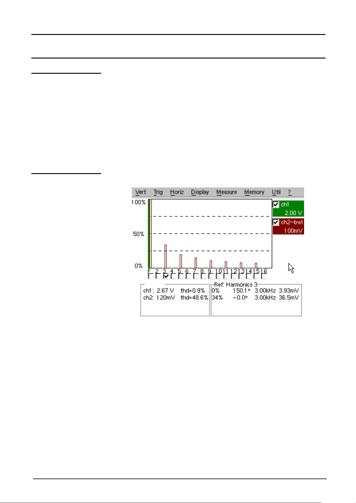
« Harmonics » Mode
Display
« Harmonics » Mode - Display
Presentation
Display
Harmonic analysis displays the fundamental and the 31 harmonics
In this mode, the time base is adaptative, and is not manually adjustable.
This analysis is reserved for signals whose fundamental frequency is
included between 40 Hz and 5 kHz.
All the conventional adjustments of the oscilloscope (except for the time
base) remain active in this mode (Sensitivity/Coupling, Vertical scale).
Only the channels (and not the functions) can be the subject of harmonic
analysis.
The harmonic analyses of the two signals can be displayed
simultaneously.
Signal
IV - 46 Two-channel digital oscilloscope
Page 47
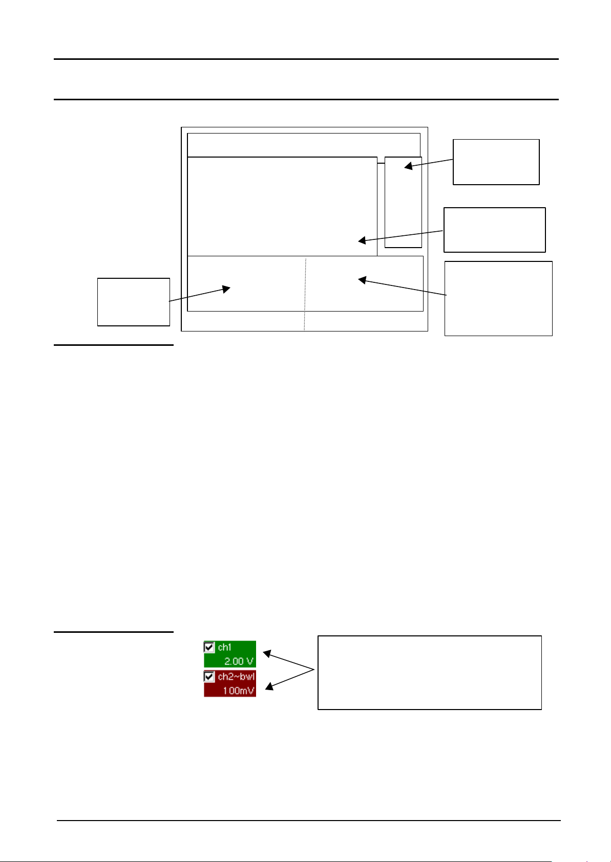
« Harmonics » Mode - Display
Direct access
adjustments
area
Trace
Display of
Selection of
harmonic
Display:
« Harmonics » Mode (cont’d)
Composition Harmonic mode display is divided into 4 functional zones:
4. Menu base
1. Display zone
to current
information
display
1. Display zone
2. Control
fundamental or
3. Status zone
information about
selected
fundamental or
harmonic
displays the result of harmonic analysis of a single trace (ch1 or ch2) or
the 2 traces simultaneously (ch1 and ch2).
Harmonic analysis of the ch1 trace is shown in a darker display, and that
of the ch2 trace in lighter display (or same color as the trace).
The display appears as a bar chart, whose vertical axis is graduated as
a percentage of the fundamental amplitude (from 0% to 100% every
25%).
The horizontal axis represents the harmonics, i.e.:
• the fundamental (F) and the first 16 harmonics
• the even harmonics from 2 to 30
• the odd harmonics (from 3 to 31) and the fundamental (F)
This breakdown of the harmonics is used for selecting, with the mouse
left key, the fundamental (F) or one of the harmonics, (@ E.g.: Ref.
Harmonic 5) for making automatic measurements of the selected
element.
• The « PP» symbol indicates the selected harmonic.
G
• See the "Display" menu for the selection of the harmonics.
2. Control zone
• of trace parameters in trace color:
validity, coupling, bandwidth limit,
sensitivity
• of Zoom mode
• When the mouse is dragged over the parameters of a channel, the
G
right button is used for directly opening the associated menus
« Sensitivity/Coupling » and « Vertical scale ».
• The left key of the mouse is used for channel validation.
• The « PP» symbol indicates whether the channel is selected.
Two-channel digital oscilloscope IV - 47
Page 48

« Harmonics » Mode (cont’d)
« Fundamental Ref. »
Information display about
traces
Information display about
harmonic
« Harmonics » Mode - Display
3. Status zone
The « SIGNAL » zone
The status zone returns the automatic measurements made on the
signals and the selected harmonic.
Signal
fundamental or selected
indicates:
- the active channel(s): ch1 and/or ch2 (- - -) when the channel is not
active
- the root mean square (RMS) of the signal in V
The
or « Harmonic » zone
4. Menu toolbar
- the harmonic distortion factor (THD) in %
indicates, for the fundamental or the selected harmonic, (@ E.g.: Ref.
Harmonic 3) :
- its value as a % of fundamental
- its phase in ° with respect to the fundamental
- its frequency in Hz
- its rms. voltage in V
The same menu toolbar is used as in "Oscilloscope" mode; some menus
are adapted to the "Harmonic Analysis" mode and the others are not
active.
IV - 48 Two-channel digital oscilloscope
Page 49

Harmonics Mode - The « Vertical » Menu
Harmonics Mode (cont'd)
The « Vert » Menu
Definition
Display
G
Two-channel digital oscilloscope IV - 49
when selected, opens the "Trace display" menu used for validating or
invalidating the traces.
Validation of selections by « OK ». Exit from menu without modification
by « Cancel ».
• The « PP» symbol in front of a trace indicates its validation.
• Harmonic analysis of the ch1 signal is represented in a darker display,
and that of ch2 in a lighter display (or trace colour).
• In the "Harmonics" mode, only the channels (and not the functions) are
the subject of harmonic analysis.
• Traces 3 or 4 cannot be selected.
Page 50

Harmonics Mode (cont'd)
Harmonics Mode - The « Vertical » Menu
ch1
ch2
Sensitivity/Coupling modifies the parameters of the selected channel.
Channel Sensitivity
Coupling
Bandwidth limitGBandwidth limit of the channel and its trigger circuit at 20 MHz, to
used for modifying independently the ch1 and ch2 channels parameters
and modifying the selected trace vertical scale.
modifies sensitivity of channel by scrollbar with left mouse key:
from 2.5 mV to 100 V/div.
The sensitivity is given in the channel parameter display zone. It takes into
G
consideration the parameters of the "Vertical scale" menu.
Modification of AC - DC - GND coupling
GND coupling: equipment connects the selected channel input to the
0 V reference level.
G
The « ¤ » symbol indicates the selected coupling.
It is entered into the modified channel parameter display zone.
moderate the display noise and false triggering.
The « PP » symbol indicates that the "Bandwidth limit" mode is active and
"bwl" appears in the modified channel parameters.
Validation of selections by « OK ». Exit from menu without modification
by « Cancel ».
This menu can also be called by clicking with the right mouse key in the
selected channel parameter display zone (ch1 or ch2).
Vertical scale defines the vertical scale of the selected channel from the current settings.
Coefficient Assignment of a multiplication factor to the selected channel sensitivity.
Modification is by the mouse using the table of usable numbers after
selecting the "Coefficient" zone.
The ß key is used for deleting the value preceding the cursor in this zone.
Predefined values (x1, x10, x100, x1000), corresponding to standard
probe coefficients and can be assigned directly.
G The sensitivity value indicated in the channel parameter display will be
modified according to this coefficient.
Measure Unit
Modification of the selected channel vertical scale unit.
This modification is made using the mouse and the table of usable
characters, after selecting the "Measure Unit" zone.
The ß key is used for deleting the value preceding the cursor in this zone.
The vertical scale unit will be entered into the modified channel parameter
G
display.
VI - 50 Two-channel digital oscilloscope
Page 51

Harmonics Mode - The « Vertical » Menu
Harmonics Mode (cont'd)
Init re-initializes the multiplication coefficient at 1.0 and returning a measure
unit in Volts.
Validation of selections by « OK ». Exit fr om menu without modification
by « Cancel ».
This menu can also be opened by clicking with the right mouse key in the
selected channel parameter display (ch1 or ch2).
Two-channel digital oscilloscope IV - 51
Page 52

Harmonics Mode (cont'd)
The « HORIZ » Menu
Definition
Harmonics Mode - The « Horizontal » menu
No averaging
Average rate: 2
Average rate: 4
Average rate: 16
Average rate: 64
These menus are used for selecting an average rate to calculate an
average according to the coefficient selected on the displayed
samples.
This selected coefficient attenuates any random noise observed in a
signal.
The selectable average rates are:
no averaging,
average rate: 2,
average rate: 4,
average rate: 16,
average rate: 64.
Calculation is to the following formula:
Pixel N = Sample * 1/Average rate + Pixel N-1 (1-1/ Average rate)
with:
• Sample: value of new sample acquired at abscissa t
• Pixel N : ordinate of abscissa pixel t on screen at
instant N
• Pixel N-1 : ordinate of abscissa pixel t on screen at
instant N-1
The « PP» symbol indicates the selected average rate.
G
IV - 52 Two-channel digital oscilloscope
Page 53

Harmonics Mode - The « Display » Menu - The « Memory » Menu
Harmonics Mode (cont'd)
The « DISPLAY »
Menu
Definition These menus are used for displaying the harmonic composition of the
selected one or 2 signals in 3 groups.
Fund ààHarmonic 16
Even harmonics
Odd harmonics
The
« MEMORY » Menu
displays fundamental and first 15 harmonics.
displays even harmonics from 2 to 30.
displays fundamental and odd harmonics from 3 to 31.
The chosen selection appears under the composition display.
G
• The « PP» symbol under fundamental F or one of the 31 harmonics
indicates the one selected.
• The selection is preserved during a change of display.
See description in "Oscilloscope" mode.
In the "Harmonics" mode, this menu is limited to saving and recalling the
instrument configuration.
Two-channel digital oscilloscope IV - 53
Page 54

Harmonics Mode (cont'd)
The « Util » Menu
See description in « Oscilloscope » mode.
The « ? » Menu
See description in « Oscilloscope » mode.
Harmonics Mode - The "Utilities" Menu - The "Help" Menu
IV - 54 Two-channel digital oscilloscope
Page 55
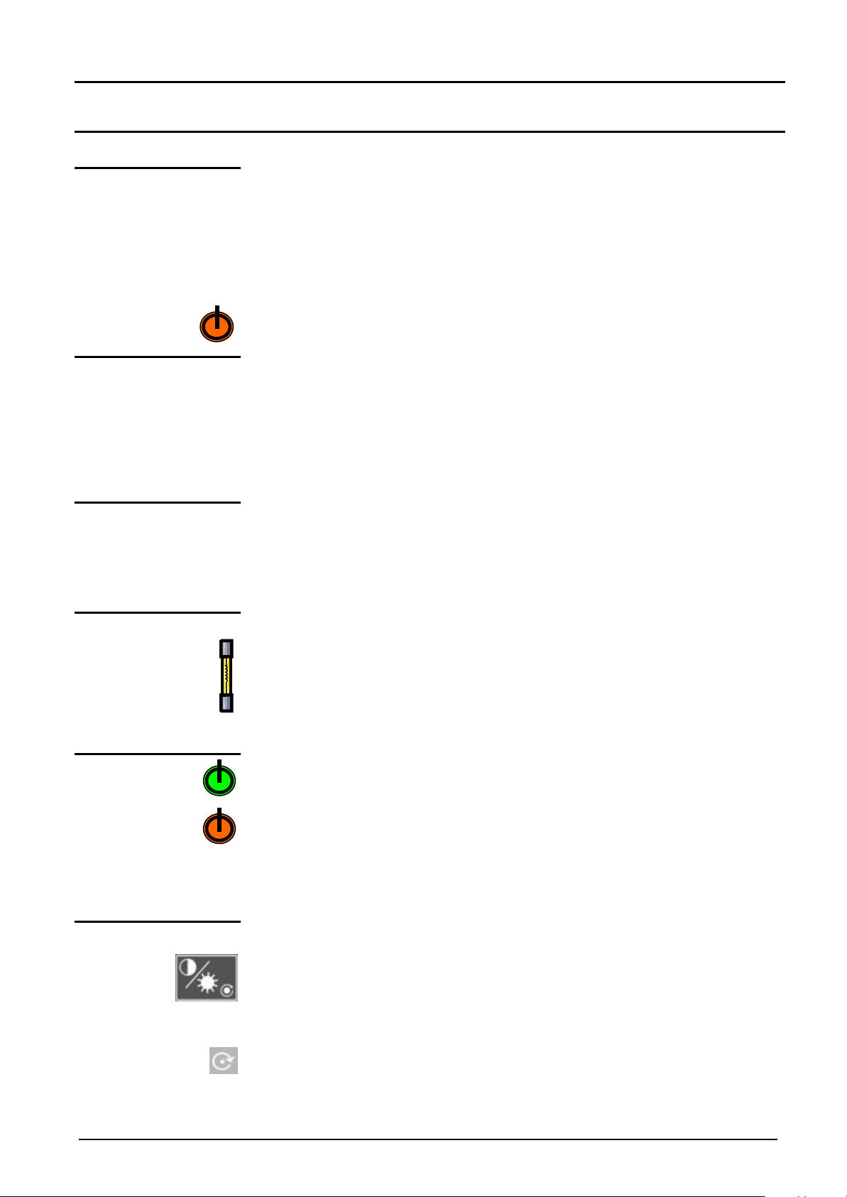
Functional Description
If one of those codes (or the addition of
Functional Description
Preparation for use
Instructions before
startup
Before initial startup:
• Connect the mouse to the 9-pin SUBD connector at the back of the
unit.
• Check the power supply cord which will be connected to the back of
the unit and to the network connector with a ground link is in good
condition.
• When on, the LED shown opposite verifies that the mains voltage is
applied to the oscilloscope.
Error messages
AUTOSET_MICRO 0001
AUTOSET_FLASH 0002
AUTOSET_RAM 0004
AUTOSET_FPGA 0008
AUTOSET_SSRAM 0010
AUTOSET_SCALING1 0020
AUTOSET_SCALING2 0040
AUTOSET_SCALING3 0080
several codes) is present when getting
started à a default has been detected.
In this case, contact your closest
distributor
(See §. Maintenance).
Mains voltage The oscilloscope power supply is designed for:
• a network capable of varying from 90 VAC to 264 VAC (use nominal
range 100 VAC and 240 VAC)
• a frequency included between 47 Hz and 63 Hz.
Startup
LCD contrast
LCD brightness
Fuse The unit is protected by a fuse:
• Fuse rating: T, 2,5 A, 250 V, 5 x 20 mm
This protection fuse must only be replaced by an identical model.
Replacement may only be performed by qualified personnel .
Contact your closest distributor.
The pushbutton starts up the oscilloscope (the LED becomes green after
loading).
A long press (> 3 seconds) switches the equipment to standby (the LED
becomes red).
When the unit is powered up, the last memorized configuration is restored.
G
At initial startup, the default configuration parameters are applied.
This key is used for adjusting the LCD contrast. Adjustment is by the
thumbwheel as long as the LED associated with is on.
The « TOGGLE » key on the thumbwheel is used for switching from LCD
contrast adjustment to brightness adjustment (and vice versa).
Two-channel digital oscilloscope V - 55
Page 56
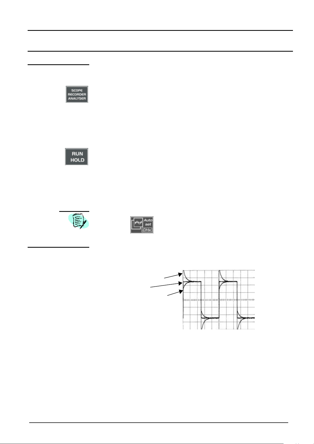
Functional Description (cont'd)
∗
Applications
Functional Description
Calibration signal
display
• Connect the calibrator output (2.5 V, 1 kHz) of the connection zone to the
CH1 input using the 1: 10 ratio measurement probe (for instance).
• Using the key shown opposite, select the « Oscilloscope » mode.
∗ Confirm the signal: Vert Menu à Display: Trace 1
Adjust the ch1 sensitivity: Vert Menu à ch1à Sensitivity/Coupling:
50 mV/div. (1:10 probe)
∗ Adjust the coupling: Vert Menu à ch1à Sensitivity/Coupling: AC
∗ Adjust the sweep speed (time base window): 0,2 ms/div.
∗ Adjust the trigger source: Trig. Menu à Parameter à Source: ch1
∗ Adjust the trigger mode: Trig. Menu à Automatic mode: automatic
∗ Using the key shown opposite, start acquisitions (RUN mode)
If necessary:
∗ Modify the trigger level by the left mouse key by dragging the symbol
T (Trigger) over the screen. The trigger level value is displayed at the
bottom right of the screen.
∗ Modify the vertical framing of the curve by moving the symbol 1 on the
left of the screen using the left mouse key.
The Autoset button is used for automatically checking these
adjustments.
Probe compensation Adjust the audio frequency compensation of the probe so that the signal
plateau is horizontal (see figure below).
Over-compensated probe
Compensated probe
Under-compensated probe
G
Refer to the manual attached to the probe when making compensation.
V - 56 Two-channel digital oscilloscope
Page 57

Functional Description
Functional Description (cont'd)
Automatic
measurements
• Connect the calibrator output (2.5 V, 1 kHz) of the connection zone to
the CH1 input using a ratio 1 : 10 measurement probe.
• For probe adjustments, see the §. Calibration signal display.
• Opt for: 50 mV/div. vertical range
time base coefficient 0.5 ms/div.
vertical scale coefficient 10
ch1 DC coupling
• Display the channel 1 signal automatic measurements table using the
menu: Measurement à Automatic measurements (see §.Measurement)
or the key shown opposite.
The table of all the measurements made on the trace is displayed.
G
Note
The « PP » symbol indicates the 2 measurements that will be displayed on
the trace once the table has been closed.
The deletion of automatic measurements beneath the trace is obtained by
deleting the last 2 selected measurements.
The validation of the "Reference memory difference" option is used for
calculating, for the same measurements, the difference between a selected
trace and a memorized reference trace (see §. Memory).
The measurement precision is optimum if 2 complete signal periods are
displayed.
The activation of automatic measurements reveals 2 cursors on the trace
at the beginning and end of a period if at least one period can be viewed
on the screen.
Two-channel digital oscilloscope V - 57
Page 58

Functional Description (cont'd)
Functional Description
Measurements by
cursors
Note
Cursor offset
measurements
Automatic phase
measurement
• Select measurements by cursors using the menu: Measurement à
Manual measurements (dt, dv) (see §. Measurement).
∗ Two measurement cursors (1 and 2) are displayed as soon as the
menu has been activated.
∗ The 2 measurements made, entered under the trace display, are dt
(interval between 2 cursors depending on time base) and dv (voltage
between 2 cursors depending on vertical sensitivity).
@ E.g.: dt(1): 2,15 ms, dv(1) = 250 mV
• The two measurement cursors (1 and 2) can be moved directly over the
screen using the mouse left key.
In the same way, they can also be moved horizontally by the mouse by
selecting 1 (cursor 1) or 2 (cursor 2) in the status zone bargraph.
• If the free cursors option is not activated (see §. Measurement à Free
cursors), the cursors will remain linked with the trace during movements.
• If the free cursors option is active, the cursors can be moved anywhere
over the screen.
• Initially, it will be necessary to have 2 offset signals on the 2 channels.
• Select the reference trace with respect to the one on which phase
measurements are to be made from the menu: Measurement à
Reference à Trace 1 or Trace 2 (see §. Reference).
Note • The 3 cursors are fixed and cannot be moved.
Manual phase
measurement
@ E.g.: Reference Measurement à Trace 1.
• Select automatic phase measurement from the menu: Measurement à
Phase measurements (see §. Phase measurement).
@ E.g.: Phase measurement à Trace 2 Phase.
∗ The 2 cursors (+) for automatic measurements are displayed on
reference trace. A « ϕ » cursor is displayed on the trace on which
the phase measurements are made.
∗ The phase measurement (in °) is indicated under the curve display.
@ E.g.: Ph (2/1) = 180.0°
• If the measurement cannot be made, « -.- - » appears.
• Select manual phase measurement from the menu: Measurement à
Manual phase measurement (see §. Measurement).
∗ The 2 cursors (1 and 2) for manual measurements are displayed on
a reference trace. A « ϕ », cursor with respect to which the phase
measurement is made, will be displayed.
∗ The phase measurement (in °) is indicated under the display of the
curve(s).
@ E.g.: Phase = 150.0°
V - 58 Two-channel digital oscilloscope
Page 59

Functional Description
Functional Description (cont'd)
Note • The 3 measurement cursors are present if there is at least one trace on
the screen.
• The 3 measurement cursors can be moved directly over the screen
using the left mouse key. They can also be moved by the mouse, by
selecting 1 (cursor 1) or 2 (cursor 2) in the status zone bargraph.
• If the "free cursors" option is not activated (see §. Free cursors), then the
cursors (1 and 2) will remain linked with the trace during the movements.
If the option is active, these cursors can be moved freely over the
screen.
In all cases, the ϕ symbol can be moved freely.
Video signal display This example illustrates the TV synchronization functions.
Examination of TV signal
• Inject into channel CH1, a composite TV signal having the following
characteristics: - positive modulation
- vertical grey scale stripes
Note
• Select from the Trigger Parameters menu (see §. Trigger) TV-line
coupling to trigger on a line sync pulse.
• Select the automatic trigger mode using the menu Trig à Automatic
Mode (see §. Triggering).
• Start acquisition by selecting the RUN option from the time base
menu.
• This menu is displayed by clicking in the zone indicating the time
base value with the right mouse button, or by pressing the key
shown opposite.
• The acquisition status (RUN/STOP) is indicated on the right, under
the display of the trace, in the trigger status display zone.
Optimize the time base speed to observe several complete TV lines
(@ E.g.: 20 µs/div.).
@ Example of a video signal
1
Two-channel digital oscilloscope V - 59
Page 60
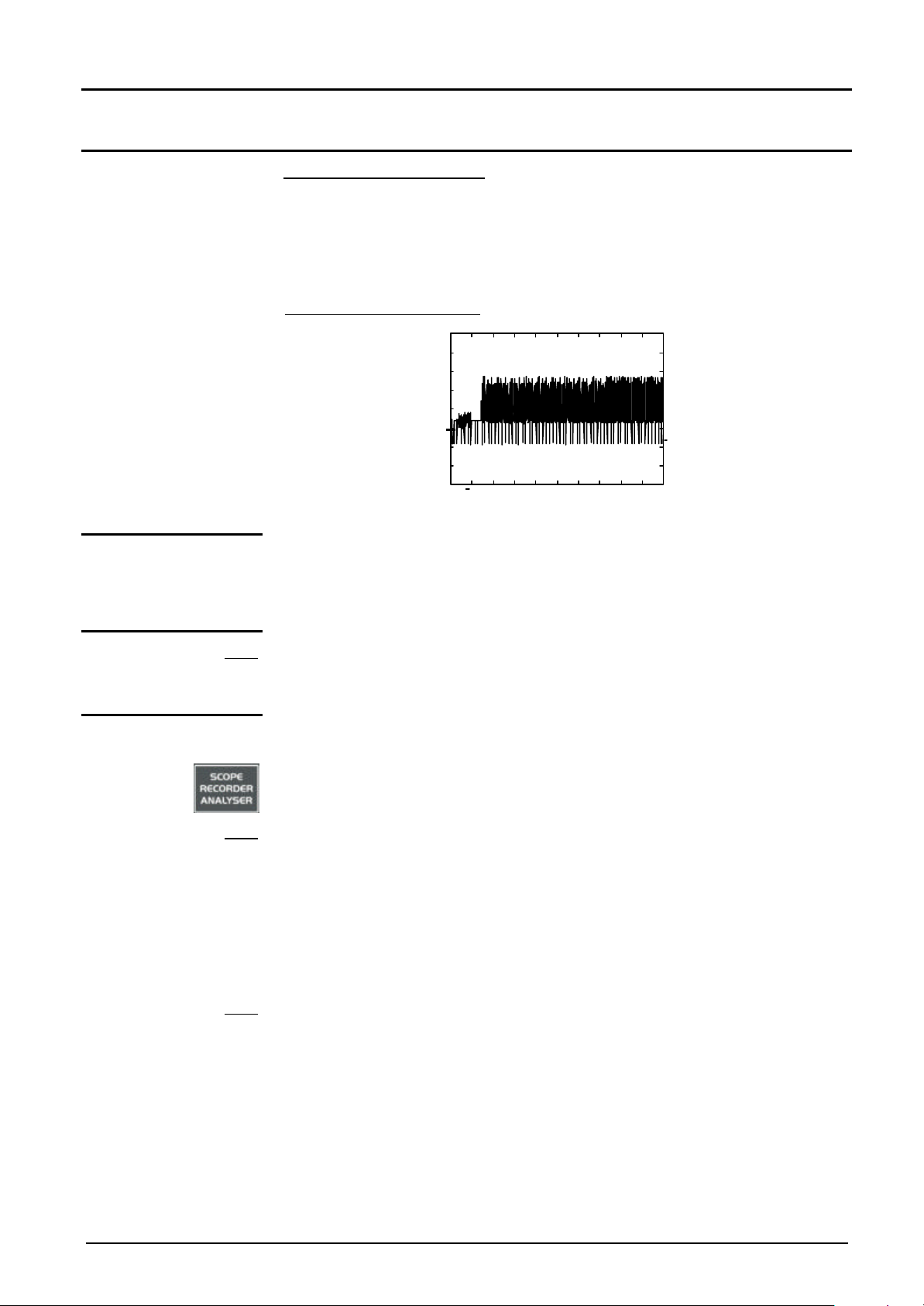
Functional Description (cont'd)
Examination of a TV frame
• In the Trigger Parameters menu (see §: Triggering), select TV-frame
coupling that permits pulse triggering on a frame sync.
• Modify the time base speed to 1 ms/div.
@ Example of TV frame
1
The synchronization train is clearly visible at the beginning of the screen.
Functional Description
Automatic
measurement in
Harmonic Analysis
mode
Note - Only the channels (and not the functions) can be the subject of harmonic
Note
Initially, there must be one or two traces on channels ch1 and/or ch2.
analysis.
- In this mode, the time base is not adjustable.
• Adjust correctly the ch1 and/or ch2 channel traces in the "Oscilloscope"
mode.
• Using the key shown opposite, select the "Harmonic Analysis" mode.
The ch1 channel trace is shown in a darker display, and the ch2 trace in a
lighter display.
• Select using the "Display" menu (see §. Display) the desired harmonic
breakdown.
- fundamental (F) and the first 15 harmonics
- even harmonics (from 2 to 30)
- odd harmonics (from 3 to 31) (+ fundamental)
Note
V - 60 Two-channel digital oscilloscope
The chosen selection appears under the breakdown display.
• The « SIGNAL » table under the breakdown indicates:
- the active channel(s) (ch1 and/or ch2)
- the rms. voltage of the signal in V
- the harmonic distortion factor (in %) of the signal
• The « PP» symbol on the fundamental (F) or on one of the harmonics
can be modified using the mouse left button to make measurements on
the selected harmonic.
Page 61
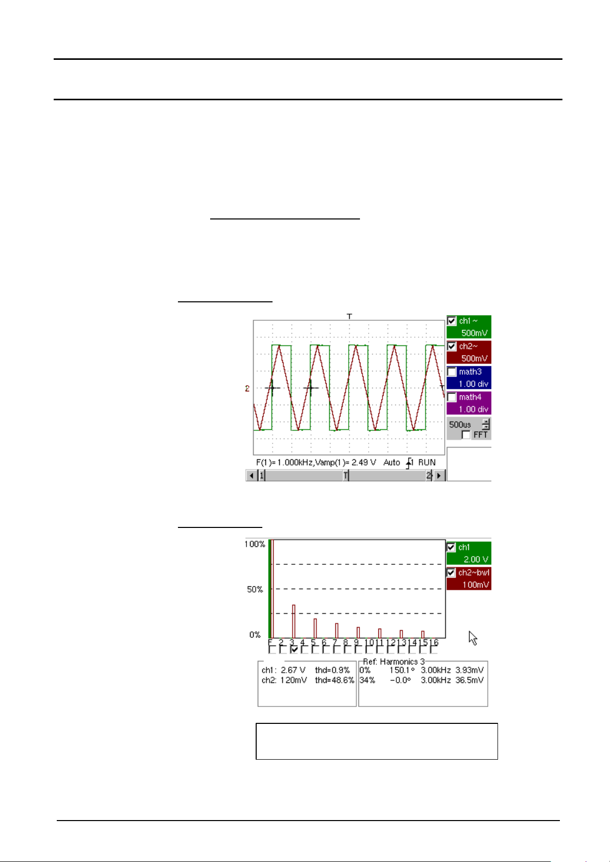
Functional Description
Functional Description (cont'd)
• The « Ref.: Harmonic X » » feeds into the selected harmonic:
- its value as a % of the fundamental
- its phase in ° with respect to the fundamental
- its frequency in Hz
- its RMS voltage in V
@ Example harmonic breakdown
On ch1 : the signal of the output calibrator (2.5 V, 1 kHz) (see §.
Calibration signal display)
On ch2 : triangular signal of 1 kHz and 2.5 V amplitude
Oscilloscope mode
Harmonics mode
Display « Odd Harmonics » selected
« Harmonics 3 » selected
Two-channel digital oscilloscope V - 61
Page 62

Functional Description (cont'd)
Functional Description
Display of slow
events
« ROLL Mode»
The purpose of this example is the analysis of slow events for time bases
ranging from 200 ms to 200 s.
The samples are displayed constantly without waiting for the Trigger
("Roll" mode).
@ Examination of a slow event
• Select the « Oscilloscope » mode.
• Inject to the CH1 input a sinusoidal signal at 1 Hz and 1 Vrms.
• Adjust the time base to 500 ms.
• Select Trace 1 : Menu : Vert → Display → Trace1.
• Select the sensitivity and coupling for ch1 : Menu : Vert → ch1 →
Sensitivity / Coupling:
- Channel Sensitivity : 500 mV
- Coupling : DC
• Select the trigger parameters : Menu : Trig → Parameters :
- Trigger source : CH1
- Trigger edge : +
• Select the « Single Shot » trigger mode : Menu : Trig → Single mode
• Using the mouse, move the trigger level symbol (Trigger) at (or down)
with respect to the display area.
G
G
If the trigger level is reached, the oscilloscope will stop data acquisition
once it has filled the acquisition memory (STOP mode).
• Start acquisition using the RUN/HOLD key (RUN mode).
Examination of a signal
The signal is constantly analysed (RUN mode).
V - 62 Two-channel digital oscilloscope
Page 63

Technical specifications
Only the values assigned with a tolerance or limits are guaranteed
Technical specifications
values (after half an hour warming-up). Values without a tolerance
are given for information only.
Vertical deflection
Characteristics Specifications Comments
Number of channels 2 channels: CH1 & CH2
Type of inputs Class 1, common grounds
Bandwidth at –3dB
Vertical offset dynamic
Input coupling AC: 10 Hz to 60 MHz (MTX 3252; MTX 3252-C)
BWL bandwidth limit at 20 MHz
Rise time MTX 3252; MTX 3252-C:
Cross-talk between channels
ESD tolerance ± 2 kV
Response to rectangular
signals 1 kHz and 1 MHz
Vertical rating accuracy
Vertical resolution
DC vertical measurement
accuracy
MTX 3252; MTX 3252-C:
> 60 MHz on all vertical ratings
from 2.5 mV to 5 V/div.
≥ 20 MHz on 10 V/div. ratings to
100 V/div.
MTX 3352; MTX 3352-C:
> 100 MHz on all vertical ratings
from 2.5 mV to 5 V/div.
≥ 20 MHz on ratings from 10 V/div.
to 100 V/div.
± 10 divisions on all ratings
- 100 MHz (MTX 3352; MTX 3352-C)
DC: 0 to 60 MHz (MTX 3252; MTX 3252-C)
- 100 MHz (MTX 3352; MTX 3352-C)
GND: reference
< 6 ns on all vertical ratings 2.5 mV to 100 V/div.
MTX 3352; MTX 3352-C:
< 3 ns on all vertical ratings 2.5 mV to 100 V/div.
DC at 20 MHz ≥ 35 dB
MTX 3252; MTX 3252-C:
20 MHz to 60 MHz ≥ 25 dB
MTX 3352; MTX 3352-C:
20 MHz to 100 MHz ≥ 25 dB
Overrun < 3 %
Aberration < 3 %
± 2 %
± 0.4 % of full scale
± [2 % (reading – offset) +
precision of vertical offset +
(0.05 div.) x (V/div.)]
Measured on 50 Ohm load with
6 div. amplitude signal
Same sensitivity on both channels
Positive or negative overshoot
Sequence of vertical
ratings 1 - 2 - 5
Variation in steps
(no variable continuous coefficient)
Vertical resolution 22
points per div.
Precision of vertical offset
Probes Take into consideration
Vertical ZOOM function on
acquired or backed up curve
Maximum input voltage 420 Vpk (DC + AC peak at 1 kHz)
Two-channel digital oscilloscope VI - 63
± [0.01 x (offset value) + 4 mV +
(0.1 div.) x (V/div.)]
attenuation factor of
probe in display
Zoom factors
without probes
560 Vpk (DC + AC peak at 1 kHz)
with probe 1/10 ref. HX0003
NB: the probe factor must be
brought in manually.
There is no automatic detection of
probe presence.
Page 64

Technical specifications (cont'd)
Vertical channels (cont'd)
Characteristics Specifications Comments
Technical specifications
Electrical safety 150 V, CAT II without probe
400 V, CAT II with probes
HX0003
Input impedance 1 MΩ ± 1 % approx. 13 pF
Display modes ch1, ch2
(300 V, CAT I; 300 V, CAT II)
Horizontal deflection (time base)
Characteristics Specifications Comments
Time base ratings 37 ratings, from 1 ns to 200 s/div. Sequence 1 - 2 - 5
Time base precision ± 0,5 %
Sampling frequency
Time measurement precision
Horizontal ZOOM The available horizontal
XY Mode
50 MS/s on 2 channels 100 MS/s
on one channel
precision ± 200 ppm
± [(0,04 div.) x (time/div.) + 0,005
x (reading) + 1 ns]
ZOOM factors range from
x 1 to x 200 depending on
sequence 1-2-5 (in ZOOM mode,
we have the same time base
criterion sequence as in normal
mode).
Bandwidth in X and Y identical
N.B.: The oscilloscope has a
recording memory capacity of
50 kpts per channel.
Horizontal screen resolution is
250 points for 10 divisions.
Bandwidth in X
and Y
Phase error
Ø 60 MHz (MTX 3252; MTX 3252-C)
Ø 100 MHz (MTX 3352; MTX 3352-C)
< 3°
In XY mode at each
G
instant t:
The smallest time increment
between two successive XY
points is given by the real
acquisition frequency of the
oscilloscope.
XY mode representation therefore
depends on the basic selected
time rating.
VI - 64 Two-channel digital oscilloscope
Page 65

Technical specifications
Technical specifications (cont'd)
Trigger circuit
Characteristics Specifications Comments
Trigger sources CH1, CH2, External, Mains
Trigger mode Automatic
Triggered
Single shot
Trigger coupling
without bandwidth
limit
Trigger slope Falling edge or
Trigger sensitivity
Sources CH1 and CH2
AC: BP 10 Hz to 60 MHz (MTX 3252; MTX 3252-C)
BP 10 Hz to 100 MHz (MTX 3352; MTX 3352-C)
DC: BP 0 to 60 MHz (MTX 3252; MTX 3252-C)
BP 0 to 100 MHz (MTX 3352; MTX 3352-C)
HFreject: BP 0 to 10 kHz
LFreject: BP 10 kHz to 60 MHz (MTX 3252; MTX 3252-C)
BP 10 kHz to 100 MHz (MTX 3352; MTX 3352-C)
TV-frame
TV-line Note: With band activated,
Rising edge
0,5 div. at 1 kHz
BW is limited to 20 MHz.
External source
Trigger level
Variation range ± 8 div.
50 mV
Acquisition chain
Characteristics Specifications Comments
ADC Resolution
Maximum sampling
frequency
Sampling modes
Real time
Equivalent time ETS
Transient capture
Minimum detectable Glitch
width (min/max acquisition)
Acquisition memory dept 50 Kbytes fixed
PRETRIG Function from 1 Kbyte to 50 Kbytes
CH1 and CH2 channel
saving memories
Storage formats Trace (.TRC) Save trace and acquisition
8 bits (20 LSB/div.)
50 MS/s
100 MS/s max. on one channel
50 MS/s max. on 2 channels
Accuracy ± 200 ppm
50 GS/s max.
≥ 20 ns
Saving of up to 4 files
each containing 50 kpts max.
Configuration (.CFG) Save complete equipment
Screen copy (.EPS) Standard image format
(.PRN)
File (.FCT) Saving of a function
1 converter per channel
Single non-repetitive
signals
Repetitive signals
Whatever time base used, shortterm events (Glitch, ≥ 20 ns) are
displayed.
Files assigned to names
parameters
configuration
Two-channel digital oscilloscope VI - 65
Page 66

Technical specifications
Technical specifications (cont'd)
Display
Characteristics Specifications Comments
Display screen LCD 5.7 STN Monochrome (MTX 3252; MTX 3352)
LCD 5.7 STN Color (MTX 3252-C; MTX 3352-C)
CCFL back-lit
Contrast Continuous adjustment
Resolution 1/4 VGA:
i.e.: 320 pixels horizontal
x 240 pixels vertical
Screen saver Time selectable in
Menu Util à Configuration
LCD zone reserved for traces 10 div. (H) x 8 div. (V)
i.e. 250 x 176
Displayed mode window
Normal
Complete memory
25 pts/div. (H)
x 22 pts/div. (V)
50 Kbytes
Horizontal ZOOM
Display modes
Vector
Envelope
Averaging
Graticule Complete Axes Borders
Indications on screen
Trigger
Traces
up to 250 pts from 50 kpts
of complete memory
Acquired points, interpolated
points, variable persistence,
averaging
The acquired points are attached
by a segment.
Min. and max. on each horizontal
screen position are displayed.
Factors ranging from 2, 4,16, 64
Trigger level position
(with overshoot indicator)
Trigger point position on bargraph
(with overshoot indicator)
Trace identifiers
Position, Sensitivity
Ground reference
Overshoot indicators
top and bottom if traces off screen
case of max. ZOOM x 200
Miscellaneous
Calibration signal Form
Amplitude
Frequency
VI - 66 Two-channel digital oscilloscope
rectangular
0 – 2.5 V ± 2 %
1 kHz ± 1 %
Page 67

Technical specifications
Technical specifications (cont'd)
Communication interfaces
SUBD 9-pin male connector
SUBD 25-pin female connector
for RS232C/CENTRONICS
interfaces
RS232C link configuration
USB Port serial B (option) used for connecting oscilloscope to PC.
A SUBD9-pin male connector is available on the back for
connecting a serial mouse.
The RS232C and CENTRONICS interfaces use the same SUBD
25-pin female connector on the back of the unit.
Selection of speed in Bauds
300, 600, 1200, 2400, 4800, 9600, 19200, 38400, 57600, 115200
Parity selection
None, even, odd
Word length selection
8 bits or 7 bits
Stop bit number selection
1 or 2 stop bits
Protocol selection
Hard (for RTS and CTS lines)
Soft (for XON and XOFF characters)
None (no protocol)
Location on rear of unit
Connector rear panel type B
Specification conforms to USB Rev. 10
Speed 1.5 Mbps, 12 Mbps
ETHERNET Interface (option) Location rear panel of unit
Type 10BASE-T (Twisted Pair)
Connector RJ 45 8 points
Standard IEEE 802.3
6-pin Mini-Din 6 connector
(option)
for connecting PS2 mouse.
Location on rear of unit
Connector 6-pin Mini-Din
Remote program of
oscilloscope by a PC
The oscilloscope can be programmed at a distance with a
computer or PC using simple standardized commands and the
RS232C interface (or the series B USB port as an option) for
transferring data from or to the recording memory.
The programming instructions comply with the IEEE 488.2
standard, SCPI protocol.
Refer to the remote programming manual for the list of
commands.
Two-channel digital oscilloscope VI - 67
Page 68

General characteristics
EMC
•
Environment • Reference temperature 18°C to 28°C
• Operating temperature range 0°C to 40°C
• Storage temperature range -20°C to +70°C
• Use indoor
• Altitude < 2000 m
• Relative humidity < 80 % at up to 31°C
General characteristics
Mains power
supply
Safety
• Network voltage Use nominal range 100 to 240 VAC
• Frequency from 47 to 63 Hz
• Consumption < 12 W at 230 VAC, 50 Hz
• Fuse 2,5 A / 250 V / delayed
• Removable power supply cord
As per IEC 61010-1 (2001) :
• Insulation class 1
• Pollution degree 2
• Power supply overvoltage category CAT II 240 V
• "Measurement” input overvoltage category CAT II 150 V or
CAT I 300 V
This equipment is designed to conform to current EMC standards and its
compatibility has been tested as per NF Standard EN 61326-1, 07/97 +
A1, 10/98 :
Immunity influence magnitude: 2 div. in presence of 3 V/m
electromagnetic field
Mechanical characteristics
Case
Packaging
VII - 68 Two-channel digital oscilloscope
Size Screen shutter open 300 (H) x 270 (l) x 195 (D) in mm
Screen shutter closed 170 (H) x 270 (l) x 195 (D) in mm
• Weight approximately 3.3 kg
• Materials ABS VO (self-extinguishing)
• Tightness IP 30
• Size 308 (l) x 338 (L) x 338 (D) in mm
Page 69

Supply
•
•
Supply
Accessories
Supplied with
instrument
Supplied as an
option
• Operating manual and programming manual for CD ROM
• Mains power supply cord
• Safety probes (x 2)
• Serial mouse with SUBD 9-pin connector
• Mouse mat
• Takeoff Tee
1 x BNC male - 2 x BNC female (package of 3 u.) HA2004-Z
• BNC female - BNC female extender (package of 3 u.) HA2005
• Safety adapter
BNC male / 4 mm socket, CAT III, 500 V (package of 3 u.) HA2002
• Safety adapter
BNC male / 4 mm plug, CAT III, 500 V (package of 3 u.) HA2003
• Safety adapter
BNC male / 4 mm socket, CAT III, 500 V (package of 2 u.) HA2053
• Voltage probe 1:10 fixed, 150 MHz, CAT II / 400 V HX0003
• Voltage probe 1:10 fixed, 450 MHz, CAT II / 1000 V HX0005
• Voltage probe 1:100 fixed, 300 MHz, 5 kV Peak HX0006
Spares
Differential probe 30 MHz MX9003-Z
• BNC male / BNC male cord CAT III, 500 V, length 1 m AG1044
• BNC male / BNC male cord CAT III, 500 V, length 2 m AG1045
• RS232C – 9-pin male / 25-pin female adapter AS0204
• IEEE / IEEE cable, length 1 m AG0368
PC transfer software SX-METRO2
• Labwindows and Labview Drivers (VISA standard)
available on the NATIONAL INSTRUMENTS site
(www.natinst.com)
• Digital plotter (A3 / A4) CA 991
• Carrying bag AE0189
• Field kit HX0024
• 2.5 A, 250 V, T, 5 x 20 mm AT0090
Oscilloscope numérique à 2 voies VII - 69
 Loading...