

Page 1
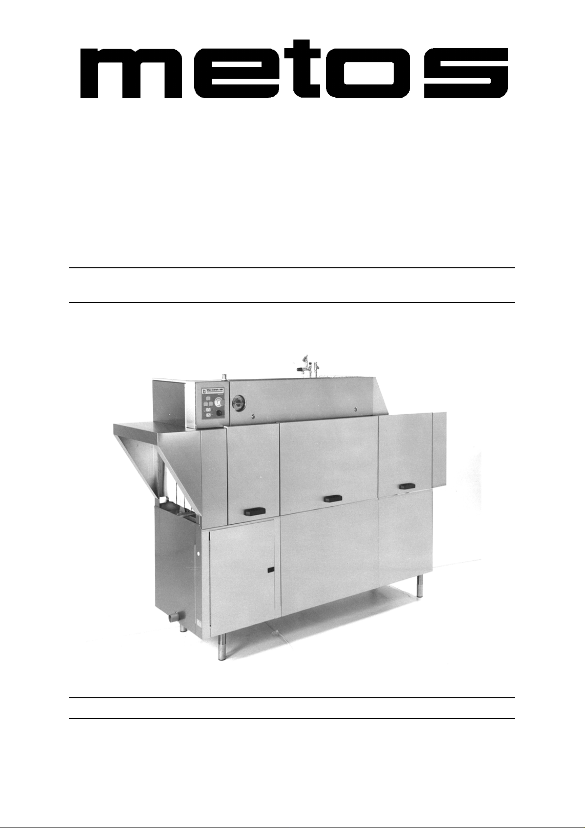
RACK CONVEYOR DISHWASHER
ELECTRICALLY HEATED
STEAM HEATED
TYPE: 151E
Accessories
FS40
Installation and Operation Manual
From S/N: Rev.: 2.2
Page 2

Page 3

4.12.2000 Rev. 2.2
Dear Customer,
Congratulations on d eciding to cho ose a Metos equ ipment for y our kitchen ac tivities. Yo u
made an excellent choice. We will do our best to make also you a satisfied Metos customer like thousands and thousands of others all over the world.
Please read this manual carefully. You will learn many right, safe and efficient working
methods in order to get the best possible benefit from the equipment. The instructions and
hints in this manual will gi ve you a qui ck and eas y start in us ing this equ ipment. You will
note very quickly how nice it is to use the Metos equipment.
All rights are reserved for technical changes.
You will find all the main technical data on the rating plate fixed to the equipment. When
you need service or technical help, please let us know the serial nu mber of the equipm ent.
This will make it easier to provide you with the correct service. Please write the contact
information of your local Metos service in advance on the lines below.
METOS TEAM
Metos service phone number:................... ............................. ............................ ...................
Contact person:....................................................................................................................
3
Page 4
4.12.2000 Rev. 2.2
4
Page 5

4.12.2000 Rev.
1. General .......................................................................................................... 7
1.1 Symbols used in the manual .......................................................................................... 7
1.2 Symbols used on the appliance ...................................................................................... 7
1.3 Checking the relation of the appliance and the manual ................................................. 7
1.4 Rating plate information ................................................................................................ 8
1.5 Staff training .................................................................................................................. 8
2. Safety .............................................................................................................. 9
2.1 Safe use of the appliance ............................................................................................... 9
2.2 Safety instructions in case of malfunction ..................................................................... 9
2.3 Disposal of the appliance ............................................................................................... 9
2.4 Other prohibitions .......................................................................................................... 9
3. Functional description ................................................................................ 10
3.1 Application of the appliance ........................................................................................ 10
3.1.1 Use for other purposes ......................................................................................... 10
3.2 Construction ................................................................................................................ 10
3.3 Control panel .............................................................................................................. 12
4. Operation instructions ............................................................................... 14
4.1 Before use .................................................................................................................... 14
4.1.1 Preparing the operation ........................................................................................ 14
4.2 Operation ..................................................................................................................... 14
4.2.1 Start of dishwashing ............................................................................................ 14
4.2.2 Dishwashing ........................................................................................................ 14
4.3 After use ...................................................................................................................... 15
4.3.1 Cleaning .............................................................................................................. 15
5. Installation ................................................................................................... 17
5.1 General ........................................................................................................................ 17
5.2 Operating conditions ................................................................................................... 17
5.2.1 Lighting ................................................................................................................ 17
5.2.2 Ventilation ........................................................................................................... 17
5.3 Electrical connection ................................................................................................... 18
5.4 Water connections ....................................................................................................... 18
5.5 Drain connection ......................................................................................................... 18
5.6 Steam connection ......................................................................................................... 18
5.7 Measures after installation ........................................................................................... 18
5
Page 6
4.12.2000 Rev.
5.8 First start, test run ........................................................................................................ 19
6. Adjustments ................................................................................................ 20
6.1 Setting the DIP switches .............................................................................................. 20
6.1.1 Setting the machine model .................................................................................. 20
6.1.2 Setting the machine type ..................................................................................... 20
6.1.3 Setting the accessories ....................................................................................... 20
6.1.4 Setting the language to the machine with text panel .......................................... 20
6.2 Adjusting the final rinse ............................................................................................. 21
6.3 Adjusting the reference values ................................................................................... 21
6.4 Controlling the infeed conveyor ................................................................................. 23
6.5 Controlling the dryer .................................................................................................. 23
6.6 Setting the filling memory to zero .............................................................................. 23
7. Troubleshooting .......................................................................................... 24
8. Spare parts .................................................................................................. 27
8.1 Voltage codes .............................................................................................................. 29
8.2 Product codes ............................................................................................................... 29
9. Technical specifications ............................................................................ 101
6
Page 7
General
1. General
4.12.2000 Rev. 2.2
Carefully read the instructions in this manual as they contain important information regarding proper, efficient and safe installation, use and maintenance of the appliance.
Keep this manual in a safe place for eventual use by other operators of the appliance.
The installation of this appliance must be carried out in accordance with the manufacturer’s instructions and following local regulations. The connection of th e appliance to the
electric and water supply must be carried out by qualified persons only.
Persons using this appliance should be specifically trained in its operation.
Switch off the appliance in case of failure or malfunction. The periodical function checks
requested in the manual must be carried out according to the instructions. Have the appliance serviced by a technically qualified person author ized by the m anuf actu rer and u sing
original spare parts.
Not complying with the above may put the safety of the appliance in danger.
1.1 Symbols used in the manual
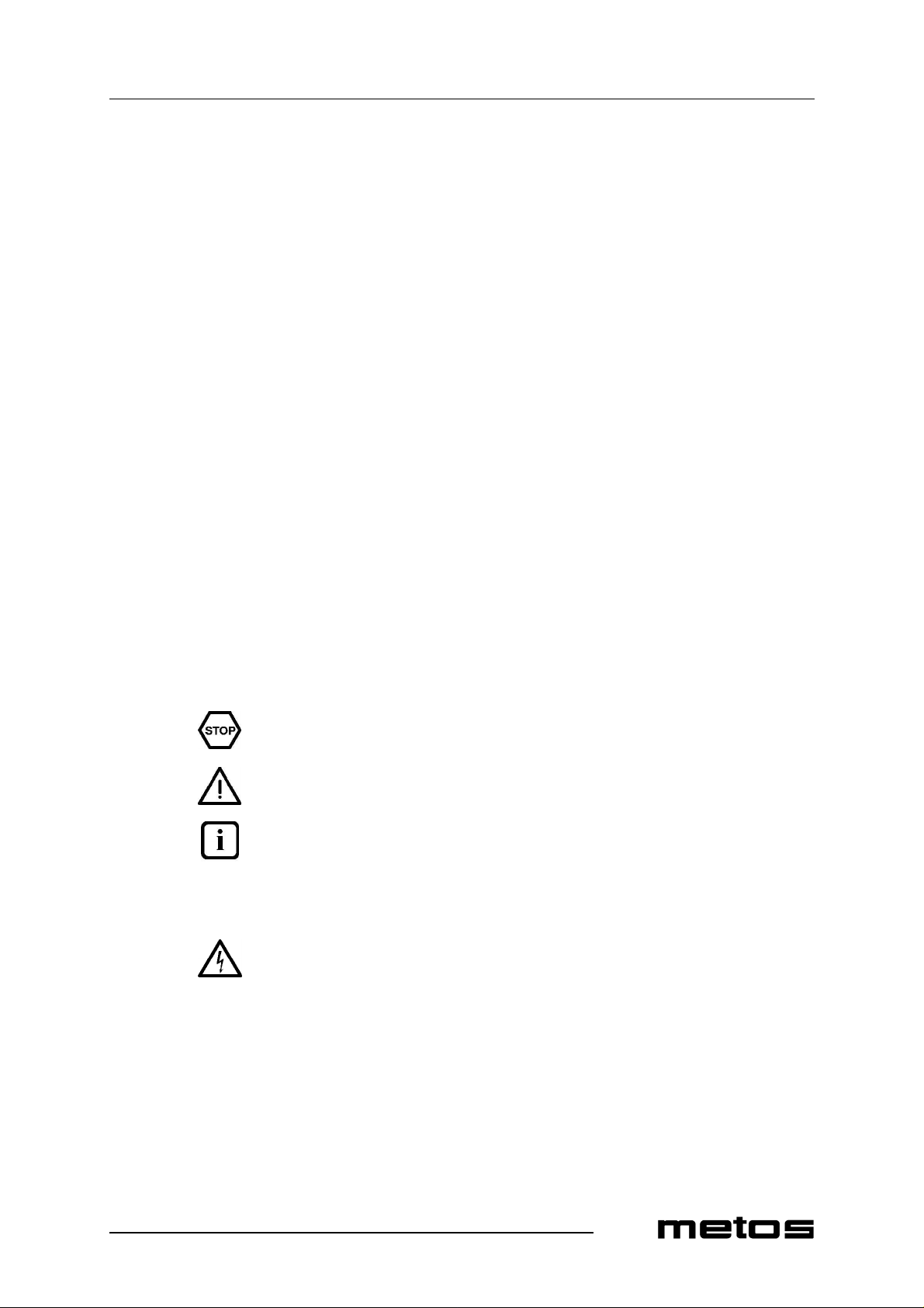
This symbol informs about a situation where a safety risk might be at hand. Given instructions are mandatory in order to prevent injury.
This symbol informs about the r ight way to perfo rm in order to prevent bad res ults , appli ance damages or hazardous situations.
This symbol informs about recommendations and hints that help to get the best performance out of the appliance.
1.2 Symbols used on the appliance
This symbol on a part informs about electrical terminals behind the part. The removal of
the part must be carried out by qualified persons only.
1.3 Checking the relation of the appliance and the manual
The rating plate of the appliance indicates the serial number of the appliance. If the manuals are missing, it is possible to order new ones from th e manufacturer or the lo cal representative. When ordering new manuals it is essential to quote the serial n umber shown
on the rating plate.
7
Page 8
General
1.4 Rating plate information
The rating plate of the appliance is located in the lower section of the machine, at either
loading or unloading end. The technical data provided by the rating plate are also shown
in the machine’s circuit diagrams. The field contents are as follows:
1. Machine type
2. Manufacturing number
3. Manufacturing year
4. Sealing class
5. Voltage
6. Number of phases, nollajohdin
7. Frequency
8. Main fuse
9. Motor power
10. Electrical heating power
11. Maximum power
4.12.2000 Rev. 2.2
1.5 Staff training
Before taking the machine into use, make sure that the staff receive the requisite information for handling and maintenance!
8
Page 9
Safety
2. Safety
2.1 Safe use of the appliance
Do not touch the interior parts of the washing space while the machine is runn ing. Do not
either operate the machine when the cover plates have been detached.
Pinch risk: The reciprocating movement of the conveyor may cause a risk of squeezing
in the immediate vicinity of the loading and unloading openings, the angle feeder or the
mechanical curves.
4.12.2000 Rev. 2.2
2.2 Safety instructions in case of malfunction
In case of electricity breakdown, switch the power off with the main switch.
Check the following:
• Has the appliance been used according to instructions?
• Are all possibly removable parts refitted?
• Is the main switch in the ON position?
• Are the circuit breakers (fuses) of the appliance in the main fuse box in working
order? Ask an authorized person to check the circuit breakers.
• If this does not help, contact an authorized service person.
2.3 Disposal of the appliance
The disposal of the appliance when its economical lifetime h as been reach ed must be carried out in accordance with local rules and regulations. Contact professional personnel
specializing in recycling.
2.4 Other prohibitions
Only use detergents intended for machine dish wa sh ing. Follow the instructions provid ed
by the detergent supplier.
Use protective gloves or goggles when handling the detergent. Observe the warnings on
the detergent container.
9
Page 10
Functional description
3. Functional description
3.1 Application of the appliance
The appliance is designed for washing dishes used in food serving, food preparation and
food storing. A detergent intended for machine dishwashing must be used.
3.1.1 Use for other purposes
Always consult the manufacturer, if you intend to use the appliance for other purposes
than mentioned above.
4.12.2000 Rev. 2.2
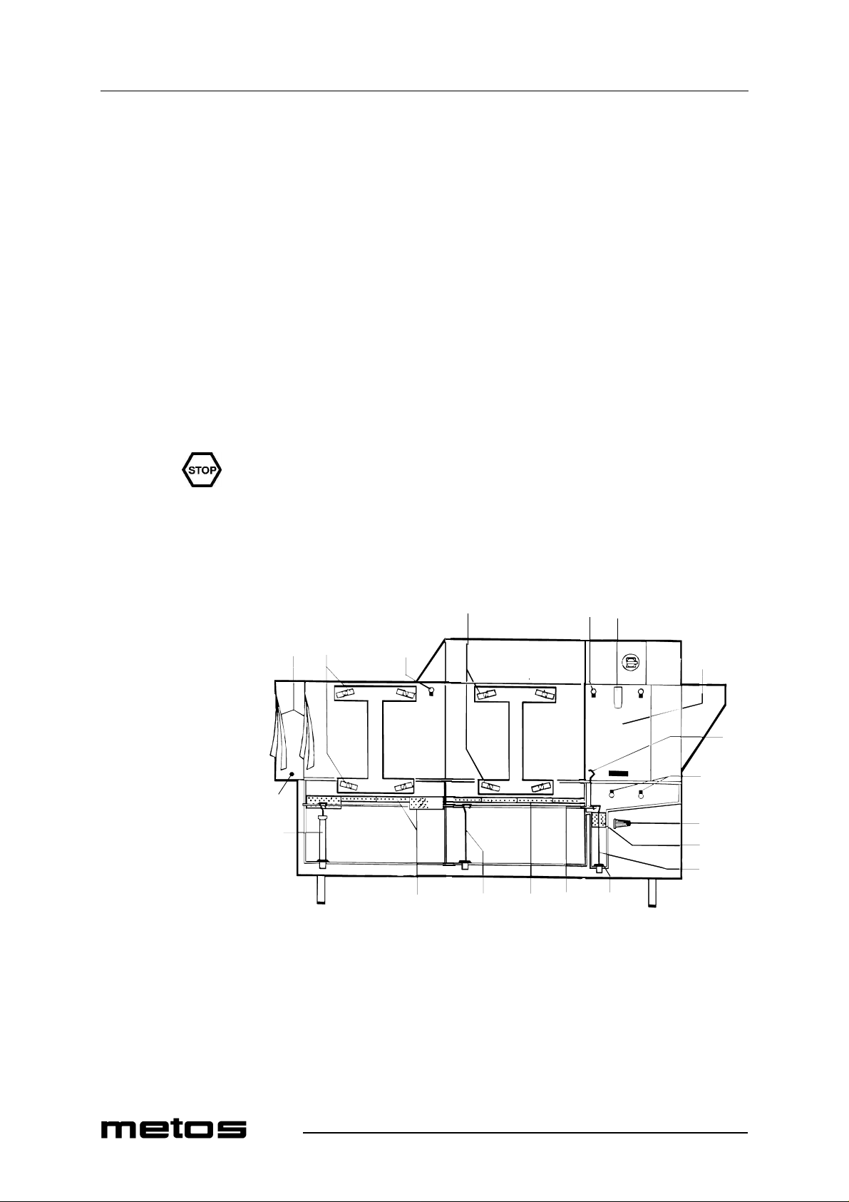
3.2 Construction
2 3 4
1 2 3
5
6
3
14
7
13
8
9
12 9 12 11 10
10
1. Curtains
2. Wash arms
3. Rinse nozzles
4. Door catch
5. Door
6. Tank drain lever
Page 11

Functional description
4.12.2000 Rev. 2.2
7. Final pump rinse filter
8. Final rinse filter
9. Drain plug
10. Rubber gasket
11. Overflow pipe and drain plug lift shaft
12. Strainer plates
13. Overflow pipe
14. Start switch
11
Page 12
Functional description
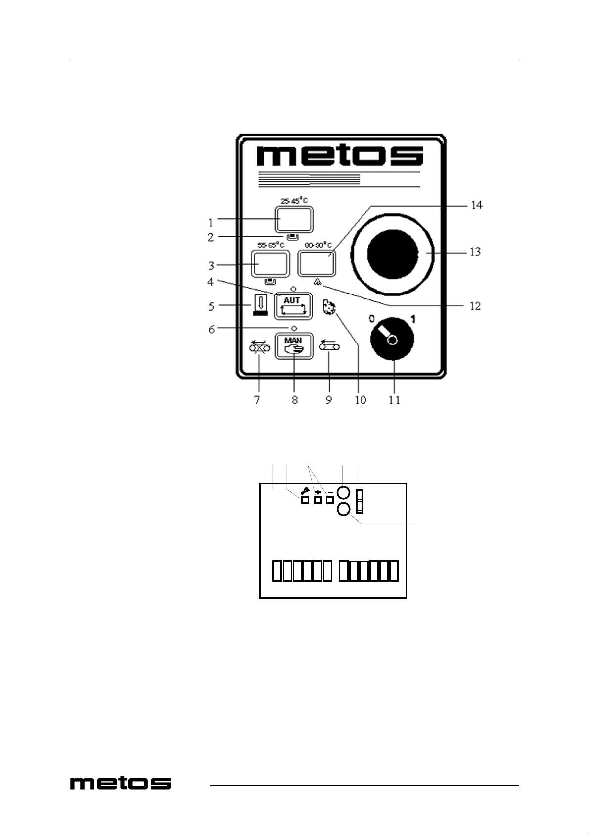
3.3 Control panel
4.12.2000 Rev. 2.2
15 16 17 18 19
20
1. Temperature display pre wash (WD-211E, 241E, 331E)
2. Signal light for low water level in corresponding tank
3. Temperature display power wash
4. Push button for wash with automatic stop
5. Door open signal light
6. Signal light for selected wash method
7. Signal light; machine’s overload or stop emergency activated
8. Push button for wash without automatic stop
9. Signal light; infeed / outload conveyor overload or unload table switch activated
12
Page 13

Functional description
4.12.2000 Rev. 2.2
10. Signal light for overloads of pumps and condensor fan
11. Control switch
12. Signal light; final rinse filter (8) blocked
13. Emergency stop push button
14. Temperature display final rinse
15. Circuit board
16. Diagnosis button
17. Push buttons for adjustment of reference values
18. Potentiometer (vacant)
19. DIP switches
20. Potentiometer for infeed conveyor
13
Page 14
Operation instructions
4. Operation instructions
4.1 Before use
4.1.1 Preparing the operation
• Make sure that the machine has been cleaned and that the water supply valves are
in the OPEN position.
• Put the overflow pipe and the drain plugs in place. Make sure that they are properly
fastened to the lift shaft (11).
• Check the condition of rubber gaskets (10).
• Put the strainers and curtains in place.
• Check the amount of detergent and rinse aid.
• Close the doors.
4.12.2000 Rev. 2.2
4.2 Operation
4.2.1 Start of dishwashing
Turn the machine’s control switch (11) to position 1 and wait until the tanks fill and the
water heates up. The filling time is approx. 6-13 minutes. In dishwashers connected to
cold water supply, the filling time is 30 minutes at the max i mum. When the temperatures
are clearly visible on the displays (1, 3, 14) the machine is ready for dishwashing.
Push the button AUT. The machine starts and runs for a moment for mixing the detergent.
4.2.2 Dishwashing
Remove loose food residues and rack the d ishes.Rack the tr ays longitudinally to machine.
If GN containers are washed in the machine, they must be placed in a special rack and fed
into the machine longitudinally.
Choose the wash method AUT or MAN.
• AUT = Wash with an automatic stop. The dishwasher starts when a rack is fed in.
The rack remains within the wash zone until the next rack pushes it on. The dishwasher stops automatically if no new rack is fed in.
• MAN = Wash without an automatic stop. The dishwasher starts immediately. The
MAN position is preferable for heavily soiled wash items. If only o ne rack is fed,
14
Page 15
Operation instructions
4.3 After use
4.3.1 Cleaning
4.12.2000 Rev. 2.2
it stops and is processed in the wash zone for a duration that can be d ecided by the
operator. The rack will be pushed out of the dis hwasher when a new rack is fed in.
We recommend to feed in racks at the following intervals:
approx. 50cm
Increase the distance if the wash items are heavily soiled.
The temperature of the rinsing water is approx . 85ºC. Do not open the machine doors until
the washing process is completed.
Cleaning: The temperature of wash water in the power wash tank is approx. 60ºC and it
is mixed with detergent. Be careful when em ptying and cleaning the tanks. Use pr otective
gloves.
Use of a pressure washer for cleaning the machine is forbidden.
Do not use steel wool for cleaning the machine. Use of steel woo l may cause rust spots on
the machine surfaces. Do not either use detergents that, if not thorougly rinsed from surfaces, form foam during the wash process, thus impairing the wash result. Consult your
detergent supplier for the correct type of detergent.
It is not allowed to clean the outside of the machine with a jet of water.
For cleaning the outer surfaces, wiping with a damp cloth will often suffice.
When washing floors, water can splash up from the floor, thus damaging electric components, which are not designed to withstand rinsin g with water. Special pr otective covers
should be used to protect the machine from water splashes, if the floor is washed with a
pressure washer.
Daily cleaning
• Turn the control switch (11) to position 0.
• Empty the tanks by pulling the tank drain level (6).
• Clean the tank strainers (12), tanks, curtains and wash nozzles. Clean the final
rinse filter (8). Dry the rubber lists of the doors. The rubber lists are located on the
rear side of the door, in the door’s upper section. Leave the doors open.
• Clean the outer surfaces of the machine with a damp cloth. Do not use steel wool
for cleaning. Use of steel wool may cause rust spots on the machine surfaces.
15
Page 16
Operation instructions
4.12.2000 Rev. 2.2
Basic cleaning of a returning unit equipped with a conveyor
• Stop the conveyor with the stop switch
• Spray the system with non-foaming general cleaning liquid or desinfecting detergent. Your detergent supplier can recommend you the best product for this purpose. The conveyor materials stand up to all normal detergents that are used in
kitchen.
• Let the detergent act for 10-15 minutes or a length of time recommended by the detergent supplier.
• Clean more dirty places e.g. with a brush.
• Rinse the system thoroughly, don’t rins e electric parts like control boxes and electric motors.
Follow the dosing and safety instructions given by the detergent supplier.
Weekly cleaning and maintenance when needed
• Wash arms (2): Detach the wash arms and clean them inside. Clean the wash arm nozzles.
• Rinse nozzles (3): Clean.
• Final pump rinse filter (7): Clean the filter 2-3 times a week or more often depending on the use of the machine. The filter is located in the final rinse zone, behind
the door in the lower section of the machine. The final rinse tank must be empty
when cleaning the filter. Detach the filter cover by turning it counterclockwise.
Clean the filter and put it carefully back into place.
• Doors (5): The doors can be detached for cleani ng. Lift the door to t he upper pos ition and press the door catch (4) backwards. The door can be completeley lifted
out for cleaning. When the door is put back into place, make sure that the list, on
which the door is placed, is fitted in the groove of the catch (4).
16
Page 17
Installation
5. Installation
See the technical specifications and the installation drawing.
5.1 General
Electrical, water and steam connections have to be done by an authorized installation
company.
Make sure that the main voltage is the same as indicated in the rating plate of the machine.
4.12.2000 Rev. 2.2
Check the tightness of the connections before starting the machine. See also the installation instructions.
5.2 Operating conditions
5.2.1 Lighting
To get the best possible working conditions, the machine should be placed in a room with
adequate general lighting.
5.2.2 Ventilation
A satisfactory working environment requires adequate ventilation in the dishwashing room.
17
Page 18
Installation
5.3 Electrical connection
For details, see the installation drawing and the connection drawing in chapter “Technical
Specifications”.
There is an electrical wiring diagram inside the electric box door (3). Keep this in the electric box also after installation.
The main switch (2) has been constructed inside the machine. Connect the cable to the terminal board (1). NOTE. In special cases the electrical feed can be drawn from the floor.
In this case, the cable is drawn under the cover plates (13).
Check the correct rotating direction of the pumps in use when the tanks have filled with
water. The rotating direction has to be the same as indicated by the arrow on the pump. If
the rotation direction is wrong, stop the machine and change two phases of the cable in
the terminal board.
5.4 Water connections
4.12.2000 Rev. 2.2
The pipe connection pieces are packed inside the machine.
Adjust the machine horizontally with the feet. Connect the cold and warm water feed (4,
5). There are filters inside the pipe connections.The water connections have to be
equipped with stop cocks. In machines where the water connectios are taken from the
floor, warm and cold water connection points are (8, 9).
5.5 Drain connection
The drain connection (10) can be led either to the right or to the left. Connect the drain
pipe to (A) and draw it to the floor gulley so that the pipe ends above the water level. Remove the hole cover from the appropriate side of the cover plate (B) and take the drain
pipe trough it.
5.6 Steam connection
If the machine is steam heated, connect pipes for steam an d condensation water to the connection point (11).
5.7 Measures after installation
18
When the tanks have been filled with water, check once more that th e machine is standing
horizontally. Close the doors an d check that the d oors are in straigh t line.I f necessary, ad just with the feet.
Page 19
Installation
5.8 First start, test run
Place the overflow pipe, the drain plugs, the strainer plates and the curtains. Close the doors.
Make sure that the automatic fuse FU/M in the electric box is on. Turn the control switch
to position ’1’, the tank filling starts.
NOTE! To avoid the burning of boiler heating elements, there is so called filling memory
in the machine which allows you to check if the boilers of the machine are filled or empty.
When the machine is delivered from the factory, the boilers are emptied and the filling
memory is set to zero. When the control switch of th e machine is turned t o position ’1’,
the tanks and the boilers fill with water. The boilers are filled via the solenoid valve Y02.
When the valve Y02 is open, a red l ight on the card is li t. If the relay light is no t on, th e
boilers do not fill and the heating elements may burn. IMMEDIATELY SWITCH OFF
THE MACHINE and set the filling memory to zero. See chapter “Adjusting reference
values” to set the filling memory to zero.
The filling time in the warm water connected machine i s appr. 6-13 minute s. The filling
time in the cold water connected machine is 30 minutes at the maximum.
4.12.2000 Rev. 2.2
Test the machine with racks, check the temperatures of the tanks and the final rinse. Check
that the machine does not leak from water and detergent connections.
The CE mark is only valid for the machine of original design.
19
Page 20
Adjustments
6. Adjustments
6.1 Setting the DIP switches
For correct functioning of the different zones and accessories, the right setting of the DIP
switches according to the machine and accessories has to be ensured. There are 8 pieces
of DIP switches (15) on the card that can be set either to ‘ON or ‘OFF’ position.
6.1.1 Setting the machine model
4.12.2000 Rev. 2.2
DIP switch 4 OFF (Warm water connected machine)
DIP switch 4 ON (Cold water connected machine)
6.1.2 Setting the machine type
6.1.3 Setting the accessories
DIP switch 3 ON (Continuous feeding, angle loading table or mechanical curve)
DIP switch 5 ON (Pre rinse zone)
6.1.4 Setting the language to the machine with text panel
DIP switch 6 ON – 7 and 8 OFF: English text
DIP switch 7 ON – 6 and 8 OFF: Dutch text
DIP switch 8 ON – 6 and 7 OFF: Finnish text
20
DIP switch 6, 7, 8 OFF: Swedish text
DIP switch 6, 7, 8 ON: German text
DIP switch 6,7 ON – 8 OFF: French text
Page 21

Adjustments
6.2 Adjusting the final rinse
The final rinse flow is adjusted with the reducing valve that is in the solenoid valve box
(6, see the installation drawing) beside the water meter.
Lock the switch arm (7) for the pumps start at the infeed end and the final rinse switch
arm (12) behind the final rinse door. Close the doors and push the MAN button.
Read the flow from the meter BV02. The flow has to be:
6 l/min
Release the switch arms after the adjustment.
6.3 Adjusting the reference values
The tank temperatures, wash time etc. can be checked and adjusted on the circuit board
with the diagnosis function. The diagnosis includes a number of texts divided into three
tables. Each table has a line number 01, 02 etc. Reference values can also be adjus ted with
the service instrument that is connected to the circuit board. In this case all the machine’s
messages are shown on the display of the service instrument in clear text.
4.12.2000 Rev. 2.2
• Check that the DIP switches are set to the correct machine type (see table Setting DIP switches)
• Hold the diagnosis button (16) pushed in for a few seconds. The first line number
1 in Table 1 is now s how n on t he di sp l ay (3). The display ( 14) sh ow s a v al ue. The
values shown on the display (14) are either real values, e.g. actual temperature in
a tank, or an adjustable reference value.
• The button (16) allows you to move forward to the next line number.
• The reference values are adjusted with the buttons + and- (17)
• Moving between tables: When line number 01 in Table 1 is shown on the display
(3), push +. Line number 40 is now shown in Table 2. Pushing + again shows the
basket counter in Table 3.
• On completion of checking and adjusting, hold the button (16) pressed until the
displays (3) and (14) return to normal temperature displaying.
21
Page 22
Adjustments
4.12.2000 Rev. 2.2
Table 1: Adjusting the reference values
Display (3)
Line No
03 Temp. power wash 1 - 04 Ref. value power wash 1 60°C 40-95°C 05 Temp. boile r 3 - 06 Ref. value boiler 3 80°C 70-95°C 07 Temp. boile r 1 - 08 Ref. value boiler 1 80°C 60-95°C 09 Temp. boiler 2 (final rinse) - 10 Ref. value boiler 2 (final rinse) 85°C 70-95°C 11 Temp. condensing battery - 12 Ref. value condensing battery temp. 30°C 10-60°C 13 Timer condensing fan 5 sek 1-90 sek 14 Wash time (50 Hz frequency) 60 sek 40-180 sek 15 Off delay conveyor infeed 2 sek 0-10 sek
Refers to Display (14)
Ref. value
Setting area
Table 2
Remarks
Display (3)
Refers to Display (14)
Line No.
40 Filled boilers 0 or 1* 41 Final rinse flow l/min** 42 Extended delay time interval for feed. Applies to machine with drying zone and
conveyor curve on outfeed
43 Motorized infeed conveyor 0 or 1*
* 0 = unactivated, 1 = activated
** if the flow falls below 4l/min, the symbol (12) flashes.
Table 3: Rack counting
Both displays (3) and (14) together show the number of racks up to 9999. By pushing the button (16), the number of racks
will be shown in tens of thousands.
0 or 1*
22
Page 23
Adjustments
6.4 Controlling the infeed conveyor
The infeed conveyor runs generally together with the feeding of the machine. To get the
correct distance between the racks fed in, the conveyor can tempo rarily b e stop ped. With
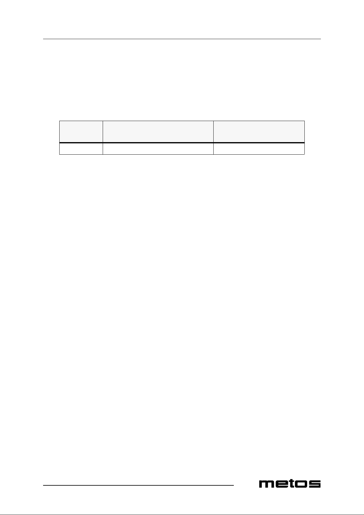
the aid of the potentiometer P1 (20) on the printed circuit card, a stop time for the rack can
be decided. (Table 4)
Table 4
4.12.2000 Rev. 2.2
Machine
Stop time infeed conveyor Potentiometer P1
type
151E 15 sec 0-30 sec
6.5 Controlling the dryer
The possible dryer in the machine is controlled in parallel with t he machine infeed. The
wash time (table 1, line No. 14) is increased by 60 second s compared to the machine without the dryer.
6.6 Setting the filling memory to zero
When emptying the boilers you have to set the filling memory to zero (adjusting the rf.
values line 40 = 0) or to disconnect the connector J9 on the circuit board.
setting area
23
Page 24
4.12.2000 Rev. 2.2
Troubleshooting
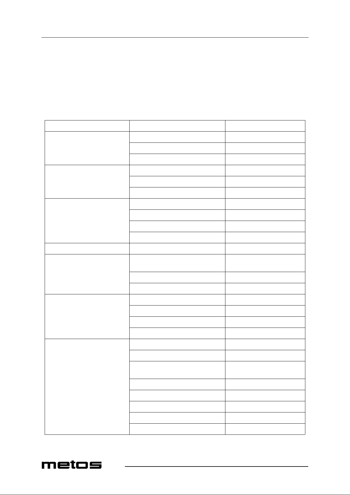
7. Troubleshooting
PROBLEM POSSIBLE CAUSE MEASURES Tank fills slow ly Mud separator blocked Clean mud separator
Solenoid valve defective Call the service Pressure switch defective Call the service
Tank fills not to the right level Overflow pipe leaks or ismissing Check and put in place
Pressure switch defective Call the service Solenoid valve defective Call the service
Tank temperature is not correct Heating element defective Call the service
Fuse blown out Call the service Pressure switch defective Call the service
Thermoelement defective Call the service Final rinse temperature is not corre ct Fu se blow n ou t Call the service Machine doesn’t start Roller table switch activated Remove rack from the end of roller
table Door is not properly closed Close the door Conveyor overload protection activated Remove obstacles from conveyor
Steam exhausts from the machine’s end
Poor wash result Too short washing time Feed racks with longer distance
Condensor’s outblow opening covered Check and remove obstacles Condensor fan defective Call the service Amount of incoming water too low Call the service Curtains are not in their places Check and put in place
Dishes placed incorrectly in the rack Correct placing Dirt dried on dishes Soak dishes before feeding into
machine
24
Wash or rinse nozzles blocked Check and clean Tank strainers incorrectly placed Check and pu t in place correctly Curtains are not on their places Check and put in place Detergent or rinse aid dosing wrong Call the detergent supplier Temperatures wrong Call the service
Page 25
4.12.2000 Rev. 2.2
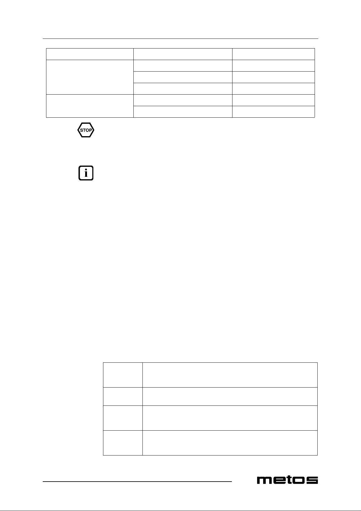
Troubleshooting
Pump defective Call the service
Dishes don’t dry Rinse nozzles blocked Check and clean
Rinse aid dosing wrong Call the dete r gent supplier Final rinse temperature too low Call the service
Dishes tip over in racks Dishes incorrectly placed Correct placing
Nozzle pressure too higa Call the service
Always call the service if you have to open cover plates.
Alarm
Malfunctions in the machine’s operation are indicated on the control panel. The signal
lights (5, 7, 9, 12, 13) are blinki ng ind icatin g differen t malfun ctions . The dis plays (3 ) and
(14) indicate different errors (’Err01’, etc.). Malfunctions in the circuits that are measuring temperatures are indicated on the corresponding temperature display with numbers 0
or 99. Number 0 = circuit brokeni, nu mber 99 = shor t cut in circuit. The temperature con trol circuit doesn’t work in either of the cases.
The alarm for low water level in a tank (symbol 2) is given after two minutes. If the malfunction doesn’t go off within three minutes from giving the alarm, the pumps will stop.
The machine user can correct the following malfunctions. In other cases one have to call
the service.
• Symbol (5): A door is open. Close the door and push the button AUT or MAN.
• Symbol ( 7): chec k if any object has stopp ed the conveyor . Remove possib le objects and push either AUT or MAN button. See emergency stop
• Symbol (9): if the machine is connected to a roller conveyor fitted with a limit
switch, this may have been activated by a rack. Remove the rack.
• Symbol (12): the final rinse filter is blocked. Clean the filter and push either AUTor MAN-button (2)
• Emergency stop (13): if the machine has been stopped by the emergency stop device, reset the emergency stop by turning in the direction of an arrow. Then push
AUT or MAN button.
Fault codes
Err01
Procedure
Err04
Procedure
Time for filling of tanks has overrun.
Reset the alarm by turnin g the c ontro l switc h (11 ) to positi on ’0’ and back to
position on
Defective temperatur e sensor. In display 0 or 99.
Call the service and have the sensor replaced
Err06
Procedure
Err07
Procedure
Too low final rinse flow
The alarm is reset automatically when the reaso n for the reduced flow is rectified
Defective Eprom or circuit board
Call the service and have the Eprom or circuit board replaced. The service instrument shows the defective component
25
Page 26
Troubleshooting
4.12.2000 Rev. 2.2
26
Page 27

Spare parts
4.12.2000 Rev. 2.2
8. Spare parts
Water connections.......... ....... ...... ....... ..30
Condensing battery, fan.......................34
Electric cubicle......................................36
Doors, curtains......................................40
Transporter.............. .............................44
Pre-wash................................................50
Chemical wash......................................56
Final rinse, emptying............................62
Booster heater.......................................68
Sets of spare parts / Complete booster heater72
Couplings, pipe details.........................74
Electric components [151E].................78
Electric components [151E].................80
Electric components [151E nor]..........86
Electric components [151E nor]..........88
Electric components [151E steam]......94
27
Page 28
Spare parts
4.12.2000 Rev. 2.2
Electric components [151E steam]......96
28
Page 29
Spare parts
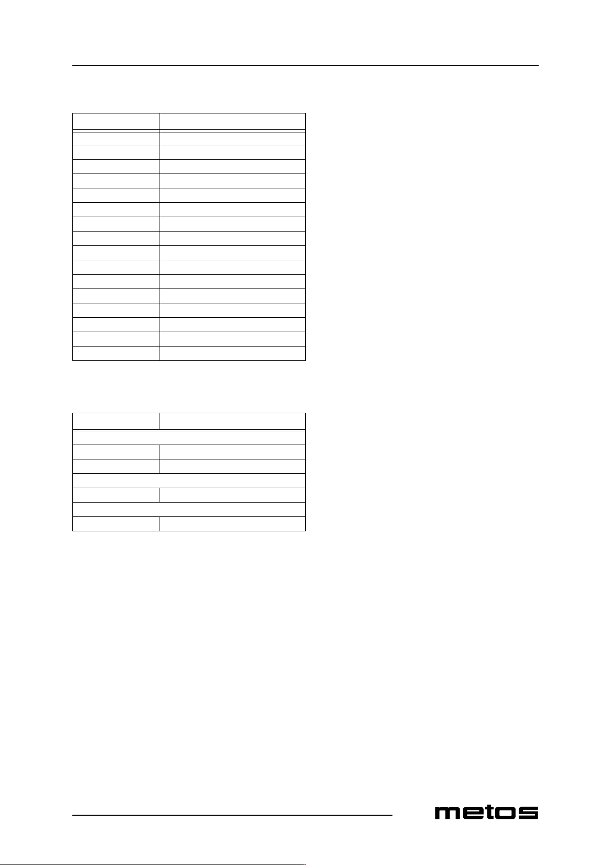
Voltage code Voltage
A 3/N/PE∼400/230V 50Hz B ∼250V 16A 50Hz C 3/N/PE∼380/220V 50Hz D3/PE∼200V 50-60Hz F2/PE 220−240V 50Hz G 3/N/PE∼415/240V 50Hz H3/PE∼230V 50Hz I3/PE∼220V 60Hz J3/PE∼380 50Hz K3/PE∼400V 50Hz L3/PE∼415V 50Hz M3/PE∼440V 60Hz N3/PE∼460V 60Hz O3/PE∼480V 60Hz P 1/N/PE~220-240V 50Hz R 2/PE~220-230V 60Hz
4.12.2000 Rev. 2.2
8.1 Voltage codes
8.2 Product codes
Product code Full name
Model codes E ELECTRICALLY HEATED S STEAM HEATED Type codes 151 151E Accessory codes FS40 FS40
! applies only to codes not listed
29
Page 30
Spare parts
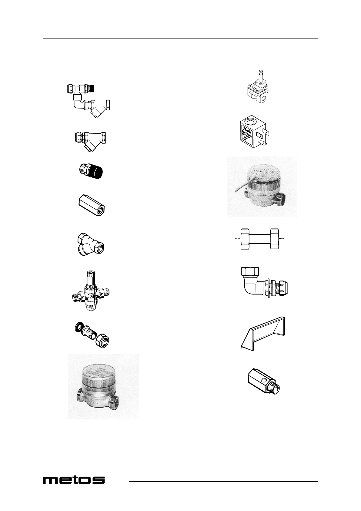
10
20
30
40
4.12.2000 Rev. 2.2
80
90
100
50
60
70
75
110
120
130
140
30
Page 31
4.12.2000 Rev. 2.2
Spare parts
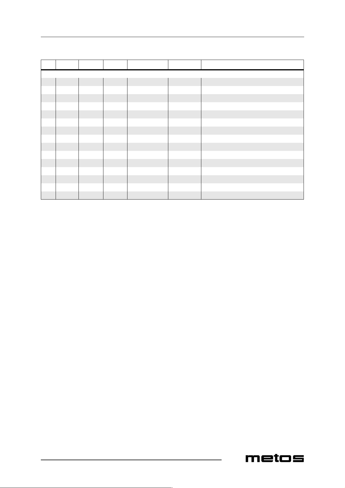
ID Code Model Type Accessory Voltage Description
MODULE:Water connections 10 5320206 Cold water connection 20 5320205 Hot water connection 30 5320002 Vacuum valve 40 5320225 Non return valve 1/ 2" 50 5320224 Filter 1/2" 60 5320220 Reducing valve 70 5320180 Coupling device 3/4"" x 1/2" for re ducing valve 75 5315611 Water meter 80 5320248 Solenoid valve 24V 90 5320249 Coil 24V 100 5315612 Water meter with impulse generator BV1 110 5320179 Connecting pipe d=15,m 3/4" x 3/4", L=60mm 120 43744.01 Angle connection 3/4" x 1/2" 130 5320129 Valve hood 140 5315593 Ball valve 1/2"
31
Page 32
Spare parts
4.12.2000 Rev. 2.2
150
160
170
180
190
200
32
Page 33
4.12.2000 Rev. 2.2
Spare parts
ID Code Model Type Accessory Voltage Description
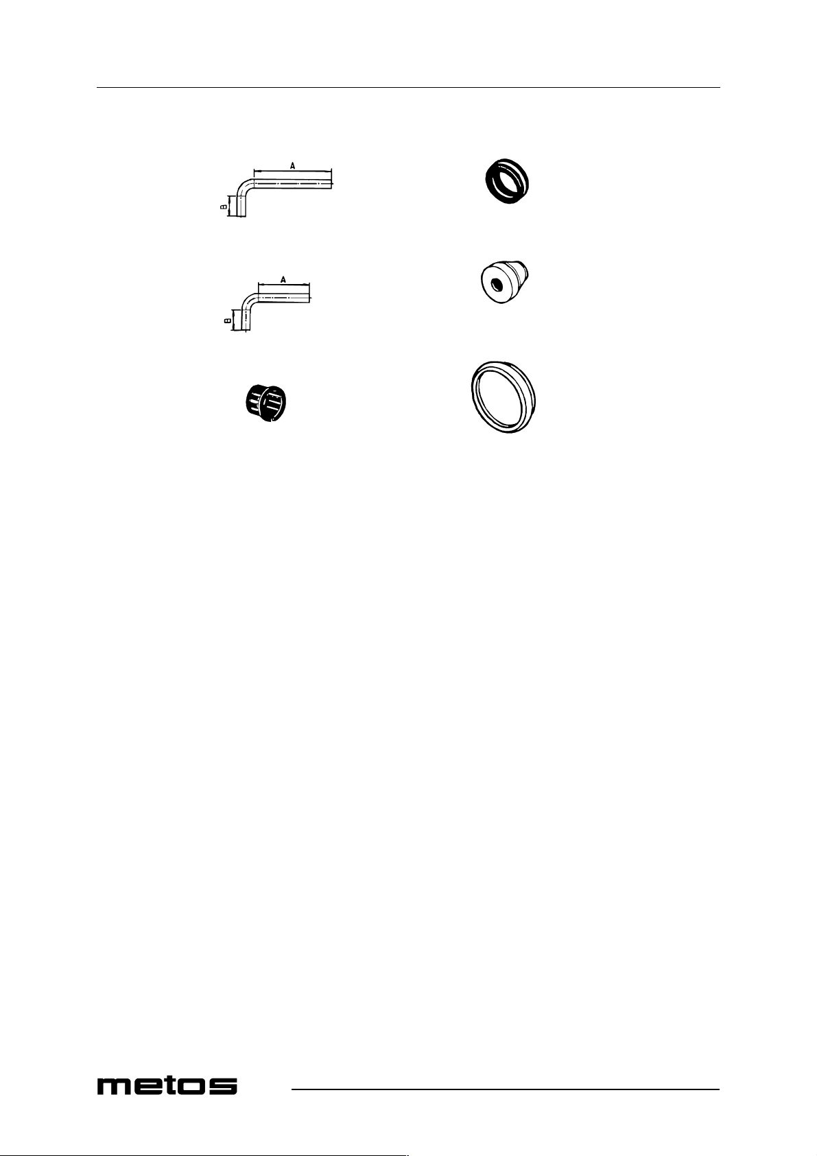
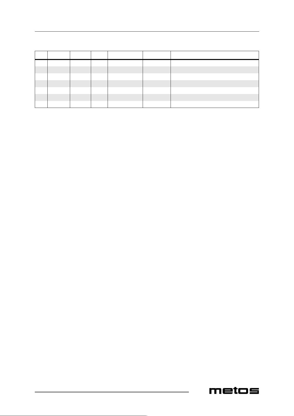
150 5320186 Pipe d=15mm. A=130mm B=35mm 160 5320185 Copper pipe d=15mm. A=90mm B=35mm 170 61701519 Conduit entry 1 5mm 180 719.1219 Conduit entry 15mm 190 51458029 Rubber sleeve TET 14-20 200 718.1050 Plastic plug d=62mm
33
Page 34
Spare parts
320
330
340
4.12.2000 Rev. 2.2
380
390
400
350
360
370
375
410
420
430
34
440
Page 35
4.12.2000 Rev. 2.2
Spare parts
ID Code Model Type Accessory Voltage Description
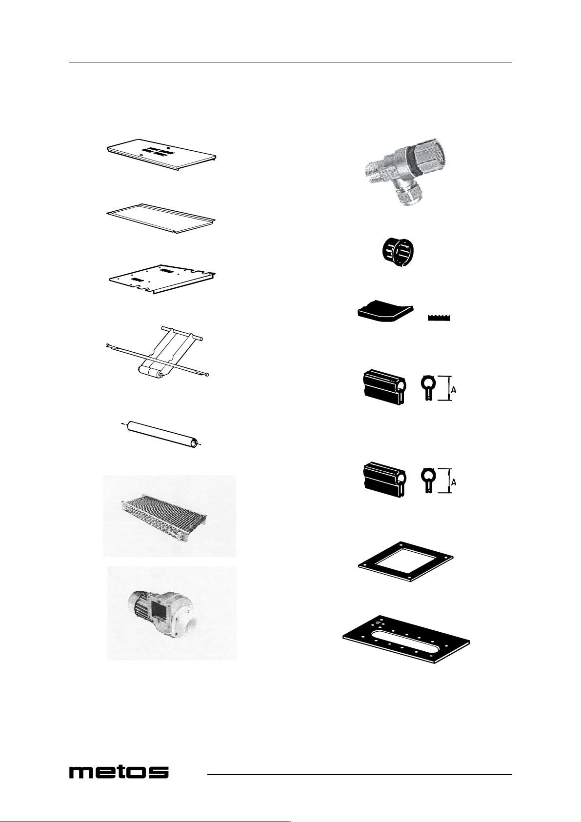
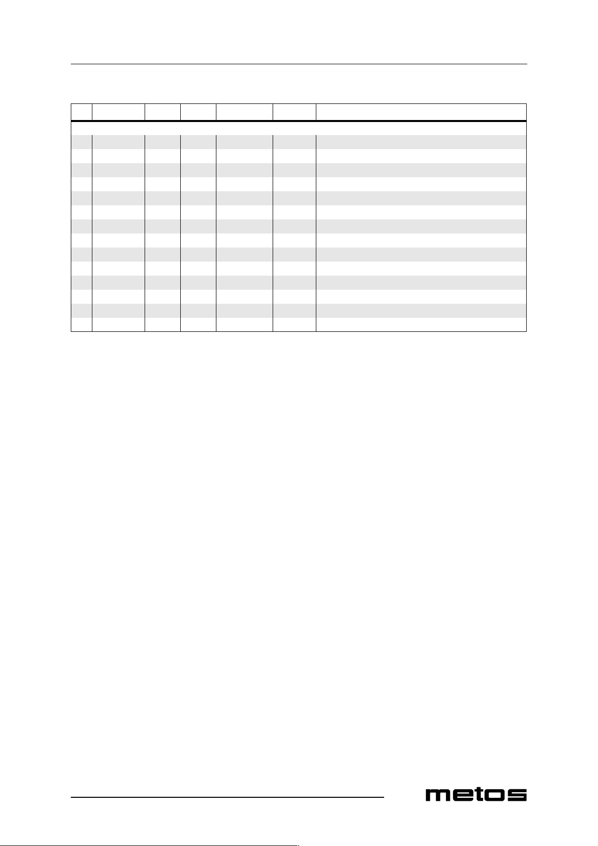
MODULE:Condensing battery, fan 320 5320121 Cover for condensing battery box 330 5320123 Cover for condensing battery 340 5320122 Cover for condensing fan 350 5320140 Lifting device 360 917.015010 Copper pipe d=15mm (State length whe n ordering) 370 5320255 Condensing batter y 375 5320141 A,H,M Cond ensing fan, complete 380 5315599 Safety valve 390 61701519 Conduit entry 15mm 400 5320241 Rubber moulding 15 x 8mm (State length when ordering) 410 5320242 Rubber moulding A=22mm (State length when ordering) 420 5320243 Rubber moulding A=15mm (State length when ordering) 430 5320188 Packing for condensing fan 440 5320187 Condensing battery gasket
35
Page 36
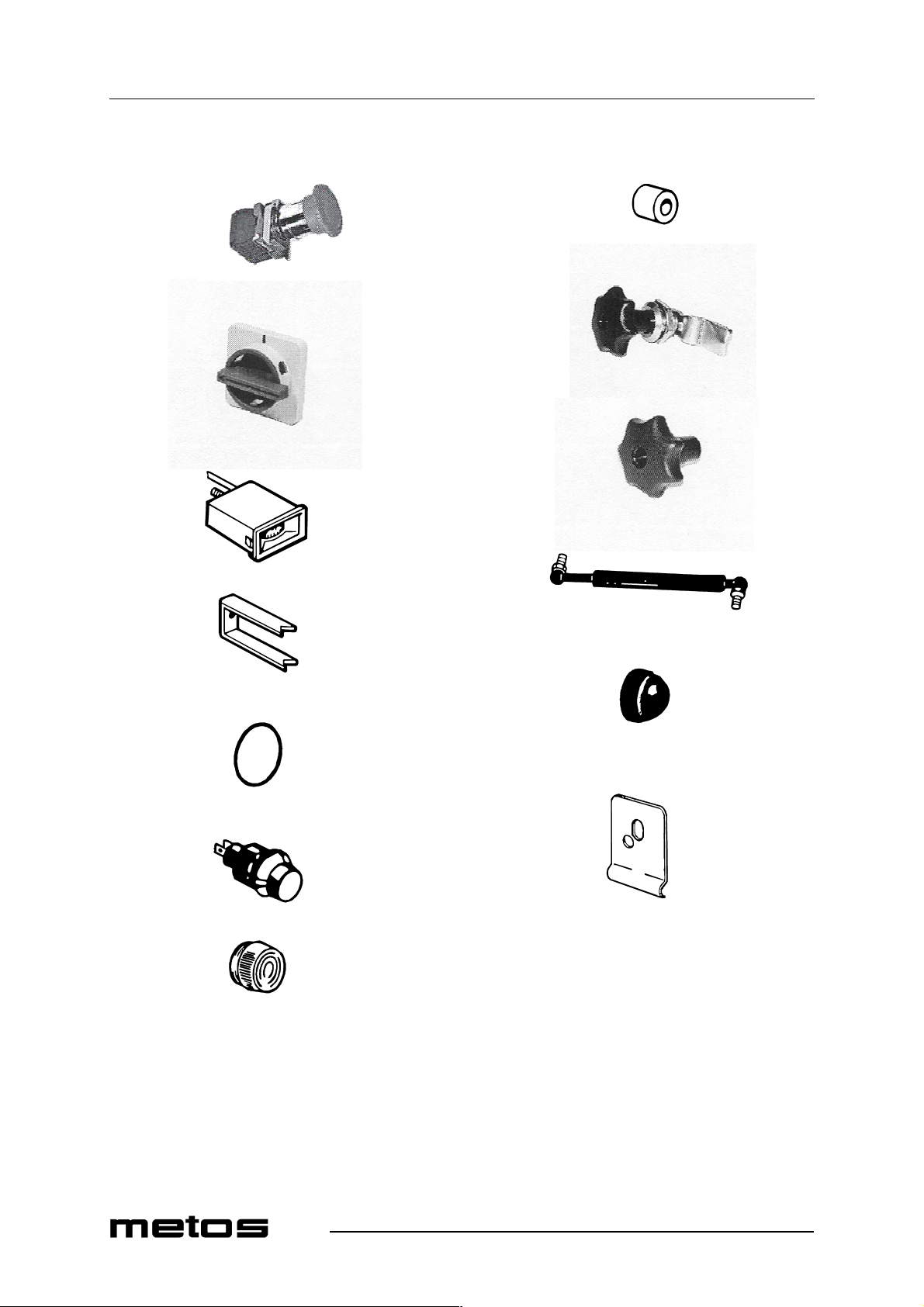
Spare parts
520
530
540
4.12.2000 Rev. 2.2
590
600
610
550
560
570
580
620
630
640
36
Page 37
4.12.2000 Rev. 2.2
Spare parts
ID Code Model Type Accessory Voltage Description
MODULE:Electric cubicle 520 5320328 Emergency stop 530 5320048 Knob 540 5315711 Thermometer 550 722.0104 Thermometer attachmen t 560 719.1031 O-ring 31,2 x 3,0 570 5315511 Pilot lamp complete, green 580 5315512 Lamp lens, green 590 5320196 Distance tube d=8mm L=7mm 600 5320250 Lock, complete 610 5320253 Locking knob 620 5320228 Gas spring 20 0N 630 5320238 Nut cover d=17mm 640 43743.32 Holder
37
Page 38
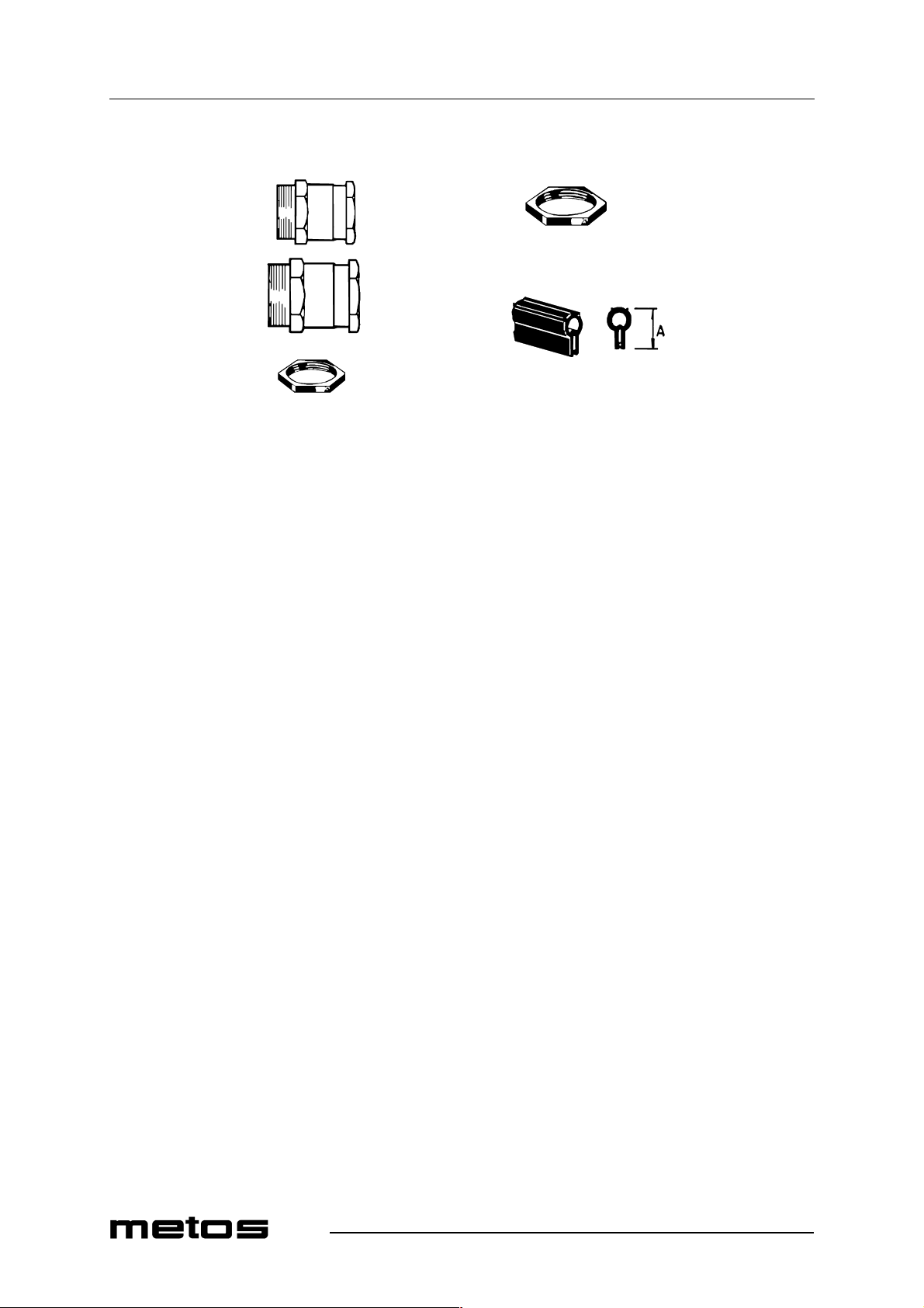
Spare parts
4.12.2000 Rev. 2.2
650
660
670
680
690
38
Page 39
4.12.2000 Rev. 2.2
Spare parts
ID Code Model Type Accessory Voltage Description
650 5320259 Cable screw cap 37mm (40 0V) 660 5320260 Cable screw cap 47mm (230V) 670 51465052 Lock nut 37mm (400V) 680 51465054 Lock nut 47mm (230V) 690 5320243 Rubber moulding A=15mm (State length when
ordering)
39
Page 40
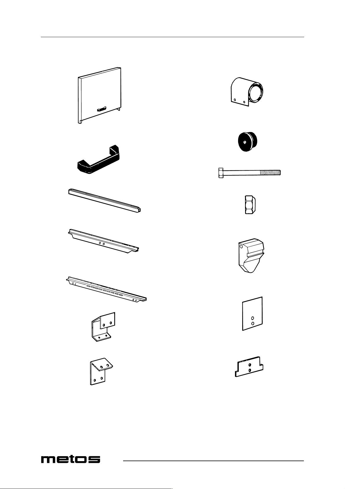
Spare parts
4.12.2000 Rev. 2.2
700
710
720
730
740
750
790
795
800
810
820
760
765
770
780
830
840
850
40
Page 41
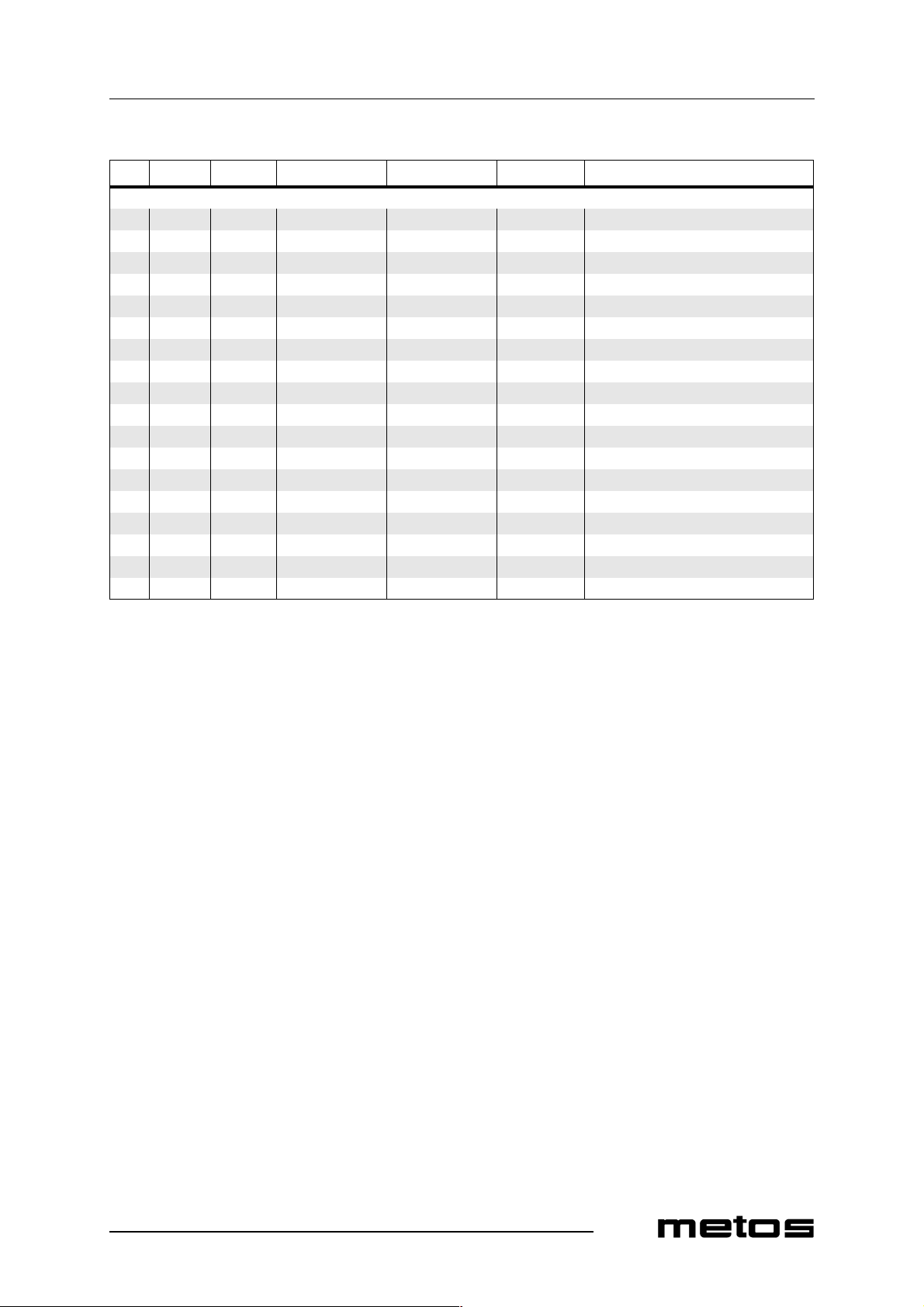
4.12.2000 Rev. 2.2
Spare parts
ID Code Model Type Accessory Voltage Description
MODULE:Doors, curtains 700 5320091 Door, complete Wid th 400mm 710 5320092 Door, complete Width 600mm 720 5320093 Door, complete Wid th 900mm 730 5320237 Handle 740 5320157 Sliding border L=618mm (plastic) 750 5320169 Fastening border for door (400mm) 760 5320165 Fastening border for door (600mm) 765 5320166 Fastening border for door (900mm) 770 5320167 Spring bracket 780 5320168 Washer 790 5320229 Spring 30N 795 5315515 Spring 47N 800 5320329 Roller for door spring d=40mm (plastic) 810 700.0144 Screw M8 x 70 820 700.1405 Locking nut M8 830 5320127 Holder 840 5320184 Plate spring 45 x 60 850 5320189 Stop lug
41
Page 42
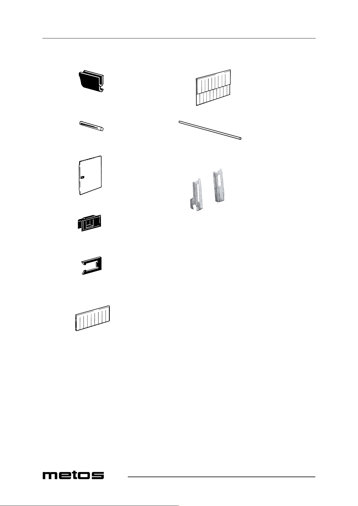
Spare parts
860
4.12.2000 Rev. 2.2
930
870
880
890
900
940
950
910
42
Page 43
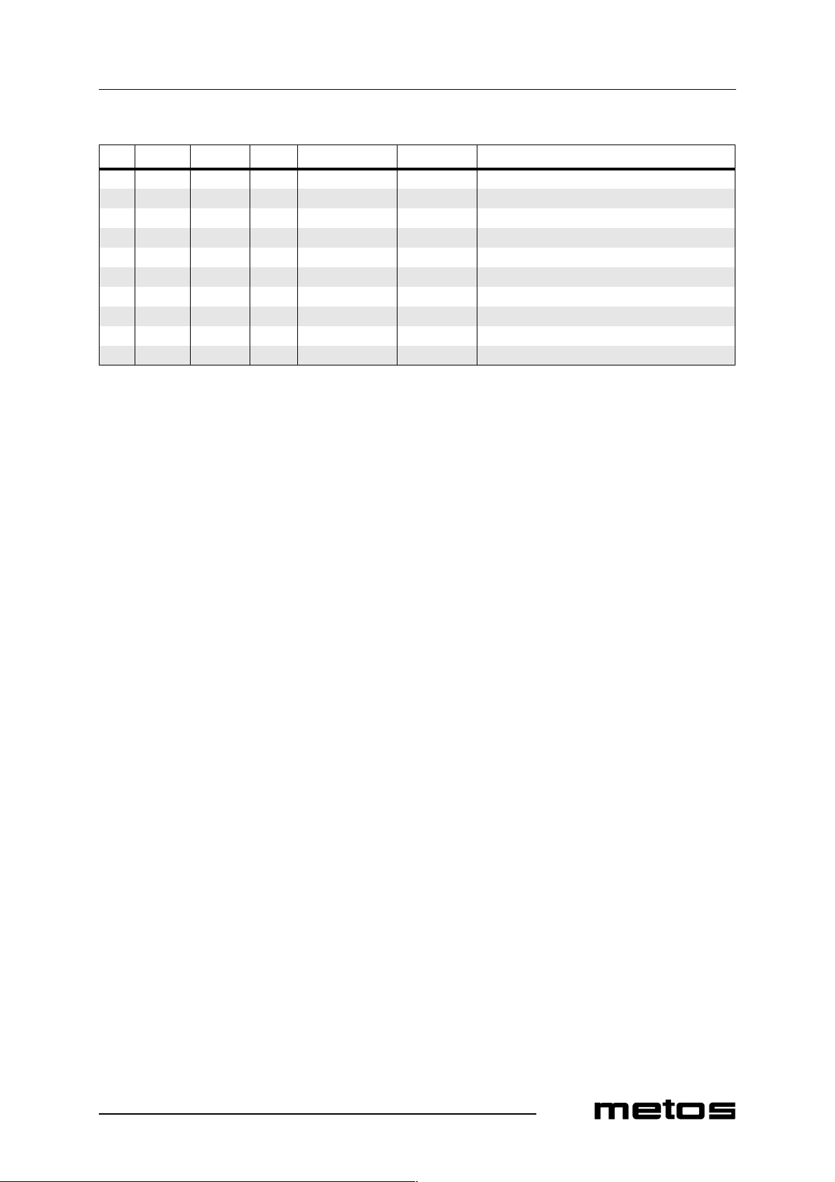
4.12.2000 Rev. 2.2
Spare parts
ID Code Model Type Accessory Voltage Description
860 5320244 Rubber moulding (State length when ordering) 870 5315353 Magnet 6 x 50 880 5320115 Lower final rinse door (complete) 890 5320251 Sliding lock 900 5320252 Locating clip 910 5315224 Curtain (short) 930 5315226 Curtain (long) 940 5315286 Curtain rod 950 5320330 Curtain suspension
43
Page 44
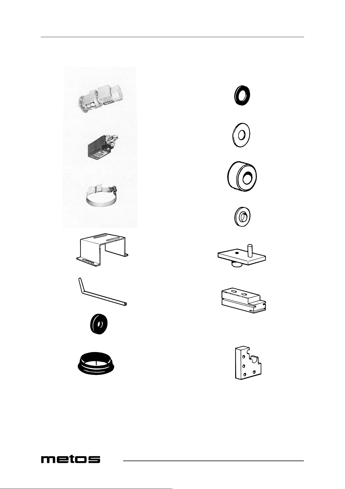
Spare parts
4.12.2000 Rev. 2.2
960
970
980
990
1030
1040
1050
1060
1070
1000
1010
1020
1080
1090
44
Page 45
4.12.2000 Rev. 2.2
Spare parts
ID Code Model Type Accessory Voltage Description
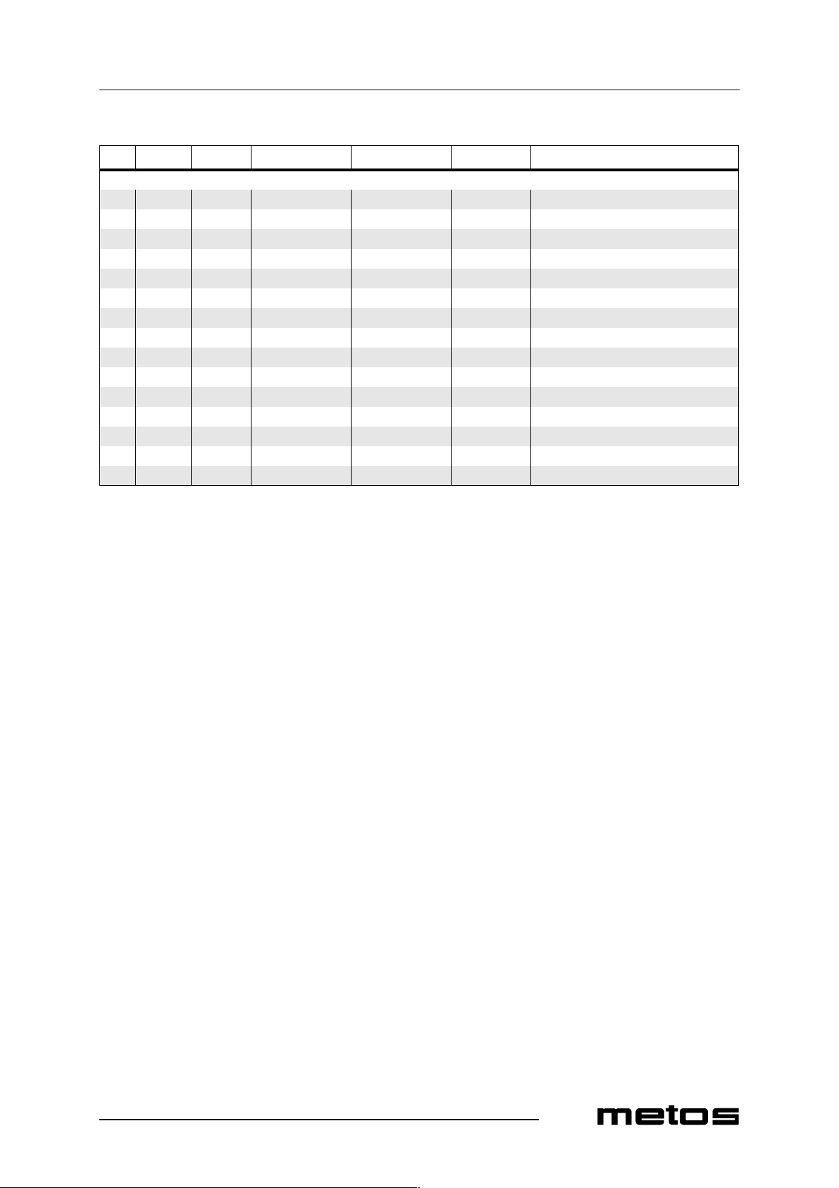
MODULE:Transporter 960 5320043 A,H,M Feedin g mo to r 960 806.1910 A,H,M Feeding motor 970 5320051 Limit position 980 5320132 Attachment for overload breaker 990 36028.31 Attachment 1000 5320272 Draining pipe d=10mm 1010 5315693 Distance rubber d=10 x 25 1020 5315685 V-ring V50S 1030 5315121 Packing d=25 x 40 1040 5315167 Protection washer d=25 x 65 1050 5315111 Feed roller d=20 x 45 1060 5315571 Grommet d=8 x 16 (plastic) 1070 5315207 Feed crank 1080 5320153 Slide block 1090 5320107 Slide block
45
Page 46
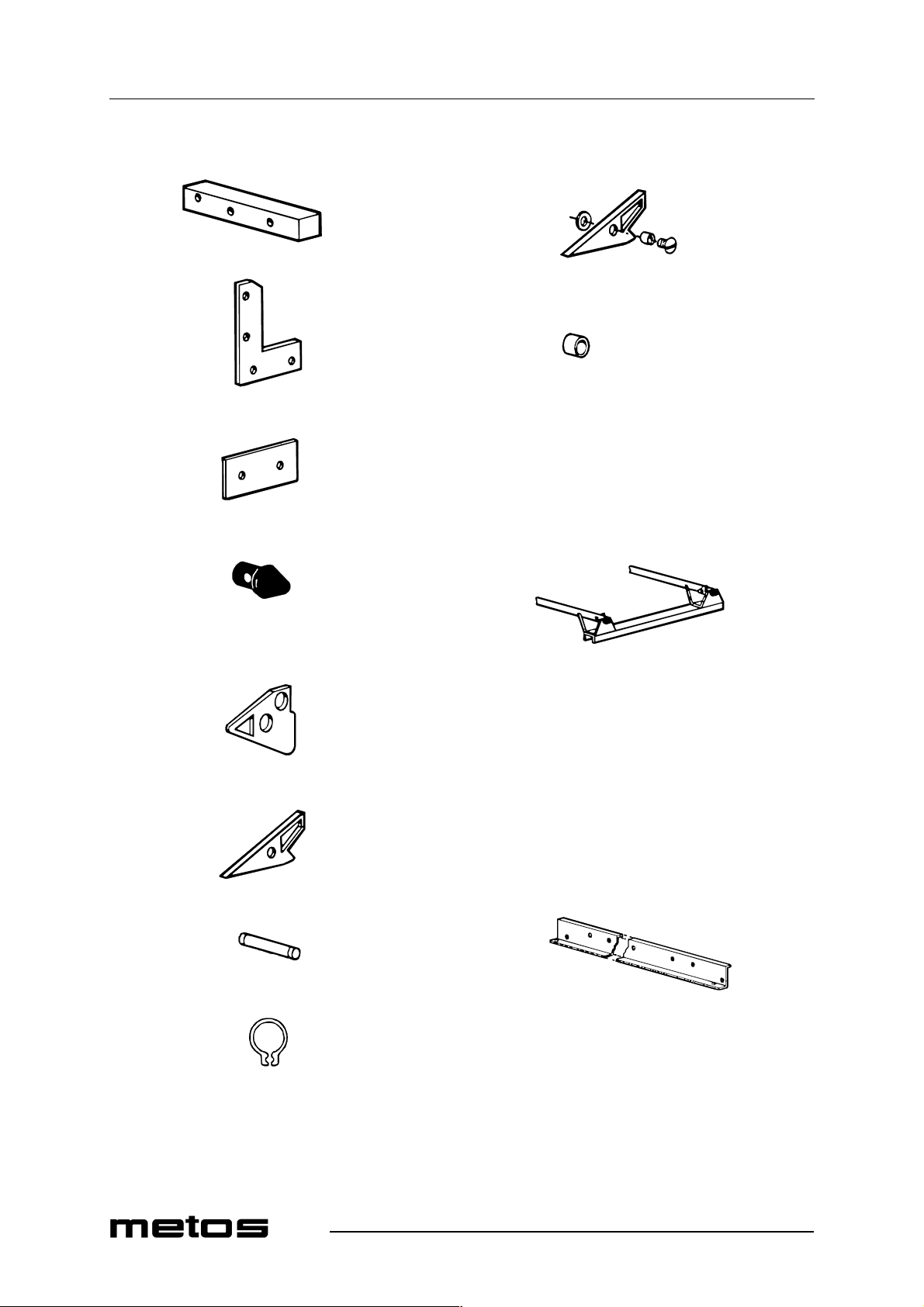
Spare parts
1100
4.12.2000 Rev. 2.2
1180
1110
1120
1130
1140
1190
1200
1210
1220
1230
1150
1160
1170
46
1240
1250
1260
1270
Page 47
4.12.2000 Rev. 2.2
Spare parts
ID Code Model Type Accessory Voltage Description
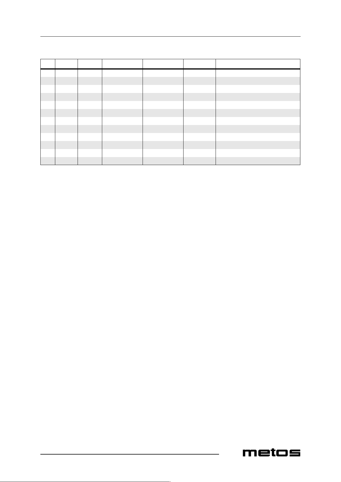
1100 5320156 Distance block 1110 5320177 Washer 1120 5320176 Washer 76 x 41 1130 5320154 End plug 1140 5320156 Clutch 1150 5320158 Clutch 1160 5320331 Axle for clucth d=8mm, L=32mm 1170 5320195 Locking ring SGA 8 1180 5320159 Clutch, complete 1190 5320152 Bushing d=6 x 8 1200 5320094 Feeding cradle 1240 5320119 Feeding ba r
47
Page 48
Spare parts
4.12.2000 Rev. 2.2
1280
1360
1290
1300
1310
1320
1330
1340
1350
1370
1380
1390
48
Page 49
4.12.2000 Rev. 2.2
Spare parts
ID Code Model Type Accessory Voltage Description
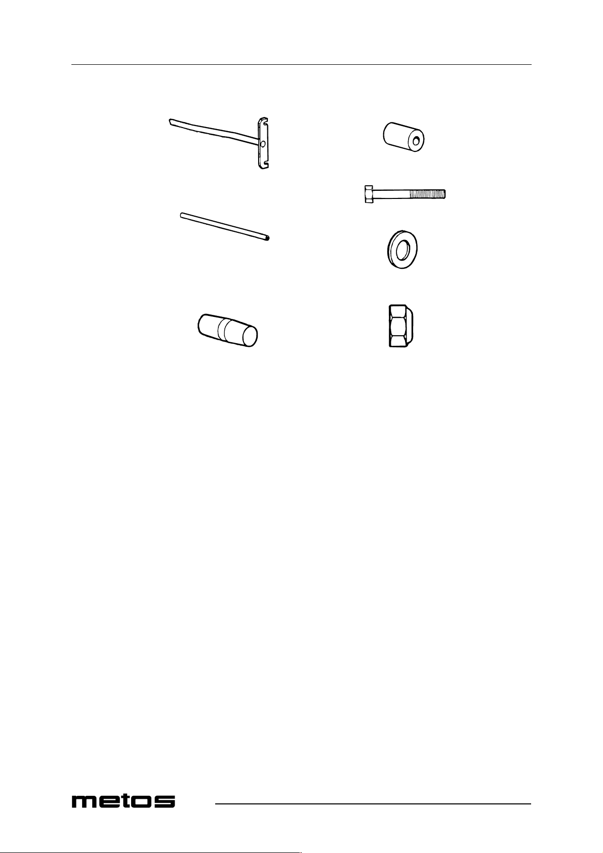
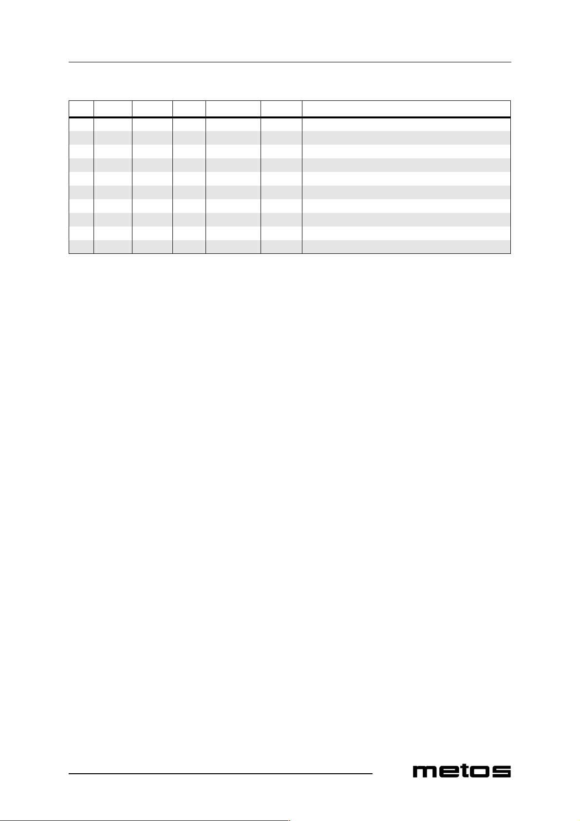
1280 36483.01 Connector pipe 1290 5320136 Guide pipe L=908mm 1330 43357.35 T -60 Guide pipe L= 605mm 1340 43357.36 T-90 Guide pipe L=905mm 1350 5320332 Connecting plug for guide pipe d=15mm, L=46mm, plastic 1360 5320175 Distance sleeve d=16 1370 700.0120 Screw M6 x 40 1380 700.1205 Washer d=6,4 x 18mm 1390 700.1404 Locking nut M6
49
Page 50
Spare parts
4.12.2000 Rev. 2.2
1400
1410
1420
1430
1440
1470
1480
1490
1500
1510
1450
1460
1520
1530
50
Page 51
4.12.2000 Rev. 2.2
Spare parts
ID Code Model Type Accessory Voltage Description
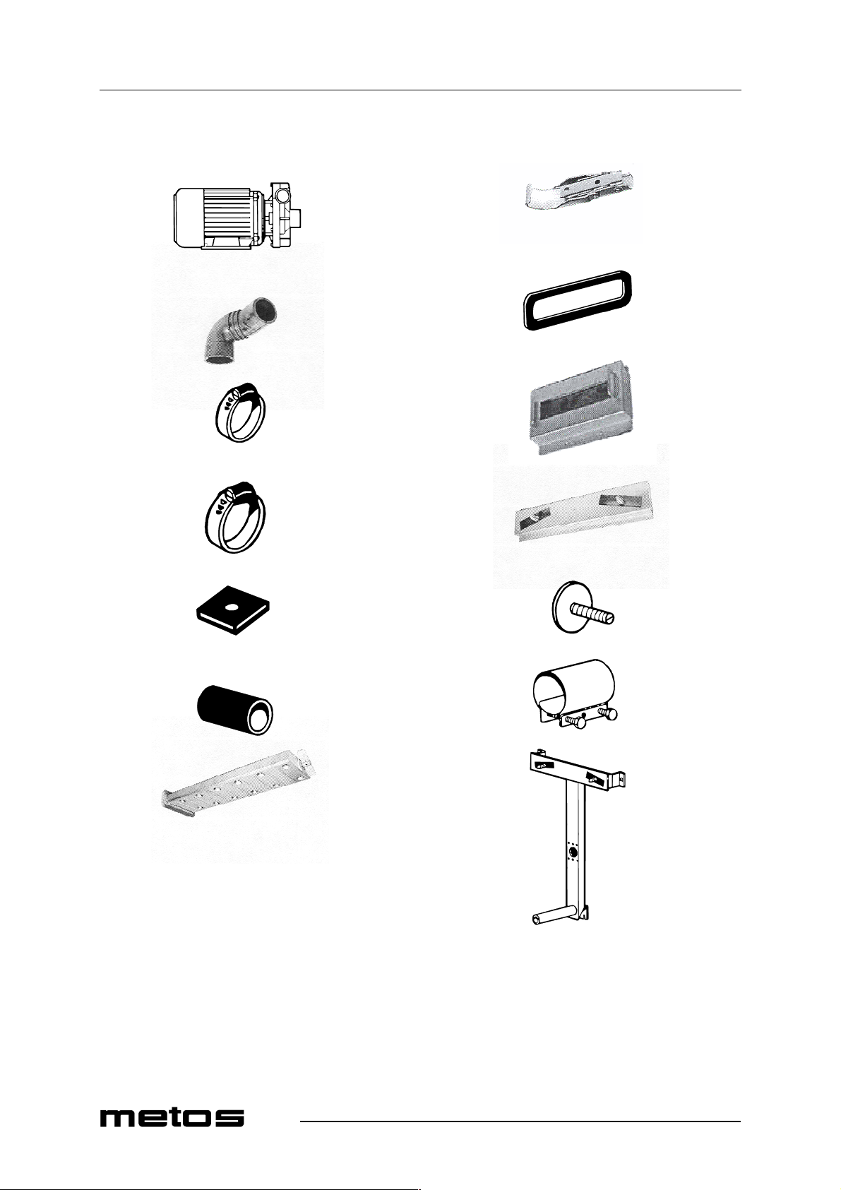
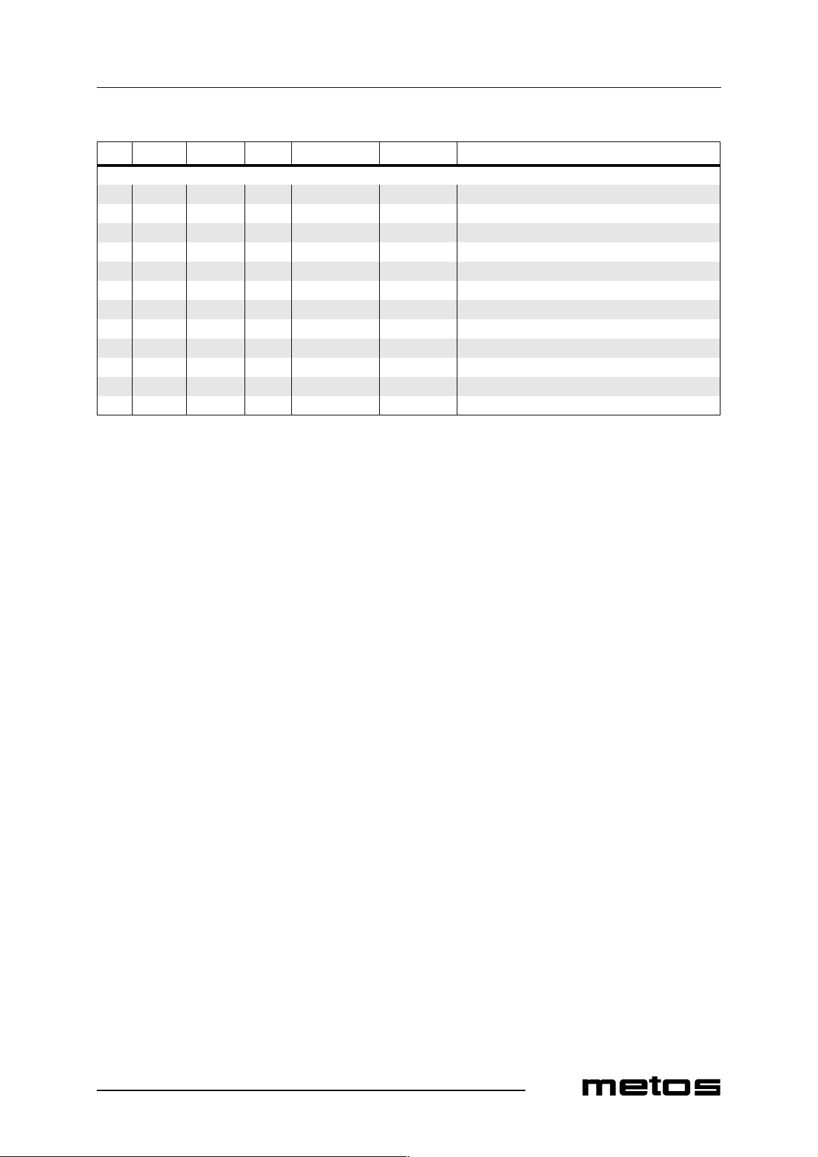
MODULE:Pre-wash 1400 5320294 A,H,M Pump FIR 1226 1410 5320134 Pump connection 1420 5320026 Hose clamp 40-60 1430 5320016 Hose clamp 50-70 1440 5320246 Rubber foot 30 x 30 x3 1450 5320235 Radiator hose d=50mm (State length when ordering) 1460 5320100 Rinse arm, complete 1470 5320333 Eccentric lock 1480 36374.31 Packing for rinse arm 1510 5320174 Adjusting plate 1520 5320233 Hose clamp 50/65 1530 5320090 Main pipe
51
Page 52
Spare parts
4.12.2000 Rev. 2.2
1540
1550
1560
1570
1610
1620
1630
1640
1580
1590
1600
1650
1660
1670
52
Page 53
4.12.2000 Rev. 2.2
Spare parts
ID Code Model Type Accessory Voltage Description
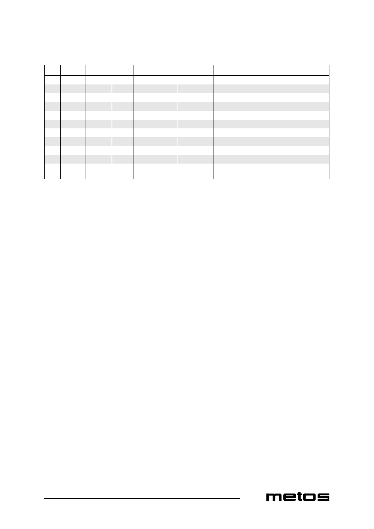
1540 5320133 Strainer
1580 5320181 Holder for magnet and field break switch
1590 5315033 Pump strainer
1600 5320112 Level pipe
1610 5315699 Level pipe seal
1620 5315802 Screw cap for thermostat
1630 5315687 PVC-hose d=5 x 8 (State le ngth when ordering)
1640 43743.31 Attachment for temperature sensor
1650 5320143 Foot L=245mm
1660 5315677 Plastic foot
1670 5320164 Main pipe for intermediate rinse d=15mm,
L=550mm
53
Page 54
Spare parts
4.12.2000 Rev. 2.2
1680
1720
1690
1700
1705
1710
1730
1740
54
Page 55
4.12.2000 Rev. 2.2
Spare parts
ID Code Model Type Accessory Voltage Description
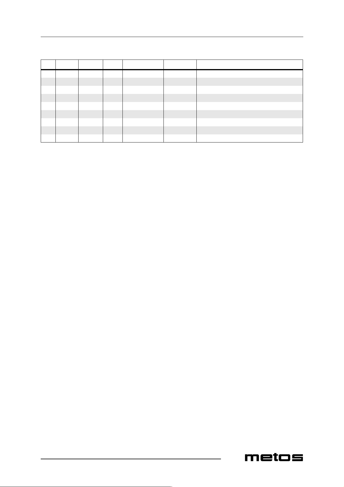
1680 5320171 Rinse pipe for intermediate rinse, complete 1690 5315643 Nozzle 1/16 1700 5315363 Photocell, receiver B62 1705 5315365 Photocell, transmitter B61 1710 5320334 Cable screw cap 18,6mm 1720 5320335 Lock nut 18,6mm 1730 5320336 Packing d=19 x 27mm 1740 5320337 Washer d=11 x 16mm
55
Page 56
Spare parts
1750
1760
1770
1780
4.12.2000 Rev. 2.2
1830
1840
1850
1860
1790
1800
1810
1820
1870
1880
1890
56
Page 57
4.12.2000 Rev. 2.2
Spare parts
ID Code Model Type Accessory Voltage Description
MODULE:Chemical wash 1750 5320294 A,H,M Pump FIR 1226 1760 5320134 Pump connection 1770 5320026 Hose clamp 40-60 1780 5320016 Hose clamp 50-70 1790 5320246 Rubber foot 30 x 30 x3 1800 5320235 Radiator hose d=50mm (State length when ordering) 1810 5320100 Rinse arm, complete 1820 5320333 Eccentric lock 1830 36374.31 Gasket for wash arm 1840 5320111 Lower rinsing ramp 1850 5320174 Adjusting plate 1860 5320233 Hose clamp 50/65 1870 5320090 Main pipe 1880 5320133 Strainer 1890 5320332 Plug for detergent connection d=15mm, L=46mm, plastic
57
Page 58
Spare parts
4.12.2000 Rev. 2.2
1900
1910
1920
1930
1970
1980
1990
2000
1940
1950
1960
2010
2020
2030
2040
58
Page 59
4.12.2000 Rev. 2.2
Spare parts
ID Code Model Type Accessory Voltage Description
1910 5320130 Strainer plate 1920 5320131 Strainer plate 1930 5315033 Pump strainer 1940 5320112 Level pipe 1950 5320113 Outlet sealing 1960 5315699 Level pipe seal 1970 5315802 Screw cap for thermostat 1980 5315687 PVC-hose d=5 x 8 (State le ngth when orderin g) 1990 5320151 Attachment for temperature sensor 2000 5320181 Holder for magnet and field break switch 2010 5320193 Plastic washer d=10,5 x 18 2020 5320041 Conductivity cell 2030 5315199 Element 9kW 2040 5315201 Element 12kW
59
Page 60
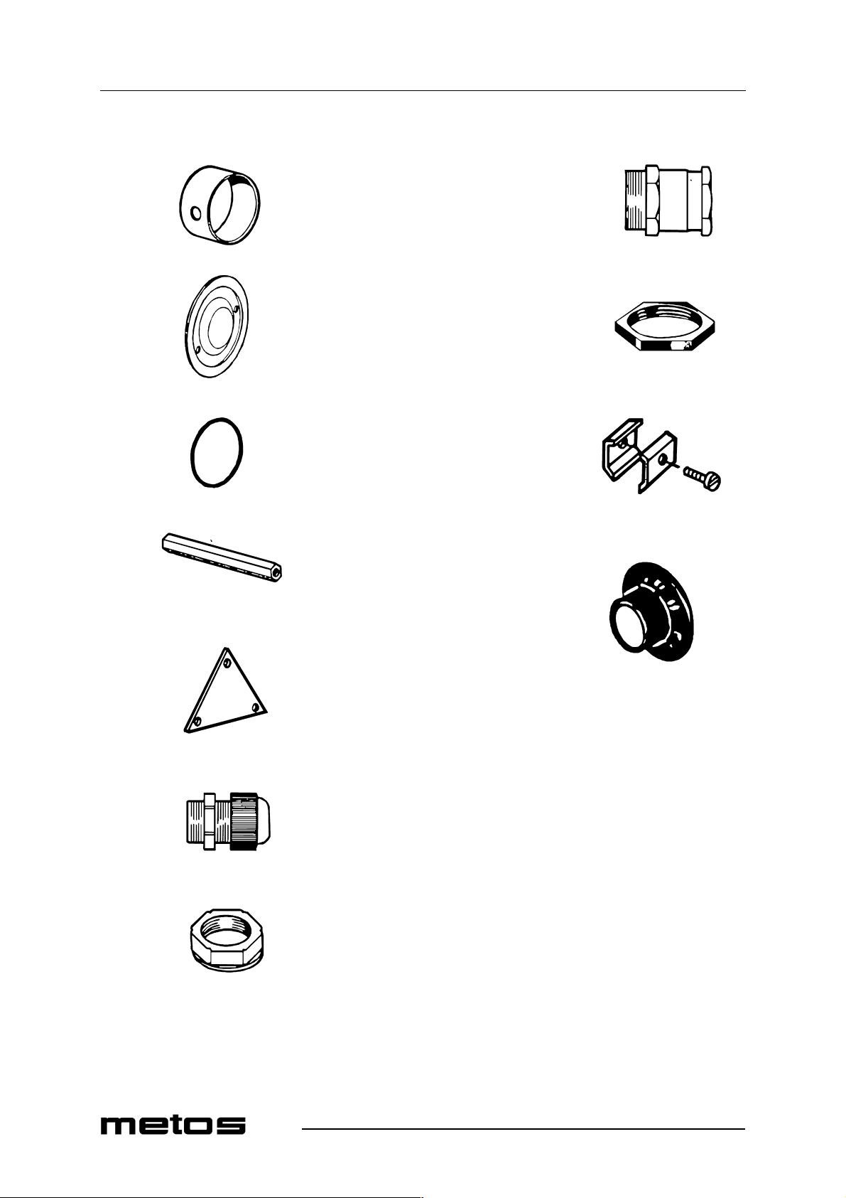
Spare parts
2050
2060
4.12.2000 Rev. 2.2
2130
2070
2080
2090
2100
2140
2150
2160
2110
2120
60
Page 61
4.12.2000 Rev. 2.2
Spare parts
ID Code Model Type Accessory Voltage Description
2050 5320274 Electric mantle 400V 2060 5320273 Electric mantle 230V 2070 5320144 Electric mantle cover 2080 5315689 O-ring d=90 x 4,0 2090 5320275 Distance nut 2100 5320276 Copp er clamp 2110 5320257 A,M Cable screw cap 18,6mm (400V) plastic 2120 5320262 A,M Lock nut 18,6mm (plastic) 2130 5320258 H Cable screw cap 22,5mm (230V) 2140 5320261 H Lock nut 22,5mm 2150 5320269 Thermostat attachment 2160 734.0303 Thermostat knob
61
Page 62
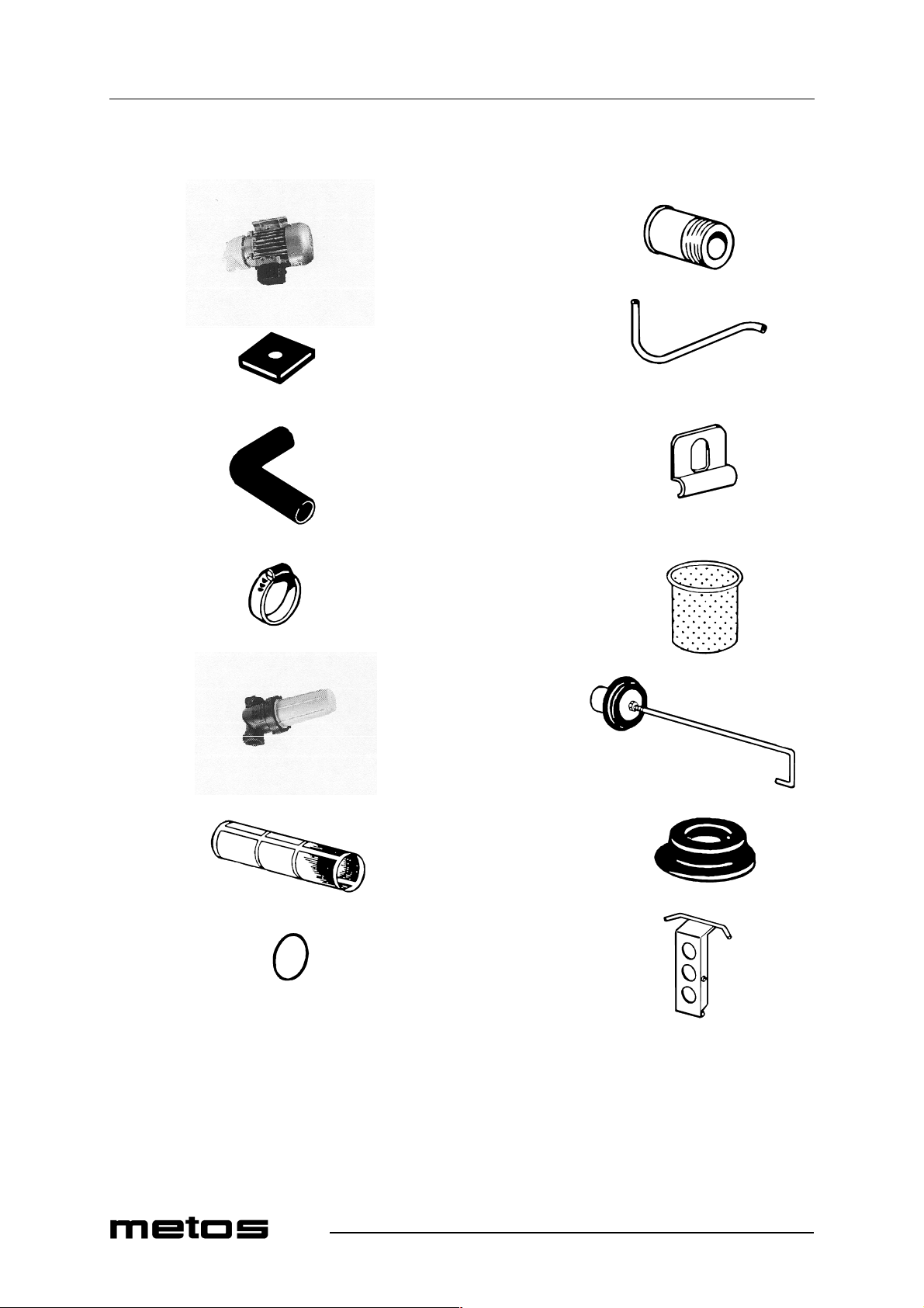
Spare parts
2170
4.12.2000 Rev. 2.2
2240
2180
2190
2200
2210
2250
2260
2270
2280
2220
2230
62
2290
2300
Page 63
4.12.2000 Rev. 2.2
Spare parts
ID Code Model Type Accessory Voltage Description
MODULE:Final rinse, emptying 2170 5320042 A,H,M Pump FIR M0247 2180 5320246 Rubber foot 30 x 30 x3 2190 5315697 Rubber bend 60 x 120 x 25 2200 5320020 Hose clamp 20-32 2210 5315606 Filter, complete 2220 5315610 Filter strainer 2230 5315609 O-ring to filter 2240 5320150 Muff d=25 L=34mm (plasti c) 2250 5315687 PVC-hose d=5 x 8 (State le ngth when orderin g) 2260 5320181 Holder for magnet and field break swit c h 2270 5315208 Strainer 2280 5315204 Outlet sealing 2290 5315699 Level pipe seal 2300 5320120 Final rinse breaker
63
Page 64
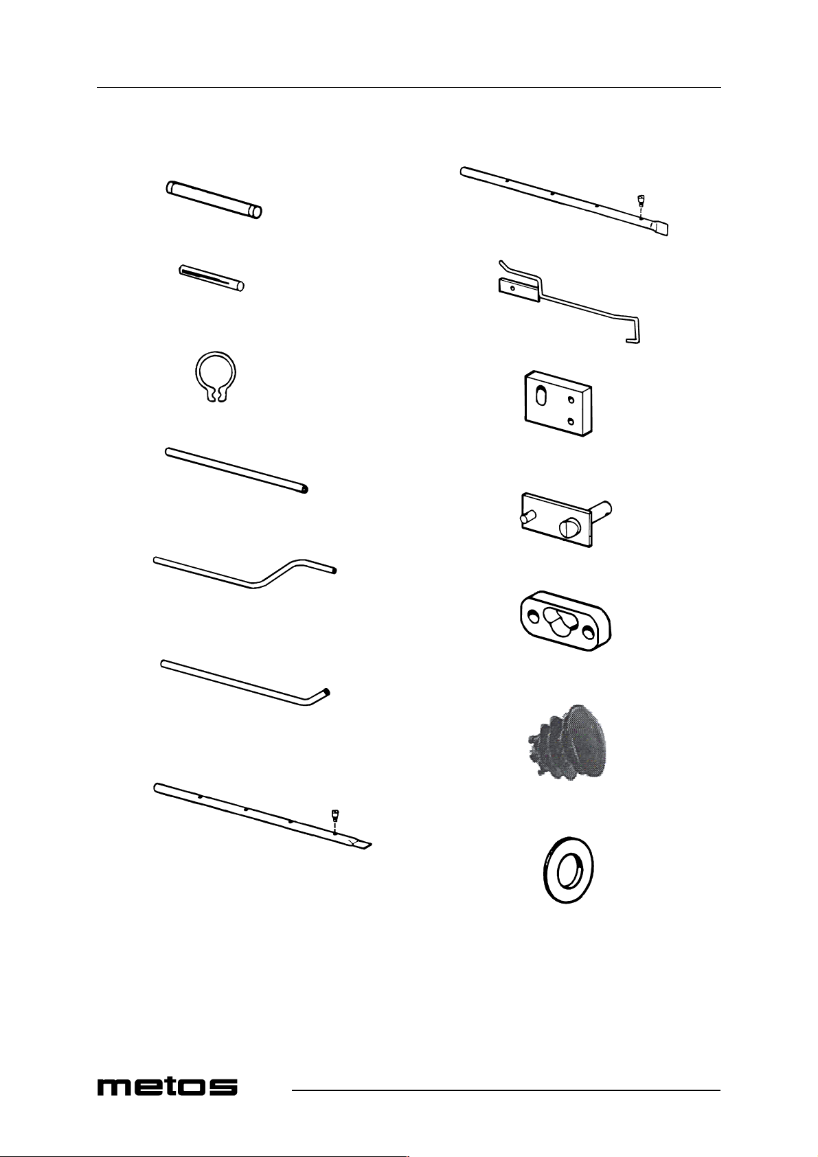
Spare parts
2310
2320
2330
2340
4.12.2000 Rev. 2.2
2390
2400
2410
2420
2350
2360
2370
2380
2430
2440
2450
2460
64
Page 65
4.12.2000 Rev. 2.2
Spare parts
ID Code Model Type Accessory Voltage Description
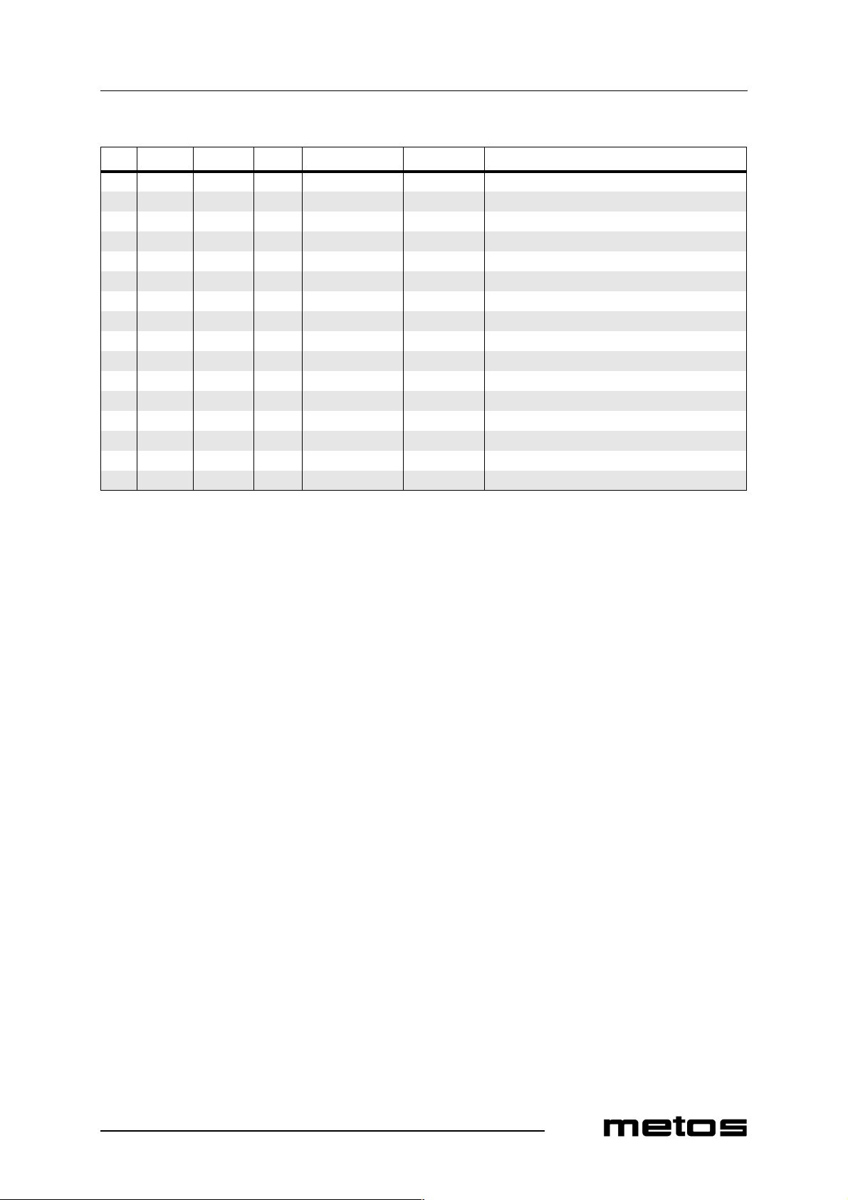
2310 5320182 Axle to final rinse breaker d=8mm L=64mm 2320 5315353 Magnet 6 x 50 2330 5320195 Locking ring SGA 8 2340 5320183 Main pipe, final rinse d=15mm L=579mm 2350 5320149 Main pipe, re-circulating final rinse d=15mm 2360 5320173 Filler pipe d=15mm 2370 5320171 Rinse pipe, re-circulating final rinse (complete) 2380 5315643 Nozzle 2390 5320172 Rinse pipe, final rinse (compl ete) 2400 5315650 Nozzle 2410 5320126 Emptying bar 2420 5320160 Support for emptying bar 2430 5320125 Knob for emptying 2440 5320162 Bearing for lifting shaft 2450 5320338 Plastic plug for lifting shaft d=15mm 2460 5320192 Washer d=17 x 30
65
Page 66
Spare parts
4.12.2000 Rev. 2.2
2480
2490
2470
2500
2510
66
Page 67
4.12.2000 Rev. 2.2
Spare parts
ID Code Model Type Accessory Voltage Description
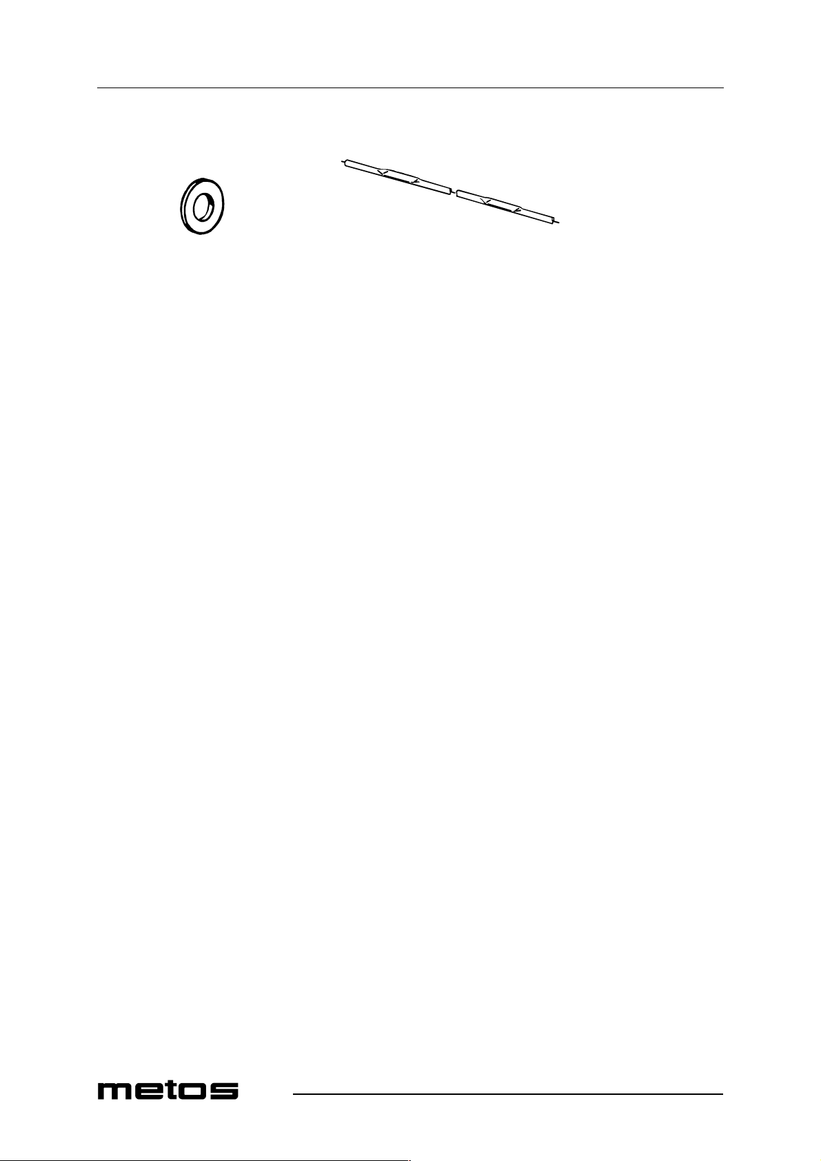
2470 5320191 Washer d=13 x 24 2480 5320108 Lifting axle for level pipe and outlet sealings
67
Page 68
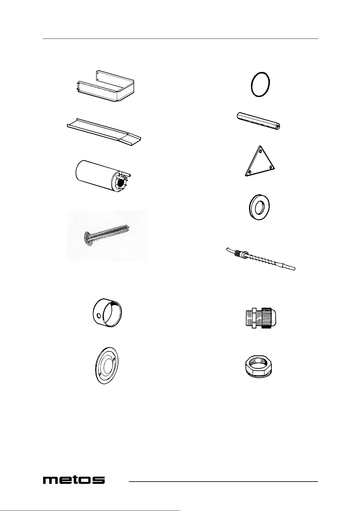
Spare parts
4.12.2000 Rev. 2.2
2520
2530
2540
2550
2560
2570
2620
2630
2640
2650
2660
2580
2590
2600
2610
2670
2680
2690
2700
68
Page 69
4.12.2000 Rev. 2.2
Spare parts
ID Code Model Type Accessory Voltage Description
MODULE:Booster heater 2520 5320117 Booster heater holder 2530 5320128 Emptying plate 2540 5315015 Container, standard version 2550 5320267 Container, electronic version 2560 5320101 A,H Element 9 kW with fusible cut-out 2570 5315199 A,H Element 9 kW with out fusible cut-out 2580 5315201 A,H Element 12 kW without fusible cut-out 2590 5320274 A,H Electric mantle 400 V 2600 5320273 H Electric mantle 230 V 2610 5320144 Electric mantle cover 2620 5315689 O-ring d=90 x 4,0 2630 5320275 Distance nut 2640 5320276 Copper clamp 2650 5320194 Packing 8 x 14 x 1,5 2660 5315465 Temperature sensor, complete 2670 5320146 Screw 2680 5320145 Spring 2690 5320257 Cable screw cap 18,6mm (400V), plastic 2700 5320262 A,M Lock nut 18,6mm (plastic)
69
Page 70
Spare parts
4.12.2000 Rev. 2.2
2710
2720
2730
2740
2750
70
Page 71
4.12.2000 Rev. 2.2
Spare parts
ID Code Model Type Accessory Voltage Description
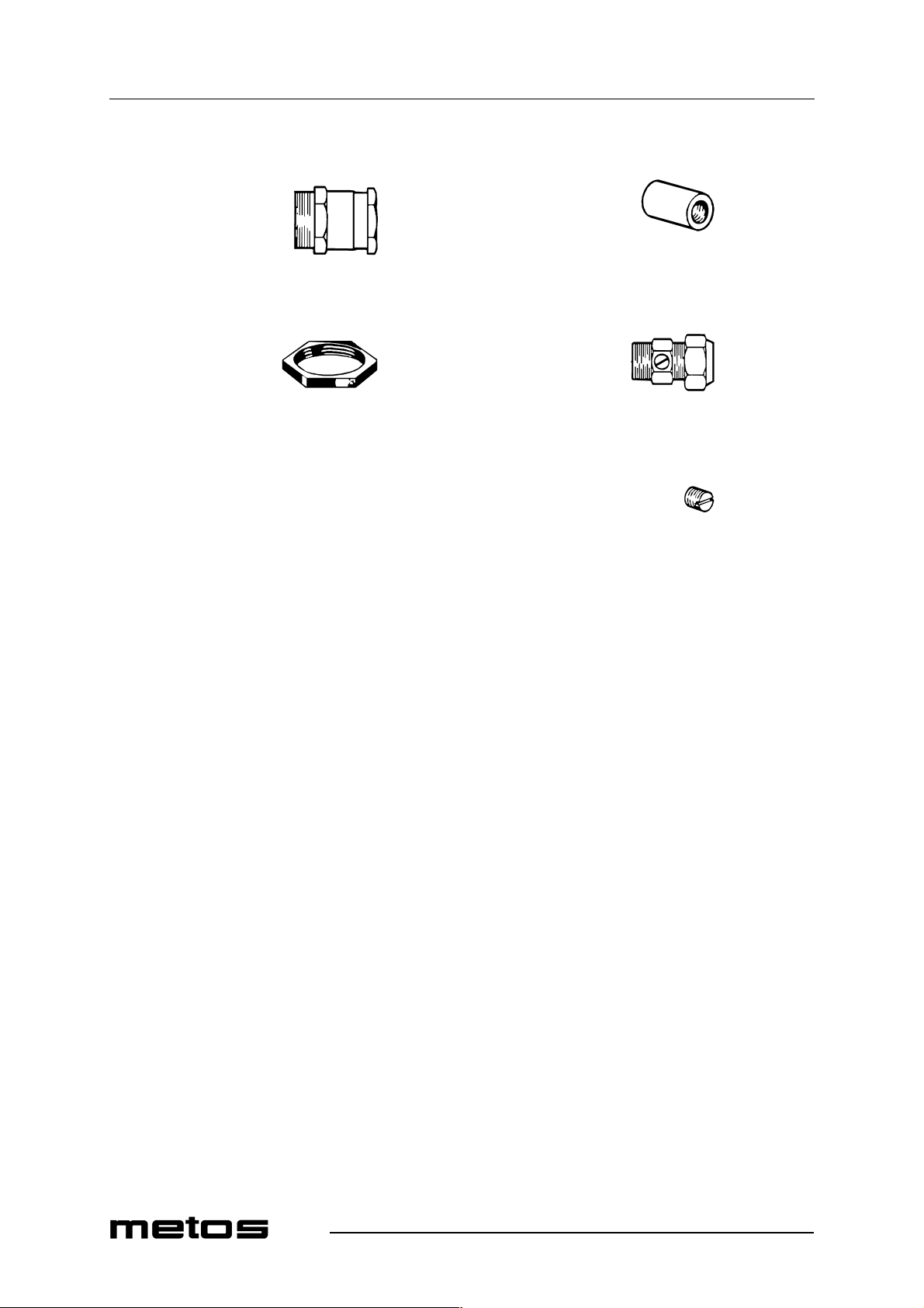
2710 5320258 A,M Cable screw cap 22,5mm (230V) 2720 5320261 Lock nut 22,5mm 2730 5315105 Thermostat attachment, d=15 L=21mm (brass) 2740 5315162 Connection coupling for detergent and drying agent 2750 5320271 Plug 1/8"
71
Page 72
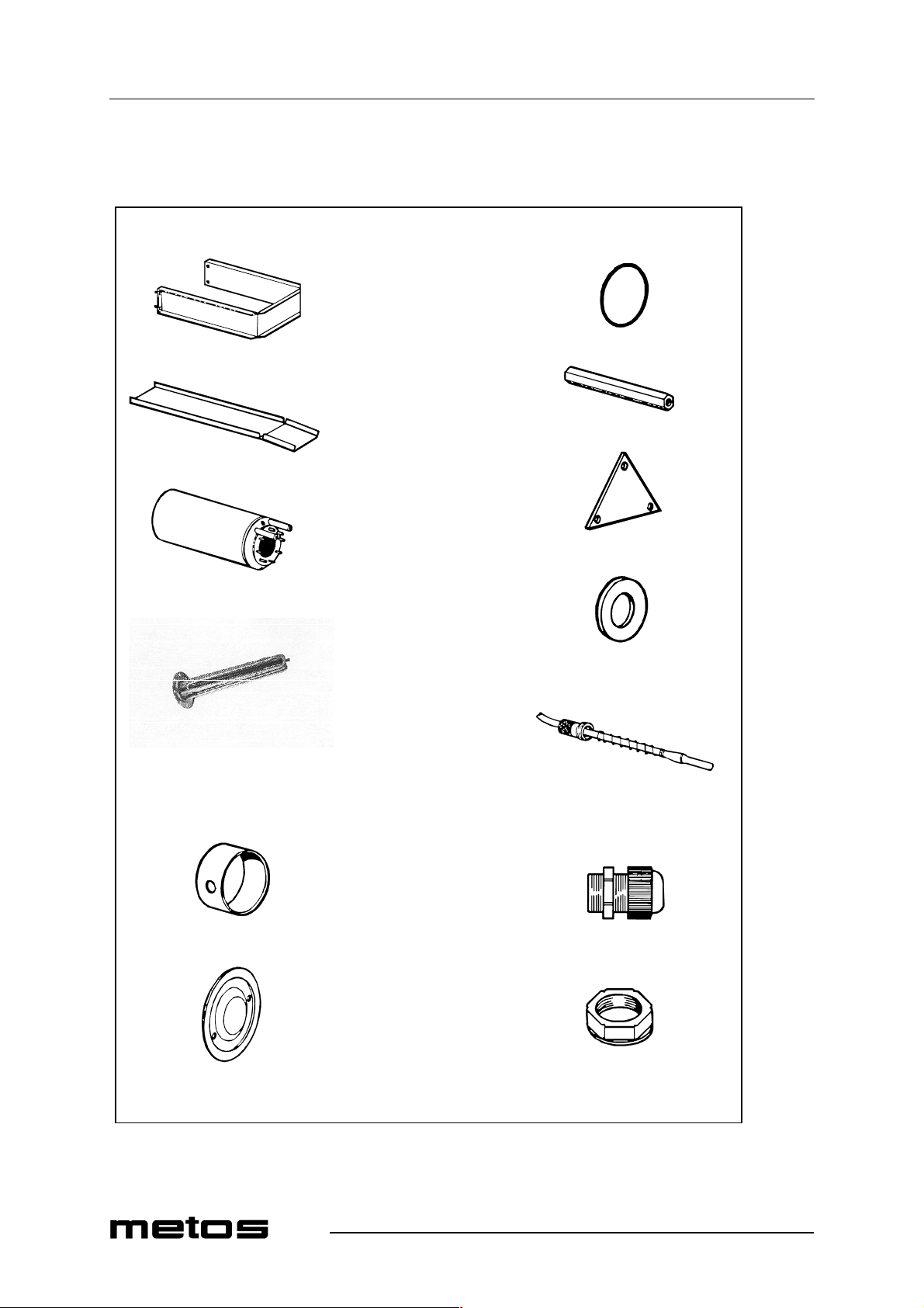
Spare parts
4.12.2000 Rev. 2.2
2755
72
Page 73
4.12.2000 Rev. 2.2
Spare parts
ID Code Model Type Accessory Voltage Description
MODULE:Sets of spare parts / Complete booster heater 2755 01163.21 A,H 9 kW standard version 2755 01163.14 A,H 9 kW electronic version 2755 01163.03 A,H 12 kW standard version 2755 011613.16 A,H 12 kW electronic version
73
Page 74
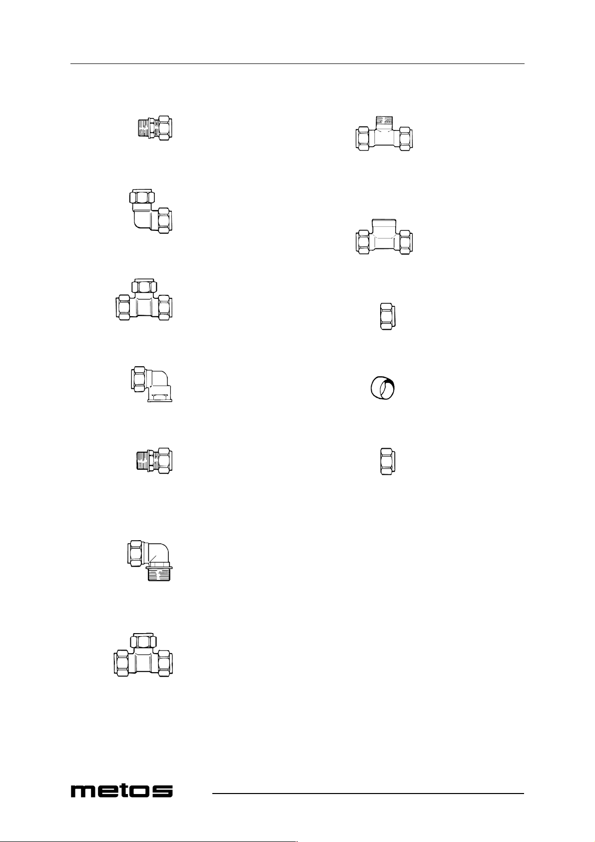
Spare parts
4.12.2000 Rev. 2.2
2760
2770
2780
2790
2830
2840
2850
2860
2800
2810
2820
2870
74
Page 75
4.12.2000 Rev. 2.2
Spare parts
ID Code Model Type Accessory Voltage Description
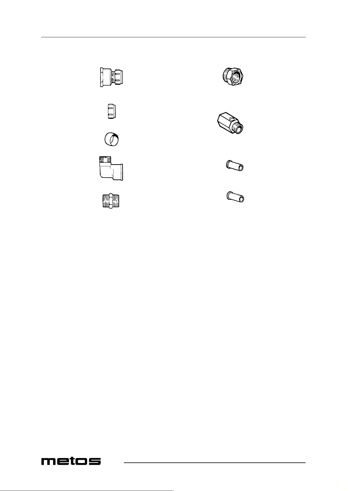
MODULE:Couplings, pipe details 2760 5315581 Coupling COMISA 1/2" x 15mm 2770 5320209 Coupling COMIS A 15 x 15mm 2780 5320000 Coupling COMISA 15 X 15 x 15mm 2790 5315585 Coupling COMISA, 15mm x 1/2" 2800 5315581 Coupling COMISA, 15mm x 1/2" chromium-plated 2810 5315583 Coupling COMISA 1/ 2" x 15mm chromium-pl a ted 2820 5320212 Coupling COMISA 15 X 15 x 15mm chromium-plated 2830 5320213 Coupling COMISA 15 x 1/2" x 15mm chromium-plated 2840 5320214 Coupling COMISA 15 x 1/2" x 15mm chromium-plated 2850 705.0315 Nut COMISA 15mm 2860 705.0420 Clamping sleeve COMISA 15mm 2870 705.0316 Nut COMISA, 15mm chromium-plated
75
Page 76
Spare parts
4.12.2000 Rev. 2.2
2880
2890
2900
2910
2920
2930
2940
2950
2960
76
Page 77
4.12.2000 Rev. 2.2
Spare parts
ID Code Model Type Accessory Voltage Description
2880 5320207 Coupling LK 303 15mm x 3/4" 2890 5320198 Nut LK 63 15mm 2900 5320200 Clamping sleeve LK 65 15mm 2910 5320217 Coupling 1/2" x 1/2" 2920 5320216 Nipple 1/2" 2930 5320215 Bushing 3/4" x 1/2" 2940 5315593 Ball valve 1/2" 2950 705.0104 Support sleeve F PL 720 12 x 1,0mm 2960 705.0102 Support sleeve FPL 720 15 x 1,0mm
77
Page 78
Spare parts
4.12.2000 Rev. 2.2
78
e53876e.cgm
Page 79
4.12.2000 Rev. 2.2
Spare parts
ID Code Model Type Accessory Voltage Description
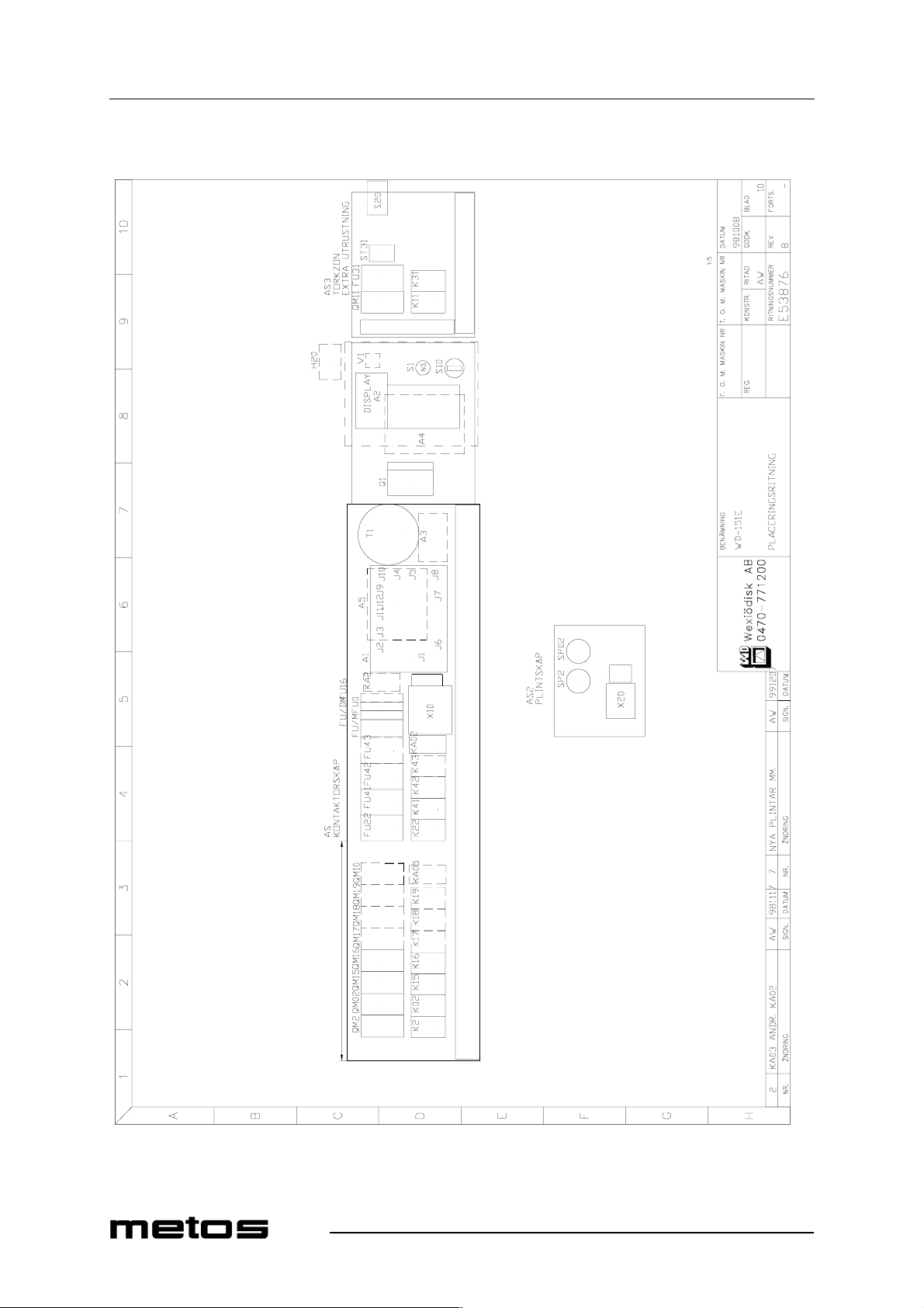
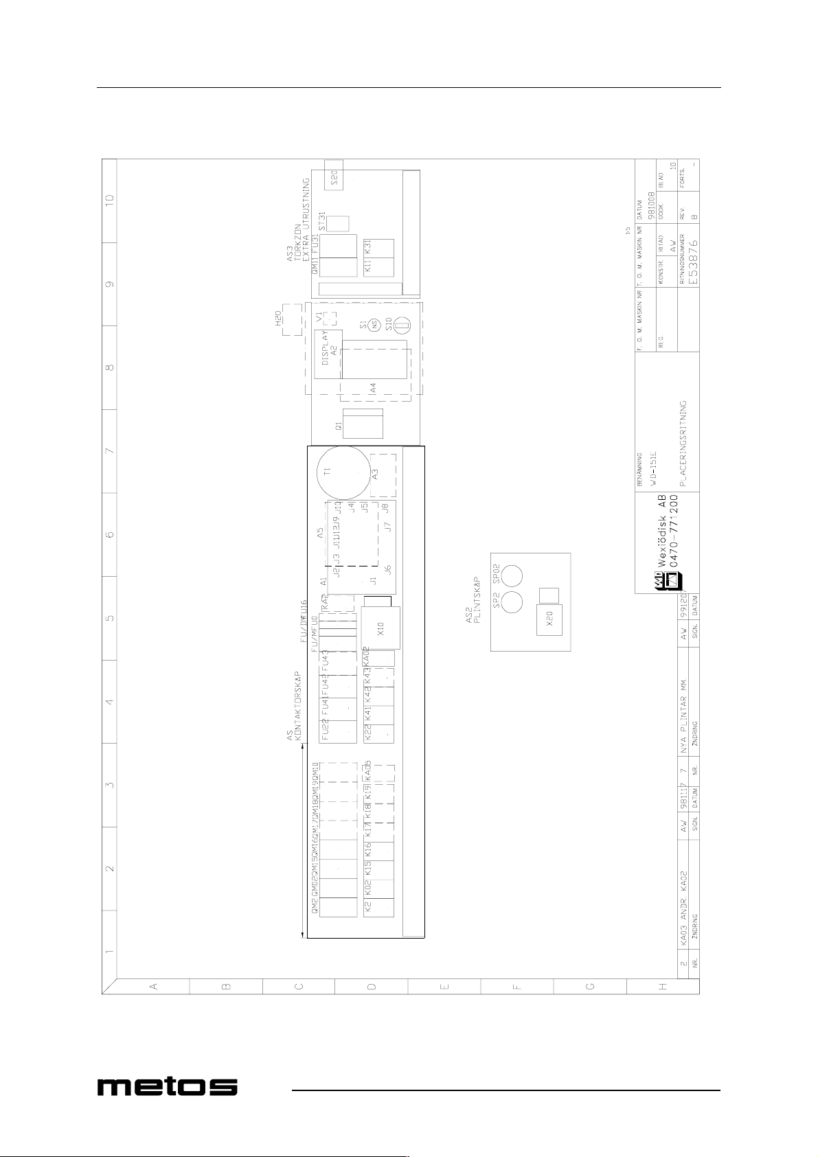
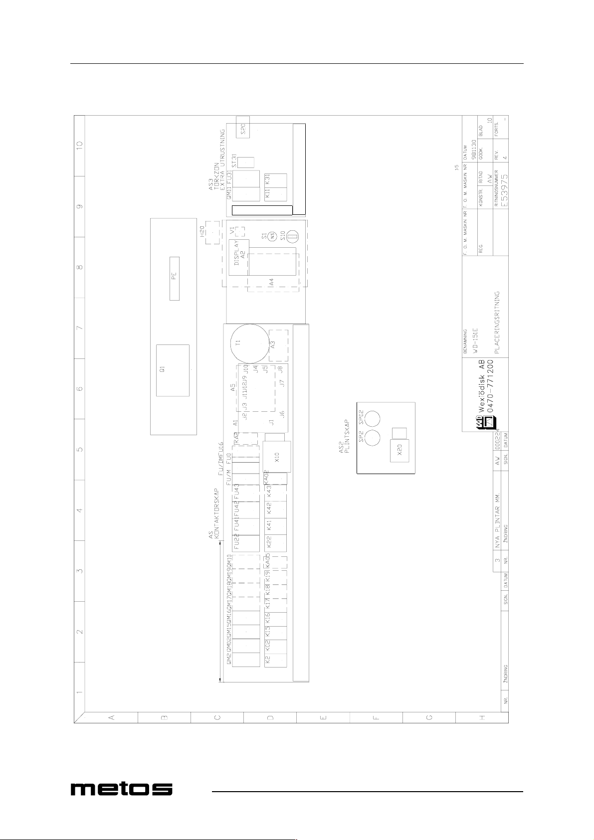
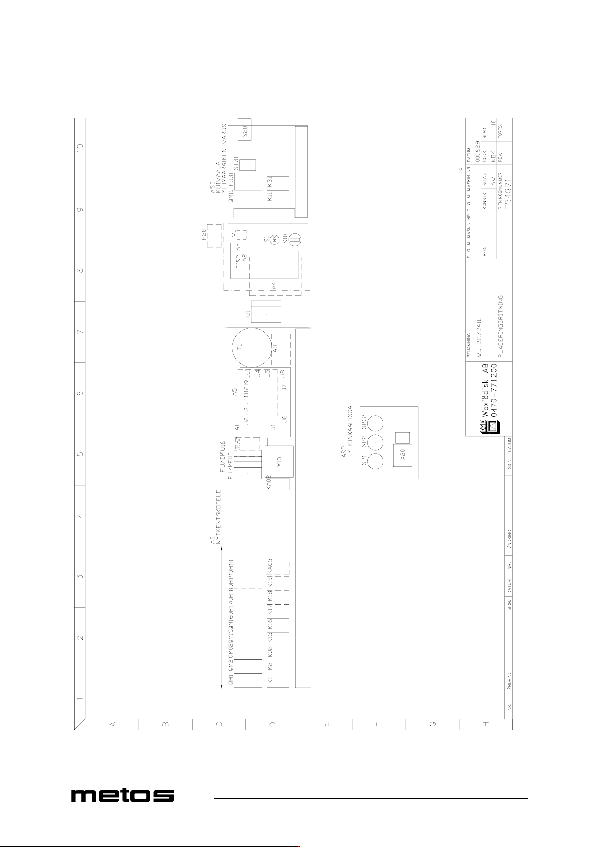
MODULE:Electric components [151E] A1 5315258 E A Circuit board
61007950 E A Eprom symb 61007960 E A Eprom text 61007970 E A Eprom symb 61008000 E A Eprom text
A2:1 5320283 E A Cable
5320080 E A Panel card symb A2:2 5320054 E A Panel card text A3 5315250 E A Relay card A4 5320078 E A Frequency exch.
5320061 E A Eprom A5 532 00 81 E A In te rface board C1 5315409 E A RC-unit C2 5315409 E A RC-unit FU/DM 5320075 E A Automatic fu se FU/M 5320077 E A Automatic fuse FU0 5320076 E A Automatic fuse FU16 5320076 E A Automatic fuse FU22 5315549 E A Automatic fuse FU41 5315549 E A Automatic fuse FU42 5315549 E A Automatic fuse FU43 64800325 E A Automatic fuse FV1 5320065 E A Varistor H20 55500242 E A Signal light K02 5315527 E A Contactor K1 5315527 E A Contactor K15 5315527 E A Contactor K16 5315527 E A Contactor K17 5315527 E A Contactor K172 5315527 E A Contactor K18 5315527 E A Contactor K19 5315527 E A Contactor K2 5315527 E A Contactor
5320287 E A Help cont. block K22 5315527 E A Contactor K41 5315527 E A Contactor K42 5315527 E A Contactor K43 5315527 E A Contactor
79
Page 80
Spare parts
4.12.2000 Rev. 2.2
80
e53876e.cgm
Page 81
4.12.2000 Rev. 2.2
Spare parts
ID Code Model Type Accessory Voltage Description
MODULE:Electric components [151E] KA02 5315244 E A Relay
5320046 E A Relay base KA05 5315244 E A Relay
5320046 E A Relay base KA2 5315244 E A Relay
5320046 E A Relay base KA20 5315244 E A Relay
5320046 E A Relay base Q1 5320047 E A Linebreaker
5320048 E A Knob
5320049 E A Axel
5320083 E A Extra conn. block QM02 5320070 E A Ther mal relay
5320073 E A Extra conn. block QM15 5320069 E A Ther mal relay
5320073 E A Extra conn. block QM16 5320070 E A Ther mal relay QM16 63113025 E A Thermal relay
5320073 E A Extra conn. block QM2 63113027 E A Thermal relay
5320073 E A Extra conn. block S1 5320328 E A Emergenc y stop S10 5315246 E A Switch S30 5315331 E A Switch T1 5320086 E A Transformer V1 ACS121805 E A Diod Z1 61075646 E A Ferrit core SP02 5315791 E A Pressure switch SP2 5315791 E A Pressure switch FU31 5315554 E A Automatic fuse K11 63723113 E A Contactor K31 63723113 E A Contactor QM10 63113027 E A Therm al relay
5320073 E A Extra conn. block QM11 5320071 E A Ther mal relay
63704900 E A Extra conn. block QM17 5320070 E A Ther mal relay
5320073 E A Extra conn. block QM172 5320070 E A Thermal relay
5320073 E A Extra conn. block QM18 5320070 E A Ther mal relay
5320073 E A Extra conn. block QM19 5320070 E A Ther mal relay
5320073 E A Extra conn. block
81
Page 82
4.12.2000 Rev. 2.2
Spare parts
ID Code Model Type Accessory Voltage Description
S20 5315331 E A Switch ST31 5315797 E A Thermostat
82
Page 83
Spare parts
4.12.2000 Rev. 2.2
83
Page 84
Spare parts
4.12.2000 Rev. 2.2
84
Page 85
4.12.2000 Rev. 2.2
Spare parts
ID Code Model Type Accessory Voltage Description
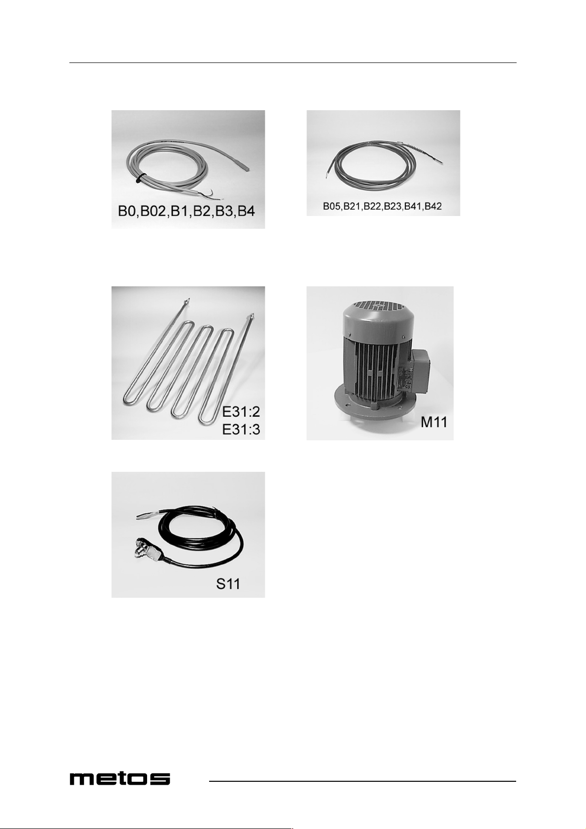
B0 5320290 E A Magnet switch B02 5320290 E A Magnet switch B2 5320290 E A Magnet switch B4 5320290 E A Magnet switch B05 5315465 E A Temp. givare B22 5315465 E A Temp. givare B41 5315465 E A Temp. givare B42 5315465 E A Temp. givare B43 5315465 E A Temp. givare E31.1 5315389 E A Heating el ement dryer E31.2 5315389 E A Heating element dryer E31.3 5315389 E A Heating el ement dryer M11 5320042 E A Blower dryer S11 5315377 E A Limit switch
85
Page 86
Spare parts
4.12.2000 Rev. 2.2
86
e53975e.cgm
Page 87
4.12.2000 Rev. 2.2
Spare parts
ID Code Model Type Accessory Voltage Description
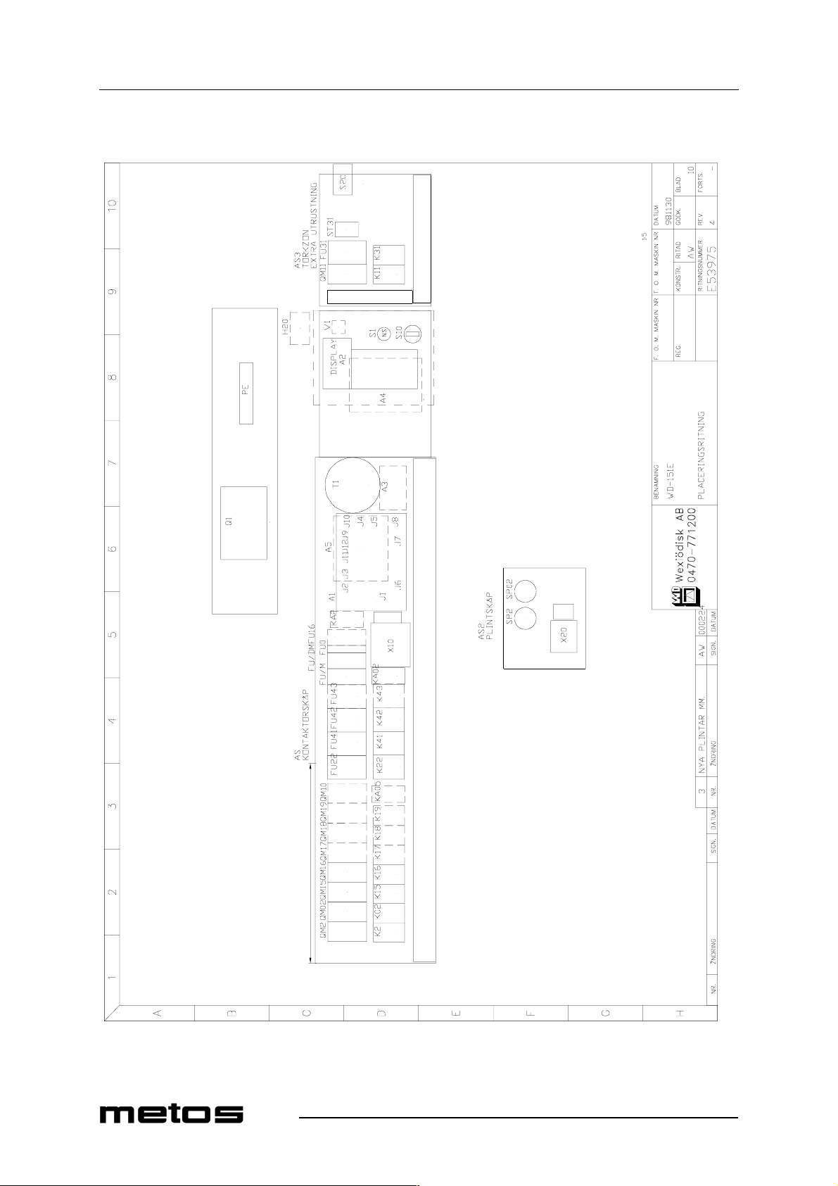
MODULE:Electric components [151E nor] A1 5315258 E H Circuit board
61007950 E H Eprom symb
61007960 E H Eprom text
61007970 E H Eprom symb
61008000 E H Eprom text A2:1 5320283 E H Cable
5320080 E H Panel card symb A2:2 5320054 E H Panel card text A3 5315250 E H Relay card A4 5320078 E H Frequency exch.
5320061 E H Eprom A5 532 00 81 E H In te rface board C1 5315409 E H RC-unit C2 5315409 E H RC-unit FU/DM 5320077 E H Automatic fu se FU/M 5320077 E H Automatic fuse FU0 64800110 E H Automatic fuse FU16 5320077 E H Automatic fuse FU22 64800340 E H Automatic fuse FU41 64800340 E H Automatic fuse FU42 64800340 E H Automatic fuse FU43 64800340 E H Automatic fuse FV1 5320065 E H Varistor H20 55500242 E H Signal light K02 5315527 E H Contactor K15 5315527 E H Contactor K16 5315527 E H Contactor K2 5315527 E H Contactor
5320287 E H Help cont. block K22 5315527 E H Contactor K41 5315527 E H Contactor K42 5315527 E H Contactor K43 5315527 E H Contactor
87
Page 88
Spare parts
4.12.2000 Rev. 2.2
88
e53975e.cgm
Page 89
4.12.2000 Rev. 2.2
Spare parts
ID Code Model Type Accessory Voltage Description
MODULE:Electric components [151E nor] KA02 5315244 E H Relay
5320046 E H Relay base KA2 5315244 E H Relay
5320046 E H Relay base KA20 5315244 E H Relay
5320046 E H Relay base Q1 60110050 E H Linebreaker
60105053 E H Knob
60104008 E H Protection QM02 5320070 E H Thermal relay
5320073 E H Extra conn. block QM15 5320069 E H Thermal relay
5320073 E H Extra conn. block QM16 5320069 E H Thermal relay
5320073 E H Extra conn. block QM2 5320288 E H Thermal relay
5320073 E H Extra conn. block S1 5320328 E H Emergency stop S10 5315246 E H Switch S30 5315331 E H Switch T1 5320086 E H Transformer V1 ACS121805EHDiod
Z1 61075646 E H Ferrit core SP02 5315791 E H Pressure switch SP2 5315791 E H P ressure switch FU31 64800325 E H Automatic fuse K11 63723113 E H Contactor K31 63723113 E H Contactor QM11 63113027 E H Thermal relay
5320073 E H Extra conn. block S20 5315331 E H Switch ST31 5315797 E H Thermostat
89
Page 90
Spare parts
4.12.2000 Rev. 2.2
90
Page 91
4.12.2000 Rev. 2.2
Spare parts
ID Code Model Type Accessory Voltage Description
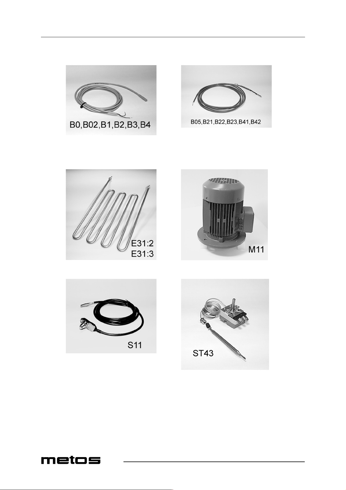
B0 5320290 E H Magnet switch B02 5320290 E H Magnet switch B2 5320290 E H Magnet switch B4 5320290 E H Magnet switch B05 5315465 E H Temp. givare B22 5315465 E H Temp. givare B41 5315465 E H Temp. givare B42 5315465 E H Temp. givare B43 5315465 E H Temp. givare E31.1 5315389 E H Heating el ement dryer E31.2 5315389 E H Heating element dryer E31.3 5315389 E H Heating el ement dryer M11 5320042 E H Blower dryer S11 5315377 E H Limit switch ST43 734.0302 E H Thermostat
91
Page 92
Spare parts
4.12.2000 Rev. 2.2
92
Page 93
4.12.2000 Rev. 2.2
Spare parts
ID Code Model Type Accessory Voltage Description
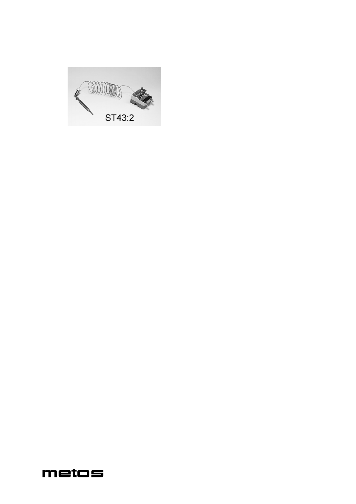
ST43:2 734.0201 E H Overheat protection
93
Page 94
Spare parts
4.12.2000 Rev. 2.2
94
e54871e.cgm
Page 95
4.12.2000 Rev. 2.2
Spare parts
ID Code Model Type Accessory Voltage Description
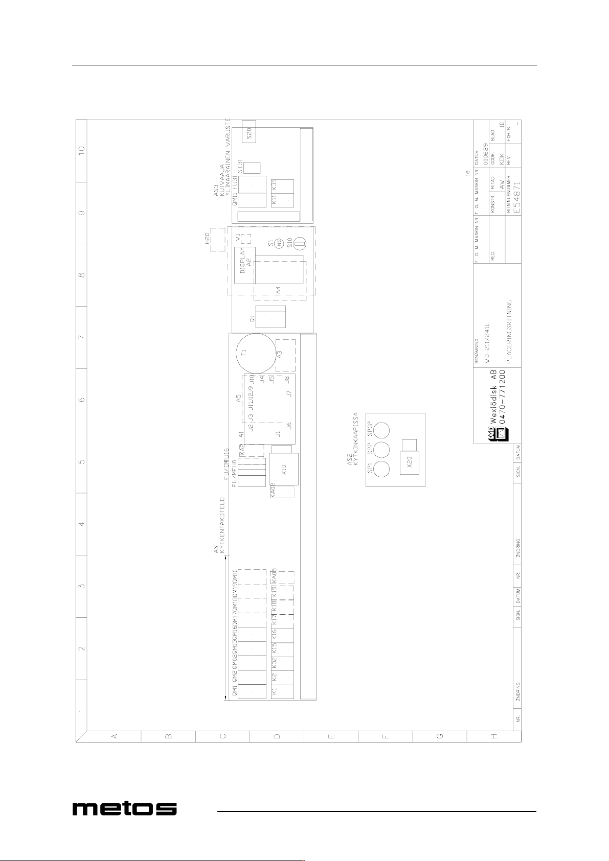
MODULE:Electric components [151E steam] A1 5315258 S L Circuit board
61008030 S L Eprom symb 61008010 S L Eprom text 61008020 S L Eprom text fra 61007950 S L Eprom symb 61007960 S L Eprom text 61007970 S L Eprom symb 61008000 S L Eprom text
A2:1 5320283 S L Cable
5320080 S L Panel ca r d sym b A2:2 5320054 S L Panel card text A3 5315250 S L Relay card A4 5320078 S L Frequency exch.
5320061 S L Eprom A5 5320081 S L Interface board C1 5315409 S L RC-unit C2 5315409 S L RC-unit FU/DM 5320077 S L Automatic fuse FU/M 5320077 S L Automatic fuse FU0 5320076 S L Automatic fuse FU16 5320076 S L Automatic fuse FV1 5320065 S L Varistor H20 55500242 S L Signal light K02 5315527 S L Contactor K15 5315527 S L Contactor K16 5315527 S L Contactor K2 5315527 S L Contactor
5320287 S L Help cont. block
95
Page 96
Spare parts
4.12.2000 Rev. 2.2
96
e54871e.cgm
Page 97
4.12.2000 Rev. 2.2
Spare parts
ID Code Model Type Accessory Voltage Description
MODULE:Electric components [151E steam] KA02 5315244 S L Relay
5320046 S L Relay base KA2 5315244 S L Relay
5320046 S L Relay base KA20 5315244 S L Relay
5320046 S L Relay base Q1 5320047 S L Linebreaker
5320048 S L Knob
5320049 S L Axel
5320083 S L Extra conn. block QM02 5320070 S L Thermal relay
5320073 S L Extra conn. block QM2 63113027 S L Thermal relay
63713042 S L Extra conn. block
5320084 S L Connec. bloc
63713085 S L C onn. bar QM15 5320069 S L Thermal relay
5320073 S L Extra conn. block QM16 5320070 S L Thermal relay
5320073 S L Extra conn. block S1 5320328 S L Emergency stop S10 5315246 S L Switch S30 5315331 S L Switch T1 60681064 S L Transformer V1 ACS121805S L Diod
Z1 61075646 S L Ferrit core SP02 5315791 S L Pressure switch SP1 5315791 S L Pressure switch SP2 5315791 S L Pressu re switch FU31 5315554 S L Automatic fuse K11 63723113 S L Contactor K31 63723113 S L Contactor QM11 5320071 S L Thermal relay
63704900 S L Extra conn. block S20 5315331 S L Switch ST31 5315797 S L Thermostat
97
Page 98
Spare parts
4.12.2000 Rev. 2.2
98
Page 99
4.12.2000 Rev. 2.2
Spare parts
ID Code Model Type Accessory Voltage Description
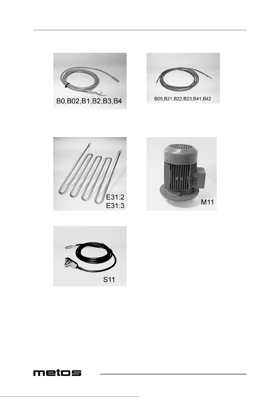
B0 5320290 S L Magnet switch B02 5320290 S L Magnet switch B2 5320290 S L Magnet switch B4 5320290 S L Magnet switch B05 5315465 S L Temp. givare B22 5315465 S L Temp. givare B41 5315465 S L Temp. givare B42 5315465 S L Temp. givare B43 5315465 S L Temp. givare E31.1 5315389 S L Heating element dryer E31.2 5315389 S L Heating element dryer E31.3 5315389 S L Heating element dryer M11 5320042 S L Blower dryer S11 5315377 S L Limit switch
99
Page 100
Spare parts
4.12.2000 Rev. 2.2
100
 Loading...