

Page 1

5TE
Page 2

TABLE OF CONTENTS
1. Introduction ..............................................................................................1
2. Operation ...................................................................................................2
2.1 Installation ................................................................................................2
2.2 Removing the Sensor ................................................................................. 4
2.3 Connecting .................................................................................................4
2.3.1 Connect to METER Data Logger ........................................................ 5
2.3.2 Connect to a Non-METER Data Logger ............................................. 5
2.4 Communication .........................................................................................6
3. System .........................................................................................................8
3.1 Specifications ............................................................................................8
3.2 About 5TE ................................................................................................ 11
13509-10
2.28.2019
3.3 Theory ...................................................................................................... 12
3.3.1 Volumetric Water Content .............................................................. 12
3.3.2 Temperature ..................................................................................12
3.3.3 Electrical Conductivity ..................................................................12
3.3.4 Converting Bulk EC to Pore EC .......................................................13
3.3.5 Pore Water Versus Solution EC ....................................................... 14
4. Service ....................................................................................................... 15
4.1 Calibration ............................................................................................... 15
4.1.1 Dielectric Permittivity ....................................................................15
4.1.2 Mineral Soil Calibration .................................................................15
4.1.3 Calibration in Soilless Media .........................................................16
4.2 Cleaning and Maintenance .......................................................................16
4.3 Troubleshooting ....................................................................................... 17
i
Page 3

5TE
4.4 Customer Support....................................................................................18
4.5 Terms and Conditions ..............................................................................19
References ....................................................................................................21
Index .................................................................................................................22
ii
Page 4
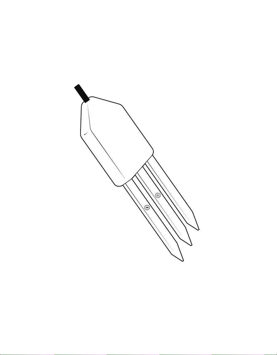
iii 1
Page 5

5TE
1. INTRODUCTION
Thank you for choosing the ECH2O 5TE Volumetric Water Content (VWC), Temperature, and
Electrical Conductivity (EC) sensor from METER Group.
This manual guides the customer through the sensor features and describes how to use the
sensor successfully. METER hopes the contents of this manual are useful in understanding
the instrument and maximizing its benefit.
Prior to use, verify the 5TE arrived in good condition.
Page 6

OPERATION
2. OPERATION
Please read all instructions before operating the 5TE to ensure it performs to its full
potential.
PRECAUTIONS
METER sensors are built to the highest standards, but misuse, improper protection, or
improper installation may damage the sensor and possibly void the manufacturer’s warranty.
Before integrating 5TE into a system, make sure to follow the recommended installation
instructions and have the proper protections in place to safeguard sensors from damage.
2.1 INSTALLATION
When selecting a site for installation, remember that the soil adjacent to the sensor surface
has the strongest influence on the sensor reading and that the sensor measures the VWC
of the soil. Therefore, any air gaps or excessive soil compaction around the sensor and in
between the sensor prongs can profoundly influence the readings.
• If installing sensors in a lightning-prone area with a grounded data logger, please read
Lightning surge and grounding practices.
• Test the sensors with the data logging device and software before going to the field.
Do not install the sensor adjacent to large metal objects such as metal poles or stakes. This
can attenuate the sensor's electromagnetic field and adversely affect readings. In addition,
the 5TE sensor should not be installed within 5 cm of the soil surface, or the sensing volume
of the electromagnetic field can extend out of the soil and reduce accuracy.
Because the 5TE has gaps between its prongs, it is also important to consider the particle
size of the medium. It is possible to get sticks, bark, roots or other material stuck between
the sensor prongs, which will adversely affect readings. Finally, be careful when inserting the
sensors into dense soil, as the prongs can break if excessive sideways force is used when
pushing them in.
When installing the 5TE, it is imperative to maximize contact between the sensor and soil.
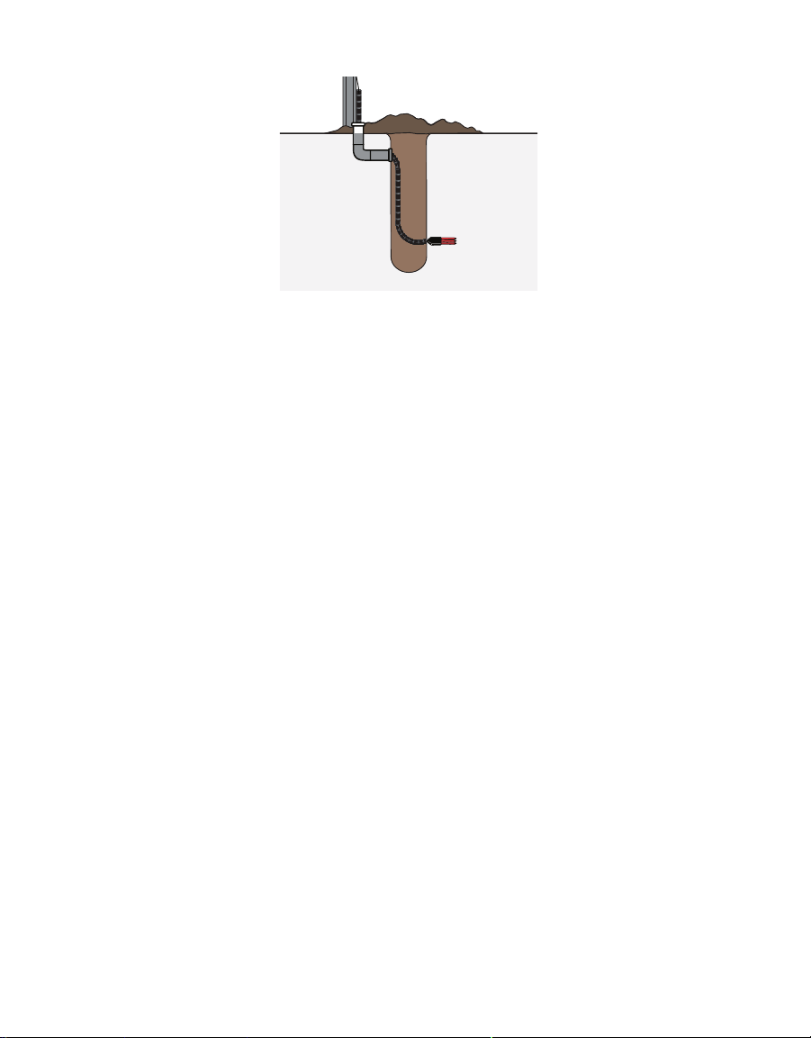
The sensor body needs to be completely covered by soil (Figure1).
2
Page 7
5TE
ERROR
OK
TEST
(–)
(+)
(–)
(+)
(–)
(+)
(+)
(–)
(+)
(–)
P1 P2 P3 P4 P5 P6
Figure1 Example of 5TE proper installation
For most accurate results, the sensor should be inserted into undisturbed soil. There are two
basic methods to accomplish a high-quality installation.
With either of these methods, the sensor may still be difficult to insert into extremely
compact or dry soil.
NOTE: Never pound the sensor into the soil! If there is difficulty inserting the sensor, loosen or wet the soil. This will
result in inaccurate VWC measurements until the water added during installing redistributes into the surrounding soil
METHOD 1. HORIZONTAL INSTALLATION
1. Excavate a hole or trench a few centimeters deeper than the depth at which the sensor
is to be installed.
2. At the installation depth, shave off some soil from the vertical soil face exposing
undisturbed soil.
3. Insert the sensor into the undisturbed soil face until the entire sensor is inserted. The
tip of each prong has been sharpened to make it easier to push the sensor into the soil.
Be careful with the sharp tips!
4. Backfill the trench taking care to pack the soil back to natural bulk density around the
sensor body of the 5TE.
METHOD 2. VERTICAL INSTALLATION
1. Auger a 3-in hole to the depth at which the sensor is to be installed.
2. Insert the sensor into the undisturbed soil at the bottom of the auger hole using a hand
or any other implement that will guide the sensor into the soil at the bottom of the hole.
Many people have used a simple piece of PVC pipe with a notch cut in the end for the
sensor to sit in, with the sensor cable routed inside the pipe.
3. After inserting the sensor, remove the installation device and backfill the hole taking
care to pack the soil back to natural bulk density while not damaging the black
overmolding of the sensor and the sensor cable in the process.
3
Page 8

PERATION
O
View a visual demonstration on proper installation of the sensor in How to install soil
moisture sensors.
The sensor can be oriented in any direction. However, orienting the flat side perpendicular
to the surface of the soil will minimize effects on downward water movement. The sensor
measures the average VWC along its length, so a vertical installation will integrate VWC over
a 10-cm depth while a horizontal orientation will measure VWC at a more discrete depth.
The 5TE sensor makes EC measurements by exciting one screw on the sensor and measuring
the current that moves from that screw to the adjacent grounded screw. The distance
between the screws is an important part of the EC calculation. If 5TE sensors are placed
close together (within 20 cm), it is possible for some of the current that leaves the excited
screw to pass through the nearby sensor ground screw, thus producing an erroneous
sensor reading.
This problem occurs regardless of which logging system is being used if the ground wires
are connected at all times. If sensors must be close together (e.g., column experiments),
consider a multiplexing option that would isolate the ground wires.
If installing sensors vertically at short depth intervals, do not bury them directly over the top
of each other. Although at times the vertical distance may be less than 20 cm, the sensors
can be staggered horizontally so they are not directly above each other, thus meeting the
distance requirement.
2.2 REMOVING THE SENSOR
When removing the sensor from the soil, do not pull it out of the soil by the cable! Doing so
may break internal connections and make the sensor unusable.
2.3 CONNECTING
The 5TE works seamlessly with METER data loggers. The 5TE can also be used with other
data loggers, such as those from Campbell Scientific, Inc. For extensive directions on how to
integrate the sensors into third-party loggers, refer to the 5TE Integrator Guide.
5TE sensors require an excitation voltage in the range of 3.6 to 15 VDC. 5TE can be integrated
using DDI serial or SDI-12 protocol. See the 5TE Integrator Guide for details on interfacing
with data acquisition systems.
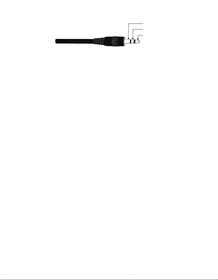
The 5TE sensors come with a 3.5-mm stereo plug connector (Figure2) to facilitate easy
connection with METER loggers. 5TE sensors may be ordered with stripped and tinned wires
to facilitate connecting to some third-party loggers (Section2.3.2).
4
Page 9
5TE
Ground
Data output
Power
Figure2 3.5-mm stereo plug connector wiring
The 5TE comes standard with a 5-m cable. It may be purchased with custom cable lengths for
an additional fee (on a per-meter basis). METER has successfully tested digital communication
on cable lengths up to 1,000 m (3,200 ft). This option eliminates the need for splicing the cable
(a possible failure point). However, the maximum recommended length is 75 m.
2.3.1 CONNECT TO METER DATA LOGGER
The 5TE sensor works most efficiently with METER ZENTRA series data loggers. Check the
METER download webpage for the most recent data logger firmware. Logger configuration
may be done using either ZENTRA Utility (desktop and mobile application) or ZENTRA Cloud
(web-based application for cell-enabled ZENTRA data loggers).
1. Plug the stereo plug connector into one of the sensor ports on the logger.
2. Use the appropriate software application to configure the chosen logger port for the 5TE.
3. Set the measurement interval.
METER data loggers measure the 5TE every minute and return the minute-average data
across the chosen measurement interval.
5TE data can be downloaded from METER data loggers using either ZENTRA Utility or
ZENTRA Cloud. Refer to the logger user manual for more information about these programs.
2.3.2 CONNECT TO NONMETER DATA LOGGER
The 5TE sensor can be used with non-METER (third-party) data loggers. Refer to the thirdparty logger manual for details on logger communications, power supply, and ground ports.
The 5TE Integrator Guide also provides detailed instructions on connecting sensors to
non-METER loggers.
5TE sensors can be ordered with stripped and tinned (pigtail) wires for use with screw
terminals. Refer to the third-party logger manual for details on wiring.
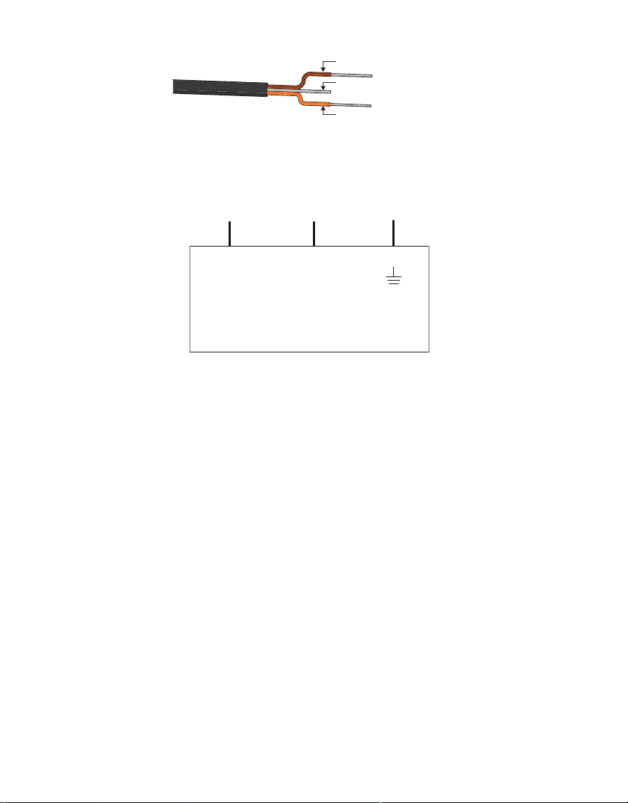
Connect the 5TE wires to the data logger as illustrated in Figure3 and Figure4, with the
power supply wire (brown) connected to the excitation, the digital out wire (orange) to a
digital input, and the bare ground wire to ground.
5
Page 10
OPERATION
Power (brown)
Ground (bare)
Data output (orange)
Figure3 Pigtail wiring
NOTE: Some 5TE sensors may have the older Decagon wiring scheme where the power supply is white, the digital out
is red, and the bare wire is ground.
Power
(brown)
Excitation Digital
Data output
(orange)
in
Ground
(bare)
Ground
Data Logger
Figure4 Wiring diagram
NOTE: The acceptable range of excitation voltages is from 3 to 15 VDC. To read 5TE sensors with Campbell Scientific
data loggers, power the sensor from a switched 12-V port or a 12-V port if using a multiplexer.
If the 5TE cable has a standard stereo plug connector and needs to be connected to a
non-METER data logger, please use one of the following two options.
Option 1
1. Clip off the stereo plug connector on the sensor cable.
2. Strip and tin the wires.
3. Wire it directly into the data logger.
This option has the advantage of creating a direct connection with no chance of the sensor
becoming unplugged. However, it then cannot be easily used in the future with a METER
readout unit or data logger.
Option 2
Obtain an adapter cable from METER.
The adapter cable has a connector for the stereo plug connector on one end and three wires
(or pigtail adapter) for connection to a data logger on the other end. The stripped and tinned
adapter cable wires have the same termination as in Figure4: the brown wire is excitation,
the orange is output, and the bare wire is ground.
NOTE: Secure the stereo plug connector to the pigtail adapter connections to ensure the sensor does not become
disconnected during use.
6
Page 11

5TE
50
Because 5TE sensors use digital communication, they require special considerations
when connecting to an SDI-12 data logger. Read SDI-12 example programs to view sample
Campbell Scientific programs.
2.4 COMMUNICATION
The 5TE sensor communicates using two different methods, DDI serial and SDI-12. Please
see the 5TE Integrator Guide for detailed instructions.
When using serial communication, the 5TE makes a measurment when excitation voltage is
applied. Within about 120 ms of excitation, three measurement values are transmitted to the
data logger as a serial stream of ASCII characters. The serial out is 1200 baud asynchronous
with 8 data bits, no parity, and 1 stop bit. The voltage levels are 0 to 3.6 V and the logic levels
are TTL (active low). The power must be removed and reapplied for a new set of values to be
transmitted.
The ASCII stream contains three numbers separated by spaces. The stream is terminated
with the carriage return character. The first number is raw dielectric output. The second
number is EC, and the third number is raw temperature. The following explains how to
convert the raw values into their standard units.
The raw dielectric value (
permittivity values 0.00 to 81.88. The 5TE uses the
dielectric permittivity portion of the sensor is not working as expected.
The
ε
value is converted to dielectric permittivity (ε
Raw
The raw temperature value (T
ε
) is valid in the range 0 to 4094. This corresponds to dielectric
Raw
ε
a
) is valid in the range 0 to 1022. The 5TE uses a compression
Raw
ε
value of 4095 to indicate the
Raw
) with the Equation
a
ε
Raw
=
Equation 1
algorithm to extend the range of temperatures that can be represented by a 10-bit value. The
sensor sends temperature with 0.1 of 1 °C resolution for the range −40 to 50.0 °C. For the
range 50.5 to 111.0 the sensor sends temperature with a 0.5 of 1 °C resolution. Temperatures
outside this range are truncated to the maximum or minimum values as appropriate.
The 5TE uses the
T
value of 1023 to indicate the temperature portion of the sensor is not
Raw
working as expected.
If
T
≤ 900, then T
Raw
If
T
> 900, then T
Raw
Temperature (°C)=(
= T
Raw2
= 900 + 5(T
Raw2
T
400)/10.
Raw2
Raw
.
900).
Raw
7
Page 12

3. SYSTEM
This section describes the 5TE sensor.
3.1 SPECIFICATIONS
MEASUREMENT SPECIFICATIONS
Volumetric Water Content (VWC)
Range
Mineral soil
0.0–1.0 m
calibration
Soilless media
0.0–1.0 m3/m
calibration
Apparent dielectric
permittivity (ε
a
1 (air) to 80 (water)
)
Resolution 0.0008 m
Accuracy
Generic calibration ± 0.03 m
Medium-specific
±0.02 m
calibration
Apparent dielectric
permittivity (ε
a
1–40 (soil range), ±1 ε
40–80, 15% measurement
)
Temperature
Range –40 to +60 °C
Resolution 0.1 °C
Accuracy ±1 °C
3/m3
3/m3
3/m3
3/m3
SYSTEM
3
from 0%–50% VWC
typical
(unitless)
a
Bulk Electrical Conductivity (EC)
Range 0–23 S/m (bulk)
Resolution 0.01 S/m from 0–7 S/m
0.05 S/m from 7–23 S/m
Accuracy ±10% from 0–7 S/m
User calibration required from 723 S/m
8
Page 13

5TE
COMMUNICATION SPECIFICATIONS
Output
DDI serial or SDI-12 communication protocol
Data Logger Compatibility
Data acquisition systems capable of 3.6- to 15.0-VDC power and serial or
SDI-12communication
PHYSICAL SPECIFICATIONS
Dimensions
Length 10.9 cm (4.3 in)
Width 3.4 cm (1.3 in)
Height 1.0 cm (0.4 in)
Prong Length
5.0 cm (1.9 in)
Operating Temperature Range
Minimum –40 °C
Typical NA
Maximum +60 °C
NOTE: Sensors may be used at higher temperatures under certain conditions; contactCustomer
Supportfor assistance.
Cable Length
5 m (standard)
75 m (maximum custom cable length)
NOTE: Contact Customer Support if a nonstandard cable length is needed.
Connector Types
3.5-mm stereo plug connector or stripped and tinnedwires
ELECTRICAL AND TIMING CHARACTERISTICS
Supply Voltage (VCC to GND)
Minimum 3.6 VDC
Typical NA
Maximum 15.0 VDC
9
Page 14

Digital Input Voltage (logic high)
Minimum 2.8 V
Typical 3.0 V
Maximum 3.9 V
Digital Input Voltage (logic low)
Minimum –0.3 V
Typical 0.0 V
Maximum 0.8 V
Power Line Slew Rate
Minimum 1.0 V/ms
Typical NA
Maximum NA
Current Drain (during measurement)
Minimum 0.5 mA
Typical 3.0 mA
Maximum 10.0 mA
SYSTEM
Current Drain (while asleep)
Minimum NA
Typical 0.03 mA
Maximum NA
Power-Up Time (DDI serial)
Minimum NA
Typical NA
Maximum 100 ms
Power-Up Time (SDI-12)
Minimum 100 ms
Typical 150 ms
Maximum 200 ms
10
Page 15
5TE
Connection cable
VWC sensor
Measurement Duration
Minimum NA
Typical 150 ms
Maximum 200 ms
COMPLIANCE
Manufactured under ISO 9001:2015
EM ISO/IEC 17050:2010 (CE Mark)
3.2 ABOUT 5TE
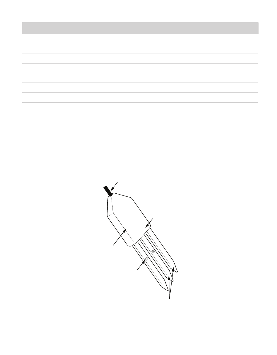
The 5TE is designed to measure the water content, EC, and temperature of soil (Figure5).
The 5TE uses an oscillator running at 70 MHz to measure the dielectric permittivity of soil
to determine the water content. A thermistor in thermal contact with the sensor prongs
provides the soil temperature, while the screws on the surface of the sensor form a
two-sensor electrical array to measure EC. The polyurethane coating on the 5TE circuit board
protects the components from water damage and gives the sensor a longer life span.
Polyurethane
overmolding
Screws for
two-point
electrical array
Figure5 5TE components
11
Thermal sensor
(thermistor)
Dielectric
Page 16

SYSTEM
3.3 THEORY
The following sections explain the theory of VWC, temperature, and EC measured by 5TE.
3.3.1 VOLUMETRIC WATER CONTENT
The 5TE sensor uses an electromagnetic field to measure the dielectric permittivity of the
surrounding medium. The sensor supplies a 70 MHz oscillating wave to the sensor prongs
that charges according to the dielectric of the material. The stored charge is proportional
to soil dielectric and soil VWC. The 5TE microprocessor measures the charge and outputs a
value of dielectric permittivity from the sensor.
3.3.2 TEMPERATURE
The 5TE uses a surface-mounted thermistor to take temperature readings. The thermistor is
underneath the sensor overmold, next to one of the prongs, and it reads the temperature of
the prong surface. The 5TE outputs temperature in degrees Celsius unless otherwise stated
in the software preferences file.
If the black polyurethane overmold of the sensor body is in direct sunshine, the temperature
measurement may read high. Do not install the sensor with the overmold in the sun.
3.3.3 ELECTRICAL CONDUCTIVITY
EC is the ability of a substance to conduct electricity and can be used to infer the amount
of charged molecules that are in solution. Measure EC by applying an alternating electrical
current to two electrodes and measuring the resistance between them. Conductivity is then
derived by multiplying the inverse of the resistance (conductance) by the cell constant (the
ratio of the distance between the electrodes to their area).
The 5TE uses a two-sensor array to measure the EC. The array is located on the screws of
two of the 5TE prongs. 5TE EC measurements are normalized to 25 °C. See Section4.2 for
instructions on cleaning the sensors if contamination occurs.
NOTE: Small amounts of oil from skin contact with the screws will cause significant inaccuracy in the
ECmeasurement.
The 5TE uses a two electrode array to measure the bulk EC of the surrounding medium.
METER calibrates the bulk EC measurement to be accurate within 10% from 0 to 7 dS/m.
This range is adequate for most field, greenhouse, and nursery applications. However, some
special applications in salt-affected soils may require measurements with bulk EC greater
than the specified range. The 5TE can measure up to 23.1 dS/m bulk EC but requires user
calibration above 7 dS/m. Additionally, EC measurements above 7 dS/m are sensitive to
contamination of the electrodes (e.g., skin oils). Read Section4.2 if measuring the EC of
saltysoils.
12
Page 17

5TE
50
3.3.4 CONVERTING BULK EC TO PORE EC
For many applications, it is advantageous to know the EC of the solution contained in the soil
pores (
σ
), which is a good indicator of the solute concentration in the soil. Researchers have
traditionally obtained
However, this is a time-consuming and labor-intensive process.
p
σ
by extracting pore water from the soil and measuring σp directly.
p
The 5TE measures the EC of the bulk soil surrounding the sensors (
σ
). METER has
b
conducted a considerable amount of research to determine the relationship between
σ
. Work by Hilhorst (2000) takes advantage of the linear relationship between the soil bulk
p
dielectric permittivity (
The 5TE measures
suited to this method.
ε
) and σb to allow accurate conversion from σb to σp if the εb is known.
b
ε
and σb nearly simultaneously in the same soil volume, so it is well
b
Use Hilhorst (2000) to derive the pore water conductivity (Equation 2).
εσ
=
p
pb
εε
−
σ
bb0
=
Equation 2
σ
where:
pore water EC (dS/m)
σ
=
p
real portion of the dielectric permittivity of the soil pore water (unitless)
ε
=
p
bulk EC (dS/m) measured directly by the 5TE
σ
=
b
the real portion of the dielectric permittivity of the bulk soil (unitless)
ε
=
b
ε
ε
can be calculated from soil moisture using a simple formula (Equation 3).
p
The 5TE measures T
the real portion of the dielectric permittivity of the soil when bulk EC is 0 (unitless)
=
σb = 0
ε
=− −
psoil
or soil temperature (°C) and
soil
T80.3 0.37 20
()
ε
. Convert raw VWC counts to bulk
b
Equation 3
dielectric with the 5TE dielectric calibration (Equation 4).
σ
and
b
ε
raw
ε
=
b
Finally, ε
(2000) recommends using
is an offset term loosely representing the dielectric of the dry soil. Hilhorst
σb = 0
ε
= 4.1 as a generic offset. However, METER research in several
σb = 0
agricultural soils, organic, and inorganic growth media indicates that
more accurate determinations of
σ
. Hilhorst (2000) offers a simple and easy method for
p
= 6 results in
ε
σb = 0
Equation 4
determining for individual soil types, which will improve the accuracy of the calculation of
in most cases.
13
σ
p
Page 18

SYSTEM
SolutionEC
()
0.7(0.1)0
0.43
0.162
pd
σθ σφθ
φ
=
+−
=
+
=
METER testing indicates that the above method for calculating σp results in good accuracy
(20%) in moist soils and other growth media. In dry soils where VWC is less than about
0.10 m³/m³, the denominator of pore water conductivity equation becomes very small,
leading to large potential errors. METER does not recommend this method to calculate
soils with VWC < 0.10 m³/m³.
σ
in
p
3.3.5 PORE WATER VERSUS SOLUTION EC
Pore water EC can be calculated from bulk EC using the sensor-measured dielectric
permittivity of the medium. However, pore water EC is not the same as solution EC. Pore
water EC is the EC of the water in the pore space of the soil. One could measure this directly
by squeezing the soil under high pressure to force water out of the soil matrix and test the
collected water for EC.
Solution EC is the EC of pore water removed from a saturated paste. In this case, wet the soil
with distilled water until the soil saturates, then place the soil on filter paper in a vacuum
funnel and apply suction. An EC measurement on the removed sample water gives the
solution EC. Theoretically, the two are related by the bulk density. An example calculation
illustrates this relationship. If a soil is at 0.1 m³/m³ VWC, has a pore water EC of 0.7 dS/m,
and a bulk density of 1.5 Mg/m³. Calculate the solution EC (dS/m) with Equation 5 and
Equation 6.
ρ
b
11
φ
=− =− =
ρ
s
In this example, φ is the porosity, ρb is bulk density, ρs is the density of the minerals (assumed
to be 2.65 Mg/m³), the subscript d is distilled water, and θ is VWC. It is assumed that the EC
of the distilled water is 0 dS/m. In practice, solution EC calculated from this method and
solution EC taken from a laboratory soil test may not correlate because wetting soil to a
saturated paste is very imprecise.
1.5
2.65
14
0.43
Equation 5
Equation 6
Page 19

5TE
4. SERVICE
This section contains calibration and recalibration information, calibration frequencies,
cleaning and maintenance guidelines, troubleshooting guidelines, customer support contact
information, and terms and conditions.
4.1 CALIBRATION
METER software tools automatically apply factory calibrations to the sensor output data.
However, this general calibration may not be applicable for all soil types. For added accuracy
METER encourages customers to perform soil-specific calibrations.
4.1.1 DIELECTRIC PERMITTIVITY
METER factory calibrates each 5TE sensor to measure dielectric permittivity (εa ) accurately
in the range of 1 (air) to 80 (water). The unprocessed raw values reported by the 5TE in
standard serial communication have units of 50
mode, the unprocessed values have units of
are 100
ε
).
a
4.1.2 MINERAL SOIL CALIBRATION
Numerous researchers have studied the relationship between dielectric permittivity and
VWC in soil. As a result, numerous transfer equations that predict VWC from measured
dielectric permittivity. Use any of these various transfer equations to convert raw dielectric
permittivity data from the 5TE into VWC. If using the mineral soil calibration option in METER
ProCheck reader, DataTrac 3, or ECH2O Utility, they convert raw dielectric permittivity values
with the Topp equation (Topp et al. 1980).
ε
. When used in SDI-12 communication
a
ε
(for 5TE board versions R2.04 and older, units
a
−− −−
VWC 4.3 10 5.5 10 2.92 10 5.3 10
=× −× +× −×
63 42 22
εε ε
aa a
Equation 7
METER tests show that in a properly installed 5TE sensor in a normal mineral soil with
saturation extract EC <10 dS/m, the Topp equation results in measurements within ±3%
VWC of the actual soil VWC. If a more accurate VWC is required, such as working in a soil with
very high EC or nonnormal mineralogy, then it may be necessary to conduct a soil-specific
calibration for the 5TE sensor to improve the accuracy to 1% to 2% for any soil.
There are two options for soil-specific calibration.
• Follow the step-by-step instructions for calibrating soil moisture sensors in the application
note Soil-specific calibrations for METER soil moisture sensors.
• METER offers a service providing soil specific calibrations.
This calibration service also applies to soilless materials, such as compost or potting
materials. Contact Customer Support for more information.
15
Page 20

SERVICE
4.1.3 CALIBRATION IN SOILLESS MEDIA
METER has performed calibrations with the 5TE in several soilless growth media. The
following are suggested calibration equations for some common materials.
Potting Soil
−−−
VWC 2.25 10 2.06 10 7.24 10 0.247
=× −× +× −
53 32 2
εεε
aaa
Equation 8
Rockwool
−−
VWC 1.68 10 6.56 10 0.0266
=× +× +
32 2
εε
aa
Equation 9
Perlite
−−
VWC 1.07 10 5.25 10 0.0685
=− ×+×−
32 2
εε
aa
Equation 10
METER continually develops additional calibration equations for various other growth media
as opportunities arise. Contact Customer Support for the status of this ongoing research.
The 5TE can accurately read VWC in virtually any porous medium if a custom calibration is
performed. Contact Customer Support for more information.
4.2 CLEANING AND MAINTENANCE
The EC measurement is very sensitive to the presence of nonconducting contamination
on the screws, especially at high EC. The most common source of contamination is skin oil
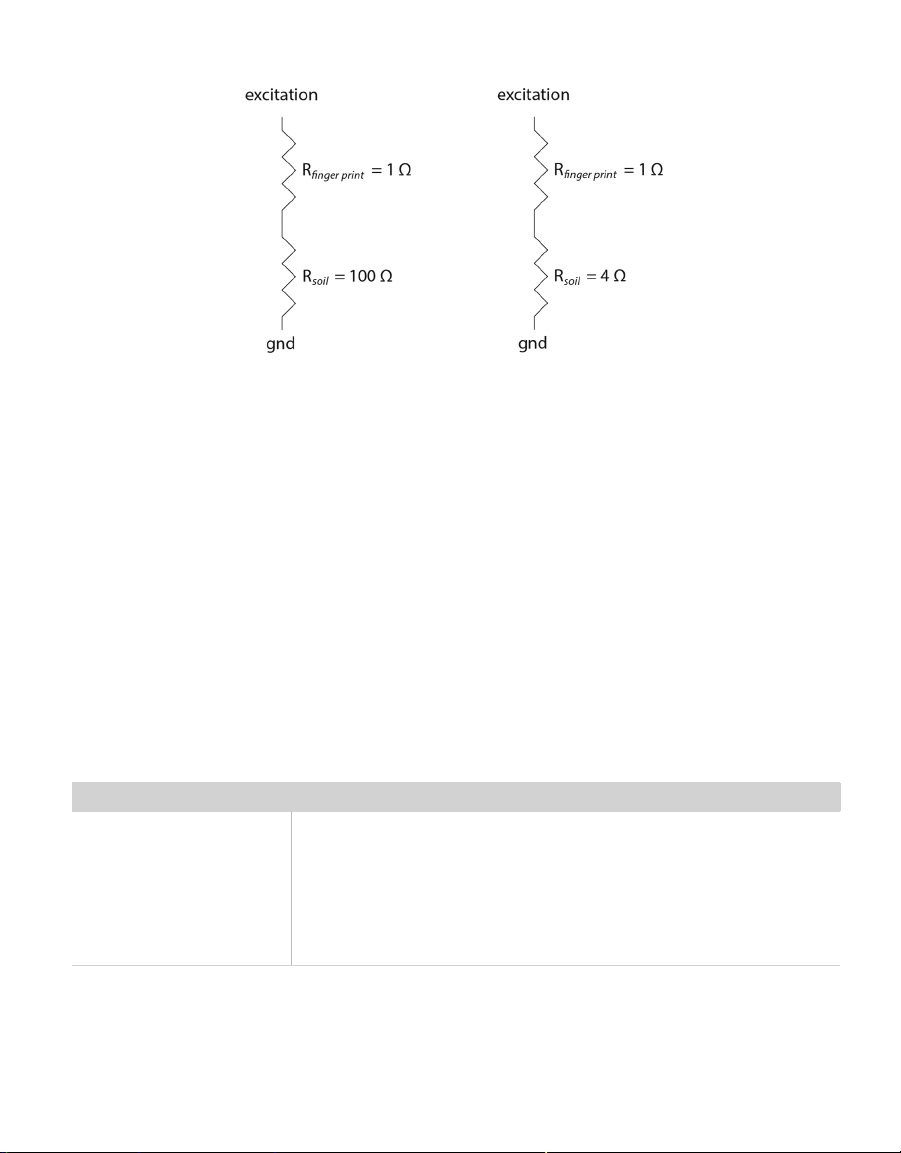
from handling the screws with bare hands. Figure6 shows the simplied electrical circuit
resulting from a fingerprint on the screw in a low EC soil and high EC soil, respectively. It is
apparent that in a low EC soil, the effects of contamination are relatively small, because the
resistance in the soil dominates the total resistance. However, in a high EC soil, the effects
of contamination become very large. This demonstrates the need to keep the screws clean,
especially when the sensor is to be used in high EC soil. Contamination of the screws during
handling and shipping prevent the factory calibration from being valid past 8 dS/m, although
the sensors will measure accurately at much higher EC with proper cleaning and calibration
by the user.
Figure6 shows a contaminated sensor in low EC (high resistance) soil, where
and a fingerprint causes a 1% error, and a simplied circuit for a contaminated sensor in high
EC (low-resistance) soil, where
R
= 5 Ω and a fingerprint causes a 25% error.
total
16
R
total
= 101 Ω
Page 21
5TE
Figure6 Simplified circuit in low EC soil (left) and in high EC soil (right)
Use the following steps to clean the sensor:
1. Clean the screws using a mild detergent such as liquid dish soap and a nonabrasive
sponge or cloth.
NOTE: Avoid detergents that contain lotions or moisturizers.
2. Rinse the sensor and screws thoroughly with tap or DI water.
Do not touch the screws without gloved hands and never contact the sensors with any
source of oil or other nonconducting residue.
4.3 TROUBLESHOOTING
If problems with the 5TE are encountered, they most likely manifest themselves in the form
of incorrect or erroneous readings. Review the information in Table 1 and the Troubleshooting
METER soil moisture sensors video to identify the problem. Contact Customer Support for
more information.
Table 1 Troubleshooting the 5TE
Problem Possible Solution
Check power to the sensor.
Check sensor cable and stereo plug connector integrity.
Sensor not responding
Check data logger wiring to ensure brown is power supply, orange is
digital out, and bare is ground.
NOTE: Some 5TE sensors may have the older Decagon wiring scheme where the
power supply is white, the digital out is red, and the bare wire is ground.
17
Page 22

Table 1 Troubleshooting the 5TE (continued)
Problem Possible Solution
Check for air gaps around sensor needles. These could be produced
below the surface of the substrate when the needle contacts a large
Sensor reading too low
(orslightly negative)
Sensor reading too high
Cable or stereo plug
connectorfailure
piece of material and pushes it out of the way or if the sensor is not
inserted perfectly linearly.
Ensure the calibration equation being used is appropriate for the media
type. There are significant differences between substrate calibrations,
so be sure to use the one specific to the substrate.
Check to make sure that the media was not packed excessively or
insufficiently during sensor installation. Higher density can cause
sensor reading to be elevated.
Ensure the calibration equation being used is appropriate for the media
type. There are significant differences between calibrations, so be sure
to use the one most suitable to the substrate, or consider developing a
substrate-specific calibration for the particular medium.
Some substrates have an inherently high dielectric permittivity (soils
of volcanic origin or high titanium, for instance). If the substrate has a
dry dielectric permittivity above 6, a custom calibration may need to
be performed. Soils with a bulk EC >10 dS/m require substrate-specific
calibrations (Section4.1).
If a stereo plug connector is damaged or needs to be replaced, contact
Customer Support for a replacement connector and splice kit.
If a cable is damaged, follow these guidelines for wire splicing and
sealing techniques.
SERVICE
4.4 CUSTOMER SUPPORT
NORTH AMERICA
Customer service representatives are available for questions, problems, or feedback Monday
through Friday, 7:00 am to 5:00 pm Pacific time.
Email: [email protected]
Phone: +1.509.332.5600
Fax: +1.509.332.5158
Website: metergroup.com
18
Page 23

5TE
EUROPE
Customer service representatives are available for questions, problems, or feedback Monday
through Friday, 8:00 to 17:00 Central European time.
Email: [email protected]
Phone: +49 89 12 66 52 0
Fax: +49 89 12 66 52 20
Website: metergroup.de
If contacting METER by email, please include the following information:
Name
Address
Phone
NOTE: For products purchased through a distributor, please contact the distributor directly for assistance.
Email address
Instrument serial number
Description of the problem
4.5 TERMS AND CONDITIONS
By using METER instruments and documentation, you agree to abide by the METER Group,
Inc. USA Terms and Conditions. Please refer to metergroup.com/terms-conditions fordetails.
19
Page 24

REFERENCES
REFERENCES
Hilhorst, M.A. 2000. "A Pore Water Conductivity Sensor." Soil Science Society of America
Journal 64, no. 6: 19221925.
Topp, G. Clarke, J.L. Davis, and A. Peter Annan. 1980. "Electromagnetic Determination of Soil
Water Content: Measurement in Coaxial Transmission Lines." Water Resources Research
16, no.3: 574582.
20
Page 25

INDEX
INDEX
A
accuracy 8
B
bulk EC 8, 13–14
C
cable length 9
calibration 15–16
cleaning 16
communication 7, 9
compliance 11
connecting
METER data logger 5
non-METER logger 5–6
connector types 9
customer support 18
D
data logger 4–6, 9
dielectric permittivity 8, 11, 13–15, 15
E
electrical conductivity 12–14
email address 18, 19
F
fax number 18, 19
I
installation 2
horizontal 3–4
vertical 3
integrator's guide 7
M
maintenance 16
measurements 8–10
mineral soil calibration 15
O
orientation 4
P
particle size 2
phone number 18, 19
pore EC 13–15
power requirements 9
R
range 8
references 20
S
specifications 8–11
communication 9
data logger compatibility 9
electrical and timing 9–10
measurement 8
physical 9
T
temperature 8, 9, 12
terms and conditions 19–20
theory 12–15
troubleshooting 17
V
volumetric water content 8, 12
W
wiring 6–7
Z
ZENTRA
ZENTRA Cloud 5
ZENTRA Utility 5
21
Page 26

14575-02
1.15.2019
2365 NE Hopkins Court Pullman, WA 99163
E: [email protected] W: metergroup.com
T: +49 89 12 66 52 0 F: +49 89 12 66 52 20
E: [email protected] W: metergroup.de
METER Group, Inc. USA
T: +1.509.332.5600 F: +1.509.332.5158
METER Group AG
Mettlacher Straße 8, 81379 München
© 2012, 2018−2019 All Rights Reserved.
Page 27

 Loading...