

Page 1

SATURO
Page 2

Page 3

14968-02
12.29.2017
TABLE OF CONTENTS
1. Introduction ..............................................................................................1
2. Operation ...................................................................................................2
2.1 Installation ................................................................................................2
2.2 Functionality .............................................................................................3
2.2.1 Setting up a Test ..............................................................................3
2.2.2 Starting a Test .................................................................................. 6
2.2.3 Stopping a Test ................................................................................7
2.2.4 Downloading Data ............................................................................ 7
3. System .........................................................................................................9
3.1 Specifications ............................................................................................9
3.2 Components ............................................................................................ 10
3.2.1 Control Unit ....................................................................................11
3.2.2 Insertion Ring ................................................................................ 17
3.2.3 Infiltrometer Head .........................................................................18
3.2.4 Water Supply Tank ......................................................................... 18
3.3 Theory ...................................................................................................... 19
4. Service ....................................................................................................... 23
4.1 Calibration ............................................................................................... 23
4.2 Maintenance ............................................................................................ 25
4.3 Troubleshooting ....................................................................................... 26
4.4 Customer Support....................................................................................29
4.5 Terms and Conditions ..............................................................................29
References ....................................................................................................32
Index .................................................................................................................33
i
Page 4
Enter
BACKPOWER / MENU
Page 5

SATURO
1. INTRODUCTION
Thank you for choosing the SATURO Infiltrometer from METER Group. This manual should
help you understand the functionality of SATURO, make high-quality Kfs measurements, and
get the most out of the instrument.
SATURO was designed to be an automated instrument for measuring permeability
and field saturated hydraulic conductivity (K
analysis approach to simplify the corrections for three-dimensional flow from a singlering infiltrometer, allowing for quick measurements of hydraulic conductivity without
needing postprocessing. This automated approach reduces error in the hydraulic
conductivity assessment (Reynold and Elrick 1990).
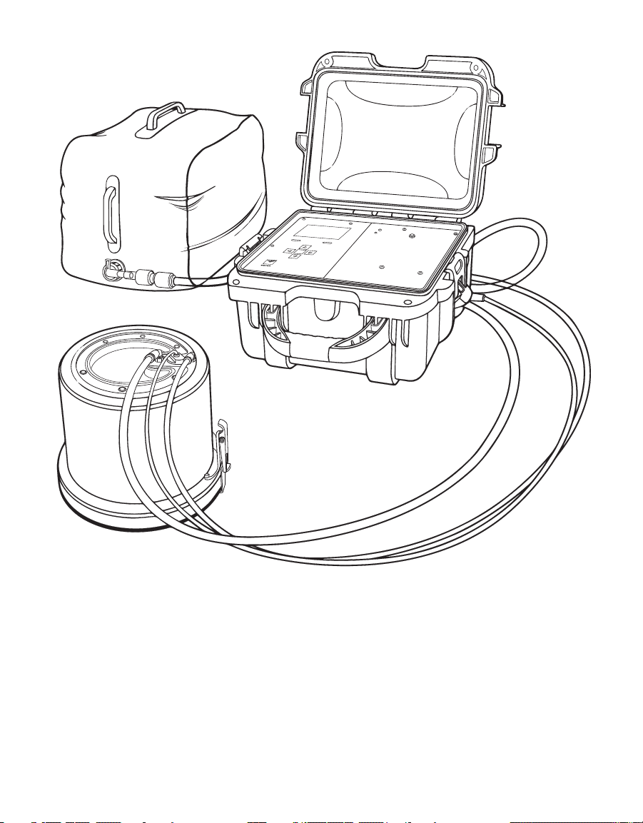
Verify all instrument contents shipped and appear in good condition:
• Control unit
• Two insertion rings: 5-cm depth and 10-cm depth
• Driving plate
• Infiltrometer head
• Charging adapter
• Two collapsible water tanks
• 6.4-mm (1/4-in) diameter tube for air output
• 9.5-mm (3/8-in) diameter tube for water output
• 7.9-mm (5/16-in) diameter tube for water input
• Metal file
• Driving mallet
• Flathead screwdriver
) in soil. It utilizes a multipressure head
f s
1
Page 6
OPERATION
2. OPERATION
Please read all instructions before operating the SATURO to ensure it performs to its
full potential.
2.1 INSTALLATION
Follow the steps listed in Table 1 to set up the instrument.
Table 1 Installation
Verify Access to Water
Identify a source of water on site or bring water to the site.
Charge Battery
Preparation
Charge the control unit battery.
Renew the charge after returning from the field.
Download Software
Install the SATURO Downloader to view files in the field (Section 2.2.4).
Install Insertion Ring
Remove rocks, sticks, and other large debris from the surface where the ring will
be installed at the desired test location.
Place the insertion ring on the soil and fit the driving plate on top.
Hammer on the inner circle of the driving plate until the insertion ring is flush
with the top of the soil, ensuring there are no gaps between the soil and ring
sidewalls.
Remove the driving plate.
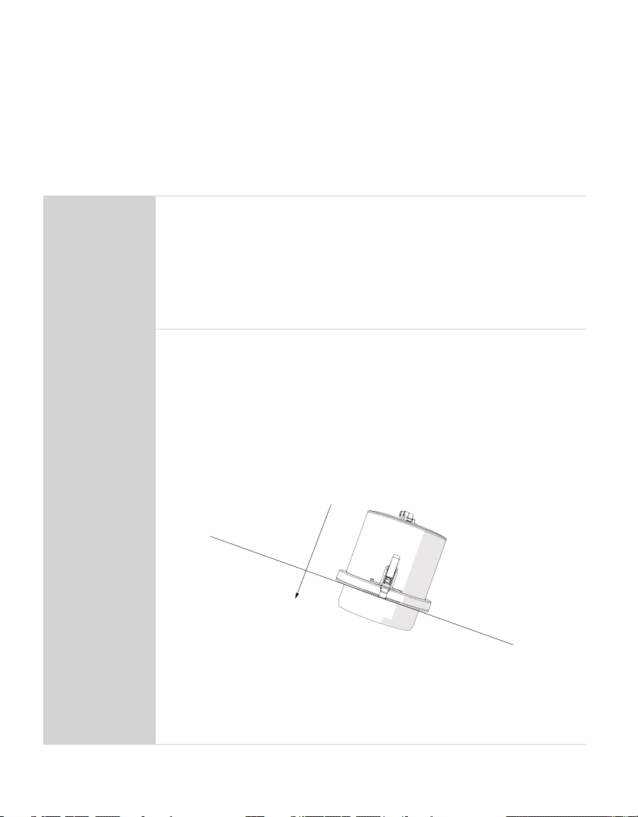
For hill installation, install the insertion ring so that the infiltrometer head will
be perpendicular to the slope of the hill with interior sensor to the left or right.
Installation
Set Up Infiltrometer Head
Clear all grass and debris from the lip of the insertion ring and clamp the
infiltrometer head onto the insertion ring to form a seal.
A clean seal ensures accurate pressure readings. Do not clamp too tightly, as this
can lead to warping of the insertion ring. Clamps can be tightened and loosened
with a small flat head screwdriver as needed.
2
Page 7
SATURO
Table 1 Installation (continued)
Connect the hoses and sensor cable to the designated fittings on the
infiltrometer head. Each input and output line is purposefully a different size of
tubing to help prevent a mismatch. If a tube does not snugly fit into a connection,
it is probably in the wrong one.
Set Up the Water Tank
Fill the water tank and connect it to the control unit.
Fully open the water valve.
Installation
(continued)
The water tank may not hold enough water for tests in highly permeable soils. To
use a larger container, place the tube at the bottom of the container and ensure
the tube remains underwater throughout the test.
Set Up Control Unit
Place the control unit on a stable surface.
Connect the three hoses and sensor cable to the corresponding ports on the
control unit.
Power on the control unit.
2.2 FUNCTIONALITY
Follow the steps in the following sections to collect data.
2.2.1 SETTING UP A TEST
1. Press the POWER/MENU button on the control unit to power on the device.
The last test results will appear on the screen.
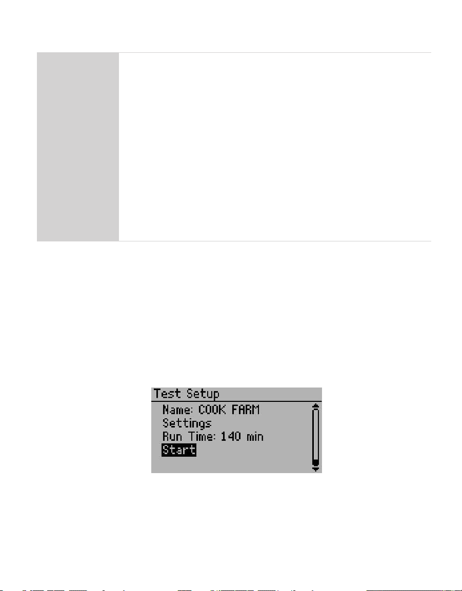
2. Press Enter to view the Test Setup screen
This screen is used to name the test and configure test settings (Figure1).
3. Name the test.
a. Select Name to create a test name.
Figure1 Test Setup screen
3
Page 8
OPERATION
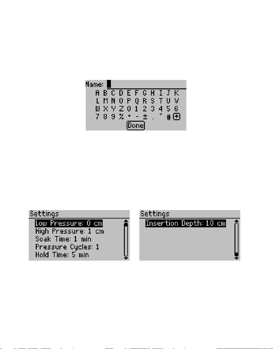
b. Highlight letters and press Enter after each one (Figure2).
A decimal point is not allowed as the first character of a test name.
Toggle between upper and lower case by selecting the boxed up arrow in the lower right
of the screen.
To add a space or delete a character, navigate to the test name and use the RIGHT or
LEFT buttons, respectively.
The test name can have up to 20 characters.
Figure2 Name screen
4. Select Done and press Enter to save the new test name.
Press BACK to cancel without saving changes.
NOTE: When downloading tests as a comma-separated value file format (*.csv), the degree symbol and ± symbol
are omitted from the test name in the test summary information.
5. Configure test settings by selecting Settings.
Different soil types may require different parameters for an optimum infiltration test.
Adjust settings to change pressure heads, soak time, number of cycles, and hold time as
well as to inform the control unit of the insertion ring depth (Figure3).
Figure3 Settings options
a. Set desired hydrostatic pressure.
Hydrostatic pressure for the low and high pressure heads must be between 0 and
40 cm. Generally, soils with high infiltration rates require lower pressure head settings
than soils with low infiltration rates. A pressure difference of at least 5 cm between
the low and high pressure heads is normally recommended, except in sites with high
infiltration rates. In such cases, a pressure difference of 2 cm is sufficient to help
4
Page 9

SATURO
reduce water usage. Table 2 provides rough guidelines to determine initial pressure
head settings. These values are starting points only and should be adjusted for the
particular soil based on experience.
b. Set soak time.
During soak time, the infiltrometer applies water to achieve saturation of the soil
before beginning the pressure cycles. A good introductory soak time is approximately
20 min, though the exact length depends largely on soil type and antecedent soil
moisture (Table 2). During soak time, pressure is maintained at the low pressure head.
Table 2 Soak time and pressure head configurations
Soak
Soil Type
Dry loamy sand 25 5 10 15 3 115
Wet loamy sand 15 5 10 15 2 75
Dry silt loam 30 5 15 20 3 150
Wet silt loam 15 5 15 20 2 95
Dry clay (poor structure) 30 5 20 25 3 180
Wet clay (poor structure) 15 5 20 25 2 115
Dry clay (strong structure) 25 5 10 20 3 145
NOTE: These values are a rough starting point only. Soil conditions dictate the optimal settings for the test. Use
lower pressure head settings for soils dominated by macropore flow. If necessary, reduce the pressure head settings
to allow the instrument to keep up with the flow rates.
Time
(min)
Low
Pressure
Head (cm)
High
Pressure
Head (cm)
Hold Time
at Pressure
(min)
Pressure
Cycles
(count)
Total
Run Time
(min)
c. Set the number of pressure cycles.
One pressure cycle is equivalent to a full run at the two different pressure heads. The
control unit takes the average infiltration rates at the different pressure heads during
the last pressure cycle to calculate K
. Multiple pressure cycles ensure the steady
f s
state infiltration rate was reached.
At first, the infiltration rate is large. Steady state or quasi-steady state may be
achieved when the infiltration rate charted over time levels into infinite time (Dane and
Topp 2002). Wait for the flux chart to stabilize to determine if quasi-steady state has
been reached. If there is a decrease in flux rate, redo the test or add another cycle.
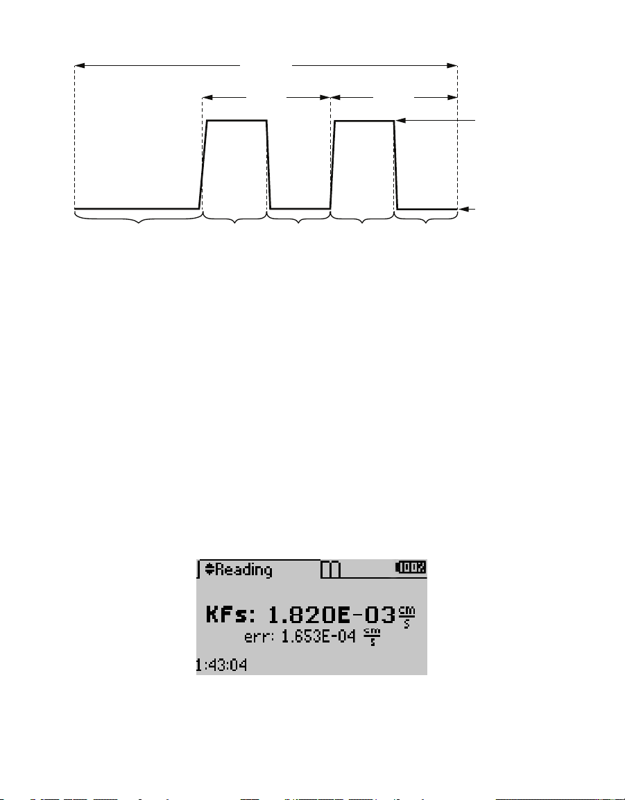
d. Set the hold time (Figure4).
The hold time determines how long the pressure is held at each pressure head and
applies to both pressure cycles (i.e., if the hold time is 20, both the low and high
pressure holds for 20 min).
e. Select the correct insertion ring depth.
5
Page 10
OPERATION
Run time
Cycle 2Cycle 1
High pressure
Low pressure
Soak Hold Hold Hold Hold
Figure4 Run time diagram
6. After the settings are configured, press BACK to go to the Test Setup screen.
2.2.2 STARTING A TEST
1. On the Test Setup screen, select Start.
The infiltrometer displays a message to check tubing and connections.
2. Press Enter to begin the test.
The infiltrometer will pump water from the water tank until the water level reaches 5 cm.
It then begins the soak time, while maintaining a level of 5 cm.
The graph feature displays incremental data during a test. The infiltrometer records a data
point every minute throughout the duration of the test.
3. It is not necessary to supervise the system during a test, but check the water level
intermittently to ensure a constant supply.
Test results will display automatically at the end of the test (Figure5).
NOTE: See Section 3.2.1 for details on viewing graphs of flux, water level, and pressure.
Figure5 Test complete screen
Pressing BACK returns the display to the Reading screens. Pressing Enter on any of the
Reading screens returns the display to the Name screen to review test settings.
6
Page 11
SATURO
2.2.3 STOPPING A TEST
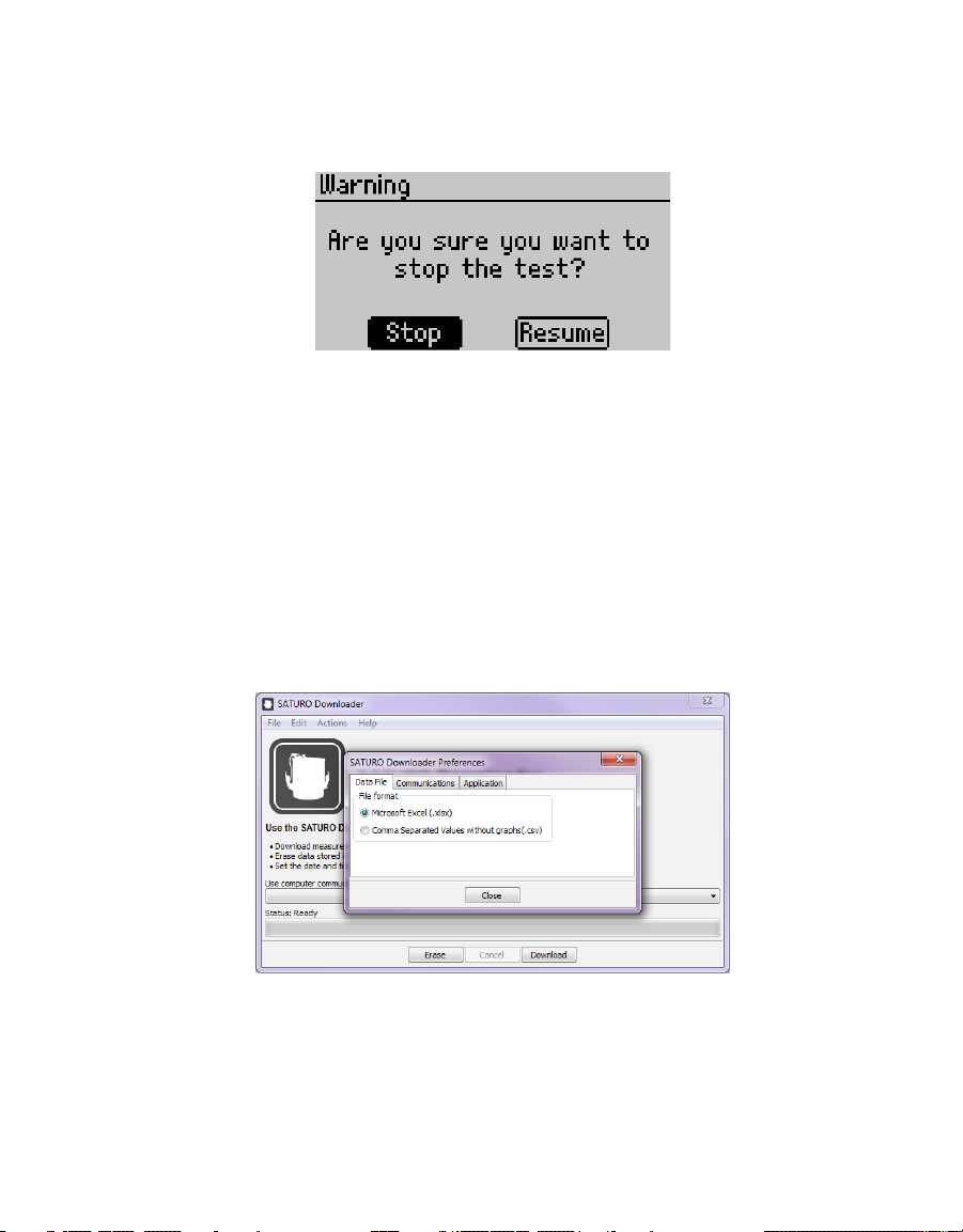
To stop a test, press BACK on any of the Reading screens and select Stop to cancel the
test(Figure6).
Figure6 Stop test warning
2.2.4 DOWNLOADING DATA
The SATURO Downloader application is used to download the data from SATURO, erase
stored data, set the date and time, and check for firmware updates for SATURO. Download
the application from metergroup.com/saturo-support before beginning the following steps.
1. Connect the USB cable to USB ports on a computer and on SATURO.
2. Open the SATURO Downloader application on the computer.
3. Select the file type by selecting Edit > Preferences > Data File and choosing the appropriate
file type (Figure7).
Data can be downloaded as .xlsx or .csv file.
Figure7 Change file type
7
Page 12
OPERATION
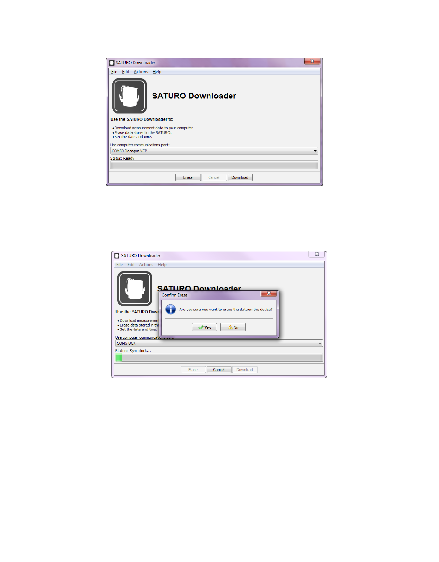
4. Select the proper COM port and click Download (Figure8).
Figure8 SATURO Downloader dialog
5. After the download is complete, a prompt will ask if the data stored on the device should
be erased (Figure9).
Select Yes or No.
Figure9 Confirm Erase prompt
8
Page 13

SATURO
Infiltration Rate
K
fs
K
Water Level
Maintained at 5 cm
Pressure Head Ranges
0–40 cm (vacuum is applied for <5 cm settings)
Operating Temperature
0–50 °C
PHYSICAL SPECIFICATIONS
Charging Adapter
Power supply
18 V; 2.2 A
Range
18–24 VDC
Output
USB
3. SYSTEM
This section describes the specifications, components, and theory of the SATURO system.
3.1 SPECIFICATIONS
MEASUREMENT SPECIFICATIONS
Range 0.0038–115.0000 cm/h
Resolution 0.0038 cm/h
Accuracy ±5% of reading
The
values that can be effectively measured by SATURO are limited by the
fs
listed minimum and maximum infiltration rates. These depend on the pressure
heads applied to the water during infiltration and to the three-dimensional flow
characteristics of the soil, so the measurement range of Kfs cannot be specified
explicitly. SATURO will generally be able to make measurements on poorly to
moderately structured soils as coarse as medium sand, but the maximum infiltration
rate can be exceeded by soils with excessive structure and especially by soils with
9
Page 14
Control Unit
31.8 cm (12.5 in) x 25.7 cm (10.1 in) x 15.3 cm (6.0 in)
Infiltrometer Head
Total height
18.3 cm (7.2 in)
Inner diameter
17.2 cm (6.75 in)
Insertion ring
Inner diameter
14.4 cm (5.68 in)
Insertion depth
5 cm (1.97 in)
10 cm (3.94 in)
Manufactured under ISO 9001:2015
Ente
r
BACK
P
O
W
ER
/ ME
NU
COMPLIANCE
2004/108/EC and 2011/65/EU
3.2 COMPONENTS
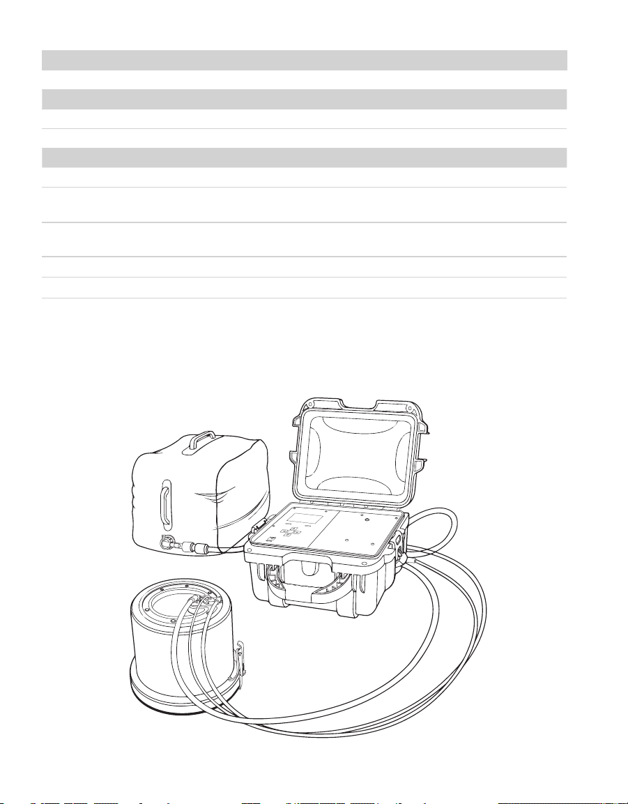
SATURO consists of four main components: the control unit, insertion ring, infiltrometer
head, and water supply tank (Figure10).
Figure10 SATURO components
Page 15
3.2.1 CONTROL UNIT
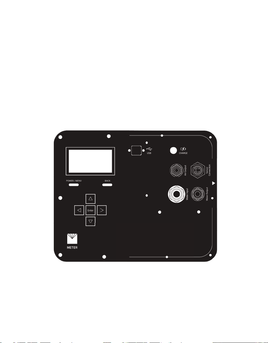
The SATURO control unit has seven buttons to navigate through screens and configure
settings (Figure11):
• When the device is off, press the POWER/MENU button to turn on the device.
Hold the POWER/MENU button down for more than 4 s to power off the device. This button
also navigates between different screen tabs.
• Pressing the BACK button returns the device to the parent screen. Pressing BACK on a
selection screen cancels any changes that have been made on that screen.
Holding BACK down for more than 7 s resets the device (hard reset).
• The UP, DOWN, LEFT, and RIGHT buttons on the directional pad allow navigation through
lists and scroll wheels. Pressing LEFT or RIGHT will highlight successive items in a list and
holding down the button will speed up scrolling.
• The Enter button selects the highlighted item to go to a submenu or save the highlighted
setting to memory.
Figure11 Control unit faceplate
The control unit is charged through a 18-V, 2.22-A, 40-W AC/DC charger. The unit takes
approximately 6 h to fully charge.
The control unit’s USB port takes a Type B to Type A USB to download data and to perform
firmware updates.
11
Page 16
SYSTEM
Configuration tab
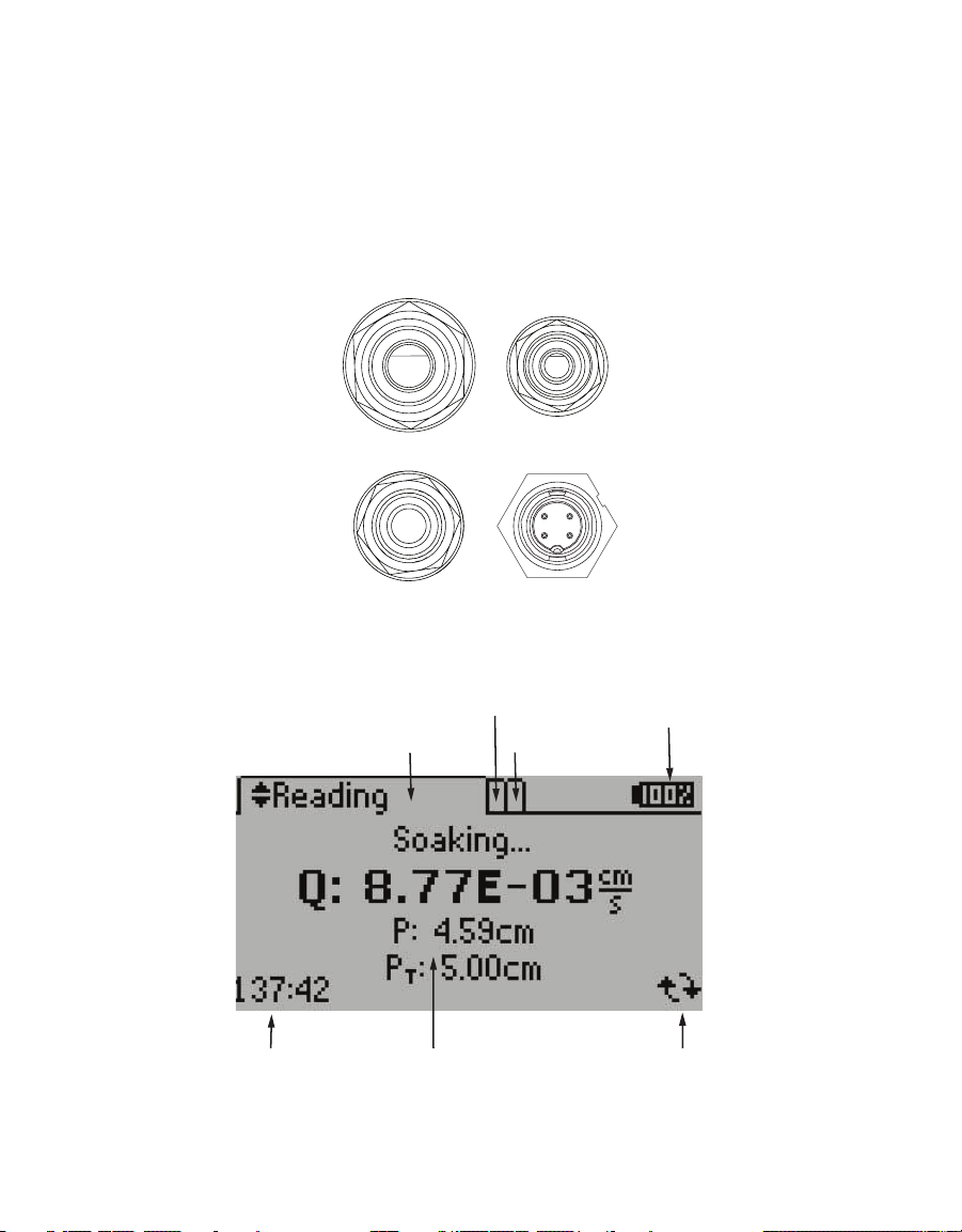
There are four connections on the control unit (Figure12):
• Top left connection is for the 7.9-mm (5/16-in) water input (water tank to control unit).
• Bottom left connection is for the 9.5-mm (3/8-in) water output (control unit to
infiltrometerhead).
• Bottom right connection is for the sensor connection to the infiltrometer head.
• Top right connection is a 6.4-mm (1/4-in) air output (control unit to infiltrometer head).
Water input
Air input
Water output
Figure12 Control unit connections
Sensor
connection
The SATURO display (Figure13) features three main tabs designed for ease of use: Reading,
Configuration, and Data.
Battery level
Active tab
Data tab
Time remaining Test status
Figure13 SATURO display elements
Live updating
12
Page 17
SATURO
READING TAB
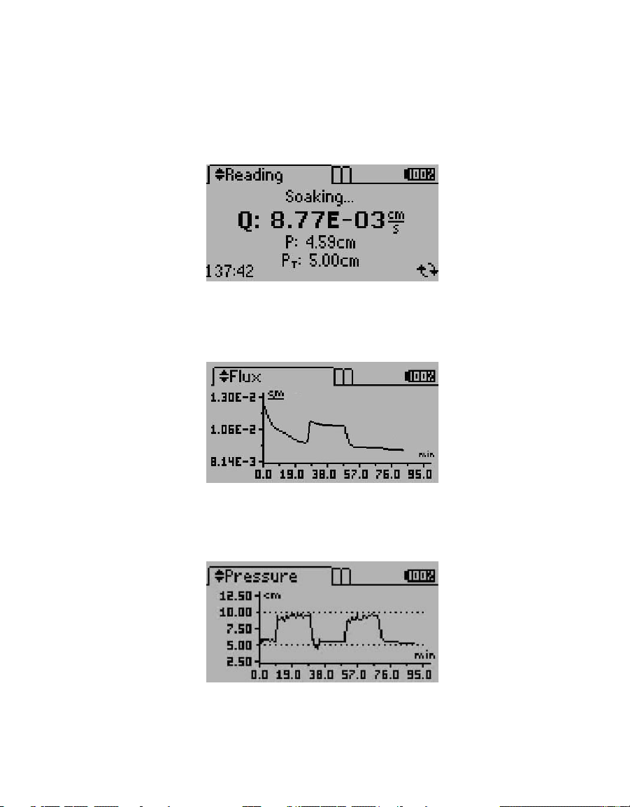
The Reading tab is used to view screens related to the current tests, including charts from
the most recent flux, pressure, and water level readings. Use UP and DOWN to scroll through
the available reading screens.
• Status Screen. The Status screen shows the test status as Soaking (Figure14). When the
test is completed, it changes to the Results screen.
Figure14 Status screen during test
• Flux Screen. The Flux screen displays the flow rate of water flow through the infiltrometer
on a graph updated every minute (Figure15). The current measurement is indicated by a
flashing dot.
Figure15 Flux screen
• Pressure Screen. The Pressure screen displays the hydrostatic pressure (combined air and
water pressure) on a graph updated every minute (Figure16). The current measurement is
indicated by a flashing dot.
Figure16 Pressure screen
13
Page 18
SYSTEM
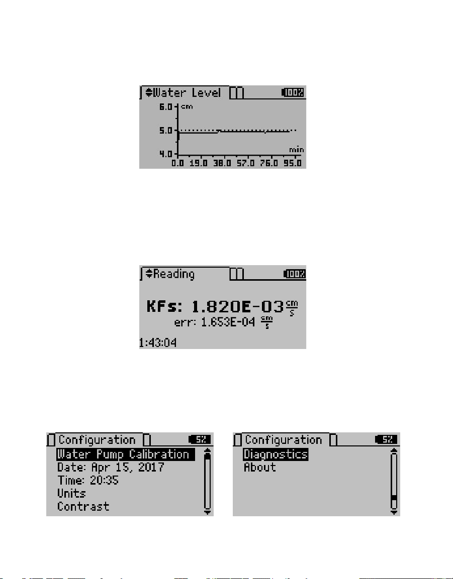
• Water Level Screen. After a test is started, the water level above the soil ramps up to 5 cm.
The Water Level screen displays the current water level on a graph that is updated every
minute (Figure17). The current point is indicated by a flashing dot.
Figure17 Water Level screen
• Results Screen. After a test is complete, the Results screen replaces the Status screen.
It shows the resulting Kfs of the test (Figure18). The error (err) value also appears on the
Results screen. The err is the standard error of the Kfs reading and represents the amount
of noise in the measurement. Press UP and DOWN to change Reading screens or press the
POWER/MENU button to navigate to the Configuration tab.
SATURO will display the results from the last test if no test is running.
Figure18 Results screen
CONFIGURATION TAB
The Configuration tab is used to view and set global preferences (Figure19). Press the
POWER/MENU button to navigate to the Configurationtab. Use the UP and DOWN buttons to
scroll through options.
Figure19 Configuration tab
• Water Pump Calibration. Water pump calibration is addressed in Section 4.1.
14
Page 19
SATURO
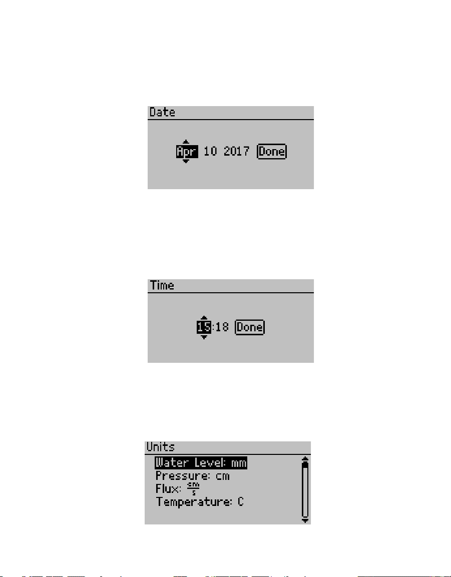
• Date. Edit this screen to change the date saved in the control unit (Figure20).
Select the Date option in the Configuration tab. Use UP and DOWN to change the current
value and hold the buttons down to scroll quickly. Press RIGHT to move to the next value or
press LEFT to return to the previous value. Select Done to save changes or press BACK to
cancel without saving changes.
Figure20 Editing Date option
• Time. Edit this screen to change the time saved in the control unit (Figure21).
Select the Time option in the Configuration tab. Use UP and DOWN to change the current
value and hold the buttons down to scroll quickly. Press RIGHT to move to the next value or
press LEFT to return to the previous value. Select Done to save changes or press BACK to
cancel without saving changes.
Figure21 Editing Time option
• Units. Edit the preferred units on all device screens and the units that appear in
downloaded data (Figure22).
Select the Units option in the Configuration tab. Press Enter to cycle through the available
options on the highlighted measurement. Press BACK to return to the previous menu.
Figure22 Editing Units options
15
Page 20
SYSTEM
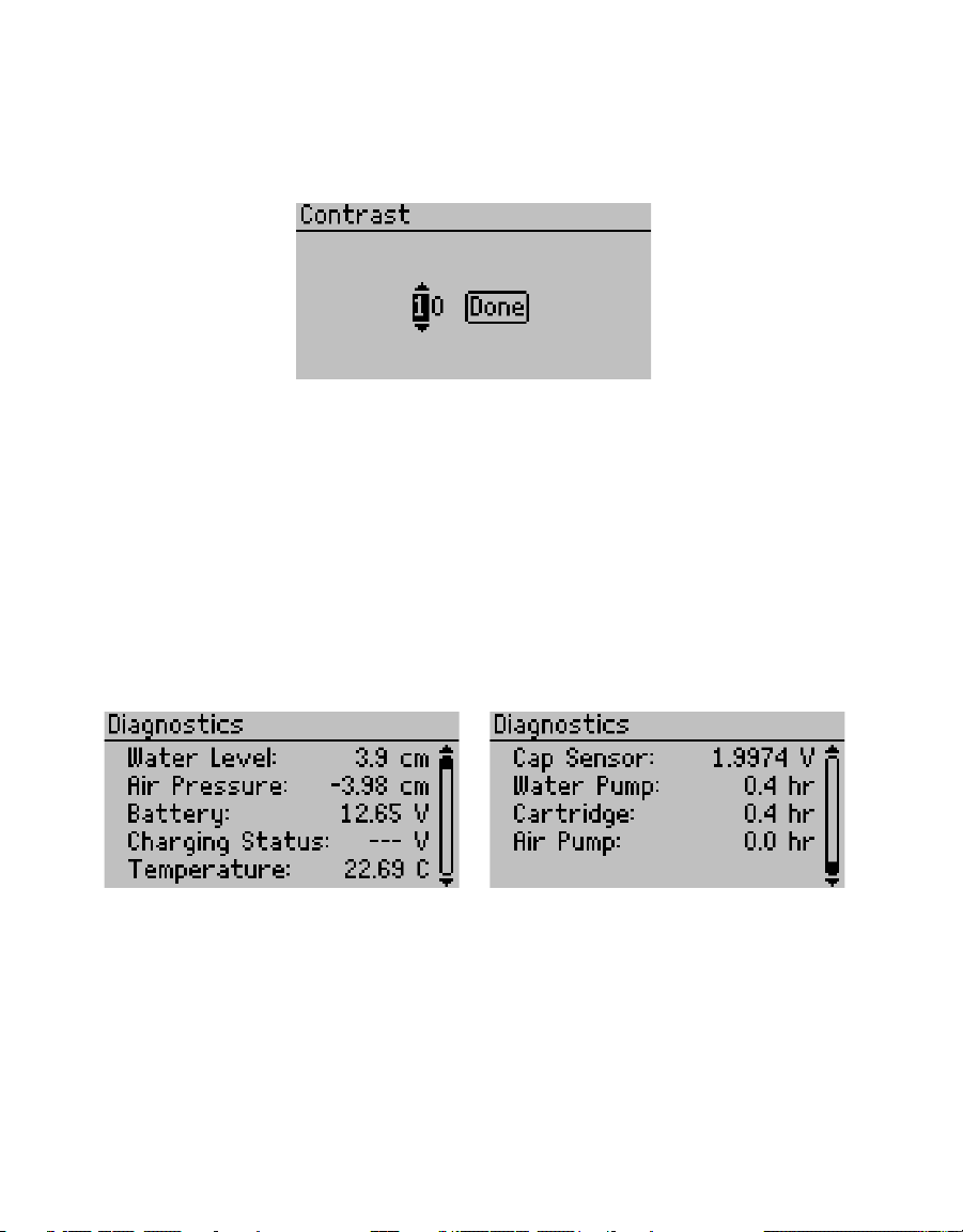
• Contrast. Change the screen lighting contrast settings (Figure23).
Select the Contrast option on the Configuration tab. Use the directional buttons to change
the contrast to any value from 00–25. Use RIGHT and LEFT to highlight Done and press Enter
to save the new contrast setting. Press BACK to exit without savingchanges.
Figure23 Editing Contrast option
• Diagnostics. Shows all the current readings from the instrument: water level (the current
water level above the soil); air pressure (pressure in the head space of the infiltrometer
assembly); battery (current battery voltage); charging status (observed voltage from
charging power supply); temperature (internal temperature of the control unit); and cap
sensor (measured voltage of the cap sensor, which is proportional to the humidity within
the control unit) (Figure24).
The Diagnostics option also tracks the usage information for the water pump , cartridge,
and air pump to track when parts need to be replaced. This screen provides valuable
information for maintenance and troubleshooting (Section 4.2). No changes can be made in
this screen.
Press BACK to return to the previous menu.
Figure24 Viewing the Diagnostics option
16
Page 21
SATURO
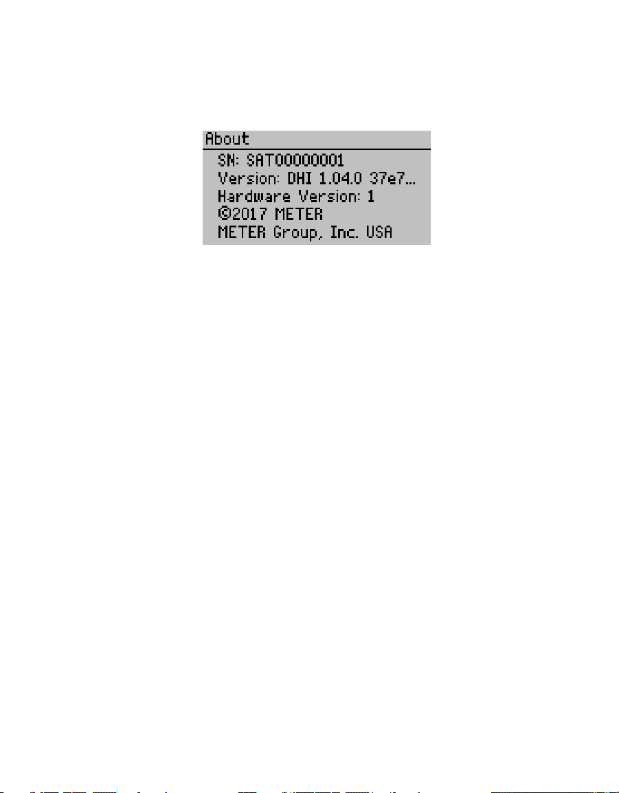
• About. Displays the instrument’s serial number, firmware version, hardware version,
copyright date, and manufacturer’s name (Figure25).
Select the About option on the Configuration tab and press Enter. No changes can be made
in this screen. Press BACK to return to the previous menu
Figure25 Viewing the About option
DATA TAB
The Data tab provides access to past test data. Press the POWER/MENU button to
navigate to this tab.
• View. Lists prior tests stored on the device, most recent first.
To view a test, scroll to desired test and press Enter. The Results (including final Kfs value,
water level chart, pressure chart, and flux chart), Settings, and Raw Data screens from that
test can all be viewed. Scroll through the available information by using the UP and DOWN
buttons. Press BACK to return to the previous screen.
• Delete. Deletes all test data in device memory. There is no way to delete individual tests or
readings from the infiltrometer, it erases all test data.
WARNING: Deleting test data permanently removes it from the control unit, and it cannot be recovered. It is
recommended that you download any test data prior to deleting the test data from the instrument.
3.2.2 INSERTION RING
The insertion ring is available in two depths: 5 cm and 10 cm. The 5-cm insertion ring
(Figure26) is primarily designed for sites with good soil structure. It reduces the impact
from inserting the ring, so it is recommended for most sites. The 10-cm insertion ring was
designed for sites with a disturbed or loose soil surface as well as sites with high fluxes due
to macropores. The deeper insertion ring can also be helpful in forest or organic soils with a
deep duff or organic layer at the surface.
17
Page 22
SYSTEM
14.4 cm
6 cm
5 cm
Figure26 5-cm insertion ring
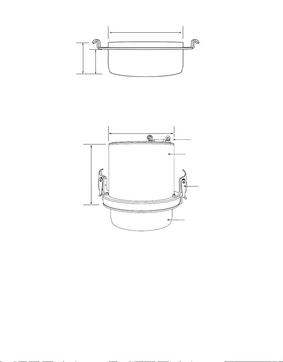
3.2.3 INFILTROMETER HEAD
The infiltrometer head houses the water level (depth) sensor (to control the water level),
water connection, and air connection with push-to-connect fittings (Figure27).
17.2 cm
Connectors
Infiltrometer head
18.3 cm
Ring clamps
Insertion ring
Figure27 Infiltrometer head
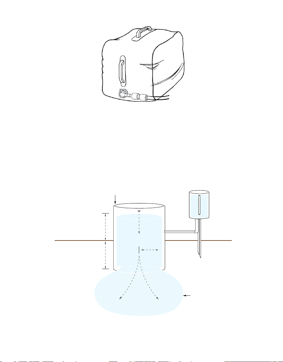
3.2.4 WATER SUPPLY TANK
The water supply tank holds up to 5 gal and is sufficient for lower permeability sites
(Figure28). Some sites with higher infiltration rates will use more than 5 gal of water in the
time necessary to complete a measurement. The Y-connector may be used to connect two
water tanks to SATURO, doubling the water supply available for a measurement.
18
Page 23
SATURO
Measuring
Figure28 Water tank
3.3 THEORY
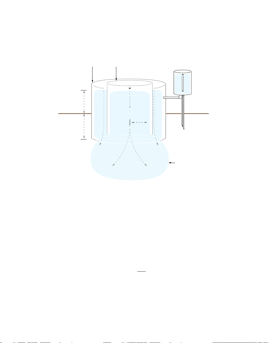
Field saturated hydraulic conductivity, Kfs (cm/s) is a fundamental soil hydraulic property
that describes the ease with which a fluid (usually water) can move through pore spaces or
fractures under field saturated conditions. One of the oldest and simplest methods for in situ
determination of Kfs has involved the measurement of ponded infiltration (D) from within a
single ring (with a radius b) pushed a small distance into the soil (d) (Figure29). The original
analysis used the measured steady flow rate, Qs(cm3/s), and assumed one-dimensional,
vertical flow to obtain Kfs from Bouwer (1986) and Daniel (1989).
cylinder
D
Water
b
d
Wetting
front
Figure29 Cross section of a single-ring infiltrometer
19
Mariotte
cylinder
Page 24
SYSTEM
Measuring
Buffer
F
i
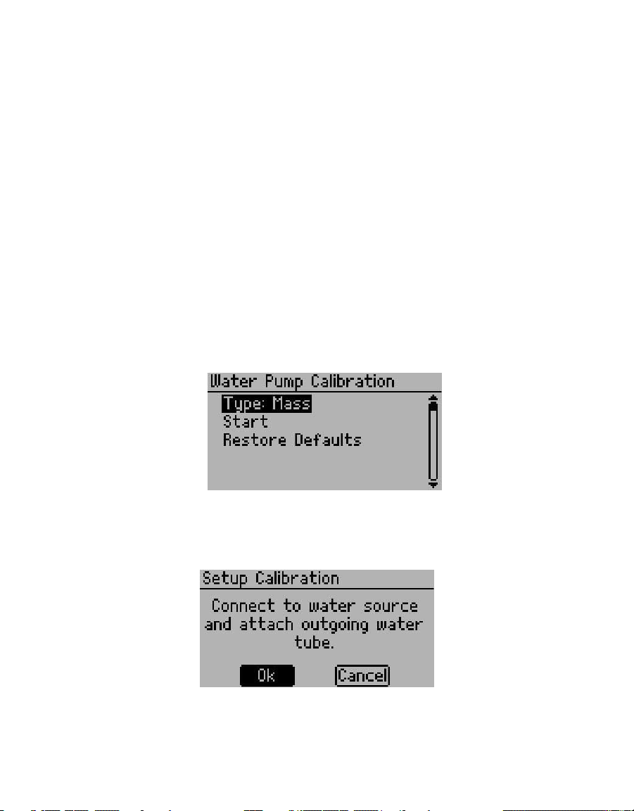
This approach overestimated Kfs due to lateral divergence of flow resulting from the
capillarity of the unsaturated soil and from the ponding in the ring (Bouwer 1986). Attempts
to eliminate flow divergence involved the addition of an outer ring to buffer the flow in the
inner ring (Figure30). However, the double-ring infiltrometer technique was ineffective at
preventing lateral flow from the inner ring (Swartzendruber and Olson 1961a, 1961b).
cylinder
D
d
Figure30 Cross section of a double-ring infiltrometer
cylinder
Water
Mariotte
cylinder
b
Wetting
front
More recent research provides new methods for correcting for lateral flow. Reynolds
and Elrick (1990) presented a new analysis method of steady ponded infiltration into
a single ring, which accounts for soil capillarity, depth of ponding, ring radius (b), and
depth of ring insertion (d) and provides a means for calculating Kfs, matric flux (φm), and
macroscopic capillary length (∝). This analysis is known as the two-ponding head approach
(Reynolds and Elrick 1990).
The two -ponding head approach is the technique used by SATURO, though with some
modifications and simplifications. The easiest equation for this calculation is from
Nimmo et al. (2009). They compute Kfs as shown in Equation 1
K
=
fs
Equation 1
where i (cm/s) is the steady (final) infiltration rate (volume divided by area) and F is a
function that corrects for sorptivity and geometrical effects.
20
Page 25

SATURO
DD
11
mm
+
+
K
D
i
D
i
fs
1
1
2
2
mmD
D
D
D
=
++
=
++
()
K
DD
ii
fs
12
12
D
=
-
-
Nimmo et al. (2009) gives F as shown in Equation 2
=+
F
where
D
is the ponding depth (cm)
d
is the insertion depth of the infiltrometer (cm)
b
is the radius of the infiltrometer (cm)
∆
is the constant for a given infiltrometer geometry; C
C
is 0.993
1
C
is 0.578
2
is the reciprocal of the Gardner ∝, which is a characteristic of the soil and its initial
λ
water content (cm)
In Equation 2, ∆ is simply Equation 36 of Reynolds and Elrick (1990) multiplied by bπ, which
allows Figure2 and Equation 2 to be reconciled with Equation 37 of Reynolds and
Elrick(1990).
For two ponding depths, use Equation 3:
Rearranging one of the right terms to solve for λ in terms of Kfs, substituting this for λ in the
other right term, and simplifying yields
+
Cd Cb
12
=+
d + C2b (cm)
1
D
Equation 2
Equation 3
Equation 4
where
D
is the actual high pressure head
1
D
is the actual low pressure head
2
∆
is 0.993d + 0.578b (cm)
i
is infiltration rate at the high pressure head
1
i
is infiltration rate at the low pressure head
2
For ∆, d is the infiltrometer insertion depth and b is the infiltrometer radius. For the SATURO
5-cm insertion ring, d = 5 cm and b = 7.5 cm, so ∆ = 9.3 cm. For the 10-cm insertion ring,
d=10 cm and b = 7.5 cm, so ∆ = 14.3 cm.
21
Page 26

SYSTEM
The hydraulic conductivity is then multiplied by the difference in quasi-steady state
infiltration rate for the last pressure cycle and divided by the difference in the measured
pressure head from the last pressure cycle.
Equation 4 is equivalent to Equation 41 from Reynolds and Elrick (1990) and removes the
dependence on soil characteristics and initial water content described by λ.
22
Page 27
SATURO
4. SERVICE
This section describes the calibration and maintenance of the SATURO infiltrometer.
Troubleshooting solutions and customer service information are also provided.
4.1 CALIBRATION
The water pump comes factory calibrated and is accurate to within ±5% of the reading at
the time of shipment. However, the water pump and tubing can wear, causing a change in the
volume of water flowing through the pump. Calibrate the pump every 6–12 months to ensure
accurate measurements.
Operators can use two methods, based on either mass or volume, to calibrate the pump.
The mass method is the most accurate, and the volume method is more convenient. Either
method is acceptable for calibration.
Prior to calibration, obtain either a scale accurate to 0.01 g or a 25-mL graduated cylinder, for
the mass or volume method respectively.
Press POWER/MENU, select Configuration, and select Water Pump Calibration (Figure31).
Press Enter on Type to toggle between Mass or Volume, and select Start.
Figure31 Water Pump Calibration screen
A message will prompt to connect to a water source and to attach the outgoing water tube
(Figure32). Connect a source of water to the water input port and press Enter.
Figure32 Setup Calibration screen
Both methods require that the water line is purged of air before running the calibration.
Select Purge. Repeat the process to run water through the tube until water runs clear with no
bubbles (Figure33).
23
Page 28
SERVICE
Figure33 Confirmation screen
If using the mass method, tare the scale with the water tank. If using the volume method,
ensure the graduated cylinder is empty. Select Confirm (Figure34).
Figure34 Prepare Volume Measurement screen
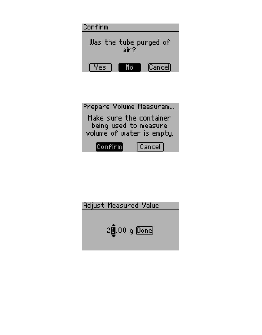
Run the calibration water flow. Compare the reading on the scale or the measurement on the
cylinder to the infiltrometer default value on the Adjust Measured Value screen (Figure35).
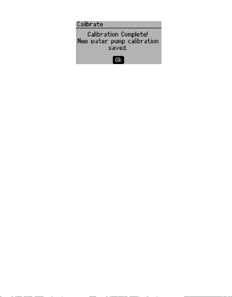
Enter the new value from the scale or cylinder reading, and select Done. This value becomes
the new default water flow value (Figure36). SATURO uses this flow value to measure the
flow of water into the infiltrometer head.
Figure35 Adjust Measured Value screen
24
Page 29
SATURO
Figure36 Calibration Complete screen
To remove the updated calibration values, highlight Restore Defaults on the Water Pump
Calibration screen and press Enter.
Operators may run the calibration sequence as frequently as necessary to verify accurate
readings. Once the calibration is complete, the new value stores in SATURO firmware until
the next new calibration setting.
4.2 MAINTENANCE
Replacement parts can be ordered from METER. Contact Customer Support for more
information. The instrument can be sent in to update tubing, replace battery, inspect system,
and clean instrument. SATURO may also be returned to METER for maintenance and any old or
damaged parts will be replaced as a part of the maintenance program.
NOTE: Complimentary maintenance lasts for 1 year; Customer Support can provide parts and labor cost estimates
after this timeframe. See METER Terms and Conditions (Section 4.5) for more information.
Properly clean the equipment after each use to ensure the longevity of SATURO.
• Remove any soil on the insertion ring to reduce the amount of resistance when installing
the insertion ring.
• Remove soil particles and other materials on the infiltrometer head.
• Wipe down the three tubes with a wet rag.
• Inspect the insertion ring after each use for dents and dings incidental to normal use from
hitting rocks and hard roots. It is important to file away any dents or dings to the bottom
edge of the ring so the inner part of the ring is smooth. Dings and dents protruding towards
the inner portion of the ring can create channels and will allow for preferential flow.
• Purge water from water pump or run dry air through the tubing to dry out the control unit.
• Charge the control unit after each use.
The water pump on the SATURO is a peristaltic pump with a replaceable cartridge that
houses the tube and rollers. The tubing and rollers can wear out over time, typically around
5,000 hours of run time. The pump run time is tracked in the diagnostics screen of SATURO.
25
Page 30

SERVICE
If there is a significant change in pump calibration or the pump begins to become
inconsistent, it may need to be replaced. Contact Customer Support to request instrument
servicing.
SATURO is powered by 12-V, 7-A sealed lead acid battery. Over time, there will be a decrease
in the maximum charge value of the battery. If the battery does not come up to full capacity
after a full charge (typically 4–6 h), it will need to be replaced. Contact Customer Support for
information for a new battery and servicing.
The guidelines in Table 3 may also help identify any potential maintenance problems.
Table 3 Diagnostics screen metrics
Metric Acceptable Ranges/Required Servicing
Water Level Should range from −3.9 to 6.2 cm
Air Pressure Variable; should remain <40 cm
Battery ~11.1 to 13.7 V
Charging Status Variable; recommend beginning test with 100%
Temperature Do not exceed operating temperature; 0–50 °C
Cap Sensor NA
Water Pump Service at 500 h
Cartridge Service at 500 h
Air Pump Service at 500 h
4.3 TROUBLESHOOTING
Table 4 lists common problems and their solutions. If these solutions do not solve the issue,
contact Customer Support.
Table 4 Troubleshooting SATURO
Problem Possible Solutions
SATURO does not turn on
“Firmware is corrupted!
See Manual.”
Test name already exists
Fully charge the battery.
If this does not fix the issue, contact Customer Support.
Check for firmware updates within the SATURO Downloader by
clicking Help > Check for Firmware Updates. Connect SATURO to
the computer and follow the instructions in the updater.
WARNING: Taking this action deletes all data from the unit.
NOTE: METER can extract data from units.
If a new test has the same name as a completed test that is
already stored in memory, then this message will appear.
Rename the test.
26
Page 31

Table 3 Troubleshooting SATURO (continued)
Problem Possible Solutions
Control unit shows low battery
“Data memory is full.”
Test failed to reach the
target water level
Water is leaking between
seal of infiltrometer head
and insertion ring
Selected pressure heads are
not being reached
Infiltrometer does not
maintain pressure
SATURO
Charge the battery to ensure it is fully charged.
NOTE: This error occurs when the battery voltage drops below the
minimum voltage at which the water pump can operate (11.1 V) during a
test and stops the test.
Download the data from the infiltrometer and erase the stored
data on the infiltrometer before performing a new test.
NOTE: The control unit will initially display “Water level warning!” If the
water level remains below the water level sensor (4.3 cm) for more than
10min, SATURO will stop the test and the control unit will display “Water
level error!”
Check that the water supply is connected and water is able to
easily flow from the water supply through the control unit into the
infiltrometer head.
Check for leaks around the seal of the infiltrometer head.
If SATURO is on a slope, the slope may be too great, and the water
level will not reach the sensor.
If there are no apparent leaks, the location may have an
infiltration rate that exceeds the capacity of SATURO. Try
sampling a new location or adding a second water supply to
proceed with themeasurements.
NOTE: Soils with extremely high infiltration rates could cause the water
inside the chamber to remain below 4.3 cm, if the water pump cannot fill
the chamber at a rate greater than the soil’s infiltration rate.
Remove the infiltrometer head and check for debris (grass, leaves,
loose soil, etc.) where the gasket seals with the insertion ring.
Remove any debris and reconnect the infiltrometer head.
Check the tightness of the clamps. The clamps should only apply
enough pressure to slightly compress the gasket. If the clamps
are too tight, they can deform the insertion ring, causing a poor
seal. Adjust the clamp pressure with the screw on top of the
clamps asnecessary.
Check tubing connections to ensure tubes are pressed all the way
into the push-to-connect fittings. The tubes should hit the back of
the fittings.
Check tubing connections to ensure tubes are pressed all the way
into the push-to-connect fittings.
Check the infiltrometer head seals for grass or debris. Verify the
clamps are not bent or deformed. Adjust the clamp screw to the
appropriate tightness to seal the ring as necessary.
NOTE: Tightening the clamp adjustment too tight will deform the metal.
27
Page 32

Table 3 Troubleshooting SATURO (continued)
Problem Possible Solutions
“No depth sensor!”
“Pressure limit exceeded!”
“Temperature too high!”
“Temperature too low!”
Control unit becomes
unresponsive
“Date and time were reset!”
“Missing bootstrap loader!
See Manual.”
SERVICE
Check sensor connection to the control unit.
Verify it is measuring correctly by checking the Water Level value
on the Diagnostics screen.
If these actions do not fix the issue, contact Customer Support.
Check tubing for possible kinks or blockages.
NOTE: This error occurs when the air pressure in the chamber is over
60.0cm or below −50.0 cm and stops the test.
Move the system into a cooler environment. Make sure it is out of
direct sunlight. After the system has cooled, turn the power off
and on again to clear the temperature too high message.
NOTE: This error occurs when the air temperature is above the minimum
operating temperature (50 °C) while a test is running and stops the test
when this occurs.
Move the system into a warmer environment. After the system has
warmed, turn the power off and on again to clear the temperature
too low message.
NOTE: This error occurs when the air temperature is below the minimum
operating temperature (0 °C) while a test is running. Water frozen in the
system could cause damage. The error will stop the test.
Charge the battery.
Press and hold the BACK button for more than 7 s to restart.
If these actions do not fix the issue, contact Customer Support.
Ensure the battery is fully charged and update the date and time
in the Settings menu.
If this action does not fix the issue, contact Customer Support.
This error means firmware updates will not be possible on this
instrument unless the instrument is serviced by Customer
Support.
The instrument may be used without consequences, but contact
Customer Support for servicing so the instrument firmware can
stay up to date with the latest features and bug fixes.
28
Page 33

SATURO
4.4 CUSTOMER SUPPORT
Customer service representatives are available for questions, problems, or feedback Monday
through Friday, 8 am–5 pm Pacific time.
Phone: +1.509.332.5600
Fax: +1.509.332.5158
Website: metergroup.com
If contacting METER by email or fax, please include the following information:
Name
Address
Phone
NOTE: For SATURO Infiltrometers purchased through a distributor, please contact the distributor directly for assistance.
Email address
Instrument serial number
Description of the problem
4.5 TERMS AND CONDITIONS
CONTRACT FORMATION. All requests for goods and/or services by METER Group, Inc. USA
(METER) are subject to the customer’s acceptance of these Terms and Conditions. The
Buyer will be deemed to have irrevocably accepted these Terms and Conditions of Sale
upon the first to occur of the Buyer’s issuance of a purchase order or request for goods or
services. Unless expressly assented to in writing by METER, terms and conditions different
are expressly rejected. No course of dealing between the parties hereto shall be deemed to
affect or to modify, amend or discharge any provisions of this agreement.
PRICES AND PAYMENT. Invoice prices will be based upon METER prices as quoted or at
METER list price in effect at the time an order is received by the Seller. Prices do not include
any state or federal taxes, duties, fees, or charges now or hereafter enacted applicable to the
goods or to this transaction, all of which are the responsibility of the Buyer. Unless otherwise
specified on the invoice, all accounts are due and payable 30 days from the date of invoice.
Unpaid accounts extending beyond 30 days will be subject to a service charge of 2% per
month (24% per annum). Should Seller initiate any legal action or proceeding to collect on
any unpaid invoice, Seller shall be entitled to recover from Buyer all costs and expenses
incurred in connection therewith, including court costs and reasonable attorney’s fees.
RISK OF LOSS AND DELIVERY TITLE. Liability for loss or damage passes to the Buyer when
the Seller delivers the goods on the Seller’s dock or to the transporting agent, whichever
occurs first. The Seller has the right to deliver the goods in installments. Shipping and
delivery dates communicated by the Seller to the Buyer are approximate only.
SHIPMENT. In the absence of specific shipping instructions, the Seller, if and as requested
by the Buyer, will ship the goods by the method the Seller deems most advantageous. Where
the Seller ships the goods, the Buyer will pay all transportation charges that are payable on
29
Page 34

SERVICE
delivery or, if transportation charges are prepaid by the Seller, the Buyer will reimburse the
Seller upon receipt of an invoice from the Seller. The Buyer is obligated to obtain insurance
against damage to the goods being shipped. Unless otherwise specified, the goods will be
shipped in the standard Seller commercial packaging. When special packing is required or, in
the opinion of the Seller, required under the circumstances, the cost of the special packaging
shall be the responsibility of the Buyer.
INSPECTION AND ACCEPTANCE. Goods will be conclusively deemed accepted by the Buyer
unless a written notice setting out the rejected goods and the reason for the rejection is
sent by the Buyer to the Seller within 10 days of delivery of the goods. The Buyer will place
rejected goods in safe storage at a reasonably accessible location for inspection by the
Seller.
CUSTOM GOODS. There is no refund or return for custom or nonstandard goods.
WARRANTIES. The Seller warrants all equipment manufactured by it to be free from defects
in parts and labor for a period of one year from the date of shipment from factory. The liability
of the Seller applies solely to repairing, replacing, or issuing credit (at the Seller’s sole
discretion) for any equipment manufactured by the seller and returned by the Buyer during
the warranty period. SELLER MAKES NO SEPARATE OR OTHER WARRANTY OF ANY NATURE
WHATSOEVER, EXPRESS OR IMPLIED, INCLUDING THE WARRANTY OF MERCHANTABILITY
OR FOR A PARTICULAR PURPOSE. There shall be no other obligations either expressed or
implied.
LIMITATION OF LIABILITY. Seller will not be liable to the Buyer or any other person or entity
for indirect special, incidental,consequential, punitive, or exemplary damages in connection
with this transaction or any acts or omissions associated therewith or relating to the sale
or use of any goods, whether such claim is based on breach of warranty, contract, tort, or
other legal theory and regardless of the causes of such loss or damages or whether any other
remedy provided herein fails. In no event will the Seller’s total liability under this contract
exceed an amount equal to the total amount paid for the goods purchased hereunder.
WAIVER. In the event of any default under or breach of the contract by the Buyer, the Seller
has the right to refuse to make further shipments. The Seller’s failure to enforce at any time
or for any period of time the provisions of this contract will not constitute a waiver of such
provisions or the right of the Seller to enforce each and every provision.
GOVERNING LAW. The validity, construction, and performance of the contract and the
transactions to which it relates will be governed by the laws of the United States of America.
All actions, claims, or legal proceedings in any way pertaining to this contract will be
commenced and maintained in the courts of Whitman County, State of Washington, and the
parties hereto each agree to submit themselves to the jurisdiction of such court.
SEVERABILITY. If any of the Terms and Conditions set out in this contact are declared
to be invalid by a court, agency, commission, or other entity having jurisdiction over the
interpretation and enforcement of this contract, the applications of such provisions to
parties or circumstances other than those as to which it is held invalid or unenforceable
30
Page 35

SATURO
will not be affected. Each term not so declared invalid or unenforceable will be valid and
enforced to the fullest extent permitted by law and the rights and obligations of the parties
will be construed and enforced as though a valid commercially reasonable term consistent
with the undertaking of the parties under the order has been substituted in place of the
invalid provision.
SET-OFF. The Buyer may not set-off any amount owing from the Seller to the Buyer against
any amount payable by the Buyer to the Seller whether or not related to this contract.
31
Page 36

SERVICE
REFERENCES
Bouwer H. 1986. Intake rate: Cylinder infiltrometer. In Klute A., editor, Methods of soil
analysis: Part 1—Physical and Mineralogical Methods. 2nd ed. Madison (WI): ASA and
SSSA. 825−844.
Dane JH and Topp GC, editors. 2002. Methods of soil analysis: Part 4—Physical Methods.
Madison (WI): Soil Science Society of America Inc.
Daniel DE. 1989. In situ hydraulic conductivity tests for compacted clay. J. Geotech. Eng. 115(9).
Nimmo JR, Schmidt KM, Perkins KS, and Stock JD. 2009. Rapid measurement of field-
saturated hydraulic conductivity for areal characterization. Vadose Zone J. 8(1): 142−149.
Reynolds WD and Elrick DE. 1990. Ponded infiltration from a single ring: I. Analysis of steady
flow. Soil Sci. Soc. Am. J. 54(5): 1233−1241.
Swartzendruber D and Olson TC. 1961. Sand-model study of buffer effects in the double-ring
infiltrometer. Soil Sci. Soc. Am. Proc. 25(1): 5−8.
Swartzendruber D and Olson TC. 1961. Model study of the double ring infiltrometer as
affected by depth of wetting and particle size. Soil Sci. 92(4): 219−225.
32
Page 37

INDEX
C
calibration 23–25
components
charger 9, 11
control unit 11
depth sensor 18
infiltrometer head 18
insertion ring 17
USB port 11
water supply tank 18–19
connections 12
contents. Seecomponents
customer support 29–33
F
field saturated hydraulic conductivity 1,
19–23
I
infiltration rate 5
installation 2
K
Kfs 1, 9, 19–23
L
lateral flow 20
M
maintenance
battery 26
cleaning 25–26
infiltrometer head 25
insertion ring 25
water pump 25
P
ponding depths 21
Q
R
references 32
running a test
downloading 7–8
starting 6
stopping 7
S
SATURO Downloader 7–8
screen
about 17
contrast 16
date 15
diagnostics 16
flux 13
pressure 13
results 14
status 13
time 15
units 15
water level 14–15
water pump calibration 14
service. Seemaintenance
settings
hold time 5
pressure 4
pressure cycles 5
soak time 5–6
setup. Seemaintenance
sorptivity 20
specifications 9
T
tab
Configuration 14–17
Data 17
Reading 13–14
terms and conditions 29–33
theory 19–22
troubleshooting 26–33
quasi-steady state 5, 22
33
Page 38

14967-02
12.29.2017
METER Group, Inc. USA
2365 NE Hopkins Court
T: +1.509.332.5600 F: +1.509.332.5158
Pullman, WA 99163
W: metergroup.com
© 2017 All Rights Reserved.
Page 39

 Loading...