

Page 1
1151691311 - 0206
SPA 1702
Gebruiksaanwijzing . . . . . . .bladzijde 23
Istruzioni d’uso . . . . . . . . . . . .pagina 29
Manual de usuario . . . . . . . . .página 35
Bruksanvisning . . . . . . . . . . . . .sidan 41
Bruksanvisning . . . . . . . . . . . . .Side 47
Betjeningsvejledning . . . . . . . . .Side 53
Notice d’utilisation . . . . . . . . . . .page 17
Operating Instructions . . . . . . . .page 11
Betriebsanleitung . . . . . . . . . . .Seite 5
Page 2
263
Page 3

1
3
4
6
10
15
16
8
9
12
5
11
13
14
Page 4

4
Weiteres Zubehör siehe auch metabo Hauptkatalog.
For other accessories, refer also to metabo’s General Catalogue.
Vous trouverez d’autres accessoires dans le catalogue principal metabo.
Voor nog meer toebehoren zie ook de metabo catalogus.
Per altri accessori vedere anche il catalogo principale metabo.
Para más información sobre accesorios, véase el catálogo general de metabo.
Vill du ha fler tillbehör, se även metabos huvudkatalog.
Annet tilbehør, se også metabos hovedkatalog.
Se også metabo-hovedkataloget for yderligere tilbehør.
Page 5

5
Inhaltsverzeichnis
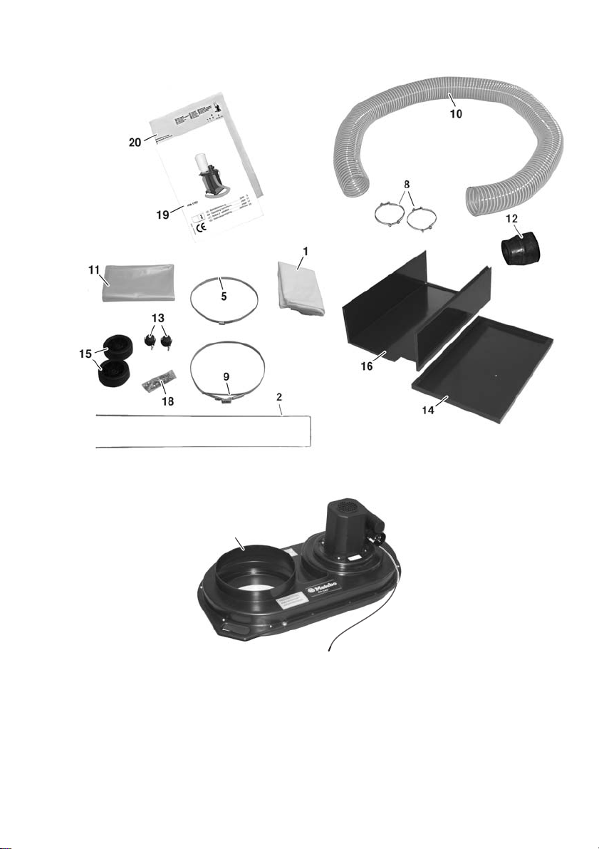
Bild Lieferumfang (Seite 2)
Bild Geräteelemente (Seite 3)
Bild Zubehörübersicht (Seite 4)
1 Netzspannung / Best.-Nr.
2 Lieferumfang
3 Geräteelemente
4 Sicherheitshinweise
5 Bestimmungsgemäße Verwendung
6 Montage
6.1 Unterbau
6.2 Lenkrollen und Räder
6.3 Saugaggregat
6.4 Filter, Filterhaltebügel und Spänesack
6.5 Saugschlauch
7 Inbetriebnahme
8 Wartung
9 Zubehör
10 Reparatur
11 Umweltschutz
12 Technische Daten
1 Netzspannung / Best.-Nr.
Vergleichen Sie vor Inbetriebnahme, ob die auf
dem Typenschild angegebene Netzspannung
und Netzfrequenz mit den Daten Ihres
Stromnetzes übereinstimmen (siehe Seite 10).
2 Lieferumfang
1) Filter (Kategorie „G“)
2) Filterhaltebügel
5) Spannband für Filter
6) Saugaggregat
8) Schlauchklemme (2 Stück)
9) Spannband für Spänesack
10) Saugschlauch Ø 100 mm, Länge 2,5 m
11) Spänesack
12) Anschlussstutzen
13) Lenkrolle (2 Stück)
14) Bodenplatte
15) Rad Ø 125 mm (2 Stück)
16) Säule
18) Kleinteilesatz für Montage
19) Betriebsanleitung
20) Ersatzteilliste
Kleinteile (im Beutel):
Innensechskantschraube M6x16 9 Stück
Sechskantschraube M8x60 2 Stück
Sechskantmutter M6 9 Stück
Sechskantmutter M8 6 Stück
Scheibe 6,4 9 Stück
Scheibe 8,4 12 Stück
Betriebsanleitung
Sehr geehrter Kunde,
vielen Dank für das Vertrauen, das Sie uns beim Kauf Ihres neuen metabo Absauggerätes
entgegengebracht haben. Jede metabo Maschine wird sorgfältig getestet und unterliegt den
strengen Qualitätskontrollen der metabo Qualitätssicherung. Die Lebensdauer einer Maschine
hängt aber in starkem Maße von Ihnen ab. Beachten Sie bitte die Informationen dieser
Betriebsanleitung und der beiliegenden Dokumente. Je sorgsamer Sie Ihre metabo Maschine
behandeln, umso länger wird sie zuverlässig ihren Dienst erfüllen.
DEUTSCH
Page 6
3 Geräteelemente
1) Filter
3) Elektromotor 750 W
4) Schalter-Steckerkombination
5) Spannband für Filter
6) Saugaggregat
8) Schlauchklemme
9) Spannband für Spänesack
10) Saugschlauch
11) Spänesack
12) Anschlussstutzen
13) Lenkrolle
14) Bodenplatte
15) Rad
16) Säule
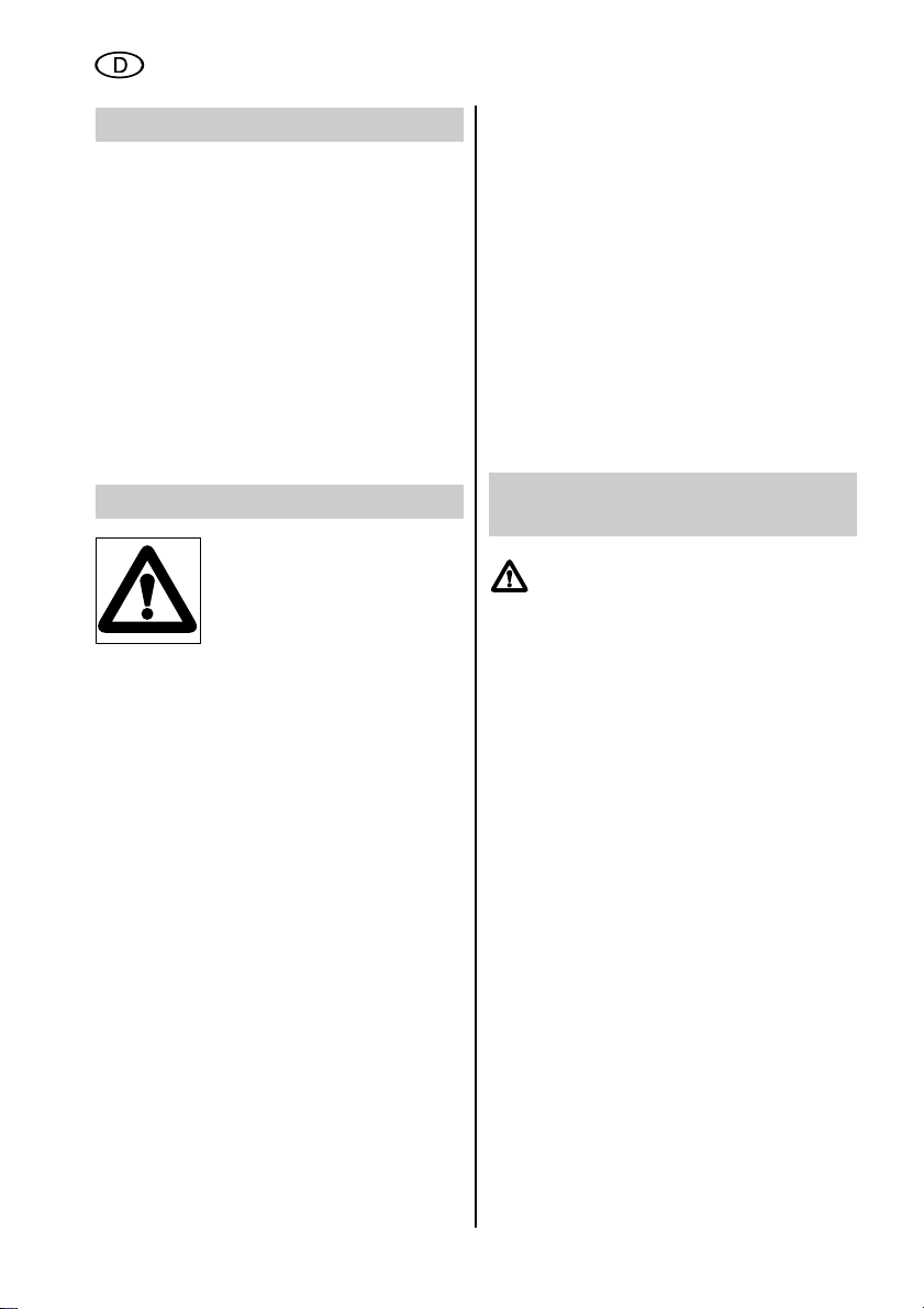
4 Sicherheitshinweise
Lesen Sie diese Betriebsanleitung aufmerksam und
vollständig durch.
– Das Gerät darf nur im komplett montierten
Zustand eingeschaltet werden.
– Absaugbetrieb nur bei angeschlossenen
Werkzeugmaschinen oder angeschlossener
Reinigungsdüse.
– Feste Körper, z.B. Holzstücke (Kantenlänge
größer als 10 mm), Metallteile und Steine
etc., dürfen nicht abgesaugt werden.
Solche Körper führen zur Beschädigung
des Ventilatorflügelrades oder des Saugaggregates (Ausschluss von Garantieleistungen).
– Wartungsarbeiten, z.B. Sack-, Filter- und
Schlauchwechsel, sind nur bei abgezogenem Netzstecker vorzunehmen. Es besteht
sonst Verletzungsgefahr durch Zugriff auf
das Ventilatorflügelrad.
– Gerät vor Nässe schützen, keine Flüssig-
keiten absaugen!
– Nicht in explosionsgefährdeten Räumen
betreiben.
– Vor jeder Inbetriebnahme ist das Gerät auf
einwandfreie Funktion zu überprüfen.
– Gerät nicht bei Temperaturen unter 0 °C
verwenden. Kein Sauggut absaugen, das
eine Temperatur höher als 60 °C hat.
– Kinder oder Personen, die mit dem
Absauggerät nicht vertraut sind, dürfen es
nicht benutzen.
– Unfallverhütungs- und Brandschutz-
vorschriften beachten.
– Beim Wechsel des Filters (1) oder des
Spänesackes (11) ist eine Staubschutzmaske (Filtermaske mit Partikelfilter,
Filterklasse 2) zu tragen.
– Vor Austausch des Spänesackes (11) ist
der Filter (1) zu reinigen (abzuklopfen).
– Im Bedarfsfall dürfen nur Originalzube-
hörteile verwendet werden. Der Benutzer
verliert alle eventuell bestehenden
Ansprüche, wenn er das Absauggerät mit
anderen als den Originalteilen ausstattet.
5 Bestimmungsgemäße
Verwendung
Das Absauggerät dient zum
Absaugen von Holzspänen mit
geringem Holzstaubanteil, wie sie bei
Arbeiten mit Holzbearbeitungsmaschinen (z.B. Tischkreissägen,
Bandsägemaschinen, Abricht- und
Dickenhobelmaschinen und
Tischfräsmaschinen) anfallen.
Zum Aufsaugen von Flüssigkeiten ist das Gerät
nicht geeignet. Nicht aufgesaugt werden dürfen
außerdem: scharfkantige und spitze Gegenstände (wie z.B. Glasscherben oder Nägel)
sowie Material, das wärmer als 60 °C ist.
Für Schäden durch nicht bestimmungsgemäßen Gebrauch des Absauggerätes haftet
allein der Benutzer. Allgemein anerkannte
Unfallverhütungsvorschriften und die „Sicherheitshinweise“ müssen beachtet werden.
Das Absauggerät ist zur nichtgewerblichen
Nutzung bestimmt. Eine nichtgewerbliche
Nutzung ist gegeben, wenn keine Arbeitnehmer, keine Personen in Berufsausbildung,
in Schulen, in Heimarbeit und keine Personen
in einem arbeitsähnlichen Beschäftigungsverhältnis das Absauggerät benutzen.
6
DEUTSCH
Page 7

6 Montage
6.1 Unterbau
Säule (16) mit Aussparung nach unten aufstellen. Bodenplatte (14) auflegen und mit
5 Innensechskantschrauben M6x16, Scheiben
6,4 und Sechskantmuttern M6 lt. Abbildung
befestigen. Zum Befestigen der Schraubverbindungen verwenden Sie einen Steckschlüssel SW 10 mm und einen Schraubendreher für
Innensechskantschrauben SW 4 mm.
6.2 Lenkrollen und Räder
Scheibe 8,4 auf Gewindestift an der Lenkrolle
(13) setzen. Lenkrolle (13) mit Scheibe in
vorhandene Bohrungen an der Bodenplatte
(14) einstecken. Scheibe 8,4 und Sechskantmutter M8 aufsetzen. Sechskantmutter mit
Maulschlüssel SW 13 mm festdrehen.
Dabei Lenkrolle mit zweitem Maulschlüssel
SW 13 mm festhalten.
Rad (15) mit zwei Scheiben 8,4 auf
Sechskantschraube M8x60 aufstecken und
Sechskantmutter M8 so befestigen, dass sich
das Rad (15) zwischen den Scheiben auf der
Sechskantschraube leicht drehen lässt.
Scheibe 8,4 auf die Sechskantschrauben mit
vormontierten Rad (15) setzen. Sechskantschraube durch die seitlichen Bohrungen in
der Bodenplatte (14) stecken und mit
Scheibe 8,4 und Sechskantmutter M8
befestigen. Blende lt. Abbildung auf das Rad
aufdrücken, bis sie hörbar einrastet.
6.3 Saugaggregat
Säule (16) mit Bodenplatte auf die Laufräder
stellen. Saugaggregat (6) auf die Säule (16)
auflegen und ausrichten. 4 Innensechskantschrauben M6x16 oben durch die vorhandenen
Bohrungen stecken und mit Schraubendreher
SW 4 mm befestigen.
7
DEUTSCH
14
16
13
15
14
15 15
6
13
13
14
16
Page 8
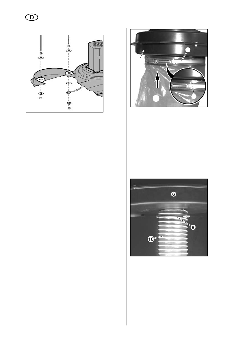
6.4 Filter, Filterhaltebügel und Spänesack
Sechskantmuttern M6 bis in die Mitte der
Gewinde am Filterhaltebügel (2) aufdrehen.
Scheiben 6,4 aufstecken und Filterhaltebügel
(2) in die vorhandenen Bohrungen am
Saugaggregat (6) einstecken.
Scheibe 6,4, Erdungslitze, Fächerscheibe
gemäß Abbildung mit Sechskantmutter M6 am
Filterhaltebügel (2) befestigen. Sechskantmutter M6 festziehen.
Auf die andere Seite des Filterhaltebügels (2)
Scheibe 6,4 mit Sechskantmutter M6
aufschrauben und festziehen.
Filter (1) über den Filterhaltebügel (2) stülpen.
Spannband über den Filter (1) schieben. Filter
(1) mit Spannband über den Stutzen am
Saugaggregat (6) stülpen. Darauf achten, dass
sich der Filter (1) rundherum über dem Stutzen
am Saugaggregat (6) und unter dem Spannband befindet. Spannband mit Schraubendreher befestigen.
Spannband (9) über den Spänesack (11)
schieben. Spannband mit Sack auf den
Stutzen an der Unterseite des Saugaggregates
(6) stülpen. Darauf achten, dass sich der
Spänesack (11) rundherum über dem Stutzen
am Saugaggregat (6) und unter dem Spannband befindet. Spannband so ausrichten, dass
es rundherum auf dem grauen Schaumstoffstreifen aufliegt. Spannband (9) durch
Umlegen des Verschlusshebels befestigen.
6.5 Saugschlauch
Schlauchklemme (8) auf den Saugschlauch
(10) stecken. Saugschlauch (10) auf den
kleinen Stutzen am Saugaggregat (6) stecken.
Darauf achten, dass der Saugschlauch (10)
rundherum aufliegt. Saugschlauch mit
Schlauchklemme (8) befestigen.
8
DEUTSCH
9
6
11
9
Page 9

Anschlussstutzen (12) in den Saugschlauch
(10) stecken und durch Festziehen der
Schlauchklemme fixieren.
Den Saugschlauch (10) auf den Absaugstutzen
der Holzbearbeitungsmaschine stecken.
7 Inbetriebnahme
Zum Betreiben des Absauggerätes wird eine
Netzspannung von 230 V ~ 50 Hz benötigt und
ein geeignetes Verlängerungskabel mit
Schutzleiter (dreiadrig). Das Absauggerät darf
nur an vorschriftsmäßig geerdeten Steckdosen
angeschlossen werden.
Vor Inbetriebnahme des Absauggerätes muss
der Saugschlauch an die Holzbearbeitungsmaschine vorschriftsmäßig angeschlossen
werden.
Verlängerungskabel auf den Stecker der
Schalter-Steckerkombination (4) stecken.
Schalter in Stellung Absauggerät
0 ausgeschaltet
I eingeschaltet
8 Wartung
Vor allen Wartungsarbeiten: Stecker aus der
Steckdose ziehen! Bei nachlassender Saugleistung und vor jedem Spänesackwechsel
muss der Filter (1) von Hand durch Rütteln
gereinigt werden. Dies lässt den feinen
Holzstaub, der sich im Gewebe des Filters (1)
angesammelt hat, in den Spänesack (11)
fallen, und die Luftdurchlässigkeit des
Filters (1) bleibt erhalten. Das Reinigen des
Filters (1) geschieht immer bei Gerätestillstand
und ohne Filterdemontage. Den Spänesack
erst abnehmen, nachdem sich der Staub
abgesetzt hat und das Ventilatorflügelrad
stillsteht.
Zusätzlich ist mindestens einmal monatlich
durch eine unterwiesene Person eine staubtechnische Überprüfung durchzuführen auf:
– Beschädigung des Filters (1)
– Dichtigkeit des Gehäuses und der
Dichtung für den Spänesack (11)
– Einwandfreier Zustand der elektrischen
Ausrüstung (Schalter-Steckerkombination (4), Verlängerungskabel).
Beschädigte Filter (1) und Spänesäcke (11)
dürfen keinesfalls weiterverwendet werden!
9 Zubehör
Metabo bietet ein umfangreiches
Programm an Absauggerät-Zubehör. Für den
optimalen Einsatz Ihrer Maschine setzen Sie
deshalb nur metabo-Zubehör ein. Eine
Übersicht finden Sie auf der Seite 4 sowie im
metabo-Gesamtkatalog.
9
DEUTSCH
4
Page 10

10 Reparatur
Reparaturen an metabo Elektrogeräten dürfen nur durch eine
Elektrofachkraft ausgeführt werden!
Reparaturbedürftige metabo Elektrogeräte
können an die auf der Ersatzteilliste angegebenen Adressen eingesandt werden.
Bitte beschreiben Sie bei der Einsendung zur
Reparatur den festgestellten Fehler.
Änderungen im Sinne des technischen
Fortschritts vorbehalten.
11 Umweltschutz
metabo-Verpackungen sind 100% recyclingfähig. Sie gehören nicht auf den Müll. So
können Verpackungen wieder in den
Rohstoffkreislauf einfließen.
Ausgediente Elektrogeräte und Zubehör
enthalten große Mengen wertvoller Roh- und
Kunststoffe, die ebenfalls einem Recyclingprozess zugeführt werden können. Deshalb
gehören Elektrogeräte und Zubehör nicht in
den Müll, sondern sollten einer umweltfreundlichen Wiederverwertung zugeführt
werden.
12 Technische Daten
Absauggerät SPA 1702
Bestell-Nr. 013 017 0100
Leistung 750 Watt
Spannung/Frequenz 230 V ~ 50 Hz
Nennvolumenstrom V
nenn
633 m
3
/h
Max. Volumenstrom V
max
1010 m3/h
Nenn.-Unterdruck 920 Pa
Max.-Unterdruck 1730 Pa
Filterfläche 1,08 m
2
Filter (Material) Kategorie „G“
Schlauchnennweite 100 mm
Schlauchlänge 2,5 m
Spänesackvolumen 90 l
Geräusch nach
EN 23744
(Schalldruckpegel) 81 dB(A)
Abmessungen
(L x B x H) 882 x 562 x 1671 mm
Gewicht 24 kg
10
DEUTSCH
Page 11
11
Contents
Illustration: Parts Supplied (Page 2)
Illustration: Appliance Components (Page 3)
Illustration: Overview of Accessories (Page 4)
1 Mains Voltage / Order No.
2 Parts Supplied
3 Appliance Components
4 Safety Instructions
5 Proper Use
6 Assembly
6.1 Base
6.2 Castors and wheels
6.3 Suction unit
6.4 Filter, filter retaining clip and chip bag
6.5 Suction hose
7 Initial Use
8 Maintenance
9 Accessories
10 Repairs
11 Environmental Protection
12 Technical Specifications
1 Mains Voltage / Order No.
Before initial use, check that the mains voltage
and mains frequency stated on the model plate
match the figures for your own mains supply
(refer to page 16).
2 Parts Supplied
1) Filter (Category “G”)
2) Filter retaining clips
5) Filter clamping band
6) Suction unit
8) Hose clamp (2 pcs.)
9) Chip bag clamping band
10) 100 mm Ø suction hose, 2.5 m long
11) Chip bag
12) Connector
13) Castors (2 pce.)
14) Base-plate
15) 125 mm Ø wheels (2 pce.)
16) Column
18) Set of sundry assembly parts
19) Operating Instructions
20) List of Spare Parts
Sundry parts (in bag):
M6x16 hexagonal socket-head screws 9 pce.
M8x60 hexagonal-head screws 2 pce.
M6 hexagonal nuts 9 pce.
M8 hexagonal nuts 6 pce.
6.4 washers 9 pce.
8.4 washers 12 pce.
Operating Instructions
Dear Customer,
Thank you for the trust you have placed in us by buying a metabo dust extractor. Every metabo
machine is carefully tested and subjected to stringent quality control procedures by the metabo
quality assurance department. Nevertheless, the service life of a machine depends to a great
extent on you. Please read the information in these operating instructions and the accompanying
documents. The greater the care with which you handle your metabo machine, the longer it will
provide a reliable service to you.
ENGLISH
Page 12
3 Appliance Components
1) Filter
3) 750 watt electric motor
4) Combined switch/plug
5) Filter clamping band
6) Suction unit
8) Hose clamp
9) Chip bag clamping band
10) Suction hose
11) Chip bag
12) Connector
13) Castor
14) Base-plate
15) Wheel
16) Column
4 Safety Instructions
Read through these Operating
Instructions carefully and
thoroughly.
– The appliance must not be switched on until
it has been completely assembled.
– Extractor should only be operated if the
machine tools or cleaning nozzle are
connected.
– Solid bodies, e.g. pieces of wood (edge
longer than 10 mm), metal scraps and
stones etc. must not be vacuumed up.
Materials of this kind cause damage to the
fan impeller or the suction unit (rendering
guarantee claims null and void).
– Always disconnect the plug from the mains
supply before undertaking any maintenance
tasks, e.g. changing the bag, filter or hose,
so as to exclude any possibility of injury
caused by coming into contact with the
moving fan impeller.
– Keep the appliance dry. Do not vacuum up
any liquids.
– Do not use in any space where there is a
risk of explosion.
– Always check that the appliance is
operating properly before use.
– Do not use the appliance at temperatures
less than 0 °C. Do not vacuum up any
material which is at a temperature above
60 °C.
– The appliance must not be used by children
or any person who is not familiar with its
operation.
– Observe accident prevention and fire
prevention regulations.
– When changing the filter (1) or the chip bag
(11), a face-mask (filter-mask with particle
filter, filter class 2) must be worn to provide
protection from dust.
– Before changing the chip bag (11), tap the
filter (1) to dislodge deposits and clean.
– Where accessories are to be used, these
must be original manufacturer’s parts only.
The operator will render null and void any
claims arising if he uses the chip extractor
with anything other than original parts.
5 Proper Use
The chip extractor is designed for
extracting wood chips with a low
proportion of sawdust in connection
with wood-processing machines
(e.g. circular sawing machines, band
sawing machines, surface planing
and thicknessing machines and
vertical spindle moulding machines)
where these produce wood chips.
The appliance is not designed for vacuuming
up liquids. In addition, it should not be used for
the following materials: sharp-edged and
pointed objects (such as broken glass or nails)
or any material at a temperature above 60 °C.
The operator bears sole responsibility for any
damage caused by inappropriate use. The
generally recognised accident prevention
regulations and the “Safety Instructions” must
be observed.
The chip extractor is designed for noncommercial use. Non-commercial use means
that the appliance is not used by employees,
persons undergoing professional training, in
schools, for domestic purposes, or by persons
in an employment relationship representing the
equivalent of work.
12
ENGLISH
Page 13
6 Assembly
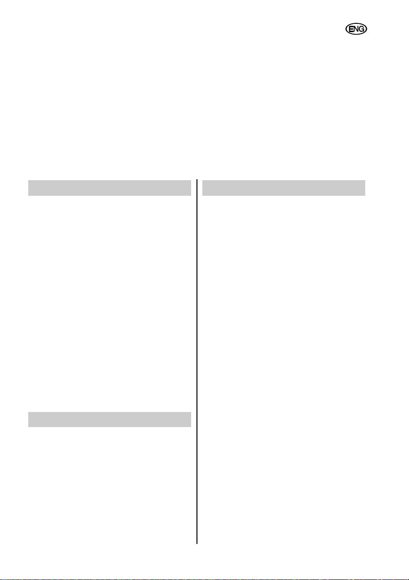
6.1 Base
Set up the column (16) with the recess down.
Position the base-plate (14) and secure with
5 M6x16 hexagonal socket-head screws,
6.4 washers and M6 hexagonal nuts as
illustrated. To tighten threaded connections,
use a 10 mm AF box spanner and a 4 mm AF
Allen key for hexagonal socket-head screws.
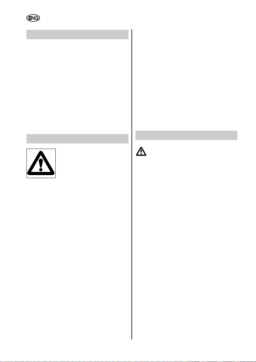
6.2 Castors and wheels
Locate 8.4 washer on the grub screw on the
castor (13). Push castor (13) with its washer
fitted into the holes drilled for the purpose in
the base-plate (14).
Fit 8.4 washer and M8 hexagonal nut. Tighten
hexagonal nut with a 13 mm AF open-ended
spanner while holding the castor in position
with a second 13 mm AF spanner.
Fit wheel (15) with two 8.4 washers to the
M8x60 hexagonal-head screw and tighten the
M8 hexagonal nut so that the wheel (15) turns
easily in its location between the washers on
the hexagonal-head screw. Fit the 8.4 washer
onto the hexagonal-head screws with the
wheel (15) fitted in place. Insert the hexagonalhead screw through the lateral holes drilled in
the base-plate (14) and secure with the
8.4 washer and M8 hexagonal nut. Press the
cover into place on the wheel until it can be
heard clicking into place (see illustration).
6.3 Suction unit
Locate the column (16) with base-plate on the
wheels. Place the suction unit (6) on the
column (16) and align. Insert 4 M6x16
hexagonal socket-head screws through the
holes drilled for the purpose at the top and
tighten with a 4 mm AF Allen key.
13
ENGLISH
14
16
13
15
14
15 15
6
13
13
14
16
Page 14

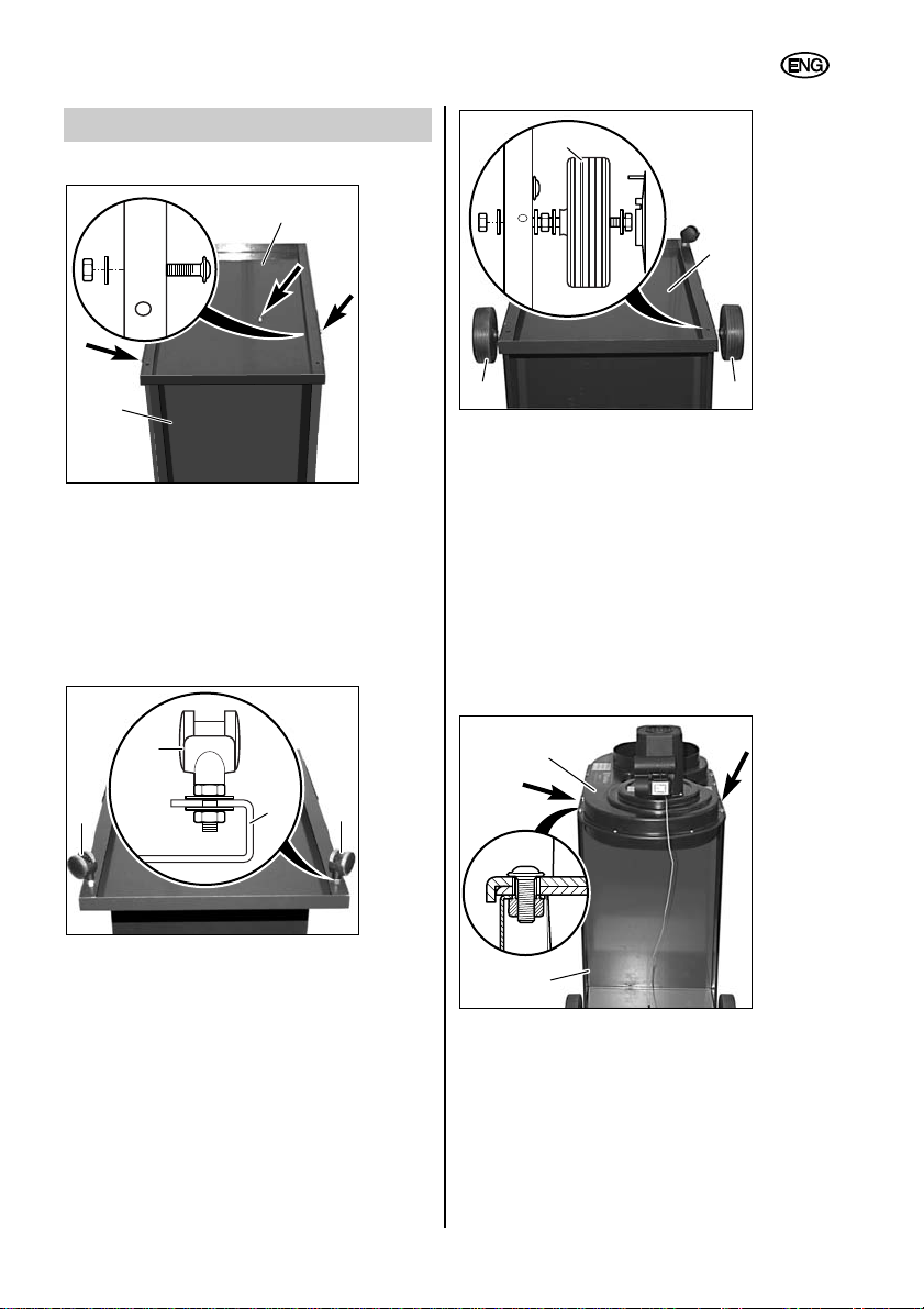
6.4 Filter, filter retaining clip and dust bag
Screw M6 hexagon nuts into the filter retaining
clip (2) halfway up the thread. Push on
washers 6,4 and insert filter retaining clip (2)
into the holes provided on the extractor (6).
Secure washer 6,4, stranded earth wire and
serrated lock washer to the filter retaining clip
(2) with M6 hexagon nuts, as shown in the
illustration. Tighten M6 hexagon nuts.
Screw on washer 6,4 with M6 hexagon nut on
the other side of the filter retaining clip (2) and
tighten.
Push the filter (1) over the filter retaining clip
(2). Push tension band over the filter (1). Push
the filter (1) with tension band over the
connector on the extractor assembly (6). Make
sure that the filter (1) is over the extractor
connector (6) all the way round and is
positioned under the tension band. Secure the
tension band with a screwdriver.
Push tension band (9) over the dust bag (11).
Push tension band with bag over the connector
on the underside of the extractor assembly (6).
Make sure that the dust bag (11) is over the
extractor connector (6) all the way round, and
is positioned under the tension band. Align
tension band so that it is positioned on the
foam strip all the way round. Secure the
tension band (9) by folding over the locking
lever.
6.5 Suction hose
Push the hose clamp (8) over the suction hose
(10). Push the suction hose (10) onto the small
connector on the extractor assembly (6). Make
sure that the suction hose (10) is positioned
correctly all the way round. Secure the suction
hose with the hose clamp (8).
14
ENGLISH
9
6
11
9
Page 15
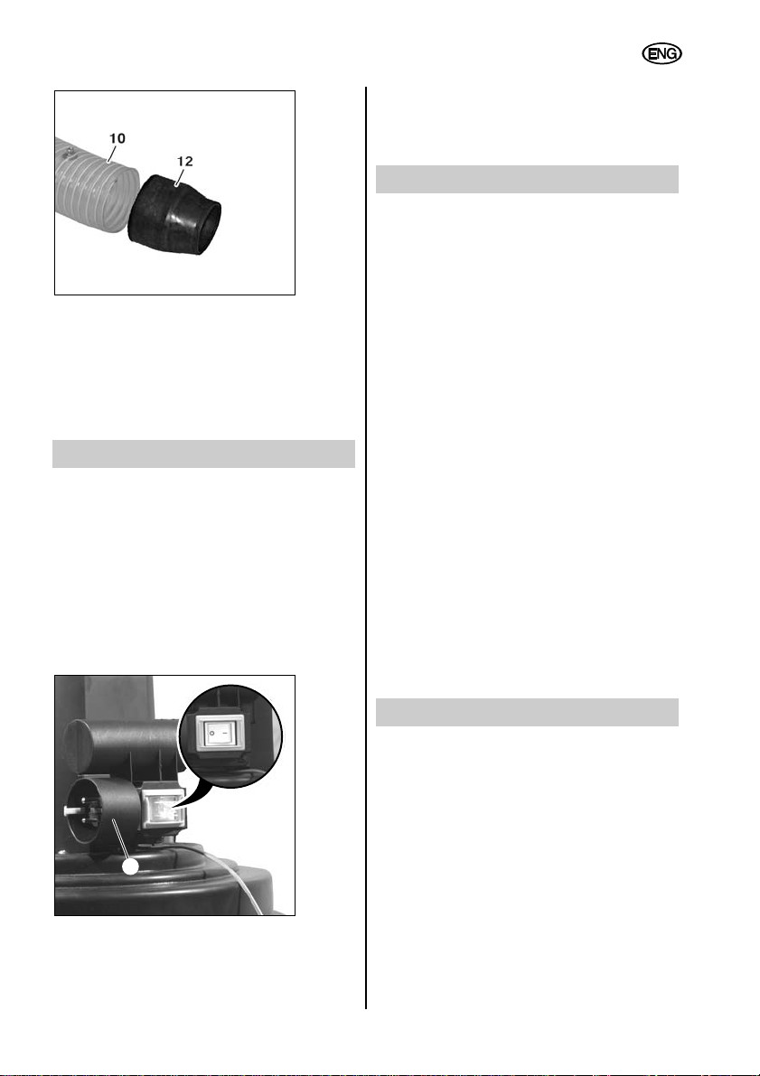
Push the connector (12) into the suction hose
(10) and tighten the hose clamp to secure.
Push the suction hose (10) onto the extractor
connection piece on the wood-processing
machine.
7 Initial Use
For operation, the chip extractor re-quires a
mains voltage of 230 V ~ 50 Hz and a suitable
extension cable with an earth conductor
(three-core). The chip extractor may only be
connected to sockets which have been earthed
in compliance with regulations.
Before putting the chip extractor into use, the
suction hose must be connected to the woodprocessing machine as per instructions.
Fit the extension cable to the plug in the
combined switch-plug fitting (4).
Switch in position Chip extractor
0off
Ion
8 Maintenance
Always remove the plug from the mains socket
before undertaking any maintenance task. If
extraction performance drops off and before
every chip bag change, the filter must be
cleaned by tapping it by hand. This causes the
fine sawdust which collects in the fabric of the
filter (1) to fall into the chip back (11), thus
allowing the filter (1) to remain free for the
passage of air. The filter should be cleaned
after every use, but without removing the filter.
Only remove the chip bag once the dust has
had time to settle and the fan impeller has
come to a halt.
In addition, a monthly dust-test should be
carried out by an appropriately instructed
person to check:
– for damage to the filter (1)
– that the housing is tight and that the seal for
the chip bag (11) is intact
– that the electrical equipment is in good
condition (combined switch-plug fitting (4),
extension cable).
Under no circumstances may damaged
filters (1) and chip bags (11) be returned to
use.
9 Accessories
metabo offers a wide range of accessories for
the chip extractor. For this reason you should
use only original
metabo accessories to get the best
out of your appliance. You will find an overview
of accessories on page 4 and also in
metabo’s General Catalogue.
15
ENGLISH
4
Page 16

10 Repairs
Repairs to metabo power appliances
must be carried out by a qualified
electrician only.
Any metabo power appliances in need of repair
can be sent to one of the addresses listed in
the spare parts list. Please accompany the
appliance for repair with a brief description of
the fault identified. We reserve the right to
make modifications in accordance with
technical development.
11 Environmental Protection
metabo packaging is 100% recyclable. It
should not be disposed of as domestic waste.
This means that packaging can be fed back
into the raw materials cycle.
Power appliances and accessories contain
large amounts of valuable raw materials and
plastics which can likewise be fed back into a
recycling process. Accordingly, power
appliances should not be disposed of as
domestic waste, but should be channelled into
an environmentally-friendly recycling process.
12 Technical Specifications
Chip Extractor SPA 1702
Order No. 013 017 0100
Power 750 watts
Voltage/frequency 230 V ~ 50 Hz
Rated volumetric flow V
rat
633 m
3
/h
Related vacuum 920 Pa
Max. volumetric flow V
max
1010 m3/h
Max. vacuum 1730 Pa
Filter area 1.08 m
2
Filter (material) Category “G”
Nom. hose width 100 mm
Hose length 2.5 m
Chip bag volume 90 l
Noise as per
EN 23744 (acoustic
pressure level) 81 dB(A)
Dimensions
(L x W x H) 882 x 562 x 1671 mm
Weight 24 kg
16
ENGLISH
Page 17

17
Sommaire
Illustration du contenu de la livraison (page 2)
Illustration des composants de l’appareil (page 3)
Illustration des accessoires (page 4)
1 Tension secteur / Code art.
2 Contenu de la livraison
3 Composants de l’appareil
4 Consignes de sécurité
5 Utilisation en conformité
6 Montage
6.1 Bâti
6.2 Roulettes de guidage et roues
6.3 Unité d’aspiration
6.4 Filtre, étrier de maintien du filtre et
sac à copeaux
6.5 Flexible d’aspiration
7 Mise en service
8 Maintenance
9 Accessoires
10 Réparation
11 Protection de l’environnement
12 Caractéristiques techniques
1 Tension secteur / Code art.
Avant la mise en service de l’appareil, vérifier
que la tension et la fréquence secteur
indiquées sur la plaquette signalétique
correspondent bien aux données de votre
réseau (voir page 22).
2 Contenu de la livraison
1) Filtre (catégorie «G»)
2) Étrier de maintien du filtre
5) Sangle de fixation pour filtre
6) Unité d’aspiration
8) Collier à flexible (2 pcs)
9) Sangle de fixation pour sac à copeaux
10) Flexible d’aspiration de Ø 100 mm
Longueur 2,5 m
11) Sac à copeaux
12) Raccord d’adaptation
13) Paire de roulettes de guidage
14) Embase
15) Paire de roues de Ø 125 mm
16) Colonne
18) Jeu de petites pièces pour le montage
19) Notice d’utilisation
20) Liste des pièces de rechange
Petites pièces (en sachet):
Vis à six pans creux M6x16 9 unités
Vis à six pans M8x60 2 unités
Ecrou six pans M6 9 unités
Ecrou six pans M8 6 unités
Rondelle de 6,4 9 unités
Rondelle de 8,4 12 unités
Notice d’utilisation
Cher client,
Merci de la confiance que vous nous avez témoignée en achetant un aspirateur metabo. Toutes
les machines metabo sont testées avec soin et font l’objet de contrôles qualité très stricts
effectués par le Service Qualité metabo. Mais c’est vous qui avez la plus grande influence sur la
durée de vie de votre machine. Veuillez respecter les informations contenues dans cette notice
d’utilisation et dans les documents ci-joints. En prenant grand soin de votre machine metabo, vous
en augmenterez la durée de vie et en garantirez le bon fonctionnement.
FRANÇAIS
Page 18
3 Composants de l’appareil
1) Filtre
3) Moteur électrique de 750 watts
4) Combinaison interrupteur-fiche mâle
5) Sangle de fixation pour filtre
6) Unité d’aspiration
8) Collier à flexible (x2)
9) Sangle de fixation pour sac à copeaux
10) Flexible d’aspiration
12) Raccord d’adaptation
11) Sac à copeaux
13) Roulette de guidage
14) Embase
15) Roue
16) Colonne
4 Consignes de sécurité
Lors de l’utilisation de
l’extracteur, tenir compte des
consignes de sécurité
(livret rouge) ci-jointes et lire
entièrement et attentivement la
présente notice d’utilisation.
– Ne mettre l’appareil en marche que lorsqu’il
est complètement assemblé.
– Ne faire fonctionner l’aspirateur que
branché sur une machine-outil ou sur une
buse à jet fin.
– Ne pas aspirer de matières solides, p. ex.
des morceaux de bois (dont la longueur est
supérieure à 10 mm), des pièces métalliques, des pierres, etc. De telles matières
risqueraient en effet d’endommager l’hélice
du ventilateur ou l’unité d’aspiration
(annulation de la garantie).
– Tous travaux de maintenance (p. ex. rem-
placement de sac, filtre ou flexible) doivent
uniquement être effectués lorsque l’appareil
est débranché. Il existe en effet un risque
de blessures en cas de contact avec l’hélice
du ventilateur.
– Veiller à protéger l’appareil contre
l’humidité, et ne pas l’utiliser pour l’aspiration de liquides !
– Ne pas utiliser dans des locaux à
atmosphère explosible.
– Avant chaque mise en service, vérifier que
l’appareil est en parfait état de marche.
– Ne pas utiliser l’appareil à des températures
inférieures à 0 °C. Ne pas aspirer de
matière dont la température dépasse 60 °C.
– Les enfants ainsi que toutes les personnes
ne connaissant pas le fonctionnement de
l’extracteur ne doivent pas l’utiliser.
– Respecter les consignes de prévention des
accidents et de prévention des incendies.
– Lors du remplacement du filtre (1) ou du
sac à copeaux (11), il est nécessaire de
porter un masque anti-poussières (masque
avec filtre à particules, classe 2).
– Avant de remplacer le sac à copeaux (11), il
est nécessaire de nettoyer le filtre (1) en le
secouant.
– Lorsque cela est nécessaire, n’utiliser que
des accessoires d’origine. En cas
d’utilisation de pièces autres que celles
d’origine avec l’extracteur, l’utilisateur perd
alors toute possibilité éventuelle de recours
en garantie.
5 Utilisation en conformité
L’extracteur est conçu pour l’aspiration de copeaux contenant peu de
poussières de bois, comme c’est le
cas lors de travaux sur des machines
à bois (p. ex. machines à scier,
machines à scier à ruban, machines à
dégauchir et à raboter et toupies).
L’appareil n’est pas adapté à l’aspiration de
liquides. Il est également interdit d’aspirer les
matériaux suivants: objets tranchants et
pointus (p. ex. tessons de verre ou clous) ainsi
que des matériaux dont la température est
supérieure à 60 °C.
L’utilisateur est seul responsable des dommages causés par une utilisation non conforme
de l’extracteur. Il est nécessaire de respecter
les prescriptions généralement admises en
matière de prévention des accidents ainsi que
les «Consignes de sécurité».
L’extracteur n’est pas conçu pour une
utilisation professionnelle. On considère
comme utilisation professionnelle toute
utilisation de l’extracteur par des employés,
des personnes en formation professionnelle,
des élèves, des personnes travaillant à
domicile ou dans tout cadre de travail similaire.
18
FRANÇAIS
Page 19

6 Montage
6.1 Bâti
Placer la colonne (16) avec l’ouverture vers le
bas. Poser l’embase (14) et la fixer avec 5 vis
à six pans creux M6x16, des rondelles de 6,4
et des écrous M6 comme indiqué sur la figure.
Pour ce faire, utiliser une clé à douille
(de 10 mm) et un tournevis pour vis à six pans
creux (de 4 mm).
6.2 Roulettes de guidage et roues
Placer une rondelle de 8,4 sur la tige filetée de
la roulette de guidage (13). Enficher la roulette
de guidage (13) avec la rondelle dans les
orifices prévus à cet effet sur l’embase (14).
Monter une rondelle de 8,4 et un écrou six
pans M8. Visser à fond l’écrou six pans à l’aide
d’une clé plate (de 13 mm). Pour ce faire,
maintenir fermement en place la roulette de
guidage à l’aide d’une seconde clé plate
(de 13 mm).
Mettre la roue (15) en place avec deux
rondelles de 8,4 sur la vis à six pans M8x60 et
serrer l’écrou six pans M8 de telle sorte que la
roue (15) puisse facilement tourner entre les
rondelles sur la vis à six pans. Placer une
rondelle de 8,4 sur la vis à six pans sur
laquelle la roue (15) est prémontée. Introduire
la vis à six pans par les orifices latéraux dans
l’embase (14) et la fixer avec une rondelle de
8,4 et un écrou six pans M8. Enfoncer le cache
sur la roue comme indiqué sur la figure,
jusqu’à ce qu’il s’enclenche avec un déclic
audible.
6.3 Unité d’aspiration
Poser la colonne (16) et l’embase sur les
roues. Poser l’unité d’aspiration (6) sur la
colonne (16) et la positionner. Introduire
4 vis à six pans creux M6x16 en haut par les
orifices prévus et les fixer à l’aide d’un
tournevis (de 4 mm).
19
FRANÇAIS
14
16
13
15
14
15 15
6
13
13
14
16
Page 20

6.4 Filtre, étrier de maintien du filtre
et sac à copeaux
Dévisser les écrous hexagonaux M6 jusqu’au
milieu du filetage sur l’étrier de maintien du
filtre (2). Positionner les rondelles 6,4 et insérer
l’étrier de maintien du filtre (2) dans les trous
prévus sur le groupe d’aspiration (6).
Fixer la rondelle 6,4, la tresse de masse et la
rondelle éventail sur l’étrier de maintien du filtre
(2) suivant l’illustration, à l’aide de l’écrou
hexagonal M6. Serrer l’écrou hexagonal M6.
Sur le côté opposé de l’étrier de maintien du
filtre (2), visser la rondelle 6,4 à l’aide de
l’écrou hexagonal M6 et serrer.
Enfiler le filtre (1) par-dessus l’étrier de
maintien du filtre (2). Glisser le collier pardessus le filtre (1). Enfiler le filtre (1) ensemble
avec le collier par-dessus le raccord du groupe
d’aspiration (6). Veiller à ce que sur tout le
pourtour, le filtre (1) soit placé par-dessus le
raccord du groupe d’aspiration (6) et sous le
collier. Serrer le collier à l’aide d’un tournevis.
Glisser le collier (9) par-dessus le sac à
copeaux (11). Enfiler le collier ensemble avec
le sac sur le raccord placé du côté inférieur du
groupe d’aspiration (6). Veiller à ce que sur
tout le pourtour, le sac à copeaux (11) soit
placé par-dessus le raccord du groupe
d’aspiration (6) et sous le collier. Repositionner
le collier de manière à le placer sur la bande
de mousse grise sur tout le pourtour. Fixer le
collier (9) en rabattant le levier de fermeture.
6.5 Flexible d’aspiration
Glisser le collier à flexible (8) par-dessus le
flexible d’aspiration (10). Raccorder le flexible
d’aspiration (10) sur le petit raccord du groupe
d’aspiration (6). Veiller à ce que le flexible
d’aspiration (10) le recouvre bien sur tout le
pourtour. Fixer le flexible d’aspiration à l’aide
du collier à flexible (8).
20
FRANÇAIS
9
6
11
9
Page 21

Positionner le raccord (12) dans le flexible (10)
et le fixer en serrant le collier du flexible.
Raccorder le flexible (10) au raccord
d’aspiration de la machine à bois.
7 Mise en service
L’extracteur nécessite une tension secteur de
230 V ~ 50 Hz et une rallonge adaptée avec
conducteur de protection (à 3 conducteurs).
L’extracteur doit uniquement être branché sur
des prises raccordées à la terre conformément
aux prescriptions.
Avant la mise en service de l’extracteur, il est
nécessaire de brancher le flexible d’aspiration
sur la machine à bois conformément aux
prescriptions.
Raccorder la rallonge à la combinaison
interrupteur-fiche mâle (4).
Interrupteur en position Extracteur
0 à l’arrêt
I en marche
8 Maintenance
Avant tous travaux de maintenance:
débrancher la fiche de la prise de courant !
Lorsque la puissance d’aspiration diminue et
avant tout remplacement de sac à copeaux, il
est nécessaire de nettoyer le filtre (1) à la main
en le secouant. Ceci permet en effet de faire
retomber dans le sac à copeaux (11) les fines
poussières de bois qui se sont accumulées
dans le filtre (1) et de conserver ainsi sa
perméabilité à l’air. Le nettoyage du filtre (1)
s’effectue toujours lorsque l’appareil est à
l’arrêt et sans démonter le filtre. Enlever le sac
à copeaux uniquement une fois que les
poussières sont retombées et après l’arrêt de
l’hélice du ventilateur.
Il est également nécessaire qu’une personne
qualifiée effectue au moins une fois par mois
un contrôle technique relatif aux poussières, en
vérifiant les points suivants:
– Endommagement du filtre (1)
– Etanchéité du boîtier et du joint pour le sac
à copeaux (11)
– Equipement électrique en parfait état
(combinaison interrupteur-fiche mâle (4),
rallonge).
Ne jamais continuer à utiliser des filtres (1)
et des sacs à copeaux (11) endommagés!
9 Accessoires
metabo propose une très vaste gamme
d’accessoires pour les extracteurs. Afin de
garantir une utilisation optimale de votre
machine, nous vous conseillons donc de
n’utiliser que des accessoires metabo. Vous
trouverez une vue d’ensemble des accessoires
en page 4 ainsi que dans le catalogue général
metabo.
21
FRANÇAIS
4
Page 22

10 Réparation
Toute réparation sur des appareils
électriques metabo doit être
exclusivement effectuée par un
personnel qualifié !
Les appareils électriques metabo nécessitant
une réparation peuvent être envoyés aux
adresses indiquées avec la liste des pièces de
rechange. Lors de l’envoi en réparation,
veuillez décrire le défaut constaté. Sous
réserve de modifications allant dans le sens du
progrès technique.
11 Protection de
l’environnement
Les emballages metabo sont 100 %
recyclables. On ne doit pas les jeter aux
ordures. Il est ainsi possible de réintégrer les
emballages dans le flux des matières
premières. Les appareils électriques usagés
contiennent des matières premières
valorisables et recyclables exigeant une
élimination méthodique. C’est pour cette raison
que les appareils électriques et leurs
accessoires ne doivent pas être jetés aux
ordures. Ils devraient plutôt faire l’objet d’un
recyclage écologique.
12 Caractéristiques techniques
Extracteur SPA 1702
Code art. 013 017 0100
Puissance 750 watts
Tension/Fréquence 230 V ~ 50 Hz
Débit nominal V
nom
633 m
3
/h
Dépression assortie: 920 Pa
Débit maxi: V
max
1010 m3/h
Dépression maxi: 1730 Pa
Surface du filtre 1,08 m
2
Filtre (matériau) Catégory «G»
Diamètre nominal
du flexible 100 mm
Longueur du flexible 2,5 m
Volume du
sac à copeaux 90 l
Emission sonore selon
EN 23744 (niveau de
pression acoustique) 81 dB(A)
Dimensions
(L x l x h) 882 x 562 x 1671 mm
Poids 24 kg
22
FRANÇAIS
Page 23

23
Inhoudsopgave
Afbeelding standaarduitrusting (bladzijde 2)
Afbeelding machine-elementen (bladzijde 3)
Afbeelding toebehorenprogramma (bladzijde 4)
1 Netspanning / Bestelnr.
2 Standaarduitrusting
3 Machine-elementen
4 Veiligheidsinstructies
5 Toepassingen
6 Montage
6.1 Onderbouw
6.2 Zwenkwielen en wielen
6.3 Zuigaggregaat
6.4 Filter, filterklembeugel en spanenzak
6.5 Zuigslang
7 Inbedrijfstelling
8 Onderhoud
9 Toebehoren
10 Reparatie
11 Milieu
12 Technische gegevens
1 Netspanning / Bestelnr.
Vergelijk vóór de inbedrijfstelling of de op het
typeplaatje aangegeven netspanning en
frequentie overeenstemmen met de gegevens
van uw electriciteitsnet (zie bladzijde 28).
2 Standaarduitrusting
1) Filter (categorie „G“)
2) Filterklembeugel
5) Spanband voor filter
6) Zuigaggregaat
8) Slangklem (2 stuks)
9) Spanband voor spaanopvangzak
10) Zuigslang 100 mm Ø, lengte 2,5 m
11) Spaanopvangzak
12) Aansluitmof
13) Zwenkwiel (2 stuks)
14) Bodemplaat
15) Wiel 125 mm Ø (2 stuks)
16) Zuil
18) Set met kleine deeltjes voor montage
19) Gebruiksaanwijzing
20) Lijst van reserveonderdelen
Kleine deeltjes (in een zakje):
Inbusschroef M6x16 9 stuks
Zeskantschroef M8x60 2 stuks
Zeskantmoer M6 9 stuks
Zeskantmoer M8 6 stuks
Schijf 6,4 9 stuks
Schijf 8,4 12 stuks
Gebruiksaanwijzing
Geachte klant,
Hartelijk dank voor het vertrouwen dat u ons heeft geschonken bij de aankoop van uw nieuw
afzuigapparaat van metabo. Elke metabo machine wordt zorgvuldig getest en wordt onderworpen
aan de strenge kwaliteitscontroles van de afdeling Kwaliteitsborging van metabo. De levensduur
van een machine hangt echter ook in hoge mate van u af. Wij verzoeken u aandacht te schenken
aan de informatie in deze gebruiksaanwijzing en de bijgevoegde documenten. Hoe zorgvuldiger u
omgaat met uw metabo machine, des te langer zal deze op betrouwbare wijze zijn werk doen.
NEDERLANDS
Page 24

3 Machine-elementen
1) Filter
3) Elektromotor 750 W
4) Schakelaar-stekkercombinatie
5) Spanband voor filter
6) Zuigaggregaat
8) Slangklem (2 stuks)
9) Spanband voor spaanopvangzak
10) Zuigslang
11) Spaanopvangzak
12) Aansluitmof
13) Zwenkwiel
14) Bodemplaat
15) Wiel
16) Zuil
4 Veiligheidsinstructies
Let bij het gebruik van het
afzuigapparaat op de bijgevoegde veiligheidsinstructies
(rood boekje) en lees deze
gebruiksaanwijzing aandachtig
en volledig door.
– Het apparaat mag alleen in volledig gemon-
teerde toestand ingeschakeld worden.
– Afzuigwerking alleen bij aangesloten
gereedschapsmachines of aangesloten
reinigingsmondstuk.
– Vaste stoffen, b.v. stukjes hout (kantlengte
groter dan 10 mm), metalen deeltjes en
stenen enz. mogen niet afgezogen worden.
Dergelijke stoffen leiden tot beschadiging
van het ventilatorschoepenrad of van het
zuigaggregaat (uitsluiting van garantie).
– Onderhoudswerkzaamheden, b.v. vervan-
ging van opvangzak, filter en slang, mogen
alleen worden uitgevoerd als de stekker uit
de contactdoos is genomen. Anders bestaat
verwondingsgevaar omdat men in het
ventilatorschoepenrad kan grijpen.
– Apparaat tegen vocht beschermen, geen
vloeistoffen afzuigen!
– Niet in werking zetten in ruimten waarin
ontploffingsgevaar bestaat.
– Vóór elke inbedrijfstelling moet worden
nagekeken of het apparaat zonder
storingen functioneert.
– Apparaat niet gebruiken bij temperaturen
beneden de 0 °C. Geen stoffen afzuigen die
een temperatuur van meer dan 60 °C
hebben.
– Kinderen of personen die niet vertrouwd zijn
met het afzuigapparaat, mogen het niet
gebruiken.
– Ongevalpreventie- en brandbeveiligings-
voorschriften naleven.
– Bij het vervangen van de filter (1) of van de
spaanopvangzak (11) moet een stofmasker
(filtermasker met partikelfilter, filterklasse 2)
worden gedragen.
– Vóór het vervangen van de spaanopvang-
zak (11) moet de filter (1) worden gereinigd
(afkloppen).
– Indien een vervanging nodig is mogen
alleen originele onderdelen uit het
toebehorenprogramma worden gebruikt.
De gebruiker heeft geen aanspraak op
schadevergoeding, wanneer hij het
afzuigapparaat voorziet van andere dan de
originele onderdelen van metabo.
5 Toepassingen
Het afzuigapparaat dient voor het
afzuigen van houtspanen met een
gering aandeel houtstof, die bij
werkzaamheden met houtbewerkingsmachines (b.v. tafelcirkelzaagmachines, lintzaagmachines, vlak- en
vandiktebanken en tafelfreesmachines) ontstaan.
Voor het afzuigen van vloeistof is het apparaat
niet geschikt. Bovendien mogen niet worden
opgezogen: voorwerpen met scherpe kanten of
punten (zoals bijv. glasscherven of spijkers)
alsmede materiaal, dat warmer is dan 60 °C.
Voor schade door onoordeelkundig gebruik van
het afzuigapparaat is de gebruiker aansprakelijk. Algemeen erkende ongevalpreventievoorschriften en de „veiligheidsinstructies“
moeten worden nageleefd.
Het afzuigapparaat is niet geschikt voor
industrieel gebruik. Men spreekt van industrieel
gebruik wanneer het apparaat door werknemers wordt gebruikt, personen tijdens hun
beroepsopleiding, op school of thuis, en bij
werkzaamheden die als industrieel kunnen
worden aangemerkt.
24
NEDERLANDS
Page 25

6 Montage
6.1 Onderbouw
Zuil (16) met uitsparing naar beneden
neerzetten. Bodemplaat (14) erop leggen en
met 5 inbusschroeven M6x16, schijven 6,4 en
zeskantmoeren M6 bevestigen, zoals op de
afbeelding te zien is. Voor het bevestigen van
de schroefverbindingen gelieve gebruik te
maken van steeksleutel SW 10 mm en een
schroevendraaier voor inbusbouten SW 4 mm.
6.2 Zwenkwielen en wielen
Schijf 8,4 op de schroefdraadpen van het
zwenkwiel (13) zetten. Zwenkwiel (13) met de
schijf in de openingen van de bodemplaat (14)
steken, schijf 8,4 en zeskantmoer M8 erop
zetten, zeskantmoer met steeksleutel SW 13
vastdraaien. Daarbij zwenkwiel met de andere
steeksleutel SW 13 mm vasthouden.
Wiel (15) met twee schijven 8,4 op
zeskantschroef M8x60 steken en zeskantmoer
M8 zo bevestigen dat het wiel (15) tussen de
schijven op de zeskantschroef gemakkelijk
gedraaid kan worden. Schijf 8,4 op de
zeskantschroef met het vooraf gemonteerde
wiel (15) zetten. Zeskantschroef door de
openingen in de zijkant van de bodemplaat
(14) steken en met schijf 8,4 en zeskantmoer
M8 bevestigen. Afschermkap op het wiel
drukken, zoals op de afbeelding te zien is, tot
deze hoorbaar inklikt.
6.3 Zuigaggregaat
Zuil (16) met bodemplaat op de loopwielen
zetten. Zuigaggregaat (6) op de zuil (16)
leggen en uitrichten. 4 inbusschroeven M6x16
bovenaan door de openingen steken en met
schroevendraaier SW 4 mm bevestigen.
25
NEDERLANDS
14
16
13
15
14
15 15
6
13
13
14
16
Page 26

6.4 Filter, filterklembeugel en spanenzak
Zeskantmoeren M6 tot in het midden van de
schroefdraad op de filterklembeugel (2)
draaien. Plaatjes 6,4 plaatsen en
filterklembeugel (2) in de aanwezige boorgaten
op het zuigaggregaat (6) steken.
Plaatje 6,4, aardingslus, waaierschijf conform
afbeelding met zeskantmoer M6 op
filterklembeugel (2) bevestigen. Zeskantmoer
M6 vastdraaien.
Aan de andere kant van de filterklembeugel (2)
plaatje 6,4 met zeskantmoer M6 erop
schroeven en vastdraaien.
Filter (1) over de filterklembeugel (2) omslaan.
Spanband over de filter (1) schuiven. Filter (1)
met spanband over de mof op het
zuigaggregaat (6) omslaan. Erop letten, dat de
filter (1) zich rondom over de mof op het
zuigaggregaat (6) en onder de spanband
bevindt. Spanband met schroevendraaier
bevestigen.
Spanband (9) over de spanenzak (11)
schuiven. Spanband met zak over de mof aan
de onderkant van het zuigaggregaat (6)
omslaan. Erop letten, dat de spanenzak (11)
zich rondom over de mof op het zuigaggregaat
(6) en onder de spanband bevindt. Spanband
zodanig uitrichten, dat deze rondom op de
grijze schuimstofstrook ligt. Spanband (9) door
omleggen van de sluithefboom bevestigen.
6.5 Zuigslang
Slangklem (8) op de zuigslang (10) steken.
Zuigslang (10) op de kleine mof op het
zuigaggregaat (6) steken. Erop letten, dat de
zuigslang (10) rondom aanligt. Zuigslang met
slangklem (8) bevestigen.
26
NEDERLANDS
9
6
11
9
Page 27

Aansluitmof (12) in de zuigslang (10) steken en
door vastdraaien van de slangklem fixeren.
De zuigslang (10) op het afzuigaansluitstuk
van de houtbewerkingsmachine steken.
7 Inbedrijfstelling
Om het afzuigapparaat te bedienen is een
netspanning van 230 V ~ 50 Hz en een
geschikt verlengsnoer met een aardleiding
(drieaderig) nodig. Het afzuigapparaat mag
alleen worden aangesloten aan contactdozen
die volgens de voorschriften zijn geaard.
Vóór de inbedrijfstelling van het afzuigapparaat
moet de zuigslang volgens de voorschriften aan
de houtbewerkingsmachine worden aangesloten.
Verlengsnoer op de stekker van de schakelaarstekkercombinatie (4) steken.
Schakelaar in stand Afzuigapparaat
0 uitgeschakeld
I ingeschakeld
8 Onderhoud
Vóór alle onderhoudswerkzaamheden: stekker
uit de contactdoos nemen! Mocht het zuigvermogen minder worden en elke keer voordat
de spaanopvangzak wordt vervangen, moet de
filter (1) met de hand gereinigd worden door
eraan te schudden. Daardoor valt het fijne
houtstof dat zich in het weefsel van de filter (1)
heeft opgehoopt, in de spaanopvangzak (11)
en laat de filter (1) de lucht altijd goed door. De
filter (1) wordt altijd gereinigd bij stilstaand
apparaat en zonder de filter te demonteren.
De spaanopvangzak er pas afnemen, wanneer
het stof zich heeft afgezet en het ventilatorschoepenrad stilstaat.
Bovendien moet een daarin opgeleide persoon
tenminste één keer per maand het apparaat
stoftechnisch nakijken op:
– beschadiging van de filter (1)
– dichtheid van het huis en van de afdichting
voor de spaanopvangzak (11)
– onberispelijke toestand van de elektrische
installatie (schakelaar-stekkercombinatie
(4), verlengsnoer).
Beschadigde filters (1) en spaanopvangzakken (11) mogen absoluut niet opnieuw
worden gebruikt.
9 Toebehoren
metabo biedt een omvangrijk toebehorenprogramma voor afzuigapparaten. Voor de
optimale toepassing van uw gereedschap is
het daarom beter, metabo-toebehoren te
gebruiken. Een overzicht vindt u op
bladzijde 4 en in de catalogus van metabo.
27
NEDERLANDS
4
Page 28

10 Reparatie
Reparaties aan elektrische gereedschappen van metabo mogen
uitsluitend door een erkend vakman
worden uitgevoerd.
Elektrische gereedschappen van
metabo die gerepareerd moeten worden,
kunnen worden opgestuurd naar het adres dat
op de onderdelenlijst vermeld staat. Gelieve bij
inzending van reparaties het geconstateerde
defect te vermelden. Veranderingen in de zin
van de technische vooruitgang voorbehouden.
11 Milieu
metabo-verpakkingen zijn voor de volle 100 %
recyclebaar. Ze horen niet bij het afval. Op die
manier kunnen verpakkingen weer in de
afvalkringloop terechtkomen.
Versleten elektrische apparaten en toebehoren
bevatten een grote hoeveelheid waardevolle
grond- en kunststoffen, die eveneens
gerecycled kunnen worden. Daarom horen
elektrische apparaten en toebehoren niet bij
het afval, maar moeten op een milieuvriendelijke manier gerecycled worden.
12 Technische gegevens
Afzuigapparaat SPA 1702
Bestelnr. 013 017 0100
Vermogen 750 Watt
Spanning/frequentie 230 V ~ 50 Hz
Nominale volumenstroom 633 m
3
/h
Bijbehorende onderdruk 920 Pa
Max. volumenstroom 1010 m3/h
Max. onderdruk 1730 Pa
Filteroppervlak 1,08 m
2
Filter (materiaal) categorie „G“
Diameter van
de slang 100 mm
Slanglengte 2,5 m
Volume
spaanopvangzak 90 l
Geluid volgens
EN 23744
geluidsdrukniveau) 81 dB(A)
Afmetingen (l x b x h) 882 x 562 x 1671 mm
Gewicht 24 kg
28
NEDERLANDS
Page 29

29
Indice
Figura elementi di fornitura (pagina 2)
Figura componenti dell’apparecchio (pagina 3)
Figura insieme degli accessori (pagina 4)
1 Tensione di rete / Codice Articolo
2 Fornitura
3 Componenti dell’apparecchio
4 Indicazioni di sicurezza
5 Utilizzo regolamentare
6 Montaggio
6.1 Basamento
6.2 Rulli dello sterzo e ruote
6.3 Gruppo aspirazione
6.4 Filtro, staffa portafiltro e sacchetto
raccoglitrucioli
6.5 Tubo flessibile di aspirazione
7 Messa in funzione
8 Manutenzione
9 Accessori
10 Riparazione
11 Tutela dell’ambiente
12 Dati tecnici
1 Tensione di rete /
Codice Articolo
Prima della messa in funzione, verificare che la
tensione di alimentazione elettrica disponibile
corrisponda ai dati elettrici riportati sulla
targhetta del modello (vedere pagina 34).
2 Fornitura
1) Filtro (categoria "G")
2) Staffa portafiltro
5) Fascetta di fissaggio per filtro
6) Gruppo aspirazione
8) Clip fermatubi (2 pezzi)
9) Fascetta di fissaggio per sacchetto
raccoglitrucioli
10) Tubo flessibile di aspirazione Ø 100 mm,
lunghezza 2,5 m
11) Sacchetto raccoglitrucioli
12) Attacco
13) Rulli dello sterzo (2 pezzi)
14) Piastra di fondo
15) Ruota Ø 125 mm (2 pezzi)
16) Colonna
18) Kit piccoli componenti di montaggio
19) Istruzioni per l’uso
20) Elenco parti di ricambio
Piccoli componenti (in sacchetto):
vite ad esagono incassato M6x16 9 pezzi
Vite a testa esagonale M8x60 2 pezzi
Dado esagonale M6 9 pezzi
Dado esagonale M8 6 pezzi
Rondella 6,4 9 pezzi
Rondella 8,4 12 pezzi
Istruzioni d’uso
Caro Cliente,
innanzitutto desideriamo esprimere la nostra gratitudine per la fiducia dimostrata con l’acquisto del
Suo nuovo aspiratore metabo. Ogni macchina prodotta dall metabo viene accuratamente
collaudata in conformità ai più severi requisiti del programma di assicurazione della qualità dell
metabo stessa. Si deve, comunque, tenere presente che la durata della macchina dipende in larga
parte dal comportamento dell’utilizzatore. Pertanto raccomandiamo di prestare molta attenzione a
quanto riportato nelle presenti istruzioni d’uso, nonché nei documenti ad esse allegati. Più
attentamente utilizzerà il Suo utensile metabo, maggiore sarà la funzionalità dell’utensile nel
tempo.
ITALIANO
Page 30

3 Componenti
dell’apparecchio
1) Filtro
3) Motore elettrico 750 W
4) Combinazione interruttore-connettore
5) Fascetta di fissaggio per filtro
6) Gruppo aspirazione
8) Clip fermatubi
9) Fascetta di fissaggio per sacchetto
raccoglitrucioli
10) Tubo flessibile di aspirazione
11) Sacchetto raccoglitrucioli
12) Attacco
13) Rulli dello sterzo
14) Piastra di fondo
15) Ruota
16) Colonna
4 Indicazioni di sicurezza
Leggere le presenti istruzioni
d’uso con attenzione e per
intero.
– L’apparecchio dev’essere azionato
solamente quando è completamente
montato.
– La modalità di aspirazione dev’essere
azionata solo quando sono allacciate
macchine utensili o ugelli per la pulizia.
– Non devono essere aspirati corpi solidi, ad
esempio pezzi di legno (lunghezza
superiore a 10 mm), parti di metallo e
pietre, ecc..
Questi corpi possono danneggiare la ruota
a pale del ventilatore o del gruppo di
aspirazione (esclusione dalla copertura
della garanzia).
– Eventuali interventi di manutenzione, ad es.
sostituzione del sacchetto, del filtro e del
tubo flessibile, devono essere eseguiti
solamente dopo avere staccato la spina
dell’apparecchio. In caso contrario sussiste
il pericolo di lesioni se si viene in contatto
con la ruota a pale del ventilatore.
– Proteggere l’apparecchio dall’umidità, non
aspirare liquidi!
– Non azionare l’apparecchio in locali soggetti
a rischio di esplosione.
– Prima di mettere in funzione l’apparecchio
controllare sempre che sia in perfette
condizioni di funzionamento.
– Non utilizzare l’apparecchio a temperature
inferiori a 0 °C. Non aspirare materiale
assorbente che abbia una temperatura
superiore a 60 °C.
– Bambini o persone che non abbiano
familiarità con l’apparecchio non sono
autorizzati a farne uso .
– Osservare le norme antinfortunistiche ed
antincendio.
– Quando si sostituisce il filtro (1) o il
sacchetto raccoglitrucioli (11), dev’essere
indossata una mascherina protettiva
antipolvere (maschera con filtro per
particelle, classe filtro 2).
– Prima di sostituire il sacchetto
raccoglitrucioli (11) pulire il filtro (1)
(scuotendolo).
– In caso di necessità, utilizzare
esclusivamente accessori originali. L’utente
perde qualsiasi diritto previsto dalla
garanzia se l’aspiratore viene equipaggiato
con componenti diversi dagli originali.
5 Utilizzo conforme
L’aspiratore viene utilizzato per
aspirare trucioli di legno con una
minima parte di polvere di legno,
come quelli prodotti durante le
lavorazioni eseguite con macchine
per la lavorazione del legno (ad
esempio seghe circolari da banco,
segatrici a nastro, piallatrici a filo ed a
spessore, fresatrici da banco).
L’apparecchio non è adatto per aspirare liquidi.
Non dev’essere inoltre utilizzato per aspirare:
oggetti a spigolo vivo ed acuminati (come ad
esempio frammenti di vetro o chiodi) nonché
materiale con temperatura superiore a 60 °C.
Eventuali danni generati da un utilizzo
improprio – cioè diverso da quello prescritto –
dell’aspiratore, sono di esclusiva responsabilità
dell’utilizzatore. È obbligatorio rispettare le
norme antinfortunistiche generalmente
riconosciute, nonché le "Indicazioni sulla
sicurezza".
30
ITALIANO
Page 31

L’aspiratore è concepito esclusivamente per un
utilizzo non industriale. Il termine "utilizzo non
industriale" significa che l’aspiratore non
dev’essere utilizzato da lavoratori dipendenti,
persone in fase di formazione professionale,
nelle scuole, per lavoro a domicilio, nonché da
persone con un rapporto di lavoro dipendente
simile.
6 Montaggio
6.1 Basamento
Montare le colonne (16) con la cavità rivolta
verso il basso. Inserire la piastra di fondo (14)
e fissarla utilizzando 5 viti ad esagono
incassato M6x16, rondelle 6,4 e dadi esagonali
M6, come illustrato in figura. Per fissare i
raccordi filettati utilizzare una chiave a tubo
SW 10 mm ed un cacciavite per viti ad
esagono incassato SW 4 mm.
6.2 Rulli dello sterzo e ruote
Inserire la rondella 8,4 sul perno filettato sul
rullo dello sterzo (13). Innestare il rullo dello
sterzo (13) con la rondella nel foro presente
sulla piastra di fondo (14). Inserire la rondella
8,4 ed il dado esagonale M8. Con una chiave
fissa SW 13 mm, serrare e fondo il dado
esagonale.
Nell’eseguire questa operazione, tenere fermo
il rullo dello sterzo con una seconda chiave
fissa SW 13 mm.
Inserire la ruota (15) con due rondelle 8,4 sulla
vite a testa esagonale M8x60 e fissare il dado
esagonale M8 in modo che la ruota (15) possa
girare con facilità tra le rondelle sulla vite a
testa esagonale. Introdurre la rondella 8,4 sulla
vite a testa esagonale con ruota premontata
(15). Introdurre la vite a testa esagonale
attraverso i fori laterali praticati nella piastra di
fondo (14) e fissare con una rondella 8,4 ed un
dado esagonale M8. Premere l’aletta sulla
ruota come rappresentato in figura, finché non
scatta in posizione in maniera udibile.
6.3 Gruppo aspirazione
Montare le colonne (16) con la piastra di fondo
sulle ruote dell’apparecchio. Installare ed
31
ITALIANO
14
16
15
14
15 15
6
13
13
13
14
16
Page 32

allineare il gruppo aspirazione (6) sulle colonne
(16). Inserire in alto 4 viti ad esagono incassato
M6x16 attraverso i fori presenti e fissarle
utilizzando un cacciavite SW 4 mm.
6.4 Filtro, staffa portafiltro e sacchetto
raccoglitrucioli
Svitare i dadi esagonali M6 fino a metà del
filetto della staffa portafiltro (2). Inserire le
rondelle 6,4 ed introdurre la staffa portafiltro (2)
nei fori presenti nel gruppo aspirazione (6).
In base all’illustrazione, con un dado
esagonale M6, fissare la rondella 6,4, il cavo
per la messa a terra, la rondella di sicurezza
dentata a ventaglio, alla staffa portafiltro (2).
Serrare il dado esagonale M6.
Sull’altro lato della staffa portafiltro (2), con un
dado esagonale M6 avvitare e serrare la
rondella 6,4.
Ripiegare il filtro (1) sulla staffa portafiltro (2).
Spingere la fascetta di fissaggio sopra al filtro
(1). Ripiegare il filtro (1) con la fascetta di
fissaggio sull’attacco nel gruppo aspirazione
(6). Accertarsi che il filtro (1), per tutto il suo
perimetro, si trovi sopra all’attacco nel gruppo
aspirazione (6) e sotto la fascetta di fissaggio.
Fissare la fascetta mediante un cacciavite.
Spingere la fascetta di fissaggio (9) sopra al
sacchetto raccoglitrucioli (11). Ripiegare la
fascetta di fissaggio con il sacchetto
sull’attacco nella parte inferiore del gruppo
aspirazione (6). Accertarsi che il sacchetto
raccoglitrucioli (11), per tutto il suo perimetro, si
trovi sopra all’attacco nel gruppo aspirazione
(6) e sotto la fascetta di fissaggio. Posizionare
la fascetta di fissaggio in modo tale che
appoggi, tutt’intorno, sulle strisce in espanso
grigie. Fissare la fascetta di fissaggio (9)
mediante la leva di chiusura.
6.5 Tubo flessibile di aspirazione
Inserire la clip fermatubi (8) sul tubo flessibile di
aspirazione (10). Innestare il tubo flessibile di
aspirazione (10) sull’attacco piccolo nel gruppo
aspirazione (6). Accertarsi che il tubo flessibile
(10) appoggi tutt’intorno. Fissare il tubo
flessibile con le apposite clip fermatubi (8).
32
ITALIANO
9
6
11
9
Page 33

Introdurre l’attacco (12) nel tubo flessibile di
aspirazione (10) e fissarlo serrando le clip
fermatubo.
Introdurre il tubo flessibile di aspirazione (10)
sulla bocchetta di aspirazione della macchina
per la lavorazione del legno.
7 Messa in funzione
Per azionare l’aspiratore è necessaria una
tensione di rete di 230 V ~ 50 Hz e di una
prolunga adatta, provvista di cavo per la messa
a terra (tripolare). L’aspiratore dev’essere
connesso solamente a prese provviste di
regolare messa a terra.
Prima di mettere in funzione l’aspiratore, il tubo
flessibile di aspirazione dev’essere collegato,
come prescritto, alla macchina per la
lavorazione del legno.
Innestare la prolunga nel connettore della
combinazione interruttore-connettore (4).
Interruttore in posizione aspiratore
0 disinserito
I inserito
8 Manutenzione
Prima di eseguire qualsiasi intervento di
manutenzione: togliere il connettore dalla
presa! In caso di diminuzione della potenza di
aspirazione e prima di ogni sostituzione del
sacchetto raccoglitrucioli il filtro (1) dev’essere
pulito manualmente mediante scuotimento. In
questo modo, la fine polvere di legno
accumulatasi nel tessuto del filtro (1), cade nel
sacchetto raccoglitrucioli (11) e la permeabilità
all’aria del filtro (1) resta invariata. La pulizia
del filtro (1) dev’essere sempre eseguita a
macchina ferma e senza smontaggio del filtro
stesso. Rimuovere il sacchetto raccoglitrucioli
solamente quando la polvere si è depositata ed
la ruota a pale del ventilatore è ferma.
Inoltre, almeno una volta al mese, dev’essere
eseguito da una persona esperta un controllo
tecnico sulla polvere in merito a:
– danneggiamento del filtro (1)
– ermeticità dell’alloggiamento e della
guarnizione del sacchetto raccoglitrucioli (11)
– perfette condizioni della parte elettrica
(combinazione interruttore-connettore (4),
prolunga).
Se danneggiati, i filtri (1) ed i sacchetti
raccoglitrucioli (11) non devono essere in
alcun caso riutilizzati!
9 Accessori
metabo offre una vastissima gamma di
accessori per aspiratori. Pertanto, per un
funzionamento ottimale della Sua macchina,
utilizzi solamente gli accessori metabo. Una
panoramica degli accessori è rappresentata a
pagina 4 e nel catalogo generale metabo.
33
ITALIANO
4
Page 34

10 Riparazione
Le eventuali riparazioni degli
elettroutensili metabo devono essere
eseguite esclusivamente da
elettricisti specializzati!
Gli elettroutensili metabo che necessitano di
riparazioni possono essere inviati agli indirizzi
riportati nell’elenco dei pezzi di ricambio.
Nello spedire un prodotto Metabo a scopo di
riparazione, descrivere il guasto accertato. Ci
riserviamo il diritto di apportare modifiche volte
al miglioramento tecnologico.
11 Tutela dell’ambiente
Gli imballi metabo sono riciclabili al 100%. Non
devono essere gettati nella spazzatura. In tal
modo è possibile reintrodurre gli imballi nel
ciclo delle materie prime.
Gli utensili e gli accessori non più utilizzabili
contengono grandi quantità di materie prime e
plastiche preziose, che possono comunque
essere riciclate. Pertanto, gli elettroutensili e gli
accessori non dovrebbero essere gettati nella
spazzatura, bensì venire riciclati nel rispetto
dell’ambiente.
12 Dati tecnici
Aspiratore SPA 1702
Codice articolo 013 017 0100
Potenza 750 Watt
Tensione/Frequenza 230 V ~ 50 Hz
Volume nominale della corrente V
nom
633 m
3
/h
Relativa depressione 920 Pa
Flusso di volume a livello max. V
max
1010 m3/h
Depressione max. 1730 Pa
Superficie del filtro 1,08 m
2
Filtro (materiale) categoria "G"
Sezione nominale
tubo flessibile 100 mm
Lunghezza
tubo flessibile 2,5 m
Volume sacchetto
raccoglitrucioli 90 l
Rumorosità secondo
EN 23744 (Livello di
pressione acustica) 81 dB(A)
Dimensioni
(L x P x H) 882 x 562 x 1671 mm
Peso 24 kg
34
ITALIANO
Page 35

35
Índice
Imagen Volumen de suministro (página 2)
Imagen Componentes del aparato (página 3)
Imagen Resumen de accesorios (página 4)
1 Tensión de red / N.˚ de pedido
2 Volumen de suministro
3 Componentes del aparato
4 Instrucciones de seguridad
5 Aplicación de acuerdo a la finalidad
6 Montaje
6.1 Subestructura
6.2 Rodillos guía y ruedas
6.3 Unidad de aspiración
6.4 Filtro, estribo de sujeción del filtro y
saco para virutas
6.5 Manguera de aspiración
7 Puesta en marcha
8 Mantenimiento
9 Accesorios
10 Reparación
11 Protección ecológica
12 Especificaciones técnicas
1 Tensión de red /
N° de pedido
Antes de la puesta en marcha compruebe que
la tensión y la frecuencia de la red, indicadas
en la placa de identificación, corresponden a
las de la red eléctrica (véase página 40).
2 Volumen de suministro
1) Filtro (categoría "G")
2) Estribo de sujeción del filtro
5) Cinta de sujeción para el filtro
6) Unidad de aspiración
8) Abrazadera para manguera (2 unidades)
9) Cinta de sujeción para el saco de virutas
10) Manguera de aspiración con
Ø de 100 mm, longitud 2,5 m
11) Saco para virutas
12) Racor de empalme
13) Rodillo guía (2 unidades)
14) Placa base
15) Rueda de Ø 125 mm (2 unidades)
16) Columna
18) Juego de piezas pequeñas para el
montaje
19) Manual de instrucciones
20) Lista de piezas de recambio
Piezas pequeñas (en bolsa):
Tornillo de cabeza con
hexágono interior M6x16 9 unidades
Tornillo de cabeza
hexagonal M8x60 2 unidades
Tuerca hexagonal M6 9 unidades
Tuerca hexagonal M8 6 unidades
Arandela 6,4 9 unidades
Arandela 8,4 12 unidades
Manual de usuario
Estimado cliente
Le agradecemos la confianza depositada en nosotros al comprar un aspirador metabo. Todos los
productos metabo han sido inspeccionados cuidadosamente y están sujetos a los estrictos
controles de calidad realizados por metabo. Sin embargo, la vida útil de la máquina depende en
gran medida de usted. Preste atención a las informaciones de este manual y a la documentación
adjunta. Cuanto más cuidadoso sea con su aspirador metabo, más tiempo y de forma más fiable
desempeñará éste su función.
ESPAÑOL
Page 36

3 Componentes del aparato
1) Filtro
3) Motor eléctrico 750 W
4) Enchufe con interruptor combinado
5) Cinta de sujeción para el filtro
6) Unidad de aspiración
8) Abrazadera para manguera
9) Cinta de sujeción para el saco de virutas
10) Manguera de aspiración
11) Saco para virutas
12) Racor de empalme
13) Rodillo guía
14) Placa base
15) Rueda
16) Columna
4 Instrucciones de seguridad
Lea detenidamente este
Manual de instrucciones
completo.
– Conectar el aparato sólo cuando esté
completamente montado.
– El servicio de aspiración sólo debe
aplicarse en conexión con una herramienta
o con la tobera de limpieza.
– No aspirar cuerpos sólidos, como trozos de
madera (longitud de bordes superior a
10 mm), piezas de metal, piedras, etc.
Estos cuerpos pueden causar daños en la
rueda de las aletas del ventilador o en la
unidad de aspiración (exclusión de las
prestaciones de garantía).
– Las tareas de mantenimiento, por ejemplo,
el cambio de saco, de filtro o de manguera,
se realizarán siempre con la clavija
desenchufada. De lo contrario existe peligro
de lesiones al manipular la rueda de las
aletas del ventilador.
– Proteger el aparato de la humedad.
¡No aspirar líquidos!
– No utilizarlo en recintos donde exista riesgo
de explosión.
– Comprobar siempre el perfecto funciona-
miento del aparato antes de ponerlo en
servicio.
– No utilizar el aparato a temperaturas inferio-
res a 0 °C. No aspirar ningún material que
tenga una temperatura superior a 60 °C.
– Los niños o las personas que no estén
familiarizadas con el aspirador no deben
utilizarlo.
– Observar el reglamento para la prevención
de accidentes y de protección contra
incendios.
– Cuando se cambie el filtro (1) o el saco
para virutas (11) debe utilizarse una
mascarilla de protección contra el polvo
(máscara con filtro de partículas, clase de
filtro 2).
– Limpiar (sacudir) el filtro (1) antes de
sustituir el saco para virutas (11).
– Cuando sea necesario, se utilizarán
únicamente piezas de recambio originales.
El usuario pierde todos los derechos en
caso de incorporar al aspirador piezas que
no sean originales.
5 Aplicación de acuerdo
a la finalidad
El aspirador está diseñado para
aspirar virutas de madera con polvo
en pequeñas cantidades, como las
que se producen al realizar tareas con
máquinas para trabajar la madera (p.
ej. sierras circulares de mesa, sierras
de cinta mecánica, regruesadoras
cepilladoras y fresadoras de mesa).
El aparato no es apropiado para la aspiración
de líquidos. Tampoco deben aspirarse: objetos
cortantes o puntiagudos (como vidrios rotos o
clavos), así como materiales con una
temperatura superior a 60 °C.
Cualquier daño causado por un uso
inadecuado del aspirador es responsabilidad
exclusiva del usuario. Deben observarse el
reglamento general para prevención de
accidentes y las "Instrucciones de seguridad".
El aspirador está previsto para uso no
industrial. Un uso no industrial significa que el
aparato no será utilizado por ningún empleado,
por ninguna persona que esté participando en
cursos de formación profesional, en escuelas o
36
ESPAÑOL
Page 37

en trabajos a domicilio ni por ninguna persona
en situación laboral similar.
6 Montaje
6.1 Subestructura
Colocar la columna (16) con la entalladura
hacia abajo. Colocar la placa base (14) y fijarla
con 5 tornillos de cabeza con hexágono interior
M6x16, arandelas 6,4 y tuercas hexagonales
M6 tal como se muestra en la figura. Para
apretar las atornilladuras, debe utilizarse una
llave de vaso de ancho 10 mm y un
destornillador para tornillos con hexágono
interior de ancho 4 mm.
6.2 Rodillos guía y ruedas
Colocar la arandela 8,4 en el tornillo de
sujeción del rodillo guía (13). Introducir el
rodillo guía (13) con arandela en los orificios
correspondientes de la placa base (14).
Colocar la arandela 8,4 y la tuerca hexagonal
M8. Apretar la tuerca hexagonal con la llave de
boca de ancho 13 mm.
Sujetar al mismo tiempo el rodillo guía con una
segunda llave de boca de ancho 13 mm.
Insertar la rueda (15) con dos arandelas 8,4 en
el tornillo de cabeza hexagonal M8x60 y
apretar la tuerca hexagonal M8 de forma que
la rueda (15) gire con facilidad entre las
arandelas del tornillo de cabeza hexagonal.
Colocar la arandela 8,4 en los tornillos de
cabeza hexagonal con la rueda montada (15).
Insertar el tornillo de cabeza hexagonal a
través de los orificios laterales en la placa base
(14) y sujetarlo con la arandela 8,4 y la tuerca
hexagonal M8. Presionar la tapa protectora en
la rueda, tal como se muestra en la figura,
hasta que quede enclavada de forma audible.
6.3 Unidad de aspiración
Poner la columna (16) con la placa base sobre
las ruedas. Colocar la unidad de aspiración (6)
sobre la columna (16) y alinearla. Insertar
4 tornillos de cabeza con hexágono interior
M6x16 en los orificios correspondientes de la
37
ESPAÑOL
14
16
15
14
15 15
13
13
13
14
6
16
Page 38

parte superior y apretarlos con el destornillador
de ancho 4 mm.
6.4 Filtro, estribo de sujeción del filtro y
saco para virutas
Enroscar las tuercas hexagonales M6 hasta la
mitad en las roscas situadas en el estribo de
sujeción del filtro (2). Colocar las arandelas 6,4
e insertar el estribo de sujeción del filtro (2) en
los orificios correspondientes de la unidad de
aspiración (6).
Sujetar la arandela 6,4, el cordón de puesta a
tierra y la arandela de frenado al estribo de
sujeción del filtro (2) utilizando la tuerca
hexagonal M6, tal como se muestra en la
figura. Apretar la tuerca hexagonal M6.
En el lado opuesto del estribo de sujeción del
filtro (2), atornillar la tuerca hexagonal M6 con
la arandela 6,4 y apretarla.
Embutir el filtro (1) por el estribo de sujeción
del filtro (2). Colocar la cinta de sujeción sobre
el filtro (1). Embutir el filtro (1) con la cinta de
sujeción por el estribo de la unidad de
aspiración (6). Observar que el filtro (1) quede
en toda su circunferencia sobre el estribo de la
unidad de aspiración (6) y por debajo de la
cinta de sujeción. Fijar la cinta de sujeción con
el destornillador.
Deslizar la cinta de sujeción (9) por el saco
para virutas (11). Embutir la cinta de sujeción
junto con el saco en el estribo por la parte
inferior de la unidad de aspiración (6).
Observar que el saco para virutas (11) quede
en toda su circunferencia por encima del
estribo de la unidad de aspiración (6) y por
debajo de la cinta de sujeción. Colocar la cinta
de sujeción de forma que quede acoplada
sobre la tira gris de material esponjado. Sujetar
la cinta de sujeción (9) cambiando la posición
de la palanca de cierre.
6.5 Manguera de aspiración
Insertar la abrazadera para manguera (8) en la
manguera de aspiración (10). Insertar la
manguera de aspiración (10) en el racor
pequeño de la unidad de aspiración (6).
Observar que la manguera de aspiración (10)
quede acoplada alrededor. Fijar la manguera
de aspiración con la abrazadera para
manguera (8).
38
ESPAÑOL
9
6
11
9
Page 39

Insertar el racor de empalme (12) en la
manguera de aspiración (10) y fijarlo
apretando la abrazadera para manguera.
Insertar la manguera de aspiración (10) en el
racor de aspiración de la máquina para
trabajar la madera.
7 Puesta en marcha
Para utilizar el aspirador se necesita un
tensión de red de 230 V ~ 50 Hz y un cable
alargador apropiado con conductor protector
(trifilar). El aspirador sólo debe conectarse a
tomas de corriente con puesta a tierra
reglamentarias.
La manguera de aspiración debe conectarse a
la máquina para trabajar la madera de acuerdo
con las prescripciones antes de poner en
marcha el aspirador.
Enchufar el cable alargador en el enchufe con
interruptor combinado (4).
Interruptor en posición Aspirador
0 desconectado
I conectado
8 Mantenimiento
Previamente a todo trabajo de mantenimiento:
¡Extraer el enchufe de la toma de corriente! En
caso de disminuir la potencia de aspiración y
antes de cada cambio del saco para virutas
debe limpiarse el filtro (1) manualmente
sacudiéndolo. De esta forma, el fino polvo de
madera que se ha depositado en el tejido del
filtro (1) cae en el saco para virutas (11)
manteniendo así la permeabilidad al aire del
filtro (1). La limpieza del filtro (1) se realiza
siempre con el aparato fuera de servicio y sin
desmontar el filtro. Extraer el saco para virutas
sólo después de que se haya depositado el
polvo y la rueda de las aletas del ventilador
esté parada.
Adicionalmente deberá efectuarse, al menos
una vez al mes, una supervisión técnica
realizada por personal debidamente instruido
para comprobar:
– Si el filtro (1) presenta daños
– La estanqueidad de la carcasa y
la obturación del saco para virutas (11)
– El perfecto estado del equipo eléctrico
(enchufe con interruptor combinado (4),
cable adaptador)
¡En ningún caso se reutilizarán filtros (1) ni
sacos para virutas (11) que presenten
daños!
9 Accesorios
metabo ofrece un amplio y completo programa
de accesorios para aspirador. Para una
aplicación óptima de su máquina es
conveniente que utilice solamente accesorios
de metabo. Podrá ver un resumen de los
mismos en la página 4, así como en el
catálogo general de metabo.
39
ESPAÑOL
4
Page 40

10 Reparación
¡Las reparaciones de herramientas
eléctricas metabo deben ser
efectuadas solamente por
electricistas especializados!
Si necesita reparar alguna máquina metabo,
puede enviarla a cualquiera de las direcciones
incluidas en la lista de piezas de recambio.
Junto con la herramienta eléctrica enviada
para su reparación, incluya una descripción de
la anomalía determinada. Nos reservamos el
derecho a efectuar modificaciones conforme al
avance técnico.
11 Protección ecológica
Los embalajes de metabo son 100%
reciclables. No deben tirarse a la basura. De
esta forma, los embalajes podrán reintegrarse
en el ciclo de materias primas.
Los aparatos eléctricos y accesorios usados
contienen una gran cantidad de materiales y
plásticos que también se pueden reciclar. Por
esta razón, los aparatos eléctricos y
accesorios no deben tirarse a la basura, sino
que deberían integrarse en un ciclo de
reutilización respetando el medio ambiente.
12 Especificaciones técnicas
Aspirador SPA 1701 W
N.° de pedido 013 017 0100
Potencia 750 vatios
Tensión/frecuencia 230 V ~ 50 Hz
Caudal volumétrico nom. V
nom
633 m
3
/h
Vacío correspondiente 920 Pa
Caudal volumétrico máx. V
max
1010 m3/h
Vacío máx. 1730 Pa
Superficie del filtro 1,08 m
2
Filtro (material) categoría "G"
Diámetro nominal
de manguera 100 mm
Longitud de
manguera 2,5 m
Volumen del saco
para virutas 90 l
Nivel de ruido según
EN 23744 (nivel de
intensidad acústica) 81 dB(A)
Dimensiones
(largo x ancho x alto) 882 x 562 x 1671 mm
Peso 24 kg
40
ESPAÑOL
Page 41

41
Innehåll
Bild medföljande delar (sid. 2)
Bild maskindelar (sid. 3)
Bild tillbehörsöversikt (sid. 4)
1 Nätspänning / art.nr
2 Medföljande delar
3 Maskindelar
4 Säkerhetsanvisningar
5 Avsedd användning
6 Montering
6.1 Chassi
6.2 Rullar och hjul
6.3 Sugaggregat
6.4 Filter, filterhållarbygel och spånsäck
6.5 Sugslang
7 Driftsättning
8 Underhåll
9 Tillbehör
10 Reparationer
11 Miljövård
12 Tekniska data
1 Nätspänning / art.nr
Kontrollera först att den spänning och frekvens
som anges på märkskylten överensstämmer
med den nätström du ska använda, se sid. 46.
2 Medföljande delar
1) Filter (kategori "G")
2) Filterhållarbygel
5) Spännband till filter
6) Sugaggregat
8) Slangklämma (2 st.)
9) Spännband till spånsäck
10) Sugslang Ø 100 mm, 2,5 m
11) Spånsäck
12) Anslutningsstuss
13) Rulle (2 st.)
14) Bottenplatta
15) Hjul Ø 125 mm (2 st.)
16) Ben
18) Smådelssats för montering
19) Bruksanvisning
20) Reservdelslista
Smådelar (i påse):
Insexskruv M6x16 9 st.
Sexkantsskruv M8x60 2 st.
Sexkantsmutter M6 9 st.
Sexkantsmutter M8 6 st.
Bricka 6,4 9 st.
Bricka 8,4 12 st.
Bruksanvisning
Bäste kund!
Tack för att du visat oss förtroende och köpt dig en metabo-dammsugare! Våra maskiner testas
noggrant och genomgår de stränga kvalitetskontroller som ingår i metabos
kvalitetssäkringssystem. Maskinens livslängd beror till stor del på dig själv. Följ anvisningarna i
bruksanvisningen och den medföljande dokumentationen. Ju omsorgsfullare du sköter maskinen,
desto längre kommer den vara i tjänst.
SVENSKA
Page 42

3 Maskindelar
1) Filter
3) Elmotor 750 W
4) Brytar-kontaktkombination
5) Spännband till filter
6) Sugaggregat
8) Slangklämma
9) Spännband till spånsäck
10) Sugslang
11) Spånsäck
12) Anslutningsstuss
13) Rulle
14) Bottenplatta
15) Hjul
16) Ben
4 Säkerhetsanvisningar
Läs igenom hela bruksanvisningen noggrant före
driftsättning.
– Maskinen får slås på först när den är
färdigmonterad.
– Utsuget ska ske vid ansluten
verkstadsmaskin eller via anslutet
rengöringsmunstycke.
– Du får inte suga upp fast material, t.ex.
träbitar (med kanter större än 10 mm),
metallbitar och stenar. Sådant material kan
skada fläkthjulet eller sugaggregatet
(täcks inte av garantin).
– Dra alltid ur kontakten vid underhåll, t.ex.
vid byte av säck, filter och slang. Annars
finns det skaderisk eftersom du kan fastna i
fläkthjulet.
– Skydda maskinen mot fukt, sug inte upp
vätskor!
– Använd inte maskinen i utrymmen med
explosionsrisk.
– Funktionsprova maskinen före användning.
– Använd inte maskinen vid temperaturer
under 0 °C. Sug inte upp material som är
varmare än 60 °C.
– Låt inte barn eller personer som inte kan
dammsugaren använda den.
– Följ föreskrifter för skadeprevention och
brandskydd.
– Använd dammskyddsmask (filtermask med
partikelfilter, filterklass 2) vid byte av filter
(1) eller spånsäck (11).
– Rengör filtret (1) (knacka ur) innan du byter
spånsäck (11).
– Använd alltid originaltillbehörsdelar.
Användaren går miste om alla eventuella
gällande anspråk om dammsugaren har
piratdelar.
5 Avsedd användning
Dammsugaren är avsedd för
uppsugning av träspån med låg
trädammshalt, som arbeten med
träbearbetningsmaskiner (t.ex.
bordcirkelsågar, bandsågar, rikt- och
planhyvlar och bordsfräsar).
Maskinen får inte användas för att suga upp
vätskor. Följande får inte heller sugas upp:
vassa och spetsiga föremål (t.ex. glasskärvor
eller spik) samt material som är varmare än
60 °C.
Användaren ansvarar för skador som uppstår
på dammsugaren pga. ej avsedd användning.
Följ gällande föreskrifter för skadeprevention
och säkerhetsanvisningarna.
Dammsugaren är inte avsedd för
yrkesanvändning. För att inte klassas som
yrkesanvändning, så får inte arbetstagare,
person i yrkesutbildning, skola, hemarbete eller
som arbetar under arbetsliknande former
använda dammsugaren.
42
SVENSKA
Page 43

6 Montering
6.1 Chassi
Ställ upp benen (16) med urtagen nedåt.
Lägg på bottenplattan (14) och dra åt med
5 insexskruvar M6x16, brickor 6,4 och
sexkantmuttrar M6 enl. bilden. Dra åt
skruvkopplingarna med hylsnyckel SW 10 mm
och insexnyckel SW 4 mm.
6.2 Rullar och hjul
Sätt på bricka 8,4 på gängstången på rullen
(13). För in rullen (13) med brickan i hålen i
bottenplattan (14). Sätt på bricka 8,4 och
sexkantsmutter M8. Dra åt sexkantmuttern
med fast nyckel SW 13 mm.
Håll emot rullen med en andra fast nyckel
SW 13 mm.
Skjut på hjulet (15) med två brickor 8,4 på
insexskruven M8x60 och dra åt sexkantmutter
M8 så att hjulet (15) rullar lätt mellan brickorna
på insexskruven. Sätt på bricka 8,4 på
insexskruven med det förmonterade hjulet (15).
För in insexskruven genom sidohålen i
bottenplattan (14) och fäst med bricka 8,4 och
sexkantmutter M8. Tryck fast kåpan enl. bilden
så att du hör den snäppa fast.
6.3 Sugaggregat
Ställ benen (16) och bottenplattan på rullarna.
Ställ sugaggregatet (6) på benen (16) och rikta
upp det. För in 4 insexskruvar M6x16 upptill
genom hålen och fäst med insexnyckel
SW 4 mm.
43
SVENSKA
14
16
13
15
14
15 15
6
13
13
14
16
Page 44

6.4 Filter, filterhållarbygel och spånsäck
Skruva på sexkantmutter M6 till hälften av
gängningen på filterhållarbygel (2). Skjut på
brickor 6,4 och sätt i filterhållarbygeln (2) i
hålen i sugaggregatet (6).
Fäst bricka 6,4, jordslits, lamellskiva enligt
bilden med sexkantmutter M6 på filterhållarbygeln (2). Dra åt sexkantsmutter M6.
Skruva även på och dra åt bricka 6,4 med
sexkantmutter M6 på andra sidan av
filterhållarbygeln (2).
Vik över filtret (1), över filterhållarbygeln (2).
För över spännbandet över filtret (1). Vik filtret
(1) med spännbandet över anslutningen till
sugaggregatet (6). Se till så att filtret (1) ligger
runt hela anslutningen till sugaggregatet (6)
och under spännbandet. Dra åt spännbandet
med skruvmejsel.
För över spännbandet (9) över spånsäcken
(11). Vik över spännband och säck över
anslutningen under sugaggregatet (6). Se till
så att spånsäcken (11) ligger runt hela
anslutningen till sugaggregatet (6) och under
spännbandet. Justera spännbandet så att det
ligger an mot den gråa skumgummiranden.
Fäst spännbandet (9) genom att dra åt
låsspaken.
6.5 Sugslang
Sätt på slangklämman (8) på sugslangen (10).
Sätt på sugslangen (10) på den lilla
anslutningen på sugaggregatet (6). Se till att
sugslangen (10) ligger an runt om. Fäst
sugslangen med slangklämman (8).
För in anslutningen (12) i sugslangen (10) och
lås den med slangklämman.
Sätt på sugslangen (10) på
träbearbetningsmaskinens utsug.
44
SVENSKA
9
6
11
9
Page 45

7 Driftsättning
Dammsugaren matas med en nätspänning på
230 V ~ 50 Hz via en lämplig jordad
förlängningssladd (tretrådig). Maskinen får
bara anslutas till angivna jordade uttag.
Anslut maskinens sugslang till
träbearbetningsmaskinen enligt anvisningarna
före driftsättning.
Sätt i en förlängningssladd i kontakten till
brytar-kontaktkombinationen (4).
Brytare i läge Dammsugaren är
0av
Ipå
8 Underhåll
Före underhåll: Dra ur kontakten! Om
sugeffekten avtar samt före varje spånsäcksbyte, rengör filtret (1) för hand genom att
skaka ur det. Det får det fina trädammet som
ansamlas i filterväven (1) att lossna och falla
ned i spånsäcken (11), vilket medför att filtrets
(1) genomsläpplighet återställs.
Filterrengöringen (1) sker alltid med maskinen
av men utan att demontera filtret. Ta bort
spånsäcken först sedan dammet lagt sig i den
och fläkthjulet stannat.
Dessutom ska någon med utbildning på
maskinen kontrollera den dammtekniskt minst
en gång i månaden med avseende på:
– filterskador (1)
– husets täthet samt spånsäckens (11) täthet.
– Elutrustningen ska vara hel (brytar-
kontaktkombinationen (4),
förlängningssladden).
Återanvänd aldrig skadade filter (1) och
spånsäckar (11).
9 Tillbehör
metabo har ett omfattande sortiment av
dammsugartillbehör. Använd bara
metabo tillbehör, så fungerar din maskin bäst.
Du hittar en översikt på sid. 4 samt i metabo
sortimentskatalog.
10 Reparationer
metabos elmaskiner får bara
repareras av elektriker!
metabo-elprodukter som behöver repareras
kan skickas till de adresser som finns i
reservdelslistan.
Beskriv felet när du skickar in den för
reparation. Vi förbehåller oss rätten till
ändringar pga. den tekniska utvecklingen.
11 Miljövård
metabo-förpackningarna är 100%
återvinningsbara. De ska inte slängas med
hushållssoporna. Förpackningarna kan
kretsloppsåtervinnas.
Uttjänta elmaskiner och tillbehör innehåller en
stor andel värdefulla råämnen och plaster som
kan tas omhand genom återvinning. Därför ska
du inte slänga elprodukter och tillbehör med
hushållssoporna, utan skicka dem till
miljövänlig återvinning.
45
SVENSKA
4
Page 46

12 Tekniska data
Dammsugare SPA 1702
Artikelnr 013 017 0100
Effekt 750 W
Spänning/frekvens 230 V ~ 50 Hz
Märkflöde V
märk
633 m
3
/h
Tillhörande undertryck920 Pa
Max. flöde V
max
1010 m3/h
Max. undertryck 1730 Pa
Filteryta 1,08 m
2
Filter (material) kategori "G"
Slangbredd, nom. 100 mm
Slanglängd 2,5 m
Spånsäcksvolym 90 l
Ljudnivån enligt
EN 23744
(ljudtrycksnivå) 81 dB(A)
Mått (L x W x H) 882 x 562 x 1671 mm
Vikt 24 kg
46
SVENSKA
Page 47

47
Bilde, produkt og medfølgende tilbehør (side 2)
Bilde, apparatelementer (side 3)
Bilde, tilbehørsoversikt (side 4)
1 Nettspenning/bestillingsnr.
2 Produkt og medfølgende tilbehør
3 Apparatdeler
4 Sikkerhetsanvisninger
5 Hensiktsmessig bruk
6 Montering
6.1 Understell
6.2 Styrehjul og løpehjul
6.3 Sugeaggregat
6.4 Filter, festebøyle for filter og sponsekk
6.5 Sugeslange
7 Før bruk
8 Vedlikehold
9 Tilbehør
10 Reparasjon
11 Miljøvern
12 Tekniske data
1 Nettspenning / bestillingsnr.
Kontroller før bruk at nettspenningen og
nettfrekvensen på typeskiltet stemmer overens
med strømnettets spesifikasjoner (se side 52).
2 Produktet og medfølgende
tilbehør
1) Filter (kategori "G")
2) Festebøyle for filter
5) Strammebånd til filter
6) Sugeaggregat
8) Slangeklemme (2 stk.)
9) Strammebånd til sponsekk
10) Sugeslange Ø 100 mm/lengde 2,5 m
11) Sponsekk
12) Tilkoblingsstuss
13) Styrehjul (2 stk.)
14) Bunnplate
15) Løpehjul Ø 125 mm (2 stk.)
16) Søyle
18) Smådeler til montering
19) Bruksanvisning
20) Reservedelsliste
Smådeler (i posen):
Unbrakoskrue M6x16 9 stk.
Sekskantskrue M8x60 2 stk.
Sekskantmutter M6 9 stk.
Sekskantmutter M8 6 stk.
Skive 6,4 9 stk.
Skive 8,4 12 stk.
Bruksanvisning
Kjære kunde
Tusen takk for tilliten du viser oss ved anskaffelsen av det nye avsugsapparatet fra metabo. Alle
maskiner fra metabo blir omhyggelig testet og underkastes den strenge kvalitetskontrollen i
metabos kvalitetssikring. Levetiden for en maskin er likevel i stor grad avhengig av deg. Vennligst
les nøye gjennom opplysningene i denne bruksanvisningen og i vedlagte dokumenter. Jo bedre du
behandler maskinen fra metabo, desto lenger vil den kunne tjene sitt formål.
Innhold
NORSK
Page 48

3 Apparatdeler
1) Filter
3) Elektromotor 750 W
4) Bryter-/pluggkombinasjon
5) Strammebånd til filter
6) Sugeaggregat
8) Slangeklemme
9) Strammebånd til sponsekk
10) Sugeslange
11) Sponsekk
12) Tilkoblingsstuss
13) Styrehjul
14) Bunnplate
15) Løpehjul
16) Søyle
4 Sikkerhetsanvisninger
Les grundig gjennom hele
denne bruksanvisningen.
– Apparatet skal bare slås på i komplett
montert tilstand.
– Avsugsdrift skal skje med tilkoblede
verktøymaskiner eller tilkoblet rensedyse.
– Faste gjenstander, f. eks. trebiter (med
kantlengde over 10 mm), metalldeler og
steiner osv. skal ikke suges opp.
Slike gjenstander fører til skader på
ventilatorvingehjulet eller sugeaggeratet
(omfattes ikke av garantien).
– Vedlikeholdsarbeid, f. eks. skifte av sekk,
filter og slange må bare foretas når
nettstøpselet er trukket ut. Det er ellers fare
for personskade ved tilgang til
ventilatorvingehjulet.
– Beskytt apparatet mot fuktighet. Ikke sug
opp væsker!
– Ikke bruk apparatet på steder der det
foreligger eksplosjonsfare.
– Før hver oppstart må det kontrolleres at
apparatet fungerer som det skal.
– Ikke bruk apparatet ved temperaturer under
0 °C. Ikke sug opp materiale som holder en
høyere temperatur enn 60 °C.
– Barn eller personer som ikke er fortrolig
med avsugsapparatet, må ikke bruke det.
– Ta hensyn til arbeidsmiljø- og
brannvernforskrifter.
– Ved bytte av filter (1) eller sponsekk (11) må
det brukes støvmaske (filtermaske med
partikkelfilter, filterklasse 2).
– Før bytte av sponsekk (11) må filteret
rengjøres (1) (bank det rent).
– Bruk kun originale tilbehørsdeler ved
utskifting. Brukeren kan ikke fremme
garantikrav dersom avsugsapparatet
utstyres med andre deler enn originaldeler.
5 Hensiktsmessig bruk
Avsugsapparatet skal brukes til
avsuging av trespon med lavt
trestøvinnhold som oppstår ved
arbeid med trebearbeidingsmaskiner
(f. eks. bordsirkelsag, avrettings- og
tykkelseshøvelmaskiner og
bordfresemaskiner).
Apparatet er ikke egnet til oppsuging av
væsker. I tillegg skal heller ikke følgende suges
opp: skarpe og spisse gjenstander (f. eks.
glasskår eller spiker) samt materialer som er
varmere enn 60 °C.
Brukeren er alene ansvarlig for skader som
oppstår pga. uhensiktsmessig bruk av
avsugsapparatet. Generelt gjeldende forskrifter
til forebygging av ulykker og avsnittet
"Sikkerhetsanvisninger" må overholdes.
Avsugsapparatet er beregnet til ikke-industriell
bruk. Ikke-industriell bruk foreligger når ingen
arbeidstaker, ingen person i yrkesfaglig
opplæring i skole eller hjem og ingen personer
i en arbeidslignende situasjon bruker
avsugsapparatet.
48
NORSK
Page 49

6 Montering
6.1 Understell
Sett opp søylen (16) med utsparingen vendt
ned. Legg bunnplaten (14) oppå og fest med
5 unbrakoskruer M6x16, skiver 6,4 og
sekskantmuttere M6 iht. figuren. Til feste av
skrukoblingene bruker du en 10 mm
pipenøkkel og en nøkkel til 4 mm
unbrakoskruer.
6.2 Styrehjul og løpehjul
Sett skive 8,4 på gjengestiften til styrehjulet
(13). Sett inn styrehjulet (13) med skive i hullet
i bunnplaten (14). Sett på skive 8,4 og
sekskantmutter M8. Skru fast sekskantmutteren med en 13 mm fastnøkkel.
Hold samtidig fast styrehjulet med en annen
13 mm fastnøkkel.
Sett løpehjulet (15) med de to skivene 8,4 på
sekskantskruen M8x60 og fest sekskantmutteren M8 slik at hjulet (15) lett kan rotere
mellom skivene på sekskantskruen. Sett skiven
8,4 på sekskantskruene med det formonterte
løpehjulet (15). Før sekskantskruen gjennom
hullene i siden av bunnplaten (14) og fest med
skive 8,4 og sekskantmutter M8. Trykk
dekselet på løpehjulet til det smekker på plass,
slik det fremgår av illustrasjonen.
6.3 Sugeaggregat
Still søylen (16) med bunnplaten på
løpehjulene. Legg sugeaggregatet (6) på
søylen (16) og rett den til. Før 4 unbrokaskruer
M6x16 ovenfra gjennom hullene og fest med
4 mm nøkkel.
49
NORSK
14
16
13
15
14
15 15
6
13
13
14
16
Page 50

6.4 Filter, festebøyler for filter og sponsekk
Skru sekskantmutrene M6 inn til midten av
gjengene på filterfestebøylen (2). Sett på
skivene 6,4 og sett inn filterfestebøylen (2) i
hullene på sugeaggregatet (6).
Skive 6,4, jordingsledning og lamellskive festes
til filterfestebøylen (2) med sekskantmutter M6
slik det fremgår av illustrasjonen. Trekk til
sekskantmutteren M6.
Skru på skive 6,4 og sekskantmutter M6 på
den andre siden av filterfestebøylen (2) og
trekk mutteren til.
Vreng filteret (1) over filterfestebøylen (2). Skyv
strammebåndet over filteret (1). Vreng filteret
(1) med strammebåndet over stussen på
sugeaggreatet (6). Se til at filteret (1) ligger
rundt hele stussen på sugeaggregatet (6) og
under strammebåndet. Fest strammebåndet
med skrutrekkeren.
Skyv strammebåndet (9) over sponsekken
(11). Vreng strammebåndet med sekken på
stussen på nedsiden av sugeaggregatet (6).
Se til at sponsekken (11) ligger rundt hele
stussen på sugeaggregatet (6) og under
strammebåndet. Rett til strammebåndet slik at
det ligger oppå det grå kummaterialstrimmelen
hele veien rundt. Fest strammebåndet (9) ved
å vippe ned låsespaken.
6.5 Sugeslange
Monter slangeklemmen (8) på sugeslangen
(10). Monter sugeslangen (10) på den lille
stussen på sugeaggregatet (6). Se til at at
sugelsangen (10) ligger inntil hele veien rundt.
Fest sugeslangen med slangeklemme (8).
Montert tilkoblingsstussen (12) i sugeslangen
(10) og fest den ved å stramme
slangeklemmen.
Monter sugeslangen (10) på avsugstussen til
trebearbeidingsmaskinen.
50
NORSK
9
6
11
9
Page 51

7 Før bruk
Ved bruk av avsugsapparatet kreves en
nettspenning på 230 V ~ 50 Hz og en egnet
skjøtekabel med jordingsleder (tre ledere i
kabelen). Avsugsapparatet må kun kobles til
forskriftsmessig jordede stikkontakter.
Før oppstart av avsugsappartet må
sugeslangen kobles til trebearbeidingsmaskinen på forskriftsmessig måte.
Koble skjøtekabelen til pluggen i bryter/pluggkombinasjonen (4).
Bryteren i stilling Avsugsapparat
0 slått av
I slått på
8 Vedlikehold
Før alt vedlikeholdsarbeid: Trekk støpselet ut
av stikkontakten! Hvis sugeeffekten reduseres,
og før hvert bytte av sponsekk, må filteret (1)
ristes rent for hånd. Dermed faller det fine
trestøvet som har samlet seg i filterstoffet (1)
ned i sponsekken (11), og luftgjennomstrømningen i filteret (1) gjenoppretttes.
Rengjøring av filteret (1) skal alltid skje når
apparatet står stille og uten at filteret
demonteres. Ikke ta av sponsekken før støvet
har lagt seg og ventilatorvingehjulet står stille.
I tillegg må en person med spesiell opplæring i
dette gjennomføre en støvteknisk inspeksjon
og kontrollere følgende:
– Skader på filteret (1)
– Lekkasjer i motorhuset og
tetningen til sponsekken (11)
– At det elektriske utstyret er i god stand
(bryter-/pluggkombinasjon (4), skjøtekabel).
Skadde filtre (1) og sponsekker (11) må ikke
under noen omstendig brukes på nytt!
9 AccesTilbehørsories
metabo tilbyr et omfattende tilbehørssortiment
til avsugsapparatet. For optimal bruk av
maskinen må du derfor bare bruke tilbehør fra
metabo. Du finner en oversikt på side 4 samt i
hovedkatalogen for metabo.
10 Reparasjon
Elektroverktøy fra metabo må kun
repareres av elektrofagfolk!
Elektroapparater fra metabo som trenger
reparasjon kan sendes til adressene som er
angitt på delelisten.
Ved innsending, vennligst vedlegg en
beskrivelse av oppdagede feil. Med forbehold
om endringer med sikte på teknisk forbedring.
11 Miljøvern
Emballasjen til apparater fra metabo er 100 %
egnet til gjenvinning. Den skal ikke kastes som
avfall. Dermed kan emballasjematerialet
brukes som råstoff igjen.
Utslitte elektroapparater og tilbehør inneholder
store mengder rå- og kunststoffer som også
kan kjøres gjennom en gjenvinningsprosess.
Derfor skal elektroapparater og tilbehør ikke
kastes i avfallet, men benyttes i miljøvennlig
gjenvinning.
51
NORSK
4
Page 52

12 Tekniske data
Avsugsapparat SPA 1702
Bestillingsnr. 013 017 0100
Effekt 750 watt
Spenning/frekvens 230 V ~ 50 Hz
Nominell volumstrøm V
nom
633 m
3
/h
Nominell undertrykk 920 Pa
Maks. volumstrøm V
maks
1010 m3/h
Maks. undertrykk 1730 Pa
Filterflate 1,08 m
2
Filter (material) (kategori "G")
Nominell
slangebredde 100 mm
Slangelengde 2,5 m
Sponsekkvolum 90 l
Støy iht. EN 23744
(lydtrykknivå) 81 dB(A)
Mål (L x W x H) 882 x 562 x 1671 mm
Vekt 24 kg
52
NORSK
Page 53

53
Indhold
Billede leveringsomfang (side 2)
Billede maskinelementer (side 3)
Billede tilbehørsoversigt (side 4)
1 Netspænding / best.nr.
2 Leveringsomfang
3 Maskinelementer
4 Sikkerhedsanvisninger
5 Tiltænkt formål
6 Montering
6.1 Fundament
6.2 Styreruller og hjul
6.3 Sugeaggregat
6.4 Filter, fastgørelsesbøjle til filter,
spånsæk
6.5 Sugeslange
7 Ibrugtagning
8 Service
9 Tilbehør
10 Reparationer
11 Miljøbeskyttelse
12 Tekniske data
1 Netspænding / best.nr.
Før De tager maskinen i brug bør De
kontrollere, at den på mærkepladen oplyste
netspænding og frekvens er i overensstemmelse med den fra Deres strømforsyning
(se side 58).
2 Leveringsomfang
1) Filter (kategori "G")
2) Fastgørelsesbøjle til filter
5) Spændebånd til filter
6) Sugeaggregat
8) Slangeklemme (2 stk.)
9) Spændebånd til spånsæk
10) Sugeslange Ø 100 mm, længde 2,5 m
11) Spånsæk
12) Tilslutningsstuds
13) Styrerulle (2 stk.)
14) Bundplade
15) Hjul Ø 125 mm (2 stk.)
16) Søjle
18) Sæt smådele til montering
19) Betjeningsvejledning
20) Reservedelsliste
Smådele (i pose):
Unbrakoskrue M6x16 9 stk.
Sekskantskrue M8x60 2 stk.
Sekskantmøtrik M6 9 stk.
Sekskantmøtrik M6 6 stk.
Spændeskive 6,4 9 stk.
Spændeskive 8,4 12 stk.
Betjeningsvejledning
Kære kunde
Mange tak for den tillid De har vist ved at købe denne nye metabo spånsuger. Hver metabo
maskine afprøves omhyggeligt og er underlagt de strenge kvalitetskontroller i metabos
kvalitetsstyringssystem. En maskines levetid er dog i høj grad afhængig af Dem. Vær opmærksom
på informationerne i denne betjeningsvejledning og i de medfølgende dokumenter. Jo
omhyggeligere De behandler Deres metabo maskine, desto længere udfylder den pålideligt sin
funktion.
DANSK
Page 54

3 Maskinelementer
1) Filter
3) Elektromotor 750 W
4) Stik med afbryder
5) Spændebånd til filter
6) Sugeaggregat
8) Slangeklemme
9) Spændebånd til spånsæk
10) Sugeslange
11) Spånsæk
12) Tilslutningsstuds
13) Styrerulle
14) Bundplade
15) Hjul
16) Søjle
4 Sikkerhedsanvisninger
Læs denne betjeningsvejledning opmærksomt og helt
igennem.
– Maskinen må kun tændes i fuldt monteret
stand.
– Sugedrift kun i forbindelse med tilsluttede
værktøjsmaskiner eller med tilsluttet
mundstykke.
– Faste legemer, f.eks. træstykker
(kantlængde større end 10 mm), metaldele
og sten osv. må ikke udsuges.
Sådanne legemer forårsager beskadigelse
af ventilatorhjulet eller sugeaggregatet
(dækkes ikke af garantien).
– Vedligeholdelsesarbejde, f.eks. udskiftning
af spånsæk, filter og slange, må kun
udføres, efter at netstikket er trukket ud.
Der er ellers fare for kvæstelse ved indgreb
i ventilatorhjulet.
– Beskyt maskinen mod vand, udsug ikke
væsker!
– Brug ikke maskinen i rum med
eksplosionsfare.
– Før hver ibrugtagning skal det kontrolleres,
om maskinens funktion er mangelfri.
– Brug ikke maskinen ved temperaturer under
0 °C. Udsug ingen emner, hvis temperatur
er højere end 60 °C.
– Børn eller personer, som ikke er fortrolige
med spånsugeren, må ikke bruge
maskinen.
– Overhold bestemmelserne om forebyggelse
af ulykker og brand.
– Under udskiftning af filteret (1) eller
spånsækken (11) skal der bæres en
støvmaske (filtermaske med partikelfilter,
filterklasse 2).
– Før udskiftning af spånsækken (11) skal
filteret (1) renses (afbankes).
– Ved behov må der kun anvendes originale
tilbehørsdele. Brugeren mister alle
eventuelt bestående krav, hvis spånsugeren
udstyres med ikke-originale reservedele.
5 Tiltænkt formål
Spånsugeren er beregnet til
udsugning af træspåner med lavt
støvindhold, som opstår i forbindelse
med arbejde på træbearbejdningsmaskiner (f.eks. bordrundsave,
båndsave, afrettere, tykkelseshøvle
og bordfræsemaskiner).
Maskinen er ikke egnet til opsugning af
væsker. Følgende må heller ikke opsuges:
skarpe og spidse genstande (som f.eks.
glasskår eller søm) såvel som materialer, der
er varmere end 60 °C.
For skader, som opstår pga. ikke formålsbestemt brug af spånsugeren, er alene
brugeren ansvarlig. De generelle
bestemmelser om forebyggelse af ulykker og
"sikkerhedsanvisningerne" skal følges.
Spånsugeren er uegnet til erhvervs- og
industribrug. Ikke erhvervs- og industrimæssig
brug er givet, når ingen arbejdstagere, ingen
personer under erhvervsuddannelse, i skoler
eller i hjemmearbejde bruger spånsugeren i et
arbejdslignende beskæftigelsesforhold.
54
DANSK
Page 55

6 Montering
6.1 Fundament
Stil søjlen (16) op med udsparingen nedad.
Læg bundpladen (14) på, og fastgør den med
5 unbrakoskruer M6x16, spændeskiver 6,4 og
sekskantmøtrikker M6 iht. afbildningen. Til
fiksering af skrueforbindelserne anvendes en
topnøgle SW 10 mm og en skruetrækker til
unbrakoskruer SW 4 mm.
6.2 Styreruller og hjul
Sæt en spændeskive 8,4 på styrerullens (13)
gevindtap. Stik styrerullen (13) med
spændeskive i de forborede huller på
bundpladen (14). Sæt en spændeskive 8,4 og
en sekskantmøtrik M8 på. Spænd sekskantmøtrikken med en gaffelnøgle SW 13 mm.
Hold styrerullen fast med en anden gaffelnøgle
SW 13 mm.
Stik hjulet (15) på en sekskantskrue M8x60
med to spændeskiver 8,4, og fastgør
sekskantmøtrikken M8 sådan, at hjulet (15)
kan dreje lidt mellem spændeskiverne på
sekskantskruen. Sæt en spændeskive 8,4 på
sekskantskruerne med formonteret hjul (15).
Stik sekskantskruerne gennem borehullerne på
siden af bundpladen (14), og fastgør dem med
en spændeskive 8,4 og sekskantmøtrik M8.
Tryk kapslen på hjulet iht. afbildning, indtil den
hørbart går i indgreb.
6.3 Sugeaggregat
Stil søjlen (16) med bundplade på løbehjulene.
Læg sugeaggregatet (6) på søjlen (16), og
foretag justering. Stik 4 unbrakoskruer M6x16
gennem de forborede huller foroven, og fastgør
dem med en skruetrækker SW 4 mm.
55
DANSK
14
16
13
15
14
15 15
6
13
13
14
16
Page 56

6.4 Filter, fastgørelsesbøjle til filter,
spånsæk
Skru sekskantmøtrikker M6 i til midten af
gevindene på fastgørelsesbøjlen til filter (2).
Stik spændeskiver 6,4 på, og stik
fastgørelsesbøjlen (2) i de forborede huller på
sugeaggregatet (6).
Fastgør iht. afbildningen spændeskive 6,4,
jordtråd og stjerneskive med sekskantmøtrik
M6 på fastgørelsesbøjlen (2). Spænd
sekskantmøtrik M6.
Skru og spænd en spændeskive 6,4 med
sekskantmøtrik M6 på den anden side af
fastgørelsesbøjlen (2).
Bøj filteret (1) om fastgørelsesbøjlen (2). Træk
spændebånd om filteret (1). Slå filteret (1) med
spændebånd om studsen på sugeaggregatet
(6). Sørg for, at filteret (1) hele vejen rundt
befinder sig over studsen på sugeaggregatet
(6) og under spændebåndet. Fastgør
spændebånd med skruetrækker.
Træk spændebånd (9) om spånsækken (11).
Slå spændebånd med sæk om studsen på
undersiden af sugeaggregatet (6). Sørg for, at
spånsækken (11) hele vejen rundt befinder sig
over studsen på sugeaggregatet (6) og under
spændebåndet. Juster spændebåndet, så det
hele vejen rundt ligger på den grå
skumstrimmel. Fastgør spændebånd (9) ved at
slå låsen i.
6.5 Sugeslange
Stik slangeklemmen (8) på sugeslangen (10).
Stik sugeslangen (10) på den lille studs på
sugeaggregatet (6). Sørg for, at sugeslangen
(10) sidder i hele vejen rundt. Fastgør
sugeslangen med slangeklemmen (8).
56
DANSK
9
6
11
9
Page 57

Stik tilslutningsstudsen (12) i sugeslangen (10),
og foretag fiksering ved at stramme
slangeklemmen.
Stik sugeslangen (10) på udsugningsstudsen
på træbearbejdningsmaskinen.
7 Ibrugtagning
Til drift af spånsugeren skal der bruges en
netspænding på 230 V ~ 50 Hz og et egnet
forlængerkabel med beskyttelsesleder
(treledet). Spånsugeren må kun tilsluttes
korrekt jordforbundne stikdåser.
Inden spånsugeren tages i brug, skal sugeslangen tilsluttes træbearbejdningsmaskinen
på korrekt vis.
Stik forlængerkablet i stikket med afbryder (4).
Afbryder i stilling Spånsuger
0 slukket
I tændt
8 Service
Før alt vedligeholdelsesarbejde: Træk stikket
ud af stikdåsen! Ved formindsket sugeeffekt og
før hver udskiftning af spånsæk skal filteret (1)
renses manuelt ved at ryste det. Dette får det
fine træstøv, som har samlet sig i filterets (1)
væv, til at falde ned i spånsækken (11), og
filterets (1) luftgennemtrængelighed
bibeholdes. Filteret (1) må kun renses, når
maskinen står stille og renses uden
afmontering af filteret. Tag først spånsækken
ud, når støvet har sat sig, og ventilatorhjulet
står stille.
Desuden skal der mindst en gang om
måneden gennemføres en støvteknisk kontrol
af en instrueret person med henblik på:
– Beskadigelse af filteret (1)
– Husets tæthed og
spånsækkens tætning (11)
– Mangelfri tilstand af elektrisk udstyr (stik
med afbryder (4), forlængerkabel).
Beskadigede filtre (1) og spånsække (11)
må under ingen omstændigheder fortsat
bruges!
9 Tilbehør
Metabo udbyder et omfattende
tilbehørsprogram til spånsugeren. Brug derfor
kun metabo tilbehør i forbindelse med
Deres maskine for at sikre optimal anvendelse.
De finder en oversigt på side 4 og i
metabo samlede katalog.
10 Reparationer
Reparationer på metabo eludstyr må kun foretages af
faguddannede elektrikere!
Metabo el-udstyr, der skal repareres,
kan indsendes til de adresser, der er angivet
på reservedelslisten.
Ved indsendelse til reparation skal den
fastslåede fejl beskrives. Forbeholdt ændringer
som følge af tekniske ændringer.
57
DANSK
4
Page 58

11 Miljøbeskyttelse
Den af metabo brugte emballage kan
genbruges 100%. Den er ikke affald. Emballagen kan således indgå i råstofkredsløbet igen.
Brugt el-udstyr og tilbehør indeholder store
mængder værdifuldt råstof og plastmateriale,
som ligeledes kan genanvendes i en
recyclingproces. Derfor skal el-udstyr og
tilbehør ikke smides væk som affald, men
tilføres en miljøvenlig genanvendelse.
12 Tekniske data
Spånsuger SPA 1702
Best.nr. 013 017 0100
Effekt 750 watt
Spænding/frekvens 230 V ~ 50 Hz
Nom. volumenstrøm V
nom
633 m
3
/h
Tilsvarende undertryk 920 Pa
Volumenstrømmens max V
max
1010m3/h
Maks. undertryk 1730 Pa
Filterflade 1,08 m
2
Filter (materiale) kategori "G"
Nom. indv.
slangediameter 100 mm
Slangelængde 2,5 m
Spånsækvolumen 90 l
Støj iht. EN 23744
(lydtryksniveau) 81 dB(A)
Mål (L x B x H) 882 x 562 x 1671 mm
Vægt 24 kg
58
DANSK
Page 59

D DEUTSCH ENG ENGLISH
Ñ
Ê
ÖRSÄ
KONFORMITÄTSERKLÄRUNG DECLARATION OF CONFORMITY
Wir erklären in alleiniger Verantwortlichkeit, dass dieses Produkt mit den
folgenden Normen übereinstimmt* gemäß den Bestimmungen der
Richtlinien**
F FRANÇAIS NL NEDERLANDS
DECLARATION DE CONFORMITE CONFORMITEITSVERKLARING
Nous déclarons, sous notre seule responsabilité, que ce produit est en
conformité avec les normes ou documents normatifs suivants* en vertu des
dispositions des directives **
IT ITALIANO ES ESPA
DICHIARAZIONE DI CONFORMITÀ DECLARACION DE CONFORMIDAD
Noi dichiariamo sotto la nostra esclusiva responsabilità che il presente
prodotto è conforme alle seguenti norme* in conformità con le disposizioni
delle normative **
PT PORTUGU
DECLARAÇÃO DE CONFORMIDADE
Declaramos sob nossa responsabilidade que este produto está de acordo
com as seguintes normas* de acordo com as directrizes dos regulamentos
**
FIN SUOMI NO NORGE
VAATIMUKSENMUKAISUUSVAKUUTUS SAMSVARSERKLÆRING
Vakuutamme, että tämä tuote vastaa seuraavia normeja* on direktiivien
määräysten mukainen**
DA DANSK POL POLSKI
OVERENSSTEMMELSESATTEST OŚWIADCZENIE O ZGODNOŚCI
Hermed erklærer vi på eget ansvar, at dette produkt stemmer overens ed
følgende standarder* iht bestemmelserne i direktiverne**
S SV SVENSKA
We herewith declare in our sole repsonsibility that this product complies with
the following standards*
in accordance with the regulations of the undermentioned directives**
Wij verklaren als enige verantwoordelijke, dat dit product in
overeenstemming is met de volgende normen*
conform de bepalingen van de richtlijnen**
OL
Declaramos bajo nuestra exclusiva responsabilidad, que el presente
producto cumple con las siguientes normas* de acuerdo a lo dispuesto en
las directrices**
F
KRAN OM ÖVERENSSTÄMMELSE
Vi försäkrar på eget ansvar att denna produkt överensstämmer med
följande standarder* enligt bestämmelserna i direktiven**
Vi erklærer under eget ansvar at dette produkt samsvarer med følgende
normer* henhold til bestemmelsene i direktiv**
Oświadczamy z pełną odpowiedzialnością, że niniejszy produkt odpowiada
wymogom następujących norm* według ustaleń wytycznych **
EL ΕΛΛHNIKA HU MAGYAR
∆ΗΛΩΣΗ ΑΝΤΙΣΤΟΙΧΕΙΑΣ MEGEGYEZŐSÉGI NYILATKOZAT
∆ηλώνουµε µε ιδία ευθύνη ότι το προϊόν αυτό αντιστοιχεί στις ακόλουθες
προδιαγραφές* σύµφωνα µε τις διατάξεις των οδηγιών**
Kizárólagos felelősségünk tudatában ezennel igazoljuk, hogy ez a termék
kielégíti az alábbi szabványokban lefektetett követelményeket* megfelel az
alábbi irányelvek előírásainak**
Späneabsauganlage
SPA 1701
* DIN EN 292 - 1, DIN EN 292 - 2, EN 349, DIN EN 60204-1,
** 98/37/EG - 73/23/EWG - 89/336/EWG - 93/68/EG
Ing. grad. Hans-Joachim Schaller
Leitung Entwicklung und Konstruktion
Metabowerke GmbH
Business Unit Elektra Beckum
Daimlerstr. 1
D - 49716 Meppen
Meppen, 24.03.2003 1001109/ 03
Page 60

More of metabo - tools
45
0
3
5
1
0
15
0
3
45
1
2
0
3
4
F
A
F
U
O
T
O
O
www.metabo.com
Metabowerke GmbH, Business Unit Elektra-Beckum, Daimlerstraße 1, D-49716 Meppen
ZINDEL AG - Technische Dokumentatio n und Multimedia, www.zindel.de
 Loading...