

Page 1
SE 4000
SE 2800
Made in Germany
Operating Instructions ...........page
Mode d’emploi.......................page
Instrucciones de manejo..... página
Instruções de serviço.......... página
5
10
15
20
170 26 6890 - 1107
Page 2
14
SE 4000 SE 2800
T
P
1
P
2
n
0
n
1
max.
W 400 400
W 220 220
min
min
-1
-1
(rpm)
(rpm)
0-4000 0-2850
2400 1800
Nm 6 8
H mm (in) 6,35 (1/4“) 6,35 (1/4“)
m kg (lbs) 1,2 (2.6) 1,2 (2.6)
© 2007
Metabowerke GmbH,
Postfach 1229
Metabo-Allee 1
D-72622 Nürtingen
Germany
2
Page 3
L
1
1a
1
R
2
3
0
4
5
2a
678
1b
3
2 mm, 1/16“
9
6
2b
8
7
2 mm, 1/16“
Page 4

A
B
6.25070
4
Page 5

ENGLISH
ENG
Operating Instructions
Dear Customer,
Thank you for the trust you have placed in us by buying a Metabo power tool. Each Metabo power tool
is carefully tested and subject to strict quality controls by Metabo's quality assurance. Nevertheless, the
service life of a power tool depends to a great extent on you. Please observe the information contained
in these instructions and the enclosed documentation. The more carefully you treat your Metabo power
tool, the longer it will provide dependable service.
your mains-operated (corded) power tool or
Contents
1 Specified Conditions of Use
2 General Safety Rules
3 Special Safety Rules
4 Functional Description
5 Special Product Features
6 Initial Operation
7Use
7.1 Switching On and Off
7.2 Selecting the direction of rotation
7.3 Tool change
7.4 Working with depth stop
7.5 Working without depth stop
8 Tips and Tricks
9 Troubleshooting
10 Maintenance
11 Accessories
12 Repairs
13 Environmental Protection
14 Technical Specifications
1 Specified Use
The machine is designed for inserting and
removing screws in/from wood, gypsum plasterboards on metal profile rails or timbers, plastics
and similar materials.
The machine is not suitable for inserting and
removing screws in metal materials.
The user bears sole responsibility for damage
caused by improper use.
Generally accepted accident prevention regulations and the enclosed safety information must be
observed.
2 General Safety Rules
WARNING!
all instructions listed below may result in electric
shock, fire and/or serious injury. The term „power
tool“ in all of the warnings listed below refers to
Read all instructions. Failure to follow
battery-operated (cordless) power tool.
SAVE THESE INSTRUCTIONS
1)
Work area safety
a)
Keep work area clean and well lit. Cluttered or
dark areas invite accidents.
b)
Do not operate power tools in explosive
atmospheres,such as in the presence of
flammable liquids, gases or dust.
create sparks which may ignite the dust or fumes.
c)
Keep children and bystanders away while
operating a power tool.
you to lose control.
2)
Electrical safety
a)
Power tool plugs must match the outlet.
Never modify the plug in any way. Do not use
any adapter plugs with earthed (grounded)
power tools.
outlets will reduce risk of electric shock.
b)
Avoid body contact with earthed or grounded
surfaces such as pipes, radiators, ranges and
refrigerators.
shock if your body is earthed or grounded.
c)
Do not expose power tools to rain or wet
conditions.
increase the risk of electric shock.
d)
Do not abuse the cord. Never use the cord for
carrying, pulling or unplugging the power tool.
Keep cord away from heat, oil, sharp edges or
moving parts.
increase the risk of electric shock.
e)
When operating a power tool outdoors, use
an extension cord suitable for outdoor use.
of a cord suitable for outdoor use reduces the risk
of electric shock.
3)
Personal safety
a)
Stay alert, watch what you are doing and use
common sense when operating a power tool.
Do not use a power tool while you are tired or
under the influence of drugs, alcohol or
medication.
operating power tools may result in serious
personal injury.
b)
Use safety equipment. Always wear eye
protection.
non-skid safety shoes, hard hat, or hearing
Unmodified plugs and matching
There is an increased risk of electric
Water entering a power tool will
Damaged or entangled cords
A moment of inattention while
Safety equipment such as dust mask,
Distractions can cause
Power tools
Use
5
Page 6
ENG
ENGLISH
protection used for appropriate conditions will
reduce personal injuries.
c)
Avoid accidental starting. Ensure the switch
is in the off-position before plugging in.
power tools with your finger on the switch or
plugging in power tools that have the switch on
invites accidents.
d)
Remove any adjusting key or wrench before
turning the power tool on.
attached to a rotating part of the power tool may
result in personal injury.
e)
Do not overreach. Keep proper footing and
balance at all times.
the power tool in unexpected situations.
f)
Dress properly. Do not wear loose clothing or
jewellery. Keep your hair, clothing and gloves
away from moving parts.
or long hair can be caught in moving parts.
g)
If devices are provided for the connection of
dust extraction and collection facilities, ensure
these are connected and properly used.
these devices can reduce dust-related hazards.
4)
Power tool use and care
a)
Do not force the power tool. Use the correct
power tool for your application.
power tool will do the job better and safer at the
rate for which it was designed.
b)
Do not use the power tool if the switch does
not turn it on and off.
be controlled with the switch is dangerous and
must be repaired.
c)
Disconnect the plug from the power source
and/or the battery pack from the power tool
before making any adjustments, changing
accessories, or storing power tools.
preventive safety measures reduce the risk of
starting the power tool accidentally.
d)
Store idle power tools out of the reach of
children and do not allow persons unfamiliar
with the power tool or these instructions to
operate the power tool.
dangerous in the hands of untrained users.
e)
Maintain power tools. Check for
misalignment or binding of moving parts,
breakage of parts and any other condition that
may affect the power tools operation. If
damaged, have the power tool repaired before
use.
Many accidents are caused by poorly
maintained power tools.
f)
Keep cutting tools sharp and clean. Properly
maintained cutting tools with sharp cutting edges
are less likely to bind and are easier to control.
g)
Use the power tool, accessories and tool bits
etc., in accordance with these instructions and
in the manner intended for the particular type of
power tool, taking into account the working
conditions and the work to be performed.
of the power tool for operations different from
those intended could result in a hazardous
situation.
A wrench or a key left
This enables better control of
Loose clothes, jewellery
The correct
Any power tool that cannot
Power tools are
Carrying
Such
Use of
Use
5)
Service
a)
Have your power tool serviced by a qualified
repair person using only identical replacement
parts.
This will ensure that the safety of the power
tool is maintained.
3 Specific Safety Rules
Hold powertools by insulated gripping surfaces
when performing an operation where the
cutting tool may contact hidden wiring or its
own cord.
exposed metal parts of the tool „live“ and shock
the operator.
Wear ear protectors.
cause hearingloss.
Before using this power tool, carefully read
through and familiarise yourself with all the
enclosed safety information (red booklet) and the
instructions. Keep all enclosed documentation for
future reference, and pass on your power tool only
together with this documentation.
Pull the plug out of the plug socket before any
adjustments or servicing are performed.
Take care to avoid gas, electricity, and water
supplies!
Note that high counter-torques are possible during
work. Always hold the tool firmly, ensure you have
good footing and concentrate when working.
Do not keep the ventilation slots closed.
SYMBOLS ON THE TOOL:
....... Class II Construction
V ........... volts
A........... amperes
Hz......... hertz
~
........... alternating current
n
.......... no load speed
0
../min ... revolutions per minute
Contact with a „live“ wire will make
Exposure to noise can
For your own protection and for
the protection of your power tool
pay attention to all parts of the text
that are marked with this symbol!
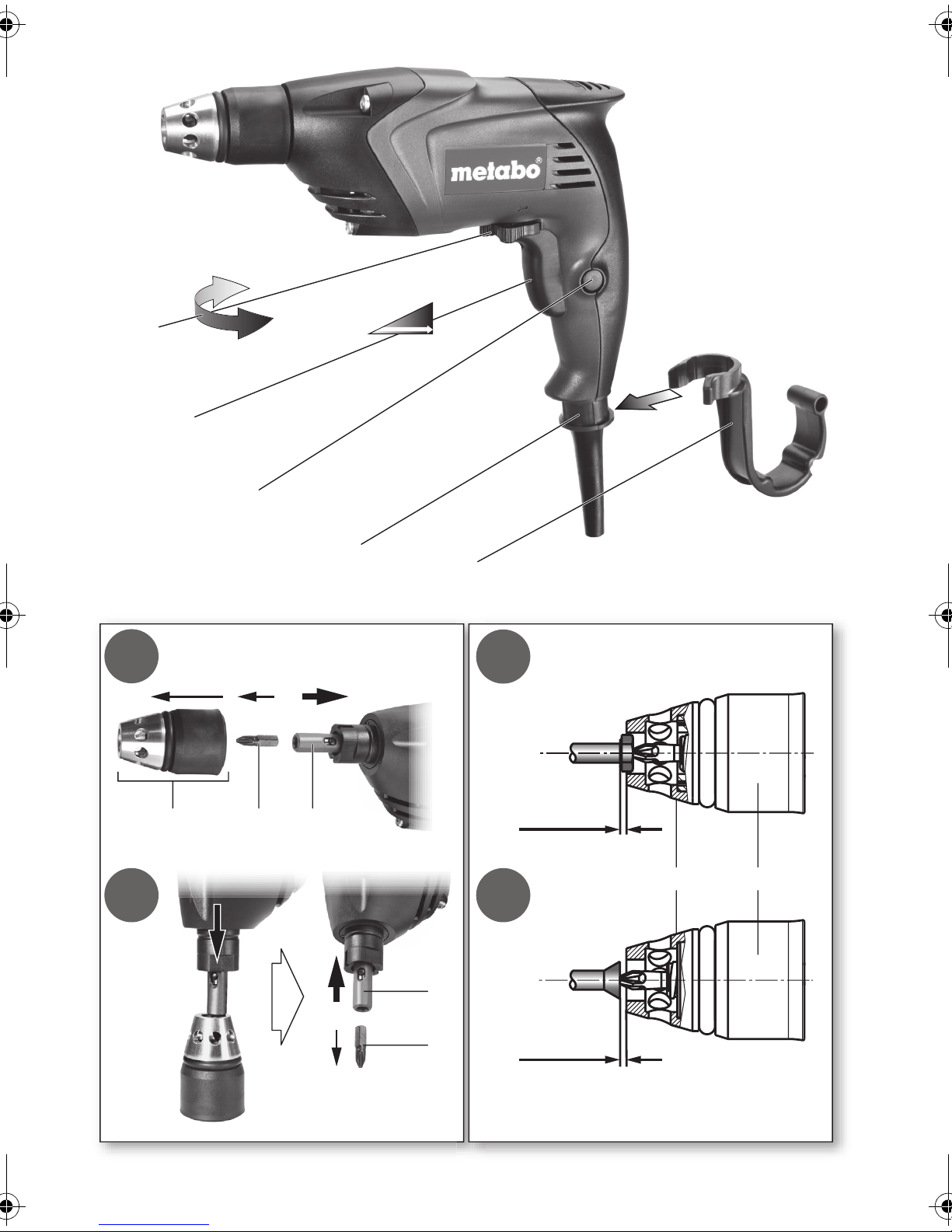
4 Functional Description
See page 3 (please unfold).
1 Rotation selector switch
2Trigger
3 Locking button (continuous activation)
4 Scaffold hook mounting
5Scaffold hook *
6Depth stop
6
Page 7
ENGLISH
ENG
7Tool *
8 Quick-release lock
9 Stop sleeve
* depending on equipment/not in scope of delivery
5 Special Product Features
• Compact, light machine in barrel-type design
for continuous use
• Ergonomically designed housing for effortless
work
• Patented bit changing system
• Two-piece depth stop
• Fine adjustment of insertion depth
• Low-noise claw clutch
• Removable scaffold hook with integrated bit
depot (depending on equipment)
•
SE 4000:
Ideally suited for applications in dry construction, e.g. installation of gypsum plasterboards.
•
SE 2800:
Universal screwdriver for wood screws, drilling
screws and dry wall screws up to a diameter of
6.0 mm.
•
Depth stop:
Work with and without depth stop possible.
Removal of the depth stop does not alter the set
screw insertion depth. After refitting, work can
continue at the same insertion depth.
a
6 Commissioning
Before plugging in, check to see that the
rated mains voltage and mains frequency,
as stated on the rating label, match your
power supply.
Scaffold hook (5) assembly:
hood mounting (4)
desired position.
and turn until it engages in the
Clip into
scaffold
7Use
7.1 Switching On and Off
7.2 Selection of direction of rotation
Do not activate the rotation selector
switch (1) unless the motor has
completely stopped.
Select direction of rotation:
R = Clockwise
L = Counter-clockwise
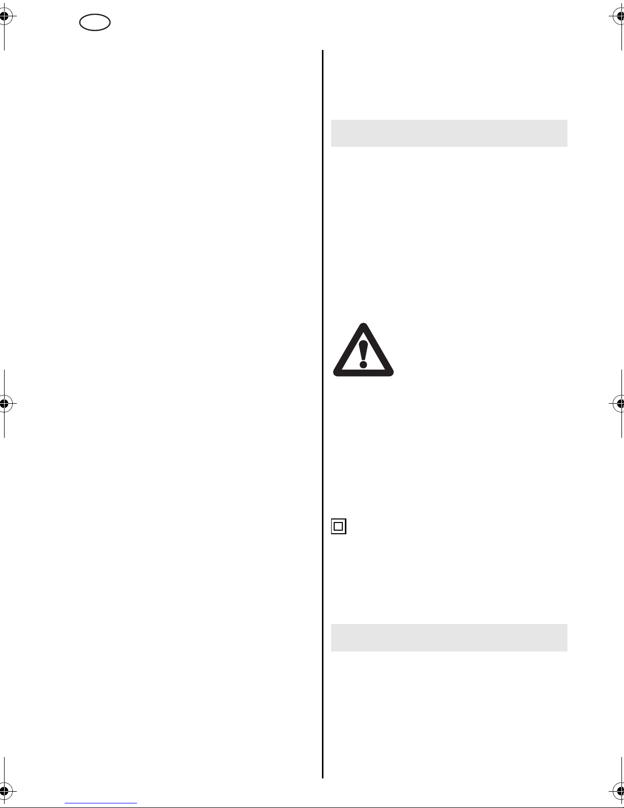
7.3 Tool change
Inserting tool:
Hold the quick-change lock (8) firmly in position
and insert tool.
Check that the quick-change lock (8) is in its front
position. Pull on the tool. The tool must be held
securely in position by the quick-change lock (8).
Removing the tool:
(See page 3, illustration 1a)
- Remove depth stop (6).
- Pull the quick-change lock (8) to the rear as far as
the stop (which unlocks the tool) and hold in this
rear position.
- Remove the tool (7).
If the quick-change lock (8) cannot be pushed to
the rear by hand, the depth can be used to do this.
Proceed as follows (see page 3, illustration 1b):
Option 1 :
- Insert the tool in a lateral bore of the depth stop
(6).
- Use the depth stop (6) to push the quick-change
lock (8) to the stop at the rear (this locks the tool).
- Remove the tool (7).
Option 2 :
- Place the depth stop (6) on a table, for example.
- Mount the machine with the quick-change lock
(8) on the upper edge of the depth stop (6).
- Position the quick-change lock (8) on the upper
edge so that the quick-change lock (8) is pushed
to the rear when the machine is pressed down.
- Press the machine down.
- Hold the quick-change lock (8) firmly in this in
position by hand.
- Remove the tool (7).
Fit the depth stop (6) again:
turn and engage in position when mounting.
To start the machine, press the trigger switch (2).
The speed can be changed at the trigger switch by
pressing.
For continuous operation the trigger switch can be
locked using the lock button (3). To stop the
machine, press the trigger switch again.
7.4 Working with depth stop
See page 3, illustration 2 a and 2 b.
To preset screw insertion depth, one of the screws
to be inserted is fitted on the tool. Set the depth
stop (6) by turning as follows:
a) Screws whose heads are to sit on the material
(socket-head screws, oval head screws, hex
7
Page 8
ENG
ENGLISH
screws): the surface area of the screw head is 2
mm outside the stop sleeve (9).
b) Flat head screws: The surface area of the screw
head is 2 mm outside the stop sleeve (9).
Insert a screw as a test. Correct the insertion depth
if necessary: When the depth stop (6) is inserted,
the insertion depth changes by 0.25 mm per notch.
If screw insertion has to be deeper: Insert stop
sleeve If the screw insertion is too deep: Unscrew
stop sleeve.
Removal of the depth stop (6) does not alter the set
screw insertion depth. After refitting, work can
continue at the same insertion depth.
When screwing in crosshead screws, press
the machine with the screwdriver bit firmly
against the screw until the screw is fully
inserted; otherwise the bit could slip out of the
cross recess and damage the material.
If the machine is not held exactly vertical in relation
to the tool, the depth stop counterbalances this (to
a certain extent).
7.5 Working without depth stop
Adapt the speed of the screwing process by carefully pressing in the trigger switch.
When the screwing process is complete, switch off
the machine by releasing the trigger switch (2).
If the long hole in the quick-change lock (8) is
contaminated, clean it and blow out with
compressed air. Pour some oil into the long hole if
necessary.
Remove the depth stop (6) regularly and clean it
f
11 Accessories
Use only genuine Metabo accessories.
If you need any accessories, check with your
dealer.
For dealers to select the correct accessory, they
need to know the exact model designation of your
power tool.
See page 4.
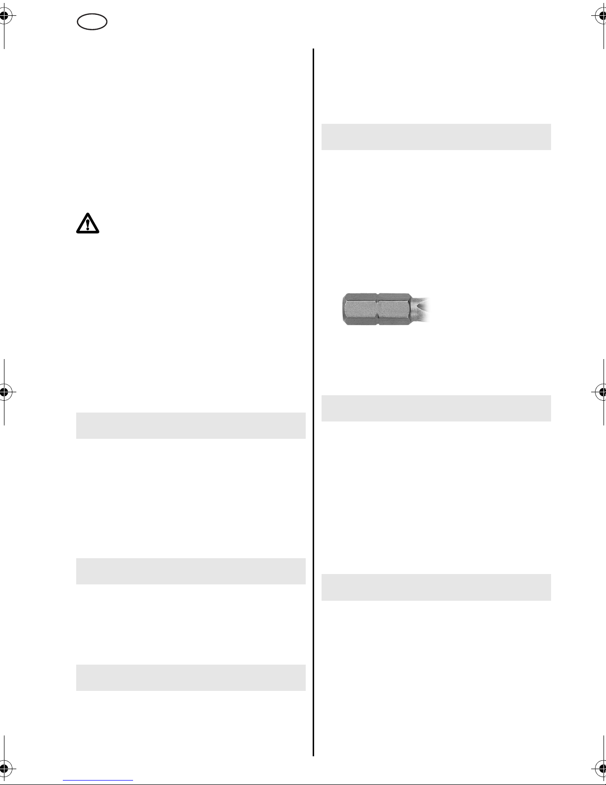
A Screwdriver bits (length: 25 mm)
Recommendation: only use screwdriving bits
with insertions like this:
B Scaffold hook with integrated bit depot
For complete range of accessories, see
www.metabo.com or the main catalogue.
8 Tips and Tricks
Press the machine firmly against the screw until
the screwing process is complete.
This is particularly important when inserting dry
wall screws (with coarse threads) in gypsum plasterboards because the large thread pitch of the
screws means that they are very quickly inserted.
If the stop sleeve (9) is stiff, it can be removed to
clean the thread.
.
9 Troubleshooting
If the screwdriver bit is too tightly fitted in the toolholder, pull the screwdriver bit out with pliers or
push the quick-change lock (8) to the rear with the
help of the depth stop. See the chapter on Tool
change
ENG
10 Maintenance
12 Repairs
Repairs to electrical tools must be carried out by
qualified electricians ONLY!
The connection cable must only be replaced by
Metabo or an authorised customer service workshop.
Any Metabo power tool in need of repair can be
sent to one of the addresses listed in the spare
parts list.
Please enclose a description of the fault with the
power tool.
13 Environmental Protection
Metabo's packaging can be 100% recycled.
Scrap power tools and accessories contain large
amounts of valuable resources and plastics that
can be recycled.
These instructions are printed on chlorine-free
bleached paper.
Disconnect the mains plug before starting any
maintenance work.
Motor cleaning: blow out the machine regularly
through the rear air slots with compressed air.
8
Page 9

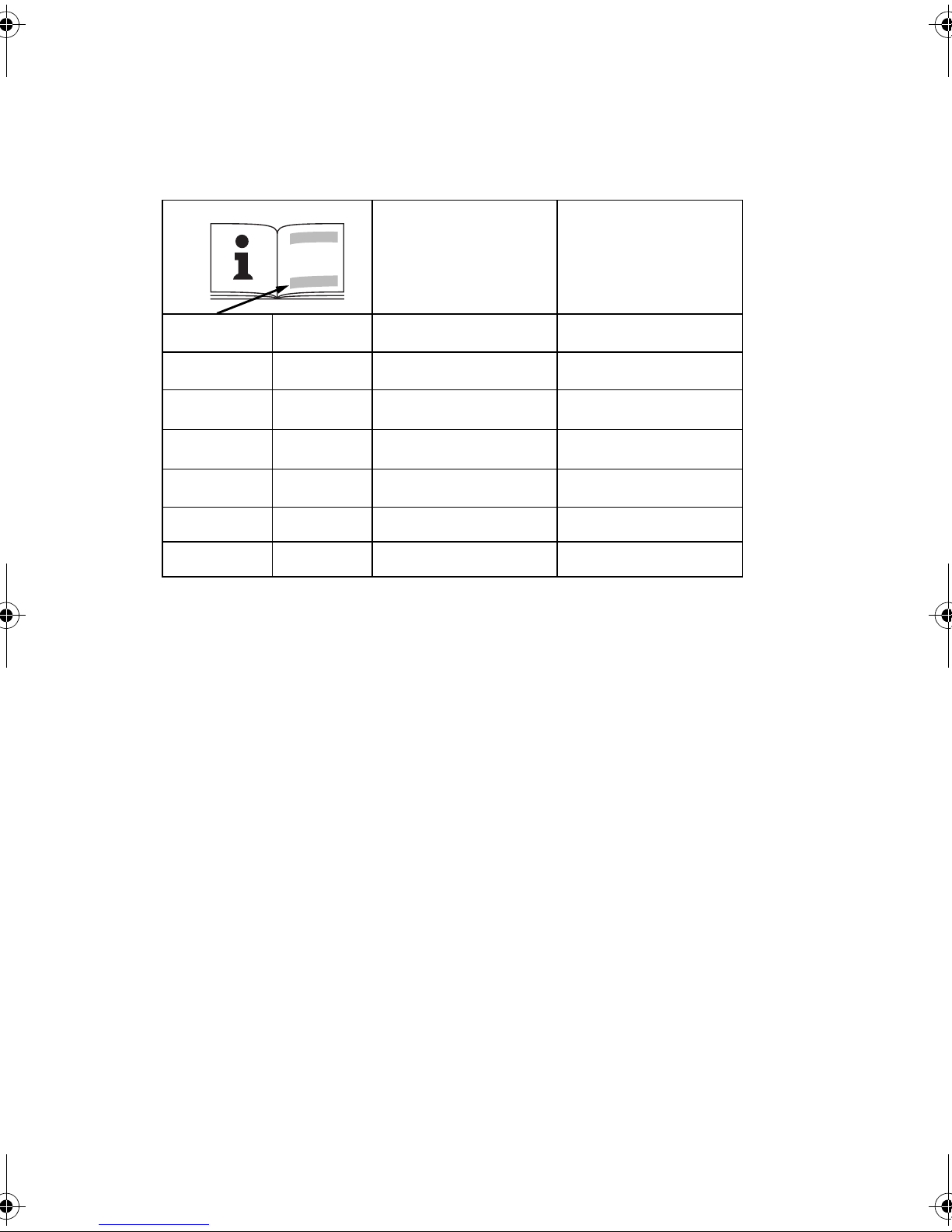
14 Technical Specifications
Explanatory notes on the specifications on page 2.
Changes due to technological progress reserved.
ENGLISH
ENG
P
1
= Nominal power input
P2 = Power output
n
n
T
0
1
max.
= No load speed
= On-load speed
= Max. tightening torque
H = Machine toolholder
m = Weight without mains cable
During operation the noise level can exceed
85 dB(A).
Wear ear protectors!
The technical specifications quoted are subject to
tolerances (in compliance with the relevant valid
standards).
9
Page 10

F
FRANÇAIS
Mode d'emploi
Cher client,
merci de la confiance que vous nous avez témoignée en achetant un outil électrique Metabo. Tous les
outils électriques Metabo sont testés avec soin et font l'objet de contrôles qualité très stricts effectués
par le Service Qualité Metabo. Mais c'est vous qui avez la plus grande influence sur la durée de vie de
votre outil électrique. Veuillez respecter les informations contenues dans ces instructions d'utilisation et
dans les documents ci-joints. En prenant grand soin de votre outil électrique Metabo, vous en
augmenterez la durée de vie et en garantirez le bon fonctionnement.
Sommaire
1 Utilisation conforme à la destination
2 Consignes générales de sécurité
3 Consignes de sécurité particulières
4Vue d'ensemble
5 Particularités du produit
6Mise en service
7 Utilisation
7.1 Marche/arrêt
7.2 Sélection du sens de rotation
7.3 Changement d'embout
7.4 Travaux avec la butée de profondeur
7.5 Travaux sans la butée de profondeur
8 Conseils et astuces
9 Dépannage
10 Maintenance
11 Accessoires
12 Réparations
13 Protection de l'environnement
14 Caractéristiques techniques
2 Consignes générales de
sécurité
AVERTISSEMENT !
instructions. Le non-respect des instructions
consignées ci-dessous peut être la cause de
chocs électriques, d'incendie et/ou de blessures
graves. Le terme „outil électrique“ utilisé dans tous
les avertissements répertoriés ci-après fait
référence à votre outil électrique alimenté sur
secteur (à fil) ou sur batterie (sans fil).
CONSERVEZ CES INSTRUCTIONS
1)
Sécurité de l'espace de travail
a)
Veillez au nettoyage et au bon éclairage de
l'espace de travail.
propices aux accidents.
b)
N'utilisez pas d'outils électriques dans des
atmosphères explosives, comme en présence
de liquides inflammables, de gaz ou de
poussière.
étincelles susceptibles d'enflammer les poussières
ou vapeurs.
c)
Éloignez les enfants et les tiers pendant le
fonctionnement d'un outil électrique.
pouvez perdre le contrôle en étant distrait.
Les outils électriques créent des
Lisez attentivement les
Les espaces encombrés sont
Vous
1 Utilisation conforme à la
destination
Cet outil convient pour visser et dévisser des vis
sur bois, panneaux de placoplâtre posés sur rails
métalliques ou ossature bois, plastiques et
matériaux assimilés.
L'outil n'est pas destiné au vissage et dévissage
de vis d'assemblage de métaux.
L'utilisateur sera entièrement responsable de tous
dommages résultant d'une utilisation non
conforme à la destination de la machine.
Il est impératif de respecter les consignes
générales de protection contre les accidents ainsi
que les consignes de sécurité ci-jointes.
10
2)
Sécurité électrique
a)
Les fiches d'alimentation des outils
électriques doivent correspondre à la prise de
courant. Ne modifiez jamais la fiche en aucune
manière. N'utilisez pas de fiches d'adaptation
avec les outils électriques à la masse.
modification des fiches et la conformité des prises
de courant permettront de réduire le risque de
choc électrique.
b)
Évitez le contact avec les surfaces mises à la
terre ou la masse comme les tuyaux, les
radiateurs, les cuisinières et les réfrigérateurs.
Le risque de choc électrique est accru en cas de
corps mis à la terre ou à la masse.
c)
N'exposez pas les outils électriques à la pluie
ni à l'humidité.
électrique accroît le risque de choc électrique.
d)
Ménagez le cordon d'alimentation. Ne
portez, tirez ni débranchez l'outil électrique par
le cordon. Éloignez le cordon d'alimentation de
toute source de chaleur, de surfaces
graisseuses, d'arêtes vives et de pièces
La pénétration d'eau dans un outil
La non
Page 11

FRANÇAIS
F
mobiles. Des cordons endommagés ou
enchevêtrés augmentent le risque de choc
électrique.
e)
Si vous utilisez un outil électrique à
l'extérieur, prévoyez une rallonge adaptée aux
conditions extérieures.
adapté aux conditions extérieures réduit le risque
de choc électrique.
3)
Sécurité personnelle
a)
Restez vigilant et attentif à ce que vous faites
et faites preuve de bon sens lorsque vous vous
servez d'un outil électrique. N'utilisez pas
d'outil électrique si vous êtes fatigué ou sous
l'influence de l'alcool, d'un médicament ou
d'une drogue.
le maniement d'outils électriques peut entraîner
des blessures graves.
b)
Utilisez des dispositifs de protection. Portez
toujours des lunettes de sécurité.
dans les bonnes conditions, de dispositifs de
protection comme les masques anti-poussière,
chaussures de sécurité antidérapantes ou
protections auditives réduit les blessures
corporelles.
c)
Évitez les démarrages intempestifs. Vérifiez
que la gâchette est déverrouillée avant le
branchement.
doigt sur la gâchette ou leur branchement avec la
gâchette verrouillée est propice aux accidents.
d)
Retirez toute clavette de calage ou clé de
réglage avant de mettre l'outil électrique en
marche.
en mouvement de l'outil électrique risque de
provoquer des blessures corporelles.
e)
N'adoptez pas une posture instable. Restez
bien ancré au sol et gardez l'équilibre à tout
instant.
électrique dans des situations inattendues.
f)
pas de vêtements amples ni de bijoux. Prenez
soin de garder vos cheveux, vêtements et gants
à l'écart des pièces en mouvement.
vêtements amples, les bijoux ou les cheveux longs
risquent d'être pris dans les pièces en mouvement.
g)
branchement de dépoussiéreurs ou de
collecteurs de déchets, vérifiez que ceux-ci
sont correctement branchés et utilisés.
L'utilisation de ces dispositifs peut réduire les
dangers associés à la poussière.
4)
a)
électrique correspondant à votre application.
L'utilisation du bon outil électrique permet
d'obtenir de meilleurs résultats avec une plus
grande sécurité et avec un rendement pour lequel
il a été conçu.
b)
ne fonctionne pas.
Portez des vêtements appropriés. Ne portez
En cas de dispositifs prévus pour le
Utilisation et entretien des outils électriques
Ne forcez pas l'outil électrique. Utilisez l'outil
N'utilisez pas l'outil électrique si la gâchette
Un moment d'inattention pendant
Le port d'outils électriques avec le
Une clé ou une clavette fixée à une pièce
Ceci permet un meilleur contrôle de l'outil
L'utilisation d'un cordon
L'utilisation,
Les
Tout outil électrique dont la
gâchette est défectueuse représente un danger et
doit faire l'objet d'une réparation.
c)
Débranchez la fiche de la source électrique
et/ou la batterie de l'outil électrique avant de
procéder à des réglages, changer
d'accessoires ou de ranger les outils
électriques.
réduisent le risque de démarrage intempestif des
outils électriques.
d)
Rangez les outils électriques hors de la
portée des enfants et ne laissez pas les
personnes non familiarisées avec un outil
électrique ou avec ces instructions, utiliser
l'outil concerné.
non formées, les outils électriques constituent un
danger.
e)
Assurez la maintenance des outils
électriques. Recherchez le défaut d'alignement
ou grippage des pièces en mouvement, la
rupture de pièces ou tout autre état susceptible
d'affecter la bonne marche des outils
électriques. En cas de dommage constaté,
faites réparer l'outil électrique avant de
l'utiliser.
maintenance défectueuse des outils électriques.
f)
Veillez à la propreté et l'affûtage des outils de
coupe.
arêtes tranchantes sont moins sujets au grippage
et plus faciles à contrôler.
g)
Utilisez l'outil électrique, les accessoires, les
outils rapportés, etc. conformément à ces
instructions et de la manière prévue pour ce
type particulier d'outil, en tenant compte des
conditions d'exécution et du travail à réaliser.
L'utilisation d'un outil électrique à des fins autres
que celles prévues peut constituer une situation
dangereuse.
5)
Entretien
a)
Faites effectuer l'entretien de votre outil
électrique par une personne qualifiée qui utilise
uniquement des pièces de rechange
identiques.
de l'outil électrique.
Ces mesures préventives de sécurité
Dans les mains de personnes
De nombreux accidents sont dus à une
Les outils de coupe bien entretenus et aux
Ceci assure le maintien de la sécurité
3 Consignes de sécurité
particulières
Tenez les outils électriques par les surfaces de
prise isolantes lorsque vous exécutez une
opération au cours de laquelle l'outil de coupe
risque d'être en contact avec un câble caché
ou avec son propre cordon.
câble nu met les pièces métalliques exposées
sous tension et soumet l'opérateur à un choc
électrique.
Portez une protection auditive.
bruit peut engendrer une perte de capacité
auditive.
Avant d'utiliser l'outil électrique, lisez attentivement et entièrement les instructions de sécurité ci-
Le contact avec un
L'exposition au
11
Page 12

F
FRANÇAIS
jointes (carnet rouge) ainsi que le mode d'emploi.
Conservez les documents ci-joints et veillez à les
remettre obligatoirement avec l'appareil à tout
utilisateur concerné.
Dans l'intérêt de votre propre
sécurité et afin de protéger votre
outil électrique, respectez les
passages de texte marqués de ce
symbole !
Débrancher le cordon d'alimentation de la prise de
courant avant toute opération de réglage ou de
maintenance.
Attention aux fils électriques, aux conduites de gaz
et d'eau !
Des couples de réaction importants sont susceptibles de se produire pendant l'opération. Il convient
donc de toujours maintenir l'outil avec fermeté, de
prendre une posture stable et de se concentrer sur
son travail.
Ne pas fermer les fentes d'aération.
SYMBOLES SUR L’OUTIL:
...........Construction de classe II
V...............volts
A...............ampères
Hz.............hertz
~...............courant alternatif
n
.............vitesse à vide
0
../min .......révolutions par minute
• Butée de profondeur en deux parties
• Réglage fin de la profondeur de vissage
• Embrayage à griffes silencieux
• Crochet pour échafaudage amovible avec
rangement pour embouts (suivant version)
•
SE 4000 :
L'outil idéal en installation intérieure, par ex.
pour la fixation de panneaux de placoplâtre.
•
SE 2800 :
La visseuse pour une utilisation universelle avec
des vis à bois, vis autoperçantes et vis pour
pose rapide, diamètres jusqu'à 6,0 mm.
•
Butée de profondeur :
Les travaux sont possibles avec et sans butée
de profondeur. Le fait d'enlever la butée de
profondeur ne modifie aucunement la profondeur de vissage choisie. On peut donc continuer
à travailler avec la même profondeur de vissage
après avoir remis la butée en place.
a
6 Mise en service
Avant la mise en service, comparez si
tension secteur et la fréquence secteur indiquées sur la plaque signalétique correspondent aux caractéristiques de votre réseau
de courant.
Mise en place du crochet pour échafaudage (5):
Clipser le crochet sur la
tourner jusqu'au blocage sur le cran voulu.
fixation du crochet (4)
puis
4Vue d'ensemble
Voir page 3 (à déplier).
1 Commutateur du sens de rotation
2 Gâchette
3 Bouton de marche continue
4 Fixation pour crochet d'échafaudage
5 Crochet pour échafaudage *
6 Butée de profondeur
7Embout *
8 Fermeture autoserrante
9 Douille de butée
* suivant version/non compris dans la fourniture
5 Particularités du produit
• Machine compacte et légère en conception
monobloc pour l'utilisation en continu
• Corps de forme ergonomique permettant de
travailler sans fatigue
• Système breveté pour le changement
d'embouts
7 Utilisation
7.1 Marche/arrêt
Pour mettre l'outil en route, appuyer sur la
gâchette (2).
La vitesse peut être modifiée en pressant la
gâchette.
Pour un fonctionnement en continu, il est possible
de bloquer la gâchette à l'aide du bouton de
blocage (3). Pour arrêter la machine, appuyer à
nouveau sur la gâchette.
7.2 Sélection du sens de rotation
S'assurer que le moteur est à l'arrêt
avant d'actionner le commutateur du
sens de rotation (1).
Sélectionner le sens de rotation:
R = Rotation à droite
L = Rotation à gauche
12
Page 13

FRANÇAIS
F
7.3 Changement d'embout
Mise en place de l'embout :
Maintenir la fermeture autoserrante (8) et mettre
l'embout en place.
Vérifier que la fermeture autoserrante (8) se trouve
dans sa position avant. Tirer l'embout. L'embout
doit maintenir la fermeture autoserrante (8) de
manière sûre.
Dépose de l'embout :
(voir page 3, figure 1a)
- Retirer la butée de profondeur (6).
- Tirer la fermeture autoserrante (8) vers l'arrière
jusqu'à la butée (ce qui verrouille l'embout) et la
maintenir dans cette position arrière.
- Déposer l'embout (7).
Si la fermeture autoserrante (8) résiste lorsque l'on
la tire vers l'arrière à la main, on peut s'aider en
poussant sur la butée de profondeur. Voici la
procédure à suivre (voir page 3, figure 1b) :
Possibilité 1 :
- Placer l'embout dans l'alésage latéral de la butée
de profondeur (6).
- Pousser la fermeture autoserrante (8) avec la
butée de profondeur (6) jusqu'à la butée vers
l'arrière ce qui permet de déverrouiller l'embout.
- Déposer l'embout (7).
Possibilité 2 :
- Poser la butée de profondeur (6), par ex. sur une
table.
- Poser la machine, en appliquant la fermeture
autoserrante (8) sur le bord supérieur de la butée
de profondeur (6).
- Positionner la fermeture autoserrante (8) sur le
bord supérieur de manière qu'en poussant la
machine vers le bas, la fermeture autoserrante (8)
sera poussée en arrière.
- Pousser la machine vers le bas.
- Maintenir la fermeture autoserrante (8) à la main
dans cette position arrière.
- Déposer l'embout (7).
Remettre en place la butée de profondeur (6) :
Tourner en la positionnant et la bloquer sur son
cran.
7.4 Travaux avec la butée de profondeur
Voir page 3, figures 2 a et 2 b.
Pour le préréglage de la profondeur de vissage,
placer l'une des vis à insérer sur l'embout. Régler
la butée de profondeur (6) par rotation comme
suit :
a) Pour les vis dont la tête devra se poser sur le
support (vis à tête cylindrique, vis à tête goutte-desuif, vis à tête six pans) :
La face d'appui de la tête de vis dépasse la douille
de butée (9) de 2 mm.
b) Vis à tête fraisée :
La face de la tête de vis dépasse la douille de
butée (9) de 2 mm.
Visser une vis pour faire un essai. Si nécessaire,
corriger la profondeur de vissage comme suit :
Lors de la rotation de la butée de profondeur (6), la
profondeur de vissage est modifiée de 0,25 mm
par cran. Pour un vissage plus profond de la vis,
serrer davantage la douille de butée. Si la vis est
déjà vissée trop profond : desserrer la douille de
butée.
Le fait d'enlever la butée de profondeur (6) ne
modifie aucunement la profondeur de vissage
choisie. On peut donc continuer à travailler avec la
même profondeur de vissage après avoir remis la
butée en place.
Lors du vissage de vis à empreinte cruciforme, fermement appliquer l'embout de la
visseuse sur la vis jusqu'à la fin de l'opération. En effet, avec une force insuffisante, l'embout
risquerait de sortir de l'empreinte cruciforme et
d'endommager le support.
Si la machine n'est pas maintenue exactement à la
verticale de la pièce, la butée de profondeur
compense ce défaut de verticalité jusqu'à un
certain degré.
7.5 Travaux sans la butée de profondeur
Adapter la vitesse de vissage à l'opération en
cours en modulant la pression exercée sur la
gâchette.
Après avoir terminé le vissage, la machine est
arrêtée en relâchant la gâchette (2).
8 Conseils et astuces
La machine doit être fermement appliquée sur la
vis jusqu'à la fin de l'opération de vissage.
Ce point est particulièrement important pour le
vissage de vis pour pose rapide (munies d'un
filetage à pas gros) sur des panneaux de placoplâtre. En effet, le pas important de ces vis fait que
leur vissage est très rapide.
Lorsque la douille de butée (9) n'est pas suffisamment mobile, on peut la dévisser afin d'en nettoyer
le filetage.
.
9 Dépannage
Lorsqu'un embout de vissage est serré trop fermement dans le porte-embouts : sortir l'embout de
vissage à l'aide d'une pince ou pousser la fermeture autoserrante (8) en arrière à l'aide de la butée
13
Page 14

F
de profondeur. Voir chapitre Changement
d'embout.
F
FRANÇAIS
13 Protection de
l'environnement
10 Maintenance
Avant toute intervention de maintenance, retirer la
prise du cordon du secteur !
Nettoyage du moteur : nettoyer la machine régulièrement en soufflant de l'air comprimé à travers
les fentes d'aération à l'arrière.
S'il est encrassé, le trou oblong sur la fermeture
autoserrante (8) devra être nettoyé et soufflé à l'air
comprimé. Si nécessaire introduire un peu d'huile
dans le trou oblong.
Régulièrement déposer et nettoyer la butée de
profondeur (6).
f
11 Accessoires
Utilisez uniquement du matériel Metabo.
S'il vous faut des accessoires, veuillez vous
adresser à votre revendeur.
Pour pouvoir sélectionner les accessoires appro-
priés, veuillez indiquer le type exact de votre outil
électrique au distributeur.
Voir page 4.
A Embouts de visseuse (longueur : 25 mm)
Recommandation : n'utiliser que des embouts
de vissage munis d'extrémités de montage de
ce type :
B Crochet pour échafaudage avec rangement
d'embouts incorporé
Les emballages Metabo sont recyclables à 100 %.
Les outils et accessoires électriques qui ne sont
plus utilisés contiennent de grandes quantités de
matières premières et de matières plastiques de
grande qualité pouvant être également recyclées.
Ce mode d'emploi est imprimé sur du papier
blanchi sans chlore.
14 Caractéristiques
techniques
Commentaires sur les indications de la page 2.
Sous réserve de modifications allant dans le sens
du progrès technique.
P
1
P
2
n
0
n
1
T
max.
H = Porte-embouts de la machine
m = Poids sans cordon d'alimentation
Pendant le fonctionnement, il se peut que le niveau
sonore dépasse les 85 db(A).
Les caractéristiques indiquées sont soumises à
tolérance (selon les normes en vigueur correspondantes).
= Puissance absorbée
= Puissance débitée
= Vitesse à vide
= Vitesse en charge
= Couple de serrage maxi
Porter un casque antibruit !
Voir programme complet des accessoires sur
www.metabo.com ou dans le catalogue principal.
12 Réparations
Les travaux de réparation sur les outils électriques
ne peuvent être effectués que par un spécialiste !
Seul Metabo ou un atelier de service autorisé est
habilité à effectuer le remplacement du câble de
raccordement.
Les outils Metabo qui sont à réparer peuvent être
expédiés à l'une des adresses indiquées sur la
liste des pièces de rechange.
Prière de joindre à l'outil expédié une description
du défaut constaté.
14
Page 15

ESPAÑOL
ES
Instrucciones de manejo
Estimado cliente,
le agradecemos la confianza depositada en nosotros al comprar una herramienta eléctrica Metabo. Cada
herramienta Metabo ha sido probada cuidadosamente y ha superado los estrictos controles de calidad
de Metabo. Sin embargo, la vida útil de una herramienta eléctrica depende en gran medida de usted. Le
rogamos que tenga en cuenta la información contenida en estas instrucciones y en los documentos
adjuntos. Una mejor conservación de su herramienta eléctrica de Metabo, repercute en un servicio eficaz
durante más tiempo.
Contenido
1 Aplicación de acuerdo a la finalidad
2 Instrucciones generales de seguridad
3 Instrucciones especiales de seguridad
4 Descripción general
5 Características especiales del producto
6 Puesta en marcha
7Manejo
7.1 Conexión/desconexión
7.2 Selección del sentido de giro
7.3 Cambio de herramienta
7.4 Trabajar con tope de profundidad
7.5 Trabajar sin tope de profundidad
8 Consejos y trucos
9 Localización de averías
10 Mantenimiento
11 Accesorios
12 Reparación
13 Protección ecológica
14 Especificaciones técnicas
1 Aplicación de acuerdo a la
finalidad
La herramienta se ha diseñado para apretar y
aflojar tornillos en madera, en placas de cartón de
yeso, en barras de perfil de metal o construcciones de madera, en plásticos y materiales similares.
La herramienta no es apta para apretar y aflojar
tornillos de máquinas en materiales de metal.
Los posibles daños derivados de un uso inadecuado son responsabilidad exclusiva del usuario.
Deben observarse los reglamentos para la prevención de accidentes y las instrucciones de seguridad incluidas.
2 Instrucciones generales de
seguridad
ATENCIÓN
de manejo. Si no se siguen todas las instrucciones
que se describen a continuación se corre el riesgo
de sufrir una descarga eléctrica, lesiones graves o
causar un incendio. El término "herramienta
eléctrica" que se utiliza en las siguientes
advertencias se refiere tanto a las herramientas
eléctricas de alimentación por red (con cable)
como a las herramientas eléctricas de
alimentación por batería (sin cable).
GUARDE ESTAS INSTRUCCIONES
1)
Seguridad en el lugar de trabajo
a)
Mantenga el lugar de trabajo limpio y bien
iluminado.
pueden dar lugar a accidentes.
b)
No trabaje con herramientas eléctricas en
lugares con peligro de explosión, como p. ej.
lugares donde se almacenan líquidos
inflamables, gases o polvo.
eléctricas producen chispas que pueden encender
el polvo o el humo.
c)
Mantenga alejados a los niños y a otras
personas mientras trabaje con la herramienta
eléctrica.
pérdida del control.
2)
Seguridad eléctrica
a)
Los enchufes de la herramienta eléctrica
tienen que ser compatibles con la toma de
corriente En ningún caso se debe modificar el
enchufe. No utilice ningún adaptador de
enchufe con herramientas eléctricas con
conexión a masa (toma de tierra).
que no han sido manipulados y las tomas de
corriente compatibles reducen el riesgo de
descarga eléctrica.
b)
Evite el contacto corporal con superficies
con toma a masa o tierra, como tubos,
radiadores, cocinas y refrigeradores.
mayor riesgo de descarga eléctrica si su cuerpo se
halla en contacto con el suelo.
c)
No exponga las herramientas eléctricas a la
lluvia o la humedad.
herramienta eléctrica, aumenta el riesgo de
descarga eléctrica.
Lea completamente las instrucciones
Los lugares desordenados y oscuros
Las herramientas
Las distracciones pueden provocar la
Los enchufes
Existe un
Si entra agua en una
15
Page 16

ES
d)
No fuerce el cable. Nunca utilice el cable
para transportar la herramienta, tirar de ella o
desenchufarla. Mantenga el cable alejado de
fuentes de calor, aceite, bordes cortantes y
piezas móviles.
hacen que aumente el riesgo de descarga
eléctrica.
e)
Cuando trabaje con herramientas eléctricas
al aire libre, utilice un alargo apto para uso
exterior.
exteriores reduce el riesgo de descarga eléctrica.
3)
Seguridad personal
a)
Preste atención a lo que está haciendo y use
el sentido común al trabajar con una
herramienta eléctrica. No utilice una
herramienta si está cansado o se encuentra
bajo la influencia de las drogas, el alcohol o
medicación.
herramientas eléctricas puede causar un grave
accidente.
b)
Utilice accesorios de seguridad. Utilice
siempre protección ocular.
seguridad, como la mascarilla antipolvo, el calzado
especial antideslizante, el casco o los protectores
para los oídos, reducen el riesgo de lesiones si se
utilizan en las condiciones apropiadas .
c)
Evite el accionamiento accidental de la
herramienta. Compruebe que el interruptor
está en la posición off antes de enchufarla.
evitar accidentes, evite transportar las
herramientas eléctricas con el dedo situado en el
interruptor o enchufar las herramientas eléctricas
con el interruptor en la posición on.
d)
Retire cualquier llave de ajuste o llave de
tuercas antes de encender la herramienta
eléctrica.
fijada en alguna pieza giratoria de la herramienta
eléctrica, ya que podría causarle lesiones.
e)
No se extralimite. Mantenga la estabilidad y
el equilibrio en todo momento.
mejor control de la herramienta eléctrica en
situaciones inesperadas.
f)
Vístase adecuadamente. Evite llevar puestas
ropa ancha o joyas. Mantenga el pelo, la ropa y
los guantes alejados de las piezas móviles.
ropa ancha, las joyas o el pelo largo se pueden
enganchar en las piezas móviles.
g)
Si se suministran dispositivos para la
conexión de herramientas de aspiración y
captación de polvo, asegúrese de que están
bien conectados y se usan correctamente.
utilización de estos dispositivos puede reducir los
riesgos provocados por el polvo.
ESPAÑOL
Los cables dañados o enredados
La utilización de un cable apto para
Un pequeño descuido al trabajar con
Los accesorios de
Evite dejar cualquiera de estas llaves
Ello permite un
Para
La
La
b)
No utilice la herramienta eléctrica si el
interruptor no funciona correctamente.
Cualquier herramienta eléctrica que no se pueda
controlar con el interruptor es peligrosa y debe
repararse.
c)
Desconecte el enchufe de la fuente de
alimentación y extraiga la batería de la
herramienta antes de hacer cualquier
reparación, cambiar accesorios o almacenar
las herramientas eléctricas.
seguridad preventivas reducen el riesgo de que la
herramienta eléctrica se encienda
accidentalmente.
d)
Mantenga las herramientas eléctricas fuera
del alcance de los niños y no permita que la
utilicen personas ajenas a la herramienta
eléctrica o a estas instrucciones.
herramientas eléctricas son peligrosas en manos
de usuarios inexpertos.
e)
Mantenimiento de las herramientas
eléctricas. Compruebe la alineación y los
puntos de unión de las piezas móviles, la rotura
de piezas o cualquier otro aspecto que pueda
afectar al funcionamiento de las herramientas
eléctricas. Si se avería, repare la herramienta
eléctrica antes de usarla.
deben al mantenimiento inadecuado de las
herramientas eléctricas.
f)
Mantenga las herramientas cortadoras
limpias y afiladas.
las herramientas cortadoras y el afilado periódico
de los cantos de corte reduce el riesgo de
agarrotamiento de las herramientas y facilita el
control de las mismas.
g)
Utilice la herramienta eléctrica, los
accesorios, las puntas y láminas de atornillar,
etc. siguiendo estas instrucciones de la
manera prevista para cada tipo de herramienta
eléctrica, teniendo en cuenta las condiciones
de trabajo y el trabajo que hay que llevar a
cabo.
Un uso indebido de la herramienta eléctrica
podría originar situaciones peligrosas.
5)
Servicios
a)
El servicio y reparación de la herramienta
eléctrica debe llevarlo a cabo una persona
cualificada y utilizando sólo piezas de
recambio originales.
que se mantenga la seguridad de la herramienta
eléctrica.
El adecuado mantenimiento de
De este modo se asegura
Estas medidas de
Muchos accidentes se
Las
3 Instrucciones especiales
de seguridad
4)
Cuidado y uso de las herramientas eléctricas
a)
No fuerce la herramienta eléctrica. Utilice la
herramienta eléctrica apropiada para cada
aplicación.
trabajo mejor y de forma más segura a la velocidad
para la cual fue diseñada.
La herramienta apropiada hará el
16
Sujete las herramientas eléctricas por las
superficies de agarre con aislamiento cuando
realice un trabajo en el que la herramienta
cortadora pueda entrar en contacto con
cableado oculto o con su propio cable.
contacto con un cable "cargado" hará que las
piezas de metal expuestas de la herramienta se
El
Page 17

"carguen" y le transmitan una descarga eléctrica al
trabajador.
Lleve orejeras.
causar pérdida de audición.
Antes de utilizar esta herramienta, lea y entienda
completamente las instrucciones y la información
de seguridad (folleto rojo) incluidos. Guarde todos
los documentos para referencia en el futuro, y
solamente entregue su herramienta junto con
estos documentos.
Desenchufe el equipo antes de llevar a cabo cualquier ajuste o mantenimiento.
Tenga cuidado con las tuberías de gas y agua y los
cables eléctricos.
Al trabajar pueden aparecer momentos de retrogiro elevados. Sujete la máquina con fuerza,
adopte una postura segura y trabaje concentrado.
No tapar la ranura de ventilación.
SÍMBOLOS SOBRE LA HERRAMIENTA:
.................. Classe II de construcción
V......................voltios
A......................amperios
Hz....................hertzios
~
.....................corriente alterna
n0....................velocidad sin carga
../min ..............revoluciones por minuto
La exposición a ruidos puede
Para su propia protección y la de
su herramienta eléctrica, observe
las partes marcadas con este
símbolo.
ESPAÑOL
ES
5 Características especiales
del producto
• Máquina compacta, ligera y de construcción
tubular para una aplicación continua
• Carcasa con diseño ergonómico para trabajar
sin esfuerzo.
• Sistema patentado de cambio de puntas de
destornillador
• Tope de profundidad de dos piezas
• Ajuste preciso de la profundidad de atornillado
• Acoplamiento de garra silencioso
• Gancho de soporte desmontable con compartimiento de puntas de destornillador integrado
(según la versión)
•
SE 4000:
Es apropiada para su aplicación en construcciones en seco como p.ej. el montaje de placas
de cartón de yeso.
•
SE 2800:
Destornillador multiuso para tornillos para
madera, tornillos perforadores y tornillos de
sujeción rápida de hasta 6 mm de diámetro.
•
Tope de profundidad:
posibilidad de trabajar con o sin tope de
profundidad. Si se retira el tope de profundidad,
la profundidad de atornillado ajustada no varía.
Tras la colocación se puede seguir trabajando
con la misma profundidad de atornillado.
a
6 Puesta en marcha
4 Descripción general
Véase la página 3 (desplegarla).
1 Conmutador de giro
2Interruptor
3Botón de retención
(funcionamiento continuado)
4 Sujeción de gancho de soporte
5 Gancho de soporte *
6 Tope de profundidad
7 Herramientas *
8 Cierre de cambio rápido
9 Manguito de tope
* según la versión/no incluido en el volumen de
suministro
Antes de enchufar la herramienta,
compruebe que la tensión y la frecuencia
de red que se indican en la placa de identificación se corresponden con las características de la red eléctrica.
Montaje del gancho de soporte (5) :
sujeción de gancho de soporte (4)
que encaje en la posición deseada.
fíjelo
a la
y gírelo hasta
7Manejo
7.1 Conexión y desconexión
Pulse el interruptor (2) de la herramienta para
ponerla en marcha.
El número de revoluciones puede modificarse
presionando el interruptor.
Para un funcionamiento continuado puede
bloquearse el interruptor con el botón de retención
(3). Para parar la herramienta, pulse de nuevo el
interruptor.
17
Page 18

ES
ESPAÑOL
7.2 Selección del sentido de giro
Pulse el conmutador de giro (1) sola-
mente durante el estado de parada del
motor.
Selección del sentido de giro
R = giro a la derecha
L = giro a la izquierda
7.3 Cambio de herramienta
Insertar la herramienta:
Sujete el cierre de cambio rápido (8) e inserte la
herramienta.
Compruebe que el cierre de cambio rápido (8) se
halle en la posición delantera. Tire de la herramienta. La herramienta debe quedar bien sujeta
por el cierre de cambio rápido (8).
Extraer la herramienta:
(Véase la página 3, figura 1a)
- Cómo extraer el tope de profundidad (6).
- Tirar hacia atrás del cierre de cambio rápido (8)
hasta el tope (la herramienta se desbloquea) y
mantener en esta posición.
- Cómo retirar la herramienta (7).
Si el cierre de cambio rápido (8) no se puede
empujar manualmente hacia atrás, es posible
empujarlo hacia atrás con ayuda del tope de
profundidad. Procedimiento (véase la página 3,
imagen 1b):
Posibilidad 1 :
- Introducir la herramienta en un orificio lateral del
tope de profundidad (6).
- Con el tope de profundidad (6), empujar el cierre
de cambio rápido (8) hacia atrás hasta el tope (la
herramienta se desbloquea).
- Cómo retirar la herramienta (7).
Posibilidad 2 :
- Colocar el tope de profundidad, (6) p.ej. encima
de una mesa.
- Colocar la herramienta con el cierre de cambio
rápido (8) en el borde superior del tope de
profundidad (6).
- Colocar el cierre de cambio rápido (8) en el borde
superior de manera que cuando la máquina se
presione hacia abajo, el cierre de cambio rápido
(8) se desplace hacia atrás.
- Presionar hacia abajo la herramienta.
- Sujetar el cierre de cambio rápido (8) con la mano
en esta posición (hacia atrás).
- Cómo retirar la herramienta (7).
Volver a montar el tope de profundidad (6) :
Al colocarlo girarlo y encajarlo.
7.4 Trabajos con el tope de profundidad
Véase la página 3, imagen 2 a y 2 b.
Para preajustar la profundidad de atornillado debe
colocarse en la herramienta uno de los tornillos
que se van a apretar. Ajuste el tope de
profundidad (6) girándolo como se explica a continuación:
a) Tornillos que deban introducirse hasta que su
cabeza esté asentada sobre el material (tornillos
cilíndricos, tornillos de cabeza alomada, tornillos
de cabeza hexagonal):
La superficie de apoyo de la cabeza del tornillo se
encuentra a una distancia de 2 mm fuera del
manguito de tope. (9)
b) Tornillos avellanados:
La superficie de la cabeza de tornillo se encuentra
a una distancia de 2 mm fuera del manguito de
tope. (9)
Realice un atornillado de prueba. Si fuera necesario, corrija la profundidad de atornillado:
Al girar el tope de profundidad (6), la profundidad
de atornillado varía en 0,25 mm por trama. Para
atornillar a mayor profundidad, apriete el manguito
de tope. Para atornillar a menor profundidad, afloje
el manguito de tope.
Si se retira el tope de profundidad (6), la
profundidad de atornillado ajustada no varía. Tras
la colocación se puede seguir trabajando con la
misma profundidad de atornillado.
Al atornillar tornillos de estrella, presionar
con fuerza la herramienta con la lámina de
destornillador hasta finalizar el proceso de
atornillado, ya que en caso contrario la punta del
destornillador podría salirse de la ranura en cruz y
dañar el material.
Si la herramienta no se sujeta perpendicularmente
a la pieza de trabajo, el tope de profundidad lo
regula (hasta cierto punto).
7.5 Trabajar sin tope de profundidad
Ajustar el número de revoluciones al proceso de
atornillado apretando el interruptor.
Al finalizar el proceso de atornillado, apagar la
máquina desconectando el interruptor. (2) .
8 Consejos y trucos
Presionar la herramienta con fuerza contra el
tornillo hasta finalizar el proceso de atornillado.
Esto es importante especialmente al atornillar
tornillos de sujeción rápida (con rosca gruesa) en
placas de cartón de yeso, ya que estos tornillos se
atornillan muy rápido gracias a su paso de rosca
grande.
18
Page 19

ESPAÑOL
ES
Si el manguito de tope (9) se mueve con dificultad,
puede desatornillarse para limpiar la rosca.
.
9 Localización de averías
Si la lámina de destornillador en el portaherramientas de la máquina está muy apretada: extraer
la lámina de destornillador con unas tenazas o
empujar hacia atrás el cierre de cambio rápido (8)
con ayuda del tope de profundidad. Véase el
capítulo cambio de herramienta.
ES
10 Mantenimiento
Antes de llevar a cabo cualquier trabajo de
mantenimiento recuerde extraer el enchufe de la
toma de corriente.
Limpieza del motor: limpie periódicamente la
herramienta con aire comprimido por las ranuras
de ventilación traseras.
En caso de suciedad, limpiar con aire a presión la
ranura en el cierre de cambio rápido (8). En caso
necesario, aplicar un poco de aceite en la ranura.
Retirar y limpiar el tope de profundidad (6) con
regularidad
f
11 Accesorios
Use solamente accesorios originales Metabo.
Si necesita accesorios, consulte a su proveedor.
Para que el proveedor pueda seleccionar el acce-
sorio correcto, necesita saber la designación
exacta del modelo de su herramienta.
Véase la página 4.
A Láminas de destornillador (longitud: 25 mm)
Recomendación: utilizar sólo inserciones con
estos gorrones empotrables:
B Ganchos de soporte con compartimiento
integrado de puntas de destornillador
La sustitución del cable de conexión sólo puede
ser realizada por Metabo o un taller autorizado.
Cualquier herramienta Metabo, que requiera reparación, se puede enviar a una de las direcciones
indicadas en la lista de piezas de repuesto.
Sírvase incluir a la herramienta eléctrica enviada
para su reparación una descripción de la anomalía
determinada.
13 Protección ecológica
Los envases Metabo son 100% reciclables.
Las herramientas eléctricas y sus accesorios fuera
de uso contienen grandes cantidades de materia
prima y plásticos que también pueden ser reciclados.
Estas instrucciones están impresas en papel blanqueado sin cloro.
14 Especificaciones técnicas
Notas explicativas sobre la información de la
página 2.
Nos reservamos el derecho a efectuar modificaciones conforme al avance técnico.
P
1
P
2
n
0
n
1
T
máx.
H = Portaherramientas de la máquina
m = Peso sin cable a la red
Al trabajar, el nivel de ruido puede superar los
85 dB(A).
Las especificaciones técnicas aquí indicadas se
entienden dentro de determinadas tolerancias
(conformes a las normas que rigen actualmente).
= Potencia de entrada nominal
= Potencia suministrada
= Número de revoluciones en marcha
en vacío
= Revoluciones bajo carga
= Par de apriete máx.
¡Utilice cascos protectores para los
oídos!
Programa completo de accesorios disponible en
www.metabo.com o en el catálogo principal.
12 Reparación
Las reparaciones de herramientas eléctricas
SOLAMENTE deben ser efectuadas por técnicos
electricistas especializados!
19
Page 20

PT
PORTUGUÊS
Instruções de serviço
Caro Cliente,
agradecemos-lhe a confiança que deposita em nós ao comprar-nos esta ferramenta eléctrica Metabo.
Cada ferramenta Metabo é cuidadosamente testada e sujeita a controlos de qualidade exaustivos antes
de ser entregue. No entanto a vida útil de um equipamento deste tipo depende em grande parte do uso
e dos cuidados que lhe dão. Cumpra pois todas as indicações incluídas neste manual. Quanto mais
cuidadosamente tratar a sua ferramenta Metabo, maior será a longevidade que poderá esperar dela.
Índice
1 Utilização autorizada
2 Recomendações gerais de segurança
3 Notas de segurança especiais
4Vista geral
5 Características especiais do produto
6 Colocação em operação
7 Utilização
7.1 Ligar/desligar
7.2 Seleccionar o sentido de rotação
7.3 Troca de ferramentas
7.4 Trabalhar com limitador de
profundidade
7.5 Trabalhar sem limitador de
profundidade
8Conselhos úteis
9 Detecção de avarias
10 Manutenção
11 Acessórios
12 Reparações
13 Protecção ao meio-ambiente
14 Dados técnicos
1 Utilização autorizada
A ferramenta é adequada para aparafusar e desaparafusar parafusos em madeiras, em placas de
gesso prensado com cartão sobre barras de perfil
de metal, em plásticos e materiais similares.
A ferramenta não é adequada para aparafusar e
desaparafusar parafusos de maquinarias em
materiais de metal.
O utilizador é inteiramente responsável por qualquer dano que seja fruto de um uso indevido.
Deve sempre cumprir-se toda a regulamentação
aplicável à prevenção de acidentes, assim como a
informação sobre segurança que aqui se incluí.
2 Recomendações gerais de
segurança
AVISO!
cumprimento das instruções seguintes pode
resultar em choque eléctrico, incêndio e/ou
acidentes graves. O termo „ferramenta eléctrica“
em todos os avisos seguintes refere-se às
ferramentas eléctricas de ligação à rede eléctrica
(com fio) ou às ferramentas eléctricas alimentadas
por bateria (sem fio).
GUARDE ESTAS INSTRUÇÕES
1)
a)
iluminada.
um convite aos acidentes.
b)
atmosferas explosivas, tal como na presença
de líquidos, gases ou pó inflamáveis.
ferramentas eléctricas geram faíscas que podem
inflamar o pó ou fumos.
c)
afastados enquanto está a utilizar uma
ferramenta eléctrica.
com que perca o controlo.
2)
a)
ser adequadas às tomadas. Nunca altere a
ficha seja de que forma for. Não use fichas com
adaptador em ferramentas eléctricas ligadas à
terra (à massa).
correspondentes reduzem o risco de choque
eléctrico.
b)
com ligação à terra e à massa, tal como tubos,
radiadores e refrigeradores.
risco de choque eléctrico se o seu corpo ficar
ligado à terra ou à massa .
c)
chuva ou condições húmidas.
na ferramenta eléctrica aumenta o risco de choque
eléctrico.
d)
eléctrico. Nunca use o cabo eléctrico para
transportar, puxar ou desligar a ferramenta
eléctrica. Mantenha o cabo afastado do calor,
óleo, esquinas afiadas ou partes móveis.
Leia todas as instruções. O não
Segurança na área de trabalho
Mantenha a área de trabalho limpa e bem
As áreas desarrumadas e escuras são
Não utilize as ferramentas eléctricas em
As
Mantenha as crianças e os observadores
As distracções podem fazer
Segurança eléctrica
As fichas das ferramentas eléctricas têm de
Fichas não alteradas e tomadas
Evite o contacto do corpo com superfícies
Existe um maior
Não exponha as ferramentas eléctricas à
A entrada de água
Não faça uma má utilização do cabo
Os
20
Page 21

PORTUGUÊS
PT
cabos eléctricos danificados ou emaranhados
aumentam o risco de choque eléctrico.
e)
Ao usar uma ferramenta eléctrica no exterior,
utilize uma extensão do cabo eléctrico
adequada para uso exterior.
eléctrico adequado para uso exterior reduz o risco
de choque eléctrico.
3)
Segurança pessoal
a)
Esteja sempre atento, observe o que está a
fazer e use o senso comum ao trabalhar com
uma ferramenta eléctrica. Não utilize uma
ferramenta eléctrica quando estiver cansado
ou sob a influência de drogas, álcool ou
medicamentos.
enquanto trabalha com uma ferramenta eléctrica
pode resultar em acidentes pessoais graves.
b)
Utilize equipamento de segurança. Use
sempre uma protecção para os olhos.
equipamento de segurança, tal como máscara
anti-poeira, calçado de segurança anti-derrapante,
capacete de segurança ou protecção auditiva,
usado nas condições adequadas reduz o risco de
acidentes pessoais graves.
c)
Evite o arranque acidental. Assegure-se que
o interruptor está na posição de desligado (off)
antes de ligar a ficha da ferramenta.
transporte de ferramentas eléctricas com o seu
dedo no interruptor ou a ligação de ferramentas
eléctricas com o interruptor ligado (on) é um
convite aos acidentes.
d)
Remova qualquer chave de ajuste ou chave
de fendas antes de ligar a ferramenta eléctrica.
Uma chave de fendas ou qualquer chave que fique
agarrada a uma parte rotativa da ferramenta
eléctrica pode resultar em acidentes pessoais.
e)
Não tente esticar-se. Mantenha-se sempre
com os pés bem assentes e equilibrado.
permite um melhor controlo da ferramenta
eléctrica em situações inesperadas.
f)
Vista-se de forma adequada. Não use roupa
larga ou bijuterias. Mantenha o seu cabelo,
roupa e luvas afastados das partes móveis.
roupas largas, bijuteria ou cabelo comprido podem
ser apanhados pelas partes móveis.
g)
Se forem providenciados dispositivos para a
ligação de facilidades de extracção e recolha
de poeiras, garanta que estes são devidamente
ligados e utilizados.
dispositivos pode diminuir os perigos relacionados
com as poeiras.
4)
Utilização e manutenção da ferramenta
eléctrica
a)
Não force a ferramenta eléctrica. Utilize a
ferramenta eléctrica correcta para a cada
aplicação.
executa melhor o trabalho e de forma mais segura,
ao nível para o qual foi concebida.
b)
Não utilize a ferramenta eléctrica se não a
consegue ligar ou desligar através do
interruptor.
Um momento de distracção
O uso deste tipo de
Uma ferramenta eléctrica correcta
Qualquer ferramenta eléctrica que
O uso de um cabo
O
O
Isto
As
não pode ser controlada através do interruptor é
perigosa e tem de ser reparada.
c)
Retire a ficha da tomada eléctrica e/ou a
bateria da ferramenta eléctrica antes de fazer
qualquer ajuste ou mudança de acessórios, ou
antes de armazenar as ferramentas.
medidas preventivas de segurança reduzem o
risco de arrancar a ferramenta eléctrica
acidentalmente.
d)
Armazene as ferramentas eléctricas
inactivas longe do alcance das crianças e não
permita que pessoas não familiarizadas com a
ferramenta ou com estas instruções trabalhem
com a ferramenta eléctrica.
eléctricas são perigosas não mãos de utilizadores
sem formação.
e)
Manutenção das ferramentas eléctricas.
Verifique se as partes móveis estão
desalinhadas ou unidas, com roturas ou
qualquer outra condição que influencie o
funcionamento das ferramentas eléctricas. Se
a ferramenta estiver danificada, mande-a
reparar antes de a utilizar.
causados pela má manutenção das ferramentas
eléctricas.
f)
Mantenha as ferramentas de corte afiadas e
limpas.
conservadas, com as extremidades de corte
afiadas, são menos prováveis de dobrar e mais
fáceis de controlar.
g)
pontas da ferramenta, etc. de acordo com
estas instruções e da forma prevista para o tipo
de ferramenta específica, tendo em
consideração as condições de trabalho e o
trabalho a ser executado.
ferramentas eléctricas para operações diferentes
daquelas para que estão indicadas pode resultar
em situações perigosas.
5)
a)
reparada por uma pessoa qualificada, usando
apenas peças sobresselentes iguais.
garante que a segurança da ferramenta eléctrica
se mantenha.
As ferramentas de corte devidamente
Utilize a ferramenta eléctrica, acessórios,
Assistência
A sua ferramenta eléctrica só deve ser
As ferramentas
Muitos acidentes são
A utilização das
Estas
Isto
3 Notas de segurança
especiais
Segure as ferramentas eléctricas pelas pegas
isolantes sempre que haja alguma
possibilidade de, com a sua operação, a
ferramenta de corte atingir cabos eléctricos
ocultos ou o seu próprio cabo eléctrico.
contacto com um cabo condutor coloca as partes
metálicas expostas sob tensão e provoca o
choque no operador.
Use protectores auditivos.
pode causar a perda de audição.
A exposição ao ruído
O
21
Page 22

PT
PORTUGUÊS
Antes de utilizar a sua ferramenta eléctrica, leia
atentamente toda a informação de segurança que
se incluí (panfleto vermelho) assim como as
instruções de serviço. Mantenha todos os
manuais e folhetos para futura consulta e, se
emprestar ou vender a ferramenta, faça-a sempre
acompanhar dessa documentação.
Para sua própria protecção, e para
proteger a sua ferramenta,
cumpra muito em especial todas
as referências marcadas com o
símbolo!
Antes de iniciar qualquer manutenção ou ajuste,
puxe a ficha da tomada da rede.
Dar atenção a tubulações de gás, de corrente e de
água!
Durante os trabalhos podem surgir altos torques
de reversão. Segurar firmemente a ferramenta,
posicionar-se de forma segura e trabalhar concentrado.
Não manter fechadas as aberturas de ventilação.
SÍMBOLOS NA FERRMENTA:
...........Constru
V...............volts
A...............amperes
Hz.............hertz
~
..............corrente alternada
n0............ rotaçoes por minuto
../min ..... velocidade sem carga
ção da Classe II
4Vista geral
Ver página 3 (desdobrar a página).
1 Comutador para sentido de rotação
2 Gatilho
3 Botão de bloqueio (ligamento contínuo)
4 Fixação do gancho para andaime
5 Gancho para andaime *
6 Limitador de profundidade
7 Ferramenta*
8 Sistema de fixação para troca rápida
9 Casquilho limitador
* conforme equipamento/não incluído no volume
de fornecimento
• Caixa com formato ergonómico para um
trabalho menos cansativo
• Sistema de troca de pontas aparafusadoras
patenteado
• Limitador de profundidade de duas peças
• Profundidade ajustável com precisão
• Embraiagem dentada silenciosa
• Gancho para andaime removível com depósito
integrado para pontas (conforme equipamento)
SE 4000:
•
Adequado especialmente na construção seca
como p.ex. na fixação de placas de gesso
prensado com cartão.
•
SE 2800:
Aparafusadora para utilização universal para
parafusos de madeira, parafusos autoroscantes e parafusos de montagem rápida até
diâmetro 6,0 mm.
•
Limitador de profundidade:
Possibilidade de trabalhar com ou sem limitador
de profundidade. A profundidade ajustada não
se altera ao remover o limitador de profundidade. Depois de remontar o limitador, é
possível continuar a trabalhar com a mesma
profundidade.
a
6 Colocação em operação
Antes de ligar o cabo de alimentação, verifique se a voltagem e a frequência da rede
de alimentação se adequam aos valores
inscritos na placa técnica da ferramenta.
Montar o gancho para andaime (5):
fixação do gancho para andaime (4)
engatar na posição desejada.
Içar na
e girar para
7 Utilização
7.1 Ligar/desligar
Para ligar a ferramenta, prima o gatilho do interruptor (2).
É possível mudar a rotação pressionando no
gatilho do interruptor.
Em operação contínua pode-se prender o gatilho
com o botão de fixação (3). Para desligar, primese novamente o gatilho .
7.2 Seleccionar o sentido de rotação
5 Características especiais
do produto
• Ferramenta leve e compacta do tipo tacho para
utilização contínua
22
Accionar o comutador do sentido de
rotação (1) somente com o motor
parado.
Seleccionar o sentido de rotação:
R = rotação direita
L = rotação esquerda
Page 23

PORTUGUÊS
PT
7.3 Troca de ferramentas
Montar a ferramenta:
Segure o sistema de fixação para troca rápida (8) e
monte a ferramenta.
Certifique-se de que o sistema de fixação para
troca rápida (8) está na sua posição dianteira.
Puxe na ferramenta. Mantenha a ferramenta seguramente no sistema de fixação para troca rápida (8).
Retirar a ferramenta:
(Ver página 3, figura 1a)
- Remova o limitador de profundidade (6).
- Puxe o sistema de fixação para troca rápida (8)
para trás até parar (a fim de destravar a ferramenta) e mantenha-o nesta posição.
- Retire a ferramenta (7).
Aquando não for possível puxar para trás o
sistema de fixação para troca rápida (8), ele pode
ser deslocado para trás com a ajuda do limitador
de profundidade. Proceda conforme se segue (ver
página 3, figura 1b):
Possibilidade 1 :
- Insira a ferramenta numa perfuração lateral do
limitador de profundidade (6).
- Servindo-se do limitador de profundidade (6),
pressione o sistema de fixação para troca rápida
(8) para trás até ao batente (nisso é destravada a
ferramenta).
- Retire a ferramenta (7).
Possibilidade 2 :
- Deposite o limitador de profundidade (6) p.ex.
sobre uma mesa.
- Coloque a máquina com o sistema de fixação
para troca rápida (8) sobre o canto superior do
limitador de profundidade (6).
- Posicione o sistema de fixação para troca rápida
(8) sobre o canto superior de modo que ao pressionar a ferramenta para baixo, o sistema (8) é
deslocado para trás.
- Pressione a máquina para baixo.
- Mantenha o sistema de fixação para troca rápida
(8) com a mão nesta posição posterior.
- Retire a ferramenta (7).
Volte a montar o limitador de profundidade (6):
Na montagem, rode-o e engate-o.
7.4 Trabalhar com batente de profundidade
Ver página 3, figura 2 a e 2 b.
Para o pré-ajuste da profundidade de aparafusa-
mento deve inserir um parafuso a aparafusar
sobre a ferramenta. Ajustar o batente de profundidade (6) rodando conforme se segue:
a) Parafusos que devem assentar com a cabeça
sobre o material (parafusos cilíndricos, parafusos
com cabeça lenticular, parafusos sextavados):
A superfície de apoio da cabeça do parafuso
encontra-se a 2 mm por fora do casquilho
limitador (9).
b) Parafusos de embutir:
A superfície da cabeça do parafuso encontra-se a
2 mm por fora do casquilho limitador (9).
Aparafusar um parafuso como ensaio. Se necessário, corrigir a profundidade:
Rodando no batente de profundidade (6) altera-se
a profundidade por 0,25 mm por engate. Para
aumentar a profundidade: Rodar o casquilho
limitador para dentro. Quando o parafuso foi aparafusado demasiado profundo: Rodar o casquilho
limitador para fora.
A profundidade ajustada não se altera ao remover
o limitador de profundidade (6). Depois de
remontar o limitador, é possível continuar a
trabalhar com a mesma profundidade.
Para enroscar parafusos Phillips, premir a
máquina com a ponta aparafusadora
usando toda força contra o parafuso, até
finalizado o processo de aparafusamento, de
contrário a ponta desliza da fenda em cruz
podendo danificar o material.
Aquando a máquina não é mantida exactamente
na vertical à peça a trabalhar, o desvio será
compensado pelo limitador de profundidade (até
um determinado grau).
7.5 Trabalhar sem limitador de
profundidade
Ajustar as rotações do processo de aparafusamento através da pressão sensível do interruptor
integrado no punho.
Após finalizado o processo de aparafusamento,
desligar a máquina soltando o interruptor integrado no punho (2).
8 Conselhos úteis
Premir a máquina com toda força contra o parafuso até finalizado o processo de aparafusamento.
Isto é particularmente importante no caso de aparafusar parafusos de montagem rápida (com rosca
grande) em placas de gesso prensado com cartão,
dado que o parafuso é rapidamente enroscado,
devido a sua rosca grande.
Se o casquilho limitador (9) anda difícil, ele pode
ser desaparafusado para limpeza da rosca.
.
9 Detecção de avarias
Se a ponta aparafusadora está muito fixa no portaferramentas: Puxá-la com um alicate para fora ou
deslocar o sistema de fixação para troca rápida (8)
23
Page 24

PT
PORTUGUÊS
para trás usando o limitador de profundidade. Ver
Capítulo Troca de ferramentas.
PT
13 Protecção do meio
ambiente
10 Manutenção
Antes de todos os serviços de manutenção: Puxe
o conector da tomada!
Limpeza do motor: Aspirar a máquina regularmente com ar comprimido pelas aberturas de
ventilação traseiras.
Limpar o furo longitudinal no sistema de fixação
para troca rápida (8) quando sujo e soprar com ar
comprimido. Caso necessário, aplicar um pouco
de óleo no furo longitudinal.
Retirar regularmente o limitador de profundidade
(6) e limpá-lo
f
11 Acessórios
Use apenas acessórios Metabo genuínos.
Se precisar de acessórios consulte o seu distri-
buidor.
Para que o distribuidor possa seleccionar o aces-
sório adequado, tem de saber o modelo exacto da
sua ferramenta.
Consulte a página 4.
A Ponta aparafusadora (comprimento: 25 mm)
Recomendação: Usar apenas adaptadores de
rosca com este tipo de haste de encaixe:
As embalagens da Metabo são 100% recicláveis.
Ferramentas eléctricas sem possibilidade de repa-
ração e acessórios contém uma apreciável quantidade de matéria-prima e plásticos que também
podem ser incluídos em um processo de reciclagem.
Estas instruções estão impressas em papel reciclado.
14 Dados técnicos
Há mais notas explicativas na página 2.
Reserva-se o direito de proceder a alterações
devidas ao progresso tecnológico.
P
1
P
2
n
0
n
1
T
max.
H = Fixação da ferramenta da máquina
m = Peso sem cabo de rede
Durante o trabalho o nível de ruído pode passar de
85 dB(A).
= Potência de absorção nominal
= Potência liberada
= Rotação em vazio
= Rotação em carga
= Torque de aperto máx.
Utilizar protecções auriculares.
B Gancho para andaime com depósito inte-
grado para pontas
Programa completo de acessórios, consultar
www.metabo.com ou o Catálogo Principal.
12 Reparações
As reparações do equipamento deste tipo
APENAS podem ser efectuadas por pessoal qualificado!
A substituição do cabo de conexão só deve ser
efectuada pela Metabo ou por uma Oficina autorizada de Assistência Técnica ao Cliente.
Qualquer ferramenta eléctrica da Metabo que
necessite de reparação pode ser enviada para um
dos endereços que se incluem na lista de peças
sobressalentes.
Favor descrever o defeito constatado antes de
enviar a peça para reparação.
Os dados técnicos indicados são tolerantes (de
acordo com os padrões válidos individuais).
24
Page 25

Page 26

Page 27

Page 28

Metabowerke GmbH,
72622 Nürtingen, Germany
www.metabo.com
 Loading...