

Page 1
Betriebsanleitung
Schweißgeräte mit stufenloser Regelung
Operating Instructions
Welding Transformers and Rectifiers
with Stepless Current Control
Instructions d'utilisation
Appareil de soudure avec réglage en continu
Handleiding
Lasapparaten met traploze instelling
SB 160 C / SB 200 CT
Achtung! Lesen Sie diese Anleitung vor der Installation und Inbetriebnahme aufmerksam durch.
Attention! Carefully read through these instructions prior to installation and commissioning.
Attention ! Prière de lire attentivement la présente notice avant l'installation et la mise en service.
Oppassen! Lees deze instructies voor de installatie en ingebruikname aandachtig door.
115 117 9491 / 2402 - 3.2 / de, en, fr, nl
Page 2
D DEUTSCH ENG ENGLISH
T
KONFORMITÄTSERKLÄRUNG DECLARATION OF CONFORMITY
Wir erklären in alleiniger Verantwortlichkeit, daß dieses Produkt mit
den folgenden Normen übereinstimmt* gemäß den Bestimmungen
der Richtlinien**.
F FRANÇAIS NL NEDERLANDS
DECLARATION DE CONFORMITE CONFORMITEITSVERKLARING
Nous déclarons, sous notre seule responsabilité, que ce produit est en
conformité avec les normes ou documents normatifs suivants* en
vertu des dispositions des directives **
IT ITALIANO ES ESPAÑOL
DICHIARAZIONE DI CONFORMITÀ DECLARACION DE CONFORMIDAD
Noi dichiariamo sotto la nostra esclusiva responsabilità che il presente
prodotto è conforme alle seguenti norme*. in conformità con le
disposizioni delle normative **
PT PORTUGUÊS SV SVENSKA
DECLARAÇÃO DE CONFORMIDADE
Declaramos sob nossa responsabilidade que este produto está de
acordo com as seguintes normas*.de acordo com as directrizes dos
regulamentos **
FIN SUOMI NO NORGE
VAATIMUKSENMUKAISUUSVAKUUTUS SAMSVARSERKLÆRING
Vakuutamme, että tämä tuote vastaa seuraavia normeja*.on
direktiivien määräysten mukainen**
We herewith declare in our sole responsibility that this product
complies with the following standards*
in accordance with the regulations of the undermentioned Directives**
Wij verklaren als enige verantwoordelijke, dat dit product in
overeenstemming is met de volgende normen*
conform de bepalingen van de richtlijnen**
Declaramos bajo nuestra exclusiva responsabilidad, que el presente
producto cumple con las siguientes normas*.de acuerdo a lo
dispuesto en las directrices**
FÖRSÄKRAN OM ÖVERENSSTÄMMELSE
Vi försäkrar på eget ansvar att denna produkt överensstämmer med
följande standarder*. Enligt bestämmelserna i direktiven**
Vi erklærer under eget ansvar at dette produkt samsvarer med
følgende normer*. henhold til bestemmelsene i direktiv**
DA DANSK POL POLSKI
OVERENSSTEMMELSESATTEST OŚWIADCZENIE O ZGODNOŚCI
Hermed erklærer vi på eget ansvar, at dette produkt stemmer overens
ed følgende standarder*. iht. bestemmelserne i direktiverne**
EL ΕΛΛHNIKA HU MAGYAR
∆ΗΛΩΣΗ ΑΝΤΙΣΤΟΙΧΕΙΑΣ MEGEGYEZŐSÉGI NYILATKOZAT
∆ηλώνουµε µε ιδία ευθύνη ότι το προϊόν αυτό αντιστοιχεί στις
ακόλουθες προδιαγραφές*
σύµφωνα µε τις διατάξεις των οδηγιών**
Oświadczamy z pełną odpowiedzialnością, że niniejszy produkt
odpowiada wymogom następujących norm*.według ustaleń
wytycznych **
Kizárólagos felelősségünk tudatában ezennel igazoljuk, hogy ez a
termék kielégíti az alábbi szabványokban lefektetett
követelményeket*.megfelel az alábbi irányelvek előírásainak**
SB 160 C - SB 200 C
* EN 50060; EN 55014 (1993); DIN EN 61000-4-1 (1993), EN 60974-1
** 89/336/EWG, 73/23/EWG
Dipl. Ing. Jürgen Kusserow
Vorstand
ELEKTRA BECKUM AG – Daimlerstraße 1 – 49716 Meppen
Tel.: +49 59 33 80 20
1000965/ 00
Page 3

ENG
Contents
1 Specifications
2 Taking a Single-Phase Machine Into Operation
2.1 Taking a Combination 1-Ph/2-Ph Machine into Operation
3 General Information for Welding Transformer/Rectifier Operators
3.1 Overview of Stick Electrodes and their correct Use
3.1.1 Care of Stick Electrodes
3.1.2 Function of the Stick Electrode Coating
3.1.3 Classification of Stick Electrodes according to DIN 1913
3.1.4 Selecting Suitable Electrodes for a Welding Task
3.1.5 Arc Starting and Arc Burning
3.1.6 Welding Positions According to DIN 1921
4 Welding Hints
4.1 Weld Types
4.2 Weld Flaws and possible Causes - Shown on Fillet Welds
5 Accessories and Accessory Maintenance
6 Wiring Diagrams
You have bought a high-quality electric arc welding machine, designed and built by specialists with many years of
experience. A machine built to last, giving a long service life.
All models have the correct size power supply cable fitted, the transformer‘s core is made from top-quality insulated
sheet steel, to keep eddy currents and cyclic magnetization losses to an absolute minimum.
Please read the instructions given in the manual in order to fully utilize the potential of your machine.
Know and adhere to all local safety codes and regulations governing the operation of electric arc welding machines.
User Responsibility
The operation of the welding divice in the data processing system environment is not allowed!
This product shall only be used as specified. Any other use requires the written consent of Elektra Beckum AG,
P.O.Box 1352, D-49703 Meppen, Germany
Please contact your dealer for any warranty claims.
Warranty work will essentially be carried out by service centres authorised by us. Repairs beyond the warranty
period may be carried out only by our authorised service centres.
Please preserve all repair invoices! We reserve the right to make technical changes!
We recommend attending a welding course at a recognised technical institute.
1 Specifications
Model SB 160 C SB 200 CT SB 200 CT
Main voltage 230/400 V 240 V 230/400 V
Mains frequency 50/60 Hz 50 Hz 50/60 Hz
Welding steps stepless stepless stepless
Stepless at 230 V 32 - 38 V 47 - 55 V 31 - 39 V
Stepless at 400 V 38 - 46 V 41 - 50 V
Max. OCV at 230 V 16 A time-lag 32 A time-lag 16 A time-lag
Max. OCV at 400 V 16 A time-lag 20 A time-lag
Insulation class H H H
Protection class IP 21 IP 21 IP 21
Setting range, stepless 230 V 30 - 110 A 70 - 180 A 20 - 110 A
Setting range, stepless 400 V 65 - 155 A 60 - 180 A
Cooling self fan fan
Weldable electrodes at 230 V Ø 1.6 - 2.5 mm Ø 2,0 - 4,0 mm Ø 1.6 - 2.5 mm
Weldable electrodes at 400 V Ø 2.0 - 3.25 mm Ø 2.0 - 4.0 mm
2 Taking a Single-Phase Machine into Operation
This machine is to be connected to the power mains via a Earth Fault Circuit Interrupter of 30 mA capacity. Worn
or damaged power cables should be replaced immediately by a qualified electrician.
Do not operate this machine with a damaged power cable, danger of personal injury by electric shock.
Children are not permitted to operate this machine.
Connect to an earthed single-phase 230/240 V outlet, protected by a 16 A time-lag fuse. Operating other electric
machines or appliances on the same circuit while welding is only possible to a very limited extent and not
recommended.
Earth and welding cable are firmly attached to the machine.
Polarity does not matter with AC welding current.
13
Page 4
Attach earth clamp to the workpiece, close to the weld seam and on bare metal for good conduction.
Place stick electrode into the electrode holder.
With the handwheel select the desired welding current.
If there is not power outlet near the work area an extension cable is required. The cable's lead cross section must be
at least 2.5 mm2. Uncoil extension cable fully to prevent heatbuild-up by inductance. Inductance also conside-rably
reduces the welding current. Extension of the welding cables is also possible, but the cross section of the extension
cables must be larger than that of the cables supplied with the machine.
Every machine is protected against overloads by a thermo switch, which switches the power to the transformer off if it
becomes too hot. After a short cooling-down period the machine will switch back on automatically. Model SB 200 CT
is equipped with a fan for forced cooling, given better performance with a higher duty-cycle.
3 General Information for Welding Transformer/Rectifier Operators
Dust, dirt and metal chips will harm any welding machine. It is of particular importance that the air ventilation for
cooling is not obstructed.
A weld should join two work pieces as if they were made from a single piece. Prior to the welding the joints must
be cleaned and dirt, rust, grease and paint removed. Also slag from previous welds must be completely removed.
Attach earth clamp firmly to work piece, assuring good metal to metal contact. Check that all cables and
connectors are in proper operating condition to ensure proper current conduction.
Place electrode with the uncoated end into one of the electrode holder's notches. Each welding machine is
supplied complete with an accessory kit, comprising the welding cables, a welding visor and a slag hammer.
When removing slag it is recommended to protect the eyes by suitable means (goggles) from injury by sharp and
hot slag. The welding visor's dark glass plate protects the eye against ultra-violet and infrared rays. The clear
glass plate protects the dark plate against spatters and damage. The dark protective glass is available in different
shades for different types of electrodes and to suit different eye sensivity. Normally for electrodes from 1.5 mm
to 4 mm Ø protective glasses of shade DIN 9 are used, for electrode over 4 mm Ø shade DIN 10.
Select the correct welding current as shown below:
Current (A) Electrode Ø Material Thickness
25 - 50 1.0 - 2.0 mm 1.0 - 2.0 mm
50 - 100 2.0 - 2.5 mm 2.0 - 4.0 mm
100 - 140 2.5 - 3.25 mm 4.0 - 8.0 mm
140 - 220 3.25 - 5.0 mm 8.0 - 12.0 mm
220 - 300 5.0 - 6.0 mm 12.0 - 20.0 mm
In principle do not use too thick an electrode. As a general rule calculate 40 amps welding current per 1 mm of
electrode diameter. Depending on electrode type, material thickness and weld position this calculated value may
have to be adjusted to plus or minus. All machines work well with thin plate from 1.0 mm thickness.
3.1 Care of Stick Electrodes and their correct Use
In order to achieve a good weld the electrode has to be dry, thus storing in a dry place is essential- Should
electrodes have become moist, dry in an oven at between 200° C to 300° C for 30 minutes.
Basic coated low-hydrogen type electrodes always require pre-drying at 200° C to 300° C for 3 hours as atomic
hydrogen causes weld flaws.
The designation of welding electrodes is standardized by DIN 1913. The designation is stipulated by the
electrode manufacturers in accordance with the standard and checked by an inspection body. It is printed on
the electrode packet.
3.1.1Coding of Stick Electrodes according to DIN 1913
Example:
Stick electrode DIN 913 - E 43 3 2 AR 7
Type of electrode Number of DIN standard
Code for manual electric arc welding
Code number for tensile strength,
yield point and elongation
Code number for impact
engergy of 28 Joule minimum
Code number for increased impact
energy of 47 Joule minimum
Code for coating
Code number for electrode class
14
Page 5
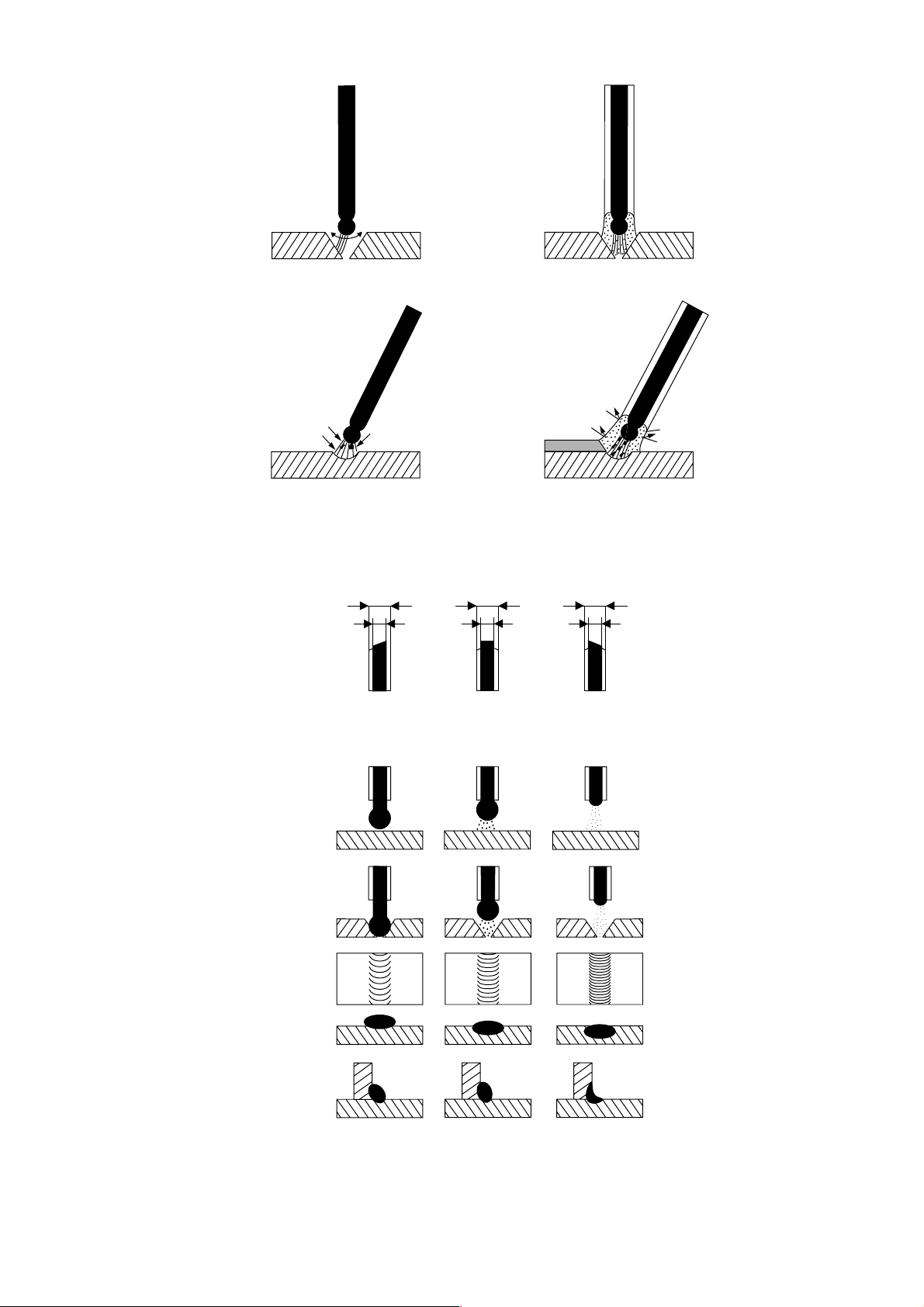
3.1.2Function of the Stick Electrode Coating
Stabilization of the
arc and lonization
of the arc space
bare
electrode
coated
electrode
unstable
arc
Protection of the weld
metal from atmospheric
oxygen and nitrogen
bare
electrode
This protection is achieved by the generation of shielding gases and slag during the
melting of the electrode.
Compensation of alloy burn-off.
Stick Electrodes According to DIN 1913
Coating thickness
D
d
stable
arc
coated
electrode
slag
DD
dd
shielding gas
Material transfer
Gap bridging ability
Weld seam appearance
Penetration depth
Types of Coating
A acid coated
R rutile light and medium coating
RR rutile heavy coating
AR rutile acid coating
C cellulose coating
light
D = 1.2 · d
medium
D > 1.2 · d
=
but < 1.55 · d
heavy
D > 1.55 · d
R(C) rutile cellulose medium coating
RR(C) rutile cellulose heavy coating
B basic coating
B(R) basic coating with non-basic proportions
RR(B) rutile basic heavy coating
15
Page 6

3.1.3Classification of Stick Electrodes
according to Table 3 of DIN 1913
Code for Welding Position
according to Table 4 of DIN 1913
Grade
2
3
4
5
6
7
8
9
10
11
12
Stick Electrode
Type
A 2
R 2
R 3
R(C) 3
C 4
RR 5
RR(C) 5
RR 6
RR(C) 6
A7
AR 7
RR(B) 7
RR 8
RR(B) 8
B 9
B(R) 9
B 10
R(R) 10
RR 11
AR 11
B 12
B(R) 12
Coating
Thickness
light
medium
heavy
(high-
performance
electrodes)
Weld
Position
1
2 (1)
1
2
1
2
1
2
1
2
4 (3)
Code Weld Position Code Letter For
Welding Position
1 all w, h, hü, s, f, q, ü
2 all except vertical-down w, h, hü, s, q, ü
3 gravity position w
fillet weld
gravity position w
horizontal h
4 gravity position w
3.1.4Selecting suitable Electrodes for a Welding Task
Component
Welding Task
out-of position
welding of butt and
fillet welds on thinwalled extrusion
horizontal or gravity
position fillet welds
on long beams with
"a" = 5 mm
gravity position
double-V welds on
thick plate tow bars
out-of-position fillet
welds on bracket of
10 mm thick plate
Stick Electrode Type
RR 6
RR 8
RR 11
AR 11
B 10
RR(B) 7
RR(B) 8
out-of-position butt
welds on pipelines
16
weld 1:
C 4
Page 7

Stick electrodes can be classified according to their coating as under:
Type Code
Type
Coating
Characteristics
O
Bare Electrode
finely distributed arc
stabilizers in the
electrode material
OO
Flux-Core Electrode
arc stabilizers rolled
into the electrode's
core
N
Titania Oxide Type
high contens of
titanium oxide
Acid-Coated Type
high contents of
heavy metal oxides
Type of Slag
Slag Removal Ability
minimal slag shallow
minimal slag average to deep
porous, even slag
blanket
easily removed
porous, even slag
blanket
Penetration Depth
Gap Bridging Ability
excellent
excellent
average
good to excellent,
depending on
coating thickness
deep
average
tion
more difficult to weld
than any other stick
electrode
slightly easier to
weld than bare
electrodes
weldability of fillet
welds improves with
increasing coating
thickness
weldability of fillet
welds improves with
increasing coating
thickness
very high deposition
rate, minimal heat
stress, little heat
distortion
good deposition
rate, minimal heat
stress, little weld
distorition,
especially for root
welds
general purpose
electrodes, for
steels sensitive to
welding conditions,
for thin plate
for steels sensitive
to welding
conditions, requires
good weld
preparation
Weld AppearanceCharacteristicsElectrode Manipula-
convex, coarsely
rippled
convex
coarsely rippled
slightly convex to
flat, finely to
medium-coarsely
rippled
flat, finely rippledEs
Ox
Iron Oxide Type
high contents of iron
oxides
Kb
Basic LowHydrogen Type
high contents of
calcium or other
alkaline carbonates
Ze
Cellulose Type
high contents of
organic components
tight slag blanket of
evenly distributed
thickness
very easily
thick slag blanket
fair
minimal, often
quickly solidifying
thin slag blanket
easy
shallow
very poor
medium
good
deep
very good
good weldability,
fillet welds in gravity
position only
handling requires
some practice, in
particular when
setting electrode to
and removing from
weld
good handling as
only minimal slag,
heavy fume
generation
for unalloyed lowcarbon steels,
requires good weld
preparation
particularly suitable
for thick plate and
rigid assemblies, for
high-carbon steels,
for thermo steels
for out-of-position
welding
concave, very finely
rippled
slightly convex,
medium-coarsely
rippled
slightly convex,
rippled
In addition to the electrodes types shown in the above table there are several special types available coded SO. Cast
iron electrodes, for example, fall into this class.
When buying Kb and So type electrodes make sure they are suitable for AC current. As far as the quality grades are
concerned, a higher number indicates a better grade quality. For common low-carbon steels grades 7 - 9 are best
suitable.
The last letter of the code shown on the stick electrode indicates the coating thickness.
d = light coating
m = medium coating
s = heavy coating
17
Page 8
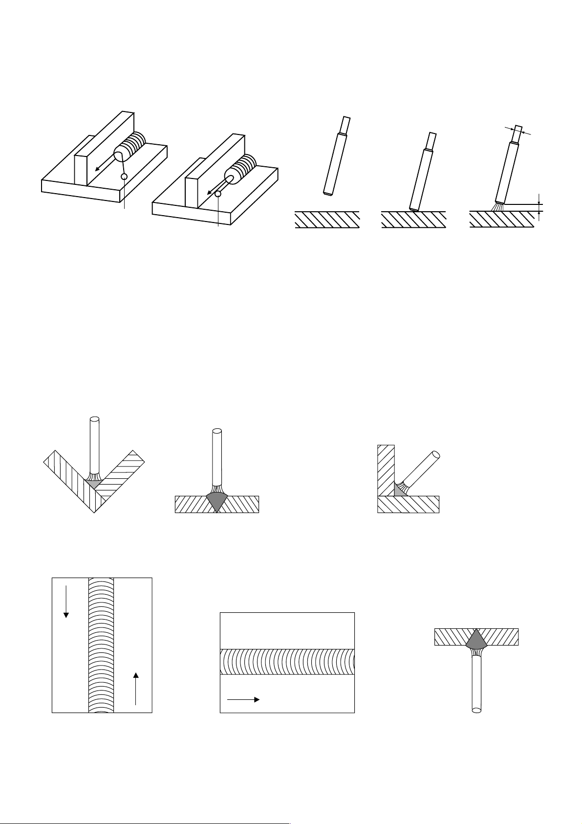
3.1.5Arc Starting and Arc Burning
Arc Strike
Always start the arc in the welding groove.
When the arc is stable weld over the arc strike and melt for good fusion, otherwise there is a risk of cracking.
Arc starting
sequence
d
wrong
arc strike
correct
arc strike
open-circuit voltage
Short-circuit voltage
3 to 5 V
working voltage
20 to 30 V
Arc Length
The arc length "a", that is the distance between the stick electrode and the work, should be:
with stick electrodes of coating type R, RR, A, C = 1.0xd,
with stick electrodes of coating type B = 0.5xd,
Too long an arc reduces the penetration, increases the arc blow effect and, particularly with basic coated stick
electrodes, causes a porous weld seam.
3.1.6Welding Positions According to DIN 1921
ww
a
w = gravity position
f
s
s = vertical-up position
f = vertical-down position
q
q = horizontal-vertical position
h
h = horizontal position
ü
ü = overhead position
18
Page 9

4 Welding Hints
Because of the multitude of and great differences in the important points for welding only the very basic
operations for the most common electrodes for low-carbon steels, the Ti-type electrode, are introduced here.
In the case that other electrodes have to be used, the electrode manufacturers supply upon request all relevant
information for the type of special electrode to be used.
Always make some trial welds on scrap material. Select electrode diameter and welding current as per Table 1.
Attach earth clamp to work piece and place electrode into electrode holder as described earlier. Now hold the
electrode tip approx. 2 cm / 1 inch above the starting point of your welding seam. Hold the welding shield in front
of your face and draw the electrode with a short stroke along the groove. Through the welding shield you watch
the arc, keeping it to a length of 1 to 1.5 times the electrode diameter.
wrong
arc too long
(Pic. 3)
correct
approx. 1 - 1.5 the electrode-Ø
(Pic. 4)
The correct arc length is important for a good weld, because with too short or too long an arc both welding current
and working voltage change. A low working voltage causes insufficient penetration. Too high or too low welding
current gives a poor welding seam. Too long an arc does not sufficiently melt the parent material, resulting in
high spatter losses. Also the air, with its detrimental substances like hydrogen and nitrogen, may get access to
the weld pool.
For a good weld the work angle of the electrode (or electrode inclination angle) is of substantial importance. The
inclination should be 70° - 80° to the welding direction. With the work angle too steep slag will run under the weld
pool, too flat an work angle causes the arc to spatter, in both cases the result is a porous, weak welding seam
(see pictures 5 - 7).
wrong
welding direction
> 80°
wrong correct
welding direction
welding direction
< 70°
70-80°
(Pic. 5)
(Pic. 6)
(Pic. 7)
The welder has to keep the arc at the same length, that is the electrode burn-off is compensated by feeding the
electrode into the weld. At the same time the welder has to watch the weld pool for even penetration and width.
Welding is always done from left to right (backhand welding).
At the end of the welding seam the electrode can not simply be lifted or pulled from the weld, this creates porous
end craters, which weaken the weld. To correctly terminate a weld the electrode is held for a short moment at
the end of the weld seam, then lifted in an arc over the just laid weld.
wrong
(Pic. 8)
correct
(Pic. 9)
Remove slag only after it has cooled down and is no longer glowing.
If an interrupted weld is to be continued, the slag at the end of the already finished weld must be removed. Then
the arc can be started either in the groove or on the weld, as described earlier, and then moved to the end of
the weld, which has to be thoroughly melted for good fusion. Welding is then continued normally.
19
Page 10
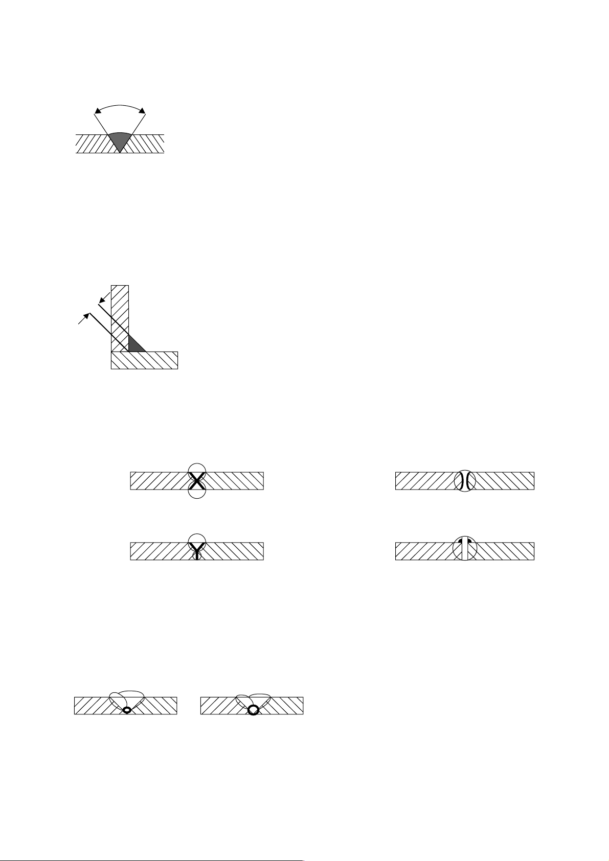
4.1 Weld Types
For Butt Welds the work piece edges should be bevelled to approx. 30°, which gives a groove angle of 60°
(Pic. 10).
The root opening between the two work pieces should be 2 - 3 mm.
60°
(Pic. 10)
For Fillet Welds "a" is the throat width size. The throat width should be at least x 0.7 the plate thickness of the
thinner plate.
a
(Pic. 11)
Other weld types:
x-weld
y-weld Flange weld
A joint weld must always have a good fusion at the root.
wrong
correct
J-weld
(Pic. 12)
Let weld cool down in the ambient air, do not quench.
(Pic. 13)
20
Page 11

4.2 Weld Flaws and possible Causes - Shown on Fillet Welds
Weld Undercut
Welding current to high
Electrode work angle too steep
Arc too long
End Crater
Electrode removed too quickly
from the weld pool, particularly
with high welding currents risk
of shrinkage cracking
Slag Inclusion
Welding current too low
Welding speed to high
Welding over slag on multilayer welds
Gas Inclusion
Work surface not clean
(rust, grease, paint)
Arc to long
Basic coated electrodes not
sufficiently dried
5 Accessories and Accessory Maintenance
Connecting Welding Cables to the Welding
Power Source
Weld Toe Cracks
Material sensitive to welding
conditions
Weld cooled down too fast after
welding
Root Flaw
Slag entering root area
because distance too great
Connecting (Extending) Welding Cables
Ring tongue terminal soldered, crimped, clamped
Fully Insulated Electrode Holder Connection of Welding Cables to the Work Piece
spring
handle
Replace broken insulating parts at once!
Attach earth clamp as close as possible to the weld. Structural components, beams, pipes or rails should not be used
for earth conducting if they are not the actual work piece.
hand lever
insulated jaws
Insulate screw joint terminal with rubber bush or heatshrinkable sleeve
Clean work piece surface for good conduction
21
Page 12

6 Wiring Diagrams
6 Schaltpläne
6 Schémas électriques
6 Schakelschema's
III
400 V
230 V
N
L1
L2
PE
CEE Plug
3P+N+PE
400 V
Contacts
N - N
L1 - L1
L2 - L2
N
L1
L2
Red Light
CEE Adapter
3P+N+PE
Schwitch Positions
400 V
On
OFF
OFF
0
ON
ON
ON
Plug
230 V
230 V
OFF
OFF
ON
SB 160 C (230/400 V)
Transformer
240V
Fan
Thermo
switch
Control
light
N
L1
PE
240V 0
Voltage selector switch
42
SB 200 CT (240 V)
Page 13

III
400 V
230 V
N
L1
L2
PE
CEE Plug
3P+N+PE
400 V
Contacts
N - N
L1 - L1
L2 - L2
N
L1
L2
Red Light
CEE Adapter
3P+N+PE
Schwitch Positions
400 V
On
OFF
OFF
0
ON
ON
ON
Plug
230 V
230 V
OFF
OFF
ON
SB 200 CT (230/400 V)
43
Page 14

Szczecinski; (+48) 91 - 5 78 11 95; (+48) 91 - 5 78 07 76;
serwis@metabo.pl
10-12; Apartado 53; 7000-171 Evora Codex; (+351) 266 - 74 93 00;
(+351) 266 - 74 93 09; bolas@mail.telepac.pt
65; ganesh@gulfincon.com
Apartado 342, Zona 9-A; Panam· ; (+507) 2 23 77 05; (+507) 2 69 18 66;
germante@cableonda.net
BIJL STREET; MEADOWDALE - Germiston; Johannesburg; (+27) 11 -
372 - 96 00; (+27) 11 - 453-41 63; ebotha@metabo.co.za
Santo Domingo; (+1) 809 - 531 50 80; (+1) 809 - 531 53 38;
jgarcia@agroindustrialferretera.com
(+40) 1 - 3 20 31 41; (+40) 1 - 3 20 31 42; agent@dial.kappa.ro
198 43 14/198 17 13; (+7) 095 - 198 43 14; metabo_service@mail.ru
) 52 - 3 54 34 44; (+41) 52 - 3 54 34 45; service@metabo.ch
Number One Building; Singapore 408563; (+65) 7 48 28 66; (+65) 7 45 38
72; sales@homely.com.sg
20; (+386) 61 - 1 68 16 16; metabo@dilex.si
263-1 Ipchung-Dong, Chung-Gu; Seoul; (+82) 2 - 22 76 09 14/5; (+82) 2 -
2 78 62 62; kwlee@metabokorea.co.kr
West Indies; Santa Lucia; (+1)758 - 452-99 14; (+1)758 - 452-99 15;
eurotools@candw.Lc
3566; Postal Code 112; Ruwi; (+968)70 31 70; (+968)70 83 05;
sjuma@email.com
10 06 60; (+46) 36 - 16 07 54; mwidell@metabo.dk
Halmstad; (+46) 35 - 154400; (+46) 35 - 104835; bo.rosenbaum@hdf.se
Pomprab Bangkok 10100; (+66) 2 - 3 28 11 89; (+66) 2 - 3 28 13 04;
vinai@ssm.co.th
1 - 25 83 92; (+216) 1 - 35 18 45; equipement-moderne@planet.tn
212 - 2 56 49 50; (+90) 212 - 2 38 98 26; elalet@burla.com
Opolcheniaya; 03 151 Kiev; (+380) 44 - 2 45 94 34; (+380) 44 - 2 45 93
65; comserv@ukrnet.net
6 - 533 05 51 ; (+971) 6 - 533 73 68; sedana@emirates.net.ae
Principal II, Piso 4; Caracas 1071; (+58) 212 - 2 37 30 22; (+58) 212 - 2 39
23 65; masmuss@olycopia.com
Ward 12; Tan Binh District; Ho Chi Minh City; (+84) 8 - 811 74 54; (+84) 8
- 811 63 38; TVTLinh@hcm.fpt.vn
Polska; Metabo Polska Sp. z o.o.; Gdynska 28; ; 73-110 Stargard
Portugal; BOLAS-Maq. e Ferramentas de Qualidade, S.A.; Rua B, Lotes 8-
Qatar; Gulf Incon; P.O.Box 4076; ; Doha; (+974) 4 68 35 11; (+974) 4 68 40
Rep. de Panam·; G erman-Tec (Panam·) S.A.; Via Argentina 46-70;
Republic of South Africa; Metabo Power Tools SA (Pty.) Ltd.; 165 Van DER
Republica Dominicana; Agroindustrial Ferretera S.A.; Av. Luperon No. 42; ;
Rumania; Agent Trade S.R.L.; Splaiul Unlrii 235-237; ; 74299 Bucuresti 3;
Russia; OOO ITA-Strojinkom; Uliza Alabjana 3; ; 125057 Moskau; (+7) 095 -
Schweiz; Metabo (Schweiz) AG; Lindauerstr. 17; ; 8317 Tagelswangen; (+41
Singapore; HOMELY HARDWARE PTE LTD; No. 1 Ubi Crescent #01-01;
Slovenia; Dilex d.o.o.; Ogrinceva 17; ; 1000 Ljubljana; (+386) 61 - 1 68 16
South Corea; Metabo-Korea Co. Ltd.; Room No. 101, Daesung Building;
St. Lucia; Eurotools Int`l Ltd; P.O.Box RB 2484; Rodney Bay, Gros Islet,
Sultanate of Oman; AHMED RAMADHAN JUMA & CO.L.L.C.; P.O. Box
Sverige; Metabo Sverige AB; Skifferv‰gen 6; ; 553 03 Jˆ nkˆ ping; (+46) 36 -
Sverige; HDF - Bolagen AB ; Svarvaregatan 5; P.O.Box 525; 30180
Thailand; SSM - Sri Siam Mongkol Co., Ltd; 1570-1576 Krung Kasem RD.; ;
Tunesia; L¥Equipment Moderne; 86, Ave. de Carthage; ; 1000 Tunis; (+216)
Turkey; Burla A.S.; Voyvoda Cad. 61-65; ; 80003 Karakˆ y-Istanbul; (+90)
Ukraine; Comservice; Ukraian-Russian Joint Venture 2; Narodnogo
United Arab Emirates; Sedana Trading Co; P.O. Box 1919; ; Sharjah; (+971)
Venezuela; OLY-COPIA C.A.; 3 ra Transversal Los Ruices ; Edificio
Vietnam; HUU HONG MACHINERY CO., LTD.; 157-159 Xuan Hong Street,
Estate; Southampton / SO 16 OYT; (+44) 2380 - 73 20 00; (+44) 2380 -
74 75 00; info@metabo.co.uk
Ciudad, 01009; (+502) 3 32 47 24; (+502) 3 32 47 81;
almpalma@amigo.net.gt
Cheung Sha Wan Road; Kowloon / Hong Kong; (+852) 29 26 22 00;
(+852) 28 82 19 78; rileytam@mail.jebsen.com.hk
(+354) 5 641135; asborg@centrum.is
Complex; Ambethan Road, Kharabwadi; Chakan, Tal.: Khed, Dist.-
Pune(Pin410 501); (+91) 213 - 55 22 03; (+91) 213 - 55 21 61;
Kencana No. 1; Meruya - Kembangan; Jakarta 11610; (+62) 21 - 5 82 82
82; (+62) 21 - 5 82 55 88; kawanlama@kawanlama.com
Road; 33033 Haifa; (+972) 4 - 8 64 04 69; (+972) 4 - 8 67 18 03;
dubovsky@matav.net.il
Milanese (MI); (+39) 02 - 52 77 71; (+39) 02 - 55 60 03 22;
cstechel@stechel.it
0063; (+81) 4 - 28 77 05 06; (+81) 4 - 28 77 05 07;
Center; Amman 111 18; (+962) 6 - 465 56 80; (+962) 6 - 464 54 39;
jsakkab@nta.com.jo
Road, Kilo 9; P.O.Box 11429; Jeddah 21453; (+96) 62 - 6 82 04 58; (+96)
62 - 6 91 12 67; sitaco@sitaco.com.sa
663 SAFAT; 13007 State of Kuwait; (+965) 47 47 137; (+965) 47 47 945;
Alsayer_electro@hotmail.com
56100 Kuala Lumpur; (+60) 3 - 92002966 / 92003966; (+60) 3 - 92007599;
finetools@pd.jaring.my
Sentul; ; 51700 Kuala Lumpur; (+60)3 - 6 18 88 88; (+60)3 - 6 17 66 16;
11; (+356) 43 54 24; (+356) 41 73 58; gtimports@mail.global.net.mt
525 14 09; STAF@toptechnology.mr
2 12 64 05; (+230) 2 10 74 57; dema@intnet.mu
(+212) 2 31 25 06; (+212) 2 - 31 24 62;
(+31) 3462 - 6 42 44; (+31) 3462 - 6 35 54; verkoop@metabo.nl
668; 98845 NoumÈa; (+687) 27 20 02; (+687) 27 30 94;
szemmelveisz@canl.nc
Christchurch; (+64) 3 - 36 55 931; (+64) 3 - 36 55 932;
hamish@metabo.co.nz
Great Britain; Metabo (UK) Ltd.; 25 Majestic Road ; Nursling Industrial
Guatemala; Almacen la Palma S.A.; 2a Calle 4-38, Zona 9; ; Guatemala
Hong Kong; Jebsen & Co. Ltd. ; 9/F, Jebsen Motor Group Building; 924-926
Iceland; ASBORG S.F.; Smidjuvegi 11; ; 200 Kopavogi; (+354) 5 641212;
India; Metabo Power Tools PVT Ltd.; Plot No. 40, WMDC Industrial
Indonesia; P.T. Kawan Lama Sejahtera pt; Gedung Kawan Lama Jl. Puri
Israel; Proter + Cohn Ltd; Technical Supply P.O.Box 33215 / 3; Haatzmaut
Italia; Carlo Stechel & Figli S.rl; Via Buozzi, 22; ; 20 097 San Donato
Japan; Metabo Japan Co., Ltd.; 5-1024-3, Baigou, Ohme-city; ; Tokyo 198-
Jordan; Newport Trading Agency; P.O.Box 6166 / 151 Hashimi Str.; City
Kingdom of Saudi Arabia; Saudi Industrial Tools Corporation; Madinah
Kuwait; Naser Moh. Al-Sayer ; Gen. Trading & Contracting Co.; P.O. Box
Malaysia; Finetools SDN BHD; No. 7 Jalan 1/92C; Batu 3 1/4 Jalan Cheras;
Malaysia; LINTREX (Malaysia) SON: BHD.; 68100 BATU Caves, Box S 24
Malta; G + T Imports Limited; Metabo Shop, Birkirkara By-Pass; ; Iklin BZN
Mauritanie; S.T.A.F; B.P.: 40246; ; Nouakchott; (+222) 525 33 85; (+222)
Mauritius; Dema - Supplies Ltd.; 2A Deschartres Street; ; Port Louis; (+230)
Morocco; StÈ Yyes Rouger; 20 Bd. Ibn Tachfine; ; 20300 Casablanca;
Nederland; Metabo Nederland b.v.; Postbus 180; ; 3620 AD Breukelen;
New Caledonia; Ets. Szemmelveisz; 3, Rue Fernand Forest; Boite Postale
New Zealand; Tooline Limited; 50 Disraeli Street; P.O. Box 798;
55 55; (+47) 33 - 44 55 50; psteingrimsen@metabo.no
Norway; Metabo Norge AS; Postboks 1296; ; 3205 Sandefjord; (+47) 33 - 44
Sad; (+38) 12 15 28 56; (+38) 12 15 24 57; woby@Eunet.yu
Yugoslavia; WHM WOBY HAUS MARKT; Brace Ribnikara 55; ; 21000 Novi
AD/AC (EB)
(+595) 981 - 43 15 13; (+595) 21 - 33 36 77; taguato@conexion.com.py
Quezon City; (+63) 2 - 3 63 01 59; (+63) 2 - 3 61 48 41;
Paraguai; Taguato S.A.; Avda.Gra.Santos No. 1948/Tte. Garay; ; Asuncion;
nancytanyu@speedsurf.pacific.net.ph
Philippines; Mach Tools Inc.; 185 A & B del Monte Avenue; ; Manresa,
62; (+355) 42 - 3 30 62; abeqiri@t-online.de
Rouiba; (+213) 21 - 85 49 05; (+213) 21 - 85 57 72;
Ciudadela - Buenos Aires; (+54) 11 - 44 88 - 9180; (+54) 11 - 44 88 - 39
89; info@metabo.com.ar
3179; (+61) 3 - 97 65 01 99; (+61) 3 - 97 65 01 89; sales@metabo.com.au
(+973)40 43 23; almahros@batelco.com.bh
(+880) 2 - 9 56 94 77 / 9 55 04 00;
- 4 67 32 10; (+32) 2 - 4 66 75 28; general@metabo.be
51 - 302 718; (+387) 51 - 785 708; agrokombinat@blic.net
Diadema - Sao Paulo - Cep 09911-630; (+55) 11 - 40 51 - 25 11; (+55) 11
- 4056 - 4152; metabo@metabo.com.br
Labem; (+420) 202 - 80 44 55; (+420) 202 - 80 44 56;
mlanda@metabo.cz
11; (+56) 2 - 6 99 04 85; empresa@nordchil.cl
2400; San JosÈ; (+506) 2 32 91 11; (+506) 2 32 93 53;
webmaster@capris.co.cr
Ave; 1641 Lefkosia, Cyprus; (+357) 2 - 34 95 77; (+357) 2 - 34 93 94;
condam@spidernet.com.cy
- 31 34 00; (+45) 43 - 31 34 01; scarstensen@metabo.dk
33 34 56; 0180 -3 33 34 57; Ersatzteilverkauf@elektra-beckum.de
(+372) 620 11 12; mecro@mecro.ee
; Cairo; (+20)2 -25 91 32 77; (+20)2 -25 90 02 23; eea@eea.co.eg
Cuscatancingo; San Salvador; (+503) 2 - 38 47 65; (+503) 2 86 52 36;
metabo1@telesal.net
C/Forjadores, 12; 28660 Boadilla del Monte (Madrid); (+34) 91 - 6 32 47
40; (+34) 91 - 6 32 41 47; wbuhrle@metabo.es
27 58; (+251) 1-51 50 82; sutco@telecom.net.et
804861; (+358) 9 - 803 9485; reijo.helenius@nofa.fi
33 37 57 19; (+33)2 33 37 72 25;
Country; Company; Address 1; Address 2; City; Phone; Fax; E-mail
Albania; Extra Industrial Goods; Rl. Fadil Rada 88; ; Tirana; (+355) 42 - 3 30
Algerie; Haddad Equipement Professione; 98 A, Site du LycÈe; ; 16012
Argentina; Metabo Argentia S.A.; Teniente Gral. Richieri 4773; ; 1702 -
Australia; Metabo Pty. Ltd; 10 Dalmore Drive; ; Scoresby, Melbourne, Vic.
Bahrain; AL-MAHROOS; P.O. Box 65, Manama; ; Bahrain; (+973)40 06 96;
Bangladesh; East Bengal Impex; 175, Nawabpur Road (4th floor); ; Dhaka; ;
Belgique; Metabo Belgium; ¥t Hofveld 3 - 5; ; 1702 Groot Bijgaarden; (+32) 2
Bosnia and Herzegovina; Agrarkombinat; Majevicka 1; ; Banja Luka; (+387)
Brazil; Metabo do Brasil Ltda.; Rua Guicurus 306 - Vila Conceicao; ;
Ceska Republica; Metabo s.r.o; Kralovicka 544; ; 250 01 Brandys nad
Chile; Nordchil S.A.; San Diego 895; ; Santiago de Chile; (+56) 2 - 6 72 29
Costa Rica; Capris S.A.; Frente la Imprenta Nacional, La Uruca; P.O. Box 7-
Cyprus; Med Marketing Ltd. (eurotools); P.O. Box 27017; 17, Digenis Akritas
Danmark; Metabo Danmark A/S; Helgeshoj AllÈ 12; ; 2630 Tastrup; (+45) 43
Deutschland; Elektra-Beckum AG; Daimlerstr. 2; ; 49716 Meppen; 0180 - 3
Eestlane; A/S MECRO; Peterburi tee 44; ; 11415 Tallinn; (+372) 620 11 11;
Egypt; EGYPTIAN ENGINEERING AGENCIES; 16 Naguib El-Rihani Street;
El Salvador; Metabo S.A. de C.V.; Colonia Santa Clara, Pasaje C No. 20;
Espana; Herramientas Metabo S.A.; PolÌgono Ind. Prado del Espino;
Ethiopia; SUTCO Pvt. Ltd. Co.; P.O. Box 17924; ; Addis Ababa; (+251) 1-51
Finland; NOFA O.Y.; Hannuksentie 1; O.O. Box 28 ; 02270 Espoo; (+358) 9-
House; P.O. Box 1783; Accra; (+233) 21 - 66 39 94; (+233) 21 - 78 02 90;
France; LUREM MACHINES A BOIS S.A.; BP 1 ; ; 61700 Domfront; (+33)2
Ghana; Emmnock Tradingcompany Ltd.; Knutsford. Avenue opp. Morocco
 Loading...