

Page 1
Designed for operating in USA & Canada only.
When this product is used in areas other than the USA & Canada,
we cannot guarantee the product quality and performance.
Model
Modèle
Modelo
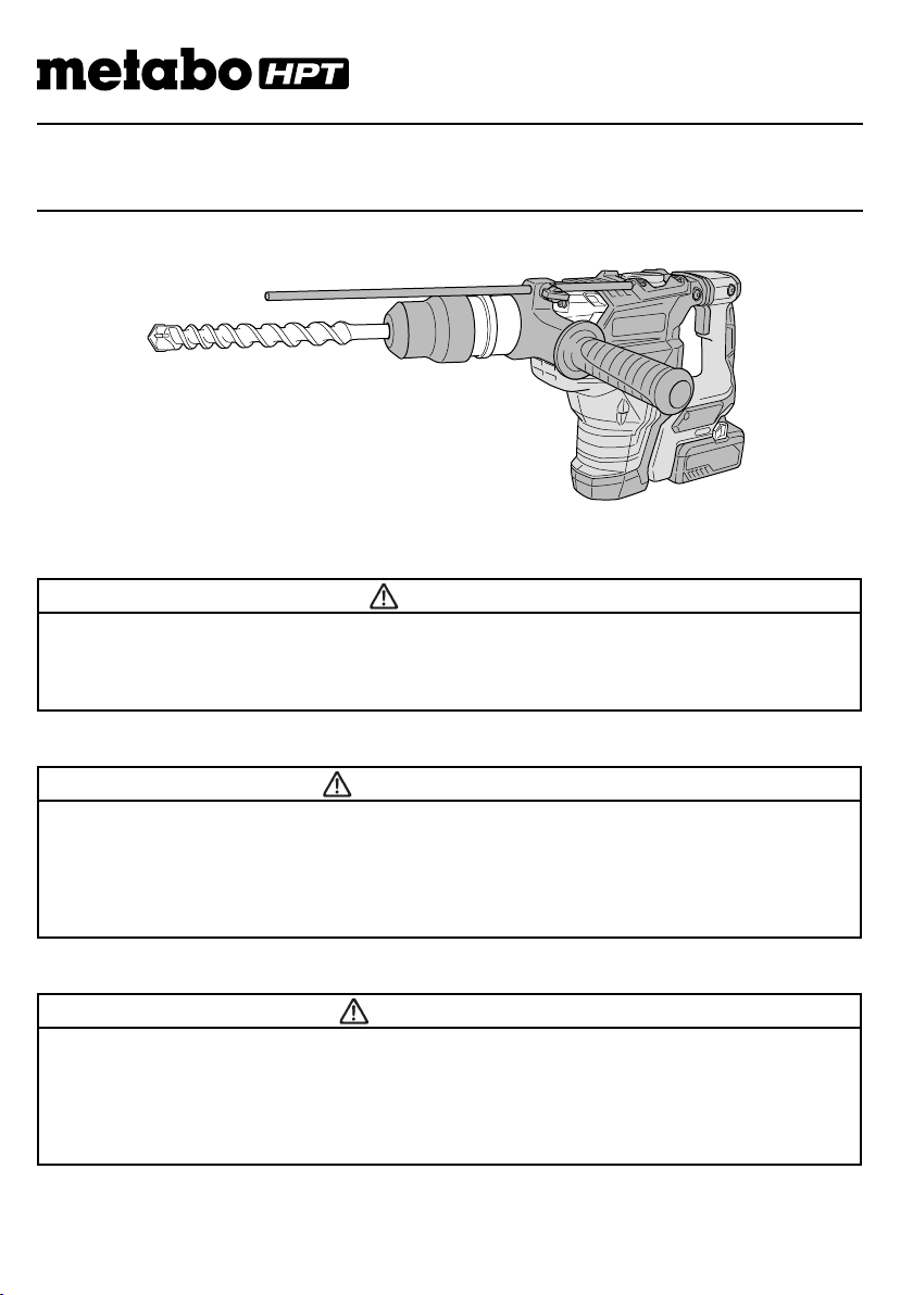
DH 36DMA
Cordless Rotary Hammer
Marteau rotatif sans fi l
Martillo perforador inalámbrico
SAFETY INSTRUCTIONS AND INSTRUCTION MANUAL
WARNING
IMPROPER OR UNSAFE use of this power tool can result in death or serious bodily injury!
This manual contains important information about product safety. Please read and understand
this manual BEFORE operating the power tool. Please keep this manual available for other
users and owners before they use the power tool. This manual should be stored in safe place.
INSTRUCTIONS DE SECURITE ET MODE D’EMPLOI
AVERTISSEMENT
Une utilisation INCORRECTE OU DANGEREUSE de cet outil motorisé peut entraîner la mort
ou de sérieuses blessures corporelles!
Ce mode d’emploi contient d’importantes informations à propos de la sécurité de ce produit.
Prière de lire et de comprendre ce mode d’emploi AVANT d’utiliser l’outil motorisé. Garder ce
mode d’emploi à la disponibilité des autres utilisateurs et propriétaires avant qu’ils utilisent
l’outil motorisé. Ce mode d’emploi doit être conservé dans un endroit sûr.
INSTRUCCIONES DE SEGURIDAD Y MANUAL DE INSTRUCCIONES
ADVERTENCIA
¡La utilización INAPROPIADA O PELIGROSA de esta herramienta eléctrica puede resultar
en lesiones de gravedad o la muerte!
Este manual contiene información importante sobre la seguridad del producto. Lea y
comprenda este manual ANTES de utilizar la herramienta eléctrica. Guarde este manual
para que puedan leerlo otras personas antes de utilizar la herramienta eléctrica. Este manual
debe ser guardado en un lugar seguro.
Page 2
English
IMPORTANT SAFETY INFORMATION
Read and understand all of the safety precautions, warnings and operating instructions in the Instruction Manual before
operating or maintaining this power tool.
Most accidents that result from power tool operation and maintenance are caused by the failure to observe basic safety
rules or precautions. An accident can often be avoided by recognizing a potentially hazardous situation before it occurs,
and by observing appropriate safety procedures.
Basic safety precautions are outlined in the “SAFETY” section of this Instruction Manual and in the sections which
contain the operation and maintenance instructions.
Hazards that must be avoided to prevent bodily injury or machine damage are identifi ed by WARNINGS on the power
tool and in this Instruction Manual.
NEVER use this power tool in a manner that has not been specifi cally recommended by metabo HPT.
MEANINGS OF SIGNAL WORDS
WARNING indicates a potentially hazardous situations which, if ignored, could result in death or serious injury.
CAUTION indicates a potentially hazardous situations which, if not avoided, may result in minor or moderate injury, or
may cause machine damage.
NOTE emphasizes essential information.
SAFETY
GENERAL POWER TOOL SAFETY WARNINGS
WARNING
Read all safety warnings and all instructions.
Failure to follow the warnings and instructions may result in electric shock, fi re and/or serious injury.
Save all warnings and instructions for future reference.
The term “power tool” in the warnings refers to your mains-operated (corded) power tool or battery-operated
(cordless) power tool.
1) Work area safet y
a) Keep work area clean and well lit.
Cluttered or dark areas invite accidents.
b) Do not operate power tools in explosive
atmospheres, such as in the presence of
fl ammable liquids, gases or dust.
Power tools create sparks which may ignite the
dust or fumes.
c) Keep children and bystanders away while
operating a power tool.
Distractions can cause you to lose control.
2) Electrical safety
a) Power tool plugs must match the outlet.
Never modify the plug in any way.
Do not use any adapter plugs with earthed
(grounded) power tools.
Unmodifi ed plugs and matching outlets will reduce
risk of electric shock.
b) Avoid body contact with earthed or grounded
surfaces such as pipes, radiators, ranges and
refrigerators.
2
There is an increased risk of electric shock if your
body is earthed or grounded.
c) Do not expose power tools to rain or wet
conditions.
Water entering a power tool will increase the risk
of electric shock.
d) Do not abuse the cord. Never use the cord
for carrying, pulling or unplugging the power
tool.
Keep cord away from heat, oil, sharp edges or
moving parts.
Damaged or entangled cords increase the risk of
electric shock.
e) When operating a power tool outdoors, use
an extension cord suitable for outdoor use.
Use of a cord suitable for outdoor use reduces the
risk of electric shock.
f) If operating a power tool in a damp location
is unavoidable, use a residual current device
(RCD) protected supply.
Use of an RCD reduces the risk of electric shock.
Page 3

English
3) Personal safety
a) Stay alert, watch what you are doing and use
common sense when operating a power tool.
Do not use a power tool while you are tired
or under the infl uence of drugs, alcohol or
medication.
A moment of inattention while operating power
tools may result in serious personal injury.
b) Use personal protective equipment. Always
wear eye protection.
Protective equipment such as dust mask, non-skid
safety shoes, hard hat, or hearing protection used
for appropriate conditions will reduce personal
injuries.
c) Prevent unintentional starting. Ensure the
switch is in the off -position before connecting
to power source and/or battery pack, picking
up or carrying the tool.
Carrying power tools with your fi nger on the switch
or energising power tools that have the switch on
invites accidents.
d) Remove any adjusting key or wrench before
turning the power tool on.
A wrench or a key left attached to a rotating part of
the power tool may result in personal injury.
e) Do not overreach. Keep proper footing and
balance at all times.
This enables better control of the power tool in
unexpected situations.
f) Dress properly. Do not wear loose clothing or
jewellery. Keep your hair, clothing and gloves
away from moving parts.
Loose clothes, jewellery or long hair can be caught
in moving parts.
g) If devices are provided for the connection
of dust extraction and collection facilities,
ensure these are connected and properly
used.
Use of dust collection can reduce dust-related
hazards.
4) Power tool use and care
a) Do not force the power tool. Use the correct
power tool for your application.
The correct power tool will do the job better and
safer at the rate for which it was designed.
b) Do not use the power tool if the switch does
not turn it on and off .
Any power tool that cannot be controlled with the
switch is dangerous and must be repaired.
c) Disconnect the plug from the power source
and/or the battery pack from the power tool
before making any adjustments, changing
accessories, or storing power tools.
Such preventive safety measures reduce the risk
of starting the power tool accidentally.
d) Store idle power tools out of the reach of
children and do not allow persons unfamiliar
with the power tool or these instructions to
operate the power tool.
Power tools are dangerous in the hands of
untrained users.
e) Maintain power tools. Check for misalignment
or binding of moving parts, breakage of parts
and any other condition that may aff ect the
power tool’s operation.
If damaged, have the power tool repaired
before use.
Many accidents are caused by poorly maintained
power tools.
f) Keep cutting tools sharp and clean.
Properly maintained cutting tools with sharp
cutting edges are less likely to bind and are easier
to control.
g) Use the power tool, accessories and tool bits
etc. in accordance with these instructions,
taking into account the working conditions
and the work to be performed.
Use of the power tool for operations diff erent
from those intended could result in a hazardous
situation.
5) Battery tool use and care
a) Recharge only with the charger specifi ed by
the manufacturer.
A charger that is suitable for one type of battery
pack may create a risk of fi re when used with
another battery pack.
b) Use power tools only with specifi cally
designated battery packs.
Use of any other battery packs may create a risk of
injury and fi re.
c) When battery pack is not in use, keep it away
from other metal objects like paper clips,
coins, keys, nails, screws, or other small
metal objects, that can make a connection
from one terminal to another.
Shorting the battery terminals together may cause
burns or a fi re.
d) Under abusive conditions, liquid may be
ejected from the battery; avoid contact. If
contact accidentally occurs, fl ush with water.
If liquid contacts eyes, additionally seek
medical help.
Liquid ejected from the battery may cause irritation
or burns.
6) Service
a) Have your power tool serviced by a
qualifi ed repair person using only identical
replacement parts.
This will ensure that the safety of the power tool is
maintained.
3
Page 4
English
– WARNING –
To reduce the risk of injury, user must read
instruction manual.
WARNING:
Some dust created by power sanding, sawing,
grinding, drilling, and other construction activities
contains chemicals known to the State of California
to cause cancer, birth defects or other reproductive
harm. Some examples of these chemicals are:
●
Lead from lead-based paints,
●
Crystalline silica from bricks and cement and
other masonry products, and
●
Arsenic and chromium from chemically-treated
lumber.
Your risk from these exposures varies, depending on
how often you do this type of work. To reduce your
exposure to these chemicals: work in a well ventilated
area, and work with approved safety equipment, such
as those dust masks that are specially designed to
fi lter out microscopic particles.
SPECIFIC SAFETY RULES AND SYMBOLS
1. Wear ear protectors.
2. Use auxiliary handle(s), if supplied with the tool.
Loss of control can cause personal injury.
3. Hold power tools by insulated gripping surfaces
when performing an operation where the cutting
accessory may contact hidden wiring.
Cutting accessory contacting a “live” wire may make
exposed metal parts of the power tool “live” and could
give the operator an electric shock.
4. NEVER touch the tool bit with bare hands after
operation.
5. NEVER wear gloves made from materials likely to roll
up such as cotton, wool, cloth or string, etc.
6. ALWAYS attach the side handle and securely grip the
Rotary Hammer.
7. Never touch moving parts.
NEVER place your hands, fi ngers or other body parts
near the tool’s moving parts.
8. Never operate without all guards in place.
NEVER operate this tool without all guards or safety
features in place and in proper working order. If
maintenance or servicing requires the removal of a
guard or safety feature, be sure to replace the guard
or safety feature before resuming operation of the
tool.
4
Exposure to noise can cause hearing
loss.
9. Use right tool.
Don’t force small tool or attachment to do the job of a
heavy-duty tool.
Don’t use tool for purpose not intended —for
example— don’t use circular saw for cutting tree
limbs or logs.
10. Never use a power tool for applications other
than those specifi ed.
NEVER use a power tool for applications other than
those specifi ed in the Instruction Manual.
11. Handle tool correctly.
Operate the tool according to the instructions
provided herein. Do not drop or throw the tool.
NEVER allow the tool to be operated by children,
individuals unfamiliar with its operation or
unauthorized personnel.
12. Keep all screws, bolts and covers tightly in place.
Keep all screws, bolts, and plates tightly mounted.
Check their condition periodically.
13. Do not use power tools if the plastic housing or
handle is cracked.
Cracks in the tool’s housing or handle can lead to
electric shock. Such tools should not be used until
repaired.
14. Bits and accessories must be securely mounted
to the tool.
Prevent potential injuries to yourself or others. Bits
and accessories which have been mounted to the tool
should be secure and tight.
15. Keep motor air vent clean.
The tool’s motor air vent must be kept clean so that
air can freely fl ow at all times. Check for dust build-up
frequently.
16. Because the cordless tool operates by battery power,
be aware of the fact that it can begin to operate at any
time.
17. NEVER use a tool which is defective or operating
abnormally.
If the tool appears to be operating unusually, making
strange noises, or otherwise appears defective, stop
using it immediately and arrange for repairs by a
metabo HPT authorized service center.
18. NEVER leave tool running unattended. Turn power
off .
Don’t leave tool until it comes to a complete stop.
19. Carefully handle power tools.
Should a power tool be dropped or struck against
hard materials inadvertently, it may be deformed,
cracked, or damaged.
20. Do not wipe plastic parts with solvent.
Solvents such as gasoline, thinner benzine, carbon
tetrachloride, and alcohol may damage and crack
plastic parts. Do not wipe them with such solvents.
Wipe plastic parts with a soft cloth lightly dampened
with soapy water and dry thoroughly.
Page 5
English
21. ALWAYS wear eye protection that meets the
22. Do not use the product if the tool or the battery
terminals (battery mount) are deformed.
Installing the battery could cause a short circuit that
could result in smoke emission or ignition.
23. Keep the tool’s terminals (battery mount) free of swarf
and dust.
○
Prior to use, make sure that swarf and dust have not
collected in the area of the terminals.
○
During use, try to avoid swarf or dust on the tool from
falling on the battery.
○
When suspending operation or after use, do not leave
the tool in an area where it may be exposed to falling
swarf or dust.
Doing so could cause a short circuit that could result
in smoke emission or ignition.
24. ALWAYS be careful with buried object such as an
underground wiring.
Touching live wiring or electric cable with this tool may
result in electric shock.
Confi rm before use whether hidden objects are
present, such as electric cables within the wall, fl oor
or ceiling.
25. Defi nitions for symbols used on this tool
V .............volts
—
---
no ...........no load speed
---/min .....revolutions per minute
requirement of the latest revision of ANSI
Standard Z87.1.
........... direc t curre nt
IMPORTANT SAFETY INSTRUCTIONS
FOR BATTERY CHARGER
WARNING
Death or serious bodily injury could result from
improper or unsafe use of battery chargers.
To avoid these risks, follow these basic safety
instructions:
READ ALL INSTRUCTIONS
1. This manual contains important safety and operating
instructions for battery charger Model UC18YSL3.
2. Before using battery charger, read all instructions
and cautionary markings on (1) battery charger, (2)
battery, and (3) product using battery.
3. To reduce risk of injury, charge metabo HPT
rechargeable battery type BSL36B18 and BSL18
series . Other type of batteries may burst causing
personal injury and damage.
4. Use of an attachment not recommended or sold by
the battery charger manufacturer may result in a risk
of fi re, electric shock, or injury to persons.
5. To reduce risk of damage to electric plug and cord,
pull by plug when disconnecting battery charger.
6. Make sure cord is located so that it will not be stepped
on, tripped over, or otherwise subjected to damage or
stress.
7. An extension cord should not be used unless
absolutely necessary. Use of improper extension
cord could result in a risk of fi re and electric shock.
If extension cord must be used make sure:
a. That blades of extension cord are the same
number, size, and shape as those of plug on
battery charger:
b. That extension cord is properly wired and in good
electrical condition; and
c. That wire size is large enough for AC ampere
rating of battery charger as specifi ed in Table 1.
Table 1
RECOMMENDED MINIMUM AWG SIZE FOR
EXTENSION CORDS FOR BATTERY CHARGERS
AC Input Rating Amperes* AWG Size of Cord
Equal to or
greater than
0 2 18 18 18 16
2 3 18 18 16 14
3 4 18 18 16 14
but less
than
Length of Cord, Feet (Meter)
25 (7.5) 50 (15) 100 (30) 150 (45)
5
Page 6

English
* If the input rating of a battery charger is given in watts
rather than in amperes, the corresponding ampere
rating is to be determined by dividing the wattage
rating by the voltage rating–for example:
1,250 watts
125 volts
8. Do not operate battery charger with damaged cord or
plug-replace them immediately.
9. Do not operate battery charger if it has received a
sharp blow, been dropped, or otherwise damaged in
any way; take it to a qualifi ed serviceman.
10. Do not disassemble battery charger; take it to a
qualifi ed serviceman when service or repair is
required. Incorrect reassembly may result in a risk of
electric shock or fi re.
11. To reduce risk of electric shock, unplug charger from
receptacle before attempting any maintenance or
cleaning. Removing the battery will not reduce this
risk.
IMPORTANT SAFETY INSTRUCTIONS
FOR USE OF THE BATTERY AND
BATTERY CHARGER
You must charge the battery before you can use the power
tool. Before using the model UC18YSL3 battery charger,
be sure to read all instructions and cautionary statements
on it, the battery and in this manual.
REMEMBER: USE ONLY metabo HPT BATTERY TYPE
BSL36B18. OTHER TYPES OF BATTERIES MAY BURST
AND CAUSE INJURY!
Follow these instructions to avoid the risk of injury:
= 10 amperes
WARNING
Improper use of the battery or battery charger
can lead to serious injury. To avoid these injuries:
1. NEVER disassemble the battery.
2. NEVER incinerate the battery, even if it is damaged or
is completely worn out. The battery can explode in a
fi re.
3. NEVER short-circuit the battery.
4. NEVER insert any objects into the battery charger’s
air vents. Electric shock or damage to the battery
charger may result.
5. NEVER charge outdoors. Keep the battery away
from direct sunlight and use only where there is low
humidity and good ventilation.
6. NEVER charge when the temperature is below 14°F
(-10°C) or above 104°F (40°C).
7. NEVER connect two battery chargers together.
8. NEVER insert foreign objects into the hole for the
battery or the battery charger.
9. NEVER use a booster transformer when charging.
10. NEVER use DC power to charge.
11. NEVER store the battery or battery charger in places
where the temperature may reach or exceed 104°F
(40°C) such as inside metal box or car.
12. NEVER expose the battery or battery charger to rain
or wet conditions.
13. ALWAYS operate charger on standard household
electrical power (120 volts). Using the charger on any
other voltage may overheat and damage the charger.
14. ALWAYS wait at least 15 minutes between charges to
avoid overheating the charger.
15. ALWAYS disconnect the power cord from its
receptacle when the charger is not in use.
CAUTION ON LITHIUM-ION BATTERY
To extend the lifetime, the lithium-ion battery equips with
the protection function to stop the output.
In the cases of 1 to 3 described below, when using this
product, even if you are pulling the switch, the motor may
stop. This is not the trouble but the result of protection
function.
1. When the battery power remaining runs out, the motor
stops.
In such case, charge it up immediately.
2. If the tool is overloaded, the motor may stop. In this
case, release the switch of tool and eliminate causes
of overloading. After that, you can use it again.
3. If the battery is overheated under overload work, the
battery power may stop.
In this case, stop using the battery and let the battery
cool. After that, you can use it again.
Furthermore, please heed the following warning and
caution.
WARNING
In order to prevent any battery leakage, heat
generation, smoke emission, explosion and ignition
beforehand, please be sure to heed the following
precautions.
1. Make sure that swarf and dust do not collect on the
battery.
○
During work make sure that swarf and dust do not fall
on the battery.
○
Make sure that any swarf and dust falling on the power
tool during work do not collect on the battery.
○
Do not store an unused battery in a location exposed
to swarf and dust.
○
Before storing a battery, remove any swarf and dust
that may adhere to it and do not store it together with
metal parts (screws, nails, etc.).
2. Do not pierce battery with a sharp object such as a
nail, strike with a hammer, step on, throw or subject
the battery to severe physical shock.
6
Page 7

English
3. Do not use an apparently damaged or deformed
battery.
4. Do not use the battery in reverse polarity.
5. Do not connect directly to an electrical outlets or car
cigarette lighter sockets.
6. Do not use the battery for a purpose other than those
specifi ed.
7. If the battery charging fails to complete even when a
specifi ed recharging time has elapsed, immediately
stop further recharging.
8. Do not put or subject the battery to high temperatures
or high pressure such as into a microwave oven,
dryer, or high pressure container.
9. Keep away from fi re immediately when leakage or foul
odor are detected.
10. Do not use in a location where strong static electricity
generates.
11. If there is battery leakage, foul odor, heat generated,
discolored or deformed, or in any way appears
abnormal during use, recharging or storage,
immediately remove it from the equipment or battery
charger, and stop use.
12. Do not immerse the battery or allow any fl uids to fl ow
inside. Conductive liquid ingress, such as water, can
cause damage resulting in fi re or explosion. Store your
battery in a cool, dry place, away from combustible
and fl ammable items. Corrosive gas atmospheres
must be avoided.
CAUTION
1. If liquid leaking from the battery gets into your eyes,
do not rub your eyes and wash them well with fresh
clean water such as tap water and contact a doctor
immediately.
If left untreated, the liquid may cause eye-problems.
2. If liquid leaks onto your skin or clothes, wash well with
clean water such as tap water immediately.
There is a possibility that this can cause skin irritation.
3. If you fi nd rust, foul odor, overheating, discolor,
deformation, and/or other irregularities when using
the battery for the fi rst time, do not use and return it to
your supplier or vendor.
WARNING
If an electrically conductive foreign object enters the
terminals of the lithium ion battery, a short-circuit may
occur resulting in the risk of fi re. Please observe the
following matters when storing the battery.
○
Do not place electrically conductive cuttings,
nails, steel wire, copper wire or other wire in the
storage case.
○
Either install the battery in the power tool or store
by securely pressing into the battery cover until
the ventilation holes are concealed to prevent
short-circuits (See Fig. 3).
REGARDING LITHIUM-ION BATTERY
TRANSPORTATION
When transporting a lithium-ion battery, please observe
the following precautions.
WARNING
Notify the transporting company that a package
contains a lithium-ion battery, inform the company
of its power output and follow the instructions of the
transportation company when arranging transport.
●
Lithium-ion batteries that exceed a power output
of 100 Wh are considered to be in the freight
classifi cation of Dangerous Goods and will
require special application procedures.
●
For transportation abroad, you must comply with
international law and the rules and regulations of
the destination country.
●
If the BSL36B18 is installed in the power tool, the
power output will exceed 100 Wh and the unit
will be classifi ed as Dangerous Goods for freight
classifi cation.
Power Output
Wh
2 to 3 digit number
Fig. 1
SAVE THESE INSTRUCTIONS
AND
MAKE THEM AVAILABLE TO OTHER USERS
AND
OWNERS OF THIS TOOL!
7
Page 8
English
FUNCTIONAL DESCRIPTION
NOTE
The information contained in this Instruction Manual is designed to assist you in the safe operation and maintenance
of the power tool.
NEVER operate, or attempt any maintenance on the tool unless you have fi rst read and understood all safety
instructions contained in this manual.
Some illustrations in this Instruction Manual may show details or attachments that diff er from those on your own
power tool.
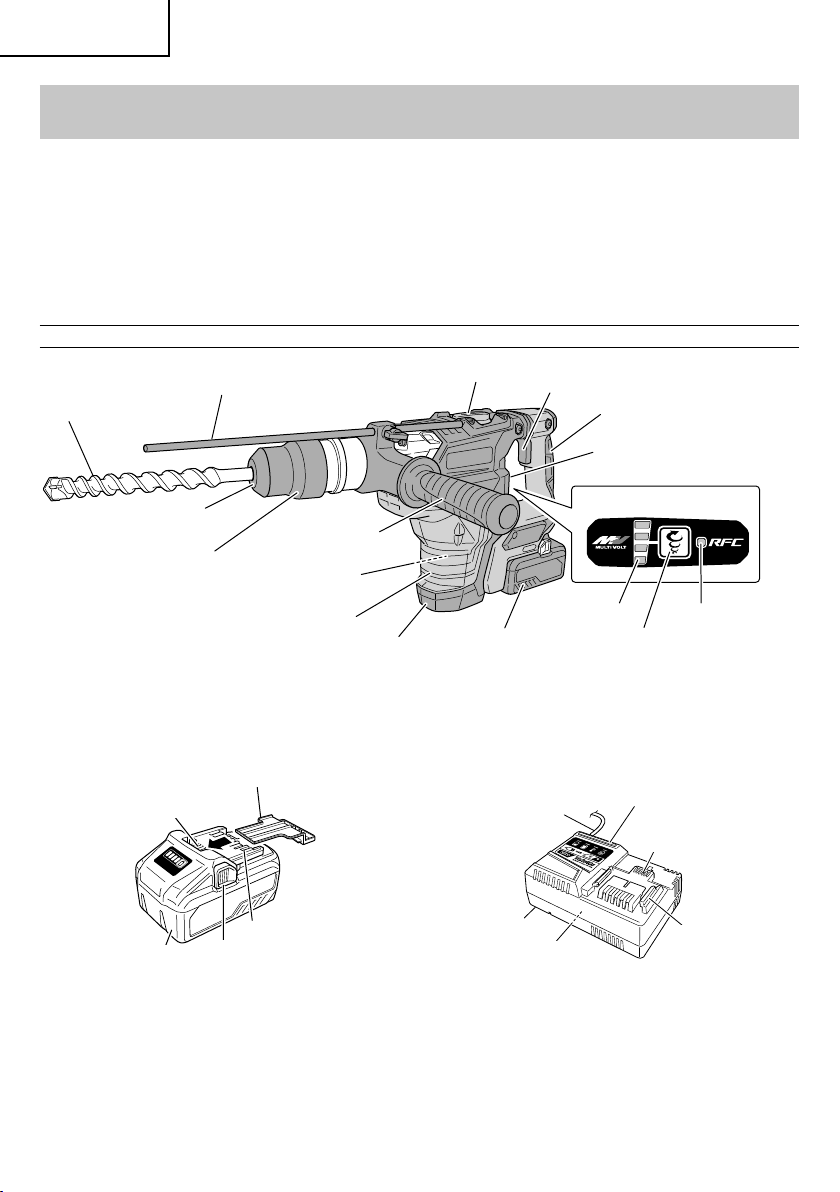
NAME OF PARTS
Stopper
Drill bit
Front cap
Grip
2. Battery 3. Battery Charger
Battery cover
Ventilation holes
Terminals
Battery
Latch
Side handle
Motor
Housing
Tail cover
Selector lever
Battery
Fig. 2
Switch trigger
Display lamp
Rotation speed selector switch
Cord
Body
Nameplate
Handle
Nameplate
RFC indicator lamp
Charge
indicator lamp
Ventilation
holes
Guide rail
<BSL36B18>
Fig. 3
8
<UC18YSL3>
Fig. 4
Page 9

SPECIFICATIONS
1. Cordless Rotar y Hammer
Model DH36DMA
Motor DC motor
Capacity Drill Bit: 1-9/16" (40 mm)
Core Bit: 4-1/8" (105 mm)
No-Load Speed 260 – 590 /min
Full-load Blow 1,420 – 2,860 /min
Model BSL36B18
Battery*
Type Li-ion batter y
Voltage DC 36 V / 18 V
Weight 17.4 lbs (7.9 kg) (BSL36B18 attached)
* Existing batteries (BSL3660/3626/3620, BSL18xx and BSL14xx series, etc.) cannot be used with this tool.
2. Battery Charger
Model UC18YSL3
Input power source Single phase: AC 120 V 60 Hz
Charging time
(At a temperature of 68°F (20°C))
BSL36B18 : Approx. 52 min
Charging voltage DC 14.4 – 18 V
Charging current DC 8.0 A
Weight 1.3 lbs. (0.6 kg)
English
9
Page 10
English
ASSEMBLY AND OPERATION
APPLICATIONS
Rotation and hammering function
○
Drilling anchor holes
○
Drilling holes in concrete
Hammering function only
○
Crushing concrete, chipping, digging, and squaring
(Some applications need optional accessories)
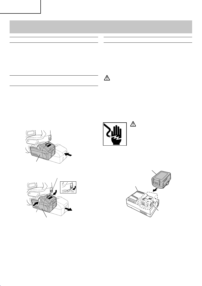
REMOVAL AND INSTALLATION METHOD
OF BATTERY
How to install the battery.
○
Align the battery with the groove in tool handle and
slip it into place.
Always insert it all the way until it locks in place with a
little click, If not, it may accidentally fall out of the tool,
causing injury to you or someone around you (Fig. 5).
○
How to remove the battery.
Lower the stopper lever to detach the lock. Press the
latches on both sides and slide out the battery (Fig. 6).
Battery
Fig. 5
Stopper lever
Insert
CHARGING METHOD
NOTE
Before plugging into the receptacle, make sure the
following points.
○
The power source voltage is stated on the nameplate.
○
The cord is not damaged.
WARNING
Do not charge at voltage higher than indicated
on the nameplate.
If charged at voltage higher than indicated on the
nameplate, the charger will burn up.
1. Connect the charger’s power cord to a receptacle.
When the power cord is connected, the charger’s pilot
lamp will blink in red. (At 1-second intervals)
WARNING
Do not use the electrical cord
if damaged. Have it repaired
immediately.
2. Insert the battery to the battery charger.
Insert the battery into the battery charger as shown in
Fig. 7.
Battery
Charge
indicator lamp
Push
Latch
Battery
Fig. 6
10
Pull out
3. Charging
When inserting a battery in the charger, the charge
indicator lamp will blink in blue.
When the battery becomes fully recharged, the
charge indicator lamp will light up in green. (See
Table 2)
(1) Charge indicator lamp indication
The indications of the charge indicator lamp will be
as shown in Table 2, according to the condition of the
battery charger or the battery.
Guide rail
Fig. 7
Page 11
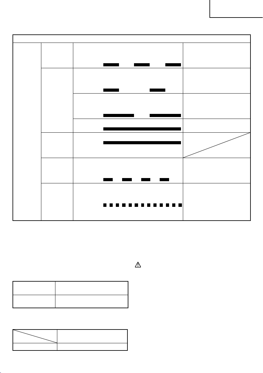
Before
charging
Table 2
Indications of the charge indicator lamp
Lights for 0.5 seconds. Does not light
Blinks
(RED)
for 0.5 seconds.
(off for 0.5 seconds)
English
Plugged into power source
Lights for 0.5 seconds. Does not light
Charge
indicator
lamp
(RED /
BLUE /
GREEN /
PURPLE)
While
charging
Charging
complete
Blinks
(BLUE)
Blinks
(BLUE)
Lights
(BLUE)
Lights
(GREEN)
for 1 second.
(off for 1 second)
Lights for 1 second. Does not light for
0.5 seconds.
(off for 0.5 seconds)
Lights continuously Battery capacity at more than
Lights continuously
(Continuous buzzer sound: about 6
seconds)
Lights for 0.3 seconds. Does not light
Overheat
standby
Blinks
(RED)
for 0.3 seconds.
(off for 0.3 seconds)
Lights for 0.1 seconds. Does not light
for 0.1 seconds.
Charging
impossible
Flickers
(PURPLE)
(off for 0.1 seconds)
(Intermittent buzzer sound: about 2
seconds)
(2) Regarding the temperature of the rechargeable
battery.
The temperatures for rechargeable batteries are
as shown in the Table 3, and batteries that have
become hot should be cooled for a while before being
recharged.
Table 3
Rechargeable
batteries
BSL36B18
Temperatures at which the battery
can be recharged
32°F – 122°F
(0°C – 50°C)
(3) Regarding recharging time (At 68°F (20°C))
Table 4 Charging time
Battery
Charger
UC18YSL3
BSL36B18 Approx. 52 min.
Battery capacity at less than
50%
Battery capacity at less than
80%
80%
Battery overheated. Unable
to charge. (Charging will
commence when battery cools)
Malfunction in the battery or the
charger
NOTE
The recharging time may vary according to the
ambient temperature.
4. Disconnect battery charger from the receptacle.
CAUTION
Do not pull the plug out of the receptacle by
pulling on the cord.
Make sure to grasp the plug when removing from
receptacle to avoid damaging cord.
5. Remove the battery from the battery charger.
Supporting the battery charger with hand, pull out the
battery from the battery charger.
NOTE
Be sure to pull out the battery from the battery charger
after use, and then keep it.
11
Page 12
English
Regarding electric discharge in case of new
batteries, etc.
As the internal chemical substance of new batteries
and batteries that have not been used for an extended
period is not activated, the electric discharge might
be low when using them the fi rst and second time.
This is a temporary phenomenon, and normal time
required for recharging will be restored by recharging
the batteries 2 – 3 times.
How to make the batteries perform longer
(1) Recharge the batteries before they become
completely exhausted.
When you feel that the power of the tool becomes
weaker, stop using the tool and recharge its battery.
If you continue to use the tool and exhaust the electric
current, the battery may be damaged and its life will
become shorter.
(2) Avoid recharging at high temperatures.
A rechargeable battery will be hot immediately after
use. If such a battery is recharged immediately after
use, its internal chemical substance will deteriorate,
and the battery life will be shortened. Leave the
battery and recharge it after it has cooled for a while.
CAUTION
When the battery charger has been continuosly
●
used, the battery charger will be heated, thus
constituting the cause of the failures. Once the
charging has been completed, give 15 minutes
rest until the next charging.
●
If the battery is charged while it is heated because
it has been left for a long time in a location
subject to direct sunlight or because the battery
has just been used, the charge indicator lamp of
UC18YSL3 charger lights for 0.3 seconds, does
not light for 0.3 seconds (off for 0.3 seconds). In
such a case, fi rst let the battery cool, then start
charging.
●
When the pilot lamp or charge indicator lamp
fl ickers (at 0.2–second intervals), check for and
take out any foreign objects in the charger’s
battery installation hole. If there are no foreign
objects, it is probable that the battery or charger
is malfunctioning. Take it to your authorized
Service Center.
HOW TO RECHARGE USB DEVICE
When an unexpected problem occurs, the data in a USB
device connected to this product may be corrupted or lost.
Always make sure to back up any data contained in the
USB device prior to use with this product.
Please be aware that our company accepts absolutely no
responsibility for any data stored in a USB device that is
corrupted or lost, nor for any damage that may occur to a
connected device.
WARNING
○
Prior to use, check the connecting USB cable for
any defect or damage.
Using a defective or damaged USB cable can
cause smoke emission or ignition.
○
When the product is not being used, cover the
USB port with the rubber cover.
Buildup of dust etc. in the USB port can cause
smoke emission or ignition.
NOTE
○
The time required for charging will be longer when
a USB device and battery are being simultaneously
charged.
○
There may be an occasional pause during USB
recharging.
○
When a USB device is not being charged, turn the
USB power switch OFF and remove the USB device
from the charger.
Failure to do so may not only reduce the battery life
of a USB device, but may also result in unexpected
accidents.
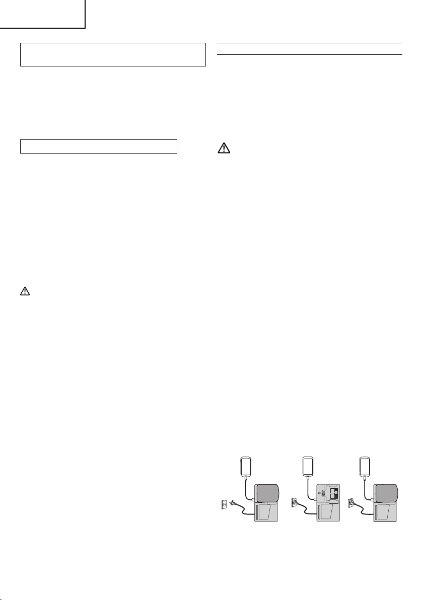
(1) Select a charging method
Depending on the charge method selected, either the
battery is inserted into the charger or the power cord
is plugged into an outlet.
○
Charging a USB device by battery (Fig. 8-a)
○
Charging a USB device from a electrical outlet
(Fig. 8-b)
○
Charging a USB device and battery from a
electrical outlet (Fig. 8-c)
abc
Fig. 8
12
Page 13
English
(2) Turn the USB power switch ON (Fig. 9)
When you turn the USB power switch ON, the USB
power indicator lamp will light up.
Rubber cover
USB power
switch
USB cable
USB port
USB power
indicator lamp
Fig. 9
(3) Connect the USB cable. (Fig. 9)
Pull back the rubber cover and fi rmly plug in a
commercially available USB cable (appropriate to the
device being charged) into the USB port.
○
When the power cord is not plugged into an outlet and
the battery runs out of power, power output will stop
and the USB power indicator lamp will shut off .
○
When the USB power indicator lamp goes out, change
the battery or plug the power cord into an electrical
outlet.
(4) When charging is completed
○
The USB power indicator lamp will not go out when a
USB device has been completely charged.
To verify charge status, check the USB device.
○
Turn the USB power switch OFF and unplug the power
cord from the electrical outlet. (Fig. 9)
○
Remove the battery from the charger and place the
rubber cover over the USB port.
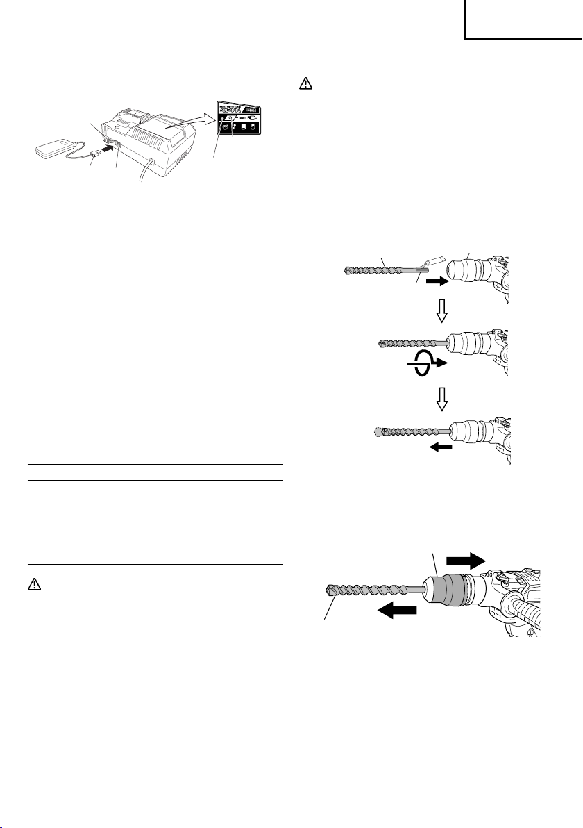
3. How to install tool
CAUTION
For tools such as a drill bit and a bull point, use
only metabo HPT genuine parts.
(1) Clean, then smear the tool shank with the grease
provided in the green tube.
(2) To attach the tool (SDS max shank), insert it into the
hole until it contacts the innermost end of the hole as
illustrated in Fig. 10.
Turn the tool while gently pressing it in, and the groove
of the tool will catch, allowing the tool to enter more
deeply until it is inserted all the way.
Tool
Grip
Tool shank
BEFORE USE
Check the work area to make sure that it is clear of debris
and clutter.
Clear the area of unnecessary personnel. Ensure that
lighting and ventilation is adequate.
PRIOR TO OPERATION
CAUTION
To prevent accidents, make sure to turn the
●
switch off and disconnect the battery when the
drill bits and other various parts are installed
or removed. The power switch should also be
turned off during a work break and after work.
1. Power switch
Ensure that the power switch is in the OFF position.
If the battery is inserted while the power switch is in
the ON position, the power tool will start operating
immediately, which could cause a serious accident.
2. Confi rming condition of the environment:
Confi rm that the work site is placed under appropriate
conditions conforming to prescribed precautions.
Fig. 10
(3) Pull the tool to make sure it is locked completely.
(4) To remove the tool, fully pull the grip in the direction of
the arrow and pull out the tool (Fig. 11).
Pull the grip back
1
Pull the tool out
2
Fig. 11
4. Regulating the number of rotations and hammering
(Fig. 12)
This Rotary Hammer is equipped with a built-in
electronic control circuit that can adjust and regulate
the number of rotations and times of hammering.
This Rotary Hammer can be used by adjusting the
rotation speed selector switch, depending upon
the contents of operation, such as boring holes into
fragile materials, chipping, centering, etc.
13
Page 14

English
Rotation speed
selector switch
Display lamp
Fig. 12
Pressing the rotation speed selector switch switches
rotation speeds as shown in Table 4.
Table 4
Display lamp
sequence
Full-load
speed
Impacts per
Minute
260 340 410 590
1,420 1,850 2,240 2,860
NOTE
○
Rotation speed cannot be adjusted until a battery is
installed to the power tool and the switch has been
triggered once.
○
The rotation speed cannot be changed by pressing
the rotation speed selector switch while the motor is
rotating. To change speeds, switch off the tool fi rst.
5. About the protection function
This product features functions that are designed to
protect the tool itself as well as the battery. While the
switch is pulled, if any of the safeguard functions are
triggered during operation, the display lamp will blink
as described in Table 5. When any of the safeguard
functions are triggered, immediately remove your
fi nger from the switch and follow the instructions
described under corrective action.
Table 5
Display
lamp
Cause Solution
fl ashing
Internal temperature
has risen beyond
Flash
the unit’s specifi ed
temperature.
(Temperature
increase protection
function)
Turn off the unit
and allow it to cool
down for about 15
minutes. When the
temperature goes
down, the unit is
ready for use.
Flash
Excessive pressure
applied to the tool
has resulted in an
Remove the cause of
the overburdening.
overload.
(Overload
protection function)
Flash
Sensor signal read
error.
Repair may be
required.
(Control monitoring
function)
NOTE
Repair may be required if the display lamp continues
to fl ash after taking all necessary steps to correct the
problem. If the problem persists, please arrange for
repairs.
HOW TO USE
CAUTION
To prevent accidents, make sure to turn the
switch off and disconnect the battery when the
drill bits and other various parts are installed
or removed. The power switch should also be
turned off during a work break and after work.
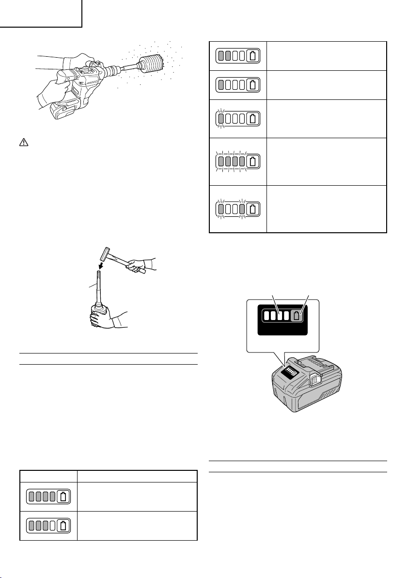
1. How to drill holes (Fig. 13)
(1) Pull the switch trigger after applying the drill bit tip to
the drilling position.
(2) It is unnecessary to forcibly press the Rotary Hammer
main body. It is suffi cient to slightly press the rotary
hammer to an extent that clips are freely discharged.
Fig. 13
CAUTION
Although this machine is equipped with a slip
clutch, if the drill bit becomes bound in concrete
or other material, the resultant stoppage of the
drill bit could cause the machine body to turn in
reaction. Ensure that the main handle and side
handle are gripped fi rmly during operation.
2. How to chisel or demolish (Fig. 14)
By applying the tool tip to the chiseling or demolishing
position, operate the rotary hammer by utilizing its own
14
weight. Forcible pressing or thrusting is unnecessary.
Page 15

Selector lever
English
Fig. 14
3. When drilling at “rotation + hammering”
CAUTION
If you switch the selector lever during motor
rotation, the tool can start to rotate abruptly,
resulting in unexpected accidents. Be sure to
switch the selector lever when the motor is at a
complete stop.
(1) Switching to “rotation + hammering”
(a) Turn the selector lever.
(b) Align ▲ of the selector lever and
of the crank
cover as illustrated in Fig. 15.
Selector lever
Fig. 15
NOTE
Turn the selector lever to check if it is completely
locked and make sure that it does not turn.
NOTE
Fig. 16
Turn the selector lever to check if it is completely
locked and make sure that it does not turn.
(2) When fi xing working positions of tools such as cold
chisel, etc.,
(a) Turn the selector lever.
Align ▲ of the selector lever and
of the crank
cover as illustrated in Fig. 17.
Selector lever
Fig. 17
(b) Turn the Grip or the Tool as illustrated in Fig. 18
and fi x the tool to the desired working direction.
Tool
Grip
4. When crushing and chipping at “hammering”:
CAUTION
If the selector lever is switched during motor
○
rotation, the tool can start to rotate abruptly,
resulting in unexpected accidents. Make sure to
switch the selector lever when the motor is at a
complete stop.
○
If the bull point or cold chisel is used at the
position of “rotation + hammering”, the tool can
start to rotate, resulting in unexpected accidents.
Make sure that they are used at the positon of
“hammering”.
(1) Switching to “hammering”
(a) Turn the selector lever.
(b) Align ▲ of the selector lever and
of the crank
cover as illustrated in Fig. 16.
Fig. 18
(c) Switch the selector lever to “hammering”
according to the procedures mentioned in the
above item (1) and secure the position of the tool.
5. Install the stopper (Fig. 19)
(1) Loosen the wing bolt, and insert the stopper into the
mounting hole on the side handle.
(2) Adjust the stopper position according to the depth of
the hole and tighten the wing bolt securely.
15
Page 16

English
Stopper
Fig. 19
6. Warming up (Fig. 20)
The grease lubrication system in this unit may require
warming up in cold regions.
Position the end of the bit so makes contact with the
concrete, turn on the switch and perform the warming
up operation. Make sure that a hitting sound is
produced and then use the unit.
Fig. 20
CAUTION
When the warming up operation is performed,
hold the side handle and the main body securely
with both hands to maintain a secure grip and be
careful not to twist your body by the jammed drill
bit.
7. How to use the drill bit (taper shank) and the taper
shank adaptor.
(1) Install drill bit with taper shank in the taper shank
adaptor. (Fig. 21)
Taper shank adaptor
Drill bit
(Taper shank)
Mounting hole
Wing bolt
(2) Turn the power on and drill a base hole.
(3) After cleaning out dust with a syringe, attach the plug
to the anchor tip and drive in the anchor with a manual
hammer.
(4) To remove the drill bit with taper shank, insert a
cotter into the slot of the taper shank adaptor, place
supports under the Rotary Hammer and tap the cotter
with a manual hammer. (Fig. 22)
Taper shank
Cotter
USING DRILL CHUCK, CHUCK ADAPTOR
Note that this machine can be used at “rotation only”
if separately sold parts such as drill chuck and chuck
adaptor are attached. Use it with the selector lever
positioned at “rotation + hammering”.
adaptor
Support
Fig. 22
WARNING
During operation, be sure to grip the handle and
the side handle fi rmly to prevent your body from
swaying.
CAUTION
To prevent accidents, make sure to turn the
switch off and pull out the battery.
(1) Switching to “rotation + hammering”
For switching to “rotation + hammering”, follow the
same procedures mentioned in [3. When drilling at
“rotation + hammering”] in Page 15
(2) Attaching chuck adaptor to drill chuck (Fig. 23)
(a) Attach the chuck adaptor to the drill chuck.
(b) The SDS max shank of the chuck adaptor is
equivalent to the drill bit. Therefore, follow the
same procedure as [3. How to install tool] in Page
13 for attaching and detaching.
Drill chuck
SDS max shank
Chuck
adaptor
Fig. 21
16
Fig. 23
Grip
Page 17

English
(3) Drilling
(a) Even if you apply more-than-required pressure to
the machine body, drilling can never be performed
as quickly as you expect. Applying more force
or pressure to the machine body than what is
needed, on the contrary, damages the drill tip,
resulting in the declined working effi ciency and
shortened life of this machine.
(b) A drill can snap sometimes when drilling is almost
fi nished. It is important to relax your thrusting
pressure when drilling is nearing the end.
HOW TO USE THE CORE BIT
When boring penetrating large hole use the core bit. At
that time use with the center pin and the core bit shank
provided as optional accessories.
1. Mounting
CAUTION
To prevent accidents, make sure to turn the
switch off and pull out the battery.
(1) Mount the core bit to the core bit shank. (Fig. 24)
Lubricate the thread of the core bit shank to facilitate
disassembly.
Core bit
(2) Mount the core bit shank to the Rotary Hammer.
(Fig. 25)
Fig. 25
(3) Insert the center pin into the guide plate until it stops.
(4) Engage the guide plate with the core bit, and turn the
guide plate to left or right so that it does not fall even if
it faces downward. (Fig. 26)
Center pin
Guide plate
Core bit shank
Fig. 24
Core bit
Core bit tip
Fig. 26
2. How to bore (Fig. 27)
(1) Install the battery.
(2) A spring is installed in the center pin. Push it lightly
to the wall or the fl oor straight. Connect all over the
surface of the core bit tip and start operating.
(3) When boring about 3/16" (5 mm) in depth the position
of the hole will establish. Bore after that removing the
center pin and the guide plate from core bit.
(4) Application of excessive force will not only expedite
the work, but will deteriorate the tip edge of the drill bit,
resulting in reduced service life of the rotary hammer.
17
Page 18
English
Fig. 27
CAUTION
When removing the center pin and the guide
plate, turn OFF the switch and pull out the
battery.
3. Dismounting (Fig. 28)
Remove the core bit shank from the rotary hammer
and strike the head of the core bit shank strongly two
or three times with a manual hammer holding the core
bit, then the thread becomes loose and the core bit
can be removed.
Lights ;
The battery remaining power is
25% – 50%.
Lights ;
The battery remaining power is less
than 25%
Blinks ;
The battery remaining power is
nearly empty. Recharge the battery
soonest possible
Blinks ;
Output suspended due to high
temperature. Remove the battery
from the tool and allow it to fully cool
down.
Blinks ;
Output suspended due to failure or
malfunction. The problem may be
the battery so please contact your
dealer.
As the remaining battery indicator shows somewhat
diff erently depending on ambient temperature and battery
characteristics, read it as a reference.
Core bit
shank
Fig. 28
ABOUT REMAINING BATTERY INDICATOR
You can check the battery’s remaining capacity by
pressing the remaining battery indicator switch to light the
indicator lamp. (Fig. 29, Table 6)
The indicator will shut off approximately 3 seconds after
the remaining battery indicator switch is pressed.
It is best to use the remaining battery indicator as a
guide since there are slight diff erences such as ambient
temperature and the condition of the battery.
Also, the remaining battery indicator may vary from those
equipped to a tool or charger.
Table 6
State of lamp Battery Remaining Power
Lights ;
The battery remaining power is
over 75%
Lights ;
The battery remaining power is
50% – 75%.
18
Remaining battery
indicator lamp
Remaining battery
indicator switch
Display panel
Fig. 29
NOTE
Do not give a strong shock to the display panel or
break it. It may lead to a trouble.
REACTIVE FORCE CONTROL
This product is equipped with a Reactive Force Control
(RFC) feature that reduces jerking of the tool body.
If the tool bit is suddenly overburdened, any jerking of the
tool body is reduced by activation of the slip clutch or by
stopping of the motor by the sensor built into the tool body.
If the motor is stopped because of overburdening detection
by the controller, the RFC indicator lamp will blink while the
switch is pulled.
Page 19
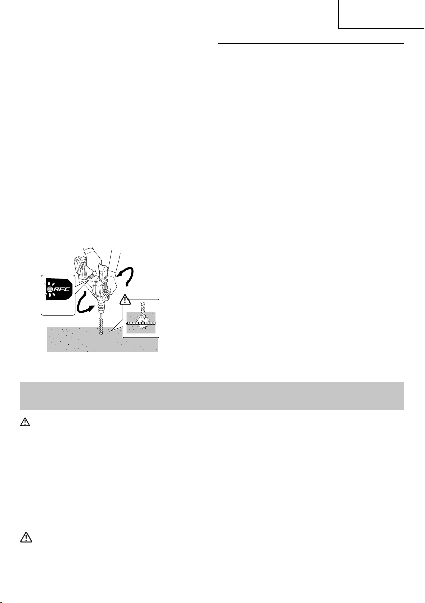
English
In additio n, the lamp will contin ue blinking for appr oximately
three seconds after the switch is released.
The motor will remain stopped while the lamp is blinking.
(Fig. 30)
Because the RFC feature may not activate or its
performance may be insuffi cient depending on the
working environment and conditions, be careful not to
suddenly overburden the tool bit while operating.
●
Possible causes of sudden overburdening
1
Tool bit biting into material
2
Impact against nails, metal or other hard objects
3
Tasks involving prying or any excess application of
pressure, etc.
Also, other causes include any combination of the
aforementioned.
●
When the reactive force control (RFC) is triggered
When the RFC is triggered and the motor stops, turn
off the tool’s switch and remove the cause of the
overburdening before continuing operation.
Arms are twisted
OPERATIONAL CAUTIONS
Resting the unit after continuous work
(1) The power tool is equipped with a temperature
protection circuit to protect the motor.
Continuous work may cause the temperature of the
unit to rise, activating the temperature protection
circuit and automatically stopping operation.
If this happens, allow the power tool to cool before
resuming use.
(2) After use for continuous work, rest the unit for 15
minutes or so when replacing the battery. The
temperature of the motor, switch, etc., will rise if
the work is started again immediately after battery
replacement, eventually resulting in burnout.
Fig. 30
MAINTENANCE AND INSPECTION
CAUTION:
1. Inspecting the tool bits
Since use of a dull tool will cause motor malfunctioning
and degraded effi ciency, replace the tool bit with a
new one or resharpening without delay when abrasion
is noted.
2. Inspecting the screws
Regularly inspect all screws and ensure that they
are properly tightened. Should any of the screws be
loose, retighten them immediately.
WARNING
Using this Rotary Hammer with loosen screws is
extremely dangerous.
Pull out battery before doing any inspection or maintenance.
3. Maintenance of the motor
The motor unit is the very “heart” of the power tool.
Exercise due care to ensure the motor does not
become damaged and/or wet with oil or water.
4. Grease replacement
This Rotary Hammer is of full air-tight construction to
protect against dust and to prevent lubricant leakage.
Therefore, this Rotary Hammer can be used without
lubrication for long periods. Replace the grease as
described below.
○
Grease Replacement Period
After purchase, replace grease after every 6 months
of usage. Ask for grease replacement at the nearest
authorized Service Center.
19
Page 20

English
5. Check for Dust
Dust may be removed with a soft cloth or a cloth
dampened with soapy water.
Do not use bleach, chlorine, gasoline or thinner, for
they may damage the plastics.
6. Inspection of terminals (tool and battery)
Check to make sure that swarf and dust have not
collected on the terminals.
On occasion check prior, during and after operation.
CAUTION
Remove any swarf or dust which may have
collected on the terminals.
Failure to do so may result in malfunction.
7. Disposal of the exhausted battery
WARNING
Do not dispose of the exhausted battery. The
battery must explode if it is incinerated. The
product that you have purchased contains a
rechargeable battery. The battery is recyclable.
At the end of it’s useful life, under various state
and local laws, it may be illegal to dispose of this
battery into the municipal waste stream. Check
with your local solid waste offi cials for details
in your area for recycling options or proper
disposal.
8. Storage
Storing in a place below 104°F (40°C) and out of the
reach of children.
NOTE
Storing lithium-ion batteries
Make sure the lithium-ion batteries have been fully
charged before storing them.
Prolonged storage (3 months or more) of batteries with
a low charge may result in performance deterioration,
signifi cantly reducing battery usage time or rendering
the batteries incapable of holding a charge.
However, signifi cantly reduced battery usage time
may be recovered by repeatedly charging and using
the batteries two to fi ve times.
If the battery usage time is extremely short despite
repeated charging and use, consider the batteries
dead and purchase new batteries.
9. Service and repairs
All quality power tools will eventually require servicing
or replacement of parts because of wear from normal
use. To assure that only authorized replacement parts
will be used, all service and repairs must be performed
by a metabo HPT AUTHORIZED SERVICE CENTER,
ONLY.
Important notice on the batteries for the
metabo HPT cordless power tools
Please always use one of our designated genuine
batteries. We cannot guarantee the safety and
performance of our cordless power tool when used
with batteries other than these designated by us, or
when the battery is disassembled and modifi ed (such
as disassembly and replacement of cells or other
internal parts).
20
Page 21

English
TROUBLESHOOTING GUIDE
WARNING
●
To avoid injury from an accidental start, turn the switch OFF and remove the plug from the power source
or remove the battery from the main body before making any adjustments.
●
All electrical or mechanical repairs should be done only by qualifi ed service technicians. Contact
metabo HPT Authorized Service Center.
1. Power tool
Symptom Possible cause Remedy
Tool doesn’t run No remaining battery power Charge the battery.
Battery isn’t securely attached. Push in the battery until a click is heard.
Concrete dust has accumulated on
the terminals of the battery installation
compartment as well as on the battery
sliding grooves.
The battery was attached while the switch
trigger was ON.
Tool suddenly stopped Tool was overburdened Remove the cause of the overburdening.
Reactive force control was activated
Battery or tool overheated Allow the tool and battery to thoroughly
Tool bits
-can’t be attached
-fall off
Holes can’t be smoothly
drilled.
The shape of the attachment portion
doesn’t match
The drill is worn Replace with a new drill.
Clean off the accumulated concrete dust
with a dry cloth.
Attach the battery when the switch trigger
is OFF.
See “Reactive force control”.
cool.
For the SDS-max shank type, use a bit with
a diameter that is within the designated
range.
Battery cannot be
installed
2. Charger
Symptom Possible cause Remedy
The charge indicator lamp
is rapidly fl ickers purple,
and battery charging
doesn’t begin.
The charge indicator lamp
blinks red, and battery
charging doesn’t begin.
Battery usage time is
short even though the
battery is fully charged.
Attempting to install a battery other than
that specifi ed for the tool.
The battery is not inserted all the way. Insert the battery fi rmly.
There is foreign matter in the battery
terminal or where the battery is attached.
The battery is not inserted all the way. Insert the battery fi rmly.
The battery is overheated. If left alone, the battery will automatically
The battery’s life is depleted. Replace the battery with a new one.
Please install a multi volt type battery.
Remove the foreign matter.
begin charging if its temperature decreases,
but this may reduce battery life. It is
recommended that the battery be cooled in
a well-ventilated location away from direct
sunlight before charging it.
21
Page 22

English
Symptom Possible cause Remedy
The battery takes a long
time to charge.
The USB power lamp
has switched off and the
USB device has stopped
charging.
USB power lamp does not
switch off even though the
USB device has fi nished
charging.
It is unclear what the
charging status of a USB
device is, or whether its
charging is complete.
Charging of a USB device
pauses midway.
Charging of the USB
device pauses midway
when the battery and the
USB device are being
charged at the same time.
Charging of the USB
device doesn’t start when
the battery and the USB
device are being charged
at the same time.
The temperature of the battery, the
charger, or the surrounding environment is
Charge the battery indoors or in another
warmer environment.
extremely low.
The charger’s vents are blocked, causing
Avoid blocking the vents.
its internal components to overheat.
The cooling fan is not running. Contact a metabo HPT Authorized Service
Center for repairs.
The battery’s capacity has become low. Replace the battery with one that has
capacity remaining.
Plug the charger’s power plug into an
electric socket.
The USB power lamp lights up green to
This is not a malfunction.
indicate that USB charging is possible.
The USB power lamp does not switch off
even when charging is complete.
The charger was plugged into an electrical
socket while the USB device was being
charged using the battery as the power
source.
Examine the USB device that is charging to
confi rm its charging status.
This is not a malfunction.
The charger pauses USB charging for about
5 seconds when it is diff erentiating between
power sources.
A battery was inserted into the charger
while the USB device was being charged
using a power socket as the power source.
The battery has become fully charged. This is not a malfunction.
The charger pauses USB charging for
about 5 seconds while it checks whether
the battery has successfully completed
charging.
The remaining battery capacity is
extremely low.
This is not a malfunction.
When the battery capacity reaches a
certain level, USB charging automatically
begins.
22
Page 23
English
ACCESSORIES
WARNING
ALWAYS use Only authorized metabo HPT replacement parts and accessories. Never use replacement
parts or accessories which are not intended for use with this tool. Contact metabo HPT if you are not sure
whether it is safe to use a particular replacement part or accessory with your tool.
The use of any other attachment or accessory can be dangerous and could cause injury or mechanical
damage.
NOTE
Accessories are subject to change without any obligation on the part of the metabo HPT.
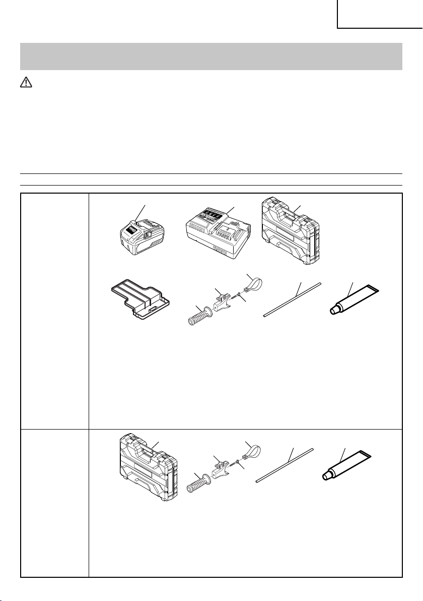
STANDARD ACCESSORIES
DH36DMA
(2WC)
1
4
5
Battery (BSL36B18) .............................................................................. 2
1
2
Battery Charger (UC18YSL3) ................................................................ 1
3
Plastic Case (Code No. 373391) ........................................................... 1
4
Battery cover (Code No. 329897) ......................................................... 2
5
Side Handle (Code No. 330209) ........................................................... 1
6
Mount Ass’y (Code No. 373189) ........................................................... 1
7
Handle Bolt (Code No. 331247) ............................................................ 1
8
Band (Code No. 331246) ....................................................................... 1
9
Stopper (Code No. 971786) ..................................................................1
0
Hammer Grease A (Code No. 981840) ................................................. 1
1
2
2
8
6
7
5
3
4
6
9
3
0
7
DH36DMA
(NNK)
Plastic Case (Code No. 373391) ........................................................... 1
1
2
Side Handle (Code No. 330209) ........................................................... 1
3
Mount Ass’y (Code No. 373189) ........................................................... 1
4
Handle Bolt (Code No. 331247) ............................................................ 1
5
Band (Code No. 331246) ....................................................................... 1
6
Stopper (Code No. 971786) ..................................................................1
7
Hammer Grease A (Code No. 981840) ................................................. 1
23
Page 24

English
OPTIONAL ACCESSORIES.....sold
separately
1. Through-hole drilling (Rotation + Hammering)
(1) Drill bit (SDS-max shank)
External dia. Overall length Code No.
5/8"
(16 mm)
3/4"
(19 mm)
7/8"
(22 mm)
1"
(25 mm)
1-1/8"
(28 mm)
1-1/4”
(32 mm)
1-1/2”
(38 mm)
1-9/16”
(40 mm)
13-3 /8"
(340 mm)
21-1/4"
(540 mm)
13-3 /8"
(340 mm)
21-1/4"
(540 mm)
12-5/8"
(320 mm)
20-15/32"
(520 mm)
12-5/8”
(320 mm)
20-15/32"
(520 mm)
14-9 /16"
(370 mm)
22-7/16"
(570 mm)
14-9 /16"
(370 mm)
22-7/16"
(570 mm)
14-9 /16"
(370 mm)
22-7/16"
(570 mm)
22-7/16"
(570 mm)
313448
313456
313449
313457
313450
313458
313451
313459
313452
313460
313453
313461
313454
313462
313463
2. Anchor hole drilling (Rotation + Hammering)
Adaptor for SDS-plus shank bit
(1) Drill Bit
(SDS-plus shank)
+
(2) Adaptor for SDS-plus
shank bit
(SDS max shank)
Code No. 313465
3. Large-dia. hole boring (Rotation + Hammering)
(Guide plate)
External dia. of
core bit
Code No.
(1) Center pin
Code No.
955165
2" (50 mm) 950475
4-1/8" (105 mm) 955169
(2) Core bit
External dia. Code No.
2" (50 mm) 985380
4-1/8" (105 mm) 955159
(3) Core bit shank
(SDS max shank)
Code No.
313467
Include Guide Plate
4. Drilling holes....For drilling metals and wooden
materials
+
(1) 13mm drill chuck
(13VLD-D)
Code No. 321813
(2) Chuck adaptor
(SDS max shank)
Code No. 313468
(3) Chuck wrench
Code No. 930515
24
Page 25

English
5. Bolt plaching operation with Chemical Anchor
(Rotation + Hammering)
+
(Standard socket
on the market)
Square dimensions of the side
of the socket installation
(1) Chemical Anchor Adaptor
(SDS max shank)
Code No.
1/2" (12.7 mm) 313469
3/4" (19.0 mm) 313470
6. Crushing (Hammering)
(1) Bull point
Overall length Code No.
11" (280 mm) 313471
15-3/4" (400 mm) 313472
7. Groove digging and edging (Hammering)
10. Surface Roughing (Hammering)
+
(1) Bushing Tool
Code No. 313477
(2) Shank
Overall length Code No.
8-21/32" (220 mm) 313479
11. Tamping (Hammering)
+
(1) Rammer
Code No. 313478
(2) Shank
Overall length Code No.
8-21/32" (220 mm) 313479
12. Syringe (for chip removal)
(1) Cold chisel
Overall length Code No.
11" (280 mm) 313473
15-3/4" (400 mm) 313474
8. Asphalt cutting (Hammering)
(1) Cut ter
Overall length Width Code No.
15-3/4" (400 mm) 1-31/32" (50 mm) 313475
9. Digging
(1) Scoop
Code No. 313476
Code No. 320859
13. Hammer grease A
1.1 lbs (500 g) (in a can) Code No. 980927
0.15 lbs (70 g) (in a tube) Code No. 308471
0.07 lbs (30 g) (in a tube) Code No. 981840
14. Battery (BSL36B18)
NOTE
Specifi cations are subject to change without any
obligation on the part of the metabo HPT.
25
Page 26

Français
INFORMATIONS IMPORTANTES DE SÉCURITÉ
Lire et comprendre toutes les précautions de sécurité, les avertissements et les instructions de fonctionnement dans ce
mode d’emploi avant d’utiliser ou d’entretenir cet outil motorisé.
La plupart des accidents causés lors de l’utilisation ou de l’entretien de l’outil motorisé proviennent d’un non respect des
règles ou précautions de base de sécurité. Un accident peut la plupart du temps être évité si l’on reconnaît une situation
de danger potentiel avant qu’elle ne se produise, et en observant les procédures de sécurité appropriées.
Les précautions de base de sécurité sont mises en évidence dans la section “SECURITE” de ce mode d’emploi et dans
les sections qui contiennent les instructions de fonctionnement et d’entretien.
Les dangers qui doivent être évités pour prévenir des blessures corporelles ou un endommagement de la machine sont
identifi és par AVERTISSEMENTS sur l’outil motorisé et dans ce mode d’emploi.
NE JAMAIS utiliser cet outil motorisé d’une manière qui n’est pas spécifi quement recommandée par metabo HPT.
SIGNIFICATION DES MOTS D’AVERTISSEMENT
AVERTISSEMENT indique des situations potentiellement dangereuses qui, si elles sont ignorées, pourraient entraîner
la mort ou de sérieuses blessures.
PRECAUTION indique des situations dangereuses potentilles qui, si elles ne sont pas évitées, peuvent entraîner de
mineures et légères blessures ou endommager la machine.
REMARQUE met en relief des informations essentielles.
SÉCURITÉ
AVERTISSEMENTS DE SÉCURITÉ GÉNÉRAUX CONCERNANT LES OUTILS ÉLECTRIQUES
AVERTISSEMENT
Lire tous les avertissements de sécurité et toutes les instructions
Tout manquement à observer ces avertissements et instructions peut engendrer des chocs électriques, des
incendies et/ou des blessures graves.
Conservez tous les avertissements et toutes les instructions pour vous y référer ultérieurement.
Le terme “outil électrique”, utilisé dans les avertissements, se réfère aux outils électriques (câblé) ou aux outils à
piles (sans fi l).
1) Sécurité de l’aire de travail
a) Maintenir l’aire de travail propre et bien
éclairée.
Les endroits encombrés ou sombres sont
propices aux accidents.
b) Ne pas utiliser d’outils électriques en
présence de liquides, gaz ou poussière
infl ammables, au risque de provoquer une
explosion.
Les outils électriques créent des étincelles
susceptibles d’enfl ammer la poussière.
c) Ne pas laisser les enfants et les visiteurs
s’approcher de vous lorsque vous utiliser un
outil électrique.
Les distractions peuvent faire perdre le contrôle.
2) Sécurité électrique
a) Les prises de l’outil électrique doivent
correspondre à la prise secteur.
26
Ne jamais modifi er la prise.
Ne pas utiliser d’adaptateurs avec les outils
électriques mis à la masse.
Les prises non modifi ées et les prises secteurs
correspondantes réduisent les risques de choc
électrique.
b) Eviter tout contact avec les surfaces mises
à la masse telles que les tuyaux, radiateurs,
bandes et réfrigérateurs.
Le risque de choc électrique est accru en cas de
mise à la masse du corps.
c) Ne pas exposer les outils électriques à la
pluie ou à des conditions humides.
Si l’eau pénètre dans l’outil, cela augmente les
risques de choc électrique.
d) Ne pas utiliser le cordon à tort. Ne jamais
utiliser le cordon pour transporter ou
débrancher l’outil électrique.
Page 27

Français
Maintenir le cordon loin de la chaleur, de
l’huile, des bords pointus ou des pièces
mobiles.
Les cordons endommagés ou usés augmentent
les risques de choc électrique.
e) En cas d’utilisation d’un outil électrique à
l’extérieur, utiliser un cordon de rallonge
adapté à un usage extérieur.
L’utilisation d’un cordon adapté à l’usage extérieur
réduit les risques de choc électrique.
f) Si vous devez utiliser un outil électrique dans
un endroit humide, utilisez une alimentation
protégée contre les courants résiduels.
L’utilisation d’un dispositif de protection contre
les courants résiduels réduit le risque de choc
électrique.
3) Sécurité personnelle
a) Restez alerte, regarder ce que vous faites et
usez de votre bon sens en utilisant un outil
électrique.
Ne pas utiliser d’outil électrique si vous êtes
sous l’infl uence de drogues, d’alcool ou de
médicaments.
Pendant l’utilisation d’outils électrique, un instant
d’inattention peut entraîner des blessures graves.
b) Utiliser un équipement de protection
individuelle. Toujours porter des verres de
protection.
L’utilisation d’équipements de protection tels
que les masques anti-poussière, les chaussures
de sécurité anti-dérapantes, les casques ou
les protections auditives dans des conditions
appropriées réduisent les risques de blessures.
c) Empêcher les démarrages intempestifs.
Veiller à ce que l’interrupteur soit en
position d’arrêt avant de brancher à une
source d’alimentation et/ou une batterie, de
ramasser l’outil au sol ou de le transporter.
Transporter les outils électriques avec le doigt sur
l’interrupteur ou brancher les outils électriques
avec l’interrupteur en position de marche peut
entraîner des accidents.
d) Retirer toute clé de sécurité ou clé avant de
mettre l’outil électrique en marche.
Laisser une clé ou une clé de sécurité sur une
partie mobile de l’outil électrique peut engendrer
des blessures.
e) Ne pas trop se pencher. Toujours garder une
bonne assise et un bon équilibre pendant le
travail.
Cela permet un meilleur contrôle de l’outil
électrique dans des situations imprévisibles.
f) Porter des vêtements adéquats. Ne pas porter
de vêtements amples ni de bijoux. Maintenir
les cheveux, les vêtements et les gants loin
des pièces mobiles.
Les vêtements amples ou les cheveux longs
peuvent se prendre dans les pièces mobiles.
g) En cas de dispositifs destinés au
raccordement d’installations d’extraction et
de recueil de la poussière, veiller à ce qu’ils
soient correctement raccordés et utilisés.
L’utilisation d’un dispositif de collecte de la
poussière peut réduire les dangers associés à la
poussière.
4) Utilisation et entretien d’un outil électrique
a) Ne pas forcer sur l’outil électrique. Utiliser
l’outil électrique adapté à vos travaux.
Le bon outil électrique fera le travail mieux et en
toute sécurité au régime pour lequel il a été conçu.
b) Ne pas utiliser l’outil électrique si
l’interrupteur ne le met pas en position de
marche et d’arrêt.
Tout outil ne pouvant être contrôlé par l’interrupteur
est dangereux et doit être réparé.
c) Débrancher la prise ou retirer la batterie avant
de procéder à des réglages, au remplacement
des accessoires ou au stockage des outils
électriques.
Ces mesures préventives de sécurité réduisent
les risques de démarrage accidentel de l’outil
électrique.
d) Stockez les outils électriques inutilisés hors
de la portée des enfants et ne pas laisser des
personnes non familiarisées avec l’outil ou
ces instructions utiliser l’outil électrique.
Les outils électriques sont dangereux entre les
mains d’utilisateurs non habilités.
e) Entretenir les outils électriques. Vérifi er
l’absence de mauvais alignement ou d’arrêt,
d’endommagement de pièces ou toute autre
condition susceptible d’aff ecter l’opération
de l’outil.
Si l’outil est endommagé, le faire réparer
avant utilisation.
De nombreux accidents sont dus à des outils mal
entretenus.
f) Maintenir les outils coupants aiguisés et
propres.
Des outils coupants bien entretenus avec des
bords aiguisés sont moins susceptibles de se
coincer et plus simples à contrôler.
g) Utiliser l’outil électrique, les accessoires et
les mèches de l’outil, etc. conformément à ces
instructions en tenant compte des conditions
d’utilisation et du travail à réaliser.
L’utilisation de l’outil électrique pour des
opérations diff érentes de celles pour lesquelles il
a été conçu est dangereuse.
5) Utilisation et entretien de la batterie
a) Recharger la batterie uniquement avec le
chargeur recommandé par le fabricant.
27
Page 28

Français
Un chargeur inadéquat pour le type de batterie
peut entraîner un risque d’incendie en cas
d’utilisation avec une autre batterie.
b) Utiliser les outils électriques uniquement
avec les batteries spécifi ées.
L’utilisation d’autres batteries peut entraîner un
risque de blessures et d’incendie.
c) Lorsque la batterie est inutilisée, la garder
à l’écart d’objets métalliques comme des
trombones, des pièces de monnaie, des clés,
des clous, des vis ou autres petits objets
métalliques pouvant raccorder les bornes.
La connexion des bornes peut entraîner des
blessures ou un incendie.
d) En cas d’utilisation dans des conditions
extrêmes, du liquide peut être émis de la
batterie. Éviter tout contact. en cas de contact
accidentel, rincer à l’eau. Si le liquide entre en
contact avec les yeux, consulter un médecin.
Le liquide émis par la batterie peut entraîner des
irritations et des brûlures.
6) Service
a) Faire entretenir l’outil électrique par un
technicien habilité à l’aide de pièces de
rechange identiques exclusivement.
Cela garantira le maintien de la sécurité de l’outil
électrique.
– AVERTISSEMENT –
Pour réduire tout risque de blessure, l’utilisateur
doit lire le mode d’emploi.
AVERTISSEMENT:
La poussière résultant d'un ponçage, d'un sciage,
d'un meulage, d'un perçage ou de toute autre activité
de construction renferme des produits chimiques
qui sont connus par l'Etat de Californie pour causer
des cancers, des défauts de naissance et autres
anomalies de reproduction. Nous énumérons cidessus certains de ces produits chimiques:
●
Plomb des peintres à base de plomb,
●
Silice cristalline des briques et du ciment et autres
matériaux de maçonnerie, et
●
Arsenic et chrome du bois d'oeuvre traité
chimiquement.
Le risque d'exposition à ces substances varie en
fonction de la fréquence d'exécution de ce genre
de travail. Pour réduire l'exposition à ces produits
chimiques, travailler dans un lieu bien ventilé, et porter
un équipement de protection agréé, par exemple un
masque anti-poussière spécialement conçu pour fi lter
les particules microscopiques.
REGLES DE SECURITE SPECIFIQUES ET
SYMBOLES
1. Porter des protections anti-bruit.
L’exposition au bruit peut engendrer une
perte de l’audition.
2. Utilisez les poignées auxiliaires, si fourni avec
l’outil.
Toute perte de contrôle peut entraîner des blessures.
3. Maintenez les outils électriques par les surfaces
de prise isolées lorsque vous eff ectuez une
opération au cours de laquelle l’accessoire de
coupe peut entrer en contact avec un câblage
caché.
Le contact d’un outil de coupe avec un fi l “sous
tension” risque de mettre les parties métalliques de
l’outil “sous tension” d’électrocuter l’utilisateur.
4. NE JAMAIS toucher la mèche avec des mains nues
après l’utilisation.
5. NE JAMAIS porter de gants faits d’une matière qui
risque de s’enrouler, comme du coton, de la laine, de
la toile ou de la fi celle, etc.
6. TOUJOURS fi xer la poignée latérale et tenir le
marteau rotatif solidement.
7. NE JAMAIS toucher les parties mobiles.
NE JAMAIS placer ses mains, ses doigts ou toute
autre partie de son corps près des parties mobiles de
l’outil.
8. NE JAMAIS utiliser l’outil sans que tous les
dispositifs de sécurité ne soient en place.
NE JAMAIS faire fonctionner cet outil sans que tous
les dispositifs et caractéristiques de sécurité ne soient
en place et en état de fonctionnement. Si un entretien
ou une réparation nécessite le retrait d’un dispositif ou
d’une caractéristique de sécurité, s’assurer de bien
remettre en place le dispositif ou la caractéristique de
sécurité avant de recommencer à utiliser l’outil.
9. Utiliser l’outil correct
Ne pas forcer sur un petit outil ou accessoire pour
faire le travail d’un outil de grande puissance.
Ne pas utiliser un outil pour un usage pour lequel il n’a
pas été prévu: par exemple, ne pas utiliser une scie
circulaire pour couper des branches d’arbre ou des
bûches.
10. NE JAMAIS utiliser un outil motorisé pour des
applications autres que celles spécifi ées.
NE JAMAIS utiliser un outil motorisé pour des
applications autres que celles spécifi ées dans le
mode d’emploi.
28
Page 29

Français
11. Manipuler l’outil correctement
Utiliser l’outil de la façon indiquée dans ce mode
d’emploi. Ne pas laisser tomber ou lancer l’outil.
NE JAMAIS permettre que l’outil soit utilisé par des
enfants, des personnes non familiarisées avec son
fonctionnement ou un personnel non autorisé.
12. Maintenir toutes les vis, tous les boulons et les
couvercles fermement en place.
Maintenir toutes les vis, tous les boulons et les
couvercles fermement montés. Vérifi er leurs
conditions périodiquement.
13. Ne pas utiliser les outils motorisés si le
revêtement de plastique ou la poignée est fendu.
Des fentes dans le revêtement ou la poignée peuvent
entraîner une électrocution. De tels outils ne doivent
pas être utilisés avant d’être réparé.
14. Les mèches et les accessoires doivent être
fermement montés sur l’outil.
Prévenez les blessures potentielles à vous-même ou
aux autres. Les mèches et les accessoires qui ont été
montés sur l’outil doivent être sécurisés et serrés.
15. Garder propres les évents d’air du moteur.
Les évents d’air du moteur doivent être maintenus
propres de façon que l’air puisse circuler librement
tout le temps. Vérifi er les accumulations de poussière
fréquemment.
16. Comme l’outil sans fi l fonctionne avec l’énergie de la
batterie, soyez conscient du fait qu'il peut commencer
à fonctionner à tout moment.
17. NE JAMAIS utiliser un outil défectueux ou qui
fonctionne anormalement.
Si l’outil n’a pas l’air de fonctionner normalement, fait
des bruits étranges ou sans cela paraît défectueux,
arrêter de l’utiliser immédiatement et le faire réparer
par un centre de service metabo HPT autorisé.
18. NE JAMAIS laisser fonctionner l’outil sans
surveillance. Le mettre hors tension.
Ne pas abandonner l’outil avant qu’il ne soit
complètement arrêté.
19. Manipuler l’outil motorisé avec précaution.
Si un outil motorisé tombe ou frappe un matériau dur
accidentellement, il risque d’être déformé, fendu ou
endommagé.
20. Ne pas essuyer les parties en plastique avec du
solvant.
Les solvants comme l’essence, les diluants, la
benzine, le tétrachlorure de carbone et l’alcool
peuvent endommager et fi ssurer les parties en
plastique. Ne pas les essuyer avec de tels solvants.
Essuyer les parties en plastique avec un chiff on doux
légèrement imbibé d’une solution d’eau savonneuse
et sécher minutieusement.
21. TOUJOURS porter des lunettes de protection qui
22. N’utilisez pas le produit si l’outil ou les bornes de la
batterie (fi xation de la batterie) sont déformés.
Installer la batterie peut entraîner un court-circuit qui
pourrait provoquer des émissions de fumée ou une
ignition.
23. Gardez les bornes de l’outil (fi xation de la batterie)
exemptes de copeaux et de poussière.
○
Avant toute utilisation, assurez-vous qu’aucun
copeau ou poussière ne s’est accumulé sur la zone
des bornes.
○
Pendant l’utilisation, essayez d’éviter que des
copeaux ou de la poussière provenant de l’outil ne
tombent sur la batterie.
○
Lors de la suspension de l’opération ou après
l’utilisation, ne laissez pas l’outil dans un endroit
où il pourrait être exposé à des copeaux ou de la
poussière.
Le non-respect de cette consigne peut entraîner un
court-circuit qui pourrait provoquer des émissions de
fumée ou une ignition.
24. TOUJOURS vérifi er s’il y a des objets encastrés, par
exemple des fi ls électriques. Le fait de toucher avec
l’outil un fi l ou un câble électrique sous tension risque
de provoquer une décharge électrique.
Avant l’utilisation, vérifi er s’il y a des objets dissimulés,
par exemple des câbles électriques, dans le mur, le
plancher ou le plafond.
25. Défi nitions pour les symboles utilisés sur cet
outil
V .............volts
—
---
no ...........vitesse sans charge
---/min .....tours par minute
CONSIGNES DE SÉCURITÉ IMPORTANTES
POUR LE CHARGEUR DE BATTERIE
respectent les dernières révisions du
Standard ANSI Z87.1.
........... cour ant cont inu
AVERTISSEMENT
Une utilisation incorrecte ou dangereuse des
chargeurs de batterie peut entraîner la mort ou
des blessures graves.
LIRE TOUT CE MODE D'EMPLOI
1. Ce manuel renferme des consignes de sécurité et
d’utilisation importantes pour le chargeur de batterie
modèle UC18YSL3.
29
Page 30

Français
2. Avant d’utiliser le chargeur de batterie, lire toutes les
étiquettes d’instruction et de précaution apposées
sur (1) le chargeur de batterie, (2) la batterie, et (3) le
produit utilisant la batterie.
3. Pour réduire tout risque de blessure, NE recharger
QUE les batteries rechargeables metabo HPT de
type BSL36B18 et de série BSL18. Les autres types
de batterie pourraient exploser et provoquer des
blessures ou des dommages.
4. L’utilisation d’un accessoire non recommandé ou non
vendu par le fabricant du chargeur de batterie risque
de provoquer un feu, une décharge électrique ou des
blessures.
5. Pour réduire tout risque de dommage de la fi che et du
cordon électrique, débrancher le cordon du chargeur
en tirant sur la fi che.
CALIBRE MINIMUM RECOMMANDÉ POUR LES CORDONS DE RALLONGE
Intensité nominale d’entrée CA (ampères)* Calibre du cordon
Egal ou
supérieur à
0 2 18 18 18 16
2 3 18 18 16 14
3 4 18 18 16 14
* Si l’intensité nominale d’entrée du chargeur de batterie est donnée en watts et non en ampères, calculer la capacité
en ampères correspondante en divisant la capacité en ampères par la capacité de tension, par exemple:
mais non
inférieur à
DES CHARGEURS DE BATTERIE
1,250 watts
125 volts
6. Vérifi er que le cordon est placé de façon que
personne ne puisse marcher dessus, se prendre les
pieds dedans, ni l’endommager ou le soumettre à des
contraintes.
7. Ne pas utiliser de cordon de rallonge si cela n’est
pas absolument nécessaire. L’utilisation d’un cordon
de rallonge incorrect pourrait entraîner un feu ou une
décharge électrique. Si l’on doit utiliser un cordon de
rallonge, s’assurer que:
a. Les broches de la rallonge ont les mêmes numéro,
taille et forme que celles de la fi che du chargeur ;
b. Le cordon de rallonge est correctement raccordé
et en bon état électrique ;
c. Le calibre du fi l doit être au moins suffi sant pour
l’intensité nominale CA (ampères) du chargeur de
batterie spécifi ées dans le tableau ci-dessous.
Tableau 1
Longueur de cordon en pieds (mètres)
25 (7.5) 50 (15) 100 (30) 150 (45)
= 10 ampères
8. Ne pas utiliser le chargeur si son cordon ou sa fi che
sont endommagés - Le remplacer immédiatement.
9. Ne pas utiliser le chargeur s’il a reçu un coup, s’il
est tombé ou endommagé de toute autre manière.
L’apporter à un réparateur qualifi é.
10. Ne pas démonter le chargeur ni le produit qui reçoit
la batterie ; si un entretien ou des réparations sont
nécessaires, les apporter à un réparateur qualifi é. Un
remontage incorrect pourrait provoquer une décharge
électrique ou un feu.
11. Pour réduire tout risque de décharge électrique,
débrancher le chargeur de la prise secteur avant
tout entretien ou nettoyage. Il ne suffi t pas de sortir la
batterie.
30
CONSIGNES DE SÉCURITÉ
IMPORTANTES POUR L’UTILISATION
DE LA BATTERIE ET DU CHARGEUR DE
BATTERIE
Pour pouvoir utiliser la scie circulaire à batterie, il faudra
recharger la batterie. Avant d’utiliser le chargeur de
batterie modèle UC18YSL3, bien lire attentivement
toutes les consignes et les avertissements signalés sur le
chargeur, sur la batterie ou dans ce manuel.
BIEN NOTER: UTILISER EXCLUSIVEMENT LES
BATTERIES metabo HPT DE TYPE BSL36B18.
LES AUTRES TYPES DE BATTERIE POURRAIENT
EXPLOSER OU PRO VOQUER DES BLESSURES.
Pour éviter tout risque de blessure, observer les consignes
suivantes:
AVERTISSEMENT
Une utilisation incorrecte de la batterie ou du
chargeur de batterie risque de provoquer des
blessures. Pour éviter tout risque de blessure:
Page 31

Français
1. NE JAMAIS démonter la batterie.
2. NE JAMAIS jeter la batterie au feu, même si elle est
endommagée ou complètement usée. La batterie
risque d’exploser au feu.
3. NE JAMAIS court-circuiter la batterie.
4. NE JAMAIS insérer d’objets dans les ouïes d’aération
du chargeur. Il pourrait en résulter un choc électrique
ou des dommages du chargeur.
5. NE JAMAIS eff ectuer la recharge à l’extérieur.
Eloigner la batterie des rayons directs du soleil et
utiliser exclusivement dans des endroits à faible
humidité et bien aérés.
6. NE JAMAIS eff ectuer la recharge si la température
est inférieure à 14°F (-10°C) ou supérieure à 104°F
(40°C).
7. NE JAMAIS raccorder deux chargeurs de batterie
ensemble.
8. NE JAMAIS insérer de corps étrangers dans l’orifi ce
de la batterie ou du chargeur de batterie.
9. NE JAMAIS utiliser de transformateur-élévateur pour
la recharge.
10. NE JAMAIS utiliser l’alimentation CC pour charger.
11. NE JAMAIS ranger la batterie ou le chargeur de
batterie dans un endroit où la température peut
atteindre ou dépasser 104°F (40°C), comme à
l’intérieur d’une boîte métallique ou d’une voiture.
12. NE JAMAIS exposer la batterie ou le chargeur de
batterie à la pluie ou l’humidité.
13. TOUJOURS alimenter le chargeur sur une prise
secteur domestique standard (120 volts). L’utilisation
du chargeur à une autre tension peut entraîner une
surchauff e et endommager le chargeur.
14. TOUJOURS attendre au moins 15 minutes entre deux
recharges pour éviter toute surchauff e du chargeur.
15. TOUJOURS débrancher le cordon d’alimentation de
la prise secteur lorsqu’on ne se sert pas du chargeur.
PRÉCAUTIONS RELATIVES A LA
BATTERIE AU LITHIUM ION
Pour prolonger sa durée de vie, la batterie lithium-ion
est équipée d'une fonction de protection qui coupe
automatiquement l'alimentation.
Dans les cas 1 à 3 décrits ci-dessous, il est possible que
le moteur s'arrête lorsque vous utilisez ce produit, même
si vous actionnez le commutateur. Il ne s'agit pas d'un
dysfonctionnement, mais du fonctionnement normal de la
protection.
1. Lorsque la charge restante de la batterie diminue, le
moteur s'arrête.
Dans ce cas de fi gure, chargez immédiatement la
batterie.
2. En cas de surcharge de l'outil, actionnez le
commutateur de l'outil et éliminez les causes de la
surcharge. Vous pouvez ensuite recommencer à
utiliser l'outil.
3. En cas de surchauff e due à un travail trop intensif,
l’alimentation de la batterie peut se couper.
Dans ce cas, arrêtez toute utilisation de la batterie et
laissez-la refroidir. Vous pouvez ensuite recommencer
à l’utiliser.
En outre, respectez la précaution et l’avertissement
suivants.
AVERTISSEMENT
Afi n d’éviter toute fuite de la batterie, génération
de chaleur, émission de fumée, explosion et
infl ammation, respectez scrupuleusement les
précautions suivantes :
1. Assurez-vous que les copeaux et la poussière ne
s’accumulent pas sur la batterie.
○
Lorsque vous travaillez, assurez-vous que les
copeaux et la poussière ne tombent pas sur la
batterie.
○
Assurez-vous que les copeaux et la poussière
qui tombent sur l’outil lorsque vous travaillez ne
s’accumulent pas sur la batterie.
○
Ne conservez pas une batterie inutilisée dans un
endroit qui est exposé aux copeaux et à la poussière.
○
Avant de stocker une batterie, retirez tous les copeaux
et la poussière qui ont pu y adhérer et ne la conservez
pas avec des pièces métalliques (vis, clous, etc.).
2. Ne percez pas la batterie à l’aide d’un objet pointu tel
qu’un clou. Ne la frappez pas à l’aide d’un marteau.
Ne marchez pas dessus, ne la lancez pas et ne la
soumettez pas un à choc physique important.
3. N’utilisez pas une batterie dont l’extérieur est déformé
ou laisse penser qu’elle est défectueuse.
4. N’insérez pas la batterie à l’envers (pôles inversés).
5. Ne raccordez pas directement la batterie à une prise
électrique ou à un allume-cigare.
6. N’utilisez pas la batterie à d’autres fi ns que celle
spécifi ée.
7. En cas d’échec du chargement d’une batterie, même
après un certain délai, arrêtez immédiatement le
rechargement.
8. N’exposez pas la batterie à des températures ou à
une pression élevées (four à micro-ondes, séchoir,
conteneur sous haute pression).
9. Maintenez à la batterie à l’écart de toute fl amme en
cas de détection d’une fuite ou d’une mauvaise odeur.
10. Ne pas utiliser à proximité d’une source puissante
d’électricité statique.
11. En cas de fuite de la batterie, de mauvaise odeur,
de génération de chaleur, de décoloration, de
déformation ou d’anomalie en cours d’utilisation, de
rechargement ou d’entreposage, ôtez immédiatement
la batterie de l’équipement ou du chargeur de batterie
et ne l’utilisez plus.
31
Page 32

Français
12. Ne plongez jamais la batterie dans de l’eau ou tout
autre liquide, et ne laissez aucun liquide s’infi ltrer
à l’intérieur de la batterie. L’entrée de liquides
conducteurs, tel que de l’eau, peut causer des
dommages pouvant entraîner un incendie ou une
explosion. Rangez votre batterie dans un endroit frais
e t s ec , à l’é ca rt d’o bj et s c om bu st ib le s e t i n fl ammables.
Les atmosphères corrosives doivent être évitées.
PRECAUTION
1. En cas de projection dans les yeux de liquide ayant
fuit de la batterie, ne vous frottez pas les yeux, rincezles à l’eau claire et contactez immédiatement un
médecin.
En l’absence de traitement, le liquide peut détériorer
l’oeil.
2. En cas de projection de liquide ayant fuit de la
batterie sur votre peau ou vos vêtements, rincez
immédiatement ces derniers à l’eau claire (au robinet).
Le liquide peut provoquer une irritation de la peau.
3. En cas de détection de rouille, de mauvaise odeur,
de surchauff e, de décoloration, de déformation et/ou
autres anomalies lors de la première utilisation de la
batterie, n’utilisez pas cette dernière et renvoyez-la au
fournisseur ou au fabricant.
AVERTISSEMENT
Un court-circuit risque de se produire et causer un
incendie, si un corps étranger conducteur d’électricité
passe dans les bornes de la pile au lithium-ion. Veuillez
respecter les consignes suivantes pour le rangement de
la pile.
○
Ne pas mettre d’objet conducteur d’électricité,
tels que clous, fi l d’acier, de cuivre ou autre fi l
dans la mallette de rangement.
○
Soit ranger le bloc de pile avec l’outil électrique
ou de manière sécuritaire en l’enfonçant dans
le couvercle jusqu’à ce que les orifi ces de
ventilation soient dissimulés afi n d’éviter les
courts-circuits. (Voir la Fig. 3)
À PROPOS DU TRANSPORT DE LA
BATTERIE LITHIUM-ION
Lors du transport d’une batterie lithium-ion, veuillez
observer les précautions suivantes.
AVERTISSEMENT
Informez la société de transport qu'un paquet
contient une batterie lithium-ion, informez la société
de sa puissance de sortie et suivez les instructions
de la société de transport lors de l'organisation du
transport.
●
Les batteries lithium-ion qui dépassent une
puissance de sortie de 100 Wh font partie de
la classifi cation de transport des produits
dangereux et nécessitent l'application de
procédures spéciales.
●
Pour un transport vers l'étranger, vous devez
vous conformer aux lois internationales et aux
normes et réglementations en vigueur dans le
pays de destination.
●
Si le BSL36B18 est installé dans l’outil électrique,
la puissance utile dépassera 100 Wh et l’appareil
sera classé comme Produits dangereux pour la
classifi cation fret transporté.
Puissance de sortie
Wh
Nombre de 2 à 3 chiff res
Fig. 1
CONSERVER CES INSTRUCTIONS
ET
LES METTRE A LA DISPOSITION DES AUTRES
UTILISATEURS
ET
PROPRIETAIRES DE CET OUTIL!
32
Page 33

Français
DESCRIPTION FONCTIONNELLE
REMARQUE
Les informations contenues dans ce mode d’emploi sont conçues pour assister l’utilisateur dans une utilisation sans
danger et un entretien de l’outil motorisé.
NE JAMAIS utiliser ni entreprendre une révision de l’outil sans avoir d’abord lu et compris toutes les instructions de
sécurité contenues dans ce manuel.
Certaines illustrations dans ce mode d’emploi peuvent montrer des détails ou des accessoires diff érents de ceux de
l’outil motorisé utilisé.
NOM DES PARTIES
Quenouille
Foret de perçage
Capuchon avant
Attache coulissante
2. Batterie 3. Chargeur de batterie
Couvercle de batterie
Orifi ces de ventilation
Bornes
Batterie
Loquet
Poignée
latérale
Moteur
Carter
Couvercle de queue
Sélecteur
Batterie
Fig. 2
Corps
Interrupteur
Témoin d'affi chage
Sélecteur de vitesse
de rotation
Cordon
Plaque
signalétique
Poignée
Plaque signalétique
Témoin
d'indicateur RFC
Témoin de charge
Orifi ces de ventilation
Rail de guidage
<BSL36B18>
Fig. 3
<UC18YSL3>
Fig. 4
33
Page 34

Français
SPECIFICATIONS
1. Marteau rotatif sans fi l
Modèle DH36DMA
Moteur Moteur CC
Capacité Mèche: 1-9/16" (40 mm)
Vitesse sans charge 260 – 590 /min
Vitesse de percussion à pleine charge 1,420 – 2,860 /min
Modèle BSL36B18
Batterie*
Type Batterie au Li-ion
Tension CC 36 V / 18 V
Poids 17.4 lbs (7.9 kg) (BSL36B18 attaché)
* Les batteries existantes (séries BSL3660/3626/3620, BSL18xx et BSL14xx) ne peuvent pas être utilisées avec cet outil.
2. Chargeur de batterie
Modèle UC18YSL3
Source d’alimentation d’entrée Monophasée: AC 120 V 60 Hz
Durée de recharge
(à une température de 68°F (20°C))
Tension de charge CC 14.4 – 18 V
Charging current CC 8.0 A
Poids 1.3 lbs. (0.6 kg)
Couronne: 4-1/8" (105 mm)
BSL36B18 : Environ 52 min
34
Page 35

ASSEMBLAGE ET FONCTIONNEMENT
Français
APPLICATIONS
Fonction de rotation et de percussion
○
Perçage de trous d’ancrage
○
Perçage de trous dans béton
Fonction de percussion uniquement
○
Broyage du béton, burinage, creusage et équarrissage
(Certaines applications nécessitent des accessoires
en option)
MÉTHODE DE RETRAIT ET
D’INSTALLATION DE LA BATTERIE
Installation de la batterie
○
Aligner la batterie sur la fente de la poignée de l’outil
et la glisser à l’intérieur.
Toujours insérer la batterie à fond, jusqu’à ce qu’elle
se bloque avec un petit déclic. Sinon, elle risque
de tomber accidentel lement de l’outil et de blesser
l’opérateur ou d’autres personnes alentour (Fig. 5).
○
Retrait de la batterie
Abaissez le levier de la quenouille pour débloquer le
verrou. Appuyez sur les loquets de chaque côté et
faites coulisser la batterie (Fig. 6).
Batterie
Fig. 5
Levier de butée
Insérer
MÉTHODE DE RECHARGE
REMARQUE
Avant de brancher le chargeur dans la prise, vérifi er
les points suivants.
○
La tension de la source d’alimentation est indiquée
sur la plaque signalétique.
○
Le cordon n’est pas endommagé.
AVERTISSEMENT
Ne pas eff ectuer de recharge à une tension
supérieure à la tension indiquée sur la plaque
signalétique. Cela brûlerait le chargeur.
1. Brancher le cordon d’alimentation du chargeur sur
une prise secteur.
Quand vous raccordez la fi che du chargeur à une
prise murale, la lampe témoin clignote en rouge. (À
intervalles d’une seconde)
AVERTISSEMENT
Ne pas utiliser le cordon
électrique s’il est endommagé.
Le faire réparer immédiate ment.
2. Insérer la batterie dans le chargeur de batterie.
Insérer la batterie dans le chargeur de batterie comme
indiqué à la Fig. 7.
Batterie
Témoin de
charge
Pousser
Taquet
Batterie
Fig. 6
Tirer
Rail de guidage
Fig. 7
3. Recharge
Lorsque vous insérez une batterie dans le chargeur,
le témoin de charge clignote en bleu.
Lorsque la batterie est complètement chargée, le
témoin de charge s’allume en vert. (Voir Tableau 2)
(1) Indication du témoin de charge
Les indications du témoin de charge sont expliquées
dans le Tableau 2, en fonction de l’état du chargeur de
batterie ou de la batterie.
35
Page 36

Français
Avant la
charge
Clignote
(ROUGE)
Tableau 2
Indications du témoin de charge
S’allume pendant 0.5 seconde. Ne
s’allume pas pendant 0.5 seconde.
(Éteint pendant 0.5 seconde)
Branché à la source
d'alimentation
S’allume pendant 0.5 seconde. Ne
Pendant la
charge
Clignote
(BLEU)
Clignote
(BLEU)
s’allume pas pendant 1 seconde.
(Éteint pendant 1 seconde)
S’allume pendant 1 seconde. Ne
s’allume pas pendant 0.5 seconde.
(Éteint pendant 0.5 seconde)
Témoi n
de charge
(ROUGE /
BLEU /
VERT /
VIOLET)
Charge
terminée
S’allume
(BLEU)
S’allume
(VERT)
S’allume sans interruption
S’allume sans interruption
(Signal sonore continu : environ 6
secondes)
S’allume pendant 0.3 seconde. Ne
Veille de
surchauff e
Clignote
(ROUGE)
s’allume pas pendant 0.3 seconde.
(Éteint pendant 0.3 seconde)
S’allume pendant 0.1 seconde. Ne
s’allume pas pendant 0.1 seconde.
Charge
impossible
Scintille
(VIOLET)
(Éteint pendant 0.1 seconde)
(Signal sonore intermittent : environ 2
secondes)
(2) Au sujet de la température de la batterie rechargeable
Les températures des batteries rechargeables sont
indiquées dans le Tableau 3.
Laisser refroidir les batteries qui ont chauff é avant de
les recharger.
Tableau 3
Batteries
rechargeables
BSL36B18
Températures de recharge de
la batterie
32°F – 122°F
(0°C – 50°C)
(3) Durée de recharge (A 68°F (20°C))
Tableau 4 Temps de recharge
Batterie
Chargeur
UC18YSL3
BSL36B18 Env. 52 min.
Capacité de la batterie à moins
de 50%
Capacité de la batterie à moins
de 80%
Capacité de la batterie à plus
de 80%
Batterie en surchauff e.
Impossible de charger. (La
charge commencera une fois
que la batterie sera froide).
Anomalie de la batterie ou du
chargeur
REMARQUE
Le temps de recharge peut varier en fonction de la
température ambiante.
4. Débrancher le chargeur de batterie de la prise.
PRECAUTION
Ne pas débrancher la fi che de la prise en tirant
sur le cordon.
Pour éviter tout dommage lorsqu’on débranche
la fi che de la prise, bien tenir la fi che proprement
dite.
5. Retirer la batterie du chargeur de batterie.
Sortir la batterie du chargeur tout en la soutenant de
la main.
REMARQUE
Bien sortir la batterie du chargeur de batterie après
usage, et la conserver.
36
Page 37

Français
En ce qui concerne le courant de décharge d’une
batterie neuve
Etant donnée que les substances chimiques internes
sont restées inactives dans le cas des batteries
neuves ou des batteries qui sont restées longtemps
inutilisées, le courant de décharge risque d’être très
faible lors des première et deuxième utilisations. Ce
phénomène est temporaire et le temps de recharge
normal sera rétabli quand les batteries auront été
rechargées 2 ou 3 fois.
Comment prolonger la durée de vie des batteries
(1) Recharger les batteries avant qu’elles ne soient
complètement épuisées.
Quand la puissance de l’outil utilisé faiblit, l’éteindre
et recharger la batterie. Si l’outil continue d’être utilisé
jusqu’à épuisement du courant électrique, la batterie
risque d’être endommagée et sa durée de vie se
raccourcira.
(2) Eviter d’eff ectuer la recharge sous des températures
élevées.
Une batterie est toujours chaude immédiatement
après son utilisation. Si la batterie est rechargée
immédiatement après utilisation, les substances
chimiques internes risquent de se détériorer et la
durée de vie de la batterie se raccourcira. Laisser la
batterie refroidir un moment avant de l’utiliser.
PRECAUTION
Si le chargeur a fonctionné pendant longtemps
●
de suite, il sera chaud, ce qui risque de
provoquer des pannes. Lorsque la recharge est
terminée, laisser le chargeur refroidir pendant
environ 15 minutes avant de passer à la recharge
suivante.
●
Si la batterie est chaude quand elle est rechargée,
parce qu’elle est restée longtemps en plein
soleil ou parce qu’elle vient juste d’être utilisée,
le voyant de charge du chargeur UC18YSL3
clignote en s’allumant pendant 0.3 seconde, puis
en s’éteignant pendant 0.3 seconde. Dans une
telle éventualité, laisser la batterie refroidir, puis
procéder à la recharge.
●
Si la lampe témoin ou le voyant du chargeur
clignote rapidement en rouge (à intervalles de
0.2 seconde), vérifi er s’il y a des corps étrangers
dans l’orifi ce d’installation de la batterie du
chargeur, et les enlever le cas échéant. S’il n’y
a pas de corps étrangers, il s’agit probablement
d’une anomalie de la batterie ou du chargeur. Les
porter au service après-vente agréé.
CHARGEMENT DU DISPOSITIF USB
Lorsqu’un problème inattendu survient, les données sur
un dispositif USB connecté à ce produit risque d’être
en dom magé es o u pe rdu es. To ujo urs veil ler à sa uve gar der
toutes les données contenues dans le dispositif USB
avant de l’utiliser avec ce produit.
Gardez à l’esprit que notre société décline toute
responsabilité relative pour toute donnée enregistrée
sur un dispositif USB qui est corrompue ou perdue, ni
pour tout dommage susceptible de se produire sur un
périphérique raccordé.
AVERTISSEMENT
○
Avant l’utilisation, vérifi ez que le câble USB ne
soit pas défectueux ni endommagé.
L’utilisation d’un câble USB défectueux ou
endommagé peut provoquer des émissions de
fumée ou un départ d’incendie.
○
Lorsque le produit n’est pas utilisé, couvrir le
port USB avec le cache en caoutchouc.
L’accumulation de poussière, etc. dans le port
USB peut provoquer des émissions de fumée ou
un départ d’incendie.
REMARQUE
○
Le temps requis pour la charge sera plus longue
lorsque l’on charge un périphérique USB et la batterie
en même temps.
○
Parfois, il peut y avoir une pause pendant la charge de
l’USB.
○
Lorsqu’un périphérique USB n’est pas en cours de
chargement, mettez le commutateur USB sur arrêt et
retirez le périphérique USB du chargeur.
Le non-respect de cette consigne peut non seulement
réduire la durée de vie de la batterie d’un périphérique
USB, mais aussi peut engendrer des accidents
inattendus.
(1) Sélectionnez une méthode de charge
Selon la méthode de charge sélectionnée, soit la
batterie est insérée dans le chargeur, ou le câble
d’alimentation est branché dans une prise électrique.
○
Chargement d’un périphérique USB à l’aide d’une
batterie (Fig. 8-a)
○
Charger un dispositif USB à partir d’une prise
électrique (Fig. 8-b)
○
Charger un dispositif USB et une batterie à partir
d’une prise électrique (Fig. 8-c)
37
Page 38

Français
abc
Fig. 8
(2) Mettez le commutateur d’alimentation USB sur
marche (Fig. 9)
Lorsque vous mettez le commutateur d’alimentation
USB sur marche, le témoin d’alimentation USB
s’allumera.
Cache en
caoutchouc
Commutateur
Câble USB
Port USB
Témoin
d’alimentation
USB
Fig. 9
(3) Connectez le câble USB. (Fig. 9)
Tirez sur le cache en caoutchouc et branchez
fermement un câble USB disponible dans le
commerce (compatible avec le dispositif à recharger)
dans le port USB.
○
Lorsque le câble d’alimentation n’est pas branché
dans une prise électrique, et que la batterie se
décharge, l’énergie de sortie s’arrêtera et le témoin
d’alimentation USB s’éteindra.
○
Lorsque le témoin d’alimentation USB s’éteint,
changez la batterie ou branchez le câble
d’alimentation dans une prise électrique.
(4) Lorsque la charge est terminée
○
Le témoin d’alimentation USB ne s’éteindra pas
lorsque le périphérique USB a été complètement
chargé.
Pour vérifi er l ’ét at d e la c harge , vé rifi ez le périphérique
USB.
○
Mettez le commutateur d’alimentation USB sur arrêt
et débranchez le câble d’alimentation de la prise
électrique. (Fig. 9)
○
Retirez la batterie du chargeur et placez le cache en
caoutchouc sur le port USB.
d’alimentation
USB
AVANT L’UTILISATION
PRÉCAUTION
Pour éviter les accidents, veiller à couper
●
l’interrupteur et à déconnecter la batterie
lorsque les forets de perçage et d’autres pièces
diff érentes sont installés ou retirés. L’interrupteur
d’alimentation doit aussi être coupé pendant une
pause et après le travail.
1. Interrupteur d’alimentation
Assurez-vous que l'interrupteur d'alimentation est sur
la position OFF (arrêt). Si la batterie est insérée alors
que l'interrupteur d'alimentation est sur la position ON
(marche), l'outil électrique commence à fonctionner
immédiatement, ce qui peut provoquer un accident
grave.
2. Vérifi cation des conditions d’environnement
Vérifi er que l’état de l’aire de travail est conforme aux
précautions.
3. Comment installer l’outil
PRECAUTION
Pour les outils tels que foret et pointe de
broyage n’utiliser que les pièces metabo HPT
authentiques.
(1) Nettoyer, puis graisser la queue de l’outil avec la
graisse fournie à cet eff et en tube vert..
(2) Pour fi xer l’outil (tige SDS max), l’insérer dans l’orifi ce
jusqu’à ce qu’il touche l’extrémité intérieure de l’orifi ce
comme indiqué sur la Fig. 10.
Tournez l’outil tout en appuyant délicatement dessus,
et la rainure de l’outil s’engagera, permettant à l’outil
de pénétrer plus profondément jusqu’à ce qu’il soit
inséré à fond.
Outil
Attache coulissante
Queue
AVANT L’UTILISATION
Vérifi er l’aire de travail pour s’assurer qu’il n’y a ni débris
ni désordre.
Évacuer toutes les personnes non nécessaires au travail.
S’assurer que l’éclairage et la ventilation sont satisfaisants.
38
Fig. 10
Page 39

Français
(3) Tirer sur l’outil pour s’assurer qu’il est bien verrouillé à
fond.
(4) Pour retirer l’outil, tirer complètement l’attache
coulissante dans le sens de la fl èche et sortir l’outil
(Fig. 11).
Tirer la poignée vers l’arrière
1
Tirer l’outil pour le sortir
2
Fig. 11
4. Réglage du nombre de rotations et de percussion
(Fig. 12)
Ce marteau rotatif est équipé d’un circuit de
commande électronique incorporé capable d’ajuster
et de réguler le nombre de rotations et la fréquence
de percussion. Ce marteau rotatif peut être utilisé en
ajustant le sélecteur de vitesse de rotation, selon la
nature de l’opération, à savoir percer des trous dans
des matériaux fragiles, buriner, cintrer, etc.
Sélecteur de
vitesse de rotation
Témoin d’affi chage
Fig. 12
Si vous appuyez sur le sélecteur de vitesse de rotation,
les vitesses de rotation changent comme indiqué au
Tableau 4.
Tableau 4
Séquence
du témoin
d’affi chage
Vitesse
pleine
260 340 410 590
charge
Impacts par
minute
1,420 1,850 2,240 2,860
REMARQUE
○
La vitesse de rotation ne peut pas être ajustée jusqu’à
ce qu’une batterie soit installée sur l’outil électrique et
que l’interrupteur soit enclenché une fois.
○
La vitesse de rotation ne peut pas être modifi ée en
appuyant sur le sélecteur de vitesse de rotation
pendant que le moteur tourne. Pour changer de
vitesse, mettez d’abord l’outil hors tension.
5. À propos de la fonction de protection
Cet appareil dispose de fonctions qui sont conçues
pour protéger l’outil lui-même, ainsi que la batterie.
Lorsque le commutateur est tiré, si l'une des
fonctions de protection est enclenchée pendant le
fonctionnement, le témoin d'affi chage clignote tel que
décrit dans Tableau 5. Lorsque l'une des fonctions de
protection est enclenchée, enlever immédiatement
votre doigt du commutateur et suivre les instructions
décrites sous l'action corrective.
Tableau 5
Clignotement
du témoin
Cause Solution
d’affi chage
Clignotement
La température
interne a augmenté
au-delà de la
température
spécifi ée pour
l’unité.
(Fonction de
protection pour
l’augmentation de la
Mettre l’appareil
hors tension et le
laisser refroidir
pendant environ
15 minutes.
L’appareil est
prêt à l'emploi
lorsque baisse la
température.
température)
Clignotement
Une pression
excessive appliquée
à l’outil a entraîné
Enlever la cause
de la surcharge.
une surcharge.
(Fonction de
protection contre la
surcharge)
Clignotement
Erreur de lecture du
signal du capteur.
(Fonction de
Une réparation
peut être
nécessaire.
surveillance de
contrôle)
REMARQUE
Un dépannage peut s’avérer nécessaire si le témoin
d’affi chage continue à clignoter même après avoir pris
les mesures nécessaires pour remédier au problème.
Si le problème persiste, prévoyez un dépannage.
39
Page 40

Français
UTILISATION
PRÉCAUTION
Pour éviter les accidents, veiller à couper
l’interrupteur et à déconnecter la batterie
lorsque les forets de perçage et d’autres pièces
diff érentes sont installés ou retirés. L’interrupteur
d’alimentation doit aussi être coupé pendant une
pause et après le travail.
1. Comment percer des trous (Fig. 13)
(1) Tirer l’interrupteur après avoir appliqué la pointe de la
mèche à la position de forage.
(2) Il n’est pas nécessaire d’appuyer de force sur le
corps du marteau rotatif. Il sera suffi sant d’appuyer
légèrement sur le marteau rotatif jusqu’à ce que les
éclats soient déchargés librement.
Fig. 13
PRÉCAUTION
Bien que cette machine soit équipée d’un
limiteur d’eff ort, si le foret se pince dans le béton
ou tout autre matériau, l’arrêt du foret qui en
résulte peut provoquer un rebond du corps de la
machine. Tenir fermement la poignée principale
et la poignée latérale pendant le fonctionnement.
2. Comment buriner ou démanteler (Fig. 14)
En appliquant la pointe de l’outil sur la position de
burinage ou de démolissage, faire fonctionner le
marteau rotatif en utilisant son propre poids. Il n’est
pas nécessaire d’appuyer ou de pousser de force.
3. Perçage en “rotation + percussion”:
PRÉCAUTION
Si l’on règle le sélecteur pendant la rotation du
moteur, l’outil risque de se mettre brusquement
en marche et de provoquer des blessures
inattendues. Bien régler le sélecteur lorsque le
moteur est à l’arrêt complet.
(1) Commutation sur “rotation + percussion”
(a) Tourner le levier du sélecteur.
(b) Alignez ▲ du levier du sélecteur et
du
couvercle de la manivelle comme illustré à la
Fig. 15.
Sélecteur
Fig. 15
REMARQUE
Tourner le sélecteur pour voir s’il est bien verrouillé à
fond et s’assurer qu’il ne tourne pas.
4. Broyage et burinage en « percussion » :
PRÉCAUTION
Si l’on règle le sélecteur pendant la rotation du
○
moteur, l’outil risque de se mettre brusquement
en marche et de provoquer des blessures
inattendues. Bien régler le sélecteur lorsque le
moteur est à l’arrêt complet.
○
Si l’on utilise une pointe à béton ou un ciseau à
froid sur la position “rotation + percussion”, l’outil
risque de se mettre brusquement en marche et
de provoquer des blessures inattendues. Bien
veiller à les utiliser sur la position “percussion”.
(1) Commutation sur “percussion”
(a) Tourner le levier du sélecteur.
(b) Alignez ▲ du levier du sélecteur et
du couvercle
de la manivelle comme illustré à la Fig. 16.
Sélecteur
REMARQUE
Fig. 16
Fig. 14
40
Tourner le sélecteur pour voir s’il est bien verrouillé à
fond et s’assurer qu’il ne tourne pas.
Page 41

Français
(2) Pour fi xer la position de travail d’outils tels que ciseau
à froid, etc.
(a) Tournez le levier du sélecteur.
Alignez ▲ du levier du sélecteur et
du couvercle
de la manivelle comme illustré à la Fig. 17.
Sélecteur
Fig. 17
(b) Tourner la poignée ou l’outil comme illustré Fig. 18
et positionner l’outil dans la position de travail
désirée.
Outil
Attache coulissante
Fig. 18
(c) Commuter le sélecteur sur “frappe” en procédant
comme indiqué au point (1) ci-dessus et fi xer la
position de l’outil.
5. Installer la quenouille (Fig. 19)
(1) Desserrez le boulon à oreilles, puis insérez la pièce
d’arrêt dans le trou de fi xation sur la poignée latérale.
(2) Réglez la position de la pièce d’arrêt en fonction de la
profondeur du trou, puis serrez fermement le boulon à
oreilles.
Quenouille
Orifi ce de montage
Ecrou à oreilles
Fig. 19
6. Préchauff age (Fig. 20)
Le système de graissage de l’outil risque de devoir
être préchauff é dans les régions froides.
Placer l’extrémité de la mèche de façon qu’elle entre
en contact avec le béton, enclencher l’interrupteur
et eff ectuer une opération de préchauff age. Bien
s’assurer que l’outil fait entendre un bruit de heurt,
puis utiliser l’outil.
Fig. 20
PRÉCAUTION
Pendant l’opération de préchauff age, tenir
fermement la poignée latérale et le corps de
l’outil des deux mains de façon à garder une
bonne prise de l’outil et faire attention que le
corps de l’opérateur ne pivote pas sons l’eff et
d’une mèche coincée.
7. Comment utiliser la mèche (queue conique) et le
raccord de queue conique.
(1) Installer la mèche à queue conique dans le raccord de
queue conique. (Fig. 21)
Raccord de queue
coniqueconique
Mèche
(Queue conique)
Fig. 21
(2) Mettre l’appareil sous tension et percer un trou de
base.
(3) Après avoir retirer la poussière avec une seringue,
fi xer le mandrin à la pointe du sabot et l’enfoncer dans
le sabot avec un marteau.
(4) Pour retirer la mèche à queue conique, insérer une
clavette dans la fente du raccord de queue conique,
placer un support sous le marteau rotatif, et frapper
sur la clavette avec un marteau. (Fig. 22)
41
Page 42

Français
Clavette
Raccord de
queue conique
Mandrin
porte-foret
Tige SDS max
Support
Fig. 22
UTILISATION DU MANDRIN PORTEFORET ET DU RACCORD DE MANDRIN
Noter que l’appareil peut fonctionner en “rotation
seulement” si l’on y monte des pièces vendues
séparément, par exemple mandrin porte-foret et raccord
de mandrin. L’utiliser avec le levier sur la position “rotation
+ percussion”.
AVERTISSEMENT
Pendant le fonctionnement, bien tenir la poignée
et la poignée latérale pour éviter que le corps de
l’opérateur n’oscille.
PRÉCAUTION
Pour éviter les accidents, veillez à placer
l'interrupteur sur la position d'arrêt et à retirer la
batterie.
(1) Commutation sur “rotation + percussion”
Pour commuter sur “rotation + percussion”, procéder
comme indiqué au point [3. Perçage en “rotation +
percussion”] à la page 40.
(2) Fixation du raccord de mandrin sur le mandrin porte-
foret (Fig. 23)
(a) Fixer le raccord de mandrin sur le mandrin porte-
foret.
(b) La tige SDS max du raccord de mandrin est
l’équivalent du foret de perçage. En conséquence,
pour la fi xation et le retrait, procéder comme
indiqué au point [3. Comment installer l’outil] á la
page 38.
Raccord de
mandrin
(3) Perçage
(a) Le perçage ne s’eff ectuera pas plus rapidement si
l’on exerce une pression plus forte que nécessaire
su r le corp s de l’outi l. Au co ntra ire, le f ait d’appu yer
plus fort ou d’exercer une plus forte pression sur
le corps de l’outil ne peut qu’endommager le foret
de perçage, réduisant le rendement et la durée de
service de l’outil.
(b) Il peut arriver que le foret se rompe lorsque le
perçage est presque terminé. Il est important de
relâcher la pression de la poussée lorsqu’on arrive
vers la fi n du perçage.
COMMENT UTILISER LA COURONNE
Utiliser la couronne pour percer de grands trous. L’utiliser
avec le goujon central et la queue de couronne fournis en
tant qu’accessoires en option.
1. Montage
PRÉCAUTION
Pour éviter les accidents, veillez à placer
l'interrupteur sur la position d'arrêt et à retirer la
batterie.
(1) Monter la couronne sur la queue de couronne.
(Fig. 24)
Graisser le fi letage da la queue de couronne afi n de
faciliter le démontage.
Couronne
Attache
coulissante
Fig. 23
Queue de
couronne
Fig. 24
42
Page 43

(2) Monter la queue de couronne sur le marteau rotatif à
percussion. (Fig. 25)
Fig. 25
(3) Introduire le goujon central dans la plaque de guidage
jusqu’à ce qu’il arrête.
(4) Engager la plaque de guidage dans la couronne et
tourner la plaque de guidage à gauche ou à droite
de manière à ce qu’elle à ce qu’elle ne puisse pas
tomber, même si elle orientée vers le bas. (Fig. 26)
Français
Fig. 27
PRÉCAUTION
Lorsque vous retirez le goujon central et la
plaque de guidage, placez l'interrupteur sur la
position d'arrêt (OFF) et retirez la batterie.
3. Démontage (Fig. 28)
Une autre méthode consiste à retirer la queue de la
couronne du marteau rotatif à frapper fortement la
tête de la queue de l a cour onne d eux ou trois fois avec
un marteau, tout en maintenant la couronne. Cela
aura pour eff et de desserrer le fi letage et on pourra
retirer la couronne.
Goujon central
Couronne
Plaque de guidage
Bout de couronne
Fig. 26
2. Perçage (Fig. 27)
(1) Installez la batterie.
(2) Un ressort est placé dans le goujon central. Appuyer
légèrement l’outil contre le mur ou le plancher tout
droit. Toute la surface de la couronne doit être en
contact avec le mur ou le plancher. Mettre en marche.
(3) Quand on a percé sur une profondeur d’environ 3/16"
(5 mm), la position du trou est déterminée. Continuer
à percer après avoir retiré le goujon central et la
plaque de guidage de la couronne.
(4) Si l’on applique une force excessive, cela donnera un
travail bâclé et abîmera la pointe du foret de perçage,
réduisant ainsi la durée de service du marteau rotatif.
Queue de
couronne
Fig. 28
À PROPOS DE L’INDICATEUR DE L’ÉTAT
DE CHARGE DE LA BATTERIE
Vous pouvez vérifi er la capacité résiduelle de la batterie
en appuyant sur le commutateur d’indicateur de batterie
résiduelle pour allumer le témoin de l’indicateur. (Fig. 29,
Tableau 6)
L’indicateur s’éteindra environ 3 secondes après avoir
appuyé sur le commutateur de l’indicateur de batterie
résiduelle.
Il est préférable d’utiliser l’indicateur de batterie résiduelle
en tant que guide étant donné qu’il existe de légères
diff érentes, par exemple en fonction de la température
ambiante et de l’état de la batterie.
De plus, l’indicateur de batterie résiduelle peut être
diff érent de ceux équipés sur un outil ou un chargeur.
43
Page 44

Français
Tableau 6
Statut de la
lampe
Puissance batterie résiduelle
S’allume ;
La puissance résiduelle de la batterie
est de plus de 75%.
S’allume ;
La puissance résiduelle de la batterie
se situe entre 50 et 75%.
S’allume ;
La puissance résiduelle de la batterie
se situe entre 25 et 50%.
S’allume ;
La puissance résiduelle de la batterie
est de moins de 25%.
Clignote ;
La puissance résiduelle de la batterie
est presque nulle. Rechargez la
batterie le plus rapidement possible.
Clignote ;
Sortie suspendue en raison d’une
température élevée. Retirez la
batterie de l’outil et laissez-la refroidir
complètement.
Clignote ;
Sortie interrompue en raison d’une
défaillance ou un dysfonctionnement.
Le problème ne provient peut-être
pas de la batterie ; veuillez contacter
votre revendeur.
Le témoin lumineux de puissance batterie résiduelle peut
s’allumer diff éremment selon la température ambiante et
les caractéristiques de la batterie. Utilisez donc ce tableau
comme référence.
Témoin indicateur de
batterie résiduelle
Commutateur de puissance
batterie résiduelle
REMARQUE
Ne pas faire subir de choc violent au panneau
d’affi chage ou l’endommager. Cela peut provoquer
des défaillances.
COMMANDE DE FORCE RÉACTIVE
Ce produit est équipé d'une fonctionnalité de contrôle de
la force de réaction (RFC) qui réduit les saccades du corps
de l'outil.
Si la mèche de l'outil est soudainement en surcharge,
toute secousse du corps de l'outil est réduite en activant
l'embrayage à glissement ou en arrêtant le moteur par le
capteur intégré dans le corps de l'outil.
Si le moteur est arrêté à cause d'une détection de
surcharge par le contrôleur, le témoin lumineux RFC
clignote lorsque le commutateur est tiré.
De plus, le témoin continue à clignoter pendant environ
trois secondes après avoir relâché le commutateur.
Le moteur reste à l'arrêt pendant que le voyant clignote.
(Fig. 30)
Comme la fonction RFC risque de ne pas s'activer ou
sa performance peut être insuffi sante en fonction de
l'environnement et des conditions de travail, veillez à ne
pas surcharger soudainement la mèche de l'outil pendant
le fonctionnement.
●
Causes possibles de surcharge soudaine
1
Mèche peinant dans le matériel
2
Impact contre des clous, du métal ou d'autres objets
durs
3
Tâches impliquant des tractions ou toute pression
excessive, etc.
Aussi, d'autres causes peuvent être provoquées la
combinaison des éléments mentionnés ci-dessus.
●
Lorsque la commande de force réactive (CFR) est
déclenchée
Lorsque la CFR est déclenchée et que le moteur
s'arrête, désactiver le commutateur de l'outil puis
poursuivre l'opération après avoir éliminé ce qui
cause la surcharge.
Panneau d’affi chage
Fig. 29
44
Page 45

Français
Les bras sont tordus
Fig. 30
ENTRETIEN ET INSPECTION
PRECAUTION
1. Inspection des mèches de l’outil
Étant donné que l’utilisation d’un outil usé entraînera
un mauvais fonctionnement du moteur et une
diminution de l’effi cacité, remplacez la mèche d’outil
par une neuve ou aiguisez-la immédiatement dès que
vous notez une certaine usure.
2. Inspection des vis
Inspecter régulièrement toutes les vis et s’assurer
qu’elles sont correctement serrées. Si l’une des vis
était desserrée, la resserrer immédiatement.
AVERTISSEMENT
Utiliser la marteau rotatif avec des vis desserrées
est extrêmement dangereux.
3. Entretien du moteur:
L’ensemble moteur est le « cœur » même de l’outil
électrique. Veillez attentivement à ce que le moteur
ne soit pas endommagé et/ou mouillé par de l’huile ou
de l’eau.
: Sortir la batterie avant toute opération d’inspection ou d’entretien.
PRECAUTIONS DE FONCTIONNEMENT
Repos de l’appareil après un travail continu
(1) L’outil électrique est doté d’un circuit de protection
thermique pour protéger le moteur.
Un e utilisation co ntinue peut augm enter la températu re
de l’appareil et activer le circuit de protection
de la température, arrêtant automatiquement le
fonctionnement.
Dans ce cas, laisser l’outil électrique refroidir avant de
recommencer à l’utiliser.
(2) Après une utilisation continue, laisser reposer
l’appareil pendant 15 minutes environ lors du
remplacement de la batterie.
La température du moteur, de la gâchette, etc.
augmentera si le travail est repris tout de suite après
le remplacement de la batterie, ce qui risque de
provoquer un grillage.
4. Remplacement de la graisse
Ce marteau perforateur est de construction
entièrement hermétique pour le protéger contre la
poussière et pour éviter les fuites de lubrifi ant.
Par conséquent, ce marteau perforateur peut
être utilisé sans lubrifi cation pendant une période
prolongée. Remplacer la graisse comme indiqué cidessous.
○
Période de remplacement de la graisse
Après l’achat, remplacer la graisse après chaque
période de six mois d’utilisation. Se procurer la
graisse auprès du service après-vente agréé le plus
proche.
5. Vérifi er s’il y a de la poussière.
Enlever la poussière avec un chiff on doux ou un
chiff on humecté d’eau savonneuse. Ne pas utiliser
de décolorant, chlorure, essence ou diluant, car ces
produits pourraient endommager le plastique.
45
Page 46

Français
6. Inspection des bornes (outil et batterie)
Assurez-vous qu'il n'y a pas de copeaux ou de
poussières accumulés sur les bornes.
À l’occasion, vérifi er avant, pendant et après le
fonctionnement.
PRÉCAUTION
Retirez tous les copeaux ou la poussière qui se
sont accumulés sur les bornes.
Le non-respect de cette consigne pourrait
provoquer un dysfonctionnement.
7. Mise au rebut d’une batterie usée
AVERTISSEMENT
Ne pas jeter la batterie usée aux ordures
ménagères. La batterie risque d’exploser si elle
est incinérée. L’appareil que vous avez acheté
renferme une batterie rechargeable. La batterie
est recyclable. Lorsqu’elle a atteint sa limite
de service, selon les lois des états et les lois
locales, il peut être illégal de jeter cette batterie
aux ordures ménagères. Vérifi er auprès de son
service de ramassage d’ordures les options de
recyclage et la procédure correcte de mise au
rebut.
8. Rangement
Ranger dans un lieu dont la température est inférieure
à 104°F (40°C), et hors de portée des enfants.
REMARQUE
Stockage des batteries au lithium-ion
Assurez-vous que les batteries au lithium-ion ont été
entièrement chargées avant de les stocker.
Le stockage prolongé (3 mois ou plus) de batteries
faiblement chargées peut entraîner une détérioration
des performances, réduisant considérablement la
durée d’autonomie des batteries alors incapables de
tenir une charge.
Il est cependant possible de recouvrer la capacité
d’autonomie d’une batterie considérablement
endommagée en alternant deux à cinq fois charge et
utilisation.
Si la durée d’autonomie de la batterie reste
extrêmement courte malgré les charges et utilisations
consécutives, considérez la batterie en fi n de vie et
procurez-vous en une neuve.
9. Entretien et réparation
Tous les outils motorisés de qualité auront
éventuellement besoin d’une réparation ou du
remplacement d’une pièce à cause de l’usure
normale de l’outil. Pour assurer que seules des
pièces de rechange autorisées seront utilisées,
tous les entretiens et les réparations doivent être
eff ectués uniquement par UN CENTRE DE SERVICE
metabo HPT AUTORISÉ.
Avis important sur les batteries pour outils
électriques sans fi l metabo HPT
Toujours utiliser une de nos batteries originales
spécifi ées. Nous ne saurions garantir la sécurité et
la performance de notre outil électrique sans fi l s’il
est utilisé avec une batterie autre que celle que nous
avons spécifi é, ou enco re si la batte rie est démontée et
modifi é e (par exempl e, le démo ntage et re mplace ment
des cellules ou autres composants internes).
46
Page 47

Français
GUIDE DE DÉPANNAGE
AVERTISSEMENT
●
Afi n d'éviter un démarrage intempestif, placer l'interrupteur à la position d'arrêt (OFF) et débrancher la
fi che de la source d'alimentation avant d'eff ectuer un quelconque ajustement.
●
Toute réparation électrique ou mécanique doit être eff ectuée par un technicien qualifi é. Contacter un
centre de service autorisé de metabo HPT.
1. Outil électrique
Problème Origine possible Solution possible
L'outil ne fonctionne pas Aucune énergie dans la batterie Charger la batterie.
L'outil s'est arrêté
soudainement
Mèches
ne peuvent pas être fi xées
-
- tombent
Les trous ne sont pas
percés correctement.
La batterie ne peut pas
être installée
La batterie n'est pas fi xée de manière
sécurisée.
La poussière de béton s'est accumulée sur les
bornes du compartiment d'installation de la
batterie ainsi que sur les rainures de la batterie.
La batterie était fi xée pendant que le
commutateur de déclenchement était activé.
L'outil était en surcharge Éliminer la cause de la surcharge.
La commande de force réactive a été
activée
La batterie ou l'outil a trop chauff é Laisser l'outil et la batterie refroidir
La forme de la partie de fi xation ne
correspond pas
Le foret est usé Le remplacer par un nouveau.
Tentative d'installation d'une batterie d’un
autre type que celui défi ni pour l’outil.
Appuyer sur la batterie jusqu’à ce qu’un
déclic se fasse entendre.
Nettoyez la poussière de béton accumulée
avec un chiff on sec.
Fixez la batterie lorsque le commutateur de
déclenchement est sur arrêt.
Voir “Commande de force réactive”.
complètement.
Pour le type de tige SDS-max, utilisez une
mèche de diamètre compris dans la plage
des valeurs autorisées.
Veuillez installer une batterie de type multivolt.
2. Chargeur
Problème Origine possible Solution possible
Le témoin de charge
clignote rapidement en
violet et le chargement
de la batterie ne démarre
pas.
Le témoin de charge
clignote en rouge et la
charge de la batterie ne
débute pas.
La batterie n’est pas insérée à fond. Insérer fermement la batterie.
Un corps étranger se trouve sur la borne de
la batterie ou là où la batterie est fi xée.
La batterie n’est pas insérée à fond. Insérer fermement la batterie.
La batterie a surchauff é. Si la batterie est laissée en place et si la
Retirer le corps étranger.
température diminue, la charge débutera
automatiquement, mais ceci peut réduire
la durée de vie de la batterie. Il est
recommandé de laisser refroidir la batterie
dans un endroit bien aéré éloigné des
rayons directs du soleil avant de la charger.
47
Page 48

Français
Problème Origine possible Solution possible
Le temps de
fonctionnement de la
batterie est court alors
même que la batterie est
complètement chargée.
La charge de la batterie
prend du temps.
Le témoin d’alimentation
USB s’est éteint et le
périphérique USB a
cessé la charge.
Le témoin d’alimentation
USB ne s’éteint pas
alors même que le
périphérique USB a fi ni la
charge.
Le statut de charge du
périphérique USB ou
la fi n de la charge est
incertain(e).
La charge du
périphérique USB
s’interrompt à mi-chemin.
La charge du
périphérique USB
s’interrompt à mi-chemin
lorsque la batterie et le
périphérique USB sont
chargés simultanément.
La charge du
périphérique USB ne
débute pas lorsque la
batterie et le périphérique
USB sont chargés
simultanément.
La durée de vie de la batterie est terminée. Remplacer la batterie par une neuve.
La température de la batterie, du chargeur
ou de l’environnement alentour est très
Charger la batterie à l’intérieur ou dans un
autre environnement plus chaud.
basse.
Les bouches d’aération du chargeur sont
Éviter de bloquer les bouches d’aération.
bloquées provoquant la surchauff e de ses
éléments internes.
Le ventilateur de refroidissement ne
fonctionne pas.
Communiquer avec un centre de service
metabo HPT autorisé pour solliciter une
réparation.
La capacité de la batterie est devenue
faible.
Remplacer la batterie par une batterie ayant
assez de capacité restante.
Brancher la fi che du cordon d’alimentation
du chargeur dans une prise électrique.
Le témoin d’alimentation USB s’allume en
Il ne s’agit pas d’un dysfonctionnement.
vert pour indiquer que la charge USB est
possible.
Le témoin d’alimentation USB ne s’éteint
pas alors même que la charge est
Inspecter le périphérique USB en charge
pour confi rmer son statut de charge.
terminée.
Le chargeur a été branché dans une prise
électrique alors même que le périphérique
USB était chargé au moyen de la batterie
comme source d’alimentation.
Il ne s’agit pas d’un dysfonctionnement.
Le chargeur interrompt la charge USB
pendant environ 5 secondes lorsqu’il fait la
diff érence entre les sources d’alimentation.
Une batterie a été insérée dans le chargeur
alors même que le périphérique USB était
chargé au moyen d’une prise secteur
comme source d’alimentation.
La batterie est complètement chargée. Il ne s’agit pas d’un dysfonctionnement.
Le chargeur interrompt la charge USB
pendant environ 5 secondes alors qu’il
vérifi e si la charge de la batterie est
terminée.
La capacité restante de la batterie est très
basse.
Il ne s’agit pas d’un dysfonctionnement.
Lorsque la capacité de la batterie atteint
un certain niveau, la charge USB débute
automatiquement.
48
Page 49

Français
ACCESSOIRES
AVERTISSEMENT
TOUJOURS utiliser UNIQUEMENT des pièces de rechange et des accessoires metabo HPT. Ne jamais
utiliser de pièce de rechange ou d’accessoires qui ne sont pas prévus pour être utilisé avec cet outil. En
cas de doute, contacter metabo HPT pour savoir si une pièce de rechange ou un accessoire particulier
peuvent être utilisés en toute sécurité avec votre outil.
L’utilisation de tout autre attachement ou accessoire peut être dangereux et peut causer des blessures
ou des dommages mécaniques.
REMARQUE
Les accessoires sont sujets à changement sans obligation de la part de metabo HPT.
ACCESSOIRES STANDARD
DH36DMA
(2WC)
1
4
5
1
Batterie (BSL36B18) ............................................................................. 2
2
Chargeur de batterie (UC18YSL3) ........................................................ 1
3
Coff ret en plastique (N° de code 373391) ............................................. 1
4
Couvercle de batterie (N° de code 329897) ......................................... 2
5
Poignée latérale (N° de code 330209) .................................................. 1
6
Ensemble de monture (N° de code 373189) ......................................... 1
7
Boulon de la poignée (N° de code 331247) ........................................... 1
8
Ruban (N° de code 331246) .................................................................. 1
9
Quenouille (N° de code 971786) ........................................................... 1
0
Graisse A pour marteau (N° de code 981840) ...................................... 1
1
3
2
2
8
6
7
5
4
6
9
3
0
7
DH36DMA
(NNK)
1
Coff ret en plastique (N° de code 373391) ............................................. 1
2
Poignée latérale (N° de code 330209) .................................................. 1
3
Ensemble de monture (N° de code 373189) ......................................... 1
4
Boulon de la poignée (N° de code 331247) ........................................... 1
5
Ruban (N° de code 331246) .................................................................. 1
6
Quenouille (N° de code 971786) ........................................................... 1
7
Graisse A pour marteau (N° de code 981840) ...................................... 1
49
Page 50

Français
ACCESSOIRES SUR OPTION.....vendus
séparément
1. Perçage de trous de passage (Rotation + Percussion)
(1) Mèche (Tige SDS max)
Diamètre extérieur Longueur totale No. de code
5/8"
(16 mm)
3/4"
(19 mm)
7/8"
(22 mm)
1"
(25 mm)
1-1/8"
(28 mm)
1-1/4"
(32 mm)
1-1/2"
(38 mm)
1-9/16"
(40 mm)
13-3 /8"
(340 mm)
21-1/4"
(540 mm)
13-3 /8"
(340 mm)
21-1/4"
(540 mm)
12-5/8"
(320 mm)
20-15/32"
(520 mm)
12-5/8"
(320 mm)
20-15/32"
(520 mm)
14-9 /16"
(370 mm)
22-7/16"
(570 mm)
14-9 /16"
(370 mm)
22-7/16"
(570 mm)
14-9 /16"
(370 mm)
22-7/16"
(570 mm)
22-7/16"
(570 mm)
313448
313456
313449
313457
313450
313458
313451
313459
313452
313460
313453
313461
313454
313462
313463
2. Perçage de trous d’ancrage (Rotation + Percussion)
Adaptor for SDS-plus shank bit
+
(1) Mèche
(Tige SDS plus)
(2) Adaptateur pour tige
SDS plus
(Tige SDS max)
No. de code 313465
3. Perçage de trous à large diamètre (Rotation +
Percussion)
(Plaque de guidage)
Diamètre
extérieur de la
No. de code
couronne
(1) Goujon central
No. de code
955165
2" (50 mm) 950475
4-1/8" (105 mm) 955169
(2) Couronne
Diamètre extérieur
No. de code
2" (50 mm) 985380
4-1/8" (105 mm) 955159
(3) Queue de couronne
(Tige SDS max)
No. de code
313467
Comprend la plaque de guidage
4. Perçage de trous.…Pour perçage des métaux et du
bois
+
(1) 13 mm mandrin
porte-foret (13VLD-D)
No. de code 321813
(2) Raccord de mandrin
(Tige SDS max)
No. de code 313468
(3) Clé de mandrin
No. de code 930515
50
Page 51

Français
5. Mise en place du boulon pour ancrage chimique
(Rotation + Percussion)
+
(Support standard
disponible dans le
commerce)
Dimensions du carré du côté de
l’installation du support
(1) Raccord d’an
chimique
(Tige SDS max)
No. de code
crage
1/2" (12.7 mm) 313469
3/4" (19.0 mm) 313470
6. Broyage (Percussion)
(1) Point de broyage
Longueur totale No. de code
11" (280 mm) 313471
15-3/4" (400 mm) 313472
7. Creusage de rainures et cassure des angles
(Percussion)
(1) Ciseau à froid
Longueur totale No. de code
11" (280 mm) 313473
15-3/4" (400 mm) 313474
8. Coupage d’asphalte (Percussion)
(1) Fraise
Longueur totale Largeur No. de code
15-3/4" (400 mm) 1-31/32" (50 mm) 313475
10. Dégrossissage (Percussion)
+
(1) Boucharde
No. de code 313477
(2) Queue
Longueur totale No. de code
8-21/32" (220 mm) 313479
11. Bourrage (Percussion)
+
(1) Bourroir
No. de code 313478
(2) Shank
Longueur totale No. de code
8-21/32" (220 mm) 313479
12. Seringue (pour enlever déchets)
No. de code 320859
13. Graisse A pour marteau
1.1 lbs (500 g) (en boîte) No. de code 980927
0.15 lbs (70 g) (en tube) No. de code 308471
0.07 lbs (30 g) (en tube) No. de code 981840
14. Batterie (BSL36B18)
REMARQUE
Les spécifi cations sont sujettes à modifi cation sans
aucune obligation de la part de metabo HPT.
9. Puisage (Percussion)
(1) Scoop
No. de code 313476
51
Page 52

Español
INFORMACIÓN IMPORTANTE SOBRE SEGURIDAD
Antes de utilizar o de realizar cualquier trabajo de mantenimiento de esta herramienta eléctrica, lea y comprenda todas
las precauciones de seguridad, advertencias e instrucciones de funcionamiento de este Manual de instrucciones.
La mayoría de los accidentes producidos en la operación y el mantenimiento de una herramienta eléctrica se deben
a la falta de observación de las normas o precauciones de seguridad. Los accidentes normalmente podrán evitarse
reconociendo una situación potencialmente peligrosa a tiempo y siguiendo los procedimientos de seguridad apropiados.
Las precauciones básicas de seguridad se describen en la sección “SEGURIDAD” de este Manual de instrucciones y
en las secciones que contienen las instrucciones de operación y mantenimiento.
Para evitar lesiones o el daño de la herramienta eléctrica, los riesgos están identifi cados con ADVERTENCIAS en dicha
herramienta y en este Manual de instrucciones.
No utilice NUNCA esta herramienta eléctrica de ninguna forma que no esté específi camente recomendada por
metabo HPT.
SIGNIFICADO DE LAS PALABRAS DE SEÑALIZACIÓN
ADVERTENCIA indica situaciones potencialmente peligrosas que, si se ignoran, pueden resultar en la muerte o en
lesiones de gravedad.
PRECAUCIÓN indica situaciones potencialmente peligrosas que, de no evitarse, pueden resultar en lesiones menores
o moderadas, o causar daños en la herramienta eléctrica.
NOTA acentúa información esencial.
SEGURIDAD
ADVERTENCIAS DE SEGURIDAD GENERAL DE LA HERRAMIENTA ELÉCTRICA
ADVERTENCIA
Lea todas las instrucciones y todas las advertencias de seguridad.
Si no se siguen las advertencias e instrucciones, podría producirse una descarga eléctrica, un incendio y/o daños
graves.
Guarde todas las advertencias e instrucciones para futura referencia.
El término “herramienta eléctrica” en las advertencias hace referencia a la herramienta eléctrica que funciona con
la red de suministro (con cable) o a la herramienta eléctrica que funciona con pilas (sin cable).
1) Seguridad en el área de trabajo
a) Mantenga la zona de trabajo limpia y bien
iluminada.
Las zonas desordenadas o oscuras pueden
provocar accidentes.
b) No utilice las herramientas eléctricas en
entornos explosivos como, por ejemplo, en
presencia de líquidos infl amables, gases o
polvo.
Las herramientas eléctricas crean chispas que
pueden hacer que el polvo desprenda humo.
c) Mantenga a los niños y transeúntes alejados
cuando utilice una herramienta eléctrica.
Las distracciones pueden hacer que pierda el
control.
2) Seguridad eléctrica
Los enchufes de las herramientas eléctricas
a)
tienen que ser adecuados a la toma de corriente.
52
No modifi que el enchufe.
No utilice enchufes adaptadores con
herramientas eléctricas conectadas a tierra.
Si no se modi fi can los enchufes y se utilizan tomas
de corriente adecuadas se reducirá el riesgo de
descarga eléctrica.
b) Evite el contacto corporal con superfi cies
conectadas a tierra como tuberías, radiadores
y frigorífi cos.
Hay mayor riesgo de descarga eléctrica si su
cuerpo está en contacto con el suelo.
c) No exponga las herramientas eléctricas a la
lluvia o a la humedad.
La entrada de agua en una herramienta eléctrica
aumentará el riesgo de descarga eléctrica.
d) No utilice el cable incorrectamente. No
utilice el cable para transportar, tirar de la
herramienta eléctrica o desenchufarla.
Page 53

Español
Mantenga el cable alejado del calor, del
aceite, de bordes afi lados o piezas móviles.
Los cables dañados o enredados aumentan el
riesgo de descarga eléctrica.
e) Cuando utilice una herramienta eléctrica
al aire libre, utilice un cable prolongador
adecuado para utilizarse al aire libre.
La utilización de un cable adecuado para usarse
al air e libre red uce el ries go de de sca rga elé ctr ica.
f) Si no se puede evitar el uso de una
herramienta eléctrica en un lugar húmedo,
utilice un suministro protegido mediante un
dispositivo de corriente residual (RCD).
El uso de un RCD reduce el riesgo de descarga
eléctrica.
3) Seguridad personal
a) Esté atento, preste atención a lo que hace y
utilice el sentido común cuando utilice una
herramienta eléctrica.
No utilice una herramienta eléctrica cuando
esté cansado o esté bajo la infl uencia de
drogas, alcohol o medicación.
La distracción momentánea cuando utiliza
herramientas eléctricas puede dar lugar a
importantes daños personales.
b) Utilice un equipo de protección. Utilice
siempre una protección ocular.
El equipo de protección como máscara para el
polvo, zapatos de seguridad antideslizantes, casco
o protección para oídos utilizado para condiciones
adecuadas reducirá los daños personales.
c) Evite un inicio involuntario. Asegúrese de que
el interruptor está en “off ” antes de conectar
la herramienta a una fuente de alimentación
y/o batería, cogerla o transportarla.
El transporte de herramientas eléctricas con
el dedo en el interruptor o el encendido de
herramientas eléctricas con el interruptor
encendido puede provocar accidentes.
d) Retire las llaves de ajuste antes de encender
la herramienta eléctrica.
Si se deja una llave en una pieza giratoria de la
herramienta eléctrica podrían producirse daños
personales.
e) No se extralimite. Mantenga un equilibrio
adecuado en todo momento.
Esto permite un mayor control de la herramienta
eléctrica en situaciones inesperadas.
f) Vístase adecuadamente. No lleve prendas
sueltas o joyas. Mantenga el pelo, la ropa y
los guantes alejados de las piezas móviles.
La ropa suelta, las joyas y el pelo largo pueden
pillarse en las piezas móviles.
Si se proporcionan dispositivos para la conexión
g)
de extracción de polvo e instalaciones de
recogida, asegúrese de que están conectados
y se utilizan adecuadamente.
La utilización de un sistema de recogida de polvo
puede reducir los riesgos relacionados con el polvo.
4) Utilización y mantenimiento de las herramientas
eléctricas
a) No fuerce la herramienta eléctrica. Utilice
la herramienta eléctrica correcta para su
aplicación.
La herramienta eléctrica correcta trabajará mejor
y de forma más segura si se utiliza a la velocidad
para la que fue diseñada.
b) No utilice la herramienta eléctrica si el
interruptor no la enciende y apaga.
Las herramientas eléctricas que no pueden
controlarse con el interruptor son peligrosas y
deben repararse.
c) Antes de hacer ajustes, cambiar accesorios
o almacenar las herramientas eléctricas,
desconecte el enchufe de la fuente eléctrica
y/o las baterías de la herramienta.
Estas medidas de seguridad preventivas reducen
el riesgo de que la herramienta eléctrica se ponga
en marcha accidentalmente.
d) Guarde las herramientas eléctricas que no
se utilicen para que no las cojan los niños
y no permita que utilicen las herramientas
eléctricas personas no familiarizadas con las
mismas o con estas instrucciones.
Las herramientas eléctricas son peligrosas si son
utilizadas por usuarios sin formación.
e) Mantenimiento de las herramientas
eléctricas. Compruebe si las piezas móviles
están mal alineadas o unidas, si hay alguna
pieza rota u otra condición que pudiera
afectar al funcionamiento de las herramientas
eléctricas.
Si la herramienta eléctrica está dañada,
llévela a reparar antes de utilizarla.
Se producen muchos accidentes por no realizar
un mantenimiento correcto de las herramientas
eléctricas.
f) Mantenga las herramientas de corte afi ladas
y limpias.
Las herramientas de corte correctamente
mantenidas con los bordes de corte afi lados son
más fáciles de controlar.
g) Utilice la herramienta eléctrica, los
accesorios y las brocas de la herramienta,
etc. de acuerdo con estas instrucciones,
teniendo en cuenta las condiciones laborales
y el trabajo que se va a realizar.
La utilización de la herramienta eléctrica para
operaciones diferentes a pretendidas podría dar
lugar a una situación peligrosa.
53
Page 54

Español
5) Utilización y cuidado de las herramientas a pilas
a) Recargue sólo con el cargador especifi cado
por el fabricante.
Un cargador que es apto para un tipo de paquete
de pilas podría crear un riesgo de incendio cuando
se utiliza con otro paquete de pilas.
b) Utilice herramientas eléctricas sólo con
paquetes de pilas específi camente diseñados.
La utilización de otros paquetes de pilas podría
crear riesgo de daños e incendio.
c)
Cuando no se utilice el paquete de pilas,
manténgalo alejado de otros objetos metálicos
como clips, monedas, llaves, clavos, tornillos u
otros objetos metálicos pequeños que puedan
hacer una conexión de un terminal a otro.
Si se acortan los terminales de las pilas podrían
producirse quemaduras o incendios.
d) Bajos condiciones abusivas, podría
expulsarse líquido de la pila; evite todo
c on ta c to . E n c a so de qu e se pr od uz ca c on tac to
accidentalmente, enjuague con agua. Si entra
líquido en los ojos, busque ayuda médica.
El líquido expulsado de la pila podría causar
irritación o quemaduras.
6) Revisión
a) Lleve su herramienta a que la revise un
experto cualifi cado que utilice sólo piezas de
repuesto idénticas.
Esto garantizará el mantenimiento de la seguridad
de la herramienta eléctrica.
–ADVERTENCIA–
Para disminuir el riesgo de lesiones, el usuario
debe leer el manual de instrucciones.
ADVERTENCIA:
Alogunos polvos creados por el lijado mecámico,
el aserrado, el esmerilado, el taladrado y otras
actividades de construcción contienen sustancias
químicas conocidas por le Estado de California como
agentes cancerígenos, defectos congénitos y otros
daños reproductores. Algunos ejemplos de estas
sustancias químicas son:
●
El plomo de las pinturas a base de plomo,
●
El sílice cristalino de los ladrillos y cemento y
otros productos de mampostería, y
●
El arsénico y el cromo de la madera tratada
químicamente.
El riesgo resultante de la exposición varía según la
frecuencia con que se realiza este tipo de trabajo.
Para reducir la exposicíon a esta sustancias químicas:
trabaje en un lugar bien ventilado y realice el trabajo
utilizando el equipamiento apropiado, tal como las
máscares para el polvo especialmente diseñados
para eliminar las partículas minúsculas.
54
NORMAS Y SÍMBOLOS ESPECÍFICOS DE
SEGURIDAD
1. Utilice protecciones auriculares.
La exposición al ruido puede causar
daños auditivos.
2. Utilice los mangos auxiliares si es
proporcionados con la herramienta.
La pérdida de control puede causar daños
personales.
3. Sujete las herramientas eléctricas por las
superfi cies de agarre aisladas al realizar una
operación en la que el accesorio de corte pueda
entrar en contacto con el cableado oculto.
Un accesorio de corte en contacto con un conductor
“activo” puede “activar” las partes metálicas
expuestas de la herramienta eléctrica y podría dar
una descarga eléctrica al operario.
4. NO toque NUNCA una broca de la herramienta con
las manos desnucas después de la operación.
5. NUNCA utilice guantes hechos de materiales que
tiendan a enrollarse, como algodón, lana, paño,
cuerda, etc.
6. Fije SIEMPRE la empuñadura lateral del martillo
perforador y sujétela con seguridad.
7. NO toque NUNCA las piezas móviles.
NO coloque NUNCA sus manos, dedos, ni demás
partes del cuerpo cerca de las piezas móviles de la
herramienta.
8. NO utilice NUNCA la herramienta sin los
protectores colocados en su lugar.
NO utilice NUNCA esta herramienta sin los
protectores de seguridad correctamente instalados.
Si el trabajo de mantenimiento o de reparación
requiere el desmontaje de un protector de seguridad,
cerciórese de volver a instalarlo antes de utilizar la
herramienta.
9. Utilice la herramienta correcta.
No fuerce herramientas ni accesorios pequeños para
realizar un trabajo pesado.
No utilice las herramientas para fi nes no proyectados,
por ejemplo, no utilice esta amoladora angular para
cortar madera.
10. NO utilice NUNCA una herramienta eléctrica para
aplicaciones que no sean las especifi cadas.
NO utilice NUNCA una herramienta eléctrica para
aplicaciones no especifi cadas en este Manual de
instrucciones.
Page 55

Español
11. Maneje correctamente la herramienta.
Maneje la herramienta de acuerdo con las
instrucciones ofrecidas aquí. No deje caer ni tire la
herramienta. NO permita NUNCA que los niños ni
otras personas no autorizadas ni familiarizadas con
la operación de la herramienta utilicen ésta.
12. Mantenga todos los tornillos, pernos, y cubiertas
fi rmemente fi jados en su lugar.
Mantenga todos los tornillos, pernos, y cubiertas
fi rmemente montados. Compruebe periódicamente
su condición.
13. No utilice herramientas eléctricas si la carcasa o
la empuñadura de plástico está rajada.
Las rajas en la carcasa o en la empuñadura de
plástico pueden conducir a descargas eléctricas.
Tales herramientas no deberán utilizarse mientras no
se hayan reparado.
14. Las brocas y los accesorios deben estar
montados de manera segura en la herramienta.
Prevenga lesiones potenciales a usted mismo o a
otras personas. Las brocas y los accesorios que
hayan sido montados en la herramienta deben estar
seguros y fi rmes.
15. Mantenga limpio el conducto de ventilación del
motor.
El conducto de ventilación del motor limpio para que
el aire pueda circular libremente en todo momento.
Compruebe frecuentemente y limpie el polvo
acumulado.
16. Debido a que la herramienta inalámbrica funciona
con energía de la batería, tenga en cuenta que puede
comenzar a funcionar en cualquier momento.
17. NO utilice NUNCA una herramienta defectuosa o
que funcione anormalmente.
Si la herramienta parece que funciona anormalmente,
produciendo ruidos extraños, etc., deje
inmediatamente de utilizarla y solicite su arreglo a un
centro de reparaciones autorizado por metabo HPT.
18. NO de je NUNCA la herram ienta en funcio namiento
desatendida. Desconecte su alimentación.
No deje sola la herramientas hasta mientras no se
haya parado completamente.
19. Maneje con cuidado las herramientas eléctricas.
Si una herramienta eléctrica se ha caído o ha chocado
inadvertidamente contra materiales duros, es posible
que se haya deformado, rajado, o dañado.
20. No limpie las partes de plástico con disolvente.
Los disolventes, como gasolina, diluidor de pintura,
bencina, tetracloruro de carbono, y alcohol pueden
dañar o rajar las partes de plástico. No las limpie con
tales disolventes.
Limpie las partes de plástico con un paño suave
ligeramente humedecido en agua jabonosa y
después séquelas bien.
21. SIEMPRE utilice gafas protectoras que cumplan con
22. No use el producto si la herramienta o los terminales
de la batería (el soporte de la batería) están
deformados.
Instalar tal batería podría causar un cortocircuito que
podría resultar en emisiones de humo o incendios.
23. Mantenga los terminales de la herramienta (soporte
de la batería) libres de virutas y polvo.
○
Antes de su uso, asegúrese de que no se han
acumulado virutas ni polvo en la zona de los
terminales.
○
Durante el uso, intente evitar que las virutas o el polvo
de la herramienta caigan sobre la batería.
○
Al suspender la operación o tras el uso, no deje la
herramienta en un área donde pueda estar expuesta
a las virutas o al polvo que caen.
De lo contrario, podría causar un cortocircuito que
podría resultar en emisiones de humo o incendios.
24. SIEMPRE tenga cuidado con los objetos que puedan
estar enterrados o emparedados, tales como los
cables subterráneos.
Si tocase un circuito activo o un cable eléctrico
con esta herramienta, podría recibir una descarga
eléctrica.
Antes del uso, confi rme que no haya objetos ocultos,
como los cables eléctricos enterrados en la pared, el
piso o el techo.
25. Defi niciones para los símbolos utilizados en esta
herramienta
V ............
—
---
no .......... velocidad sin carga
---/min .... revoluciones por minuto
INSTRUCCIONES IMPORTANTES DE
SEGURIDAD PARA EL CARGADOR DE
BATERÍAS
los requerimientos de la última revisión de
la norma ANSI Z87.1.
voltios
......... corr iente continu a
ADVERTENCIA
La utilización inadecuada del cargador de baterías
puede resultar en lesiones serias o en la muerte.
Para evitar estos riesgos, siga las instrucciones
de seguridad ofrecidas a continuación.
LEA TODAS LAS INSTRUCCIONES
1. Este manual contiene instrucciones importantes
de seguridad para el cargador de baterías modelo
UC18YSL3.
55
Page 56

Español
2. Antes de utilizar el cargador de baterías, lea todas
las instrucciones y tenga en cuenta las marcas
de precaución de (1) el cargador de baterías, (2) la
batería, y (3) el producto que utiliza la batería.
3. Para reducir el riesgo de lesiones, cargue la batería
recargable metabo HPT del tipo de BSL36B18 y
serie BSL18. Otros tipos de baterías podrían explotar
causando lesiones y daños.
4. La utilización de un accesorio no recomendado o
vendido por el fabricante del cargador de baterías
puede resultar en el riesgo de incendios, en
descargas eléctricas, o en lesiones.
5. Para reducir el riesgo de dañar el cable y el enchufe,
para desconectar el cable del cargador de baterías,
tire del enchufe.
CALIBRE (AWG) MÍNIMO RECOMENDADO PARA CABLES PROLONGADORES PARA EL CARGADOR DE BATERÍAS
Amperaje nominal de entrada de CA* Calibre (AWG) del cable
Igual o
superior a
0 2 18 18 18 16
2 3 18 18 16 14
3 4 18 18 16 14
* Si la entrada nominal del cargador de baterías se indica en vatios en vez de amperios, el amperaje nominal
correspondiente se determinará dividiendo el vataje por la tensión, por ejemplo:
pero
inferior a
1,250 vatios
125 voltios
6. Cerciórese de que el cable quede situado donde no
pueda pisarse, donde nadie pueda tropezar con él, y
donde no pueda recibir daños.
7. A menos que sea absolutamente necesario, no
deberá utilizarse un cable prolongador. La utilización
de un cable prolongador inadecuado podría resultar
en el riesgo de incendios y descargas eléctricas.
Cuando tenga que utilizar un cable prolongador,
cerciórese de que:
a. El enchufe del cable prolongador sea igual en
tamaño y forma que el del cargador de baterías;
b. El cable prolongador esté adecuadamente
conectado y en buenas condiciones eléctricas; y
c. Que el calibre del cable sea sufi ciente para el
amperaje de CA del cargador de baterías, como
se especifi ca en la Tabla 1.
Tabla 1
Longitud del cable, Pies (metros)
25 (7.5) 50 (15) 100 (30) 150 (45)
= 10 amperios
8. No utilice el cargador de baterías con un cable o un
enchufe dañado. Si están dañados, reemplácelos
inmediatamente.
9. No utilice el cargador de baterías si ha recibido un
golpe, si ha caído, o si está dañado de alguna otra
forma. Llévelo a un técnico cualifi cado.
10. No desarme el cargador de baterías. Cuando
necesite reparación, llévelo a un técnico cualifi cado.
El reensamblaje incorrecto podría resultar en el
riesgo de incendios o descargas eléctricas.
11. Para reducir el riesgo de descargas eléctricas,
desenchufe el cargador del tomacorriente antes
de intentar realizar cualquier operación de
mantenimiento o de limpiarlo. La extracción de la
batería no reducirá este riesgo.
56
INSTRUCCIONES IMPORTANTES DE
SEGURIDAD PARA LA BATERÍA Y EL
CARGADOR DE BATERÍAS
Usted deberá cargar la batería antes de utilizar el
atornilladores de percusion inalámbrico. Antes de utilizar
el cargador de baterías modelo UC18YSL3, cerciórese de
leer todas las instrucciones y precauciones del mismo, de
la batería, y de este manual.
RECUERDE: ¡UTILICE SOLAMENTE BATERÍA
metabo HPT DEL TIPO DE BSL36B18. LOS DEMÁS
TIPOS DE BATERÍAS PODRÍAN EXPLOTAR Y CAUSAR
LESIONES!
Para evitar el riesgo de lesiones, siga las instrucciones
ofrecidas a continuación:
ADVERTENCIA
La utilización inadecuada de la batería o del
cargador de baterías puede conducir a lesiones
serias. Para evitar estas lesiones:
Page 57

Español
1. NUNCA desarme la batería.
2. NUNCA incinere una batería, aunque esté dañada o
completamen-te agotada.
3. NUNCA cortocircuite la batería.
4. NUNCA inserte ningún objeto en las ranuras de
ventilación del cargador. Si lo hiciese podría recibir
descargas eléctricas o dañar el cargador de baterías.
5. NUNCA cargue en exteriores. Mantenga la batería
alejada de la luz solar directa, y utilícela solamente
donde haya poca humedad y una buena ventilación.
6. NUNCA cargue cuando la temperatura sea inferior a
14°F (-10°C) o superior a 104°F (40°C).
7. NUNCA conecte dos cargadores de baterías juntos.
8. NUNCA inserte objetos extraños en el orifi cio para la
batería ni en el cargador de baterías.
9. NUNCA utilice un transformador elevador para
cargar.
10. NUNCA utilice una fuente de alimentación de CC
para cargar.
11. NUNCA almacene la batería ni el cargador de
la batería en lugares en los que la temperatura
pueda llegar a los 104 °F (40 °C) o superar dicha
temperatura, como dentro de una caja metálica o un
auto.
12. NUNCA exponga la batería ni el cargador de la
batería a condiciones de lluvia a humedad.
13. SIEMPRE utilice el cargador con un tomacorriente
(120 voltios). La utilización de un cargador con
cualquier otra tensión podría hacer que éste se
recalentase y dañase.
14. SIEMPRE espere 15 minutos por lo menos entre las
cargas para evitar que el cargador se recaliente.
15. SIEMPRE desconecte el cable de alimentación del
tomacorriente cuando no vaya a utilizar el cargador.
ADVERTENCIA DE LA BATERÍA DE LITIO
Para ampliar su duración, la batería de litio está equipada
con la función de protección para detener la salida.
En los casos 1 a 3 descritos más abajo, cuando utilice
este producto, incluso si tira del interruptor, el motor
puede detenerse. No es un problema, sino el resultado de
la función de protección.
1. Cuando la batería restante se agota, el motor se
detiene.
En este caso, cárguela inmediatamente.
2. Si la herramienta se sobrecarga, el motor puede
detenerse. En este caso, suelte el interruptor de la
herramienta y elimine las causas de la sobrecarga. A
continuación, puede volverla a utilizar.
3. Si la batería se calienta excesivamente al realizar
un trabajo de sobrecarga, la potencia de la batería
podría pararse.
En este caso, deje de utilizar la batería y deje que se
enfríe. Posteriormente puede utilizarla de nuevo.
Asimismo, preste atención a las siguientes advertencias
y precauciones.
ADVERTENCIA
Para evitar fugas de la batería, generación de calor,
emisión de humo, explosiones e igniciones, preste
atención a las siguientes precauciones.
1. Asegúrese de que no entran virutas o polvo en la
batería.
○
Durante el trabajo, asegúrese de que no caen virutas
o polvo en la batería.
○
Asegúrese de que las virutas o el polvo que caen
sobre la herramienta eléctrica durante el trabajo no
entran en la batería.
○
No almacene una batería sin utilizar en un lugar
expuesto a virutas y polvo.
○
Antes de almacenar una batería, retire las virutas y el
polvo que se haya adherido y no la almacene junto a
piezas metálicas (tornillos, clavos, etc.).
2. No agujeree la batería con un objeto afi lado como un
clavo, no la golpee con un martillo, la pise, la tire o la
exponga a fuertes impactos físicos.
3. No utilice una batería que pudiera estar dañada o
deformada.
4. No utilice la batería con las polaridades cambiadas.
5. No conecte la batería directamente a salidas
eléctricas o a los encendedores de cigarros de los
coches.
6. No utilice la batería para un fi n diferente a los
especifi cados.
7. Si la carga de la batería no fi naliza incluso cuando
ha transcurrido un determinado tiempo de recarga,
detenga inmediatamente la recarga.
8. No coloque o exponga la batería a temperaturas
elevadas o alta presión como en un microondas, una
secadora o un contenedor de gran presión.
9. Aléjela del fuego inmediatamente cuando se detecte
una fuga o un olor raro.
10. No la utilice en un lugar donde se genere gran
electricidad estática.
11. Si hay una fuga de la batería, mal olor, se genera
color, está descolorida o deformada, o de algún modo
funciona de forma anormal durante su utilización,
recarga o almacenamiento, retírela inmediatamente
del equipo o del cargador de la batería y detenga su
utilización.
12. No sumerja la batería ni permita que fl uidos entren
en ella. La entrada de líquidos conductores, como
el agua, puede provocar daños que resulten en
incendios o explosiones. Guarde la batería en un lugar
fresco y seco, alejado de los materiales combustibles
e infl amables. Las atmósferas con gases corrosivos
deben ser evitadas.
57
Page 58

Español
PRECAUCIÓN
1. Si el líquido de fuga de la batería entra en contacto
con los ojos, no se los frote y lávelos bien con agua
limpia como, por ejemplo, agua del grifo y póngase
en contacto con un médico inmediatamente.
Si no se trata, el líquido podría causar problemas de
visión.
2. Si el líquido de fuga entra en contacto con la piel o la
ropa, lávela bien con agua limpia como, por ejemplo,
agua del grifo inmediatamente.
Podría producir irritación de la piel.
3. Si observa óxido, mal olor, recalentamiento,
decoloración, deformación y/u otras irregularidades
al utilizar la batería por primera vez, no la utilice y
devuélvasela a su proveedor o distribuidor.
ADVERTENCIA
Si un objeto extraño conductor de electricidad entra en
los terminales de la batería de litio, podría producirse un
cortacircuito, resultando en un riesgo de incendio. Por
favor, respete los siguientes consejos cuando almacene
la batería.
○
No coloque cortes conductivos, clavos, cables
de acero, cables de cobre u otros cables en la
caja de almacenamiento.
○
Instale el paquete de baterías en la herramienta
eléctrica o almacénelo presionando la tapa de
baterías hasta que se oculten los orifi cios de
ventilación para evitar cortacircuitos. (Ver Fig. 3)
A PROPÓSITO DEL TRANSPORTE DE LA
BATERÍA DE IONES DE LITIO
Al transportar una batería de iones de litio, tenga en
cuenta las siguientes precauciones.
ADVERTENCIA
Notifi que a la compañía de transporte que un paquete
contiene una batería de iones de litio, informe a la
compañía eléctrica de su potencia de salida y siga
las instrucciones de la compañía de transporte al
preparar su transporte.
●
Las baterías de iones de litio que superen una
potencia de salida de 100 Wh se considera que
son materiales peligrosos en la Clasifi cación
de Transporte y requieren procedimientos de
aplicación especiales.
●
Para el transporte en el extranjero, deberá
cumplir con las leyes internacionales y las
normas y regulaciones del país de destino.
●
Si el BSL36B18 es instalado en la herramienta
eléctrica, la potencia de salida excederá los
100 Wh y la unidad será clasifi cada como
materiales peligrosos para la clasifi cación de
carga.
Potencia de salida
Wh
Número de 2 o 3 dígitos
Fig. 1
¡GUARDE ESTAS INSTRUCCIONES
Y
PÓNGALAS A DISPOSICIÓN DE OTROS USUARIOS
Y
PROPIETARIOS DE ESTA HERRAMIENTA!
58
Page 59

Español
DESCRIPCIÓN FUNCIONAL
NOTA
La información contenida en este Manual de instrucciones ha sido diseñada para ayudarle a utilizar con seguridad
y mantener esta herramienta eléctrica.
NUNCA haga funcionar ni efectúe el mantenimiento de la herramienta antes de leer y comprender todas las
instrucciones de seguridad contenidas en este manual.
Algunas ilustraciones de este Manual de Instrucciones pueden mostrar detalles o accesorios diferentes a los de la
propia herramienta eléctrica.
NOMENCLATURA
Tope
Broca
Cubierta frontal
Sujetador
2. Batería 3. Cargador de baterías
Taps de batería
Orifi cios de ventilación
Terminales
Batería
Enganche
Mango lateral
Motor
Carcase
Cubierta de cola
Palanaca selectora
Batería
Fig. 2
Cuerpo
Interruptor disparador
Luz de visualización
Interruptor de selección de
la velocidad de rotación
Cable
Placa de
características
Mango
Place de características
Lámpara
indicadora de
RFC
Testigo indicador
de carga
Orifi cios de
ventilación
Riel de guía
<BSL36B18>
Fig. 3
<UC18YSL3>
Fig. 4
59
Page 60

Español
ESPECIFICACIONES
1. Martillo perforador inalámbrico
Modelo DH36DMA
Motor Motor de CC
Capacidad
Velocidad sin carga 260 – 590 /min.
Velocidad de percusión a carga plena 1,420 – 2,860 /min.
Modelo BSL36B18
Battería*
Tipo Batería de Li-ion
Tensión CC 36 V / 18 V
Peso 17.4 lbs (7.9 kg) (BSL36B18 instalada)
* Las baterías existentes (series BSL3660/3626/3620, BSL18xx y BSL14xx) no pueden ser usadas con esta herramienta.
2. Cargador de baterías
Modelo UC18YSL3
Fuente de alimentación de entrada Monofásica: 120 V CA, 60 Hz
Tiempo de carga
(A una temperatura de 68°F (20°C))
Tensión de carga CC 14.4 – 18 V
Corriente de carga CC 8.0 A
Peso 1.3 lbs. (0.6 kg)
Barrena: 1-9/16" (40 mm)
Barrena tubulare: 4-1/8" (105 mm)
BSL36B18 : Aprox. 52 min
60
Page 61

MONTAJE Y OPERACIÓN
APLICACIONES
Función de rotación y golpeteo
○
Perforación de orifi cios de anclaje
○
Perforación de orifi cios en hormigón
Función de martilleo solamente
○
Trituración de hormigón, cincelado, excavación y
escuadreo
(Algunas aplicaciones requieren accesorios
opcionales)
MÉTODO DE EXTRACCIÓN E
INSTALACIÓN DE LA BATERÍA
Forma de instalar la batería
○
Alinee la batería con la ranura de la empuñadura de la
herramienta y deslícela en su lugar.
Insértela siempre completamente hasta que s e
encuentre cerca (Fig. 5).
○
Forma de extraer la batería
Baje la palanca del tope para liberar el bloqueo.
Presione los pestillos en ambos lados y deslice la
batería hacia afuera (Fig. 6).
Español
○
La tensión de la fuente de alimentación está indicada
en la placa de características.
○
El cable no deberá estar dañado.
ADVERTENCIA
No cargue con una tensión superior a la indicada
en la placa de características. Si cargase con
una tensión superior a la indicada en la placa de
características, el cargador se quemaría.
1. Enchufe el cable de alimentación del cargador a un
tomacorriente de CA.
Cuando haya conectado el enchufe del cargador a
una toma de la red, la lámpara piloto se encendrá en
rojo. (A intervalos de 1 segundo)
ADVERTENCIA
No utilice el cargador si su
cable está dañado. Haga que se
lo reparen inmediatamente.
2. Inserte la batería en el cargador de baterías.
Inserte la batería en el cargador de baterías como se
muestra en la Fig. 7.
Batería
Batería
Fig. 5
Pulsador
Cierre
Batería
Fig. 6
MÉTODO DE CARGA
NOTA
Antes de enchufar el cargador en un tomacorriente,
tenga en cuenta los puntos siguientes.
Insertar
Palanca de tope
Sacar
Testigo indicador
de carga
Riel de guía
Fig. 7
3. Carga
Cuando inserte una batería en el cargador, el testigo
indicador de carga parpadeará en azul.
Cuando la batería esté totalmente cargada, el testigo
indicador de carga se iluminará en verde. (Consulte la
Tabla 2).
(1) Indicaciones del testigo indicador de carga
Las indicaciones del testigo indicador de carga serán
tal y como se muestran en la Tabla 2, de acuerdo con
la condición del cargador de baterías o de la batería.
61
Page 62

Español
Antes de
la carga
Tabla 2
Indicaciones del testigo indicador de carga
Se enciende durante 0.5 segundos.
Parpadea
(ROJO)
No se enciende durante 0.5 segundos
(apagada durante 0.5 segundos).
Conectada a la fuente de
alimentación
Se enciende durante 0.5 segundos.
Durante
la carga
Parpadea
(AZUL)
Parpadea
(AZUL)
No se enciende durante 1 segundo.
(apagado durante 1 segundo)
Se enciende durante 1 segundo. No
se enciende durante 0.5 segundos
(apagada durante 0.5 segundos).
Te st ig o
indicador
de carga
(ROJO/
AZUL/
VERDE/
PÚRPURA)
Carga
completada
Se enciende
(AZUL)
Se enciende
(VERDE)
Se enciende de forma continua
Se enciende de forma continua
(Sonido continuo de la señal acústica:
alrededor de 6 segundos)
Se enciende durante 0.3 segundos.
Espera por
sobrecalentamiento
Parpadea
(ROJO)
No se enciende durante 0.3 segundos
(apagada durante 0.3 segundos).
Se enciende durante 0.1 segundos.
No se enciende durante 0.1 segundos
Carga imposible
Destellos
(PÚRPURA)
(apagada durante 0.1 segundos).
(Señal acústica intermitente: alrededor
de 2 segundos)
(2) Temperatura de las baterías
La temperatura de las baterías se muestra en la Tabla
3, y las baterías que se hayan calentado deberán
dejarse enfriar durante cierto tiempo antes de
cargarlas.
Tabla 3
Baterías
BSL36B18
Temperatura con la que podrá
cargarse la batería
32°F – 122°F
(0°C – 50°C)
(3) Tiempo de carga (A 68°F (20°C))
Tabla 4 Tiempo de carga
Batería
Cargador
UC18YSL3
BSL36B18 Aprox. 52 min.
Capacidad de la batería a
menos del 50%
Capacidad de la batería a
menos del 80%
Capacidad de la batería a
más del 80%
Batería recalentada. No
puede cargarse (la carga
comenzará cuando la
batería se enfríe).
Fallo de funcionamiento
de la batería o del
cargador
NOTA
El tiempo de recarga puede variar de acuerdo con la
temperatura ambiental.
4. Desconecte el cargador de baterías del tomacorriente.
PRECAUCIÓN
No desconecte el cable del tomacorriente tirando
delmismo.
Cerciórese de tirar del enchufe para
desconectarlo del tomacorriente a fi n de evitar
dañar el cable.
5. Extraiga la batería del cargador de baterías.
Sujetando el cargador de baterías con una mano,
extraiga la batería del mismo.
NOTA
Asegúrese de extraer la batería del cargador de
baterías después del uso, y guárdela después.
62
Page 63

Español
Descarga eléctrica en caso de baterías nuevas, etc.
Como la substancia química interna de las baterías
nuevas o las que no se hayan utilizado durante mucho
tiempo no está activada, la descarga eléctrica puede
ser inferior cuando se utilicen por primera y segunda
vez. Este fenómeno es temporal, y el tiempo normal
requerido para la recarga se restablecerá recargando
las baterías 2 – 3 veces.
Forma de hacer que las baterías duren más
(1) Recarque las baterías antes de que se hayan agotado
completamente.
Si siente que la potencia de la herramienta eléctrica
se debilita, deje de utilizarla y recargue su batería.
Si continuase utilizando la herramienta hasta agotar
la capacidad de la batería, ésta podría dañarse y su
duración útil podría acortarse.
(2) Evite realizar la recarga a altas temperaturas.
Una batería se calentará inmediatamente después
de haberla utilizado. Si recargase tal batería
inmediatamente después de haberla utilizado, su
substancia química interna se deterioraría, y la
duración útil de la batería se acortaría. Deje la batería
y recárguela después de que se haya enfriado
durante cierto tiempo.
PRECAUCIÓN
Si utiliza continuamente el cargador de baterías,
●
éste se calentará, lo que puede causar averías.
Después de haber fi nalizado la carga, espere
15 minutos antes de realizar la carga siguiente.
●
Si carga la batería mientras esté caliente
por haber estado mucho tiempo en un lugar
sometido a la luz solar directa, o por haber
acabado de utilizarla, la lámpara indicadora
de carga del cargador UC18YSL3 se enciende
durante 0.3 segundos, no se enciende durante
0.3 segundos (apagada durante 0.3 segundos).
En tales casos, deje primero que se enfríe la
batería e inicie luego la carga.
●
Cuando la lámpara piloto o la lámpara indicadora
de carga parpadeen rápidamente (a intervalos de
0.2 segundos), compruebe y elimine los objetos
extraños que haya en el orifi cio de instalación
del cargador de baterías. Si no hay objetos
extraños, es probable que la batería o que el
cargador de baterías esté funcionando mal.
Llévelos a un centro de reparaciones autorizado.
CÓMO RECARGAR EL DISPOSITIVO USB
Cuando se produce un problema inesperado, los datos
en un dispositivo USB conectado a este producto podrían
dañarse o perderse. Asegúrese siempre de realizar
una copia de seguridad de los datos contenidos en el
dispositivo USB antes de su uso con este producto.
Tenga en cuenta que nuestra compañía no acepta
ninguna responsabilidad por los datos almacenados en el
dispositivo USB que se hayan dañado o perdido, ni por
ningún daño que pudiera sufrir un dispositivo conectado.
ADVERTENCIA
○
Antes de usar, compruebe el cable de conexión
USB en busca de cualquier defecto o daño.
Usar un cable USB defectuoso o dañado puede
provocar emisiones de humo o incendios.
○
Cuando no se está usando el producto, cubra el
puerto USB con la cubierta de goma.
Acumulación de polvo, etc. en el puerto USB
puede provocar emisiones de humo o incendios.
NOTA
○
El tiempo necesario para la carga será más largo
cuando un dispositivo USB y la batería se carguen
simultáneamente.
○
Podría haber una pausa ocasional durante la recarga
USB.
○
Cuando no se esté cargando un dispositivo USB,
apague la alimentación USB y retire el dispositivo
USB del cargador.
De lo contrario, podría no solo reducir la vida de la
batería de un dispositivo USB, pero también podría
ocasionar accidentes imprevistos.
(1) Seleccione un método de carga
Dependiendo del método de carga seleccionado,
tanto si la batería se ha insertado en el cargador o si
el cable de alimentación está enchufado a una toma
de corriente.
○
Carga de un dispositivo USB mediante batería
(Fig. 8-a)
○
Cargar un dispositivo USB desde una toma de
corriente eléctrica (Fig. 8-b)
○
Cargar un dispositivo USB y su batería desde una
toma de corriente eléctrica (Fig. 8-c)
abc
Fig. 8
63
Page 64

Español
(2) Encienda el enchufe de alimentación USB (Fig. 9)
Cuando encienda el enchufe de alimentación USB, el
testigo indicador de alimentación USB se encenderá.
Cubierta de
goma
Interruptor de
alimentación USB
Cable USB
Puerto
USB
Testigo de
alimentación USB
Fig. 9
(3) Conecte el cable USB. (Fig. 9)
Retire la cubierta de goma y enchufe con fi rmeza un
cable USB disponible en comercios (apropiado para
el dispositivo que se está cargando) en el puerto
USB.
○
Cuando el cable de alimentación no esté enchufado
a una toma eléctrica y se agote la batería, la salida
de alimentación eléctrica se detendrá y el testigo de
alimentación USB se apagará.
○
Cuando el testigo indicador de alimentación USB
se apague, cambie la batería o enchufe el cable de
alimentación a una toma eléctrica.
(4) Cuando se haya completado la carga
○
El testigo indicador de alimentación USB no se
activará cuando un dispositivo USB se haya cargado
por completo.
Para verifi car el estado de carga, compruebe el
dispositivo USB.
○
Apague el interruptor de alimentación USB y
desenchufe el cable de alimentación de la toma de
alimentación eléctrica. (Fig. 9)
○
Extraiga la batería del cargador y coloque la tapa de
goma sobre el puerto USB.
1. Interruptor de alimentación
Asegúrese de que el interruptor de alimentación
esté en la posición de apagado. Si se inserta la
batería mientras el interruptor de alimentación está
en la posición de encendido, la herramienta eléctrica
comenzará a funcionar de inmediato, lo que podría
ocasionar un accidente severo.
2. Confi rme las condiciones del medio ambiente.
Condirme que el lugar de trabajo esté en las
condiciones apropiadas de acuerdo con las
precauciones descritas.
3. Montaje de la herramienta
PRECAUCIÓN
Para usar herramientas tales como el puntero y,
usar siempre piezas genuinas metabo HPT.
(1) Limpiar y engrasar la espiga con la grasa provista.
(2) Para fi jar la herramienta (espiga SDS max), insértela
en el orifi cio hasta que entre en contacto con el
extremo interior del mismo, como se muestra en la
Fig. 10.
Gire la herramienta mientras la presiona suavemente
y la muesca de la herramienta encajará, lo que
permitirá seguir introduciendo la herramienta hasta el
fi nal de su recorrido.
Herramienta
Sujetador
Barrena
ANTES DE LA UTILIZACIÓN
Compruebe el área de trabajo para cerciorarse de que
esté libre de escombros y bien ordenada.
Despeje el área de personal innecesario. Cerciórese de
que la iluminación y la ventilación sean adecuadas.
ANTES DE LA OPERACIÓN
PRECAUCIÓN
Para evitar accidentes, asegúrese de apagar el
●
interruptor y desconectar la batería a la hora
de instalar o extraer brocas u otras piezas.
El interruptor de alimentación también debe
apagarse durante los descansos y una vez
fi nalizado el trabajo.
64
Fig. 10
(3) Tire de la herramienta y compruebe que se encuentre
completamente bloqueada.
(4) Para extraer la herramienta, tire completamente de
la empuñadura en el sentido de la fl echa y tire hacia
afuera de la herramienta. (Fig. 11).
Page 65

Español
1
Tire del agarre hacia atrás.
2
Saque la herramienta.
Fig. 11
4. Regulación de número de rotaciones e martilleo
(Fig. 12)
Este martillo perforador está provisto de un circuito
de control electrónico que puede ajustar y regular
el número de rotaciones y veces de martilleo. Este
martillo rotatorio se puede utilizar ajustando el
selector de velocidad rotatoria, dependiendo del
tipo de uso, como por ejemplo, taladrar agujeros en
materiales frágiles, picar, centrar, etc.
Selector de
velocidad rotatoria
Lámpara de la pantalla
Fig. 12
Pulsar el selector de velocidad rotatoria cambia las
velocidades de rotación como se indica en la Tabla 4.
Tabla 4
Secuencia
de la
lámpara de
la pantalla
Velocidad a
plena carga
Impactos por
minuto
260 340 410 590
1,420 1,850 2,240 2,860
NOTA
○
La velocidad de rotación no puede ajustarse hasta
que se instale una batería en la herramienta eléctrica
y se haya activado el interruptor una vez.
○
La velocidad rotatoria no se puede cambiar pulsando
el selector de velocidad rotatoria mientras el motor
está girando. Para cambiar velocidades, primero
apague la herramienta.
5. Acerca de la funcion de protección
Este producto dispone de funciones que han sido
diseñadas para proteger la herramienta así como
la batería. Mientras se tira del interruptor, si alguna
de las funciones de protección se activa durante el
funcionamiento, la luz de visualización parpadeará
tal como se describe en Tabla 5. Cuando se activa
cualquiera de las funciones de protección, retire
su dedo inmediatamente del interruptor y siga las
instrucciones descritas bajo acción correctiva.
Tabla 5
Lámpara de
visualización
Causa Solución
parpadeando
Parpadeo
La temperatura
interna se ha
elevado más allá
de la temperatura
especifi cada para la
unidad.
(función de
protección contra
el incremento de
Apague la
unidad y deje
que se enfríe
durante unos 15
minutos. Cuando
disminuya la
temperatura, la
unidad estará
lista para usarse.
temperatura)
Parpadeo
Una presión
excesiva aplicada
a la herramienta ha
dado lugar a una
Elimine la causa
de la sobrecarga.
sobrecarga.
(función de
protección de
sobrecarga)
Parpadeo
Error de lectura de
señal del sensor.
(función de
Puede ser
necesaria una
reparación.
supervisión de
control)
NOTA
Es posible que se necesite reparación si la lámpara
de la pantalla continúa destellando después de
tomar todas las medidas necesarias para corregir
el problema. Si persiste el problema, programe la
reparación.
65
Page 66

Español
MODO DE UTILIZACIÓN
PRECAUCIÓN
Para evitar accidentes, asegúrese de apagar el
interruptor y desconectar la batería a la hora
de instalar o extraer brocas u otras piezas.
El interruptor de alimentación también debe
apagarse durante los descansos y una vez
fi nalizado el trabajo.
1. Taladrar orifi cios (Fig. 13)
(1) Oprimir el interruptor de operación luego de apoyar la
punta de la barrena en la posición de taladrar.
(2) No es necesario presionar el cuerpo principal del
martillo perforador. Es sufi ciente con empujar
ligeramente el martillo perforador teniendo en cuenta
que los materiales saltan libremente, al taladrar.
Fig. 13
PRECAUCIÓN
Aunque esta máquina está equipada con un
embrague de seguridad, si la broca se atasca
en el hormigón o en otro material, la obstrucción
de la broca podría hacer que el cuerpo de la
máquina gire en sentido contrario. Asegurarse
entonces de que el mango principal y el lateral
están bien empuñados durante el uso de esta
herramienta.
2. Cómo tallar o demoler (Fig. 14)
Al aplicar la punta de la herramienta en la posición de
cincelado o demolición, opere el martillo perforador
utilizando su propio peso. No es necesario presionar
o empujar excesivamente.
3. Cuando taladre con “rotación + martilleo”:
PRECAUCIÓN
Si cambia la palanca selectora mientras el motor
esté girando, la herramienta puede comenzar
a girar bruscamente, lo que puede resultar en
accidentes inesperados. Cerciórese de cambiar
la palanca selectora cuando el motor esté
completamente parado.
(1) Cambio a “rotación + martilleo”
(a) Gire la palanca de selección.
(b) Alinee las marcas ▲ de la palanca selectora y
de la tapa de la manivela como se ilustra en la
Fig. 15.
Palanaca selectora
Fig. 15
NOTA
Gire la palanca selectora para comprobar si está
completamente bloqueada y cerciorarse de que no
gire.
4. Durante la trituración y el cincelado con la función de
“golpeteo”:
PRECAUCIÓN
Si cambia la palanca selectora mientras el motor
○
esté girando, la herramienta puede comenzar
a girar bruscamente, lo que puede resultar en
accidentes inesperados. Cerciórese de cambiar
la palanca selectora cuando el motor esté
completamente parado.
○
Si utiliza la barreta de punta o el cortafrío en la
posición de “rotación + martilleo”, la herramienta
puede comenzar a girar, lo que puede resultar
en accidentes inesperados. Cerciórese de
utilizarlos en la posición de “martilleo”.
(1) Cambio a “martilleo”
(a) Gire la palanca de selección.
(b) Alinee las marcas ▲ de la palanca selectora y
de la tapa de la manivela como se ilustra en la
Fig. 16.
Palanaca selectora
66
Fig. 14
Fig. 16
Page 67

Español
NOTA
Gire la palanca selectora para comprobar si está
completamente bloqueada y cerciorarse de que no
gire.
(2) Cuando fi je las posiciones de trabajo de herramientas
tales como cortafrío, etc.
(a) Gire la palamca selectora.
Alinee las marcas ▲ de la palanca selectora y
de la tapa de la manivela como se ilustra en la
Fig. 17.
Palanaca selectora
Fig. 17
(b) Gire el agarre o la herramienta como se ilustra en
la Fig. 18 y fi je la herramienta en la dirección de
funcionamiento deseada.
Herramienta
Sujetador
Tope
Agujero de montaje
Tornillo de mariposa
Fig. 19
6. Calentamiento (Fig. 20)
El sistema de lubricación de esta unidad puede
requerir calentamiento en ciertas regiones.
Coloque el extremo de la broca de forma que entre en
contacto con el hormigón, ponga en ON el interruptor
de alimentación principal de la unidad, y realice la
operación de calentamiento. Cerciórese de que se
produzca un sonido de martilleo, y después utilice la
unidad.
Fig. 18
(c) Cambia la palanca selectora a “martilleo” de
acuerdo con los procedimientos mencionados
en el ítem (1) anterior y asegure la posición de la
herramienta.
5. Instalar el tope (Fig. 19)
(1) Afl oje el perno de palomilla e inserte el tope en el
orifi cio de montaje de la empuñadura lateral.
(2) Ajuste la posición del tope en función de la
profundidad del orifi cio y ajuste fi rmemente el perno
de palomilla.
Fig. 20
PRECAUCIÓN
Cuando haya realizado la operación de
calentamiento, sujete con seguridad el mango
lateral y el cuerpo principal con ambas manos
para asegurar una buena sujeción y tenga
cuidado de no torcer su cuerpo mediante una
broca atascada.
7. Utilización de la broca de barrena (barrena ahusada)
y del adaptador de barrena ahusada.
(1) Instale la broca con la barrena ahusada en el
adaptador de barrena ahusada. (Fig. 21)
67
Page 68

Español
Adaptador de
barrena ahusada
Broca de
barrena
(barrena
ahusada)
Fig. 21
(2) Ponga en ON el interruptor de alimentación y perfore
un agujero de base.
(3) Después de eliminar el polvo con una jeringa, fi je la
clavija en la extremidad del anclaje e introduzca el
anclaje con un martillo de mano.
(4) Para sacar la broca con la barrena ahusada
introduzca una chaveta en la ranura del adaptador de
barrena ahusada, ponga apoyos debajo del martillo
perforador y golpee la chaveta con un martillo de
mano. (Fig. 22)
Adaptador de
Chaveta
UTILIZACIÓN DEL PORTABARRENAS
Y DEL ADAPTADOR PARA
PORTABARRENAS
Tenga en cuenta que esta máquina podrá utilizarse
en “rotación solamente” si le instala piezas vendidas
aparte, tales como portabarrenas y adaptador para
portabarrenas. Utilícela con la palanca selectora en la
posición de ”rotación + percusión”.
barrena ahusada
Apoyo
Fig. 22
(1) Cambio a “rotación + martilleo”
Para cambiar a “rotación + martilleo”, realice los
mismos procedimientos que los mencionados en
[3. Cuando taladre con “rotación + martilleo”] en la
página 66.
(2) Fijación del adaptador para portabarrenas al
portabarrenas (Fig. 23)
(a) Fije el adaptador para portabarrenas al
portabarrenas.
(b) La espiga SDS max del adaptador para
portabarrenas es equivalente a la barrena. Por lo
tanto, para la instalación y el desmontaje, realice
el mismo procedimiento que el mencionado en [3.
Montaje de la herramienta] en la página 64.
Portabrocas
(3) Taladrado
(a) Aunque aplique más de la presión requerida
al cuerpo de la máquina, el taladrado no se
realizará con mayor rapidez de la esperada. Por
el contrario, la aplicación de mayor presión de la
necesaria dañará la punta de la barrena, lo que
resultará en reducción de la efi cacia del trabajo
y en acortamiento de la duración útil de esta
máquina.
(b) La barrena puede partirse a vece cuando el
taladrado esté a punto de fi nalizarse. Es muy
importante que usted reduzca la presión cuando
esté a punto de terminar el taladrado.
MODO DE USAR LA BARRENA TUBULAR
Cuando se tengan que taladrar agujeros grandes, usar
la barrena tubular (para cargas ligeras). Usar también
el pasador central y la espiga de la barrena tubular
provistos como accesorios opcionales.
Espiga SDS max
Adaptador
del portabrocas
Fig. 23
Sujetador
ADVERTENCIA
Durante la operación, cerciórese de sujetar
fi rmemente el mango y el mando lateral para
evitar que su cuerpo se balancee.
PRECAUCIÓN
Con el fi n de evitar accidentes, asegúrese de
colocar el interruptor en la posición de apagado
y de extraer la batería.
68
1. Montaje
PRECAUCIÓN
Con el fi n de evitar accidentes, asegúrese de
colocar el interruptor en la posición de apagado
y de extraer la batería.
(1) Montar la barrena tubular en su espiga. (Fig. 24)
Lubricar la rosca de la espiga de la barrena tubular
para facilitar el desmontaje.
Page 69

Barrena tubular
Espiga de barrena
Fig. 24
(2) Montar la espiga de la barrena tubular en el martillo
perforador. (Fig. 25)
Español
2. Modo de taladrar (Fig. 27)
(1) Instale la batería.
(2) El pasador central se ha instalado un resorte.
Presionar ligeramente y sin torcerse hacia la pared o
hacia el pared o hacia el suelo. Procurar que toda la
punta de la barrena tubular esté en contacto con la
superfi cie a taladrar y luego, empezar la operación.
(3) Al taladrar aproximadamente 3/16" (5 mm) en
profundidad, la posición del agujero queda ya
establecida. Quitar el pasador central y la placa guía
de la barrena tubular y seguir taladrando.
(4) La aplicación de una fuerza excesiva acelerará el
cumplimiento del trabajo, pero deteriorará la punta
de la broca reduciendo la duración del martillo
perforador.
Fig. 27
PRECAUCIÓN
Cuando quite el pasador central y la placa
de guía, desactive el interruptor y extraiga la
batería.
Fig. 25
(3) Insertar el pasador central en la placa guía hasta que
se pare.
(4) Unir la placa guía con la barrena tubular y girar la
placa guía hacia la izquierda o hacia la derecha de
forma que no se caiga a pesar de estar indicando
hacia abajo. (Fig. 26)
Pasador central
Barrena
tubular
Place guía
Punta barrena
tubular
Fig. 26
3. Desmontaje (Fig. 28)
Como otro método, quitar la espiga de la barrena
tubular del martillo perforador y golpear fuertemente
la cabeza de la espiga de la barrena tubular dos o tres
veces con un martillo sujetanto la punta de la barrena.
La parte roscada se afl ojará y la barrena tubular podrá
quitarse.
Espiga de
barrena
Fig. 28
69
Page 70

Español
ACERCA DEL INDICADOR DE BATERÍA
RESTANTE
Puede comprobar la capacidad restante de la batería
presionando el interruptor del indicador de batería
restante para encender la lámpara indicadora. (Fig. 29,
Tabla 6)
El indicador se apaga aproximadamente 3 segundos
después de pulsar el interruptor del indicador de batería
restante.
Se recomienda utilizar el indicador de batería restante
como guía dado que hay ligeras diferencias tales como la
temperatura ambiente y el estado de la batería.
Asimismo, el indicador de batería restante podría variar de
aquellos equipados en la herramienta o en el cargador.
Tabla 6
Estado de la
lámpara
Carga de batería restante
Se enciende;
La carga restante de la batería se
encuentra por encima del 75%.
Se enciende;
La carga restante de la batería es del
50% – 75%.
Se enciende;
La carga restante de la batería es del
25% – 50%.
Se enciende;
La carga restante de la batería es
menos del 25%.
Parpadea;
La carga restante de la batería está
prácticamente agotada. Cargue la
batería lo antes posible.
Parpadea;
La salida se suspendió debido a
una alta temperatura. Extraiga la
batería de la herramienta y deje que
se enfríe.
Parpadea;
Salida suspendida debido a un
fallo o mal funcionamiento. El
problema puede estar relacionado
con la batería, contáctese con su
distribuidor.
Dado que el indicador de batería restante muestra
resultados ligeramente diferentes según la temperatura
ambiental y las características de la batería, utilice su
lectura como referencia.
Lámpara indicadora
de batería restante
Interruptor del indicador
de batería restante
Panel de visualización
Fig. 29
NOTA
Tenga cuidado de no dar sacudidas fuertes al
panel de la pantalla o romperlo. Pueden producirse
problemas.
CONTROL DE FUERZA REACTIVA
Este producto está equipado con una función de control
de fuerza reactiva (RFC) que reduce la vibración en el
cuerpo de la herramienta.
Si la broca de la herramienta se sobrecarga
repentinamente, cualquier sacudida del cuerpo de
la herramienta se reduce mediante la activación del
embrague de deslizamiento o mediante la parada
del motor por el sensor integrado en el cuerpo de la
herramienta.
Si el motor se detiene debido a que el controlador detecta
sobrecarga, la lámpara indicadora de RFC parpadeará
mientras se tira del interruptor.
Además, la lámpara seguirá parpadeando durante
aproximadamente tres segundos después de que se
suelte el interruptor.
El motor permanecerá parado mientras la lámpara esté
parpadeando. (Fig. 30)
Debido a que la función RFC puede no activarse o
su rendimiento puede ser insufi ciente en función del
entorno y las condiciones de trabajo, tenga cuidado de
no sobrecargar de repente la broca de la herramienta
durante la operación.
●
Posibles causas de sobrecarga repentina
1
Taladro de la herramienta taladrando material
2
Impacto contra clavos, metales u otros objetos duros
3
Tareas que impliquen hacer palanca o cualquier
exceso de aplicación de presión, etc.
Asimismo, otras causas incluyen cualquier
combinación de las anteriormente mencionadas.
70
Page 71

Español
● Cuando el control de fuerza reactiva (RFC) es
activado
Cuando se activa el RFC y el motor se detiene,
desactive el interruptor de la herramienta y elimine
la causa de la sobrecarga antes de continuar con la
operación.
Los brazos están
torcidos
Fig. 30
MANTENIMIENTO E INSPECCIÓN
PRECAUCIÓN
1. Inspección de las brocas de la herramienta
Como el uso de una herramienta roma ocasionará
fallas de funcionamiento del motor y degradará la
efi ciencia, cambie la broca de la herramienta por
una nueva o afílela sin demoras cuando se observe
abrasión.
2. Inspección de los tornillos de montaje
Inspeccione regularmente todos los tornillos de
montaje y asegúrese de que estén apretados
adecuadamente. Si hay algún tornillo fl ojo, apriételo
inmediatamente.
ADVERTENCIA
La utilización de esta martillo perforador con
tornillos fl ojos es extremadamente peligroso.
3. Mantenimiento de motor:
El motor es el «corazón» de la herramienta eléctrica.
Extreme la precaución para asegurarse de que el
motor no se dañe o se moje con aceite o agua.
: Extraiga la batería antes de realizar cualquier trabajo de inspección o de mantenimiento.
PRECAUCIONES OPERACIONALES
Reposo de la herramienta después de un funcionamiento
prolongado
(1) La herramienta eléctrica está equipada con un
circuito de prote cción de la temperatura para proteger
el motor.
El trabajo continuo puede provocar la subida de
la temperatura de la unidad, lo que activaría el
circuito de protección de la temperatura y pararía el
funcionamiento automáticamente.
Si ocurre esto, deje que la herramienta eléctrica se
enfríe antes de volverla a utilizar.
(2) Después de realizar varios trabajos de forma
continua, detenga la unidad durante 15 minutos
aproximadamente para sustituir la batería. Si reinicia
la tarea inmediatamente después de reemplazar
la batería, aumentaría la temperatura del motor, del
interruptor, etc., con los consiguientes riesgos de
quemadura.
4. Sustitución de la grasa
Este martillo perforador presenta una construcción
totalmente estanca diseñada para protegerlo del
polvo y evitar las fugas de lubricante.
Esto hace que pueda utilizar el martillo perforador sin
necesidad de lubricarlo durante periodos de tiempo
prolongados. Cambie la grasa como se describe a
continuación.
○
Periodo de sustitución de la grasa
Después de su compra, cambie la grasa después
de cada 6 meses de uso. Solicite la sustitución de la
grasa al centro de servicio técnico más próximo.
5. Comprobación del polvo
El polvo podrá eliminarse con un paño suave y seco o
ligeramente humedecido en agua jabonosa.
No utilice lejía, cloro, gasolina, ni diluidor de pintura,
porque podrían dañar el plástico.
71
Page 72

Español
6. Inspección de los terminales (herramienta y batería)
Compruebe para asegurarse de que no se han
acumulado virutas ni polvo en los terminales.
En ocasiones verifi que antes, durante y después de la
operación.
PRECAUCIÓN
Retire las virutas o el polvo que pudiera haberse
acumulado en los terminales.
De lo contrario puede producirse un fallo en el
funcionamiento.
7. Eliminación de las baterías agotadas
ADVERTENCIA
No tire las baterías agotadas. Las baterías
pueden explotar si se incineran. El producto que
ha adquirido contiene una batería. La batería
es reciclable. Cuando se agote su duración útil,
de acuerdo con las leyes estatales y locales,
puede ser ilegal tirar esta batería a la basura.
Solicite a las autoridades locales los detalles
sobre las opciones de reciclado o de la forma de
deshacerse apropiadamente de la batería.
8. Almacenamiento
Guarde la herramienta en un lugar con menos de
104°F (40°C) y fuera del alcance de niños.
NOTA
Almacenar baterías de ion-litio
Compruebe que las baterías de ion-litio se han
cargado completamente antes de almacenarlas.
Un almacenamiento prolongado de las baterías (3
meses o más) con carga baja podría deteriorar su
funcionamiento, reduciendo en gran medida el tiempo
de uso de la batería o haciendo que las baterías no
puedan mantener una carga.
No obstante, la reducción en gran medida del tiempo
de uso de la batería puede recuperarse si se carga y
utiliza de dos a cinco veces.
Si el tiempo de uso de la batería es extremadamente
corto a pesar de haber cargado y utilizado la batería
varias veces, deberá considerarla agotada y comprar
una nueva.
9. Mantenimiento y reparación
Todas las herramientas eléctricas de calidad
requieren de vez en cuando el servicio de
mantenimiento o el reemplazo de piezas debido al
desgaste producido durante la utilización normal.
Para asegurarse de que solamente se utilicen piezas
de reemplazo autorizadas, todos los servicios de
mantenimiento y reparación deberán realizarse
SOLAMENTE EN UN CENTRO DE REPARACIONES
AUTORIZADO POR metabo HPT.
Aviso importante sobre las pilas de las
herramientas inalámbricas de metabo HPT
Utilice siempre una de nuestras pilas genuinas. No
podemos garantizar la seguridad y el funcionamiento
de nuestra herramienta eléctrica inalámbrica cuando
se utiliza con pilas diferentes a las indicadas por
nosotros o cuando la pila se desmonta y modifi ca
(como cuando se desmontan y sustituyen celdas u
otras piezas internas).
72
Page 73

Español
GUIA DE IDENTIFICACION DE PROBLEMAS
ADVERTENCIA
●
Para evitar sufrir lesiones debido a un arranque accidental, ponga el interruptor en la posición OFF
(apagado) y retire el enchufe de la lijadora de la fuente de alimentación antes de hacer cualquier ajuste.
●
Todas las reparaciones eléctricas o mecánicas deberán ser realizadas únicamente por técnicos de
servicio califi cados. Póngase en contacto con un Centro de Servicio Autorizado de metabo HPT.
1. Herramienta eléctrica
Problema Posible Causa Posible Solución
La herramienta no funciona No hay carga restante en la batería Cargue la batería.
La herramienta se ha
detenido repentinamente
Las brocas de la
herramienta
-no se pueden ensamblar
-se caen
No se pueden taladrar
orifi cios de manera suave.
No se puede instalar la
batería
La batería no está bien ensamblada. Inserte la batería hasta que se escuche
Se ha acumulado polvo de hormigón
en los terminales del compartimento de
instalación de la batería así como en las
ranuras deslizantes de la batería.
Se colocó la batería cuando el interruptor
de activación estaba encendido.
La herramienta se ha sobrecargado Elimine la causa de la sobrecarga.
Se ha activado el control de fuerza reactiva
Batería o herramienta sobrecalentada Deje que la herramienta y la batería se
La forma de la parte a ensamblar no
coincide
El taladro está desgastado Sustitúyalo por uno nuevo.
Intentar instalar otra batería que no sea la
especifi cada para la herramienta.
un clic.
Limpie el polvo de hormigón acumulado
con un paño seco.
Coloque la batería cuando el interruptor de
activación está apagado.
Consulte “Control de fuerza reactiva”.
enfríen por completo.
Para el tipo de vástago SDS-max, use
una broca con un diámetro que esté
dentro del rango designado.
Instale una batería de tipo voltio múltiple.
2. Cargador
Problema Posible Causa Posible Solución
El testigo indicador de
carga está parpadeando
en púrpura rápidamente
y la carga de la batería no
comienza.
El testigo indicador de
carga parpadea en rojo y la
batería no se carga.
La batería no está insertada por completo. Inserte la batería con fi rmeza.
Hay materia extraña en el terminal de la
batería o donde la batería está acoplada.
La batería no está insertada por completo. Inserte la batería con fi rmeza.
La batería se ha sobrecalentado.
Quite la materia extraña.
Si se deja así, la batería comenzará a
cargarse automáticamente si su temperatura
disminuye, pero esto podría reducir su vida
útil. Se recomienda dejar enfriar la batería en
un lugar bien ventilado alejado de la luz solar
directa antes de cargarla.
73
Page 74

Español
Problema Posible Causa Posible Solución
El tiempo de uso de la
batería es corto aunque
esté totalmente cargada.
La batería tarda mucho
tiempo en cargarse.
El indicador luminoso de
alimentación USB se ha
apagado y el dispositivo
USB ha detenido la carga.
El indicador luminoso de
alimentación USB no se
apaga aunque el dispositivo
USB ha fi nalizado el
proceso de carga.
No está claro cuál es el
estado de carga de un
dispositivo USB, o si la
carga se ha completado.
La carga de un dispositivo
USB se para a la mitad.
La carga del dispositivo
USB se pausa a la mitad
cuando la batería y el
dispositivo USB se están
cargando al mismo tiempo.
La carga del dispositivo
USB no se inicia cuando la
batería y el dispositivo USB
se están cargando al mismo
tiempo.
La batería se ha agotado. Sustituya la batería por una nueva.
La temperatura de la batería, el cargador
o los alrededores es extremadamente
Cargue la batería en el interior o en otro
lugar más cálido.
baja.
Las rejillas del cargador están bloqueadas
Evite bloquear las rejillas.
provocando el sobrecalentamiento de los
componentes internos.
El ventilador de enfriamiento no está
funcionando.
Contacte con un Centro de reparaciones
autorizado por metabo HPT para las
reparaciones.
La capacidad de la batería es baja. Sustituya la batería por una que tenga
capacidad.
Enchufe la toma de corriente del cargador
a una toma eléctrica.
El indicador luminoso de alimentación
Esto no es un fallo de funcionamiento.
USB se ilumina en verde para indicar que
es posible realizar la carga USB.
El indicador luminoso de alimentación
USB no se apaga aunque la carga se ha
completado.
El cargador se conectó a una toma
eléctrica mientras el dispositivo USB se
estaba cargando utilizando la batería
como fuente de alimentación.
Examine el dispositivo USB que se está
cargando para comprobar su estado de
carga.
Esto no es un fallo de funcionamiento.
El cargador pausa la carga USB durante
unos 5 segundos cuando diferencia entre
fuentes de alimentación.
Se insertó una batería en el cargador
mientras el dispositivo USB se estaba
cargando utilizando una toma de corriente
como fuente de alimentación.
La batería se ha cargado por completo. Esto no es un fallo de funcionamiento.
El cargador pausa la carga USB durante
unos 5 segundos mientras comprueba si
la batería ha completado la carga.
La capacidad de batería restante es
extremadamente baja.
Esto no es un fallo de funcionamiento.
Cuando la capacidad de la batería
alcanza un determinado nivel, la carga
USB comienza automáticamente.
74
Page 75

Español
ACCESSORIOS
ADVERTENCIA
UTILICE únicamente repuestos y accesorios autorizados por metabo HPT. No utilice nunca repuestos o
accesorios no previstos para usar con esta herramienta. Si tiene dudas en cuanto a la seguridad de usar
determinado repuesto o accesorio junto con su herramienta, póngase en contacto con metabo HPT.
La utilización de otros accesorios puede resultar peligrosa y causar lesiones o daños mecánicos.
NOTA
Los accesorios están sujetos a cambio sin ninguna obligación por parte de metabo HPT.
ACCESORIOS ESTÁNDAR
DH36DMA
(2WC)
1
4
5
1
Batería (BSL36B18) .............................................................................. 2
2
Cargador de baterías (UC18YSL3) ....................................................... 1
3
Caja de plástico (Nº de código 373391) ................................................ 1
4
Taps de batería Nº de código 329897).................................................. 2
5
Asa lateral (Nº de código 330209) ........................................................1
6
Ensamblaje de la montura (Nº de código 373189) ................................ 1
7
Perno del asidero (Nº de código 331247) ............................................. 1
8
Banda (Nº de código 331246) ............................................................... 1
9
Tope (Nº de código 971786) .................................................................. 1
0
Grasa A para martillo (Nº de código 981840) .......................................1
1
2
2
8
6
7
5
3
4
6
9
3
0
7
DH36DMA
(NNK)
1
Caja de plástico (Nº de código 373391) ................................................ 1
2
Asa lateral (Nº de código 330209) ........................................................1
3
Ensamblaje de la montura (Nº de código 373189) ................................ 1
4
Perno del asidero (Nº de código 331247) ............................................. 1
5
Banda (Nº de código 331246) ............................................................... 1
6
Tope (Nº de código 971786) .................................................................. 1
7
Grasa A para martillo (Nº de código 981840) .......................................1
75
Page 76

Español
ACCESORIOS OPCIONALES.....De venta
por separado
1. Perforación por orifi cio (Rotación + Martilleo)
(1) Barrena (Espiga SDS max)
Diámetro externo Longitud total Núm. de código
5/8"
(16 mm)
3/4"
(19 mm)
7/8"
(22 mm)
1"
(25 mm)
1-1/8"
(28 mm)
1-1/4"
(32 mm)
1-1/2"
(38 mm)
1-9/16"
(40 mm)
13-3 /8"
(340 mm)
21-1/4"
(540 mm)
13-3 /8"
(340 mm)
21-1/4"
(540 mm)
12-5/8"
(320 mm)
20-15/32"
(520 mm)
12-5/8"
(320 mm)
20-15/32"
(520 mm)
14-9 /16"
(370 mm)
22-7/16"
(570 mm)
14-9 /16"
(370 mm)
22-7/16"
(570 mm)
14-9 /16"
(370 mm)
22-7/16"
(570 mm)
22-7/16"
(570 mm)
313448
313456
313449
313457
313450
313458
313451
313459
313452
313460
313453
313461
313454
313462
313463
2. Perforación de orifi cio de anclaje
(Rotación + Martilleo)
Adaptador para barrena de espiga SDS-plus
(1) Barrena
(SDS plus vástago)
+
(2) Adaptador para
barrena de espiga
SDS-plus
(Espiga SDS max)
Núm. de código 313465
3. Perforación de orifi cio de diámetro grande
(Rotación + Martilleo)
(Placa guía)
Diámetro externo
de la barrena
Núm. de
código
(1) Pasador contral
Núm. de código
955165
2" (50 mm) 950475
4-1/8" (105 mm) 955169
(2) Barrena
Diámetro
externo
Núm. de
código
2" (50 mm) 985380
4-1/8" (105 mm) 955159
(3) Espiga de
barrena tubular
(Espiga SDS max)
Núm. de código
313467
Placa guía incluida
4. Perforación….Para taladrar materiales de metal y
madera
+
(1) 13 mm portabrocas
(13VLD -D)
Núm. de código 321813
(2) Adaptador del
portabrocas
(Espiga SDS max)
Núm. de código 313468
(3) Liave de portabrocas
Núm. de código 930515
76
Page 77

Español
5. Trabajo de colocación de pernos para anclaje químico
(Rotación + Martilleo)
+
(Receptáculo
estándar en venta
en el mercado)
Dimensión cuadrangular del lado de
instalación del receptáculo
(1) Adaptador de anclage
químico
(Espiga SDS max)
Núm. de código
1/2" (12.7 mm) 313469
3/4" (19.0 mm) 313470
6. Romper (Martilleo)
(1) Puntero
Largo total Núm. de código
11" (280 mm) 313471
15-3/4" (400 mm) 313472
7. Excavar, ranurado y rebordes (Martilleo)
(1) Cortafrio
Largo total Núm. de código
11" (280 mm) 313473
15-3/4" (400 mm) 313474
8. Corte de asfalto (Martilleo)
10. Desbastadora de superfi cies (Martilleo)
+
(1) Desbastadora
Núm. de código 313477
(2) Barrena
Largo total Núm. de código
8-21/32" (220 mm) 313479
11. Apisonamiento (Martilleo)
+
(1) Pisón
Núm. de código. 313478
(2) Barrena
Largo total Núm. de código
8-21/32" (220 mm) 313479
12. Jeringa (extracción de resíduos)
Núm. de código 320859
13. Grasa A para martillo
1.1 libras 500 g (en una lata) Núm. de código 980927
0.15 libras 70 g (en un tubo) Núm. de código 308471
0.07 libras 30 g (en un tubo) Núm. de código 981840
(1) Cortadora
Largo total Anchura
15-3/4"
(400 mm)
9. Trabajos con cuchara
(1) Cuchara
Núm. de código
313476
1-31/32"
(50 mm)
Núm. de
código
313475
14. Batería (BSL36B18)
NOTA
Las especifi caciones están sujetas a cambio sin
ninguna obligación por parte de metabo HPT.
77
Page 78

78
Page 79

79
Page 80

Please contact KOKI HOLDINGS AMERICA
LTD. at 1-800-59-TOOLS (toll free), or
metabo HPT AUTHORIZED POWER TOOL
SERVICE CENTER regarding COLLECTION.
Pour le RAMASSAGE, contacter
KOKI HOLDINGS AMERICA LTD. au
1-800-59-TOOLS (appel gratuit), ou UN
SERVICE APRÈS-VENTE D’OUTILS
ÉLECTRIQUE AGRÉÉ PAR metabo HPT.
Con respecto a la RECOLECCIÓN de
baterías, póngase en contacto con KOKI
HOLDINGS AMERICA LTD. número
1-800-59-TOOLS (llamada gratis), o con
metabo HPT AUTHORIZED POWER TOOL
SERVICE CENTER.
Issued by
Shinagawa Intercity Tower A, 15-1, Konan 2-chome,
Minato-ku, Tokyo 108-6020, Japan
Distributed by
1111 Broadway Ave,
Braselton, Georgia, 30517
3405 American Drive, Units 9-10,
Mississauga, ON, L4V 1T6
806
Code No. C99724761 G
Printed in China
 Loading...