

Page 1
A0309_50IVZ.fm
BAS 505 Precision
Originalbetriebsanleitung. . . . . . . . . . . . . . .3
Original operating instructions . . . . . . . . . .15
Instructions d’utilisation originales . . . . . . .27
Origineel gebruikaanwijzing. . . . . . . . . . . .39
115 174 5446 / 2711 - 5.0
Page 2
2
5
7
9
10
11
12
13
1
15
16
18
19
3
4
14
22
23
24
17
8
20
21
6
25
26
27
26
XA0046E5.fm Original operating instructions DEUTSCH
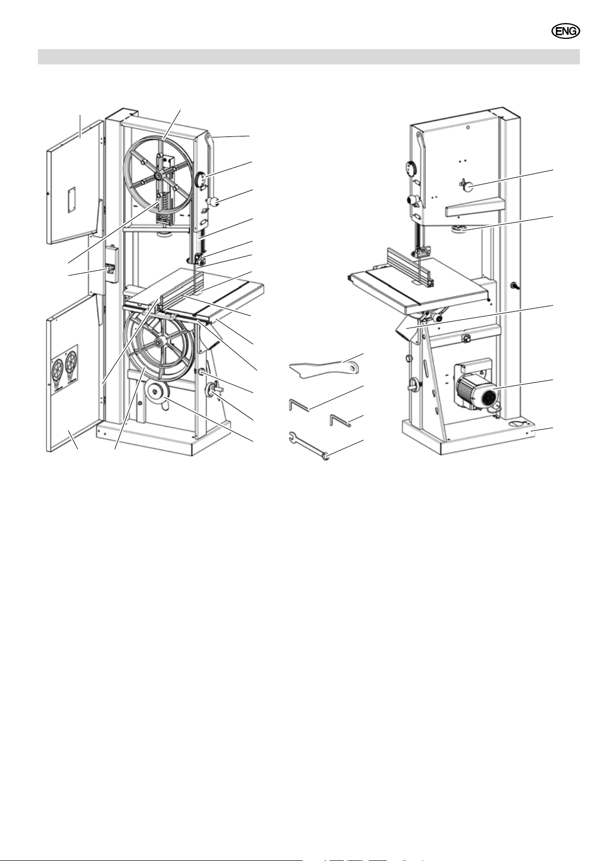
1. Parts Identification
ENGLISH
Front
1 Upper housing door
2 Upper band saw wheel
3 Push stick holder
4 Turn-lock fasterner, housing door
5 Twist handle for blade guard
6 Blade guard
7 Blade guide, upper
8 Band saw blade
9 Table insert
10 Rip fence
11 Saw table
12 Fence guide extrusion
13 Turn-lock fasterner, housing door
14 Twist handle for V-belt tension set-
ting
15 V-belt drive
16 Lower band saw wheel
17 Lower housing door
18 On/Off switch with emergency
stop
19 Blade tension indicator
Rear
20 Setting knob for blade tracking
adjustment
21 Setting knob for band saw
blade tension
22 Dust extraction port
23 Motor
24 Machine base
25 Wrench
26 Allen key
27 Push stick
15
Page 3
ENGLISH
Table of Contents
1. Parts Identification....................15
2. Please Read First!.....................16
3. Initial Operation.........................16
4. Safety .........................................16
4.1 Specified conditions of use .........16
4.2 General Safety Instructions.........16
4.3 Symbols on the machine.............18
4.4 Safety devices.............................18
5. Transport ...................................18
6. Machine details .........................18
6.1 Aligning the saw table .................19
6.2 Mounting .....................................20
6.3 Installing the Saw Table ..............20
6.4
Tensioning the Band Saw Blade
6.5 Fence guide extrusion
installation ...................................20
6.6 Rip fence installation...................20
6.7 Dust collector connection............20
6.8 Changing the Band Saw Blade ...20
6.9 Mains connection ........................21
7. Operation ...................................21
7.1 Adjusting the Upper
Blade Guide ................................22
7.2 Sawing ........................................22
8. Care and Maintenance..............22
8.1 Band saw blade alignment ..........23
8.2 Upper blade guide alignment ......23
8.3
Aligning the Lower Blade Guide
8.4 Replacing the Band Saw Tyre.....24
8.5 Replacing the Table Insert ..........24
8.6 Saw Cleaning..............................24
8.7 Saw storage ................................24
9. Tips and Tricks..........................24
10. Available Accessories ..............24
11. Repairs.......................................24
12. Environmetal Protection...........24
13. Trouble shooting.......................24
14. Technical specifications...........25
14.1 Available Band Saw Blades ........26
...20
....23
2. Please Read First!
These operating instructions have been
written to make it easier for you, the
user, to learn how to operate this
machine and to do so safely. These
instructions should be used as follows:
− Read instructions before use. Pay
special attention to the safety infor
mation.
− These instructions are intended for
persons with basic technical knowl
edge regarding the operation of a
device like the one described
herein. If you have no experience
whatsoever, you are strongly
-
-
advised to seek competent advise
and guidance from an experienced
person before operating this
machine.
− Keep all documents supplied with
this machine for future reference.
Retain your proof of purchase in
case of a future warranty claim.
− If you lend or sell this machine be
sure to have these instructions go
with it.
− The equipment manufacturer is not
liable for any damage resulting from
neglect of these operating instruc
tions.
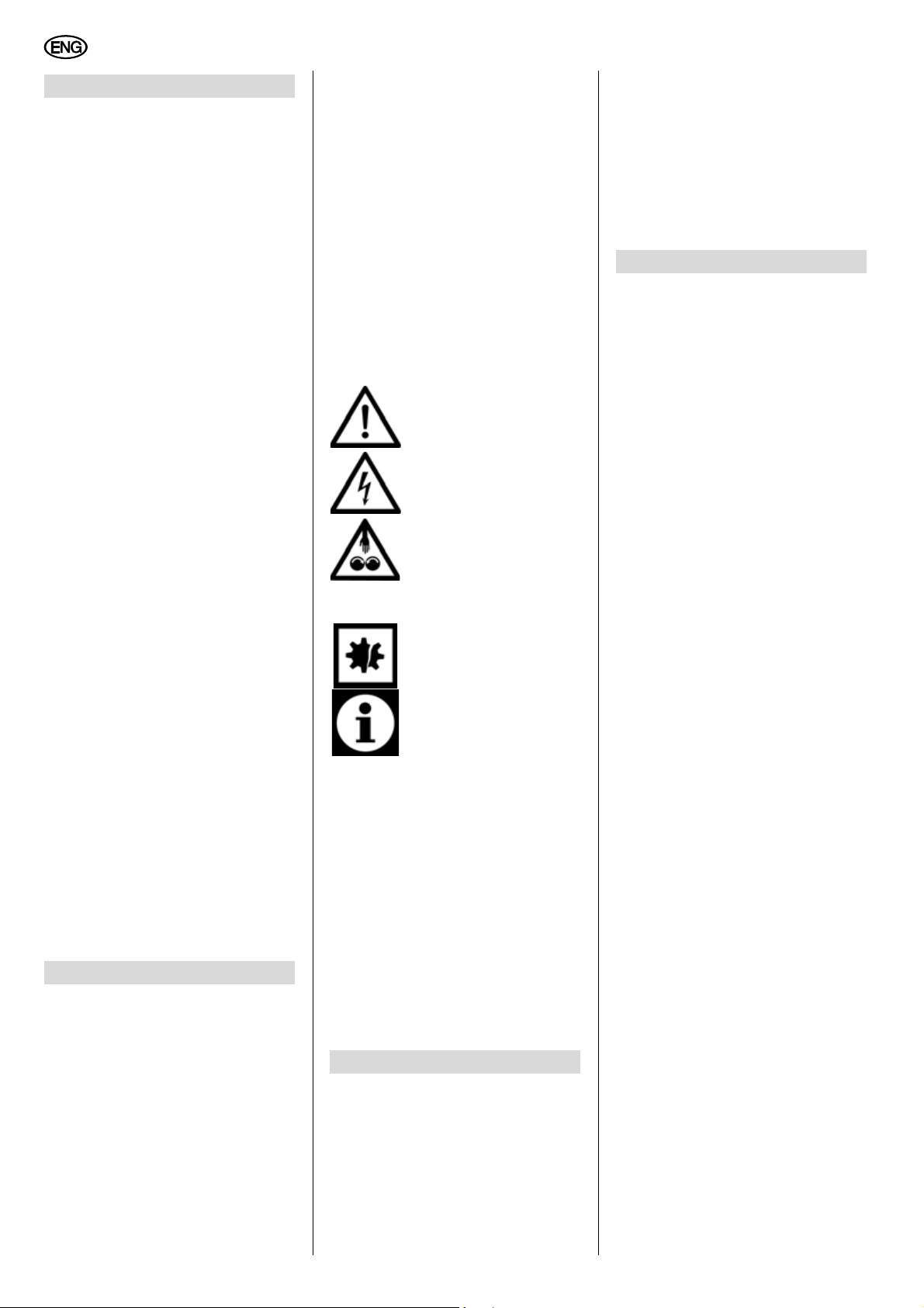
Information in this manual is denoted as
follows:
Danger!
Risk of personal injury or
environmental damage.
Risk of electric shock!
Risk of personal injury
by electric shock.
Drawing-in/trapping hazard!
Risk of personal injury
by body parts or clothing
being drawn into the
rotating saw blade.
Caution!
Risk of material damage.
Note:
Additional information.
− At times numbers are used in illustrations (1, 2, 3, ...). These numbers
− indicate component parts;
− are consecutively numbered;
− correspond with the number(s) in
brackets (1), (2), (3) ... in the
neighbouring text.
− Numbered steps must be carried out
in sequence.
− Instructions which can be carried
out in any sequence are marked
with a bullet (•).
− Listings are indicated by an En Dash
(–).
3. Initial Operation
A
Danger!
Start the saw only after the following
preparations have been completed:
− saw is mounted;
− saw table is installed and aligned;
− the V-belt tension checked;
− safety devices have been
checked.
− Connect the saw to the mains
supply only after all of the above
preparations are completed! Oth
erwise there is a risk of an unintentional starting of the saw,
which can cause severe personal
injury.
4. Safety
4.1 Specified conditions of
-
use
This machine is intended for indoor use
in dry rooms only. Any outdoor use is not
permitted!
The machine is suitable for cutting wood,
wood-derived materials and plastics.
Do not cut round stock transverse to its
longitudinal axis without suitable jigs or
fixtures. The rotating saw blade could
turn the work piece.
When sawing thin stock layed on edge,
a suitable guide must be used for firm
support.
Any other use is not as specified. The
manufacturer is not liable for any damage caused by unspecified use.
Modification of the machine or use of
parts not approved by the equipment
manufacturer can cause unforeseeable
damage!
4.2 General Safety Instructions
• When using this machine observe
the following safety instructions, to
minimize the risk of personal injury
or material damage.
• Please also observe the special
safety instructions in the respective
sections.
• Where applicable, follow the legal
directives or regulations for the pre
vention of accidents pertaining to
the use of band saws.
A
General hazards!
• Keep your work area tidy – a messy
work area invites accidents.
• Be alert. Know what you are doing.
Set out to work with reason. Do not
operate device while under the influ
ence of drugs, alcohol or medication.
• Consider environmental conditions.
keep work area well lighted.
• Prevent adverse body positions.
Ensure firm footing and keep your
balance at all times.
• Use suitable workpiece supports
when cutting long stock.
-
-
-
16
Page 4

ENGLISH
• Do not operate the machine near
inflammable liquids or gases.
• The machine shall only be started
and operated by persons familiar
with bandsaws and who are at any
time aware of the dangers associ
ated with the operation of such
machine.
Persons under 18 years of age shall
use this device only in the course of
their vocational training, under the
supervision of an instructor.
• Keep bystanders, particularly children, out of the danger zone. Do not
permit other persons to touch the
machine or power cable while it is
running.
• Do not overload device – use it only
within the performance range it was
designed for (see “Technical Speci
fications”).
B
• Do not expose machine to rain.
Do not operate the machine in damp
or wet environment.
Prevent body contact with earthed
objects such as radiators, pipes,
cooking stoves, refrigerators when
operating this device.
• Do not use the power cable for any
purpose it is not intended for.
A
• Do not operate the machine without
installed guards.
• Always keep sufficient distance to
the band saw blade. Use suitable
feeding aids if necessary. Keep suf
ficient distance to driven components when operating the electric
tool.
• Wait for the band saw blade to come
to a complete stop before removing
cutoffs, scrap, etc. from the work
area.
• Cut only stock of dimensions that
allow for safe and secure holding
while cutting.
• Do not attempt to stop the band saw
blade by pushing the workpiece
against its side.
• Ensure the tool is disconnected from
power before servicing.
• When turning ON the machine (e.g.
after servicing) ensure that no tools
or loose parts are left on or in the
machine.
• Unplug the tool when not in use.
Danger! Risk of electric shock!
Risk of injury by moving parts!
-
-
-
A
Cutting hazard, even with the
cutting tool at standstill!
• Wear gloves when changing cutting
tools.
• Store band saw blades in such manner that nobody will get hurt.
A
Risk of kickback (workpiece is
caught by the band saw blade and
thrown against the operator)!
• Do not jam workpieces.
• Cut thin or thin-walled work pieces
only with fine-toothed band saw
blades. Always use sharp band saw
blades.
• If in doubt, check workpiece for
inclusion of foreign matter (e.g. nails
or screws).
• Cut only stock of dimensions that
allow for safe and secure holding
while cutting.
• Never cut several workpieces at the
same time – and also no bundles
containing several individual pieces.
Risk of personal injury if individual
pieces are caught by the band saw
blade uncontrolled.
• When cutting round stock, use a
suitable jig to prevent the workpiece
from turning.
c
Drawing-in/trapping hazard!
• Ensure that no parts of the body or
clothing can be caught and drawn in
by rotating components (no neck
ties, no gloves, no loose-fitting
clothes; contain long hair with hair
net).
• Never saw workpieces containing
the following materials:
− ropes
− strings
− cords
− cables
− wires.
A
Danger due to insufficient per-
sonal protection equipment!
• Wear hearing protection.
• Wear safety goggles.
• Wear dust mask.
• Wear suitable work clothes.
• When working outdoors wearing of
non-slip shoes is recommended.
A
Risk of injury by inhaling wood
dust!
• Some types of wood dust (e.g. oak,
beech and ash) may cause cancer
when inhaled. Work only with a suit
able dust extractor attached to the
saw. The dust collector must comply
-
-
-
with the specifications stated in the
Technical Data.
• Make sure that as little as possible
wood dust can escape into the environment:
− remove wood dust deposit in the
work area (do not blow away!);
− fix any leakages on the dust col-
lector;
− keep your work area well venti-
lated at all times.
A
Hazard generated by modification of the machine or use of parts
not tested and approved by the manufacturer!
• Strictly follow these instructions
when assembling the device.
• Use only parts approved by the
manufacturer. This applies espe
cially for:
− band saw blades (see “Technical
Specifications” for stock nos.);
− safety devices (see "Spare parts
list" for stock numbers).
• Do not change any parts.
A
Hazard generated by tool
defects!
• Keep device and accessories in
good repair. Observe the mainte
nance instructions.
• Prior to any use check the machine
for possible damage: before operat
ing the machine all safety devices,
protective guards or slightly damaged parts need to be checked for
proper function as specified. Check
to see that all moving parts work
properly and do not jam. All parts
must be correctly installed and meet
all conditions necessary for a proper
operation of the device.
• Before switching on: Check if saw
blade coasts down for more than 10
seconds; if more than 10 seconds,
have motor replaced by a qualified
electrician.
• Damaged protection devices or
parts must be repaired or replaced
by a qualified specialist. Have dam
aged switches replaced by a service
centre. Do not operate tool if the
switch cannot be turned ON or OFF.
• Keep handles free of oil and grease.
A
Danger from blocking work-
pieces or workpiece parts!
If blockage occurs:
1. Switch machine OFF.
2. Unplug mains cable.
3. Wear gloves.
4. Clear blockage with suitable tool.
17
-
-
-
-
Page 5
ENGLISH
29
30
31
32 33 35
28
34
36
37
38
36
39
40
41
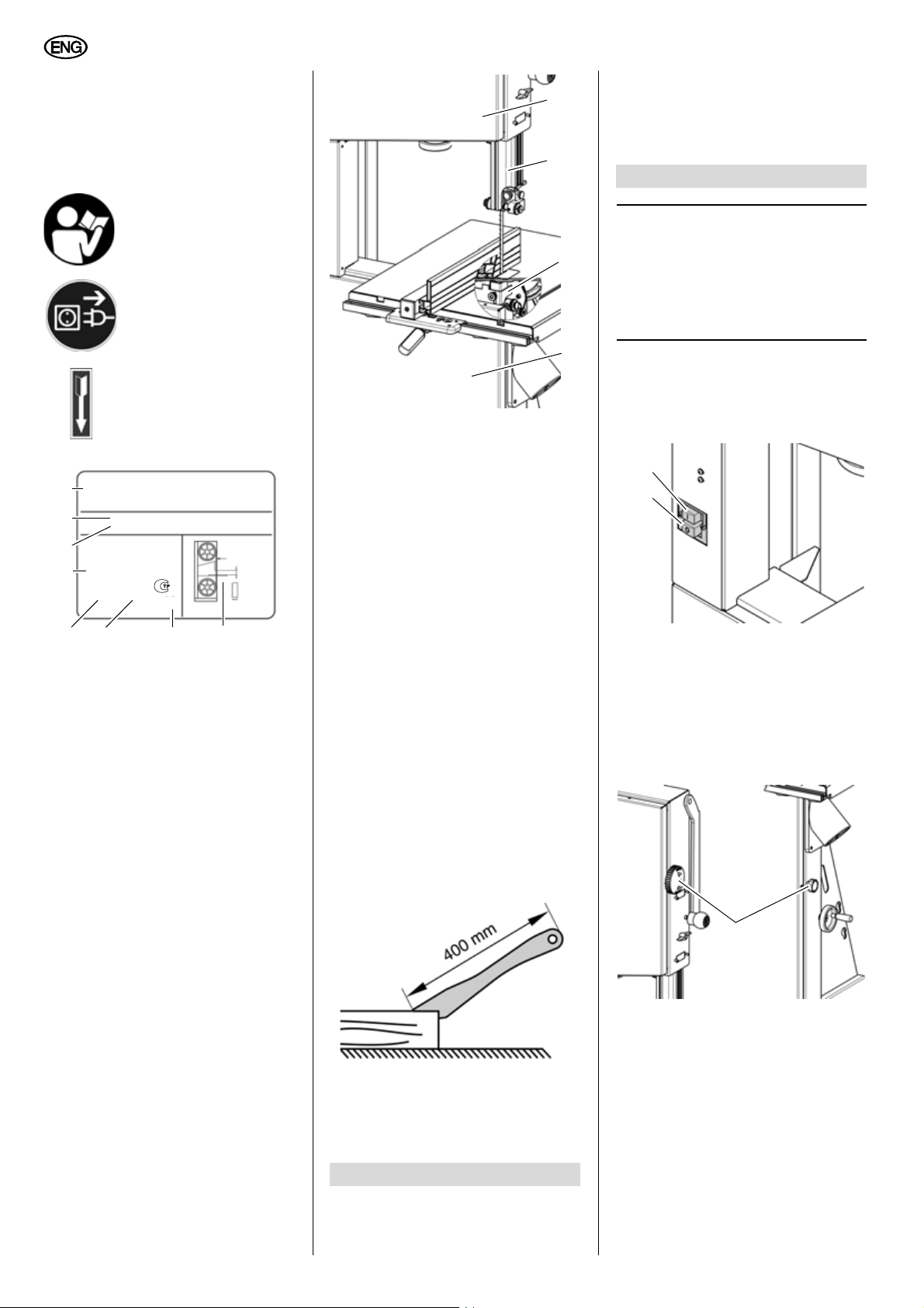
4.3 Symbols on the machine
A
Danger!
Disregard of the following warnings
could lead to serious personal injury
or material damage.
Read instructions.
Unplug mains cable.
Band saw blade running
direction.
Information on the nameplate:
Lower blade guard
The lower blade guard (38) protects
against inadvertent contact with the
band saw blade below the saw table.
The lower blade guard must be installed
during operation.
• Transport the saw with the help of a
second person.
• For transport use the original packing where possible.
6. Machine details
Note:
3
In this chapter the essential operating elements of the machine are introduced.
The proper use of the saw is detailed in
chapter “Operation”. Read this chapter
before using the saw for the first time.
ON/OFF switch
• To start = press green switch button
(39).
•
To stop = press red switch button
(40).
28 Manufacturer
29 Serial number
30 Machine designation
31 Motor specifications (see
also "Technical Specifications")
32 CE mark – This machine meets
the EC directives as per declara
tion of conformity
33 Waste disposal symbol – Device
can be disposed of by returning it
to the manufacturer
34 Date of manufacture
35 Dimensions of approved band saw
blades
4.4 Safety devices
Upper blade guard
The upper blade guard (37) protects
against unintentional contact with the
saw blade and from chips flying about.
In order for the upper blade guard to provide adequate protection against contact
with the band saw blade, it must always
be set as close as possible against the
workpiece (max. distance 3
18
mm).
Housing doors
The housing doors (36) protect against
contact with the rotating parts inside the
machine.
The housing doors are equipped with
interlocking contacts. These turn the
motor OFF when one housing door is
opened while the saw is running.
The housing doors must be closed while
the machine is in use.
Push stick
The push stick serves as an extension of
the hand and protects against accidental
-
contact with the saw blade.
The push stick must always be used if
the distance between band saw blade
and a rip fence is less than 120
Guide the push stick at an angle of
20° … 30° against the saw table's surface.
When the push stick is not used, it can
be stored on the push stick holder pro
vided at the band saw frame.
Replace the push stick if damaged.
mm.
In the event of a power failure an undervoltage relay will trip. This prevents the
starting of the machine when the power
is restored. To restart, the green switch
button must be pressed.
Turn-lock fastener, housing door
Open and close the housing door using
the turn-lock fastener (41).
Opening the housing door:
1. Rotate the upper turn-lock fastener
clockwise approx. one turn and the
lower turn-lock fastener anticlock
-
wise approx. one turn.
The housing door opens slightly.
This activates the door interlock
which switches the motor off.
-
5. Transport
• Set upper blade guide to its lowest
position.
• Remove projecting accessories.
Page 6

ENGLISH
42
43
44
+
–
45
46
47
48
49
50
A
Danger from exposed bandsaw
blades and wheels!
If after one turn the motor does not
switch off or the door immediately
opens wide, the door interlock or the
closure system is defective. Shut down
the saw and return it to the Service
Centre in your country for repair.
2. Rotate the turn-lock fastener further.
The housing door opens wide.
Closing the housing door:
• Press on the housing door and
rotate the upper turn-lock fastener
anticlockwise and the lower turnlock fastener clockwise all the way.
The housing door is completely contacting the housing.
Setting knob for band saw blade tension
With the setting knob (42) the band saw
blade tension is corrected, if necessary:
− Turning the setting knob clockwise
increases the blade tension.
−
Turning the setting knob counterclockwise reduces the blade tension.
Setting knob for drive belt tension
With the setting knob (44) the drive belt
tension is corrected, if necessary:
− Turning the adjustment knob anticlockwise decreases the blade tension.
− Turning the setting knob clockwise
increases the blade tension.
Saw table tilt
After loosening the locking screw (46)
the saw table (45) tilts steplessly through
20° against the blade.
Saw table lateral alignment
1. Loosen lock lever (48) and hexagon
nut (49).
A
Danger!
Risk of injury, even with the band saw
blade at standstill. To loosen and
tighten the fastening screws use a
tool that allows for keeping your hand
at a sufficient distance from the band
saw blade.
2. Loosen the four fastening screws
(50)
.
Setting knob for blade tracking
adjustment
With the setting knob
upper band saw wheel can be adjusted, if
necessary. This tracking adjustment is
required to have the blade run dead centre
on the rubber tyres of the band saw
wheels:
− turning clockwise = blade moves to
the rear
− Turning counter-clockwise = blade
moves to the front.
(43)
the tilt of the
Rip fence
The rip fence (47) is clamped to the
front. The rip fence can be used on both
sides of the blade.
6.1 Aligning the saw table
The saw table needs to be aligned in two
planes
− laterally, in order for the blade to run
dead centre through the table insert;
− at right angles to the band saw
blade.
3. Align saw table so that the blade
runs through the centre of the table
insert's slot.
4. Tighten the four fastening screws
(50) again.
5. Tighten hexagon nut (49) only so
much that the saw table can still
easily be tilted.
6. Tighten lock lever (48).
Aligning the saw table at right angles
to the band saw blade
1. Raise upper blade guide fully (see
“Operation”).
2. Check band saw blade tension (see
“Care and Maintenance”).
3. Loosen lock lever (48).
4. Using a try square, set the table at
right angles to the blade and tighten
the lock lever
5. Loosen locking nut (51) and adjust
limit stop screw (52) until it touches
the saw housing.
(48) again.
19
Page 7

ENGLISH
51
52
53
54
55
56
57
58
6. Tighten locking nut.
6.2 Mounting
For a firm stand the saw must be
mounted on a stable supporting floor:
1. Drill four holes in the supporting
floor.
2. Put fixing bolts through the base
plate and secure with nuts.
6.3 Installing the Saw Table
1. Fit limit stop screw (53) to the underside of the saw table.
2. Guide saw table over the band saw
blade and place it on the table trunnion.
3. Attach the saw table with four each
screws (54) and washers to the
table trunnion.
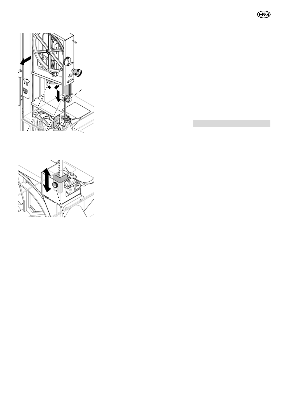
6.4 Tensioning the Band Saw
Blade
A
Danger!
Too much tension can cause the
band saw blade to break. Too little
tension can cause the driven band
saw wheel to slip and the band saw
blade to stop.
1. Raise upper blade guide fully (see
“Operation”).
2. Checking the blade tension:
− Check tension by pushing with a
finger, halfway between table and
upper blade guide, against the
side of the blade (the blade
should flex not more than 1-2
mm).
− Check adjustment at the blade
tension indicator. The scale indi
cates the correct adjustment in
dependence on the band saw
blade width.
3. Correct tension if necessary:
− turning the setting knob (55)
counter-clockwise increases the
blade tension.
− turning the setting knob (55)
counter-clockwise reduces the
blade tension.
-
6.5 Fence guide extrusion
installation
• Fasten the fence guide extrusion
(56) with four thumb screws and
washers to the saw table.
1. Place rip fence on rip fence guide.
2. Tighten lock lever (57) of rip fence.
6.7 Dust collector connection
A
Danger!
Some types of saw dust (e.g. of oak,
beech and ash wood) can cause can
cer when inhaled: always use a dust
collector when working indoors
(required air speed at the saw's suc
tion connector ≥ 20 m/s).
A
Caution!
Operation without a dust collector is
only possible:
− outdoors;
− for short-term operation
(up to 30 minutes maximum);
− with dust respirator.
− If no dust collector is used chips will
accumulate, which need to be
removed periodically.
Connect dust collector or industrial vacuum with a suitable adaptor to the dust
extraction port.
-
-
6.8 Changing the Band Saw
Blade
A
Danger!
Risk of injury, even with the band saw
blade at standstill. Wear gloves when
changing blades.
Use only suitable band saw blades
(see “Technical specifications”).
1. Loosen the four thumb screws and
remove the fence guide extrusion
(58) for the rip fence.
20
6.6 Rip fence installation
The rip fence can be used on both sides
of the blade.
2. Open housing door.
Page 8
ENGLISH
59
60
61
62
63
3. Adjust upper blade guide (59) to its
lowest position.
4. Loosen knurled nut (63) on the hand
guard and slide hand guard into its
lower position.
5. Open the lower blade guard (60).
6. Loosen setting knob (62) until the
band saw blade has slackened.
7. To remove the band saw blade,
guide it through
− the slot in the saw table,
− the blade guard on the upper
blade guide
− the lower blade guard (60) and
− the blade guides.
A
Danger!
Use a suitable transport device to
transport wide clamped saw blades.
8. Fit fresh band saw blade. Observe
correct position: the teeth point
towards the front (door) side of the
saw.
9. Center band saw blade on the rub-
ber tyres of the band saw wheels.
10. Tighten setting knob (62) until blade
does no longer slip off the band saw
wheels.
11. Clamp band saw blade (see section
"Clamping the band saw blade").
12. Close lower blade guard (60) and
slide hand guard into upper position
(61),
or against the table's edge, tighten
knurled nut
13. Close housing door.
14. Then:
− align band saw blade (see section "Aligning the band saw
blade");
− align blade guides (see “Care
and maintenance”);
− let saw test run for at least one
minute;
− stop saw, unplug and recheck
settings.
15. Fasten the fence guide extrusion
(58) to the saw table with the four
thumb screws and washers.
(63).
6.9 Mains connection
B
Danger! High voltage
• Operate saw in dry environment
only.
• Operate saw only on a power
source matching the following
requirements (see also 'Technical
Data'):
− mains voltage and system fre-
quency conform to the voltage
and frequency shown on the
device's name plate;
− fuse protection by a residual
current operated device (RCD)
of 30 mA sensitivity;
− outlets properly installed,
earthed, and tested;
− three-phase outlets with neu-
tral wire installed;
Note:
3
Check with your local Electricity
Board or electrician if in doubt whether
your house service connection meets
these requirements.
• Position power supply cable in a
way that it does not interfere with
the work and is not damaged.
• Protect power supply cable from
heat, aggressive liquids and
sharp edges.
• Use only rubber-insulated extension cables of sufficient lead
cross section (3
machines with 3-phase motor:
5 x 1.5 mm2).
• Do not pull on power supply
cable to unplug.
A
change of direction of rotation
(only for version with AC motor):
This can lead to the workpiece being
hurled away when attempting to make
a cut. The direction of rotation must
therefore be checked every time the
saw is connected to another outlet.
x 1.5 mm2, for
If the direction of rotation is incorrect,
the electrical connection must be
changed by a qualified electrician!
1. After the saw and all of its safety
devices have been assembled, con
nect it to the mains supply.
2. Start saw and switch OFF immediately.
3. Observe the correct rotational direction of the band saw blade: In the
cutting area the band saw blade
must run downwards.
4. If the band saw blade turns in the
wrong correction, unplug the power
supply cable at the saw.
5. Have the electric supply changed by
a qualified electrician!
-
7. Operation
A
Danger!
To reduce the risk of personal injury
as much as possible, the following
safety recommendations should be
observed when operating the saw.
• Use personal protection equipment:
− dust respirator;
− hearing protection;
− safety goggles.
• Cut only one work piece at a time.
• Always hold the work piece down
on the table.
• Do not jam the workpiece.
• Do not attempt to stop the band
saw blade by pushing the work
piece against its side.
• Sawing of bowed or irregular
work pieces: hold the workpiece
firmly against the table and feed
in at a uniform speed. Keep your
hands in the safe area.
• If the type of work requires, use
the following:
− push stick – if distance rip
fence – band saw blade less
≤120 mm;
than
− work support – for long stock,
which would otherwise fall off
the table on completion of the
cut;
− dust collector;
− a circle cutting device when
cutting circular pieces;
− a guide when cutting small
wedges;
− an appropriate jig when cutting
round stock, to keep it from
turning;
-
21
Page 9

ENGLISH
64
65
66
965 m/min408 m/min
− a suitable guide for firm support when cutting thin stock
layed on edge.
• Before starting work, check to
see that the following are in
proper working order:
− band saw blade;
− upper and lower blade guard.
• Replace damaged parts immedi-
ately.
• Assume correct work position
(the band saw blade's teeth must
point towards the operator).
• Never cut more than one workpiece at a time – and also no bundles containing several individual
pieces. Risk of personal injury if
individual pieces are caught by
the saw blade uncontrolled.
c
Drawing-in/trapping hazard!
• Do not wear loose clothing, jewellery, or gloves, which may get
caught and wound up by revolv
ing machine parts.
• Contain long hair with a hairnet.
• Never cut stock to which ropes,
cords, strings, cables and wires
are attached or which contain
such materials.
7.1 Adjusting the Upper
Blade Guide
The height of the upper blade guide (66)
needs to be adjusted:
− prior to every cutting operation, to
accommodate the height of the
workpiece (the upper blade guide
should be set approx. 3 mm above
the workpiece);
− after adjustments of band saw blade
or saw table (e.g. band saw blade
change, tensioning of the band saw
blade, saw table alignment).
A
Danger!
Turn the machine OFF and wait for
the band saw blade to stop before
adjusting the upper blade guide or
the saw table.
1. Loosen screw (65).
2. Set the upper blade guide (66) with
the twist handle (64) to the desired
height.
3. Re-tighten screw (65).
Cutting speed adjustment
1. Open the lower housing door.
2. Slacken the V-belt by turning the
tension crank handle anticlockwise.
3. Put V-belt on the required pulley of
the driving wheel (lower band saw
wheel) and the corresponding motor
pulley – note label inside the lower
housing door.
-
A
Caution!
The V-belt must run either on both
front or both rear pulleys. Never have
the V-belt run diagonally!
− V-belt on front pulley
= low speed, high torque.
− V-belt on rear pulleys
= high speed, low torque.
4. Re-tighten the V-belt by rotating the
crank clockwise (the V-belt must be
able to be depressed in the middle
about 10
5. Close the lower housing door.
mm).
7.2 Sawing
1. Check the band saw blade tension
(see 'Tensioning the band saw
blade').
2. If necessary, adjust the table tilt.
3. Select rip fence and table tilt for the
type of cutting operation to be carried out.
A
Hazard generated by a jam-
ming workpiece!
When sawing with the rip fence and a
tilted saw table, the rip fence must be
installed on that side of the saw table
which is tilted downward.
4. Set upper blade guide 3 mm above
the workpiece.
Note:
3
Always make a trial cut in a piece
of scrap to verify settings; correct if necessary before cutting the workpiece.
5. Place workpiece on the saw table.
6. Start saw.
7. Cut workpiece in a single pass.
8. Switch off if no further cutting is to
be done immediately afterwards.
9. If no further cutting is to be done
immediately afterwards: decrease
the bandsaw blade tension and
attach a notice indicating that the
bandsaw blade tension must be
reset prior to the next cutting opera
tion to the machine (see 'Tensioning
the bandsaw blade').
8. Care and Maintenance
A
Danger!
Prior to all servicing:
1. switch machine OFF;
2. Wait for saw blade to stop
3. Unplug mains cable.
− Check that all safety devices are
operational again after each service.
− Replace damaged parts, especially
safety devices, with genuine
replacement parts only, since parts
not tested and approved by the
manufacturer can cause unforesee
able damage.
− Repair and maintenance work other
than described in this section should
only be carried out by qualified spe
cialists.
-
-
-
22
Page 10

ENGLISH
965 m/min408 m/min
67
68
69
70
71
73
72
74 75 76
77
78
79
8081
A
Danger!
If the table insert is damaged, small
objects may get caught between the
table insert and the kerf plate and
block the saw blade. Replace dam
aged table inserts immediately!
Speed adjustment
By shifting the drive belt the band saw
can be operated at two speeds (see
“Technical specifications”):
− 408 m/min for hard wood, plastics
and non-ferrous metals (with special
band saw blade);
− 965 m/min for all kinds of wood.
A
Caution!
The drive belt must not run in a diagonal position; this will damage the belt
-
8.1 Band saw blade alignment
If the band saw blade does not run in the
centre of the rubber tyres, the tracking
needs to be corrected by adjusting the
tilt of the upper band saw wheel:
1. Loosen lock nut (68).
2. Setting knob (67):
− Turn setting knob (67) clockwise
if the band saw blade runs
towards the front of the saw.
− Turn setting knob (67) counter-
clockwise if the band saw blade
runs towards the rear of the saw.
− a thrust bearing (supports the band
saw blade from the rear),
− two guide bearings (providing lateral
support).
All bearings need to be readjusted after
every band saw blade change or tracking.
Note:
3
Periodically check all bearings for
wear, if necessary replace both guide
bearings at the same time.
Adjusting the thrust bearing
1. If necessary, align and tighten the
band saw blade.
2. Loosen the thrust bearing's (69) lock
screw (70).
3. Adjust thrust bearing position (dis-
tance thrust bearing - band saw
blade = 0.5 mm – if the band saw
blade is turned by hand, it must not
touch the thrust bearing).
4. Tighten the thrust bearing lock
screw.
Adjusting the guide bearings
1. Loosen knurled nut (72).
2. Set guide bearings (73) with the
knurled thumb screws (71) against
the band saw blade.
8.3 Aligning the Lower Blade
Guide
The lower blade guide consists of:
− a thrust bearing (supports the band
saw blade from the rear),
− two guide bearings (providing lateral
support).
These parts need to be readjusted after
every band saw blade change or tracking adjustment:
Note:
3
Periodically check thrust bearings
and guide bearings for wear, if neces
sary replace both guide bearings at the
same time.
Basic alignment
1. Open the lower housing door.
2. Slide hand guard into lower position
and open lower blade guard
3. Loosen the screw (75) for the lower
blade guide.
4. Adjust position of lower blade guide
until band saw blade is centred
between the guide bearings (76).
5. Tighten screw (75).
Adjusting the thrust bearing
1. Loosen the thrust bearing's lock
(80).
screw
2. Adjust thrust bearing position (81)
(distance thrust bearing - band saw
blade = 0.5 mm – if the band saw
blade is turned by hand, it shall not
touch the thrust bearing).
3. Tighten the thrust bearing lock
(80).
screw
-
(74).
3. Tighten locking nut (68).
8.2 Upper blade guide alignment
The upper blade guide consists of:
3. Turn band saw wheel by hand in a
clockwise direction several times to
bring the guide bearings in correct
position – both guide bearings
should just touch the band saw
blade.
4. Retighten knurled nut (72) to lock
the knurled thumb screw (71).
Adjusting the guide bearings
1. Loosen the knurled nut (78).
23
Page 11

ENGLISH
82
2. Set guide bearings (77) with the
knurled thumb screws (79) against
the band saw blade.
3. Turn band saw wheel by hand clockwise a few times to ensure that the
guide bearings are in correct position – both guide bearings should be
lightly touching the band saw
blade.
4. Retighten knurled nut (78) to lock
the knurled thumb screw .
5. Close lower blade guard (74)
6. Close the lower housing door.
8.4 Replacing the Band Saw
Tyre
Periodically check band saw tyres for
wear. Replace only in pairs:
1. Remove band saw blade (see “Care
and maintenance”);
2. Lift band saw tyre with a small
screwdriver, then pull off the band
saw wheel.
in your hand when the saw is in operation!
Prior to all servicing:
1. Switch machine OFF.
2. Wait for saw blade to stop
3. Unplug power cable.
Saw Cleaning
1. Open housing door.
2. Remove chips and saw dust with
brush or vacuum cleaner.
3. Close housing door.
8.7 Saw storage
A
Danger!
Store saw so that
− it cannot be started by unauthorised persons and
− nobody can get hurt.
A
Caution!
Do not store saw unprotected outdoors or in damp environment.
H Dust collector
helps to protect your health and to
keep the shop clean.
I WAXILIT Sliding Compound
Improves workpiece sliding on the
saw table.
J Care and Maintenance Spray
For removing resin residue and preserving metal surfaces.
K Sanding Belt
80 grit, 3380 x 25 (pack of 3)
L Sanding Belt
120 grit, 3380 x 25 (pack of 3)
M Band Saw Blade A6
For cutting NF-metals
N Band Saw Blade A4
For contour cutting and small radii.
O Band Saw Blade A6
For cutting wood, straight cuts.
P Band Saw Blade A6
For cutting wood, universal cuts.
Q Band Saw Blade A8
For cutting firewood.
11. Repairs
3. Mount new band saw tyres and reinstall the band saw blade.
8.5 Replacing the Table
Insert
The table insert needs replacement
when its slot has become enlarged or
damaged.
1. Remove table insert (82) from saw
table (push up from underneath).
2. Fit new table insert.
8.6 Saw Cleaning
A
Danger!
Never touch the band saw blade or
the band saw wheel with a brush held
A
Caution!
Fold bandsaw blades when not in use
and store dry.
9. Tips and Tricks
• Keep surfaces of the saw table
clean – in particular, remove resin
residue with a suitable cleaning and
maintenance spray (optional acces
sory).
• Afterwards, apply a light coat of sliding compound (e.g. Waxilit).
-
10. Available Accessories
For special tasks the following accessories are available at your specialised
dealer – see back cover for illustrations:
A Circle Cutting Attachment
For cutting circles of 120 to 260 mm
diameter. Optimal cutting results
when using a band saw blade for
contoured cutting and radii.
B Wheel Set
For easy transport.
C Rip Fence
For making accurate long cuts.
D Mitre Fence Steplessly adjustable
mitre angle from 90 ° to 45°.
E Precision Roller Guide
Provides optimal band saw blade
guiding and prolonged service life.
F Belt Sanding Attachment
For finishing cut edges.
G Dust collection adapter for Ø 100
mm port.
A
Danger!
Repairs to electric tools must only be
carried out by qualified electricians!
Electric tools in need of repair can be
sent to the Service Centre of your country. Refer to the spare parts list for the
address.
Please attach a description of the fault to
the electric tool.
12. Environmetal Protection
The machine's packing can be 100%
recycled.
Worn out power tools and accessories
contain considerable amounts of valuable raw and rubber materials, which are
recyclable.
These instructions are printed on paper
produced with elemental chlorine-free
bleaching process.
13. Trouble shooting
A
Danger!
Before carrying out any fault servicing, always do the following:
1. switch machine OFF;
2. Unplug mains cable.
3. Wait until the band saw blade has
come to a complete stop.
Check to see that all safety devices
are operational after each fault serv
ice.
-
24
Page 12

ENGLISH
Motor does not run
Undervoltage relay tripped by power failure:
− switch on again.
No mains voltage
− check cable, plug, outlet and mains
fuse.
Band saw blade wanders off the line
of cut or runs off the band saw
wheels
Band saw blade is not running properly
on the band saw wheels:
− Correct tracking (see “Care and
Maintenance”).
Band saw blade breaks
Incorrect tension:
− correct band saw blade tension (see
“Care and Maintenance”).
Load too high:
− reduce pressure against band saw
blade (reduced feed rate).
Incorrect band saw blade:
− replace band saw blade (see “Care
and Maintenance”):
Contour cuts =
narrow band saw blade,
Straight cuts =
wide band saw blade.
Band saw blade warped
Load too high:
− avoid lateral pressure on the band
saw blade.
Saw vibrates
Insufficient mounting:
− Fasten saw properly to a suitable
floor (see “Initial Operation”).
Saw table loose:
− Align and fasten saw table.
Motor mount loose:
− Check fastening screws, tighten if
necessary.
Dust extraction port blocked
No dust collector connected or suction
capacity insufficient:
− Connect a dust collector or increase
suction capacity (air speed ≥20 m/
sec at dust extraction port).
14. Technical specifications
WNB DNB
Voltage V 230 (1~ 50 Hz) 400 (3~ 50 Hz)
Nominal current A 6,7 3,9
Fuse protection A 10 (time-lag or K-Auto-
mat)
10 (time-lag or K-Auto-
mat)
Protection rating IP 54 IP 54
Protection class I I
Performance
Power input P1
effective shaft output P2
Rated no-load speed min
kW
kW
-1
1.50 kW S6 40%
1.10 kW S6 40%
1400 1400
1.90 kW S6 40%
1.50 kW S6 40%
Cutting speed m/min 408/965 408/965
Band saw blade length mm 3380 3380
Max. throat capacity mm 440 440
Max. capacity under guide mm 280 280
Max. band saw blade width mm 25 25
Max. band saw blade thickness mm 0,65 0,65
Dimensions
Machine in packing
− Length
− Width
− Height
mm
mm
mm
790
710
1970
790
710
1970
Machine ready for work (saw table horizontal)
− Length
− Width
− Height
mm
mm
mm
834
639
1860
834
639
1860
Saw table only
− Length
− Width
mm
mm
640
536
640
536
Weight
Machine ready for work (with accessories supplied) kg 133 133
Permissible ambient temperature for operation
Permissible temperature for transport and storage
° C
° C
0 to +40
0 to +40
0 to +40
0 to +40
Noise emission value (DIN EN 1870-1*) at idle
A-sound pressure level LpA
A-sound power level
LWA
Uncertainty K
dB (A)
dB (A)
dB (A)
75,0
84,6
4,0
75,0
84,6
4,0
25
Page 13

ENGLISH
WNB DNB
Noise emission value (DIN EN 1870-1*) during sawing
A-sound pressure level LpA
A-sound power level
Uncertainty K
* The values stated are emission values and as such do not necessarily constitute values which are safe for the workplace.
Although there is a correlation between emission levels and environmental impact levels, whether further precautions are neces
sary cannot be derived from this. Factors influencing the actually present environmental impact level in the workplace include the
characteristics of the work area and other noise sources, i.e. the number of machines and other neighbouring work processes. Also,
permissible workplace values may vary from country to country. This information is intended to assist the user in his estimate of
hazards and risks.
LWA
14.1 Available Band Saw
Blades
Application Dimensions mm Tooth spacing Stock number
NF-metals 3380 x15 x 0.5 A2 090 902 9210
Contour cutting 3380 x 6.0 x 0.5 A4 090 902 9180
Wood – straight cuts 3380 x 25 x 0.5 A6 090 900 0416
Wood – universal cuts 3380 x 15 x 0.5 A6 090 902 9171
dB (A)
dB (A)
dB (A)
82,2
89,9
4,0
82,2
89,9
4,0
-
Firewood 3380 x 25 x 0.5 A8 090 900 0424
26
Page 14

Metabowerke GmbH,
72622 Nürtingen, Germany
www.metabo.com
 Loading...