

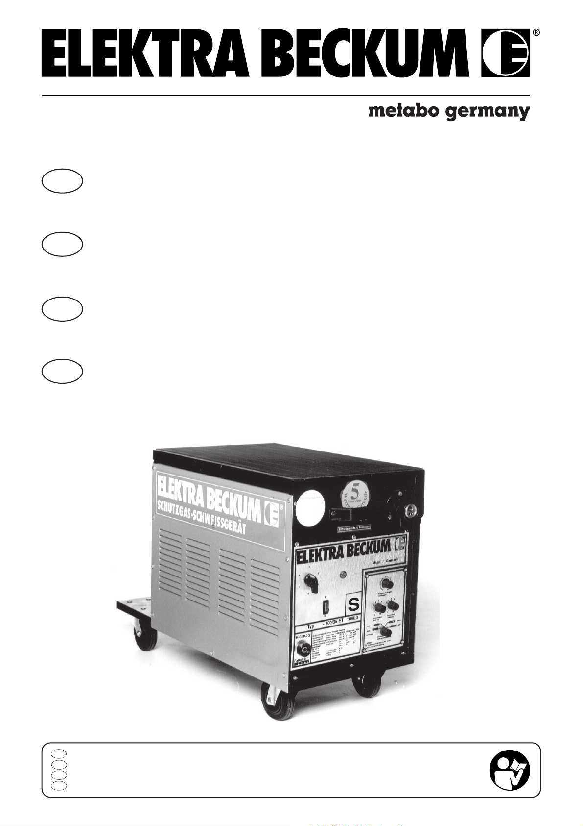
Page 1
D
Betriebsanleitung
Schutzgas-Schweißgeräte MIG/MAG 170 - 230
GB
F
NL
Operating Instruction
MIG Welding Machines 170 - 230 Amp Models
Notice d´utilisation postes de soudure
semiautomatiques MIG/MAG 170 - 230
Gebruiksaanwijzing
Lasapparaat MIG/MAG 170/230
D
Achtung! Lesen Sie diese Anleitung vor der Installation und Inbetriebnahme aufmerksam durch.
GB
Attention! Carefully read through these instructions prior to installation and commissioning.
F
Attention! Prière de lire attentivement la présente notice avant l'installation et la mise en service.
NL
115 117 3671 / D/GB/F/NL /1303 - 5.1
Attentie! Lees deze instructies voor de installatie en ingebruikname aandachtig door.
Page 2

Contents
1 Specifications
2 Regulations for the Prevention of Accidents
2.1 Welding Output
3 Operation
4 Installing the Wire Spool
5 Welding Stainless Steel and Aluminium
6 Practical Hints for MIG Welding
7 Maintenance
8 Trouble Shooting
9 Spare Parts List and Accessoires
User Responsibility
This machine will perform in conformity with the description contained in the instructions provided.
This machine must be checked periodically. Defective equipment (including service leads) should not be used.
Parts that are broken, missing, plainly worn, distorted or contaminated, should be replaced immediately. Should
such repair or replacement become neccessary, it is recommended that such repairs are carried out by qualified
persons approved by the equipment manufacturer or its representative. The user of this machine shall have the
sole responsibility for any malfunction which results from improver use or unauthorized modification from standard
specifications, faulty maintenance, damage or improper repair by anyone other than qualifieded persons approved
by the equipment manufacturer or its representatives.
Read and understand this manual before commissioning your machine!
We reserve the right to change specifications.
GB
Product Liability/Warranty
These welding machines shall only be used as specified. Any other use requires the written consent of Metabo GmbH,
Business Unit Elektra Beckum, P.O.Box 1352, D-49703 Meppen, Germany.
This product carries 2 years (5 years on main transformer and choke) manufacturer warranty under the prevailing legal
provisions, which may vary from country to country. Retain proof of purchase! You are only entitled to claim warranty
against proof of purchase. Please see back cover for manufacturer representative's address nearest you.
The warranty period begins with the date of the original purchase by the end user. Proof of purchase should be retained
and must be presented in the event of a warranty claim. This warranty excludes and does not cover defects, malfunction
and failure caused by natural wear, overload, unreasonable use or failure to provide reasonable and necessary
maintenance.
In case of a defect notify your dealer or Elektra Beckum distributor, who will decide how to handle your claim. Warranty
claims can only be taken care of by your Elektra Beckum dealer or authorized service centre.
1 Specifications
MIG/MAG MIG/MAG
170/30 TL 170/30 TL Combi
Welding range 25 - 160 A 25 - 160 A
Open-circuit voltage 15.3 - 22 V 15.3 - 22 V
No-load voltage 19 - 37 V 19 - 38 V
Input capacity 4.0 kVA 3.6/4.0 kVA
Mains 50/60 Hz AC 1 ~ 230 V 1 ~ 230/2 ~ 400 V
Frequency 50-60 Hz 50-60 Hz
Welding steps 6 6
Wire diameter 0.6 - 0.8 mm 0.6 - 0.8 mm
Weldable material 0.5 - 5 mm 0.5 - 5 mm
Duty cycle (25°c/ 40°C ) 160 A 30%/20% 160 A 30%/20%
100% (25°c/ 40°C ) 90 A/60A 90 A/60A
Mains fuse T 16 A T 16 A
Cooling F F
Protection class IP 21 IP 21
Isulation class F F
Welding gun assembly SB 14/2 SB 14/2
Dimensions l x w x h 840x410x580 840x410x580
Weight 61 kg 62 kg
Page 3

MIG/MAG MIG/MAG MIG/MAG
180/35 ET 200/35 ET 230/40 ET
Combi
Welding range 25 - 180 A 25 - 200 A 25 - 230 A
Open-circuit voltage 15.3 - 23 V 15.3 - 24 V 15.3 - 25,5 V
No-load voltage 17.5 - 33 V 21 - 34 V 19 - 34 V
Input capacity 3.6/4.6 kVA 6 kVA 6.5 kVA
Mains 50/60 Hz AC 1 ~ 230 V/2 ~ 400 V 3 ~ 400 V 3 ~ 400 V
Frequency 50-60 Hz 50-60 Hz 50-60 Hz
Welding steps 6 6 6
Wire diameter 0.6 - 0.8 mm 1,0 mm 0.6 - 1.0 mm
Weldable material 0.5 - 6 mm 0.5 - 7 mm 0.6 - 9 mm
Duty cycle (25°c/ 40°C ) 180 A 35%/25% 200 A 35%725% 230 A 40%/30%
100% (25°c/ 40°C ) 100 A/70A 110 A/75A 140 A/100A
Mains fuse T 16 A T 16 A T 16 A
Cooling F F F
Protection class IP 21 IP 21 IP 21
Isulation class F F F
Welding gun assembly SB 15/2 SB 15/2 SB 25/2
Dimensions l x w x h 840x410x580 840x410x580 840x410x580
Weight 68 kg 75 kg 81HAM kg
StandardScope of delivery: Welding machine with MIG/MAG torch c/w contact tip and gas shroud, pressure
regulator for shielding gas, earth clamp, wire brush and nozzle anti-clogging spray.
delivery:
2 Regulations for the Prevention of Accidents
Know the applicable regulations for electric arc welding and strictly adhere to.
Safety Instructions
● Protection against electrical accidents
- Welding cables are to be firmly connected to ensure proper conducting capacity
- Mains cord and welding cables are to be protected against damages.
- Replace damaged mains cords with genuine Elektra Beckum parts only.
- Place welding gun onto insulating backing during short work break.
- For longer breaks switch off machine.
- When welding, wear dry and insulating gloves and shoes.
- For maintenance and repair work disconnect from power mains.
● Protection against UV rays, burns and fumes
- Wear protective clothing to prevent burns (sleeved gloves, welding apron etc.)
- Always use a welding visor.
- Screen off work place to protect other persons working nearby against UV rays.
- Welding material having a polluted or contaminated surface may generate toxic fumes. Clean surface before
welding.
- Zinc-plated or galvanized material should not be welded as zinc fumes are highly toxic.
Page 4
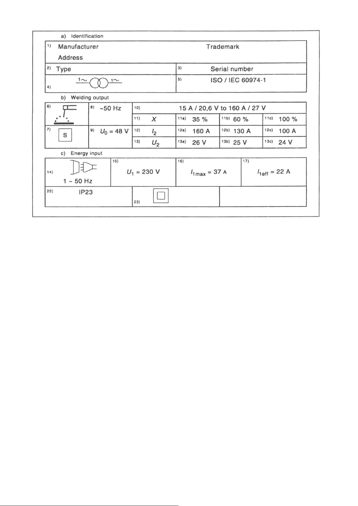
2.1 Welding Output
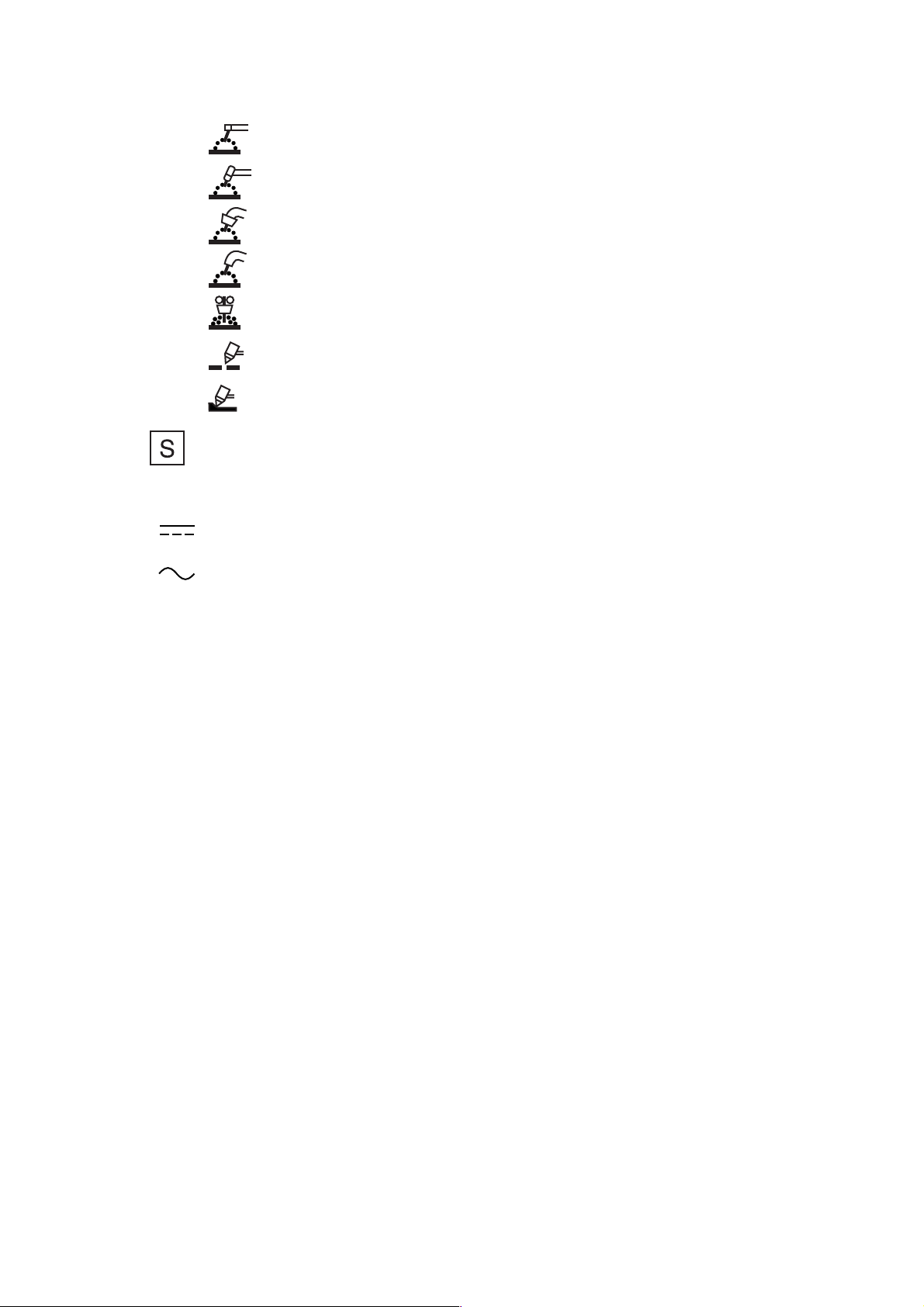
Box 6 Welding process Symbol e.g.:
Manual metal arc welding with covered electrodes
Tungsten inert-gas welding
Metal inert and active gas welding including the use of flux cored wire
Selfshielded flux cored arc welding
Submerged arc welding
Symbol for plasma cutting
Symbol for plasma gouging
Box 7 Symbol for welding power sources which are suitable for supplying power to welding operations
carried out in an environment with increased hazard of electric shock (if applicable).Box 8
Welding current symbol e.g.:
Direct current
Alternating current, and additionally the rated frequency in
hertz e.g.: ~50 Hz
Box 9 U0... V Rated no-load voltage
a) Arithmetic mean value in case of direct current
b) RMS value in case of alternating current
c) Ur... V Reduced rated no-load voltage in case of a voltage reducing device
d) Us... V Switched rated no-load voltage in case of an a.c. to d.c. switching device
Box 10 ... A/... V to... A/... V Range of output, rated minimum and maximum welding current and their
corresponding conventional load voltage.
Box 11 X Duty cycle (duty factor) symbol.
Box 12 I2 Rated welding current symbol.
Box 13 U2 Conventional load voltage symbol.
Boxes 11a, 11b, 11c ...% Values of the duty cycle (duty factor).
12a, 12b, 12c ... A Values of the rated welding current.
13a, 13b, 13c ... V Values of the conventional load voltage.
These boxes form a table with corresponding values of the three settings:
a) ... % duty cycle (duty factor) at the rated maximum welding current;
b) 60 % duty cycle (duty factor);
and
Page 5
b) Welding Output
Box 6 Welding process Symbol e.g.:
Manual metal arc welding with covered electrodes
Tungsten inert-gas welding
Metal inert and active gas welding including the use of flux cored wire
Selfshielded flux cored arc welding
Submerged arc welding
Symbol for plasma cutting
Symbol for plasma gouging
Box 7 Symbol for welding power sources which are suitable for supplying power to welding operations
carried out in an environment with increased hazard of electric shock (if applicable).
Box 8 Welding current symbol e.g.:
Direct current
Alternating current, and additionally the rated frequency in
hertz e.g.: ~50 Hz
Box 9 U0... V Rated no-load voltage
a) Arithmetic mean value in case of direct current
b) RMS value in case of alternating current
c) Ur... V Reduced rated no-load voltage in case of a voltage reducing device
d) Us... V Switched rated no-load voltage in case of an a.c. to d.c. switching device
Box 10 ... A/... V to... A/... V Range of output, rated minimum and maximum welding current and their
corresponding conventional load voltage.
Box 11 X Duty cycle (duty factor) symbol.
Box 12 I2 Rated welding current symbol.
Box 13 U2 Conventional load voltage symbol.
Boxes 11a, 11b, 11c ...% Values of the duty cycle (duty factor).
12a, 12b, 12c ... A Values of the rated welding current.
13a, 13b, 13c ... V Values of the conventional load voltage.
These boxes form a table with corresponding values of the three settings:
a) ... % duty cycle (duty factor) at the rated maximum welding current;
b) 60 % duty cycle (duty factor);
and
c) 100 % duty cycle (duty factor) as far as relevant.
Page 6
Column a) need not be used if the duty cycle (duty factor) for the rated maximum welding
current is 60 % or 100 %.
Column b) need not be used if the duty cycle (duty factor) at the rated maximum welding current is 100 %.
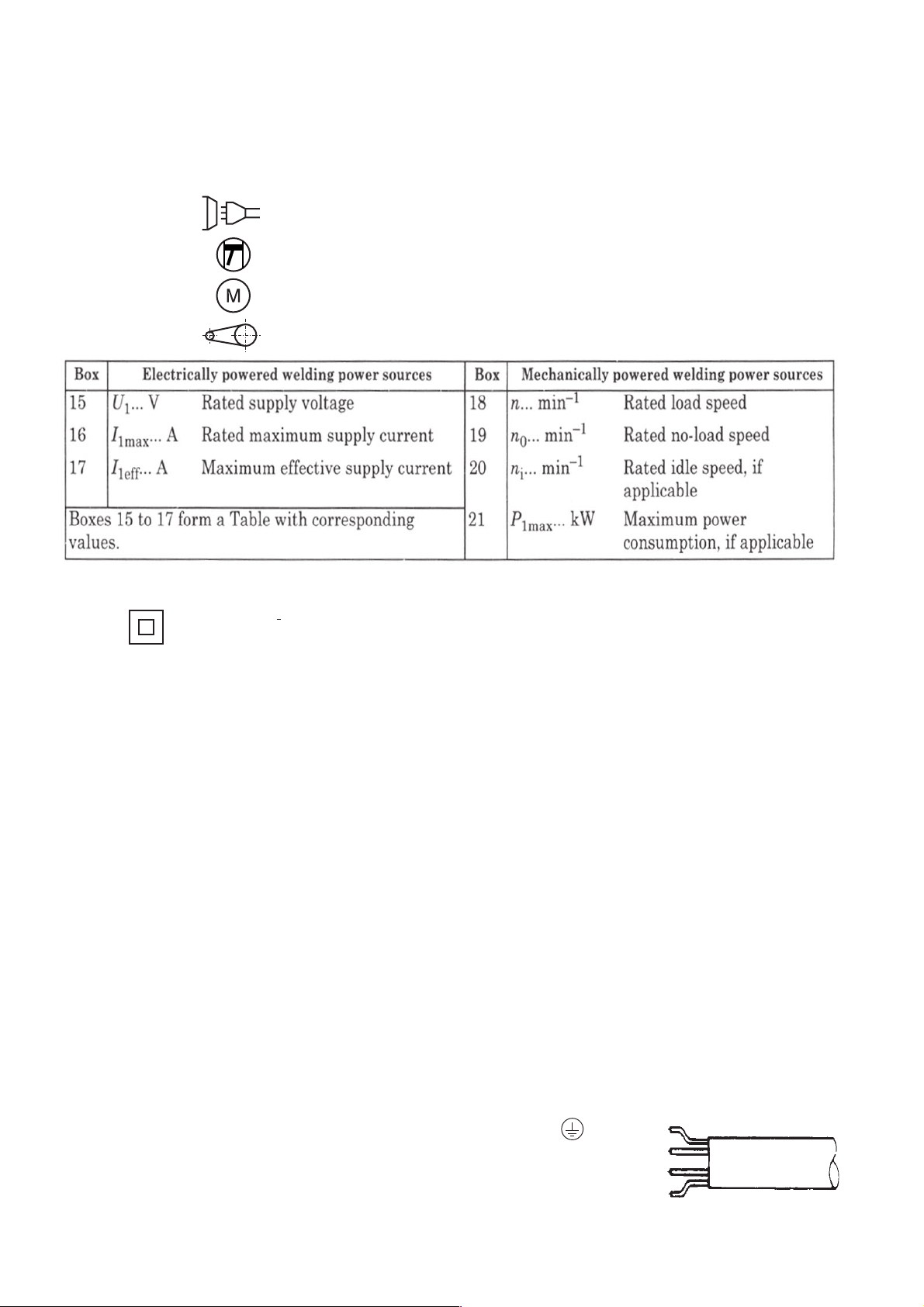
c) Energy input
Box 14 Energy input symbol e.g.:
Input supply, number of phases (e.g. l or 3), symbol for
alternating current
and the rated frequency (e.g. 50 Hz or 60 Hz)
Engine
Motor
Belt drive
Box 22 IP.. Degree of protection, e.g. IP21 or IP23.
Box 23 Symbol for protection class II, if applicable.
3 Operation
Initiation
Connect cable assembly to central coupling (1). Be sure that collar nut is fully tightened. Plug earth cable into socket
(7) and lock in position.
Place gas sylinder onto rack at rear of machine and secure with chain. Attach gas hose to pressure regulator and
secure with hose clamp provided.
Open gas cylinder valve briefly to clear any foreign matter from it, than attach pressure regulator.
Set regulator to required gas flow rate (approx. 10 - 13 ltr./min. - 2.5 - 3 GPM).
Caution: Do not dismantle the pressure regulator for any reason. It may explode when assembled incorrectly!
1-Phase Machines
These machines come fitted with a Schuko 2-prong
plug with earth contact as standard. For the U. K. and
certain other markets machines are supplied without
a plug on the power cord. Connect to power mains
only by earthed plug and earthed receptacle matchine
your local standard. Mains furse 16 amp time-lag
required.
3-Phase Machines
Three-phase machines are supplied with a CEE 5-pin
plug on the power cord. If a plug matching your local
standard has to be installed, connect only as shown at
right. The yellow/green earth lead must be connected
to the terminal marked .
Wiring diagram for Elektra Beckum
3 phase MIG welding machines
earth lead yellow/green
L1
L2
L3
Page 7

230 V/ 400 V
Combi Machines
Combi models come with a CEE 3-phase 5 prong plug
fitted to power cord as standard, and an adaptor with
1-phase plug.
If a 3-phase plug matching your local standard outlet
has to be installed, connection has to be made to 2
phases, neutral and earth.
zero/neutal lead blue
earth lead yellow/green
For 380/415 V operation
connect to 2 phases + zero
and earth lead
L1 black
L2 brown
Caution: Have machine connected to power mains by a qualified electrician only!
Neon Control Light
Central coupling KZ 2
for welding gun
Welding step selector
Mains on/off switch
Earth cable socket
4 Installing the Wire Spool
4.1 Disconnect from power mains
Place wire spool onto spool carrier so that wire runs off clockwise.
Wire feed regulator
Weld time pot
Dwell time pot
Welding mode selector
(E-models only)
Page 8

4.2 Wire Feed Set-up
Lever
The feed roller is fitted with four pilot grooves for
wire diameters 0.6/0.8/1.0/1.2 mm.
Central coupling
To adapt the feed roller to the wire size used,
first release the tension roller from the feed roller
by pushing the lever back.
For 1.0 or 1.2 mm wire the corresponding outer
groove is required. Place spacer washer onto
drive shaft, then feed roller so that the required
groove size is in line with the wire intake of the
central goupling. For 0.6 or 0.8 mm wire the
inner grooves are required. Place feed roller
first onto shaft, followed by the spacer washer.
Spacer
Wire Ø 1,0/1,2
After spacer and feed roller have been mounted
as required secure in place with the washer,
serated lock washer and screw. If required, the
two nuts on the central coupling's wire intake
can be loosened and its position centered to the
groove.
Washer
Serrated lock washer
Screw
Feed roller
Spacer
Wire Ø 0,6/0,8
Return the tension roller onto the feed roller an
set to required tension by means of the setting
screw.
4.3 Feeding the Wire into the Torch
Place the wire through the spiral guide tube across the feed roller into the central coupling's wire intake. Bring
tension roller in position and set tension.
Unscrew the gas shroud from the swan neck by turning clockwise, contact tip by turning counter-clockwise. Switch
the machine on, set wire feed speed to lowest speed and press the torch's trigger switch until the wire protrudes
approx. 2.5 cm/1 in. from the swan neck. Replace contact tip and gas shroud.
Please note that all machines as standard fitted for 0.6; 0.8 and 1.0 mm electrode wire. If a wire of a different
diameter is to be used, the contact tip must be exchanged against on of matching size and the feed roller installed
with the corresponding groove size opposite the wire intake.
5 Welding Stainless Steel and Aluminium
This MIG welding machine is factory set for welding low-carbon steel. Use a mixed gas (e.g. Ar 99.988 %).
Tension roller
Spiral guide
tube
Setting of Wire Feed Speed
Fine tuning of setting during welding is actually carried out.The feed speed is correct when the arc burns with a steady hum.
170/30 TL
Welding Step Ø 0.6 SG 2 Ø 0.8 SG 2
1 5 4.5
2 6 5.5
3 8 6
410 7
515 8
618 9
170/30 TL Combi
Welding Step Ø 0.6 SG 2 Ø 0.8 SG 2
230 V 400 V 230 V 400 V
1 5 6 4.5 5.5
2 6 856
3 8106 6.5
4101277
5131588
6161899
200/35 ET
Welding Step Ø 0.6 SG 2 Ø 0.8 SG 2
12 1.5
23 2,5
35 3.5
47 5.5
5 15.5 10.0
6- 13.0
180/35 ET Combi
Welding Step Ø 0.6 SG 2 Ø 0.8 SG 2
230 V 400 V 230 V 400 V
1 3 53 4
2 4.5 6.5 3.5 4.5
3 5.5 8 4 6
4 6.5 11 5 7
5 9176 8.5
61320711
230/40 ET
Welding Step Ø 0.6 SG 2 Ø 0.8 SG 2
13 2.5
24 3.5
36 4.5
48 6.5
5 16.5 11.0
6- 14.0
Page 9
2
2
2
Welding Aluminium
To weld aluminium the following components have to be installed on welding gun and torch lead assembly:
- polyamid liner c/w copper spiral liner
- cylindrical gas shroud
- contact tip "A"
- support tube
It is important to have the feed roller set to the correct electrode wire diameter, otherwise the wire will be deformed
resulting in feed problems.
Select electrode wire to match the work piece material (pure aluminium or alloys). Welding aluminium requires a pure
inert gas, such as argon or helium. Set gas flow rate to 10 - 13 ltr/min.
1. Disconnect torch lead assembly from machine and remove electrode wire.
2. Place aluminium wire spool onto spool carrier.
3. Remove liner collet from the torch lead's central coupling and pull steel liner from torch lead assembly.
4. Remove gas shroud and contact tip from torch and replace with cylindrical gas shroud an contact tip "A".
5. Fit polyamid liner into central coupling and push through lead assembly until copper spiral rests firmly against
contact tip. The copper spiral keeps the polyamid liner from becoming too hot and possibly melting.
6. Push liner collet with o-ring into central coupling and secure with collet nut.
7. For polyamid liners of 4.0 mm outer diameter the wire feed unit's steel capillary tube has to be replaced with
a brass support tube. This brass support tube is not required for polyamid liners with 4.7 mm outer diameter.
8. Attach torch lead to central coupling and cut off liner just short of the feed roller. Use a finepitch saw, not pliers.
9. Place remaining polyamid liner between wire spool and feed unit to keep wire from bending and kinking.
10. To thread the aluminium wire into the lead assembly temporarily remove the contact tip.
Thread wire into liner. Set guide roller(s) to match wire diameter and pressure roller(s) to only minimal pressure,
so the wire will not be flattened excessive pressure. Let wire run through lead assembly until it portrudes 2 3 cm from the contact tip.
11. Replace contact tip and gas shroud
Welding aluminium requires a pure inert gas, such as Argon. The gas flow rate should be set to 10 - 13 ltr/min for
up to 200 A. A minium electrode wire diameter of 0.8 - 1.0 mm is recommended.
Stainless Steel Welding
As with aluminium, as pure inert shielding gas is required. Setting of the welding current as with carbon steel.
Prepare torch lead assembly for aluminium welding, but use standard contact tip and conical gas shroud.
Recommended gas flow rate 8 - 12 ltr/min.To prevent a porous weld seam forehand welding is recommended.
For shielding gas both a mixed gas or pure Argon can be used.
Comprising: PA liner 3 m, cylindrical gas shroud SB 15/15, contact tip SB 14-15, 0,8/1,0/1,2, guide tube for PA liner
und assembly instructions.
Aluminium Welding Kit:
Wire Ø Stock-No.
0.8 - 1,2 mm 090 202 7939 with polyamid liner
For shielding gas a mixed gas with a low percentage of CO2 (< 5%) can be used (observe supplier information).
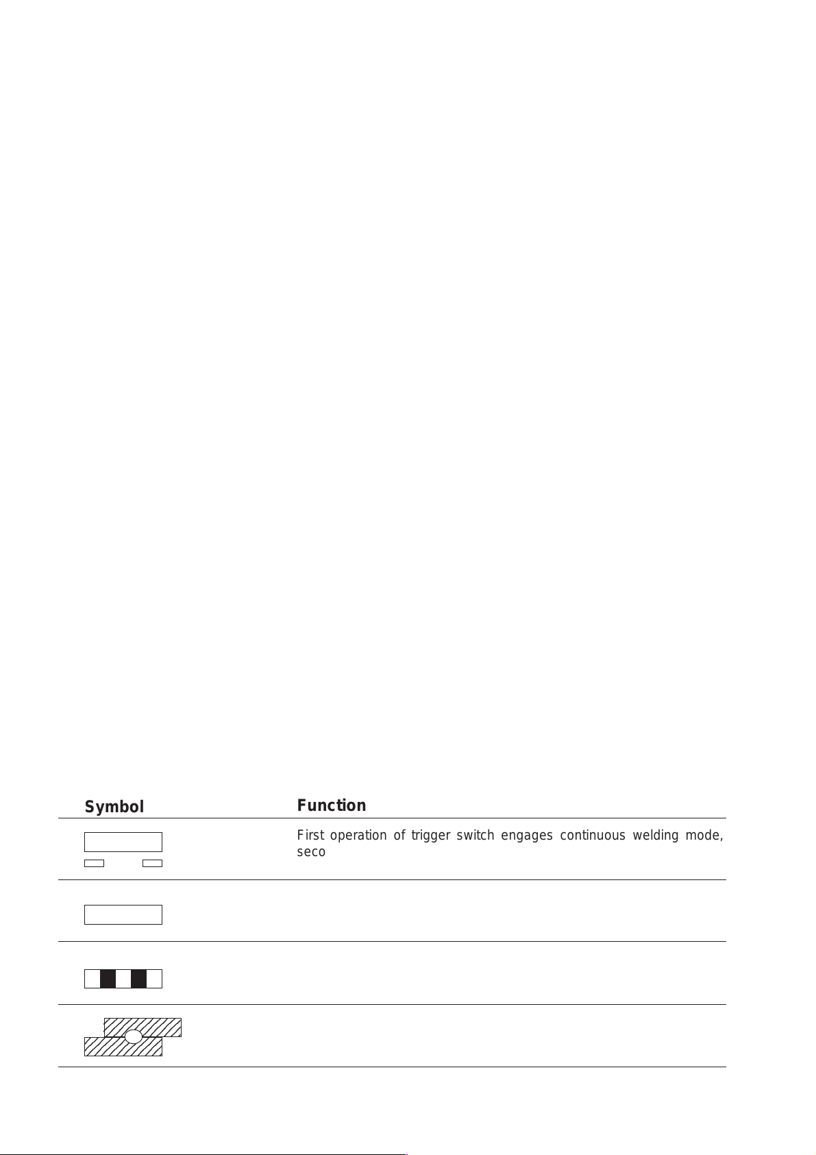
Welding Mode Selector (no. 6)
Symbol
Function
First operation of trigger switch engages continuous welding mode,
second operation disengages
Machines operates as long as trigger switch
is held
Stitch-weld mode
2345678901
2345678901
2345678901
Spot-weld mode
Setting of stitch and spot weld periods by potentiometers (nos. 8 + 9)
t1 = setting of weld time
t2 = setting of dwell time
Page 10

6 Practical Hints for MIG Welding
This distance required between the torch and the workpiece is directly related to the welding current:
● small current = small distance
● high current = greater distance
Too little distance causes excessive wear of the contact tip and gas shroud. Too much distance will not provide
enough gas protection of the welding seam, it becomes porous.
Move the welding gun along the seam in a steady motion, always keeping the same distance between the torch
and workpiece.
Welding may be done either forehand or backhand, in a straight line or, with larger gaps, in a pendulum motion.
MIG welding is suitable for thin plate welding, as well as for welding thicker materials of up to 12 mm.
For thin plate welding we recommend the use of electrode wire of 0.6 mm diameter and a mixed shielding gas.
Welding Preparations
Attach earth clamp to work piece as close as possible to the welding seam (remove rust, paint etc. to ensure good
conducting). Set welding current and wire feed speed with welding step selector and wire feed speed regulator as
required. Make trial runs on scrap material to find correct setting.
6.1 Earth Cable
Connect earth cable plug to Earth Cable Socket on the machine's front panel. Use only genuine Elektra Beckum
parts with recommended cross sections. Structural components, beams, pipes or rails should not be used for earth
conducting, if they are not the actual workpiece. When using welding tables or jigs ensure proper conducting.
6.2 Gas Flow Setting
The correct amount of shielding gas and a steady gas flow at the welding seam are essential to provide sufficient
shielding of the weld pool. Insufficient shielding causes porous welding seams.
Rule of thumb to calculate the shielding gas flow rate required:
Amount of gas in ltr/min = 10 x the electrode wire diameter in mm
Example: Wire diameter 1.0 mm requires a gas flow rate of 10 ltr/min.
Diagram showing the exact gas flow rate required, accounting for different welding current settings
Gas flow rate
in ltr/min
Steel
Gas shroud
diameter in mm
Welding current in A
7 Maintenance
The contact tip and gas shroud are the parts most exposed to the radiant heat of the arc and thus are normal
wearing parts. They have to be cleaned regularly of spatters and sprayed with anti-clogging spray.
Execessive built-up of spatters can short-circuit contact tip and gas shroud, ruining both. Spatter built-up inside
the gas shroud also affects the gas flow to the welding seam.
The machine has to be checked in regular intervals for visible damages.
Dust built-up inside the machine can reduce the duty cycle considerably and may even cause a short circuit. Check
regularly and clean if necessary.
Before removing side panel be sure that machine is disconnected from power supply to prevent injury from electric
shock.
Page 11

8 Trouble Shooting
Fault
Irregular wire feed Incorrect tension of tension roller
Brittle or porous welding
seam
Constant gas flow Solenoid valve defective or dirty Check, clean or replace
No wire feed Trigger switch or leads in lead ass'y defective
Cause Remedy
Adjust tension
Pilot groove of feed roller and intake nozzle not
aligned
Liner clogged or not correct size for wire
Wire spooled irregularly, rusty or of inferior quality
Wire spool carrier to tight
Feed rollers dirty of worn, groove not matching
wire size
Gas line fittings not tight
Gas cylinder empty
Gas cylinder valve closed
Pressure regulator not working
Solenoid valve not working
Gas shroud or line in lead ass'y clooged
Air draft at weld seam
Workpiece not clean
Wire of inferior quality or unsuitable gas
PCB defective
Fine wire fuse on PCB defective
Align
Check and/or change
Clean or change liner
Change spool
Loosen
Clean or replace
Check fittings
Replace cylinder
Open valve
Check
Check power at solenoid
Clean shroud and spray, blow out gas line
Protect from draft or increase gas flow
Remove rust, grease, paint
Change wire, use suitable gas
Check, replace if necessary
Replace
Replace (2 amp time-lag)
Wire feed speed not
adjustable
Not welding current with
normal working wire feed
Arcing when gas shroud
touches workpiece
Torch becomes excessively hot
No function of machine
Torch under current when
machine is switched OFF
3-phase machine:
excessive spattering with
all welding step setting
3-phase machine:
excessive spattering at a
particular welding step
PCB defective Replace
Contactor faulty
Step with faulty
Earth cable not conducting
Short-circuit between contact tip and gas shroud Clean shroud, treat with anti-clogging spray or
Contact tip loose or too large for wire diameter Tighten tip; replace with correct size tip
Mains fuse/circuit breaker tripped
Contactor sticky or contacts burned
One phase missing Check contactor for proper function
Step switch defective
Cables between step switch and transformer
loose or broken
Replace
Replace
Correct
nozzle dip (see footnote below).
Reset or replace
Check and replace
Check mains fuses, check power at contactor
terminals (all 3 phases)
Check and replace
Check and replace
Important!
The capacitors of the 1-phase machines need 40 seconds to discharge completely after the machine
is switched off. If the electrode wire makes contact with the workpiece during this period, a short
discharge spark is generated.
Page 12

9 Spare Parts List and Accessories
Description Stock-no. Combi Combi
Rectifier bank 805 307 5313 x x
Rectifier bank 805 307 0850 x
Rectifier bank 805 307 1717 x
Rectifier bank 805 307 1725 x
Rotary fan 804 106 5703 x x x x x
Central coupling 132 703 3430 x x x x x
6-step selector switch 811 507 1336 x x x
6-step selector switch 811 507 2901 x x
Switch on/off with pilot light 811 105 9692 x x x
Neon pilot Light 380 V yellow 860 112 1000 x x x
Neon pilot Light 380 V white 860 112 1019 x x
Selector switch 811 208 5620 x x
Capacitor bank 44.000 µF 100 200 2252 x x
Capacitor bank 66.000 µF 100 200 4808 x
Contactor B 6-30-10 810 407 3825 x x x x
Contactor B 9-40-00 810 403 8140 x
PCB standard 16 A relay 810 660 0695 x x
PCB electronic 16 A 810 600 7390 x x x
Board "making current limiter" 810 662 8506 x x x
Fine-wire fuse 2 A 826 010 6814 x x x
DINSE socket 25 mm 821 507 1309 x x x x
DINSE socket 50 mm 821 507 1317 x
DINSE plug 50 mm 821 503 7895 x
DINSE plug 25 mm 821 503 7887 x x x x
Earth clamp 200 A 090 200 1220 x x x x
Earth clamp 300 A 090 200 1239 x
Power cord 840 209 4428 x
Power cord 840 212 7911 x x
Power cord Combi 840 212 7938 x x
Adaptor Combi 1-ph/2-ph 100 200 4956 x x
Magnetic valve 805 205 2433 x x x x x
Spool carrier 132 107 3880 x x x x x
Wire feed motor 24 V 801 113 0047 x x x x x
Feed roller Ø 30 132 515 4795 x x x x x
Grooved ball bearning 710 001 0180 x x x x x
Pressure spring 705 108 6532 x x x x x
Spring guide 132 508 5840 x x x x x
Steel liner 140 mm 132 707 1129 x x x x x
Knotted link chain 723 607 0870 x x x x x
Pressure regulator dual clock 090 200 5285 x x x x x
Welding visor 090 200 1255 x x x x x
Panel connector 9-pin 100 201 4080 x x x
Wire Harness with 9-pin plug 845 007 2231 x x x
170/30 170/30 180/35 200/35 230/40
TL TL ET ET ET
Accessories Stock-no.
Anti-clogging spray 132 703 8296
2-row wire brush 090 202 7823
Nozzle pliers 090 202 7483
Adaptor for basket reel K 300, 2-tlg. 090 201 2630
Dual gauge pressure regulator 090 203 1472
Electrode Wire
SG-2-Ø 0.6 mm (1 roll = 5.0 kg) 441 106 0905
SG-2-Ø 0.8 mm (1 roll = 5.0 kg) 441 106 0921
SG-2-Ø 0.6 mm (1 roll = 15.0 kg) 441 106 0913
SG-2-Ø 0.8 mm (1 roll = 15.0 kg) 441 106 0930
SG-2-Ø 1.0 mm (1 roll = 15.0 kg) 441 106 0948
SG-2-Ø 1.2 mm (1 roll = 15.0 kg) 441 106 0956
SG-2-Ø 0.6 mm (1 basket = 15.0 kg) 441 115 4721
SG-2-Ø 0.8 mm (1 basket = 15.0 kg) 441 114 1549
SG-2-Ø 1.0 mm (1 basket = 15.0 kg) 441 114 1557
SG-2-Ø 1.2 mm (1 basket = 15.0 kg) 441 115 4730
Alu Ø 0.8 mm (1 roll = 2.0 kg) 441 101 4555
Alu Ø 1.0 mm (1 roll = 6.0 kg) 441 100 3600
Page 13

MIG Welding Torch SB 14/3
For models: MIG/MAG 170/30 TL
MIG/MAG 170/30 TL Combi
Pos. Description Order No.
Welding torch SB 14/2 cpl.
with torch leads 3 m 090 200 9914
10 Swan neck cpl. 090 202 7378
12 Nozzle spring (5x) 090 202 7670
13 Head insulator 132 704 5241
15 Swan neck boot 132 706 1093
20 Handle red cpl. 132 704 5101
21 Trigger red 2-pol. 132 707 4772
30 Cable support 132 704 5209
41 Lock nut M10x1 132 704 5110
60 Cable support 132 706 4068
61 Adaptor nut 132 706 4076
Pos. Description Order No.
63 KZ2 adaptor block 132 707 5515
64 Liner positioner nut M10x1 132 706 4106
65 O-ring 132 706 4092
66 Trigger wire connector, fermale 132 706 4084
100 Contact tip ECU M6 - 0.6 mm (5x) 090 202 7645
100 Contact tip ECU M6 - 0.8 mm (5x) 090 202 7653
130 Gas nozzle, con. (3x) 090 202 7742
131 Gas nozzle, cyl. (3x) 090 202 7750
132 Gas nozzle, con. small 132 704 5365
133 Gas nozzle, tapered 132 704 5373
134 Gas nozzle Nagelanschw. (1x/1x) 090 202 7769
134 Gas nozzle 132 704 5381
150 PE-liner with liner positioner 132 704 5195
Page 14

MIG Welding Torch SB 15/3; SB 15/4; SB 15/5
For models: MIG/MAG 180/35 ET Combi
MIG/MAG 200/35 ET
Pos. Description Order No.
Welding torch SB 15/2 3 090 200 9949
Welding torch SB 15/2 4 090 200 9957
Welding torch SB 15/2 5 090 200 9965
10 Swan neck 090 202 7386
12 Nozzle spring (5x) 090 202 7670
13 Head insulator 132 704 5241
14 Swan neck spacer 132 704 5276
15 Swan neck boot 132 704 5233
16 Torch body, plastic 132 707 4527
16 Torch body, brass 132 707 4519
20 Handle, red cpl. 132 706 4319
30 Cable support 132 704 5209
41 Lock nut 132 704 5268
60 Cable support 132 706 4068
61 Adaptor nut 132 706 4076
63 KZ2 adaptor block 132 707 5515
64 Liner positioner nut 132 706 4106
65 O-ring 132 706 4092
66 Trigger wire connector, fermale 132 706 4084
Pos. Description Order No.
100 Contact tip ECU M6 - 0.6 mm (5x) 090 202 7645
100 Contact tip ECU M6 - 0.8 mm (5x) 090 202 7653
100 Contact tip ECU M6 - 1.0 mm (5x) 090 202 7669
100 Contact tip ECU M6 - 1.2 mm 132 705 6693
130 Gas nozzle, conical (3x) 090 202 7742
131 Gas nozzle, cylindrical (3x) 090 202 7750
132 Gas nozzle, conical small 132 704 5365
133 Gas nozzle, tapered 132 704 5373
134 Gas nozzle, studweld 8 (1x/1x) 090 200 1433
134 Gas nozzle 132 704 5381
140 Insulated liner 0.6 - 0.9 3 m 132 706 4203
140 Insulated liner 0.6 - 0.9 4 m 132 706 4211
140 Insulated liner 0.6 - 0.9 5 m 132 706 4220
140 Insulated liner 1.0 - 1.2 3 m 132 706 4238
140 Insulated liner 1.0 - 1.2 4 m 132 706 4246
140 Insulated liner 1.0 - 1.2 5 m 132 706 4254
150 Polyamid liner 0.8 - 1.2 3 m 132 714 4550
150 Polyamid liner 0.8 - 1.2 4 m 132 714 4541
150 Polyamid liner 0.8 - 1.2 5 m 132 714 4533
152 Guide tube for polyamid liner 132 704 5578
153 O-ring 132 707 5531
Page 15

MIG Welding Torch SB 25/2
For models: MIG/MAG 230/40 ET
Pos. Description Stock-No.
Welding Torch SB 25/2
with torch leads 3 mtr 090 200 8330
with torch leads 4 mtr 090 200 8349
with torch leads 5 mtr 090 200 8357
10 Swan neck, complete 090 202 7416
12 Gas shroud spring 132 704 5454
16 Torch body, plastic 132 707 4527
20 Handle ass'y, red SB 25-SB 501 132 706 4319
30 Lead support 132 704 5209
60 Lead support 132 706 4068
61 Adaptor nut 132 706 4076
63 Central adaptor block KZ2 132 707 5515
64 Collte nut M 10x1 132 706 4106
65 O-ring 4x1 132 706 4092
66 Trigger lead connector 132 706 4084
100 Contact tip M6 - 0.8 mm 132 704 5462
100 Contact tip M6 - 1.0 mm 132 704 5489
100 Contact tip M6 - 1.2 mm 132 704 5497
100 Contact tip M6 - 0.8 mm Aluminium 132 700 9695
Pos. Description Stock-No.
100 Contact tip M6 - 1.0 mm Aluminium 132 700 9709
100 Contact tip M6 - 1.2 mm Aluminium 132 700 9717
110 Contact tip holder 132 707 5574
130 Gas shroud, conical 132 704 5519
131 Gas shroud, cylindrical 132 704 5500
132 Gas shroud, conical small 132 704 5527
133 Gas shroud, bottle neck 132 704 5535
134 Spot weld shroud 132 704 5543
140 Insulated liner, blue, 0.6-0.9 3 mtr 132 706 4203
140 Insulated liner, blue, 0.6-0.9 4 mtr 132 706 4211
140 Insulated liner, blue, 0.6-0.9 5 mtr 132 706 4220
140 Insulated liner, red, 1.0-1.2 3 mtr 132 706 4238
140 Insulated liner, red, 1.0-1.2 4 mtr 132 706 4246
140 Insulated liner, red, 1.0-1.2 5 mtr 132 706 4254
150 Polyamid liner, 0.8 - 1.2 3 mtr 132 714 4550
150 Polyamid liner, 0.8 - 1.2 4 mtr 132 714 4541
150 Polyamid liner, 0.8 - 1.2 5 mtr 132 714 4533
152 Guide tube polyamid liner 4.0 OD 132 704 5578
153 O-ring 3.5x1.5 for guide tube 132 707 5531
Contact tip wrench (not shown) 132 704 5411
Page 16

D DEUTSCH ENG ENGLISH
Ñ
Ê
ÖRSÄ
KONFORMITÄTSERKLÄRUNG DECLARATION OF CONFORMITY
Wir erklären in alleiniger Verantwortlichkeit, daß dieses Produkt mit den
folgenden Normen übereinstimmt* gemäß den Bestimmungen der
Richtlinien**.
F FRANÇAIS NL NEDERLANDS
DECLARATION DE CONFORMITE CONFORMITEITSVERKLARING
Nous déclarons, sous notre seule responsabilité, que ce produit est en
conformité avec les normes ou documents normatifs suivants* en vertu des
dispositions des directives **
IT ITALIANO ES ESPA
DICHIARAZIONE DI CONFORMITÀ DECLARACION DE CONFORMIDAD
Noi dichiariamo sotto la nostra esclusiva responsabilità che il presente
prodotto è conforme alle seguenti norme*. in conformità con le disposizioni
delle normative **
PT PORTUGU
DECLARAÇÃO DE CONFORMIDADE
Declaramos sob nossa responsabilidade que este produto está de acordo
com as seguintes normas*.de acordo com as directrizes dos regulamentos
**
FIN SUOMI NO NORGE
VAATIMUKSENMUKAISUUSVAKUUTUS SAMSVARSERKLÆRING
Vakuutamme, että tämä tuote vastaa seuraavia normeja*.on direktiivien
määräysten mukainen**
S SV SVENSKA
We herewith declare in our sole responsibility that this product complies with
the following standards*
in accordance with the regulations of the undermentioned Directives**
Wij verklaren als enige verantwoordelijke, dat dit product in overeenstemming
is met de volgende normen*
conform de bepalingen van de richtlijnen**
OL
Declaramos bajo nuestra exclusiva responsabilidad, que el presente producto
cumple con las siguientes normas*.de acuerdo a lo dispuesto en las
directrices**
F
KRAN OM ÖVERENSSTÄMMELSE
Vi försäkrar på eget ansvar att denna produkt överensstämmer med följande
standarder*. Enligt bestämmelserna i direktiven**
Vi erklærer under eget ansvar at dette produkt samsvarer med følgende
normer*. henhold til bestemmelsene i direktiv**
DA DANSK POL POLSKI
OVERENSSTEMMELSESATTEST OŚWIADCZENIE O ZGODNOŚCI
Hermed erklærer vi på eget ansvar, at dette produkt stemmer overens ed
følgende standarder*. iht. bestemmelserne i direktiverne**
EL ΕΛΛHNIKA HU MAGYAR
∆ΗΛΩΣΗ ΑΝΤΙΣΤΟΙΧΕΙΑΣ MEGEGYEZŐSÉGI NYILATKOZAT
∆ηλώνουµε µε ιδία ευθύνη ότι το προϊόν αυτό αντιστοιχεί στις ακόλουθες
προδιαγραφές* σύµφωνα µε τις διατάξεις των οδηγιών**
Oświadczamy z pełną odpowiedzialnością, że niniejszy produkt odpowiada
wymogom następujących norm*.według ustaleń wytycznych **
Kizárólagos felelősségünk tudatában ezennel igazoljuk, hogy ez a termék
kielégíti az alábbi szabványokban lefektetett követelményeket*.megfelel az
alábbi irányelvek előírásainak**
MIG/MAG 170/30 TL - MIG/MAG 170/30 TLC
MIG/MAG 180/35 ETC - MIG/MAG 200/35 ET - MIG MAG 230/40 ET
*EN 60974-1, EN 50199, DIN EN 55104: 12.1995
** 98/37/EG - 89/336/EWG - 73/23/EWG
Ing. grad. Hans-Joachim Schaller
Leiter Entwicklung und Konstruktion
Metabowerke GmbH
Business Unit Elektra Beckum
Daimlerstr. 1
D - 49716 Meppen
D - 49716 Meppen, 10.02.2003 1001106
Page 17

Apartado 53; 7000-171 Evora Codex; (+351) 266 - 74 93 00; (+351) 266 - 74 93 09;
bolas@mail.telepac.pt
Portugal; BOLAS-Maq. e Ferramentas de Qualidade, S.A.; Rua B, Lotes 8-10-12;
Puerto Rico; J.J. Trading; PMB 409 P.O. Box 4956 Caguas; ; Puerto Rico 00726-4956;
AJAC
(+1) 787 - 739 9693; (+1) 787 - 739 1177; jochi@coqui.net
ganesh@gulfincon.com
Zona 9-A; Panamá; (+507) 2 23 77 05; (+507) 2 69 18 66; germante@cableonda.net
STREET; MEADOWDALE - Germiston; Johannesburg; (+27) 11 - 372 - 96 00;
(+27) 11 - 453-41 63; ebotha@metabo.co.za
Domingo; (+1) 809 - 531 50 80; (+1) 809 - 531 53 38;
jgarcia@agroindustrialferretera.com
(+40) 1 - 3 46 31 31; (+40) 1 - 3 46 31 51; agent@dial.kappa.ro
(+7) 095 - 198 43 14/198 17 13; (+7) 095 - 198 43 14; metabo_service@mail.ru
(+41 ) 52 - 3 54 34 44; (+41) 52 - 3 54 34 45; service@metabo.ch
(+22) 1 - 823.67.14; (+22) 1 - 823.67.14;
Number One Building; Singapore 408563; (+65) 67 48 28 66; (+65) 67 45 38 72;
sales@homely.com.sg
(+421) 33 - 641 2522; (+421) 704 - 6 41 25 22; metabo@stamet.sk
(+386) 61 - 1 68 16 16; metabo@dilex.si
263-1 Ipchung-Dong, Chung-Gu; Seoul; (+82) 2 - 22 76 09 14/5; (+82) 2 - 2 78 62 62;
kwlee@metabokorea.co.kr
P.O. Box 214 / 130 Front Street; Colombo 11; (+94) 1 - 2 81 71 / 72 / 73;
(+94) 1 - 50 11 83; hunters@eureka.lk
Santa Lucia; (+1)758 - 452-99 14; (+1)758 - 452-99 15; eurotools@candw.Lc
P.O. Box 169 / Code 113; ; Muscat; (+968) 7 71 09 83; (+968) 7 71 57 55;
ssbbm@omantel.net.om
(+46) 36 - 16 07 54; mwidell@metabo.dk
(+963) 21 - 2 11 62 45; taoutelco@net.sy
(+886) 2 - 28 11 08 08; (+886) 2 - 28 16 98 38; t900530@ms9.tisnet.net.tw
Pomprab Bangkok 10100; (+66) 2 - 3 28 11 89; (+66) 2 - 3 28 13 04; vinai@ssm.co.th
(+216) 1 - 25 83 92; (+216) 1 - 35 18 45; equipement-moderne@planet.tn
(+90) 212 - 2 56 49 50; (+90) 212 - 2 38 98 26; elalet@burla.com
03 151 Kiev; (+380) 44 - 2 45 94 34; (+380) 44 - 2 45 96 57; comserv@ukrnet.net
(+971) 6 - 533 05 51 ; (+971) 6 - 533 73 68; sedana@emirates.net.ae
Brandywine Industrial Park; West Chester, PA 19380; (+1) 610 - 4 36 59 00;
(+1) 610 - 4 36 90 72; info@metabousa.com
(+598) 2 - 92 26 06; (+598) 2 - 92 12 69; goldfarb@montevideo.com.uy
Caracas 1071; (+58) 212 - 2 37 30 22; (+58) 212 - 2 39 23 65;
masmuss@olycopia.com
Tan Binh District; Ho Chi Minh City; (+84) 8 - 811 74 54; (+84) 8 - 811 63 38;
TVTLinh@hcm.fpt.vn
(+38) 12 15 28 56; (+38) 12 15 24 57; woby@Eunet.yu
Qatar; Gulf Incon; P.O.Box 4076; ; Doha; (+974) 4 68 35 11; (+974) 4 68 40 65;
Rep. de Panamá; German-Tec (Panamá) S.A.; Via Argentina 46-70; Apartado 342,
Republic of South Africa; Metabo Power Tools SA (Pty.) Ltd.; 165 Van DER BIJL
Republica Dominicana; Agroindustrial Ferretera S.A.; Av. Luperon No. 42; ; Santo
Rumania; S.C. Agent Trade S.R.L.; Splaiul Unirii 235-237; ; 74299 Bucuresti 3;
Russia; OOO ITA-Strojinkom; Uliza Alabjana 3; ; 125057 Moskau;
Schweiz; Metabo (Schweiz) AG; Lindauerstr. 17; ; 8317 Tagelswangen;
Senegal; Ets. M.Y.S.; 12, Rue Tolbiac; B. P. 2389; Dakar;
Singapore; HOMELY HARDWARE PTE LTD; No. 1 Ubi Crescent #01-01;
Slovakia; STAMET Bratislava spol. s.r.o.; M.R. Stefanika 28; ; 90201 Pezinok;
Slovenia; Dilex d.o.o.; Ogrinceva 17; ; 1000 Ljubljana; (+386) 61 - 1 68 16 20;
South Corea; Metabo-Korea Co. Ltd.; Room No. 101, Daesung Building;
Sri Lanka; Hunter + Company Ltd.; General Hardware Importers ;
St. Lucia; Eurotools Int`l Ltd; P.O.Box RB 2484; Rodney Bay, Gros Islet, West Indies;
Sultanate of Oman; Suhail & Saud Bahwan Building Materials L.L.C.;
Sverige; Metabo Sverige AB; Skiffervägen 6; ; 553 03 Jönköping; (+46) 36 - 10 06 60;
Syria; Bachar & Elias Taoutel; Boite Postal 325; ; Aleppo; (+963) 21 - 2 11 80 30;
Taiwan; Taiwan Overseas Trade Co. Ltd.; No. 103 Chung King N. Road Sec. 4; ; Taipei;
Thailand; SSM - Sri Siam Mongkol Co., Ltd; 1570-1576 Krung Kasem RD.; ;
Tunesia; L´Equipment Moderne; 86, Ave. de Carthage; ; 1000 Tunis;
Turkey; Burla A.S.; Voyvoda Cad. 61-65; ; 80003 Karaköy-Istanbul;
Ukraine; Comservice; Ukraian-Russian Joint Venture 2; Narodnogo Opolcheniaya;
United Arab Emirates; Sedana Trading Co; P.O. Box 1919; ; Sharjah;
United States of America; Metabo Corporation; 1231 Wilson Drive / P.O.Box 2287;
Uruguay; Goldfarb S. A.; Rio Negro 1617; P.O. Box 11100; Montevideo;
Venezuela; OLY-COPIA C.A.; 3 ra Transversal Los Ruices ; Edificio Principal II, Piso 4;
Vietnam; HUU HONG MACHINERY CO., LTD.; 157-159 Xuan Hong Street, Ward 12;
(+263) 4 - 77 52 56-9; (+263) 4 - 77 06 95; costa@field.icon.co.zw
Yugoslavia; WHM WOBY HAUS MARKT; Brace Ribnikara 55; ; 21000 Novi Sad;
Zimbabwe; Field Technical Sales; 45 Kelvin Road North; Graniteside; Harare;
Ambethan Road, Kharabwadi; Chakan, Tal.: Khed, Dist.-Pune(Pin410 501);
India; Metabo Power Tools PVT Ltd.; Plot No. 40, WMDC Industrial Complex;
Country; Company; Address 1; Address 2; City; Phone; Fax; E-mail
Albania; Extra Industrial Goods; Rl. Fadil Rada 88; ; Tirana; (+355) 42 - 3 30 62;
(+91) 213 - 55 22 03; (+91) 213 - 55 21 61
Indonesia; P.T. Kawan Lama Sejahtera pt; Gedung Kawan Lama Jl. Puri Kencana No. 1;
(+355) 42 - 3 30 62; abeqiri@t-online.de
Algerie; Haddad Equipement Professionel; 98 A, Site du Lycée; ; 16012 Rouiba;
Meruya - Kembangan; Jakarta 11610; (+62) 21 - 5 82 82 82;
(+213) 21 - 85 49 05; (+213) 21 - 85 57 72; heprouiba@hotmail.com
(+62) 21 - 5 82 55 88; kawanlama@kawanlama.com
Argentina; Metabo Argentia S.A.; Teniente Gral. Richieri 4773; ; 1702 - Ciudadela -
Iran; Kalavaran Co. Ltd.; P.O.Box: 11365 - 4653; ; Tehran;
Buenos Aires; (+54) 11 - 44 88 - 9180; (+54) 11 - 44 88 - 39 89; info@metabo.com.ar
(+98)21 - 67 00 862/67 01 383; (+98)21 - 67 09 427; kalavaran@kalavaran.com
Australia; Metabo Pty. Ltd; 10 Dalmore Drive; ; Scoresby, Melbourne, Vic. 3179;
Israel; Proter + Cohn Ltd; Technical Supply P.O.Box 33215 / 3; Haatzmaut Road;
(+61) 3 - 97 65 01 99; (+61) 3 - 97 65 01 89; sales@metabo.com.au
33033 Haifa; (+972) 4 - 8 64 04 69; (+972) 4 - 8 67 18 03; dubovsky@matav.net.il
Italia; Carlo Stechel & Figli S.rl; Via Buozzi, 22; ; 20 097 San Donato Milanese (MI);
P.O. Box 5262; Manama; (+973) 71 36 15 / 71 41 74; (+973) 71 26 12;
Bahrain; Bokhammas Establishment; Bldg. 334 Block 321 Old Exhibition Road;
(+39) 02 - 52 77 71; (+39) 02 - 55 60 03 22; cstechel@stechel.it
Japan; Metabo Japan Co., Ltd.; 5-1024-3, Baigou, Ohme-city; ; Tokyo 198-0063;
bokhamas@batelco.com.bh
Bangladesh; East Bengal Impex; 175, Nawabpur Road (4th floor); ; Dhaka; ;
(+81) 4 - 28 77 05 06; (+81) 4 - 28 77 05 07
Jordan; Newport Trading Agency; P.O.Box 6166 / 151 Hashimi Str.; City Center;
(+880) 2 - 9 56 94 77 / 9 55 04 00;
Belarus; Rosinstrument LTD. INTL. DEPT.; PR-T Skkoriny 107-11; P.O.Box 67; 220023
Amman 111 18; (+962) 6 - 465 56 80; (+962) 6 - 464 54 39; jsakkab@nta.com.jo
Minsk; (+375) 17 263 99 94; (+375) 17 263 99 94; metabo@rosinstrument.com
Kenya; Agriquip Agencies (E.A.) Ltd.; Lusaka Rd.; P.O.Box 30 612; Nairobi;
Belgique; Metabo Belgium; ´t Hofveld 3 - 5; ; 1702 Groot Bijgaarden;
(+254) 2 - 54 02 70 / - 73; (+254) 2 - 54 00 56; pravack@wananchi.com
Kingdom of Saudi Arabia; Saudi Industrial Tools Corporation; Madinah Road, Kilo 9;
(+32) 2 - 4 67 32 10; (+32) 2 - 4 66 75 28; general@metabo.be
Bolivia; Agencias Generales S.A.; Casilla de Correo 530 Avda. San Martin S-0253; ;
P.O.Box 11429; Jeddah 21453; (+96) 62 - 6 82 04 58; (+96) 62 - 6 91 12 67;
Cochabamba; (+591) 4 - 425 10 62 ; (+591) 4 - 425 10 61; agsa@supernet.com.bo
sitaco@sitaco.com.sa
Bosnia and Herzegovina; Agrarkombinat; Majevicka 1; ; Banja Luka;
Kuwait; Naser Moh. Al-Sayer ; Gen. Trading & Contracting Co.; P.O. Box 663 SAFAT;
(+387) 51 - 302 718; (+387) 51 - 785 708; agrokombinat@blic.net
13007 State of Kuwait; (+965) 47 47 137; (+965) 47 47 945;
Brazil; Metabo do Brasil Ltda.; Rua Guicurus 306 - Vila Conceicao; ;
Alsayer_electro@hotmail.com
Diadema - Sao Paulo - Cep 09911-630; (+55) 11 - 40 51 - 25 11;
Latvia; SIA WESS Instrumenti un Tehnika Ltd.; Ganibu dambis 34 a; ; 1005, Riga;
(+55) 11 - 4056 - 4152; metabo@metabo.com.br
(+371) 7 38 23 53; (+371) 7 34 94 72; imants.wessinst@apollo.lv
Latvia; Stoller Sia; Krasta 42; ; 1003, Riga; (+371) 7 24 55 61;
(+359) 2 - 9 78 58 90; (+359) 2 - 9 78 86 04; service@kirov.net
Bulgariia; KIROV Ltd.; Gara Iskar; Porutschik-Nedeltscho-Bontschev-Str.10; 1582 Sofia;
(+371) 7 24 55 62; stoller@stoller.lv
Lebanon; SPAN s.a.r.l.; Tools & Equipment Division; P.O. Box 90 - 1218; Beirut;
Ontario, L4Z 1 W6; (+1) 905 - 755 06 08; (+1) 905 - 755 06 11; info@metabo.ca
Canada; Metabo Canada Inc.; 190 Britannia Road East; Unit No. 12; Mississauga,
(+961) 1- 888 288; (+961) 1 - 902 690; span2@cyberia.net.lb
Ceska Republica; Metabo s.r.o; Kralovicka 544; ; 250 01 Brandys nad Labem;
Lithuania; Technikonas; Savanoriu 286; ; 3042 Kaunas; (+370) 37 - 31 15 53;
(+420) 202 - 80 44 55; (+420) 202 - 80 44 56; mlanda@metabo.cz
(+370) 37 - 31 10 21; Robertas@technikonas.lt
Macedonia; MAKWELD D.O.O.; Ilindenska 138; ; 1000 Skopje; (+389) 2 - 363 180;
(+56) 2 - 6 99 04 85; empresa@nordchil.cl
Chile; Nordchil S.A.; San Diego 895; ; Santiago de Chile; (+56) 2 - 6 72 29 11;
(+389) 2 - 364 746; MAKWELD@mt.net.mk
Magyarorszag; INNOSERVICE-METABO Márkaszerviz Kft.; 1101 Bp. Köbányai út.
Bogota; (+57) 1 - 346 28 99; (+57) 1 - 346 29 16; allesch@compuserve.com
Colombia; EUROTOOLS Ltda.; Avenida Caracas No. 74-25; Edificio Ferricentros-4 Piso;
47./b.; ; 1475 Budapest; (+36) 12 - 60 67 12; (+36) 12 - 60 14 23;
Costa Rica; Capris S.A.; Frente la Imprenta Nacional, La Uruca; P.O. Box 7-2400;
innoservice@mail.datanet.hu
San José; (+506) 2 32 91 11; (+506) 2 32 93 53; webmaster@capris.co.cr
56100 Kuala Lumpur; (+60) 3 - 92002966 / 92003966; (+60) 3 - 92007599;
Malaysia; Finetools SDN BHD; No. 7 Jalan 1/92C; Batu 3 1/4 Jalan Cheras;
(+385) 1 - 24 06 000; info@crom-zagreb.hr
Croatia; CROM d.o.o.; Obrtnicka 2; ; 10000 Zagreb; (+385) 1 - 24 06 246;
finetools@pd.jaring.my
Malta; G + T Imports Limited; Metabo Shop, Birkirkara By-Pass; ; Iklin BZN 11;
1641 Lefkosia, Cyprus; (+357) 22 - 34 95 77; (+357) 22 - 34 93 94;
Cyprus; Med Marketing Ltd. (eurotools); P.O. Box 27017; 17, Digenis Akritas Ave;
(+356) 21 - 43 54 24; (+356) 21 - 41 73 58; gtimports@mail.global.net.mt
condam@spidernet.com.cy
(+222) 525 14 09; staf@staf.mr
Mauritanie; S.T.A.F; B.P.: 40246; ; Nouakchott; (+222) 525 33 85;
(+45) 43 - 31 34 01; scarstensen@metabo.dk
Danmark; Metabo Danmark A/S; Helgeshoj Allé 12; ; 2630 Tastrup; (+45) 43 - 31 34 00;
(+230) 2 10 74 57; dema@intnet.mu
Mauritius; Dema - Supplies Ltd.; 2A Deschartres Street; ; Port Louis; (+230) 2 12 64 05;
0180 - 3 00 04 16; 0180 - 300 04 17; tmueller@metabo.de
Deutschland; Metabowerke GmbH ; Walter-Rauch-Str. 1; ; 72622 Nuertingen;
Mexico; Uniservicio Ferretero S.A de C.V.; Matamoros No. 237 Col. la Joya ;
Ecuador; Maquinarias Henriquez C.A.; P.O.Box 09 - 01 - 43 61; ; Guayaquil;
Del. Talpan; C.P. 14090 México, D.F.; (+52) 5 - 555 737 233; (+52) 5 - 555 737 244;
(+593) 4 - 25 43 00; (+593) 4 - 25 49 39; mhca@impsat.net.ec
info@metabo.com.mx
Moldova; BRISAR-COM S.R.L.; str. Sciusev, 78; ; 2012 Chisinau; (+373) 2 - 22 24 50;
(+372) 620 11 12; mecro@mecro.ee
Eestlane; A/S MECRO; Peterburi tee 44; ; 11415 Tallinn; (+372) 620 11 11;
(+373) 2 - 27 77 87; Alexey@orest.mldnet.com
Morocco; Sté Yyes Rouger; 20 Bd. Ibn Tachfine; ; 20300 Casablanca;
(Cairo); (+20) 2 - 3 03 02 51 / 3 47 89 17; (+20) 2 - 3 02 58 96;
Egypt; Modern Machines + Materials Co.; 18 Geziret El Arab. St.; ; Mohandseen Giza
(+212) 2 31 25 06; (+212) 2 - 31 24 62
El Salvador; Metabo S.A. de C.V.; Colonia Santa Clara, Pasaje C No. 20;
Nederland; Metabo Nederland b.v.; Postbus 180; ; 3620 AD Breukelen;
Cuscatancingo; San Salvador; (+503) 2 - 38 47 65; (+503) 2 86 52 36;
(+31) 3462 - 6 42 44; (+31) 3462 - 6 35 54; verkoop@metabo.nl
metabo1@telesal.net
New Caledonia; Ets. Szemmelveisz; 3, Rue Fernand Forest; Boite Postale 668;
Espana; Herramientas Metabo S.A.; Polígono Ind. Prado del Espino; C/Forjadores, 12;
98845 Nouméa; (+687) 27 20 02; (+687) 27 30 94; szemmelveisz@canl.nc
New Zealand; Tooline Ltd.; 49 A Sonter Road; P.O. Box 797; Christchurch;
28660 Boadilla del Monte (Madrid); (+34) 91 - 6 32 47 40; (+34) 91 - 6 32 41 47;
wbuhrle@metabo.es
(+64) 3 - 36 55 931; (+64) 3 - 36 55 932; martin@tooline.co.nz
Nigeria; Mathani Brothers Ltd.; 60 Park View North Action; ; London W3 OPT;
(+251) 1- 52 68 19; (+251) 1-53 53 85; sutco@telecom.net.et
Ethiopia; SUTCO Pvt. Ltd. Co.; W. 19 K. 50 HN new, Wollo Sefer; ; Addis Ababa;
(+44) 20 - 8992 5727; (+44) 20 - 8992 5335; bestline@infoweb.abs.net
Finland; Wihuri Oy Autola; P.O. Box 58 Manttaalitie 9; ; 01511 Vantaa;
(+234) 1 - 774 1305; (+234) 1 - 774 1305; bestline@infoweb.abs.net
Nigeria; Bestline Nigeria Ltd.; 15, Hospital Road; Olodi Apapa; Lagos ;
(+358) 9 - 41 58 15; (+358) 9 - 41 58 22 07; mauri.rahkonen@autola.wihuri.fi
France; Metabo S.A.; Z.A.C. 2, Avenue des Ormeaux; ; 78180 Montigny-le-Bretonneux;
Norway; Metabo Norge AS; Postboks 1296; ; 3205 Sandefjord; (+47) 33 - 44 55 55;
(+33) 1 - 30 64 55 30; (+33) 1 - 30 44 37 68; Metabo.fr@wanadoo.fr
(+47) 33 - 44 55 50; psteingrimsen@metabo.no
Pakistan; Mercantile Company; Mercantile House 44-Brandreth Road; ; Lahore;
P.O. Box 1783; Accra; (+233) 21 - 66 39 94; (+233) 21 - 78 02 90;
Ghana; Emmnock Powercom Ltd.; Knutsford. Avenue opp. Morocco House;
(+92) 42 - 7 66 11 88/7 63 06 81; (+92) 42 - 7 66 45 89/7 63 45 95;
mrcanco@brain.net.pk
(+595) 981 - 43 15 13; (+595) 21 - 33 36 77; taguato@conexion.com.py
(+51) 14 - 4 22 86 31; (+51) 14 - 442 41 30; kaufmann@terra.com.pe
(+63) 2 - 3 63 01 59; (+63) 2 - 3 61 48 41; nancytanyu@speedsurf.pacific.net.ph
(+48) 91 - 5 78 11 95; (+48) 91 - 5 78 07 76; serwis@metabo.pl
Paraguai; Taguato S.A.; Avda.Gra.Santos No. 1948/Tte. Garay; ; Asuncion;
Peru; Sucesion Carlos Kaufmann; Juan de Arona 760, Of.102 ; ; San Isidro ;
Philippines; Mach Tools Inc.; 185 A & B del Monte Avenue; ; Manresa, Quezon City;
emmnockpowercom@hotmail.com
Southampton / SO 16 OYT; (+44) 2380 - 73 20 00; (+44) 2380 - 74 75 00;
info@metabo.co.uk
01009; (+502) 3 32 47 24; (+502) 3 32 47 81; almpalma@amigo.net.gt
Great Britain; Metabo (UK) Ltd.; 25 Majestic Road ; Nursling Industrial Estate;
Guatemala; Almacen la Palma S.A.; 2a Calle 4-38, Zona 9; ; Guatemala Ciudad,
Hellas; Fedon N. Economides + Co.; Prigiponison Street 27; ; 11363 Athens;
(+689) 41 24 00; ets-dieumegard@mail.pf
Polska; Metabo Polska Sp. z o.o.; Gdynska 28; ; 73-110 Stargard Szczecinski;
Polynésie francaise; Ets Dieumégard Import; BP 14 132 Arue; ; Tahiti; (+689) 42 32 38;
(+30) 1 - 8 21 60 83 / 8 84 29 66; (+30) 1 - 8 82 56 00; fedon@compulink.gr
Sha Wan Road; Kowloon / Hong Kong; (+852) 29 26 22 00; (+852) 28 82 19 78;
rileytam@mail.jebsen.com.hk
(+354) 57 57 605; fossberg@fossberg.is
Hong Kong; Jebsen & Co. Ltd. ; 9/F, Jebsen Motor Group Building; 924-926 Cheung
Iceland; Fossberg Ltd; Sudurlandsbraut 14; ; 108 Reykjavik; (+354) 57 57 600;
 Loading...