

Page 1
Manual
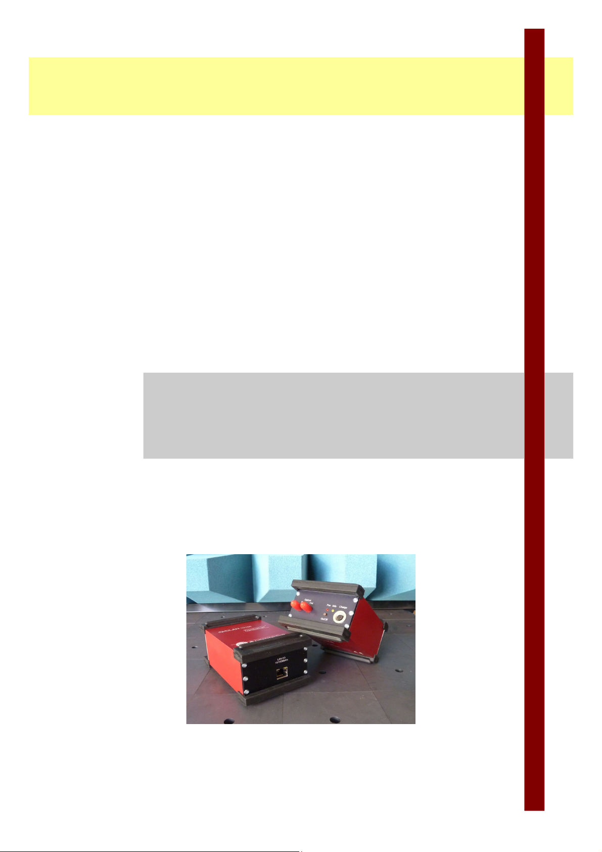
optoLAN
Digital optical transmitter
for Ethernet (10/100 Mbit) signals
Distributed by: Reliant EMC LLC, 3311 Lewis Ave, Signal Hill CA 90755, 4089165750, www.reliantemc.com
Page 2

Distributed by: Reliant EMC LLC, 3311 Lewis Ave, Signal Hill CA 90755, 4089165750, www.reliantemc.com
Page 3

Table of contents
1 Box contents....................................................................................................................... 4
2 Characteristics....................................................................................................................4
3 Field of application.............................................................................................................5
4 Maintenance....................................................................................................................... 5
5 Trouble shooting................................................................................................................. 7
6 Accessories / Options.........................................................................................................8
7 Contact............................................................................................................................... 8
Appendix: Details and operation.......................................................................................A1
Distributed by: Reliant EMC LLC, 3311 Lewis Ave, Signal Hill CA 90755, 4089165750, www.reliantemc.com
Page 4

Date:
11/15/11
optoLAN
Page: 4 Manual
1 Box contents
Quantity Description
2 Transceiver optoLAN
1 Duplex multimode optical fiber 62,5 / 125µm
2 Chargers (standard)
1 Manual (english)
2 External battery packs (optional)
The shipment includes charged batteries. However, due to the selfdischarging of NiMH-batteries they should be recharged again before use.
Read chap. 4 (Maintenance) before charging the devices!
2 Characteristics
The digital optical system optoLAN can be used to optically transmit
ethernet (10/100 Mbit) signals. Because of the optical transmission, the
system is very robust against EMS (electromagnetic susceptibility). It can
withstand high electric and magnetic fields, like they appear in EMC-tests.
The system also is optimized for low noise emission.
Power is supplied by internal NiMH-batteries which make the system easy
to use. The optoLAN is prepared for the use of external batteries (with
optional battery pack).
Read chap. 4 before
charging!
Distributed by: Reliant EMC LLC, 3311 Lewis Ave, Signal Hill CA 90755, 4089165750, www.reliantemc.com
Page 5

optoLAN
Date:
11/15/11
Manual Page 5
3 Field of application
• Transmission of ethernet signals up to 10/100Mbit/s during EMCtests
• Transmission of ethernet signals over long distances without signal
loss (up to 100m or more, depending on timing requirements)
• Handle ground potential problems
4 Maintenance
Recharge batteries after use with the enclosed charger. To prevent a lazy
battery effect, discharge the devices every 5 times completely by using the
automatic switch off (Leave the system on, until it turns off automatically).
Afterwards, charge the devices as usual.
The devices have to be turned off before connecting to the charger. If this
is disregarded, the system might get damaged!
Fig. 4.1 shows the pinning of the charge connector. Chargers have to be
connected to pin 2 (+) and pin 4 (GND). An external supply (6…8V, 0.5A)
can be connected to pin 3 (+) and pin 4 (GND). Use only power supplies
which are certified by mk-messtechnik.
Maximum charging
current is 1 A
Devices must be
turned off before
connecting to
charger, or else the
system might get
damaged!
Pinning of charge- /
buffer connector
Fig. 4.1: Pinning of charge- / buffer connector
Distributed by: Reliant EMC LLC, 3311 Lewis Ave, Signal Hill CA 90755, 4089165750, www.reliantemc.com
Page 6

Date:
11/15/11
optoLAN
Page: 6 Manual
The included chargers are not meant to power the transceivers during
operation. The transceiver outside the shielded room can be run with an
external power supply (optional). The internal transceiver can be run with
an external battery, if needed (optional). Do not use the external power
supply or charger to power the transceiver inside the shielded room while
EMI-tests are running. This might damage the transceiver!
Due to self-discharge issues with NiMH batteries, recharge batteries before
use, if the system has not been used for a longer time.
Do not use cleaning agents or solvents to clean the devices, only use a
slightly moistened, soft cloth.
Do not open the devices, as there are no parts inside which have to be
maintained. The opened housing can pose a fire hazard through shortcircuit currents! Please contact your distributor or the manufacturer if you
have any problems. Send in the complete system (both transceivers), if a
problem cannot be solved by turning the devices off and on again or by
checking the positions of the switches. Please contact us in any case
before sending in the devices.
Do not open the
devices!
Short cut / fire
hazard!
Do not use charger
or power supply
during EMI-test!
Distributed by: Reliant EMC LLC, 3311 Lewis Ave, Signal Hill CA 90755, 4089165750, www.reliantemc.com
Page 7

optoLAN
Date:
11/15/11
Manual Page 7
5 Trouble shooting
The following trouble shooting list is provided to assist you while having
problems. It might let you use the system again without a long down time:
Error: Possible reasons: Solution:
No or erroneous
transmission
Receiver does not
receive an optical signal
Cables damaged or not
attached properly
Wrong optical fibers
(diameter)
Low battery
System turned off
Check optical fibers and
connections, change
fibers if necessary
Connectors and cables
regarding damages
Use fiber with
62,5/125µm
Charge batteries
Turn on all devices
Transmission stops Low battery
No optical signal at
receiver
System turned off
Charge batteries
Check for light at optical
output. Replace optical
fiber
Turn on all devices
Device cannot be
turned on, cannot be
charged
Batteries damaged
Internal fuse is broke
Charger or cable
damaged
Batteries
over discharged
Send device to us
Send device to us
Check / replace charger
and charging cable
Charge batteries,
maybe use other
charger (5 battery cells)
Common problems Defective optical or
electrical cables or
connectors
Check connectors, fibers
and cables. Test with
other ones.
Replace cables
Distributed by: Reliant EMC LLC, 3311 Lewis Ave, Signal Hill CA 90755, 4089165750, www.reliantemc.com
Page 8

Date:
11/15/11
optoLAN
Page: 8 Manual
6 Accessories / Options
Part Order number Comment
Optical fiber LWL-2-xm x = length in m, duplex
External batteries BP-60 6V/4Ah
Connector cable for
BP-60
AK-BP Length approx. 15cm
Charger with
connector plugs CH-5 Standard charger
Manual MA-optoLAN German or english
Distributed by: Reliant EMC LLC, 3311 Lewis Ave, Signal Hill CA 90755, 4089165750, www.reliantemc.com
Page 9
optoLAN
Date:
11/15/11
Manual - Appendix Page A1
Appendix: Details and operation
The following chapter describes special details of the optoLAN system for
the transmission of ethernet signals. The system consists of two
transceivers.
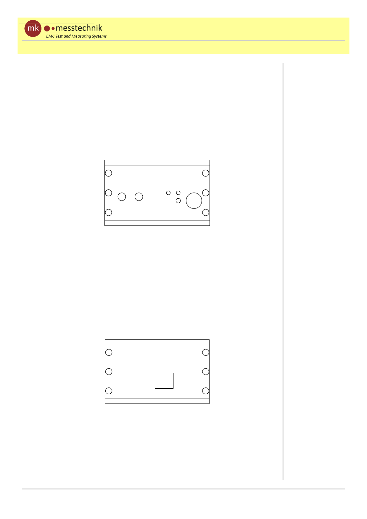
a) Housing and connectors / switches
Fig. a.1 shows the front side of the transceivers with connectors and
switches:
• power push button with control LED (Pwr On/Off)
• battery information LED (Info)
• charge plug (Charge)
• optical connector FSMA (Optical In .. Out) for duplex multimode
fiber (62,5/125µm)
Fig. a.2 shows the rear side of the transceivers with RJ45 connector.
(standard ethernet pinning):
• RJ45 plug LAN I/O 10/100Mbit/s for the ethernet signals to be
transmitted.
Front side with
connectors and push
buttons
Rear side with
connector. Pinning is
printed on the
housing too.
ChargePwrInfo
On/Off
Optical
In Out
LAN I/O
10/100Mbit/s
Fig. a.1: Front side of the devices with connectors and push buttons
Fig. a.2: Rear side of the devices with connectors and switches
Distributed by: Reliant EMC LLC, 3311 Lewis Ave, Signal Hill CA 90755, 4089165750, www.reliantemc.com
Page 10

Date:
11/15/11
optoLAN
Page: A2 Manual - Appendix
b) Operation and handling of the optoLAN
• Set up the devices at the dedicated places. The transceiver
connected to the PC can be powered by the power supply (optional)
all the time, if there is no need for battery supply (EMC issues). The
transceiver inside the chamber being connected to the DUT does
not have to be powered by a power supply during testing (might get
damaged)! It has integrated batteries to run the system.
• Connect the transceivers with standard ethernet cables (without
crossing) to the PC and the DUT. Inside the absorber lined chamber,
the ethernet cable should be as short as possible with a good
shielding (e.g. CAT 6 or higher) to avoid rf coupling into the system.
• Connect the optical fiber (Out => In; In => Out). Only use
62,5/125µm multimode fibers.
• Connect the electric cables
• Turn on all devices (power push button, see Fig. a.1); the order does
not matter
• The transmission starts automatically after a short initialization.
If the transmission suddenly stops after a long duration of measurement,
check the Info LED of the transmitter (see Fig. a.1).
If the battery power falls below 5,2V, the Info LED is switched on. The
system should be reloaded soon. Below 4,5V, the system is turned off
automatically.
The measurements can be extended by using the optional battery pack
(BP-60) with connector cable or a power supply certified by mkmesstechnik. The external supply can be connected to the system any time
(parallel). The connection to the internal battery is decoupled with a diode.
Only use the battery pack and connector cables from mk-messtechnik!
Others might lead to a damage of the system!
Check info LED if
transmission stops
suddenly!
Only use battery
packs and connector
cables provided
from mkmesstechnik. Other
modules influence
EMS-performance
and might damage
the opto-system!
The use of the
external filter is
essential for EMStests!
Use short, shielded
ethernet cables with
1:1 pinning!
(no crossing!)
Distributed by: Reliant EMC LLC, 3311 Lewis Ave, Signal Hill CA 90755, 4089165750, www.reliantemc.com
 Loading...