

Page 1
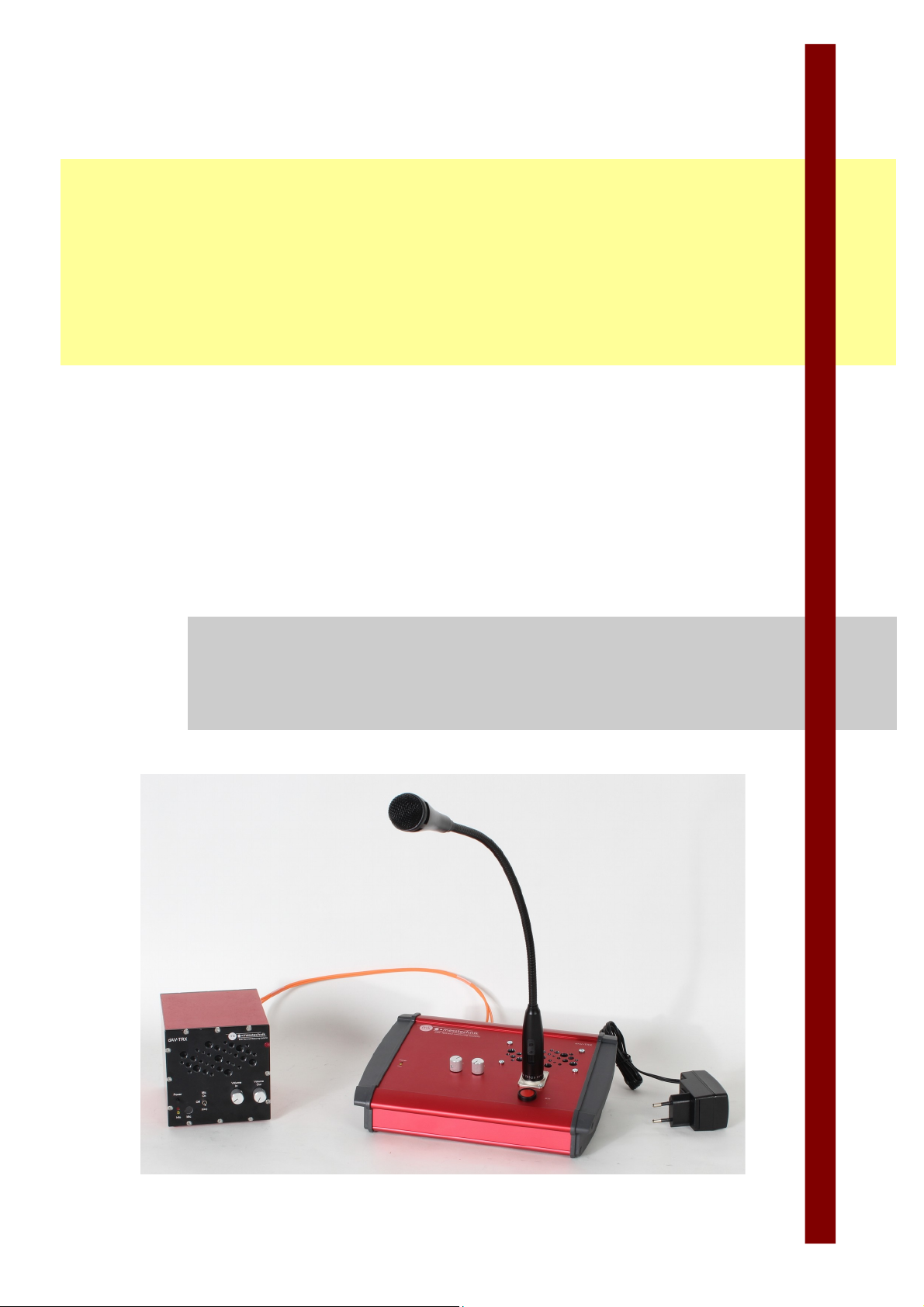
Intercom
dAV-TRX
Manual
Intercom system
with digital optical transmission
Distributed by: Reliant EMC LLC, 3311 Lewis Ave, Signal Hill CA 90755, 4089165750, www.reliantemc.com
Page 2

revision 1.0
Intercom
Operating Instructions
Manufacturer:
Contact:
WEEE-Reg.--No. DE 21806070
Operating Instructions revision 1.0, Date 2019-04-04, Subject to technical modifications
Page 2 / 23
mk messtechnik Gmb
Distrubuted by:
Reliant EMC
3311 Lewis Ave
Signal Hill, CA 90755
Tel.
[email protected]
www.reliantemc.com
+1 (408)916‐5750
Page 3

revision 1.0
Intercom
Operating Instructions
Contents
1 Scope of Delivery.............................................................................................................................. 5
2 Fields of application......................................................................................................................... 5
3 Properties.......................................................................................................................................... 5
4 Intended use..................................................................................................................................... 6
5 Disclaimer of Warranty/Exclusion of Liability................................................................................6
6 Special Regulations and Notes....................................................................................................... 6
6.1 Safety.......................................................................................................................................... 6
6.2 Product Care and Maintenance................................................................................................... 6
6.3 Cleaning...................................................................................................................................... 7
6.4 Installation Instructions................................................................................................................ 7
7 Installation and Initial Operation.....................................................................................................7
7.1 Mechanical Assembly.................................................................................................................. 7
7.2 Electrical Assembly...................................................................................................................... 7
7.3 Operating Elements.....................................................................................................................8
7.4 Front Side of the Mobile Device...................................................................................................8
7.5 Back Side of the Mobile Device................................................................................................... 9
7.6 Front Side of the Console Device.............................................................................................. 10
7.7 Back Side of the Console Device............................................................................................... 11
7.8 Front Side of the Secondary Mic................................................................................................12
7.9 Back Side of the Secondary Mic................................................................................................13
7.10 Initial Operation.......................................................................................................................... 14
8 Operation......................................................................................................................................... 15
8.1 Start/Stop talking....................................................................................................................... 15
8.2 Volume Control.......................................................................................................................... 15
8.3 Line In (optional)........................................................................................................................ 16
8.4 Line Out (optional)..................................................................................................................... 16
8.5 Secondary Mic (optional)........................................................................................................... 16
8.6 Headset Connection (optional)...................................................................................................16
9 Battery and Charger....................................................................................................................... 17
9.1 Properties.................................................................................................................................. 17
9.2 Regulations and References......................................................................................................17
9.3 Charging the Batteries (Battery Pack or Integrated into the Device)..........................................18
10 Environmentally Friendly Disposal...............................................................................................19
10.1 Disposal of Devices................................................................................................................... 19
10.2 Disposal of Batteries..................................................................................................................19
11 Troubleshooting.............................................................................................................................. 20
12 Technical Data................................................................................................................................. 21
12.1 Intercom Device.........................................................................................................................21
Page 3 / 23
Distributed by: Reliant EMC LLC, 3311 Lewis Ave, Signal Hill CA 90755, 4089165750, www.reliantemc.com
Page 4

revision 1.0
Intercom
Operating Instructions
12.1.1 Optical Transceiver............................................................................................................................. 21
12.1.1.1 Mobile Device.......................................................................................................................... 21
12.1.1.2 Console Device......................................................................................................................... 21
12.1.2 Secondary Mic....................................................................................................................................21
12.2 Charger...................................................................................................................................... 22
12.3 Battery Pack.............................................................................................................................. 22
13 Accessories, Spare parts............................................................................................................... 23
Page 4 / 23
Distributed by: Reliant EMC LLC, 3311 Lewis Ave, Signal Hill CA 90755, 4089165750, www.reliantemc.com
Page 5
revision 1.0
Intercom
Operating Instructions
1 Scope of Delivery
Quantity Content
1 Intercom console device with speaker/microphone
1 Intercom mobile device with speaker/microphone and built-in batteries
1 Chargers for built-in batteries
1 Power Supply for console device
2 Optical fiber, duplex 62.5 / 125 µm,
cable length customized (20 m standard)
1 Operating Instructions
X Accessories like cables, secondary mic unit, external power supplies etc. depending on order
i
The components from mk messtechnik GmbH are matched to each other
and may not be modified and not be applied otherwise
i
The delivery is carried out with fully charged batteries. Due to the self-discharge, the batteries
should be recharged again before use.
Please read chapter 9, before recharging battery packs and devices.
2 Fields of application
The Intercom system is used for optical transmission of audio signals (speech).
3 Properties
The system is suited for the undisturbed isolated transmission of audio signals in surroundings with high demands
on electromagnetic compatibility. After applying an optical fiber between both devices the system can be used to
communicate between the absorber chamber and the control room. The system can be adapted to the application
by adjusting the mic gain and speaker volume independently. The permanent on operation mode allows the user
to talk hands free. Any ongoing transmission can be interrupted by the other station and continues when the
other station stops its transmission (half duplex). An optional external headset connector allows full duplex
communication without acoustic feedback. Other optional features like line in/out connectors or an additional
external microphone are available.
Page 5 / 23
Distributed by: Reliant EMC LLC, 3311 Lewis Ave, Signal Hill CA 90755, 4089165750, www.reliantemc.com
Page 6

revision 1.0
Intercom
Operating Instructions
4 Intended use
• Transmission of audio signals via fiber over long distances without signal losses
• Use of the optimized components from mk messtechnik GmbH only (correct optical fiber, charger, batteries)
• Charging of the batteries with provided chargers from mk messtechnik GmbH only
• Non-OEM parts, e.g. power supply modules influence the EMC performance and may cause damages to the
system
5 Disclaimer of Warranty/Exclusion of Liability
§
Under the Following Circumstances the Warranty and Liability is Excluded:
• Usage not according to the intended purpose and misapplication
• Non-observance of the safety instructions
• Manipulation and modification of the devices
6 Special Regulations and Notes
The following regulations have to be respected for all devices. Additionally, all the specific notes for each device
have to be respected (see the following chapters).
6.1 Safety
Interferences that are not described in chapter 11, and any damage of the devices (e.g. damaged housing or
damaged cables at the charger) have to be reported to the responsible expert immediately.
The affected device has to be decommissioned by the responsible expert and must be protected against incorrect
usage until all damages have been repaired.
6.2 Product Care and Maintenance
• Battery packs of the devices have to be maintained on a regular basis (see chapter 9).
• Charging of the battery packs has to be done according to the instructions described in chapter 9.3.
• Other components of the devices are maintenance free.
• Repairs must only be done by the manufacturer.
§
Risk of fire, injury, and damage to the electronics
There are no user serviceable parts in the devices. Opening the devices can lead to short
circuits if powered components touch the housing of the device. Therefore NEVER open the
housings, because there is a risk of fire or injury!
In case of errors consider the notes in chapter 11. If an an error cannot be solved by
considering these notes, please send the device in for repair. In this case please contact mk
messtechnik GmbH BEFORE you send in the device.
Page 6 / 23
Distributed by: Reliant EMC LLC, 3311 Lewis Ave, Signal Hill CA 90755, 4089165750, www.reliantemc.com
Page 7
revision 1.0
Intercom
Operating Instructions
6.3 Cleaning
• Cleaning of the housings only with solvent free cleaning supplies and a soft cloth.
• Do not use aggressive cleaning supplies like alcohol, acetone or abrasive materials.
6.4 Installation Instructions
!
Risk of Fire or Damage
Do not open the devices. Opening the devices is only allowed with the necessary guidance and
previous authorization from mk messtechnik GmbH. Non-observance can lead to fire or
damage of the device. Warranty will be void!
§
Possible Risk of Injury and Damage When not Observing this Manual.
The devices described in this manual are very complex. This manual must be read and
respected compellingly before installation and initial operation. Safety instructions must be
respected compellingly.
Disregard can lead to considerable damage of the devices and serious risk of injury for the
user.
• Use the devices only on skid-proof surfaces, respect the specific installation references for each device.
• Electrical connections are only allowed to be done by authorized EMC trained specialist staff.
• Consider electrical parameters and correct pinout assignment.
• Incorrect electrical connections can damage the components of the devices.
• Expert only installation of the connections, provide strain reliefs if necessary.
• Do not mechanically work on devices and cases!
• Do not modify or short circuit plugs and do not shorten or extend included cables without the approval by the
manufacturer!
7 Installation and Initial Operation
7.1 Mechanical Assembly
Connect both devices with duplex optical fibres via optical I/O connectors (In → Out).
7.2 Electrical Assembly
The console device is powered by a wall power supply and the mobile device is powered by a battery pack.
Connect the wall power supply with the console device and plug the other end into a grounded socket.
Page 7 / 23
Distributed by: Reliant EMC LLC, 3311 Lewis Ave, Signal Hill CA 90755, 4089165750, www.reliantemc.com
Page 8

revision 1.0
Intercom
Operating Instructions
7.3 Operating Elements
7.4 Front Side of the Mobile Device
Power Turn device on and off Push button
Power LED Permanently on when device is powered up,
permanently off when device is switched off,
blinking when talking is possible
Red LED
Info Permanently on when battery is low,
permanently off when connection to other
station is ok and battery is ok, blinking when
there is no optical connection to other station,
blinking once when resetting to default
Yellow LED
Mic Capture audio signals Integrated microphone
Mic On/Off/(On) Switch to “On” to activate permanent talking,
switch to “Off” to deactivate permanent talking,
push to “(On)” and hold to talk temporary,
release from “(On)” to stop talking temporary
Switch button
Headset On/Off
(optional)
Switch to “On” to activate headset and
deactivate speaker (full duplex mode), switch to
“Off” to deactivate headset and activate
speaker (half duplex mode)
Switch button
Headset Connection of headset 4-pole-socket screw connector
Page 8 / 23
Off
dAV-TRX
Power
Volume
Out
Mic
On
(On)
MicInfo
Volume
In
Headset
Headset
On
Off
Figure 7-1: front side of mobile device
Distributed by: Reliant EMC LLC, 3311 Lewis Ave, Signal Hill CA 90755, 4089165750, www.reliantemc.com
Page 9
revision 1.0
Intercom
Operating Instructions
Volume In Turn right to increase microphone gain, turn to
left to decrease microphone gain, push and
hold (> 2s) to reset settings to default
Turning knob/Push button
(Software control)
Volume Out Turn to right to increase speaker volume, turn
to left to decrease speaker volume
Turning knob
(Hardware control)
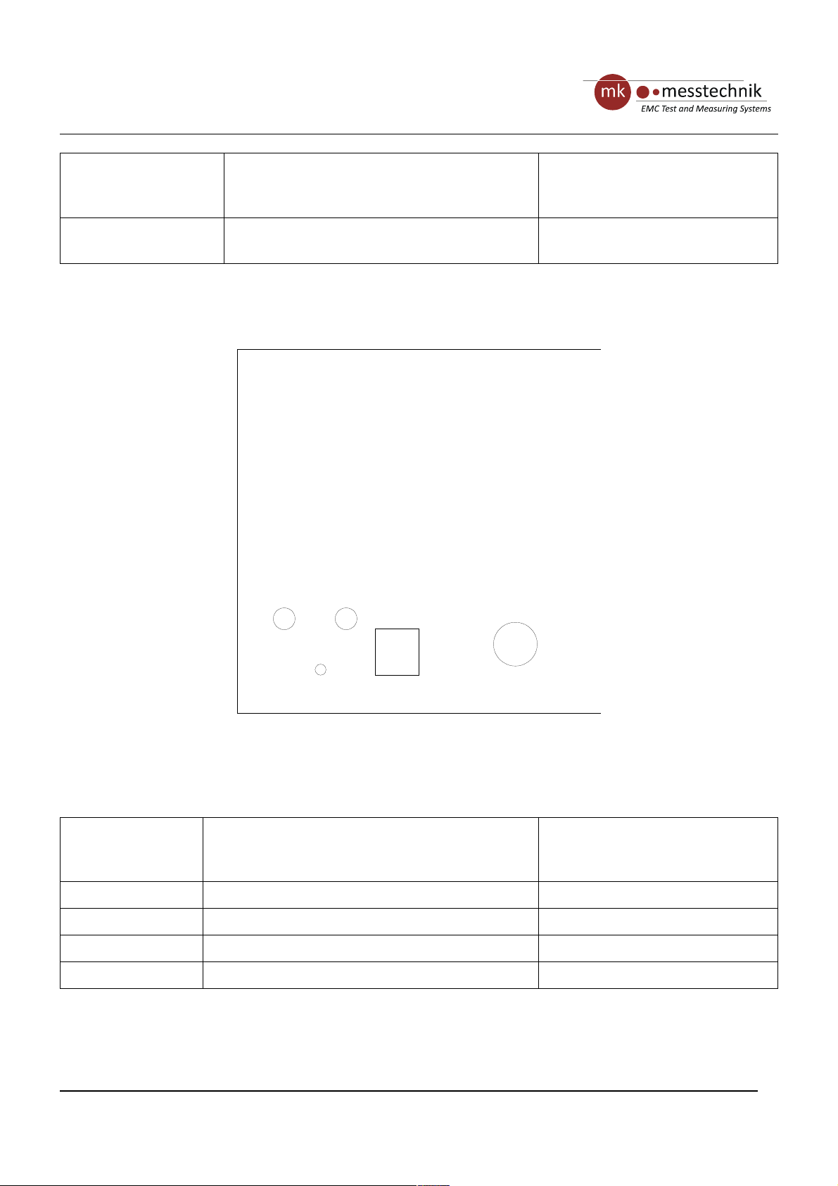
7.5 Back Side of the Mobile Device
Charge
DC-In
Optical
In
Sig Detect
Optical
Out
PC
Sig Detect Permanently on when light is received via the
optical link, permanently off when no light is
received via the optical link
Green Signal Detect LED
Optical In Connection of fiber optic cable (input) Socket FSMA
Optical Out Connection of fiber optic cable (output) Socket FSMA
PC Connection of host PC Socket USB-B
Charge DC-In Connection of charger 5-pole-socket screw connector
Page 9 / 23
Figure 7-1: back side of mobile device
Distributed by: Reliant EMC LLC, 3311 Lewis Ave, Signal Hill CA 90755, 4089165750, www.reliantemc.com
Page 10
revision 1.0
Intercom
Operating Instructions
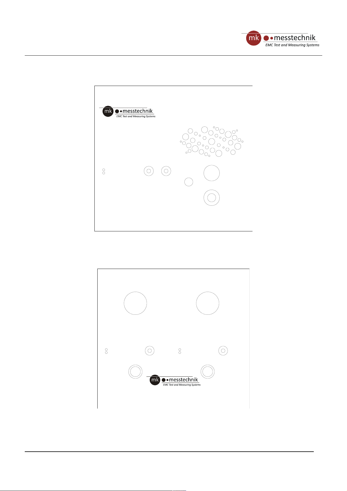
7.6 Front Side of the Console Device
dAV-TRX
Info
PTT
Power
Volume
In
Info
Power
Volume
In
PTT
Mic 1 Mic 2
Page 10 / 23
dAV-TRX
Info
Volume
Out
PTT
Power
Volume
In
Line-In
Mic
Mic
Figure 7-2: front side of console device
Figure 7-3: front side of console device with 2 channels
Distributed by: Reliant EMC LLC, 3311 Lewis Ave, Signal Hill CA 90755, 4089165750, www.reliantemc.com
Page 11
revision 1.0
Intercom
Operating Instructions
Power Permanently on when device is powered up,
permanently off when device is switched off,
blinking when talking is possible
Red LED
Info Permanently off when connection to other station
is ok, blinking when there is no optical connection
to other station, blinking once when resetting to
default
Yellow LED
Mic Capture audio signals 3-pole-socket XLR connector
PTT (Push to talk) Push and release (< 250ms) to activate/deactivate
permanent talking, push and hold (> 250ms) to talk
temporary, release to stop talking temporary
Push button
Line In /Mic
(optional)
Switch to “Line In” to activate transmission of line
in signal, switch to “Mic” to activate transmission
of mic signal
Switch button
Volume In Turn right to increase microphone gain, turn to left
to decrease microphone gain, push and hold (> 2s)
to reset settings to default
Turning knob/ Push button
(Software control)
Volume Out Turn to right to increase speaker volume, turn to
left to decrease speaker volume
Turning knob
(Hardware control)
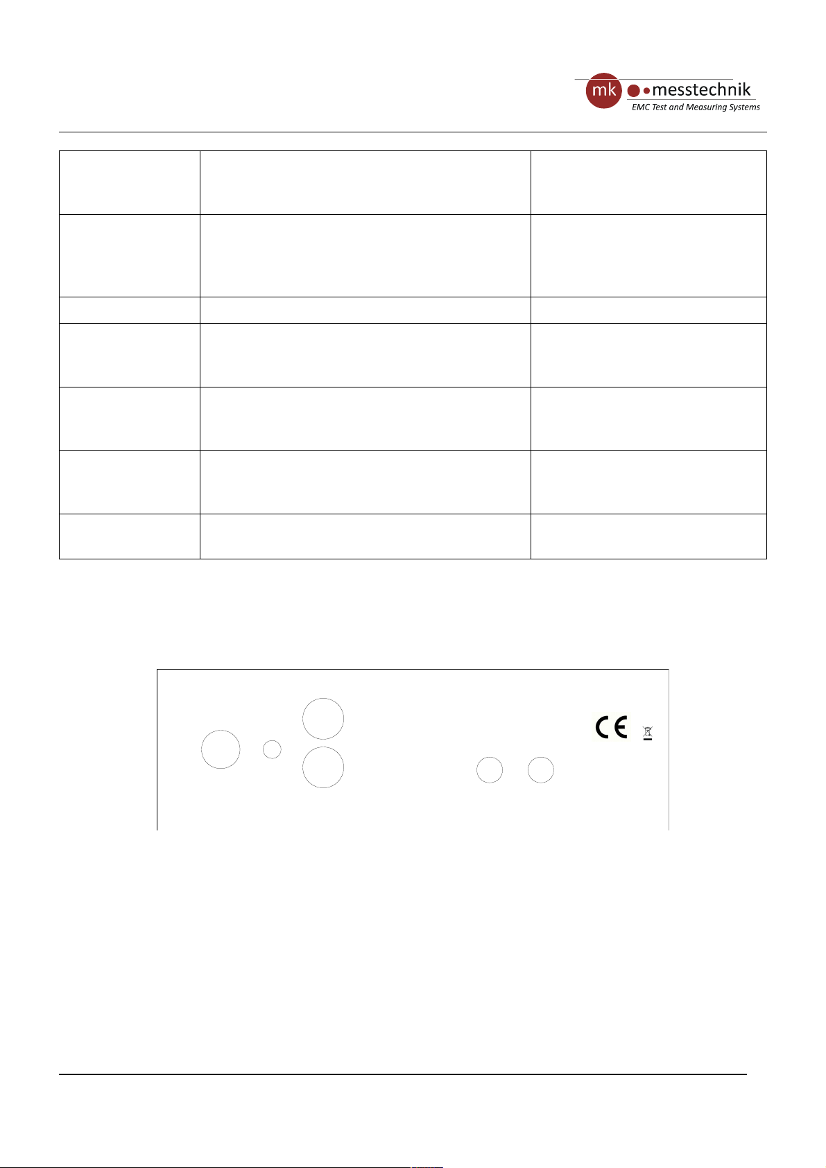
7.7 Back Side of the Console Device
Page 11 / 23
DC-In
6..12V
0,5A
dAV-TRX
Ch 1 Optical
In Out
On
Off
Line-Out
Line-In
Figure 7-4: back side of console device with line in/out
Page 12
revision 1.0
Intercom
Operating Instructions
DC-In
6..12V
0,5A
dAV-TRX
Ch 1 Optical
In Out
On
Off
Mic 2
DC-In
6..12V
1A
dAV-TRX
Ch 1 Optical
In Out
On Off
Ch 2 Optical
In Out
Audio-out
DC-In Input for power supply Plug power supply
On/Off Turn device on and off Switch button
Line-Out (optional) Output for line signal received via optical link Socket Cinch
Line-In (optional) Input for line signal transmitted via optical link Socket Cinch
Audio-Out (optional) Output for line signal received via optical link Phone jack stereo
Mic 2 (optional) Connection of secondary mic Socket SUB-D
In Connection of fiber optic cable (input) Socket FSMA
Out Connection of fiber optic cable (output) Socket FSMA
7.8 Front Side of the Secondary Mic
Page 12 / 23
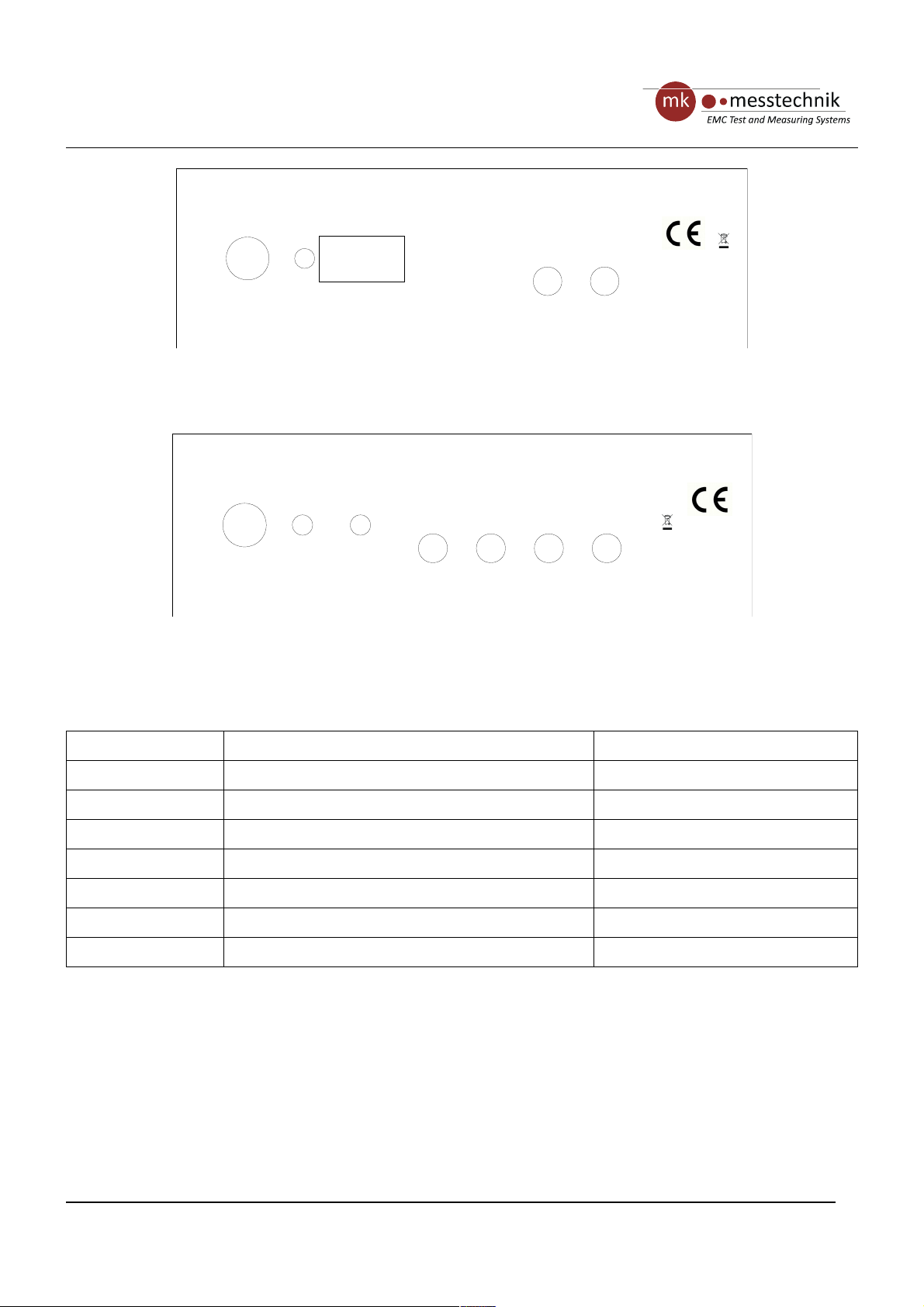
Figure 7-5: back side of console device with secondary mic
Figure 7-6: back side of console device with 2 channels
Distributed by: Reliant EMC LLC, 3311 Lewis Ave, Signal Hill CA 90755, 4089165750, www.reliantemc.com
Page 13
revision 1.0
Intercom
Operating Instructions
dAV-Mic
PTT
Power Permanently on when device is powered up,
permanently off when device is switched off,
blinking when talking is possible
Red LED
Mic Capture audio signals 3-pole-socket XLR connector
PTT (Push to talk) Push and release (< 250ms) to activate/deactivate
permanent talking, push and hold (> 250ms) to talk
temporary, release to stop talking temporary
Push button with integrated LED
7.9 Back Side of the Secondary Mic
dAV-Mic
Signal I/O
Page 13 / 23
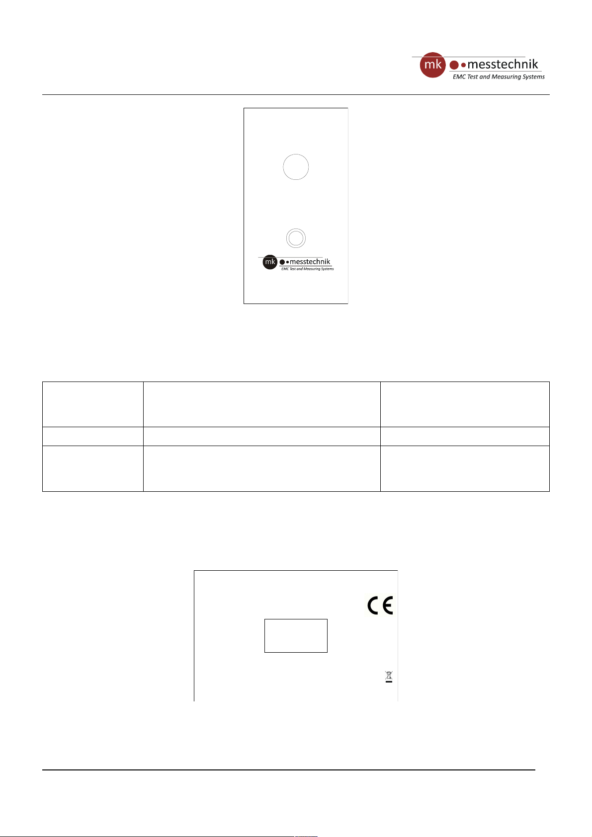
Figure 7-7: front side of
secondary mic
Figure 7-8: back side of secondary mic
Distributed by: Reliant EMC LLC, 3311 Lewis Ave, Signal Hill CA 90755, 4089165750, www.reliantemc.com
Page 14

revision 1.0
Intercom
Operating Instructions
Signal I/O Connection of console device Socket SUB-D
7.10 Initial Operation
• Turn the “Volume out” knob on both devices completely to the left
• Switch on both devices → Info LED stops blinking when an optical connections is established
• Press and hold “Volume In” knob (> 2s) on both devices to reset settings to default → Info LED blinks once
• Push and release the PTT button (< 250ms) on console device to start talking → Power LED blinks
• Turn the “Volume Out” knob on mobile device to adjust the speaker volume
• If necessary, turn the “Volume In” knob on console device to adjust the mic gain
• Switch the “Mic” button to “On” on mobile device to start talking → Power LED blinks
• Turn the “Volume Out” knob on console device to adjust the speaker volume
• If necessary, turn the “Volume In” knob on mobile device to adjust the mic gain
• Wait at least 20s until mic gain is stored in the devices
§
Speaker Damage when volume is too high
A too high speaker volume can lead to extreme loudness or an overload of the speaker. When
taking the devices into operation, turn off the speaker volume in order to avoid any damages.
Page 14 / 23
Distributed by: Reliant EMC LLC, 3311 Lewis Ave, Signal Hill CA 90755, 4089165750, www.reliantemc.com
Page 15

revision 1.0
Intercom
Operating Instructions
8 Operation
8.1 Start/Stop talking
The console device has a “PTT” (push to talk) button. Push this button to talk to the other station. You can either
talk permanently or temporarily. Push the button briefly and release it (< 250 ms) to activate the permanent
mode. You do not need to hold or operate any controls while talking in this mode. Push briefly (< 250 ms) to
deactivate the mode again. If you push and hold the button (> 250 ms), you activate the temporary mode. In this
mode, you can talk as long as you hold down the button. Releasing it deactivates the temporary mode instantly.
The mobile device has a “Mic” switch button. Switch or push this button to talk to the other station. You can either
talk permanently or temporarily. Switch the button to "On" to talk permanently. The button stays in this position
and allows you to talk to the other station until you switch the button back to "Off“. Push the button to "(On)" to
talk temporarily. You can talk as long as you hold the button in this position. The button switches automatically
back to "Off” when you release it.
Only one station can talk at a time. A blinking power LED indicates that talking is active.
Example:
The “Mic” button of the mobile device is set to permanently on. If the console “PTT” button is pushed, the mobile
device is not allowed to talk anymore, until either the console deactivates talking or the mobile device switches
the “Mic” button “Off” and “On” again.
8.2 Volume Control
The mic/line in input gains are controlled by software and can be adjusted by turning the “Volume In” knob. After
20s of inactivity, the values are permanently stored. By pushing and holding (> 2s) the “Volume In” button, the
gains can be reset to default which is indicated by a one time blinking of the “Info” LED.
The speaker output volume is controlled by hardware and can be adjusted by turning the “Volume Out” knob.
§
Speaker Damage when volume is too high
A too high speaker volume can lead to extreme loudness or an overload of the speaker. When
taking the devices into operation, turn off the speaker volume in order to avoid any damages.
Page 15 / 23
Distributed by: Reliant EMC LLC, 3311 Lewis Ave, Signal Hill CA 90755, 4089165750, www.reliantemc.com
Page 16

revision 1.0
Intercom
Operating Instructions
8.3 Line In (optional)
The devices can optionally be equipped with a “Line In/Mic” switch button and a “Line In” connector. The switch is
used to select the audio input source which can either be the mic or a line in signal. The line in signal can be
connected via the “Line In” connector. The input gains for the mic and line in signal can be adjusted
independently.
8.4 Line Out (optional)
An optional “Line Out” or “Audio-Out” connector allows routing of the audio signal received via optical link to
other devices. This is especially used in 2 channel console devices which don’t have integrated speakers.
8.5 Secondary Mic (optional)
An additional option for the console device is a connector for a secondary microphone unit. This unit consists of a
microphone and a PTT button with integrated LED. Either the secondary mic or the console device can talk with
the mobile device at a time. A blinking power/PTT LED indicates that talking is active.
Example:
The console device is set to permanent talking. If the PTT button of the secondary mic is pushed, the mic of the
console device is deactivated and the secondary mic is activated. When talking is deactivated at the secondary
mic, the mic of the console device is NOT activated again. In order to talk again, the PTT of either the secondary
mic or the console device must be pushed.
8.6 Headset Connection (optional)
If the device has installed the headset option, an external headset can be connected to the device. The headset
can be activated/deactivated via the “Headset On/Off” switch button. When the headset is activated, the speaker
is deactivated and full duplex operation is possible without acoustic feedback. E. g. both devices can talk
simultaneously. When headset is deactivated, the integrated speaker is activated and only half duplex operation is
possible. In this mode only one device can talk at a time.
Page 16 / 23
Distributed by: Reliant EMC LLC, 3311 Lewis Ave, Signal Hill CA 90755, 4089165750, www.reliantemc.com
Page 17

revision 1.0
Intercom
Operating Instructions
9 Battery and Charger
9.1 Properties
Batteries are either integrated into the devices from mk messtechnik GmbH or delivered separately as external
battery packs.
The number of cells varies and depends on the required voltages.
The related charger has the following properties:
• Power supply with power plug (Standard EU (type C or F) unless ordered otherwise, optional US (type A), UK
(type G), AU (type I))
• Integrated LEDs to display the charging level of the connected devices respectively the connected battery
packs.
• Short-circuit-proof, reverse polarity protected
• Suitable for batteries with 4 … 10 cells and a capacity of 1,0 … 10,0 Ah
• Charging process IUoU
Chargers with the charging process IUoU work basically identical to those using the IU (CCCV) charging process.
After reaching the end of charging voltage however, the device switches to trickle charging. This way a selfdischarge is avoided.
9.2 Regulations and References
Protect the batteries from heat (e.g. long exposure to direct sunlight) and fire. Do not immerse the batteries into
fluids. Otherwise there is a risk of explosions.
§
Risk of Damage and Explosion Because of Incorrect Treatment
Unintentional or incorrect treatment can damage the batteries, which can even lead to
explosion of the batteries!
Batteries that are integrated into the devices of mk messtechnik GmbH or are delivered with them, may only be
charged with the intended chargers from mk messtechnik GmbH.
These components are compatible to each other, other chargers may damage the system or may reduce the
capacity or life span of the batteries significantly.
Respect the following references when operating the chargers:
• Use chargers only for charging devices and batteries.
• Switch devices off before connecting the charger.
• Do NOT switch on the device during the charging process.
• Maximum charging current 1.2 A.
• Disconnect charger before turning on the device.
• Prior to first use, charge the batteries completely.
Page 17 / 23
Distributed by: Reliant EMC LLC, 3311 Lewis Ave, Signal Hill CA 90755, 4089165750, www.reliantemc.com
Page 18
revision 1.0
Intercom
Operating Instructions
• Charge the batteries before use if you have not used them for a longer period (self discharge of the NiMH
batteries) and after use.
• To avoid capacity loss due to the memory effect, discharge the batteries completely every 5 charging cycles. To
do this, leave the device on, until it turns off by itself. Then start the charging process as described above.
§
Risk Through High Voltage at the Charging Device
• The charger works with mains voltage.
• Security references for work with mains voltage must be followed.
!
Warning of Reduced Capacity and Life Span of the Batteries due to Maloperation
Use only the intended chargers from mk messtechnik GmbH.
Powered devices must never be used with a connected charger, e.g. for buffering an empty
battery.
Disregard can lead to a loss of capacity and a shortened life span of the battery in a short time.
9.3 Charging the Batteries (Battery Pack or Integrated into the Device)
Start of the Charging Process
• Place the battery pack or the device to charge onto a stable and skidproof surface.
• Turn off the device (see appropriate chapter for operation and operating controls).
• Connect the charger with the battery pack or the device using the designated screw connector (see
appropriate chapter for operating elements).
• Plug the power cord of the charger into the power socket.
• Do not power on the device during charging, this can damage the device.
• Check the status of the charging LED periodically (the meaning of the states are printed onto the housing of the
charger).
End of the Charging Process, after the Charging LED Displays the Status “Full”
• Make sure that the device to charge is still turned off.
• Remove the connection between the charger and the screw connectors of the battery pack or the device to
charge.
• Remove the power plug of the charger from the socket.
• The device or battery pack is now ready for operation.
Page 18 / 23
Distributed by: Reliant EMC LLC, 3311 Lewis Ave, Signal Hill CA 90755, 4089165750, www.reliantemc.com
Page 19
revision 1.0
Intercom
Operating Instructions
10 Environmentally Friendly Disposal
10.1 Disposal of Devices
All devices must be disposed according to the environmental regulations in force.
Important Notice for Disposal of Devices
• Used equipment must be collected separately and disposed in an environmentally friendly
manner
• Electrical and electronic devices must NEVER be disposed in the household waste.
• You can return old electrical and electronic devices to mk messtechnik GmbH at no cost.
10.2 Disposal of Batteries
Due to their natural capacity loss batteries must be replaced after their lifespan.
NEVER open devices or housings by yourself. Replacement of batteries must be done by mk messtechnik GmbH.
Please contact mk messtechnik GmbH for further details.
Important Notice for the Disposal of Batteries
• Disposing of batteries in the household waste is prohibited by law!
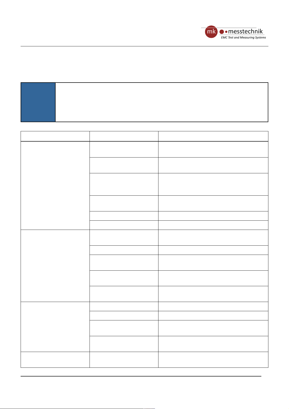
• Battery packs and devices containing batteries or environmental pollutants, are marked by
a symbol showing a crossed out garbage container (see picture on the left).
Page 19 / 23
Distributed by: Reliant EMC LLC, 3311 Lewis Ave, Signal Hill CA 90755, 4089165750, www.reliantemc.com
Page 20
revision 1.0
Intercom
Operating Instructions
11 Troubleshooting
The following list is intended to support the troubleshooting to keep downtimes as low as possible.
i
Notice!
• If problems occur that you can not solve yourself, please contact mk messtechnik GmbH for
further help.
• Please only send in devices after contacting a staff member of mk messtechnik GmbH and
receiving an RMA-number.
Error Possible Cause Solution
No or incorrect transmission
(Info LED is blinking)
Device does not receive an
optical signal
Check connectors, cables, and fibers, replace if
necessary
Fiber optic cable soiled Clean the connectors of the fiber optic cable, see
chapter 7.1
Fiber optic cable or power
cable defective or connected
incorrectly
Use the correct fiber optic cable (62.5/125µm),
check the power cable for defects and replace it
if necessary
Wrong fiber optic cable
selected
Use the correct fiber optic cable (62,5/125µm)
Batteries empty Charge batteries
Other device turned off Turn on other device
No transmission, white noise
or silence at the output
Device does not receive an
optical signal
Check fiber optic cable / light emission at the
transmitter
Batteries empty Charge batteries
Mic gain of other device too
low
Increase mic gain of other device by turning
Volume In knob
Talking in other device is
deactivated
Activate talking in other device with PTT/Mic
button
Speaker volume too low Increase speaker volume by turning Volume Out
knob
Device can not be turned on /
can not be charged
Batteries defective Send device to manufacturer
Internal fuse defect Send device to manufacturer
Charging device or charging
cable defective
Check/exchange charging device/charging cable
Batteries discharged deeply Charge battery, use different charging device if
necessary (5 cells)
General problems Defective fiber optic cable /
electrical cable or connector
Change fiber optic cable
Check connectors and cables
Page 20 / 23
Distributed by: Reliant EMC LLC, 3311 Lewis Ave, Signal Hill CA 90755, 4089165750, www.reliantemc.com
Page 21

revision 1.0
Intercom
Operating Instructions
12 Technical Data
12.1 Intercom Device
Housing Anodized aluminium housing
12.1.1 Optical Transceiver
Optical transmission Signal transmission by multimode FSMA, (62.5/125 μm)
12.1.1.1 Mobile Device
Power supply Internal battery packs (see chapter 12.3) or shielded power supply
(110 V to 230 V) for fixed installation
Dimensions (W x H x D) Approx. 100 mm x 100 mm x 150 mm
Weight Approx. 0,8 kg
Mount 1/4“- tripod thread at bottom, others upon request
Mounting plate with 1/4“-thread (W x H x D)Approx. 35 mm x 5 mm x 37 mm
Microphone Internal, mono, single ended
12.1.1.2 Console Device
Power supply Shielded power supply (110 V to 230 V) for fixed installation
Dimensions without mic (W x H x D) Approx. 246 mm x 74 mm x 186 mm
Mic length Approx. 460 mm
Weight Approx. 1.3 kg (1 channel), 1.44 kg (2 channel)
Microphone External, mono, differential
12.1.2 Secondary Mic
Power supply Passive, not needed
Dimensions without mic (W x H x D) Approx. 144 mm x 74 mm x 186 mm
Mic length Approx. 460 mm
Weight Approx. 0.7kg
Page 21 / 23
Distributed by: Reliant EMC LLC, 3311 Lewis Ave, Signal Hill CA 90755, 4089165750, www.reliantemc.com
Page 22

revision 1.0
Intercom
Operating Instructions
Microphone External, mono, differential
12.2 Charger
Input voltage AC 100 … 240 V, 50...60 Hz
Input current 0.25 … 0.3 A
Output voltage DC 4.8 … 12 V, depending on the number of detected cells
Output current, max. 0.8 A
Internal fuse T 0.8 A
Weight 0.14 kg
Type Power supply with different power plugs (Standard EU Type C, if not
stated otherwise)
Connections Cable 1.8 m with 5-pole screw connector (Binder 712 series),
suitable for systems from mk messtechnik GmbH
Temperature of operation 0 … 40°C at maximum load
Temperature of storage -40 … 70°C
Protection class IP 40
Insulation class T40/F
Relative humidity 5 % … 95 % non-condensing
Safety standard Standards IEC 60335, IEC 60601-1, IEC 61000, class II SELV
12.3 Battery Pack
Nominal voltage 6.0 V
Capacity 4 Ah
Type Nickel-metal hydride (NiMH) battery, 5 cells
Environmentally friendly disposal note See chapter 10.2
Page 22 / 23
Distributed by: Reliant EMC LLC, 3311 Lewis Ave, Signal Hill CA 90755, 4089165750, www.reliantemc.com
Page 23

revision 1.0
Intercom
Operating Instructions
13 Accessories, Spare parts
For an overview of available accessories please visit www.mk-messtechnik.com.
For spare parts, orders, and repairs please contact mk messtechnik GmbH.
Page 23 / 23
Distributed by: Reliant EMC LLC, 3311 Lewis Ave, Signal Hill CA 90755, 4089165750, www.reliantemc.com
 Loading...