

MODEL
NUMBER
MF1
OPERA
OPERA
TIONS MANUAL
TIONS MANUAL
WARNING:
IMPROPER INSTALLATION, ADJUSTMENT, ALTERATION, SERVICE OR MAINTENANCE CAN CAUSE PROPERTY
DAMAGE, INJURY OR DEATH. READ THE INSTALLATION, OPERATING AND MAINTENANCE INSTRUCTIONS
THOROUGHLY BEFORE INSTALLING OR SERVICING THIS EQUIPMENT.
PLEASE READ ALL SECTIONS OF THIS MANUAL AND RETAIN FOR FUTURE REFERENCE.
CAUTION: THIS EQUIPMENT MUST ONLY BE OPERATED WITH THE APPROPRIATE
EXHAUST ATTACHMENTS.
THIS EQUIPMENT "MUST" BE INSTALLED AND COMMISSIONED BY A PROFESSIONAL
FACTORY TRAINED TECHNICIAN
DISTRIBUTED EXCLUSIVELY TO
McDonald's
BY
GARLAND COMMERCIAL INDUSTRIES, INC.
185 EAST SOUTH STREET
FREELAND, PENNSYLVANIA 18224
TOLL FREE: (800) 446-8367
PHONE: (570) 636-1000
FAX: (570) 636-9874
Come visit us on the web at www.garland-group.com
E-mail: clamshell@garland-group.com
Rev 1 P/N MF3FT Q(092001) FAST
CAUTION MICROW
AVE EMISSIONS
DO NOT BECOME EXPOSED TO EMISSIONS FROM THE MICROWAVE GENERATOR OR
PARTS CONDUCTING MICROWAVE ENERGY
FIELD TEST
FIELD TEST
ONL
ONLYY
®

VERY IMPORTANT
PLEASE READ CAREFULLY
The QSR team is very proud to announce a new addition to our product offering. In addition to the
Clam Grill manufactured exclusively for McDonald's Corp, we bring you the "Menu-Flex Oven". The
"Menu-Flex Oven" is unique in many ways and you have been chosen to be one of a few to initially
test it!
What's so unique about it ? Well, this is a Rapid Heat, Menu Flexible Microwave Assisted
Convection Oven ! …. Yes, that's right, a Microwave Assisted Convection Oven. A Convection Oven
that will be programmed to add a sudden burst of Microwave power when needed resulting in
reduced cook times without jeopardizing the Food Quality, Taste and Safety.
The oven has a unique controller that will control menu items and categorize them! With the ovens’
flexible capabilities, you can program numerous menu items to satisfy your needs.
The enclosed information will serve as a guideline through its testing phase, as well as preliminary
service information for the local service representative. Please read all information thoroughly and
carefully. Please fill out all pertinent information as required and if there are any questions at all, feel
free to call us at 1-800-446-8367, 24 hours a day, 7 days a week... Or drop us an email at
clamshell@garland-group.com.
Thank you for working with the QSR team on this exciting
new project,
“The Menu-Flex Oven
”
brought to you exclusively by:
Garland Commercial Industries Inc.
185 East South Street
Freeland, PA 18224
Phone:(570)636-1000
Toll Free:(800)424-2411
Fax:(570)636-9874

PRECAUTIONS TO BE
OBSERVED BEFORE AND DURING
SERVICING TO AVOID POSSIBLE EXPOSURE
TO EXCESSIVE MICROWAVE ENERGY
a) Do not operate or allow the oven to be operated with the door open.
b) Make the following safety checks on all ovens to be serviced before activating the magnetron or
other microwave source , and make repairs as necessary:
1) interlock operation,
2) proper door closing
3) seal and sealing surfaces (arcing, wear, and other damage)
4) damage to or loosening of hinges and latches
5) evidence of dropping or abuse
c) Before turning on microwave power for any test or inspection within the microwave generating
compartments, check the magnetron , wave guide or transmission line, and cavity for proper alignment, integrity, and connection.
d) Any defective or misadjusted components in the interlock , monitor, door seal, and microwave
generation and transmission systems shall be repaired , replaced, or adjusted by procedures
described in this manual before the oven is released to the owner.
e) A microwave leakage check to verify compliance with the Federal Performance Standard should
be performed on each oven prior to release to the owner.

4
SAFETY
Please remember that it is wiser not to attempt a service task if you are unsure of being able to complete it competently,
quickly, and above all safely.
To avoid injury to you, and to protect the appliance from possible damage, please follow this Safety Code when servicing
these ovens.
Before attempting to repair the oven, check it for microwave leakage.
Check that the oven is not emitting microwaves, even when supposedly not in operation.
Check that the oven is not operating continuously, whether the display indicates cooking or not.
Always discharge the HT capacitors before working on the oven using a suitably insulated 10 M ohm
Resistor.
Before removing any covers from the oven, do all of the following.
•
Switch off the mains supply and remove the plug from the wall socket.
or
•
If the oven is hard wired, ensure that the power is turned off at the isolator switch.
Note:
The On/Off switch on the oven is not adequate protection against electric shock, as it does not
isolate all of the internal wiring from the mains.
Upon completion of a service on a Mealstream oven, or before reconnecting the appliance to the electrical supply for
testing, check all of the following points:
•
All internal electrical connections are correct (see wiring diagram Pages xxxxxx).
•
All wiring insulation is correct and is not touching a sharp edge.
•
All Earth connections are electrically and mechanically secure.
•
All door safety interlocks are secure and mechanically sound.
•
The door operation is smooth, and the arms run freely in the slots.
•
The door activates all three of the door interlock switches in the correct order (see pages xxxx).
•
The temperature sensor is correctly connected to the Power PCB.
•
All of the electronics are functioning correctly, and all of the touch pads are working.
•
The power output of the oven is correct.
•
Microwave emission is below permissible limit - 4 mW/cm².
•
Oven has correct 2 inch ( 50mm ) air gap all round and 2 inch ( 50mm ) above.
Airflow should not be restricted.

5
TABLE OF CONTENTS
SAFETY............................................................................................................................................4
INSTALLATION INSTRUCTIONS ....................................................................................................6
Grounding Requirement ...............................................................................................................6
Positioning the Oven.....................................................................................................................6
SPECIFICATIONS ............................................................................................................................7
DESCRIPTION OF OVEN CONTROLS...........................................................................................9
NORMAL OPERATION ..................................................................................................................10
Power Up ......................................................................................................................................10
“OFF” Mode..................................................................................................................................
10
IDLE Mode ....................................................................................................................................
10
Checking Temperatures
..............................................................................................................10
Starting a cook cycle
...................................................................................................................10
Cook Mode ...................................................................................................................................
10
Audible Alarm
...............................................................................................................................10
Cancelling a Cook Cycle .............................................................................................................11
How to - Normal Operating Modes.............................................................................................11
Product Cooking ..........................................................................................................................11
PROGRAM LOGIC CHART ...........................................................................................................12
PROGRAMMING MODES..............................................................................................................13
To Change the Remove Time .....................................................................................................13
To Change the Cook Temperature .............................................................................................13
To Change the Microwave Power...............................................................................................14
To Change the Microwave Delay Time ......................................................................................14
To Change the Microwave Cook Time.......................................................................................15
To Change the Soak Time...........................................................................................................15
To Change the Lower Heater Duty Cycle ..................................................................................16
T
o Change the Upper Heater Duty Cycle ..................................................................................16
T
o Change the STAGED HEAT Status .......................................................................................17
T
o Change the FAN CYCLE Status ............................................................................................17
TEMPERATURE CONVERSION....................................................................................................18
TEMPERATURE CONVERSION....................................................................................................19
6
This appliance must be connected to a
grounded, metallic, permanent wiring system,
or an equipment grounding conductor should
be run with the circuit conductors and connected to the equipment grounding terminal or
lead on the appliance.
2 inches
2 inches
2 inches
2 inches
32 1/2 inches
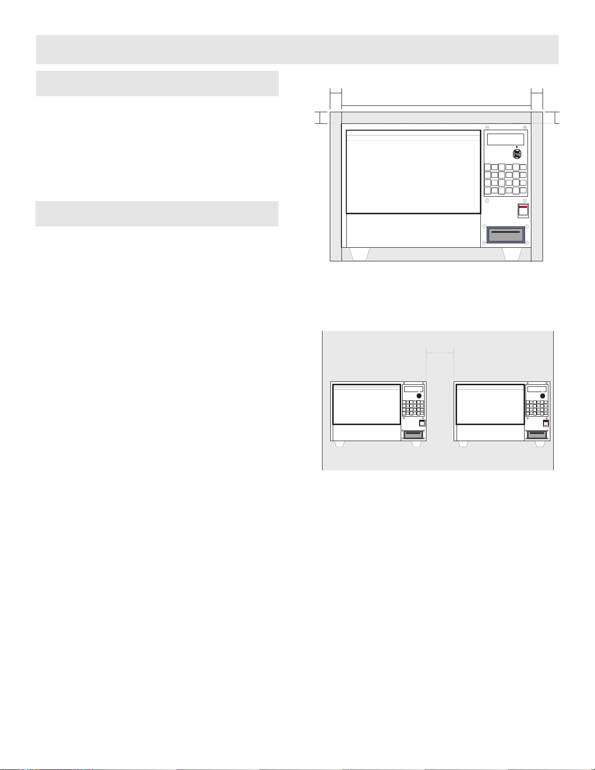
In order to maintain adequate ventilation for air
intake and exhaust, and to allow access for
cleaning filters, you must allow a minimum of 2
inches ( 50 mm ) clearance at the sides and
rear of the oven, and at least 2 inches ( 50 mm
) above (Figure 3-1).
Air intake temperature should not exceed 60°F
excessive temperature will lead to reduced
operating duty cycle or premature ageing of
internal components.
Failure to comply with these conditions will
invalidate the warranty.
NEVER Install an oven above fryers,
grills, griddles or any other major heat source.
ALWAYS Place containers in the cavity
carefully - impact damage may chip the vitreous enamel coating on the runners and baffle
plate.
Figure 3-1 - Manufactures Recommended
Clearances
Figure 3-2 -Center Clearance Between Ovens
Positioning the Oven
Grounding Requirement
INSTALLATION INSTRUCTIONS
4.00"

SPECIFICATIONS
60 HZ 50 HZ
XYZ XY Z NL2L3
3.00 6.6 0.0 12.4 27.5 15.0 208
3.00 6.6 0.0 27.5 10.8 23.8 13.0 15.0 12.5 240
3.00 6.6 0.0 30.0 11.8 26.0 14.2 16.4 13.6 220
15.6 13.0 230
*
VOLTS
NOMINAL AMPS PER LINE
60 HZ
KW PER PHASE
6.60
50 HZ
TOTA L K W
SINGLE PHASE
THREE PHASE
7
19 7/8
4
32 1/2
FRONT VIEW
(DOOR CLOSED)
12 13/16
26 11/16
SIDE VIEW
(DOOR OPEN)

SPECIFICATIONS
8
Microwave 100%
1425W
Convection
3000W
Power Output
Combination
1425W + 3000W
Height
23.5 inches ( 597mm )
Width
32.5 inches ( 826mm )
External
Dimensions
Depth
28.3 inches ( 719 mm )
Height
32 inches ( 815 mm )
Width
31.5 inches ( 795 mm )
Manufacturers
Recommended
clearances
Depth
25 inches ( 635 mm)
Height
10.2 inches ( 260mm )
Width
19.3 inches ( 490mm )
Depth
14.2 inches ( 360mm )
Internal
Dimensions
Capacity
1.73 ft³ ( 48.99 litres )
Nett
198 lb.s ( 90 kg )
Weight
Gross packed
233 lbs ( 106 kg )
Construction
Cavity
Casework
304 Stainless Steel
Settings
Microwave
Temperature
Timer

9
DESCRIPTION OF OVEN CONTROLS
A
E
D
C
B
Letter Description Function
A Oven Dis play Displays Current Menu Item Selec ted, and current s tatus of Oven
B Oven Controller Controls all menu items, times, temperatures, & microwave power.
C Start / Stop Button Starts / Stops Cook Cycles.
D Main Power Swit ch Turns Oven Power On or Off.
E Card Reader (Inac tive) For Future Use
F "Heat On" Light Indicates that Convection oven heat is ON
G "Micro On" LED Indicates that Microwave Oven power is ON
H CANCEL Pushbut ton
I CLEAN Pushbutton
J MICRO TEST Pushbtton
Indicates that
Convection heat is
on
Indicates that
Microwave heat is
on
Starts / Stops a
Cook Cycle
Cancel’s a Cook
Cycle, Step up 1 Level
in the Programming
tier.
Maintain’s or
brings oven to
optimum cleaning
temperature
Starts Microwave
test procedure.
Heat On
Micro On
Start
Stop
Biscuits
123
FULL
BAGELS
456
789
Pies
6
Micro
test
0
Biscuits
Half
Pies
12
COOKIES
CLEAN
Cancel
Biscuits
Qtr
Pies
8
Option
CANCEL

Upon power up of the Garland Menu-Flex
oven controller will display “OFF”, and will be
in the “OFF” mode.
You may start a cook cycle as long as the
display doesn’t flash “TOO COOL” or “TOO
HOT”. - Load product and PRESS START /
STOP BUTTON.
10
There are various options in the “OFF” mode.
1. Pressing the TEMP button – Checks the
actual temperature of the oven.
2. Pressing and Holding the PROG button
for 3 seconds – Enters the program mode.
3. Pressing any numbered button – Selects
a menu item.
The IDLE mode is when the oven is up to set
temperature and stabilized within +/- 20
Degrees Fahrenheit of the selected menu
items set point.
20 Degrees Above Set Temperature “TOO HOT”
20 Degrees Below Set Temperature “TOO COOL”
The controller will alternately display one of
the above Messages and the selected menu
item if the temperature sensed is +/- 20
Degrees Fahrenheit of the selected menu
items set point.
If ANY of the above-mentioned “TOO HOT”
or “TOO COOL” scenarios exist, initiating a
cook cycle will be PROHIBITED until proper
operating temperature is reached.
You may check the actual oven temperature
by pressing the TEMP button.
You may also check the actual oven
temperature and the set point for a specific
menu item by pressing the number of that
menu item and pressing TEMP within 3
seconds.
The controller will return to its previous menu
setting after 3 seconds.
When the operator presses the
START/STOP button to initiate a cook cycle,
the START/STOP LED turns on and the first
line of the display will show that menu item
that is being cooked. The second line will
show the time remaining in the cook cycle.
Ex:
Upon completion of the cook cycle, the
display will show “REMOVE” in the second
line of the display window, and an audible
alarm will sound.
Ex:
BISCIUTS
REMAINING 01:30
BISCIUTS
REMOVE
The audible alarm can be programmed in the
controller for either “MANUAL” or “AUTO”.
•
Under the MANUAL mode, the audible
alarm will sound at the end of the cook
cycle, and will continue to sound until the
operator presses the START/STOP
button.
•
Under the AUTO mode, the audible alarm
will sound at the end of the cook cycle,
and sound for ONLY 5 seconds.
Audible Alarm
Cook Mode
Starting a cook cycle
Checking Temperatures
IDLE Mode
“OFF” Mode
Power Up
NORMAL OPERATION

The operator can cancel a cook cycle at any
time by pressing and holding the
START/STOP button for 3 seconds. The
audible will sound for 1 second, and the
controller will return to the IDLE mode.
There are four (4) recipes programmed in the
controller:
•
Breakfast – Breakfast items EARLY AM
•
LATE AM
•
Lunch – Lunch Menu Items
Each recipe allows for 11 different products
for each numbered button on the controller.
11
NOTE!
If the door is opened during the
cooking cycle, the cook timer will stop
and the controller will read “DOOR
OPEN” on the second line of the
display. The cooking cycle will
continue when the door is shut.
During the cooking cycle the PROG
button is disabled and the operator will
NOT be permitted to enter the
programming mode.
1. Cook Temperature
2. Cook Time
3. Microwave Delay
4. Microwave Power Level
5. Microwave Time
6. Soak Time
7. Staged Heat
8. Fan Cycle
9. Upper Heater Duty Cycle
10. Lower Heater Duty Cycle
When a cook cycle is started:
1. The selected menu items’ programmed cook timer is initiated and begins to time down.
2. The selected menu items’ set point temperature is monitored and maintained.
3. The HEAT ON LED light is on when the convection oven heaters are heating.
4. The MICRO ON LED light is on when the microwave assist is called for.
5. Microwave Delay - The time in which the controller waits during the cook cycle before the
microwave assist turns on.
6. Microwave Power Level – The Power Level of the Microwave assist.
7. Microwave Time – The time in which the Microwave assist is active inside of the oven.
8. Soak Time – Soak Time is an idle period for the oven helping to equilibrate temperature of
product.
DURING THE SOAK TIME, THE UPPER ELEMENT, THE LOWER ELEMENT, AND THE FAN
MOTOR ARE TURNED OFF
TO DISABLE THE SOAK TIME, SET THE SOAK TO “0”
Product Cooking
How to - Normal Operating Modes
Cancelling a Cook Cycle

PROGRAM LOGIC CHART
12
PROG
Press and Hold for 3 seconds
Main Menu
2 8
2
Main Menu
Edit Menu Item
Main Menu
Time Of Day
8
PROG
Select Product
XXXXXXXX
2
Main Menu
System Info
8
PROG
Model Number
Software Number
Download Number
1 2 3
2
Main Menu
Service Menu
8
PROG
Temp Display
Cal Offset
Heaters OFF Time
Heaters ON Time
4 5 6
7 8
PROG
Cancel
Cook Temp
Cook Time
Micro Delay
Micro Power
Micro Time
Soak Time
Staged Heat
Fan Cycle
Upper Heater Duty Cycle
Lower Heater Duty Cycle
Hold Time
Product Name
9

1. PRESS and HOLD the PROG button for
3 seconds. Controller will display:
MAIN MENU
EDIT MENU ITEM
2. PRESS the PROG button 1X. Controller
will display “.SELECT PRODUCT"
3. SELECT the desired menu item button
with a number on the controller.
4. Controller will display the menu item.
5. PRESS the PROG button 3X until
“COOK TIME XX:XX” appears in the
display.
6. ENTER the desired cook time with the
corresponding numbered buttons.
Ex. Entering 4 minutes for menu item
that is set for 3:45 will follow like:
Enter 0-4-0-0 for 4 Minutes
7. Controller will display " Remove Time
XX:XX "
8. PRESS the START/STOP button to exit
the programming mode and return to the
menu item previously selected.
1. PRESS and HOLD the PROG button for
3 seconds. Controller will display:
MAIN MENU
EDIT MENU ITEM
2. PRESS the PROG button 1X. Controller
will display “.SELECT PRODUCT"
3. SELECT the desired menu item button
with a number on the controller.
4. Controller will display the menu item.
5. PRESS the PROG button 2X until
“COOK TEMP XXXF” appears in the
display.
6. ENTER the desired cook temperature
with the corresponding numbered
buttons.
Ex. Entering 345º F for menu item that
is set for 400º F will follow like:
Enter 3-4-5 for 345 degrees
7. Controller will display " REMOVE TIME
XXX ".
8. PRESS the START/STOP button to exit
the programming mode and return to the
menu item previously selected.
13
TO ENTER THE PROGRAMMING MODE, THE UNIT MUST BE IN THE “OFF” OR “IDLE” MODE.
All Timers programmed in the MenuFlex are
timers programmed in “MM-SS” format:
MM-SS
Minutes Seconds
To Change the Cook Temperature
To Change the Remove Time
PROGRAMMING MODES

PROGRAMMING MODES
1. PRESS and HOLD the PROG button for
3 seconds. Controller will display:
MAIN MENU
EDIT MENU ITEM
2. PRESS the PROG button 1X. Controller
will display “.SELECT PRODUCT"
3. SELECT the desired menu item button
with a number on the controller.
4. Controller will display the menu item.
5. PRESS the PROG button 4X until
“MICRO DELAY XX: XX” appears in the
display.
6. ENTER the desired Microwave Delay
time with the corresponding numbered
buttons.
7. Ex. Entering 4 minutes for menu item
that is set for 3:45 will follow like:
Enter 0-4-0-0 for 4 Minutes
8. Controller will display " MICRO DELAY
XX: XX "
9. PRESS the START/STOP button to exit
the programming mode and return to the
menu item previously selected.
1. PRESS and HOLD the PROG button for
3 seconds. Controller will display:
MAIN MENU
EDIT MENU ITEM
2. PRESS the PROG button 1X. Controller
will display “.SELECT PRODUCT"
3. SELECT the desired menu item button
with a number on the controller.
4. Controller will display the menu item.
5. PRESS the PROG button 5X until
“MICRO PWR XXX%” appears in the
display.
6. ENTER the desired Microwave Power
with the corresponding numbered
buttons.
Button 2 - Increases Microwave Power in
increments of 5%.
Button 8 - Decreases Microwave Power in
increments of 5%.
7. Controller will display " MICRO POWER
XX% "
8. PRESS the START/STOP button to exit
the programming mode and return to the
menu item previously selected.
To Change the Microwave Delay Time
To Change the Microwave Power
14
The Microwave Delay Time is the time in which during
the cook cycle, the controller will be delayed before the
Microwave Time starts.
For more information see page xx.
The Microwave Power is the percentage of power that
the magnetron puts out during the Microwave Time.
For more information see page xx.
IMPORTANT NOTE: All Timers programmed
in the MenuFlex are timers programmed in
“MM-SS” format:
MM-SS
Minutes Seconds

PROGRAMMING MODES
1. PRESS and HOLD the PROG button for
3 seconds. Controller will display:
MAIN MENU
EDIT MENU ITEM
2. PRESS the PROG button 1X. Controller
will display “SELECT PRODUCT"
3. SELECT the desired menu item button
with a number on the controller.
4. Controller will display the menu item.
5. PRESS the PROG button 6X until
“MICRO TIME XX:XX” appears in the
display.
6. ENTER the desired Microwave Time with
the corresponding numbered buttons.
Ex. Entering 4:00 for menu item that is
set for 3:45 will follow like:
Enter 0-4-0-0 for 4 Minutes
7. Controller will display " MICRO TIME XX:
XX ".
8. PRESS the START/STOP button to exit
the programming mode and return to the
menu item previously selected.
1. PRESS and HOLD the PROG button for
3 seconds. Controller will display:
MAIN MENU
EDIT MENU ITEM
2. PRESS the PROG button 1X. Controller
will display “.SELECT PRODUCT"
3. SELECT the desired menu item button
with a number on the controller.
4. Controller will display the menu item.
5. PRESS the PROG button 7X until “SOAK
TIME XX:XX” appears in the display.
6. ENTER the desired Soak Time with the
corresponding numbered buttons.
Ex. Entering 4 Minutes for menu item
that is set for 3:35 will follow like:
Enter 0-4-0-0 for 4 Minutes
7. Controller will display " SOAK TIME XX:
XX ".
8. PRESS the START/STOP button to exit
the programming mode and return to the
menu item previously selected.
15
The Microwave Cook Time is the Time DURING THE
COOK TIME that the Microwave power is ON.
For more information see page xx.
The Soak Time is the time the microwaves, and convection heat can penetrate the product inside the oven.
For more information see page xx.
IMPORTANT NOTE: All Timers programmed
in the MenuFlex are timers programmed in
“MM-SS” format:
MM-SS
Minutes Seconds
IMPORTANT NOTE: All Timers programmed
in the MenuFlex are timers programmed in
“MM-SS” format:
MM-SS
Minutes Seconds
To Change the Soak Time
To Change the Microwave Cook Time

PROGRAMMING MODES
1. PRESS and HOLD the PROG button for
3 seconds. Controller will display:
MAIN MENU
EDIT MENU ITEM
2. PRESS the PROG button 1X. Controller
will display “SELECT PRODUCT"
3. SELECT the desired menu item button
with a number on the controller.
4. Controller will display the menu item.
5. PRESS the PROG button 10X until
“UPPER HEATER XXX%” appears in the
display.
6. ENTER the desired Upper Heater Duty
Cycle Power with the corresponding
numbered buttons.
Button 2 - Increases Upper Heater Duty
Cycle by increments of 5%.
Button 8 - Decreases Upper Heater Duty
Cycle by increments of 5%.
7. Controller will display " UPPER HEATER
XXX% "
8. PRESS the START/STOP button to exit
the programming mode and return to the
menu item previously selected.
1. PRESS and HOLD the PROG button for
3 seconds. Controller will display:
MAIN MENU
EDIT MENU ITEM
2. PRESS the PROG button 1X. Controller
will display “SELECT PRODUCT"
3. SELECT the desired menu item button
with a number on the controller.
4. Controller will display the menu item.
5. PRESS the PROG button 11X until
“LOWER HEATER XXX%” appears in
the display.
6. ENTER the desired Lower Heater Duty
Cycle Power with the corresponding
numbered buttons.
Button 2 - Increases Lower Heater Duty
Cycle by increments of 5%.
Button 8 - Decreases Lower Heater Duty
Cycle by increments of 5%.
7. Controller will display " LOWER HEATER
XXX% "
8. PRESS the START/STOP button to exit
the programming mode and return to the
menu item previously selected.
16
To Change the Upper Heater Duty Cycle
The Upper Duty Cycle is the percentage of time that
the upper heating elements are on during the Cook
Time.
For more information see page xx.
The Lower Duty Cycle is the percentage of time that
the lower heating elements are on during the Cook
Time.
For more information see page xx.
To Change the Lower Heater Duty Cycle

PROGRAMMING MODES
1. PRESS and HOLD the PROG button for
3 seconds. Controller will display:
MAIN MENU
EDIT MENU ITEM
2. PRESS the PROG button 1X. Controller
will display “SELECT PRODUCT"
3. SELECT the desired menu item button
with a number on the controller.
4. Controller will display the menu item.
5. PRESS the PROG button 8X until
“STAGED HEAT (YES/NO)” appears in
the display.
6. To select the desired STAGED HEAT
status, PRESS BUTTON 2 to scroll
between YES or NO.
7. Controller will display " STAGED HEAT
(YES / NO) "
8. PRESS the START/STOP button to exit
the programming mode and return to the
menu item previously selected.
1. PRESS and HOLD the PROG button for
3 seconds. Controller will display:
MAIN MENU
EDIT MENU ITEM
2. PRESS the PROG button 1X. Controller
will display “SELECT PRODUCT"
3. SELECT the desired menu item button
with a number on the controller.
4. Controller will display the menu item.
5. PRESS the PROG button 9X until “FAN
CYCLE (YES/NO)” appears in the
display.
6. To select the desired FAN CYCLE
status, PRESS BUTTON 2 to scroll
between YES or NO.
7. Controller will display " FAN CYCLE
(YES / NO) "
8. PRESS the START/STOP button to exit
the programming mode and return to the
menu item previously selected.
17
The Staged Heat Function is the Degree Hysteresis in
which the heating elements will cycle.
For more information see page xx.
The Fan Cycle Status is the status in which the
Convection Fan will operate in conjuction with the
Heating Elements.
For more information see page xx.
To Change the FAN CYCLE Status
To Change the STAGED HEAT Status

CFCFCFCFCF
27 80 54 128 80 176 107 224 134 272
27 81 54 129 80 177 107 225 134 273
28 82 55 130 81 178 108 226 134 274
28 83 55 131 81 179 108 227 135 275
29 84 56 132 82 180 109 228 135 276
30 85 56 133 83 181 110 229 136 277
30 86 57 134 83 182 110 230 137 278
31 87 57 135 84 183 111 231 137 279
31 88 58 136 84 184 111 232 138 280
32 89 59 137 85 185 112 233 138 281
32 90 59 138 85 186 112 234 139 282
33 91 60 139 86 187 113 235 139 283
33 92 60 140 86 188 114 236 140 284
34 93 61 141 87 189 114 237 141 285
34 94 61 142 88 190 115 238 141 286
35 95 62 143 88 191 115 239 142 287
36 96 62 144 89 192 116 240 142 288
36 97 63 145 89 193 116 241 143 289
37 98 63 146 90 194 117 242 143 290
37 99 64 147 90 195 117 243 144 291
38 100 64 148 91 196 118 244 144 292
38 101 65 149 91 197 119 245 145 293
39 102 65 150 92 198 119 246 146 294
40 103 66 151 93 199 120 247 146 295
40 104 66 152 94 200 120 248 147 296
41 105 67 153 94 201 121 249 147 297
41 106 68 154 94 202 121 250 148 298
42 107 68 155 95 203 122 251 148 299
42 108 69 156 95 204 122 252 149 300
43 109 70 157 96 205 123 253 149 301
43 110 70 158 97 206 124 254 150 302
44 111 71 159 97 207 124 255 151 303
44 112 71 160 98 208 125 256 151 304
45 113 72 161 98 209 125 257 152 305
45 114 72 162 99 210 126 258 152 306
46 115 73 163 99 211 126 259 153 307
46 116 74 164 100 212 127 260 153 308
47 117 74 165 101 213 127 261 154 309
48 118 75 166 101 214 128 262 154 310
48 119 75 167 102 215 128 263 155 311
49 120 76 168 102 216 129 264 156 312
49 121 76 169 103 217 130 265 156 313
50 122 77 170 103 218 130 266 157 314
50 123 77 171 104 219 130 267 157 315
51 124 78 172 105 220 131 268 158 316
52 125 78 173 105 221 131 269 158 317
52 126 79 174 106 222 132 270 159 318
53 127 79 175 106 223 133 271 159 319
TEMPERATURE CONVERSION

19
TEMPERATURE CONVERSION
CFCFCFCFCF
160 320 187 368 213 416 240 464 267 512
161 321 187 369 214 417 241 465 267 513
161 322 188 370 214 418 241 466 268 514
162 323 188 371 215 419 242 467 268 515
162 324 189 372 216 420 242 468 269 516
163 325 189 373 216 421 243 469 269 517
163 326 190 374 217 422 243 470 270 518
164 327 191 375 217 423 244 471 271 519
164 328 191 376 218 424 244 472 271 520
165 329 192 377 218 425 245 473 272 521
166 330 192 378 219 426 246 474 272 522
166 331 193 379 219 427 246 475 273 523
167 332 193 380 220 428 247 476 273 524
167 333 194 381 221 429 247 477 274 525
168 334 194 382 221 430 248 478 274 526
168 335 195 383 222 431 248 479 275 527
169 336 196 384 222 432 249 480 276 528
169 337 196 385 223 433 249 481 276 529
170 338 197 386 223 434 250 482 277 530
171 339 197 387 224 435 241 483 277 531
171 340 198 388 224 436 241 484 278 532
172 341 198 389 225 437 252 485 278 533
172 342 199 390 226 438 252 486 279 534
173 343 199 391 226 439 253 487 279 535
173 344 200 392 227 440 253 488 280 536
174 345 201 393 227 441 254 489 281 537
174 346 201 394 228 442 254 490 281 538
175 347 202 395 228 443 255 491 282 539
176 348 202 396 229 444 256 492 282 540
176 349 203 397 229 445 256 493 283 541
177 350 203 398 230 446 257 494 283 542
177 351 204 399 231 447 257 495 284 543
178 352 204 400 231 448 258 496 284 544
178 353 205 401 232 449 258 497 285 545
179 354 206 402 232 450 259 498 285 546
179 355 206 403 233 451 259 499 286 547
180 356 207 404 233 452 260 500 287 548
181 357 207 405 234 453 261 501 287 549
181 358 208 406 234 454 261 502 288 550
182 359 208 407 235 455 262 503 288 551
182 360 209 408 236 456 262 504 289 552
183 361 209 409 236 457 263 505 290 553
183 362 210 410 237 458 263 506 290 554
184 363 211 411 237 459 264 507 291 555
184 364 211 412 238 460 264 508 291 556
185 365 212 413 238 461 265 509 292 557
186 366 212 414 239 462 266 510 292 558
186 367 213 415 239 463 266 511 293 559

MANUFACTURED EXCLUSIVELY FOR
McDonald's
BY
Merrychef Limited.
Station Road West
Ash Vale Aldershot Hampshire GU12 5XA
United Kingdom
PHONE: +44 (0) 1252 371000
FAX: +44 (0) 1252 371007
Come visit us on the web at
http://www.merrychef.co.uk/
E-mail: marketing@merrychef.co.uk
®
 Loading...