

Page 1
USER GUIDE
Page 2

ii
Meridian 271 Digital Theatre Controller User Guide
Important safety instructions
Read the instructions.
•
Keep these instructions.
•
Follow all instructions.
•
Do not use this apparatus near water.
•
Clean only with a dry cloth.
•
Install only in accordance with the manufacturer’s instructions.
•
Refer all servicing to approved service personnel.
•
WARNING: TO REDUCE THE RISK OF FIRE OR ELECTRIC
SHOCK, DO NOT EXPOSE THIS APPARATUS TO RAIN OR
MOISTURE.
This apparatus has been designed with Class 1 construction
and must be connected to a mains socket outlet with a
protective earthing connection (the third grounding pin).
This apparatus does not include a power switch. The apparatus
may be isolated from mains power either by unplugging the
power connector from the rear of the unit, or by unplugging the
connector at the opposing end of the power cord or cable from
its supply outlet. As a result, either or both of these connectors
should remain accessible.
Safety warnings
WARNING!
Caution: to reduce the risk of electric shock, do not remove
cover. No user serviceable parts inside. Refer servicing to
qualified service personnel.
RISK OF ELECTRIC SHOCK – DO NOT OPEN
ATTENTION!
NE PAS OUVRIR – RISQUE DE DÉCHARGE ÉLECTRIQUE
The lightning flash with arrowhead symbol, within an
equilateral triangle, is intended to alert the user to the
presence of uninsulated “dangerous voltage” within the
product’s enclosure that may be of sufficient magnitude
to constitute a risk of electric shock to persons.
The exclamation point within an equilateral triangle is
intended to alert the user to the presence of important
operating and maintenance (servicing) instructions in
the literature accompanying the appliance.
Page 3

Meridian 271 Digital Theatre Controller User Guide
≤2000m
iii
Climate
The equipment has been designed for use in moderate climates
and in domestic situations.
Only use at an altitude not exceeding 2000m.
Safety warnings
Do not expose the unit to dripping or splashing.
•
Do not place any object filled with liquid, such as a vase, on
•
the unit.
Do not place naked flame sources, such as lighted candles,
•
on the unit.
To avoid overheating
Do not position the product in direct sunlight.
•
Do not position the product near heat sources, such as a
•
radiator.
Do not position the product on a soft surface such as a
•
carpet.
Leave at least 10cm around the product to ensure sufficient
•
ventilation.
To avoid interference
Do not position the unit near strong electrical or magnetic
•
radiation, such as near a power amplifier.
Radio interference
FCC Warning: This equipment generates and can radiate
radio frequency energy and if not installed and used correctly
in accordance with our instructions may cause interference to
radio communications or radio and television reception. It has
been type-tested and complies with the limits set out in Subpart
J, Part 15 of FCC rules for a Class B computing device. These
limits are intended to provide reasonable protection against such
interference in home installations.
EEC: This product has been designed and type-tested
to comply with the limits set out in EN55032:2015 and
EN55024:2010 + A1:2015.
Page 4

iv
Meridian 271 Digital Theatre Controller User Guide
Copyright and acknowledgements
Sales and service in the UK
Meridian Audio Ltd, Latham Road, Huntingdon,
Cambridgeshire, PE29 6YE, England.
Tel (01480) 445678
Fax (01480) 445686
Designed and manufactured in
Meridian Audio Ltd, Latham Road, Huntingdon,
Cambridgeshire, PE29 6YE, England.
the UK
Visit us on the Web
www.meridian-audio.com
Copyright © 2018 Meridian Audio Ltd.
Part no: P88457
MHR: this product incorporates copyright protection technology
covered by certain patent applications and intellectual property
of Meridian Audio Ltd. This technology is provided for the
express purpose of securely containing copyright audio within
the Meridian System only. Reverse engineering or circumvention
of this protection is strictly prohibited.
Boothroyd|Stuart Meridian, Meridian, and Sooloos are registered
trademarks of Meridian Audio Ltd.
This guide was produced by:
Human-Computer Interface Ltd, www.interface.co.uk
Product registration
Register your Meridian 271 Digital Theatre Controller at:
www.meridian-audio.com
Page 5

Meridian 271 Digital Theatre Controller User Guide
Contents
Introduction 1
v
Specifications
Unpacking
Applications
Configuring the 271 Digital Theatre Controller 1
Controlling the 271 Digital Theatre Controller 18
Index 2
3
4
6
0
0
Page 6

Introduction
Meridian 271 Digital Theatre Controller User Guide
1
The Meridian 271 Digital Theatre Controller allows you to
integrate Meridian DSP loudspeakers with a variety of AV
systems to create a digital or analogue theatre that takes
advantage of Meridian’s authentic, natural sound.
Designed to work with any processor on the market, the 271 is
a High Resolution interface that allows you to design and build
high performance theatre systems with 20 or more channels.
The 271 is rack-mountable and can be stacked to give 40 or
even 60 audio output channels, all with Meridian’s (MHR) High
Resolution Audio output and a simple IP control interface.
Audio inputs
The 271 supports 16 channels of analogue audio on either
single-ended or balanced input connections (RCA or 2 x 8
channel DB25 connectors).
It also provides balanced digital input options available to
support 16 channels of digital audio fed from Trinnov, Datasat
and Storm Audio processors (2 x RJ45 and 1 x DB25).
The 271 includes a SpeakerLink input for connecting a
Meridian source to the main left and right loudspeakers.
Audio outputs
The 271 provides 16 + 4 digital audio outputs on SpeakerLink
connections for use with Meridian DSP loudspeakers using high
precision 96kHz/24-bit analogue to digital conversion.
The digital outputs support Meridian High Resolution (MHR)
encoding which improves audio quality compared to a standard
digital audio stream by improving jitter characteristics within the
associated electronic circuitry.
The 271 also provides 16 + 4 analogue audio outputs on
unbalanced RCA connectors to allow the use of passive
loudspeakers.
Inputs 1 to 16 are mapped in parallel to both sets of 16
outputs, analogue and digital, providing support for mixed
systems using combinations of analogue and Meridian DSP
loudspeakers.
The two sets of four additional outputs (four digital and four
analogue) can be independently configured to duplicate any
of the 16 input channels to provide feeds for a wide range of
combinations of loudspeakers and subwoofers.
Page 7

2
Meridian 271 Digital Theatre Controller User Guide
System integration
The 271 Digital Theatre Controller is designed to be both
configured and controlled via its Ethernet socket.
The 271 can be configured simply by entering the product’s IP
address into a standard web browser; this then gives access to
the range of setup and operational options.
Trigger input and output connections allow coordinated
switching of components within systems using a mix of speaker
types, such as enabling a power amplifier.
The 271 supports Meridian Comms so it can be controlled
from a DSP loudspeaker using a MSR+ remote or a product
connected to the SpeakerLink input of the 271.
The 271 can also be controlled via Ethernet using IP Control
and third party control drivers.
Accessories
The following accessories are available for the 271:
A Meridian G12 remote eye to receive infra red signals.
•
A Meridian MSR+ or AC200 remote to control the 251 via
•
the G12.
An 8-channel balanced XLR to DB25 cable.
•
Page 8

Meridian 271 Digital Theatre Controller User Guide
Specifications
Audio outputs
20 unbalanced analogue outputs on RCA phono connectors.
•
20 SpeakerLink digital outputs.
•
Audio inputs
16 unbalanced analogue inputs on RCA phono connectors.
•
16 balanced analogue inputs on twin DB25 connectors
•
Analogue inputs are converted to digital audio at 96kHz/24bit.
One SpeakerLink input for direct, bit-perfect, pass-through of
•
two-channel digital audio.
Digital 16-channel input on DB25 connector (Trinnov pin
•
configuration).
Digital 16-channel AES input on twin RJ45 connector
•
(Datasat and Storm Audio pin configuration).
Digital inputs can accept sample rates from 44.1kHz to
192kHz, up to 24-bit precision.
Control signals
Ethernet connection for IP Control/control driver support for
•
third party control systems.
One IR input, compatible with the Meridian G12 remote IR
•
sensor.
Trigger input on 3.5mm jack to enable remote on/off
•
switching.
Trigger output on 3.5mm jack to allow use in-line between a
•
processor and power amplification in system featuring passive
speakers.
Controls and indicators
Front panel button for turning on or off.
•
Front panel indicator for standby state and analogue clipping
•
indicator.
Physical
Dimensions: 440mm x 88mm x 358mm (17.3" x 3.5" x 14.1")
•
(W x H x D without feet or connectors).
Weight: 5.5kg (12.0lb).
•
Housed in a rack-mountable 2U case.
•
Power
Advanced linear power supply: 100V AC 50-60Hz,
•
110–120V AC 50-60Hz, or 220–240V AC 50–60Hz.
3
Page 9
4
1 3 5
2 4 6789101112
13
Analogue Input Unbalanced
141516
Analogue Input Balanced
Nos. 1 - 8 Nos. 9 - 16
Digital Input
Nos.
9 - 16
Nos.
1 - 8
IR InputTrigger Output
TriggerInput
Serial Number
MAC Address
Tested
Voltage
Digital Input
Nos. 1 - 16
1 3 5
2 4 6789101112
13
Analogue Output
141516ABCD
1/2 3/4 5/6 7/8 9/10
SpeakerLink Output
11/12 13/14 15/16 A/B C/D
Master
EthernetSpeakerLink
Input
Analogue outputs
SpeakerLink outputs SpeakerLink
input
Ethernet Power
IR
input
Trigger
in/out
Digital
inputs
Digital
inputs
Balanced analogue inputsUnbalanced analogue inputs
Meridian 271 Digital Theatre Controller User Guide
Unpacking
The 271 Digital Theatre Controller is supplied with:
A power cord.
•
Four self-adhesive feet.
•
Quick Start Guide
•
Please contact your retailer if the power cord has the wrong
plug for your territory.
The feet can be fixed to the base of the product, which is
printed with circles as a guide. The feet will not be needed if
you are mounting the unit in a rack
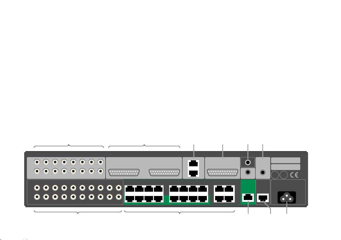
Back panel
The following diagram gives details of the back panel
connections:
Page 10

Meridian 271 Digital Theatre Controller User Guide
5
Audio inputs
Use this input To connect to this
Analogue Input Unbalanced
1–16.
Analogue Input Balanced
1–8 and 9–16 (DB25).
Digital input 1–8 and 9–16. The digital outputs of an AV system,
Digital input 1–16 (DB25) The digital outputs of an AV system,
SpeakerLink Input A Meridian source such as the 218
The unbalanced analogue outputs of
an AVR system, using RCA phono
cables.
The balanced analogue outputs of
an AVR system, using XLR to DB25
cables.
using RJ45 leads.
using an AES DB25 cable.
Zone Controller, using a SpeakerLink
cable.
Audio outputs
Use this output To connect to this
Analogue Output 1–16 and
A–D
Speakerlink Output 1/2 to
15/16, A/B, and C/D
Power amplifiers or active analogue
speakers, using RCA phono cables.
Meridian DSP loudspeakers, using
SpeakerLink cables.
Control signals
Use this connection To connect to this
Ethernet An IP control system.
IR Input A Meridian infra-red eye.
Trigger Input A controller for remote on/off
switching, using a 3.5mm mono jack
plug.
Trigger Output A power amplifier for remote on/off
switching, using a 3.5mm mono jack
plug.
Page 11
6
271 Digital Theatre Controller
Digital AVR
SPEAKERLINK
OUTPUTS
DIGITAL
OUTPUT
DIGITAL
INPUT
RJ45 Leads
12 x Meridian
DSP loudspeakers
Meridian 271 Digital Theatre Controller User Guide
Applications
Digital AVR and Meridian Digital Theatre
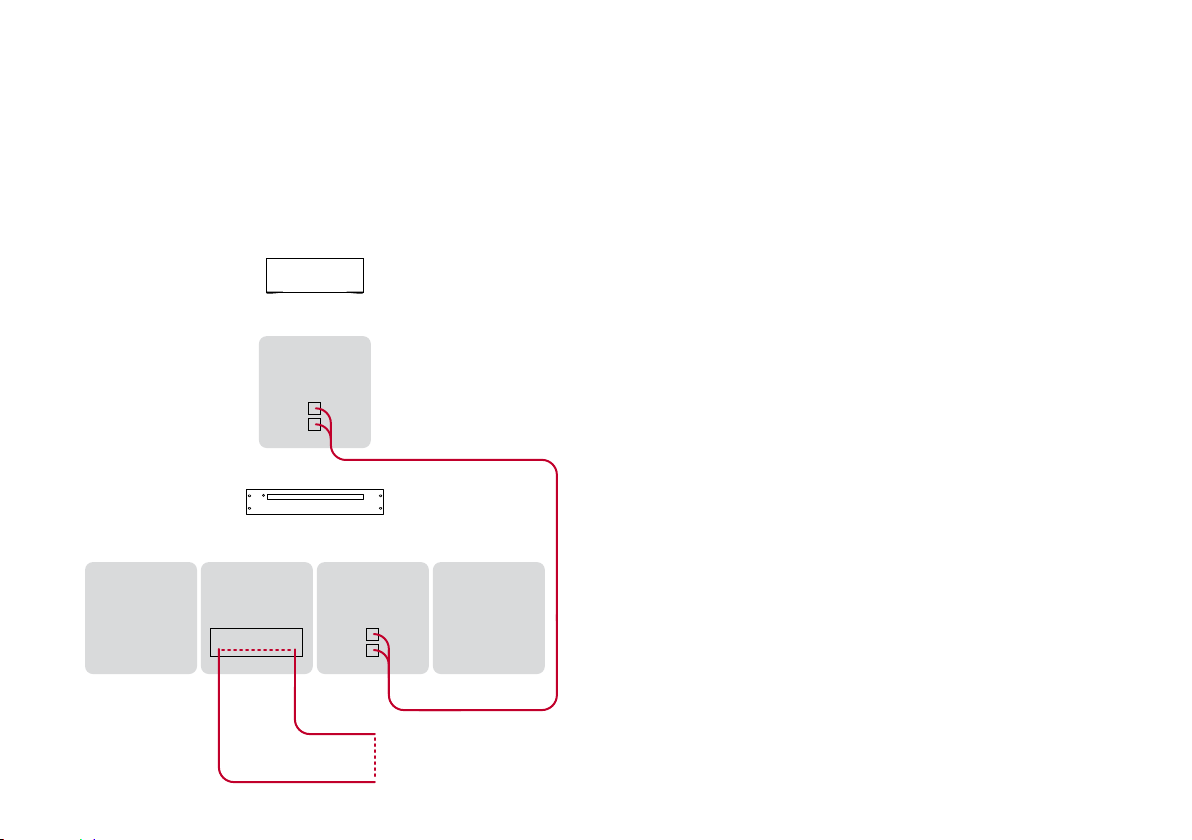
This is a superb 12-channel Meridian Digital Theatre using a
271 in conjunction with a digital AVR system.
Connect the digital outputs from the digital AVR system to the
•
RJ45 Digital Inputs on the 271, using two RJ45 cables.
Connect the Meridian DSP loudspeakers to the SpeakerLink
•
outputs on the 271.
A suggested configuration is:
Front left and right: 2 x Meridian DSP7200.
•
Centre: Meridian DSP7200HC.
•
Subwoofer: Meridian DSW.
•
Sides: 2 x Meridian DSP640.
•
Rears: 2 x Meridian DSP5200.
•
Ceiling: 4 x Meridian DSP320.
•
Page 12
Meridian 271 Digital Theatre Controller User Guide
271 Digital Theatre Controller
Analogue AVR
SPEAKERLINK
OUTPUTS
ANALOGUE
OUTPUT
ANALOGUE
INPUT
UNBALANCED
RCA Phono Leads
8 x Meridian
DSP loudspeakers
7
Analogue AVR and DSP in-wall theatre 7.1
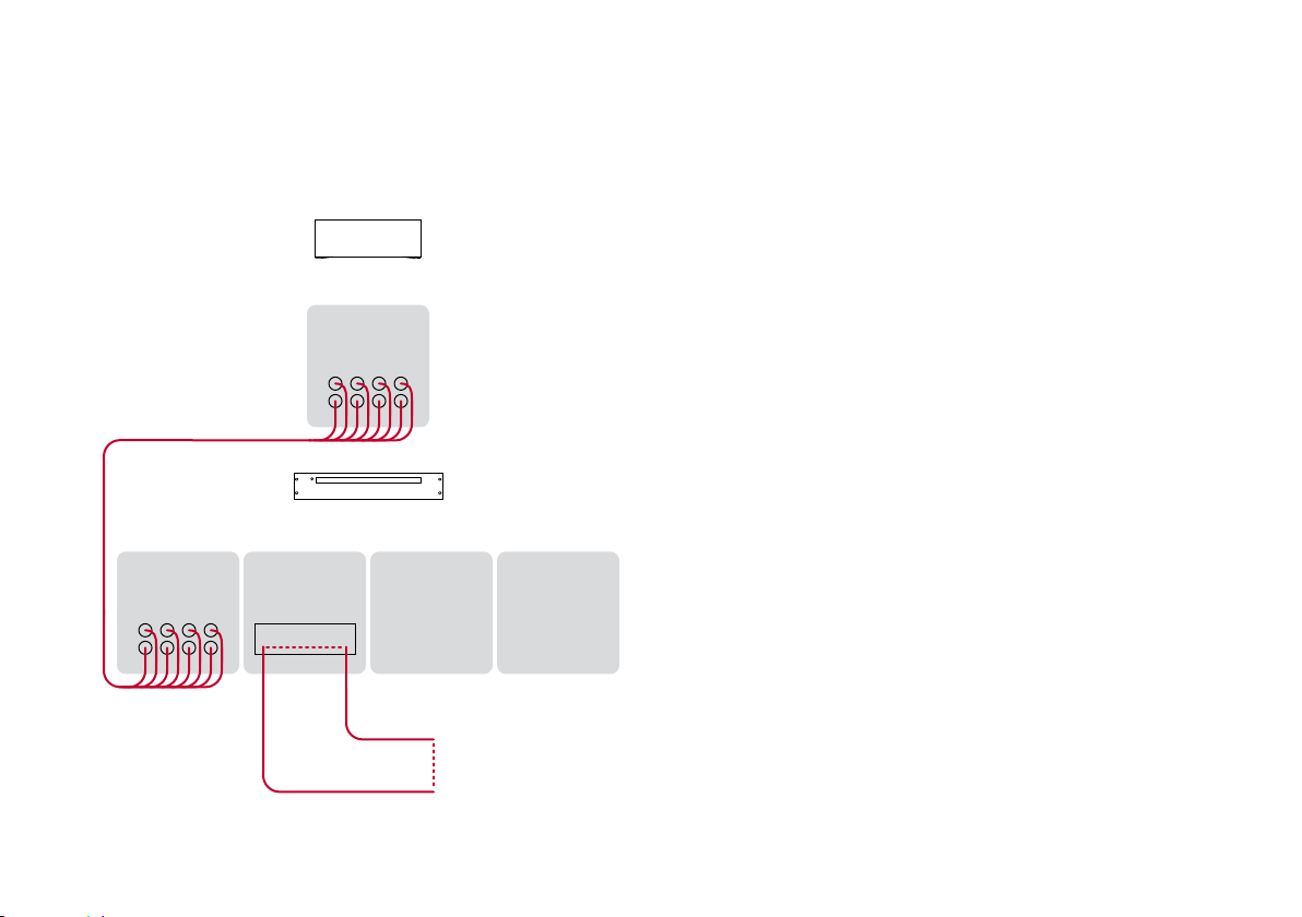
This is a 7.1 system based on a 271 in conjunction with an
analogue AVR system.
Connect the unbalanced analogue outputs from the Analogue
•
AVR system to the unbalanced analogue inputs on the 271,
using eight RCA phono cables.
Connect the Meridian DSP loudspeakers to the SpeakerLink
•
outputs on the 271.
A suggested configuration is:
Front left, right, and centre: 3 x Meridian DSP640.
•
Subwoofer: Meridian DSW.
•
Sides and rears: 4 x Meridian DSP320.
•
Page 13
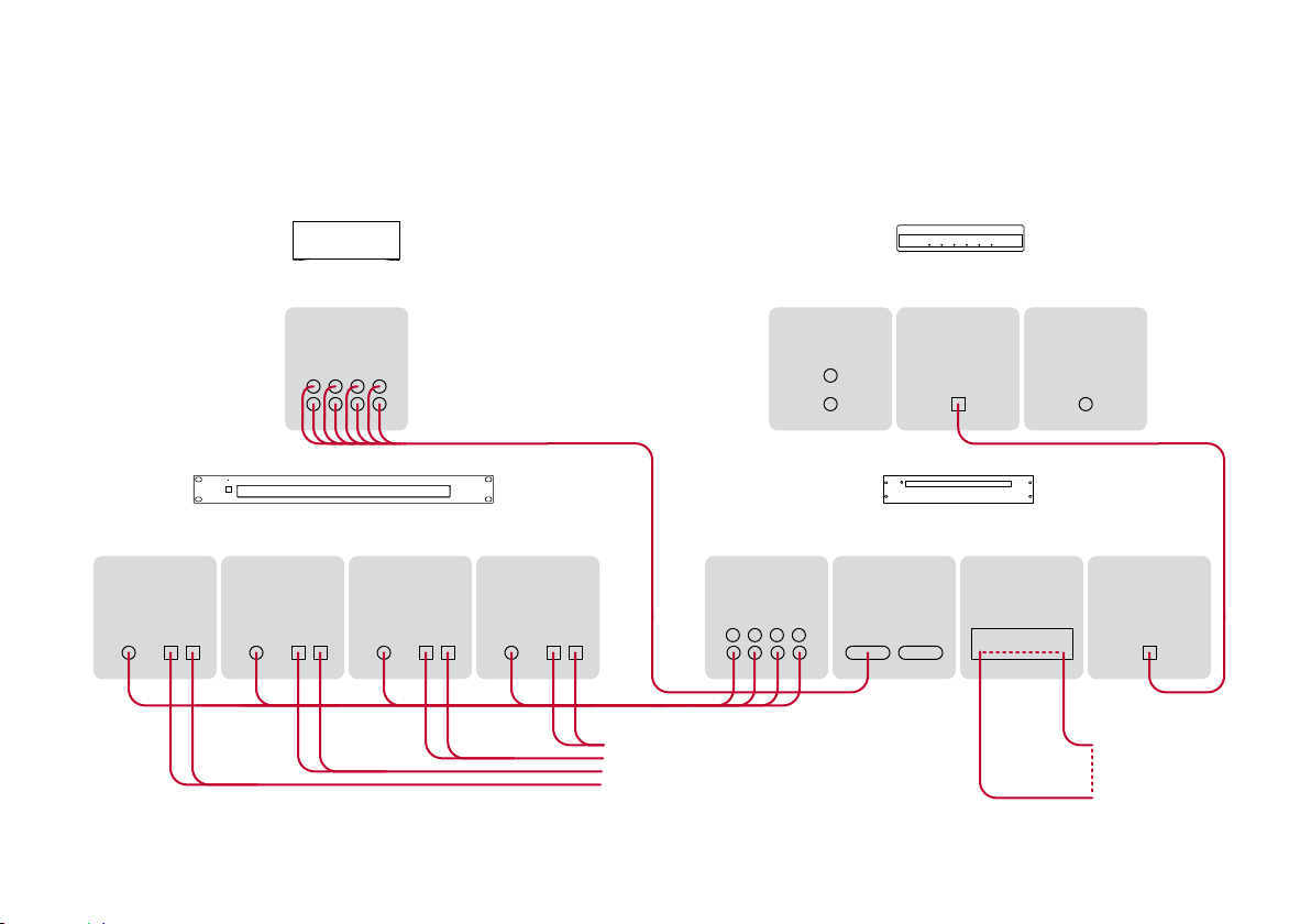
8
271 Digital Theatre Controller
Analogue AVR
SPEAKERLINK
OUTPUTS
ANALOGUE
OUTPUT
BALANCED
ANALOGUE
OUTPUT
ANALOGUE
INPUT
BALANCED
INPUT OUTPUT INPUT OUTPUT INPUT OUTPUT INPUT OUTPUT
Meridian 258 Multi Channel Power Amplifier
ANALOGUE
INPUT
DIGITAL
INPUT
SPEAKERLINK
OUTPUT
218 Zone Controller
XLR to DB25 Lead
4 x Meridian
DSP loudspeakers
4 x Passive
loudspeakers
SPEAKERLINK
INPUT
Meridian 271 Digital Theatre Controller User Guide
Balanced analogue AVR and mixed DSP/analogue theatre 7.1
Page 14

Meridian 271 Digital Theatre Controller User Guide
9
This is a 7.1 system based on a 271 in conjunction with an
AVR system with balanced analogue outputs. It uses Meridian
DSP loudspeakers for the front channels and the subwoofer,
and passive loudspeakers for the side and rear channels; these
are powered by four channels of a Meridian 258 Eight Channel
Amplifier.
In addition, this system uses a Meridian 218 to provide twochannel analogue and digital inputs. The 218 can also be
connected via Ethernet to a Meridian Sooloos system, allowing
access to music in the theatre.
Connect the balanced analogue outputs from the Analogue
•
AVR system to the balanced analogue inputs on the 271,
using a balanced XLR to DB25 cable.
Even though all audio paths through the 271 are equivalent, we
recommend that the main left and right signals are connected
on XLR inputs 1 and 2. This is because the SpeakerLink input
will always be routed to outputs 1 and 2, which should be the
main left and right loudspeakers.
Connect four Meridian DSP loudspeakers to the main (1 and
•
2), centre (3), and subwoofer (4) SpeakerLink outputs on the
271.
Connect analogue outputs 5, 6, 7, and 8 from the 271 to the
•
inputs of four channels on the Meridian 258 Eight Channel
Amplifier.
Connect the outputs from the corresponding channels on the
•
258 to the side and rear passive loudspeakers.
A suggested configuration is:
Front left and right: 3 x Meridian DSP5200.
•
Front centre: Meridian DSP5200HC.
•
Subwoofer: Meridian DSW.
•
Sides and rears: passive loudspeakers.
•
In this mixed system the AVR should be used to change the
bass and treble, since the 271 will not affect these settings
on the analogue outputs. The 271 should be used for volume
adjustments and specific DSP loudspeaker features such as
Centre Elevation.
If you are using an Ethernet-based automation system, for best
results connect it to the Network socket on the 271 (rather
than the 218).
Page 15

10
Meridian 271 Digital Theatre Controller User Guide
Configuring the 271 Digital Theatre Controller
The 271 contains a built-in web interface, allowing it to be
configured via the Ethernet connection using a standard web
browser.
Displaying the 271 configuration page
To display the 271 configuration page
Connect the 271 to a network.
•
Identify the IP address assigned to the 271 (see below).
•
Type this address into the address bar of a standard web
•
browser running on a computer or tablet on the same
network.
You should then see the Meridian 271 configuration
page. This allows you to see or change the 271 settings, or
reset them to their defaults, and also gives access to an online
version of this user guide.
Full details of each of the groups of settings are given in the
following sections.
To store the settings
After changing any settings click the Store Settings button
below the settings panels.
Restoring settings
Click the menu button at top left of the Meridian 271
•
configuration page.
Click Restore Settings.
•
For more information see
Restore Settings
, page 17.
Discovering the IP address of the 271
To discover the IP address of the 271 you can use any of the
following methods:
The IP Control app (see
•
automatically discover the 271 and link directly to the 271
configuration page.
On a Touch:PC it can be found using the Device Manager.
•
Log in to the network router and view the list of attached
•
devices.
Use a network IP scanner to ‘ping’ a list of addresses on the
•
network.
IP Control app
, page 18) will
Page 16

Meridian 271 Digital Theatre Controller User Guide
11
Identification
Identifies the product software version, network MAC address,
and Zone Name.
Source configuration
Allows you to configure the 12 Meridian sources.
Legend: A string of up to 5 characters which will be displayed on the Automation interface, and on DSP loudspeakers.
Page 17

12
Meridian 271 Digital Theatre Controller User Guide
Audio input: Each of the 12 logical sources can be assigned to any of the audio inputs: Analogue–RCA, Analogue– DB25, Digital–RJ45, Digital–DB25, or SpeakerLink. Alternatively any source can be set to Last Valid, which changes the other settings but leaves the input unchanged, or
Off, which makes the source unavailable.
Trigger: Can be set to On, Off, or LV (Last Valid) to control
the trigger output. Note that the trigger is always off in standby.
Validity: Some sources, such as the Meridian CD players, use the Validity flag in the S/PDIF audio stream to indicate that the audio should not be played. Setting this may reduce unwanted noises in some situations.
Comms Type: For Comms-connected systems, ensures that
the appropriate set of commands is sent to the product. The
following categories are available:
1C = CD player, 2C = Radio, 3C = DVD player, 4C = Sooloos
All others should be set to NC (No Comms).
Address: If there are two or more products of each type then the address should be 1A for the first, 2A for the second, etc.
Startup
Start volume: Specifies the initial volume for the outputs. The start volume is set when the 271 is first powered up, and a few seconds after going into standby.
By default the 271, and the DSP loudspeakers, start at volume
65 and retain the last volume setting when they enter or leave
standby.
Startup source: Specifies the source that the 271 will start with if the user has a Source key on their chosen user interface. This will also be the source that is selected when the user presses the front panel button.
State after power up: Specifies whether the 271 should start in Standby or On when powered up.
Page 18

Meridian 271 Digital Theatre Controller User Guide
13
Channel duplication
Allows you to specify which pair of channels 1/2 to 15/16
are duplicated to the analogue outputs A/B and C/D, and the
digital outputs A/B and C/D.
For the analogue channels you can also specify that the output
pair should be: left and right (ie as they were input), both left, or
both right, allowing multiple duplication of individual channels.
To achieve the same multiple duplications of digital outputs,
configure individual DSP loudspeakers as left or right in order to
select which of the pair to play back.
Audio menus
The options on the Audio menus page allow you to specify
the default values of settings on DSP loudspeakers when
Page 19

14
Meridian 271 Digital Theatre Controller User Guide
the 271 is powered up, and change the settings when the
loudspeakers are being used.
Enable SpeakerLink: Specifies whether the SpeakerLink output is on or off.
Treble, Bass, Balance, and Axis
These settings can be controlled either by SpeakerLink or
by Meridian Comms. The default values can only be set via
SpeakerLink. To use these controls via SpeakerLink the
Enable SpeakerLink option should be set to On.
These settings do not affect the analogue outputs, so in a
mixed analogue/digital theatre you should use the adjustments
available on the AVR.
Treble: Tilts the frequency of the response over the entire frequency range to make the sound brighter or dimmer. It can be adjusted between ±10db in 0.5dB steps.
Bass: Adjusts the bass response in the room by ±5dB in
0.5dB steps.
Balance: Compensates for an off-centre listening position where 0 is central, 8 is in line with the corresponding main speaker, and 10 is fully to one side.
Axis: Allows you to adjust the optimum listening height of the loudspeakers, like a balance control operating in the vertical plane.
SpeakerLink controls
These controls only affect DSP loudspeakers connected via
SpeakerLink. To use them the Enable SpeakerLink option
should be set to On.
The effect of these options depends on the capabilities of the
DSP loudspeakers in the system; see the individual loudspeaker
user guide for more information.
Enhanced Bass Alignment: improves the bass alignment in DSP loudspeakers that support it. Note that the extra processing adds a time delay, so it may need to be disabled for video sources.
Loudness: Alters the loudspeaker response for listening at low volume levels.
Measurement units: Changes the units used for specifying the room height: Inches for inches, or Metric for cm.
Subwoofer Gain: Allows you to adjust the gain of the subwoofer(s) by from -15dB to +15dB.
Centre Elevation: Can be set to Max, Med, or Min to raise the image projected by the centre speaker. This creates a much more involving movie experience, with superior image integration across the whole width of the audio presentation.
Page 20

Meridian 271 Digital Theatre Controller User Guide
15
Enhanced Boundary Control: Compensates for reflective
room surfaces. Choose between Off (unreflective), Min, Med,
or Max (highly reflective).
Room height: Used for Enhanced Boundary Control calculations in loudspeakers with downward-firing drive units, such as the M6 or DSW, to compensate for reflections with the room ceiling. Can be varied between 150cm (58in) and 400cm (158in) in steps of 5cm (2in). If the room height is outside this range set the nearest available value.
Comms
Master speaker: Specifies which pair of loudspeakers are the Master speakers. These should be Meridian DSP loudspeakers.
System Address: If an installation contains multiple zones that are connected together with Meridian Comms, each one needs a different System Address if they are to have independent source selection and volume controls. If the
Page 21

16
Meridian 271 Digital Theatre Controller User Guide
installation uses LAN connections then this can be left at its
default, 1A.
Product Address: If there are two or more Meridian sources in the same category on the same Comms-connected system then each unit must have a different Product Address. The setting does not apply to IP connected systems and should be left at its default, 1A.
Trigger input: Specifies how the 271 Trigger Input controls the 271: Ignore, On only, or On and Off.
IR mode: The IR mode is only relevant if a G12 has been connected to the 271. In this setup the installer should set the mode to Controller to ensure that the unit functions as the system controller.
IR receiver is currently: Shows the state of the IR receiver.
Ethernet
Allows you to change the Ethernet configuration. Note that
incorrect settings may make the 271 unreachable via the web
page.
Page 22

Meridian 271 Digital Theatre Controller User Guide
17
Restore Settings
Allows you to restore one or more groups of settings to their
factory defaults. Note that restoring the Ethernet settings will
enable DHCP, which may change the IP address of the 271,
and you may have to find the new address as described below.
Select the checkboxes corresponding to the settings you
•
want to restore.
Click Reset Selected at the bottom of the page.
•
Zone Name: This is used by the Automation Interface to identify the unit. The factory default uses a combination of the product name and MAC address.
Audio output: Returns the A/B & C/D channel duplications to their defaults.
Audio menus: Resets the settings on the Audio menus page.
Source configuration: Restores the source legends, their associated audio inputs and Comms configurations; see
configuration
Comms and startup choices: Returns the startup state to standby and volume to last valid.
Ethernet configuration: Removes any static IP selection and re-enables DHCP. If this box is ticked then the unit will begin the process of getting a new IP address automatically. It may be given a new address by the DHCP server, in which case you will have to find the new address; see
IP address of the 271
, page 11.
Discovering the
, page 10.
Source
Page 23
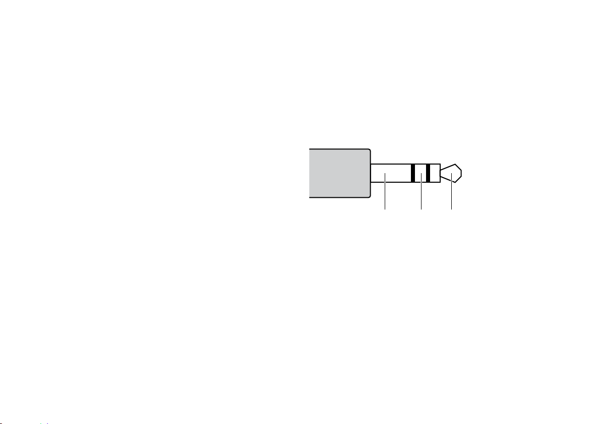
18
+12VIR signalGround
Meridian 271 Digital Theatre Controller User Guide
Controlling the 271 Digital Theatre Controller
The Meridian 271 can be controlled using the following options:
Via Meridian Comms from another product such as a Meridian
•
CD Player.
Via the Ethernet connection using the Automation Interface.
•
Via Infra Red, using the optional G12 remote IR sensor and
•
either the MSR, MSR+, or AC200 remote controls.
IP Control app
Meridian provide a free app for iOS called IP Control that
uses the Automation Interface of the 271. Search for Meridian
in the Apple App Store to download it.
Ethernet connection
A LAN connection is required to configure the 271 Powered
Zone Controller. Also, various aspects of the update and
support systems require that the LAN allows Link Local
addressing and multicast transmission as well as UDP and TCP
traffic. Simple unmanaged switches will always pass this traffic
but Wireless Access Points should be selected carefully and
managed switches must be configured correctly to pass this
traffic.
Third-party IR inputs
The Meridian G12 IR sensor has the following pinout:
Third-party IR receivers with the same pinout may be compatible
but their operation is not guaranteed.
Many home automation/control systems feature outputs
suitable for feeding IR emitter devices (also referred to as “IR
blasters”). These signals differ from those derived from infra–red
receivers in that they are modulated with a carrier frequency.
The 271 will automatically detect this and extract the underlying
IR signal. Use only the Ring and Sleeve connections for these
devices; the Tip (12V) should be left unconnected.
For details of the Automation Interface and the IR control codes
see the Meridian website:
www.meridian-audio.com
Page 24
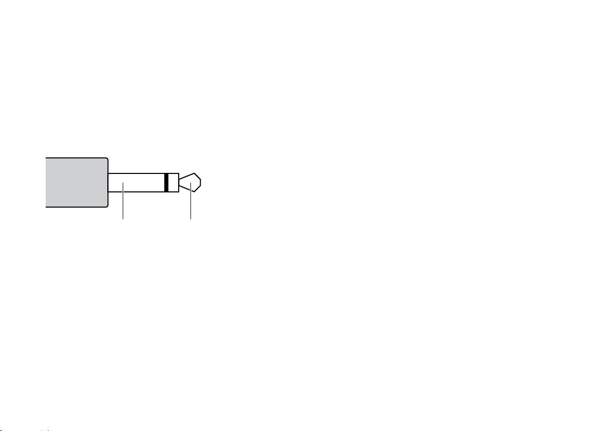
Meridian 271 Digital Theatre Controller User Guide
+12VGround
19
Trigger input and output
The trigger input and output are both designed to use mono
3.5mm jack plugs. The input circuitry is optically coupled, so
works for either polarity of signal across tip and ring. The output
presents a +12V signal on tip and ground on ring:
Trigger input
By default the 271 will respond to rising or falling edges on the
trigger to mean on and off respectively. The product will leave
and enter standby in the same manner as if the front panel
button has been pressed.
Trigger output
Each logical source has a configurable trigger setting, when
that source is selected the trigger level will either:
Turn on
•
Remain at the current level (Last Valid)
•
Turn off
•
The trigger will always go off when the product is in standby.
Page 25

20
Meridian 271 Digital Theatre Controller User Guide
Index
A
Address option 12
Analogue AVR and DSP in-wall theatre
7.1 7
analogue inputs 5
analogue outputs 5
applications
Analogue AVR and DSP in-wall theatre
7.1 7
Balanced analogue AVR and mixed
DSP/analogue theatre 7.1 8
Digital AVR and Meridian Digital Theatre
6
Audio input option 12
Audio menus panel 13
Automation Interface 18
auxiliary output 4
Axis option 14
B
back panel connections 4
Balanced analogue AVR and mixed DSP/
analogue theatre 7.1 8
Balance option 14
Bass option 14
C
Centre Elevation option 14
Channel duplication panel 13
Comms panel 15
Comms Type option 12
communications connections 5
configuration 10
configuration page 10
controlling 18
D
Digital AVR and Meridian Digital Theatre 6
digital inputs 5
E
Enable SpeakerLink option 14
Enhanced Bass Alignment control 14
Enhanced Boundary Control option 15
Ethernet connection 5, 18
Ethernet panel 16
I
Identification panel 11
inputs 5
IP Control application 18
IR input 5
IR mode option 16
IR receiver is currently option 16
IR sensor pinout 18
Page 26

L
Legend option 11
loudspeaker outputs 4
M
Master speaker option 15
Measurement units option 14
O
optical input 5
outputs 5
P
panels
Audio menus 13
Channel duplication 13
Comms 15
Ethernet 15
Identification 11
Restore Settings 17
Meridian 271 Digital Theatre Controller User Guide
panels
(continued)
Source configuration 11
Startup 12
Phono output option 13
Product Address option 16
R
registration iv
Restore Settings panel 17
restoring settings 10
Room height option 15
S
safety warnings iii
Source configuration panel 11
SpeakerLink controls 14
Centre Elevation 14
Enhanced Bass Alignment 14
Enhanced Boundary Control 15
Loudness 14
Room height 15
Subwoofer Gain 14
21
SpeakerLink input 5
SpeakerLink outputs 5
specifications 3
Startup panel 12
Startup source option 12
Start volume option 12
State after power up option 12
storing settings 10
Sub Gain option 14
System Address option 15
T
Treble option 14
trigger input 5, 19
Trigger input option 16
Trigger option 12
trigger output 5, 19
V
Validity option 12
 Loading...