

Page 1
IPP
IPS
OPERATING
INSTRUCTIONS
PELTIER-COOLED INCUBATOR IPP
STORAGE COOLED INCUBATOR IPS
100% ATMOSAFE. MADE IN GERMANY.
www.memmert.com | www.atmosafe.net
Page 2

Manufacturer and customer service
MEMMERT GmbH + Co. KG
Postfach 17 20
91107 Schwabach, Germany
Äußere Rittersbacherstr. 38
91126 Schwabach
Germany
Phone: +49 (0)9122 925-0
Fax: +49 (0)9122 14585
E-mail: sales@memmert.com
Internet: www.memmert.com
Customer service:
Service hotline: +49 (0)9171 9792 911
Service fax: +49 (0)9171 9792 979
E-mail: service@memmert.com
When contacting customer service, always quote the product serial number on the nameplate
(see page 12 ).
Shipping address for repairs:
Memmert GmbH + Co. KG
K
undenservice
Willi-Memmert-Str
DE-91186 Büchenbach
Germany
Please contact our customer service before sending appliances for repair or before returning
equipment, otherwise, we have to refuse acceptance of the shipment.
© 2012 MEMMERT GmbH + Co. KG
Date 09/2012
We reserve the right to make changes
. 90-96
Page 3

About this manual
About this manual
Purpose and target group
This manual describes the assembly, function, transport and operation of Peltier incubators IPP and cooled storage incubators IPS. It is intended for use by trained personnel of
the owner, who have the task of operating and/or maintaining the respective appliance.
If you are asked to work on the appliance, read this manual carefully before starting. Familiarise yourself with the safety regulations. Only perform work that is described in this
manual. If there is something you do not understand, or certain information is missing,
ask your superior or contact the manufacturer. Do not do anything without authorisation.
Versions
The appliances are available in different configurations and sizes. If specific equipment
features or functions are available only for certain configurations, this is indicated at the
relevant points in this manual.
Due to individual configurations and sizes, illustrations in this manual may be slightly different from the actual appearance. Function and operation are identical.
Other documents that have to be observed:
► For operation of the appliance with MEMMERT AtmoCONTROL, observe the separate
software manual
► For service and repair work (see page 38), observe the separate service manual
Storage and resale
This instruction manual belongs with the appliance and should always be stored where
persons working on the appliance have access to it. It is the responsibility of the owner
to ensure that persons who are working or will work on the appliance are informed as to
the whereabouts of this instruction manual. We recommend that it is always stored in a
protected location close to the appliance. Make sure that the instruction manual is not
damaged by heat or humidity. If the appliance is sold on or transported and then set up
again at a different location, the operating instructions must go with it.
3
Page 4

Contents
Contents
1. Safety regulations 6
1.1 Terms and signs used........................................................................................................... 6
1.1.1 Terms used ........................................................................................................................ 6
1.1.2 Signs used ......................................................................................................................... 6
1.2 Product safety and dangers ................................................................................................ 7
1.3 Requirements of the operating personnel .......................................................................... 7
1.4 Responsibility of the owner ................................................................................................. 8
1.5 Intended use ........................................................................................................................ 8
1.6 Changes and conversions ....................................................................................................8
1.7 Behaviour in case of malfunctions and irregularities .......................................................... 9
1.8 Switching off the appliance in an emergency ....................................................................9
2. Construction and description 10
2.1 Construction ...................................................................................................................... 10
2.2 Description .........................................................................................................................11
2.3 Material.............................................................................................................................. 11
2.4 Electrical equipment .......................................................................................................... 11
2.5 Connections and interfaces ............................................................................................... 11
2.5.1 Electrical connection .......................................................................................................11
2.5.2 Ethernet interface............................................................................................................12
2.6 Designation (nameplate) ................................................................................................... 12
2.7 Technical data .................................................................................................................... 13
2.8 Ambient conditions ........................................................................................................... 14
2.9 Scope of delivery ...............................................................................................................14
2.10 Optional accessories ..........................................................................................................14
3. Delivery, transport and setting up 15
3.1 Safety regulations ..............................................................................................................15
3.2 Delivery ..............................................................................................................................15
3.3 Transport ............................................................................................................................ 15
3.4 Unpacking .........................................................................................................................15
3.4.1 Checking for completeness and transport damage ....................................................... 15
3.4.2 Disposing of packaging material .................................................................................... 15
3.5 Storage after delivery ........................................................................................................16
3.6 Setting up .......................................................................................................................... 16
3.6.1 Installation options ......................................................................................................... 17
4. Putting into operation 18
4.1 Connecting the appliance .................................................................................................18
4.2 Switching on ......................................................................................................................18
5. Operation and control 19
5.1 Operating personnel.......................................................................................................... 19
5.2 Opening the door .............................................................................................................. 19
5.3 Loading the appliance .......................................................................................................19
5.4 Operating the appliance .................................................................................................... 20
5.4.1 ControlCOCKPIT .............................................................................................................. 20
5.4.2 Basic operation ................................................................................................................21
5.4.3 Adjustment options ........................................................................................................21
5.4.4 Timer operation ...............................................................................................................22
4
Page 5

Contents
5.5 Temperature monitoring ..................................................................................................23
5.5.1 Electronic temperature monitoring ............................................................................... 23
5.5.2 Mechanical temperature monitoring: Temperature limiter (TB) .....................................23
5.5.3 Function .......................................................................................................................... 24
5.6 Ending operation ............................................................................................................... 24
6. Malfunctions, warning and error messages 25
6.1 Warning messages of the monitoring function ................................................................ 25
6.2 Malfunctions, operating problems and appliance errors ................................................26
6.3 Power failure ...................................................................................................................... 26
7. Menu mode 27
7.1 Overview ............................................................................................................................ 27
7.2 Basic operation in menu mode using the example of language selection ....................... 28
7.3 Setup.................................................................................................................................. 29
7.3.1 IP address ........................................................................................................................ 29
7.3.2 Unit 30
7.3.3 Temperature monitoring (
7.3.4 Timer mode .....................................................................................................................32
7.3.5 Balance (only for model sizes 260 and 750) ...................................................................33
7.4 Date and time ................................................................................................................... 34
7.5 Adjustment ........................................................................................................................ 35
Alarm Temp) .......................................................................31
8. Maintenance and service 38
8.1 Cleaning .............................................................................................................................38
8.1.1 Working chamber and metal surfaces ............................................................................ 38
8.1.2 Plastic parts ..................................................................................................................... 38
8.1.3 Glass surfaces ..................................................................................................................38
8.1.4 Peltier cooling module .................................................................................................... 38
8.2 Regular maintenance.........................................................................................................39
8.3 Repairs and service ............................................................................................................39
9. Storage and disposal 40
9.1 Storage ..............................................................................................................................40
9.2 Disposal .............................................................................................................................40
Index 41
5
Page 6
Safety regulations
1. Safety regulations
1.1 Terms and signs used
In this manual, certain common terms and signs are used to warn you of danger or
to give you hints that are important in avoiding injury or damage. Observe and follow
these hints and regulations to avoid accidents and damage. These terms and signs are
explained below.
1.1.1 Terms used
"Warning"
"Caution"
is used whenever you or somebody else could be injured if you do not
observe the accompanying safety regulation.
is used for information that is important for avoiding damage.
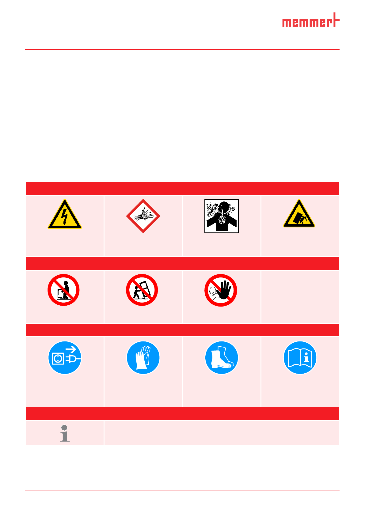
1.1.2 Signs used
Warning signs (warning of a danger)
Danger of electro-
cution
Danger of explosion Dangerous gases /
Prohibition signs (forbidding an action)
vapours
Danger of toppling
over
Do not lift Do not tilt Do not enter
Regulation signs (stipulating an action)
Disconnect the
mains plug
Wear gloves Wear safety boots Observe informa-
Other icons
Important or useful additional information
tion in separate
manual
6
Page 7

Safety regulations
1.2 Product safety and dangers
The appliances described in this manual are technically sophisticated, manufactured
using high-quality materials and subject to many hours of testing in the factory. They
contain the latest technology and comply with recognised technical safety regulations.
However, there are still risks involved, even when the appliances are used as intended.
These are described below.
Warning!
After removing covers, live parts may be exposed. You may receive
an electric shock if you touch these parts. Disconnect the mains plug
before removing any covers. Only electrical technicians may work on
the electrical equipment of the appliances.
Warning!
When loading the appliance with an unsuitable load, poisonous or
explosive vapours or gases may be produced. This could cause the
appliance to explode, and persons could be severely injured or poisoned. The appliance may only be loaded with materials/test objects
which do not form any toxic or explosive vapours when heated up
(see also chapter “Intended use” on page 8).
Warning!
In case of appliances of a certain size, you can get accidentally
locked in, which is life-threatening. Do not climb into the appliance!
1.3 Requirements of the operating personnel
The appliance may only be operated and maintained by persons who are of legal age and
have been instructed accordingly. Personnel who are to be trained, instructed or who
are undergoing general training may only work with the appliance under the continuous
supervision of an experienced person.
Repairs may only be performed by qualified electricians. The regulations in the separate
service manual must be observed.
7
Page 8

Safety regulations
1.4 Responsibility of the owner
The owner of the appliance
► is responsible for the flawless condition of the appliance and for it being operated in
accordance with its intended use (see page 8);
► is responsible for ensuring that persons who are to operate or service the appliance
are qualified to do this, have been instructed accordingly and are familiar with the
operating instructions at hand;
► must know about the applicable guidelines, requirements and operational safety
regulations, and train staff accordingly;
► is responsible for ensuring that unauthorised persons have no access to the appli-
ance;
► is responsible for ensuring that the maintenance plan is adhered to and that mainte-
nance work is carried out properly (see page 38);
► has to ensure that the appliance and its surroundings are kept clean and tidy, for
example through corresponding instructions and inspections;
► is responsible for ensuring that personal protective clothing is worn by operating
personnel, e.g. work clothes, safety shoes and protective gloves.
1.5 Intended use
► Peltier-cooled incubators IPP are intended for the storage of substances and samples,
for determination of life expectancy as well as for cultivation and incubation in a
temperature range of 0 to 70 °C.
► Cooled storage incubators IPS are intended for the storage and cooling of substances
and samples and for determination of life expectancy at constant temperatures in a
range of 14 to 45 °C.
Any other use could be dangerous.
The appliance is not explosion-proof (does not comply with the German workplace
health & safety regulation VBG 24). The appliance may only be loaded with materials and
substances which cannot form any toxic or explosive vapours at the set temperature and
which cannot explode, burst or ignite.
The appliance may not be used for drying, vaporising and branding paints or similar
materials the solvents of which could form an explosive mixture when combined with air.
If there is any doubt as to the composition of materials, they must not be loaded into the
appliance. Potentially explosive gas-air mixtures must not form, neither in the working
chamber nor in the direct vicinity of the appliance.
1.6 Changes and conversions
No unauthorised changes or alterations may be made to the appliance. No parts may be
added or inserted which have not been approved by the manufacturer.
Unauthorised changes or alterations result in the CE declaration of conformity losing its
validity, and the appliance may no longer be operated.
The manufacturer is not liable for any damage, danger or injuries that result from
unauthorised changes or alterations, or from non-observance of the regulations in this
manual.
8
Page 9
Safety regulations
ONN
1.7 Behaviour in case of malfunctions and irregularities
The appliance may only be used in a flawless condition. If you as the operator notice irregularities, malfunctions or damage, immediately take the appliance out of service and
inform your superior.
You can find information on eliminating malfunctions from page 25.
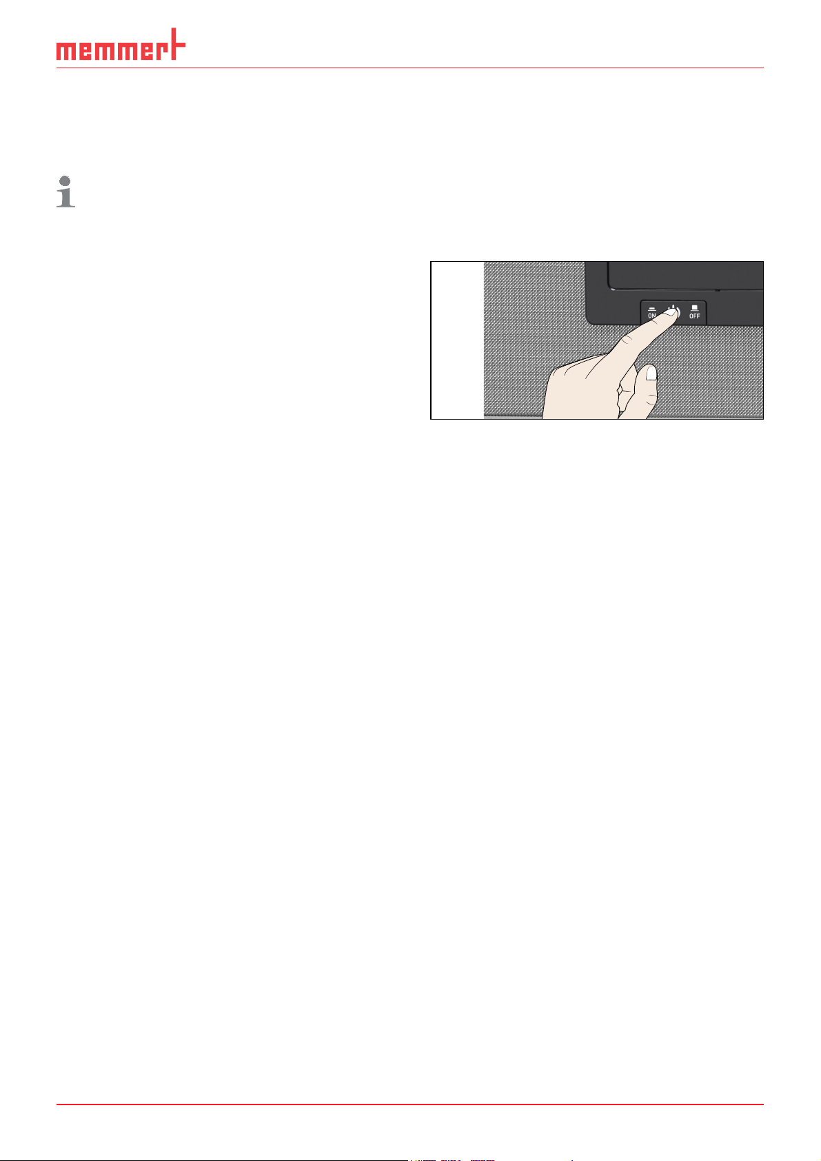
1.8 Switching off the appliance in an emergency
Press the main switch at the ControlCOCKPIT
(Fig. 1). This disconnects the appliance from
the power supply at all poles.
Fig. 1
Switch off the appliance by pressing the
main switch
ON
9
Page 10

Construction and description
2. Construction and description
2.1 Construction
TEMP
°C22.4
1
°CSet 37.0
LICHT
TIMER
30m04h
100
23.Nov 13:30
%
Ende
2
8
1
3
7
4 5 6
Fig. 2 Construction
1 ControlCOCKPIT with capacitive function
keys and LCD displays (see page 20)
2 On/Off switch (see page 18)
3 Chamber fan
4 Steel grid
10
5 Interior
6 Nameplate (see page 12)
7 Door handle (see page 19)
8 Turn control with confirmation key
Page 11

Construction and description
2.2 Description
The appliance can heat the working chamber up to 70 °C (IPP) or 45 °C (IPS) and cool it
down to 0 ºC (IPP) or 14 °C (IPS). Low-noise, long-life and energy-saving Peltier cooling
and heating technology is used for this. In heating operation, a part of the required energy is extracted from the surroundings (heat pump principle). Condensation formation
during the cooling down process takes place outside the working chamber on the Peltier
element
Optionally, the appliance can be equipped with a light module.
2.3 Material
For the outer housing, MEMMERT deploys stainless steel (Mat.No. 1.4016 – ASTM 430)
and for the interior, stainless steel (Mat.No. 1.4301 – ASTM 304) is used, which stands
out through its high stability, optimal hygienic properties and corrosion resistance to
many (but not all!) chemical compounds (caution for example with chlorine compounds).
The chamber load for the appliance must be carefully checked for chemical compatibility with the materials mentioned. A material resistance table can be requested from the
manufacturer.
2.4 Electrical equipment
► Operating voltage and current consumption: See nameplate
► Protection class 1, i.e. operating insulation with PE conductor in accordance with EN
61010
► Protection type IP 20 acc. to EN 60 529
► Interference suppression acc. to EN 55011 class B
► Appliance fuse: Safety fuse 250 V/15 A, quick-blow
► The temperature controller is protected with a miniature fuse 100 mA (200 mA at
115 V)
2.5 Connections and interfaces
2.5.1 Electrical connection
This appliance is intended for operation on an electrical power system with a system
impedance Z
operator must ensure that the appliance is operated only on an electrical power system
that meets these requirements. If necessary, you can ask your local energy supply company what the system impedance is.
Observe the country-specific regulations when connecting (e.g. in Germany
DIN VDE 0100 with residual current circuit breaker).
of a maximum of 0.292 ohm at the point of transfer (service line). The
max
11
Page 12

Construction and description
2.5.2 Ethernet interface
Via Ethernet interface, the appliance can be
connected to a network to read out protocol
logs with the AtmoCONTROL software. The
Ethernet interface is located on the rear of
the appliance (Fig. 3).
For identification purposes, each appliance
connected must have its own unique IP address. Setting the IP address is described on
page 29 .
With an optional USB to Ethernet converter,
the appliance can be directly connected to
a computer / laptop (see “Optional accessories” on page 14).
Fig. 3 Ethernet interface
2.6 Designation (nameplate)
The nameplate (Fig. 4) provides information about the appliance model, manufacturer
and technical data. It is attached to the front of the appliance, on the right behind the
door (see page 10).
1
2
3
4
5
6
Fig. 4 Nameplate (example)
1 Type designation
2 Operating voltage
3 Applicable standard
4 Protection type
5 CE conformity
Typ: IPP 260 F.-Nr.: 0109.0088
230 V
~
DIN12880-Kl.3.1 Nenntemp.: 70 °C
2.3 A 50/60 Hz 525 W
6 Address of manufacturer
7 Disposal note
8 Nominal temperature:
9 Connection / power ratings
10 Appliance number
10
9
8
7
12
Page 13

Construction and description
2.7 Technical data
Appliance IPP IPS
Appliance size 30 55 110 260 750 260 750
Appliance width D1 [mm] 585 585 745 824 1224 824 1224
1
Appliance height E
Appliance depth G
Depth of door lock [mm] 56
Appliance depth F
dle) [mm]
Chamber width A
Chamber height B
Chamber depth C
Chamber volume [litres] 32 53 108 256 749 256 749
Weight [kg] 42 53 84 115 211 110 193
Power [W] 214 240 350 525 1050 350 350
Current consumption [A] 1.0 1.1 1.6 2.3 4.6 1.6 1.6
max. number of sliding shelves 3 4 5 9 14 9 14
max. load per sliding shelve [kg] 30
max. load per appliance [kg] 60 80 100 180 280 180 280
Temperature
1
see Fig. 5
2
With the interior lighting on, the minimum temperature might not be reached.
[mm] 707 787 867 1186 1726 1186 1726
1
(footprint) [mm] 524 604 674 774 874 774 874
1
(including door han-
1
[mm] 400 400 560 640 1040 640 1040
1
[mm] 320 400 480 800 1200 800 1200
1
[mm] 250 330 400 500 600 500 600
Adjustment range 0 to 70 °C
580 660 730 830 930 830 930
2
14 to 45 °C
Adjustment precision 0.1 K
2
D
TEMP
°C22.4
°CSet 37.0
LICHT
TIMER
30m04h
%100
Ende
23.Nov 13:30
F
C
E
B
90
56
A
G
Fig. 5 Dimensions
13
Page 14

Construction and description
2.8 Ambient conditions
► The appliance may only be used in enclosed areas and under the following ambient
conditions:
Ambient temperature
Humidity rh max. 70 %, non-condensing
Overvoltage category II
Pollution degree 2
Altitude of installation max. 2,000 m above sea level
16 ºC to 28 ºC
► The appliance may not be used in areas where there is a risk of explosion. The ambi-
ent air must not contain any explosive dusts, gases, vapours or gas-air mixtures. The
appliance is not explosion-proof.
► Heavy dust production or aggressive vapours in the vicinity of the appliance could
lead to sedimentation in the interior and, as a consequence, could result in short
circuits or damage to electrical parts. For this reason, sufficient measures to prevent
large clouds of dust or aggressive vapours from developing should be taken.
2.9 Scope of delivery
► Power cable
► Sliding grid (load capacity 30 kg each)
► The operating instructions at hand
► Calibration certificate
► For certain appliance sizes, separately packaged fastening material for wall mounting
(see page 16)
2.10 Optional accessories
► USB to Ethernet converter (Fig. 6). Makes
it possible to connect the appliance's
network interface (see page 12) to the USB
port of a computer / laptop.
► Reinforced, sliding steel grids with a load
capacity of 60 kg each (for appliance size
110 and larger)
Fig. 6 Converter USB to Ethernet
14
Page 15

3. Delivery, transport and setting up
3.1 Safety regulations
Warning!
You may get your hands or feet squashed when transporting and installing the appliance. Wear protective gloves and
safety boots.
Warning!
Because of the heavy weight of the appliance, you could injure
yourself if you try to lift it. To carry appliances of the sizes 30 and
55, at least two persons, for appliances of the sizes 75 and 110, four
persons are needed. Appliances larger than that may not be carried
but must be transported with a manual pallet jack or forklift truck.
30 55 110 260 750
Delivery, transport and setting up
Warning!
The appliance could fall over and seriously injure you. Never tilt the
appliance and transport it in upright position only.
3.2 Delivery
The appliance is packed in cardboard and is delivered on a wooden palette.
3.3 Transport
The appliance can be transported in three ways:
► With a forklift truck; move the forks of the truck entirely under the pallet.
► On a manual pallet jack
► On its own castors, in case of the corresponding configuration, for which the catch
on the (front) castors must be released
3.4 Unpacking
To avoid damage, do not unpack the appliance until you reach the installation site.
Remove the cardboard packaging by pulling it upwards or carefully cutting along an
edge.
3.4.1 Checking for completeness and transport damage
► Check the delivery note to ensure that the delivery is complete.
► Check the appliance for damage.
If you notice deviations from the delivery note, damage or irregularities, do not put the
appliance into operation but inform the haulage company and the manufacturer.
3.4.2 Disposing of packaging material
Dispose of the packaging material (cardboard, wood, foil) in accordance with the applicable disposal regulations for the respective material in your country.
15
Page 16

Delivery, transport and setting up
3.5 Storage after delivery
If the appliance is first to be stored after delivery: Read the storage conditions from page
40.
3.6 Setting up
Warning!
Due to their centre of gravity, appliances of certain sizes can fall over
to the front and injure you or other people. Separately packaged fastening material is included in the scope of delivery of the appliances
concerned. After setting up the appliance, use this fastening material
for mounting the appliance's rear side to a wall. Observe the assembly instructions provided.
The installation site must be flat and horizontal and must be able to reliably bear the
weight of the appliance (see “Technical data“ on page 13). Do not place the appliance on a
flammable surface.
Depending on the model (see nameplate), a 230 V or 115 V power connection must be
available at the installation site.
The distance between the wall and the rear of the appliance must be at least 15 cm. The
clearance from the ceiling must not be less than 20 cm and the side clearance from walls
or nearby appliances must not be less than 5 cm (Fig. 7). Sufficient air circulation in the
vicinity of the appliance must be guaranteed at all times.
FP
FP FP FP
Fig. 7 Minimum clearance from walls and ceiling
16
Page 17

3.6.1 Installation options
Delivery, transport and setting up
Setting up Comments
Floor
Table
Check the load capacity first
Stacked
Two appliances maximum;
mounting material (feet) provided
Wall
mounting
Separately packaged fastening
material is included in the scope
of delivery. Observe the assembly instructions provided.
Suitable for appliance size ...
30 55 110 260 750
Base
Castor
frame
Height adjustable
feet
With/without castors
17
Page 18

Putting into operation
ONN
4. Putting into operation
Caution:
The first time the appliance is operated, it must not be left unattended until it has
reached the steady state.
4.1 Connecting the appliance
Caution:
Observe the country-specific regulations when
making connections (e.g. in Germany DIN VDE 0100
with residual current circuit breaker). Observe the
connection and power ratings (see nameplate and
"Technical Data" on page 13).
Plug the provided power cable into the rear of the ap-
pliance and connect it to the power supply ( Fig. 8 ).
4.2 Switching on
Fig. 8 Connect the power
cable to the rear of the appliance
Switch on the appliance by pressing the main switch on
the front of the appliance ( Fig. 9 ).
If the appliance has never been operated before,
you will be prompted to set the operating lan-
guage, date and time when you first switch it on. A
description of how to do this is given from page 28 .
However, to get a basic overview of operating the
appliance, you should read the following chapter
first.
ON
Fig. 9 Switch on appliance
18
Page 19

Operation and control
5. Operation and control
5.1 Operating personnel
The appliance may only be operated by persons who are of legal age and have been
instructed accordingly. Personnel who are to be trained, instructed or who are undergoing general training may only work with the appliance under the continuous supervision
of an experienced person.
5.2 Opening the door
► To open the door, pull the door handle to the side (to the left or to the right, depend-
ing on the door variation, see Fig. 10 , A. The door opens slightly, so that the heat
can be vented with the door ajar in case of high temperature inside the chamber. The
door can then be opened completely (B).
► To close the door, push the door handle back (C).
A
Fig. 10 Opening and closing the door
Warning!
In case of appliances of a certain size, you can get accidentally
locked in, which is life-threatening. Do not climb into the appliance!
5.3 Loading the appliance
Warning!
When loading the appliance with an unsuitable load, poisonous or
explosive vapours or gases may be produced. This could cause the
appliance to explode, and people could be severely injured or poisoned. The appliance may only be loaded with materials which do
not form any toxic or explosive vapours when heated up and cannot
ignite (see also “Intended use” on page 8). If there is any doubt as to
the composition of materials, they must not be loaded into the appliance.
C
B
Caution:
Check the chamber load for chemical compatibility with the materials of the appliance (see page 11).
19
Page 20

Operation and control
ONN
ONN
ONN
ONN
Insert the sliding steel grids or sliding shelves. The maximum number or grids / shelves
and the load capacity are specified in the technical data overview from page 13 .
The chamber must not be
loaded too tightly, so that
proper air circulation in
the interior is guaranteed.
Do not place any of the
chamber load on the floor,
touching the side walls or
right below the ceiling of
the chamber (Fig. 11, see
also the "correct loading"
sticker on the appliance).
In case of improper loading (chamber loaded too
tightly), reaching the set
temperature may take
Fig. 11 Correct placement of the chamber load
longer than normal.
5.4 Operating the appliance
5.4.1 ControlCOCKPIT
In manual operation, the desired parameters are entered at the ControlCOCKPIT on the
front of the appliance (Fig. 12 and Fig. 13 ). You can also make basic settings here (menu
mode). Additionally, warning messages are displayed, e.g. if the temperature is exceeded.
312
LÜFTER
TEMP
0
°C22.4
TIMER
30m04h
44h:44m
End
23.Nov 13:30
End 14: 45
ON
ON
%
°CSet 37.0
LIGHT
%100
78
ON
ON
9
1045 6
TEMP
180.4°C
Set 180
TIMER
44h:44m
Ende
End 14: 45
TEMP
.4°C
TIMER
30m04h
23.Nov 13:30
LÜFTER
0
°C22.4
%
°CSet 37.0
312
9
1045 6
Fig. 12 ControlCOCKPIT of Peltier-cooled
incubators IPP in operating mode
Fig. 13 ControlCOCKPIT of cooled storage
incubators IPS in operating mode
1 Activation key for temperature setpoint adjustment
2 Setpoint and actual temperature display
3 Switch to menu mode (see page 27)
4 Activation key for timer setting
5 Main switch
6 Timer display
7 Interior lighting display (only for models with light module)
8 Interior lighting activation key (only for models with light module)
9 Turn control for individual setpoint adjustment
10 Confirmation key (accepts setting made with the turn control)
20
Page 21

5.4.2 Basic operation
TIMER
m
h
4
2
T
In general, all settings are made according to the following pattern:
Operation and control
1. Activate the desired parameter (e.g.
temperature). To do so, press the cor-
responding activation key on the left
or right of the respective display. The
activated display is lined in colour, the
other displays are dimmed. The set
value is highlighted in colour.
2. By turning the turn control to the left
or right, adjust the set value (e.g. to
37.0 ºC).
3. Save the set value by pressing the con-
firmation key.
The display returns to normal and the
appliance begins adjusting to the de-
fined set value.
Additional parameters can be set accordingly.
TEMP
TEMP
22.
2
Set
.5°C100
TEMP
TEMP
°C22.4
°C
37.0Set
°C22.4
°CSet 37.0
If no new values are entered or confirmed for approx. 30 seconds, the appliance
automatically restores the former values.
If you want to cancel the setting procedure, press the
activation key on the left or right of the display that you
want to exit. The appliance restores the former values.
Only the settings that you have confirmed by pressing
the confirmation key before cancelling the setting pro-
cedure are accepted.
5.4.3 Adjustment options
As described in chapter 5.4.2 , you can set the following parameters after pressing the
corresponding activation key (in any sequence):
Temperature
Adjustment range: model-dependent (see nameplate and technical data on page 13)
Heating operation is indicated by the
Cooling is indicated by the
symbol.
symbol.
You can select °C or °F as the temperature unit displayed
(see page 20).
TEMP
T
°C22.4
°CSet 37.0
Interior lighting (only for cooled incubators IPP with light
module)
Adjustment range: 0 % (off), 100 % (on)
LIGHT
100
%
21
Page 22

Operation and control
.5 C100
Set
1
5.4.4 Timer operation
In timer operation, you can adjust the time the appliance runs at the set temperature:
1. Press the activation key to the left of
the timer display. The timer display is
activated.
2. Turn the turn control until the desired
duration is displayed – in this exam-
ple 4 hours 30 minutes. The approxi-
mate end time is shown beneath, in a
smaller font.
Up to a duration of 23 hours 59 minutes, the time is displayed in hh:mm
(hours:minutes) format. For 24 hours and more, the format dd:hh (days:hours) is
used. The maximum duration adjustable is 99 days 23 hours.
3. Press the confirmation key to confirm.
The display now shows the remain-
ing time in a large font and the ap-
proximate end time in a smaller font
beneath.
TIMER
04 mh 3
End
TIMER
End
TIMER
0
00h0 m
23.11. 09:00
Ende
0
23.Nov 13:30
30m04h
23.Nov 13:30
4. Now, as described under 5.4.2 , set the temperature you want the appliance to oper-
ate at. The set value can be changed at any time while the timer elapses. The changes
are effective immediately.
In
Setup, you can choose if the timer should run setpoint-dependent or not. This
determines whether the timer should not start until a tolerance band around the set
temperature is reached or if it should start right after activation (see page 32). If the
timer runs setpoint-dependent, this is indicated by the
display.
When the timer has elapsed, the display shows 00:00. Heating
or cooling is switched off.
symbol in the timer
TIMER
00m00h
End
To deactivate the timer, open the timer display by pressing the
activation key again and then turning the turn control to
reduce the timer setting until --:-- is displayed. Confirm with
the confirmation key.
End
23.Nov 13:30
TIMER
--m--h
23.Nov 13:30
22
Page 23

Operation and control
5.5 Temperature monitoring
The appliance is equipped with a double overtemperature protection (mechanical/electronic) in accordance with DIN 12 880. This serves to avoid damage to the chamber load
and/or appliance in case of a malfunction:
► Electronic temperature monitoring
► Mechanical temperature limiter (TB)
5.5.1 Electronic temperature monitoring
The monitoring temperature of the electronic
temperature monitoring is measured via the Pt100 temperature sensor in the interior.
The monitoring temperature (
(see page 31). The setting made applies to all operating modes.
If the manually set monitoring temperature is exceeded, temperature monitoring takes
over temperature control and begins to regulate the monitoring temperature (Fig. 14).
Alarm Temp) is set in menu mode in the Setup display
°C
Fig. 14 Schematic diagram of how the electronic temperature monitoring system works
Emergency operation
Setting Alarm Temp
Set
temperature
Controller error
t
5.5.2 Mechanical temperature monitoring: Temperature limiter ( TB)
The appliance is equipped with a mechanical temperature limiter (TB) of protection class
1 in accordance with DIN 12 880.
If the electronic monitoring unit should fail during operation and the factory-set maximum temperature is exceeded by approx. 20 °C, the temperature limiter, as the final
protective measure, switches off the heating permanently.
23
Page 24

Operation and control
22.4
37.0
TEMP
Set
°C
°C
°C22.4
TEMP
°CSet 37.0
°C
TEMP
max Set 38.5 °C
38.9
ONN
5.5.3 Function
If temperature monitoring has been
triggered, this is indicated by the temperature display: the actual temperature
is highlighted in red and a
warning
symbol is shown ( Fig. 15 ). The type of
temperature monitoring triggered is
shown beneath the temperature.
for electronic and
TB for mechanical
max
temperature limiting. Additionally, the
alarm is signalled by an intermittent
acoustic signal. Information on what to
do in this case is provided in the chapter
“Malfunctions, warning and error messages” on page 25.
5.6 Ending operation
1. Switch off active appliance functions
(turn down the heating).
TEMP
TEMP
TEMP
30m04h
°C
38.9
0
°C
4m
°C22.4
°C
°CSet 37.0
FEUCHTE
LICHT
30.0%rh
100
Set 30.0%rh
%
22
max Set 38.5 °C
TIMER
Ende
23.Nov 13:30
Fig. 15
Temperature monitoring triggered
2. Remove the chamber load.
3. Switch off the appliance with the
main switch (Fig. 16).
ON
Fig. 16 Switch off appliance
24
Page 25

Malfunctions, warning and error messages
6. Malfunctions, warning and error messages
Warning!
After removing covers, live parts may be exposed. You may receive
an electric shock if you touch these parts. Malfunctions requiring
work inside the appliance may only be rectifi ed by electricians. Ob-
serve the separate service manual for this.
Do not try to rectify appliance errors yourself but contact the MEMMERT customer service department (see page 2) or an authorised service point.
In case of enquiries, please always specify the model and appliance number on the
nameplate (see page 12).
6.1 Warning messages of the monitoring function
Description Cause Action See
Temperature alarm and "max" are
displayed
TEMP
38.9
max Set 38.5 °C
Temperature alarm and "TB" are
displayed
TEMP
58.4
TB Set 38.5 °C
°C
°C
The electronic
temperature
monitoring
system has
assumed
heating
control.
The mechanical
temperature
limiter (TB)
permanently
switched off
heating.
Increase the difference
between the monitoring
and setpoint temperature – by either increasing the monitoring
temperature
Alarm
Temp in the setup or
decreasing the setpoint
temperature.
If the alarm continues: Contact customer
service
Switch off the appliance
and leave to cool down.
Contact customer service and have the error
rectified (e.g. by replacing the temperature
sensor).
page 31
page 2
page 2
25
Page 26

Malfunctions, warning and error messages
6.2 Malfunctions, operating problems and appliance errors
Error description Cause of errors Rectifying errors See
Displays are dark External power supply
was interrupted
Miniature fuse, appliance
fuse or power module
faulty
Displays cannot be
activated
Displays suddenly look
different
Error message in timer
display
Error 23
Pt100 Error
Contact
Service
Appliance is in timer
mode
Appliance is in "wrong"
mode
Appliance error Contact customer
Check the
power supply
Contact customer
service
Wait for end of timer
or deactivate it
Change to operating
or menu mode by
pressing the
key
service
MENU
page 18
page 2
Page 22
page 2
6.3 Power failure
In case of a power failure, the appliance operates as follows:
In normal operation
After power supply has been restored, operation is continued with the parameters set.
The time and duration of the power failure are documented in the log memory.
In timer mode
In case of an interruption of the power supply of less than 60 minutes, the current timer
is continued from the point at which it was interrupted. For longer interruptions of the
power supply, all appliance functions are switched off.
26
Page 27

Menu mode
7. Menu mode
In menu mode, you can make basic settings as well as adjust appliance parameters.
Caution:
Before changing menu settings, read the description of the respective functions on
the following pages to avoid possible damage to the appliance and/or chamber load.
To enter menu mode, press the MENU key.
To exit the menu mode at any time, press the MENU key
again. The appliance then returns to operating mode.
Only changes accepted by pressing the confirmation key
are saved.
7.1 Overview
Press the MENU key to change between the displays in menu mode:
12 34 5
LANGUAGE
SETUP
6789 1011
Fig. 17 ControlCOCKPIT in menu mode
1 Language selection activation key
2 Language selection display
3 Date and time display
4 Date and time setting activation key
5 Exit menu mode and return to operating
mode
6 Setup activation key (basic appliance set-
tings)
DATE AND TIME
SIGNALTÖNE
ADJUST
7 Setup display (basic appliance settings)
8 Adjustment display
9 Adjustment activation key
10 Turn control for adjustment
11 Confirmation key (accepts setting made
with the turn control)
27
Page 28

Menu mode
ONN
N
S
M
7.2 Basic operation in menu mode using the example of language
selection
In general, all settings in menu mode are done just like in operating mode: Activate the
respective display, use the turn control for setting and press the confirmation key to
accept the change. A more detailed description is provided in the following, using the
example of language selection.
1. Activate the desired parameter (in this
example the language). To do so, press
the corresponding activation key on
the left or right of the respective display. The activated display is enlarged.
The setting currently active – in the example to the right
Deutsch (German)
– is highlighted in colour and indicated
by a check mark.
English
Deutsch
Français
Español
If you want to interrupt our cancel your
settings, again press the activation key
which you have used to activate the
display. The appliance returns to the
menu overview. Only the settings that
you have confirmed by pressing the
confirmation key before cancelling the
setting procedure are accepted.
2. With the turn control, select the de-
sired new setting, e.g. Spanish (
Es-
pañol).
3. Save the setting by pressing the confir-
mation key.
ON
English
Deutsch
Français
Español
English
Deutsch
Français
Español
LANGUAGE
SETUP
DATE AND TIME
SIGNALTÖNE
ADJUST
4. To return to the menu overview, press
LANGUAGE
DATE AND TI
SIGNALTÖ
the activation key again.
SETUP
28
ADJU
Page 29

You can now
p
e
k
p
2.8.1
Menu mode
► activate another menu function by
pressing the corresponding activation
key or
► return to operating mode by pressing
IP address
Balance
Subnetmas
IP Adresse
Unit
Einheit
Alarm Tem
Alarm Tem
Timer Mode
Timer Mod
the MENU key.
All other settings can be made accordingly. The settings possible are described in the following sections.
If no new values are entered or confirmed for approx. 30 seconds, the appliance
automatically restores the former values.
7.3 Setup
In the SETUP display, you can set the following parameters:
► the IP address and Subnetmask of the appliance's Ethernet interface (for connec-
tion to a network)
► the Unit of the temperature display (°C or °F, see page 30)
► the trigger temperature of the monitoring function (Alarm Temp, see page 31)
► the Timer mode (see page 32)
7.3.1 IP address
If you want to operate one ore more appliances in a network, each appliance must have
its own unique IP address for identification. By default, each appliance is delivered with
the IP address 192.168.100.100.
Programm negnulletsniEllokotorPtäreG efliHnekcurD
AtmoCONTROL
INP 250 Test 01
180
.0°C
i
HPP 250 Labor
37
.0°C
i
44
.4%rh
-
+-+
Programmname
Editor
Simulation Protokoll
STAND BY
151
192.168.1.216
LAN 1: 192.168.1.233
LAN 2: 192.168.1.215
LAN 3: 192.168.1.241
Fig. 18 Operation of several appliances in a network (schematic example)
29
Page 30

Menu mode
SETUP
SETUP
SETUP
1. Activate the
SETUP display. The entry
IP address is automatically high-
lighted.
2. Accept the selection by pressing the
confirmation key. The first three digits
of the IP address are automatically
selected.
3. With the turn control, set the new
number, e.g. 255.
SETUP
SETUP
IP address 192. 168.100. 100
Balance
Subnetmask 255.255. 0. 0
IP Adresse
Unit
Einheit
Alarm Temp
Alarm Temp
Timer Mode
Timer Mode
IP address 192.168.100.100
Subnetmask 255. 255. 0. 0
Unit
Alarm Temp
Timer Mode
IP address 255.168.100.100
Subnetmask 255. 255. 0. 0
Unit
Alarm Temp
Timer Mode
+30%
192.168.1 00 .100
°C F
°C F
190 °
TWW TWB
°C F
24 °
°C F
24 °
4. Accept the selection by pressing the
confirmation key. The next three digits
of the IP address are automatically
selected. Setting these is done with the
turn control according to the description above.
IP address 255. 168.100.100
Subnetmask 255. 255. 0. 0
Unit
Alarm Temp
Timer Mode
5. After setting the last three digits, ac-
cept the new IP address by pressing the
confirmation key. The selection returns
to the overview.
The subnet mask is set accordingly.
IP address 255. 145.136.225
Subnetmask 255. 255. 0. 0
Unit
Alarm Temp
Timer Mode
7.3.2 Unit
Here, you can choose whether the temperature is displayed in °C or °F.
1. Activate the
Unit with the turn control.
SETUP display and select
IP address 255. 145.136.225
Subnetmask 255. 255. 0. 0
Unit
Alarm Temp
Timer Mode
°C F
24 °
°C F
24 °
°C °F
24 °
2. Accept the selection by pressing the
confirmation key. The adjustment options are automatically highlighted.
30
IP address 255. 145.136.225
Subnetmask 255. 255. 0. 0
Unit
Alarm Temp
Timer Mode
°C °F
24 °
Page 31

Menu mode
3. With the turn control, select the de-
sired unit – in this example °C.
IP address 255. 145.136.225
Subnetmask 255. 255. 0. 0
Unit
Alarm Temp
Timer Mode
°C °F
24 °
4. Save the setting by pressing the confir-
mation key.
IP address 255. 145.136.225
Subnetmask 255. 255. 0. 0
Unit
Alarm Temp
Timer Mode
°C °F
24 °
7.3.3 Temperature monitoring ( Alarm Temp)
Here, you can set the trigger temperature of the automatic temperature monitoring
system (description on page 22 and following).
The monitoring temperature must be set sufficiently high above the maximum set
temperature. We recommend 1 to 3 K.
1. Activate the
Alarm Temp with the turn control.
SETUP display and select
2. Accept the selection by pressing the
confirmation key. The current settings
are automatically highlighted.
3. With the turn control, select the de-
sired new trigger temperature - in this
example
38 °.
4. Save the setting by pressing the con-
firmation key. The electronic temperature monitoring system will now be
triggered when the actual temperature
reaches 38 °C.
IP address 255. 145.136.225
Subnetmask 255. 255. 0. 0
Unit
Alarm Temp
Timer Mode
IP address 255. 145.136.225
Subnetmask 255. 255. 0. 0
Unit
Alarm Temp
Timer Mode
IP address 255. 145.136.225
Subnetmask 255. 255. 0. 0
Unit
Alarm Temp
Timer Mode
IP address 255. 145.136.225
Subnetmask 255. 255. 0. 0
Unit
Alarm Temp
Timer Mode
°C °F
24 °
°C °F
24 °
°C °F
38 °
°C °F
38 °
31
Page 32

Menu mode
7.3.4 Timer mode
Here, you can choose if the Timer (see page 22) should run setpoint-dependent or not. This
determines whether the timer should not start until a tolerance band of ±3 K around the
set temperature is reached (Fig. 19, B) or if it should start right after activation (A).
A
°C/°F
B
t
Timer
t
Timer
6 K
Fig. 19 Timer mode
A Timer independent of setpoint: Timer starts right after activation
B Timer setpoint-dependent: Timer does not start until tolerance band is reached
Setting
1. Activate the SETUP display and select
Timer Mode with the turn control.
IP address 255. 145.136.225
Subnetmask 255. 255. 0. 0
Unit
Alarm Temp
Timer Mode
38 °
t
°C °F
2. Accept the selection by pressing the
confirmation key. The adjustment options are automatically highlighted.
3. With the turn control, select the de-
sired setting – in this example Timer
independent of setpoint (
).
4. Save the setting by pressing the confir-
mation key.
IP address 255. 145.136.225
Subnetmask 255. 255. 0. 0
Unit
Alarm Temp
Timer Mode
IP address 255. 145.136.225
Subnetmask 255. 255. 0. 0
Unit
Alarm Temp
Timer Mode
IP address 255. 145.136.225
Subnetmask 255. 255. 0. 0
Unit
Alarm Temp
Timer Mode
°C °F
38 °
°C °F
38 °
°C °F
38 °
32
Page 33

Menu mode
7.3.5 Balance (only for model sizes 260 and 750)
Description
For appliances of the sizes 260 and 750, application-specific correction of the heat output distribution (balance) between the upper and lower heating groups is possible. The
adjustment range is from –50 % to +50 %.
upper heat output
lower heat output
-20%
IP address
Subnetmask 255. 255.0 . 0
Unit
Alarm Temp
Timer Mode
Balance
192.168.1 0 0 .100
°C F
38 °
-20 %
SETUP
upper heat output
lower heat output
+30%
IP-Adresse
Subnetmask 255. 255.0 . 0
Einheit
Alarm Temp
Timer Mode
Balance
192.168.1 0 0 .100
°C F
38 °
+30%
SETUP
Fig. 20 Heat output distribution (example): The –20 % (left) setting causes the lower heating
groups to emit 20 % less heat than the upper ones. The +30 % (right) setting causes the lower
heating groups to emit 30 % more heat than the upper ones. The 0 % setting restores the
default heat output distribution.
Setting
1. Activate the SETUP display and select
Balance with the turn control.
2. Save the selection by pressing the
confirmation key. The current selection
– in this example +30 % – is automatically highlighted.
IP address
Subnetmask 255.255. 0 . 0
Unit
Alarm Temp
Timer Mode
Balance
IP address
Subnetmask 255.255.0 . 0
Unit
Alarm Temp
Timer Mode
Balance
192.168.1 0 0. 100
°C F
38 °
+30%
192.168.1 0 0 .100
°C F
38 °
+30%
33
Page 34

Menu mode
3. With the turn control, select the de-
sired new setting, e.g. +50 %.
4. Save the setting by pressing the confir-
mation key. The selection returns to the
overview.
IP address
Subnetmask 255.255.0 . 0
Unit
Alarm Temp
Timer Mode
Balance
IP address
Subnetmask 255.255.0 . 0
Unit
Alarm Temp
Timer Mode
Balance
192.168.1 0 0 .100
°C F
38 °
+50%
192.168.1 0 0 .100
°C F
38 °
+50%
7.4 Date and time
In the DATE AND TIME display, date and time, time zone and daylight savings can be
set.
1. Activate the time setting. To do so,
press the activation key on the right
side of the
DATE AND TIME display.
The display is enlarged and the first adjustment option (
Date) automatically
highlighted. On the right, the current
settings are shown.
Date
Time
Time zone
Daylight savings
DATE AND TIME
12.05 . 2012
12:00
GMT +01
If you want to change another setting
– e.g. the time zone: Turn the turn
control until the corresponding entry is
highlighted.
2. Accept the selection by pressing the
confirmation key. The first value – in
this case the day – is automatically
highlighted in orange.
3. With the turn control, set the current
day, e.g. 27.
4. Save the setting by pressing the confir-
mation key. The month is automatically
highlighted. You can change it with the
turn control.
Date
Time
Time zone
Daylight savings
Date 12
Time
Time zone
Daylight savings
Date 27
Time
Time zone
Daylight savings
Date 27 05
Time
Time zone
Daylight savings
12.05 .2012
12: 00
GMT +01
.05 . 2012
12: 00
GMT +01
.05 . 2012
12: 00
GMT +01
..2012
12: 00
GMT +01
34
Page 35

Menu mode
Accordingly, you can also set:
► Year
► Hour and minute
► Time zone GMT (e.g. +1 in Germany, see Fig. 21)
► Daylight savings
-11 -10 -9 -8 -7 -6 -5 -4 -3 -2 -1 0 +1 +2 +3 +4 +5 +6 +7 +8 +9 +10 +11
-11 -10 -9 -8 -7 -6 -5 -4 -3 -2 -1 0 +1 +2 +3 +4 +5 +6 +7 +8 +9 +10 +11
+12 -12-11
+12 -12-11
Fig. 21 Time zones
7.5 Adjustment
The appliances are temperature calibrated and adjusted at the factory. In case readjustment should be necessary later on – for example due to influence of the chamber load
– the appliance can be calibrated customer-specifically using three calibration temperatures of your choice:
► CAL1 Temperature calibration at low temperature
► CAL2 Temperature calibration at medium temperature
► CAL3 Temperature calibration at high temperature
For temperature adjustment, you will need a calibrated reference measuring device.
35
Page 36

Menu mode
CAL 3
+1,6°C
CAL 2
Factory calibration
-0,4°C
CAL 1
+0,5°C
0°C
10°C
20°C 30°C 40°C
Fig. 22 Schematic example of temperature adjustment
Example: Temperature deviation at 30 °C should be corrected.
1. Press the activation key to the right of
the ADJUST display. The display is enlarged and the temperature adjustment
option is automatically highlighted.
Temperatur
Temperature
JUSTIEREN
ADJUST
Cal1 °C -0,2 K
40.0
CK0,2-
5.0
Cal1
Cal2 100.0 °C +0,1 K
Cal2
Cal3 180.0 °C -0,2 K
Cal3
20.0
37.0
CK0,1+
CK0,2-
2. Press the confirmation key repeatedly,
until the calibration temperature CAL2
is selected.
3. With the turn control, set the calibration temperature CAL2 to 30 °C.
4. Save the setting by pressing the confirmation key. The corresponding calibration value is automatically highlighted.
Last adjustment 12.10.2012 12:00
letzte Justierung 12.10.2012 12:00
Temperature Cal1
Temperature
Temperature
Cal2
Cal3
Cal1
Cal2
Cal3
Cal1
Cal2
Cal3
CK0,2-
5.0
CK0,1+
20.0
CK0,2-
37.0
CK0,2-
5.0
CK0,1+
30.0
CK0,2-
37.0
CK0,2-
5.0
CK
30.0 0,1+
CK
37.0
0,2-
36
Page 37

5. Set the calibration value to 0.0 K and
accept the setting by pressing the confirmation key.
6. Position the sensor of a calibrated
reference instrument centrally in the
appliance's working chamber.
7. Close the door and, in manual mode,
adjust the set temperature to 30 °C.
Temperature
Menu mode
Cal1
Cal2
Cal3
CK0,2-
5.0
CK
30.0 0,0
CK
37.0
TEMP
0,2-
°C22.4
30.0Set
°C
8. Wait until the appliance reaches the set
TEMP
temperature and displays 30 °C. The
reference instrument should display
31.6 °C.
°C30.0
°CSet 30.0
31.6 °C
9. In the SETUP, adjust the calibration
value CAL2 to +1.6 K (actual value
measured minus setpoint temperature)
and save the setting by pressing the
Temperature Cal1
Cal2
Cal3
CK0,2-
5.0
CK
30.0 1,6+
CK
37.0
0,2-
confirmation key.
10. After the calibration procedure, the
TEMP
temperature measured by the reference
instrument should now also be 30 °C.
°C30.0
°CSet 30.0
30,0 °C
With CAL1, a calibration temperature below CAL2 can be programmed accordingly, and
with CAL3, a temperature above. The minimum difference between the CAL values is 10
K.
If all calibration values are set to 0.0 K, the factory calibration settings are restored.
37
Page 38

Maintenance and service
8. Maintenance and service
8.1 Cleaning
Warning!
Danger of injury by electric shock. Before any cleaning work,
pull out the mains plug.
Warning!
In case of appliances of a certain size, you can get accidentally
locked in, which is life-threatening. Do not climb into the appliance!
8.1.1 Working chamber and metal surfaces
Regular cleaning of the easy-to-clean working chamber prevents build up of material remains
that could impair the appearance and functionality of the stainless steel working chamber
over time.
The metal surfaces of the appliance can be cleaned with normal stainless steel cleaning
agents. Make sure that no rusty objects come into contact with the working chamber or with
the stainless steel housing. Rust deposits can lead to an infection of the stainless steel. If rust
spots should appear on the surface of the working chamber due to impurities, the affected
area must be immediately cleaned and polished.
8.1.2 Plastic parts
Do not clean the ControlCOCKPIT and other plastic parts of the appliance with caustic or
solvent-based cleaning agents.
8.1.3 Glass surfaces
Glass surfaces can be cleaned with a commercially available glass cleaner.
8.1.4 Peltier cooling module
In order to guarantee perfect
function and long lifetime of the
Peltier cooling modules, it is
absolutely essential that you
remove dust deposits from the
heat sink on the rear of the
appliance (with a vacuum
cleaner, paintbrush or bottle
brush, depending on the
amount).
To make cleaning easier, the
cover can be removed after the
screws have been loosened (Fig.
23).
Fig. 23 Cover of the Peltier cooling modules on the
rear of the appliance
38
Page 39

Maintenance and service
8.2 Regular maintenance
Once a year, grease the moving parts of the doors (hinges and lock) with thin silicone grease
and check that the hinge screws are not loose.
8.3 Repairs and service
Warning!
After removing covers, live parts may be exposed. You may
receive an electric shock if you touch these parts. Disconnect
the mains plug before removing any covers. Any work inside
the appliance may only be performed by qualifi ed
electricians.
Repairs and service work are described in a separate service manual.
39
Page 40

Storage and disposal
9. Storage and disposal
9.1 Storage
The appliance may only be stored under the following conditions:
► in a dry and enclosed, dust-free room
► frost-free
► disconnected from the power supply
9.2 Disposal
This product is subject to the Directive 2002/96/EC on Waste
Electrical and Electronic Equipment (WEEE) of the European Parliament
and of the Council. This appliance has been brought to market after
August 13th, 2005 in countries which have already integrated this
directive into their national laws. It may not be disposed of in normal
household waste. For disposal, please contact your dealer or the
manufacturer. Any appliances that are infected, infectious or
contaminated with materials hazardous to health are excluded from
return. Please also observe all other regulations applicable in this
context.
Note for Germany:
The appliance may not be left at public or communal recycling or
collection points.
40
Page 41

Index
Index
A
Accessories 14
Activation key 21
Adjustment 35
Alarm 31
Alarm temperature 31
Ambient conditions 14
Ambient temperature 14
Appliance error 26
AtmoCONTROL 3, 12
B
Balance 33, 34
Basic device settings 27
Basic settings 27
C
Carrying 15
Cause of errors 26
Chamber load 19
Changes 8
Cleaning 38
Clock time 34
Compensation correction
value 37
Connections 11
ControlCOCKPIT 20
Customer service 2
D
Date and Time 34
Daylight savings 34, 35
Decommissioning 40
Delivery 15, 18
Dimensions 13
Disposal 40
Door 19
Dust deposits 38
E
Electrical connection 11
Electronic temperature moni-
toring 23
Emergency 9
Ending operation 24
Error description 26
Error message 26
Error messages 25
Ethernet 12
Explosion protection 8
F
Forklift truck 15
G
GMT 35
H
Hazards 7
Heat output distribution 33
Heat sink 38
I
Installation site 16
Intended use 8
Interfaces 11
Interior lighting 21
IP address 29
L
Language selection 28
Lighting 21
Loading the appliance 19
Log memory 26
M
Maintenance 38
Malfunctions 9, 25, 26
Manufacturer 2
Material 11
Mechanical temperature
monitoring 23
Menu 27
Menu mode 27
Minimum clearances 16
Monitoring temperature 23
N
Nameplate 12
Network 12, 29
O
Operating 19
Operating mode 20
Operating personnel 7, 19
Operating problems 26
Operation 19
P
Packaging material 15
Peltier cooling unit 38
Power failure 26
Product safety 7
Pt100 temperature sensor
23
Putting into operation 18
R
Rectifying errors 26
Regular maintenance 39
S
Safety regulations 6, 10
Service 39
Servicing 39
Setting parameters 21, 28
Setting up 15, 16
Setting up options 17
Storage after delivery 16
Switching off 24
Switching on 18
T
TB 23
Technical data 13
Temperature 21
Temperature comparison 35
Temperature deviation 36
Temperature limiter 23
Temperature monitoring 22
Temperature sensor 23
Time 34
Timer mode 32
Timer operation 22
Time zone 34, 35
Transport 15
Transport damage 15
Turn control 21
U
Unit 30
Unpacking 15
W
Warning messages 25
Weight 13
41
Page 42

Index
42
Page 43

Page 44

Peltier-cooled incubator IPP
Storage cooled incubator IPS
24.09.2012
D24034 // englisch
Memmert GmbH + Co. KG
Postfach 1720 | D-91107 Schwabach
Tel. +49 9122 925-0 | Fax +49 9122 14585
E-Mail: sales@memmert.com
facebook.com/memmert.family
Die Experten-Plattform: www.atmosafe.net
06/15/2012
HPP/IPPplus English
D24029
 Loading...