

Page 1
OPERATING MANUAL
CO2 incubators
INCO 108 INCO 108 med
INCO 153 INCO 153 med
INCO 246 INCO 246 med
Page 2

Manufacturer and customer service
MEMMERT GmbH + Co. KG
Postfach 17 20
D-91107 Schwabach
Äußere Rittersbacherstr. 38
D-91126 Schwabach
Germany
Fon: +49 (0) 09122 / 925-0
Fax: +49 (0) 09122 / 14585
E-Mail: sales@memmert.com
Internet: www.memmert.com
Customer service:
Fon: +49 (0) 09122/925-128
and: +49 (0) 09122/925-126
E-Mail: service@memmert.com
For service enquiries, please always specify the appliance number on the nameplate (see page
18 ).
© 2012 Memmert GmbH + Co. KG
Edition 1/2012
Subject to modifications
Page 3

About this manual
About this manual
Purpose and target group
This manual describes the setup, function, operation and maintenance of CO2 incubators
of the types INCO and INCOmed with a chamber volume of 108, 153 and 246 litres. In this
manual, the term INCO is used for INCO as well as INCOmed for the purpose of simplification.
Distinctions are explicitly pointed out.
This manual is intended for use by the trained staff of the operator in charge of operating
and/or maintaining the incubator. If you are asked to work on the incubator, you should read
this manual carefully before starting work on the unit. Familiarise yourself with the safety
regulations. Only perform the work that is described in this manual. If there is something you
don't understand, or certain information is missing, ask your superior or get in touch with the
manufacturer. Do not do anything without authorisation.
Contents
The INCO incubator is available with different fittings: as a basic model, and with six different
additional modules. The technical fittings and functional range of the basic model and the
individual additional modules are described from page 11 .
If specific equipment features or functions are available only with one of the additional modules, this is pointed out in the relevant sections in this manual.
Due to individual fittings, depictions in this manual may be different from the actual appearance.
Other documents that you must read:
► for service and repair work (see page 63 ) – a separate service manual
Storage and Forwarding
This instruction manual belongs with the incubator and should always be stored so that those
who work on the incubator have access to it. It is the responsibility of the operator to ensure
that persons who work on or who will work on the incubator are informed as to the whereabouts of this instruction manual. We recommend that it is always stored in a protected location close to the incubator. Make sure that the instruction manual is not damaged by heat or
damp. If the incubator is sold on or transported and then set up again at a different location,
this instruction manual must go with it.
3
Page 4

Content
Content
1. Safety regulations 6
1.1 Terms and icons used .......................................................................................................... 6
1.2 Product safety and dangers ................................................................................................ 7
1.3 Requirements of the operating personnel .......................................................................... 8
1.4 Responsibility of the owner ................................................................................................. 8
1.5 Changes and conversions ....................................................................................................8
1.6 Behaviour in case of malfunctions and irregularities .......................................................... 8
1.7 What to do in case of accidents .......................................................................................... 9
1.8 Switching off incubator in an emergency ........................................................................... 9
2. Design and Function 10
2.1 Design ................................................................................................................................ 10
2.2 Function .............................................................................................................................11
2.3 Optional extras .................................................................................................................. 11
2.4 Material.............................................................................................................................. 13
2.5 Electrical equipment .......................................................................................................... 13
2.6 Connections .......................................................................................................................13
2.7 Intended use ......................................................................................................................14
2.8 EC Declaration of Conformity............................................................................................16
2.9 Designation (nameplate) ................................................................................................... 18
2.10 Technical data .................................................................................................................... 18
2.11 Ambient conditions ........................................................................................................... 20
2.12 Accessories included ..........................................................................................................20
3. Delivery, Transport and Setting Up 21
3.1 Safety regulations ..............................................................................................................21
3.2 Transport ............................................................................................................................21
3.3 Delivery ..............................................................................................................................21
3.4 Setup.................................................................................................................................. 22
4. Putting into Operation 24
4.1 Checks ................................................................................................................................24
4.2 Connecting ........................................................................................................................ 24
4.3 Oxygen calibration............................................................................................................. 26
5. Operation and control 27
5.1 Operating personnel.......................................................................................................... 27
5.2 Opening the door ............................................................................................................ 27
5.3 Loading the incubator .......................................................................................................27
5.4 Inserting water tray(s) .......................................................................................................28
5.5 Connect gas supply ...........................................................................................................28
5.6 Switch on appliance ..........................................................................................................28
5.7 Basic operation ..................................................................................................................29
5.8 Setting parameters ............................................................................................................ 29
5.9 Operating modes ............................................................................................................... 30
5.10 Setting the operating mode .............................................................................................. 30
5.11 During operation ............................................................................................................... 36
5.12 Ending operation ...............................................................................................................39
6. Warning messages and malfunctions 40
6.1 Warning messages ............................................................................................................ 40
6.2 System/appliance errors ....................................................................................................41
6.3 Power failure ...................................................................................................................... 44
4
Page 5

Content
7. Advanced functions 45
7.1 Printer ............................................................................................................................... 45
7.2 Basic appliance settings (Setup) ........................................................................................45
7.3 Temperature monitoring ..................................................................................................47
7.4 Sterilisation chipcard .........................................................................................................51
7.5 User ID card (optionally available as an accessory) ...........................................................52
7.6 Calibration .........................................................................................................................53
7.7 Communication interfaces ................................................................................................58
7.8 Log memory ...................................................................................................................... 62
8. Maintenance and Servicing 63
8.1 Cleaning ............................................................................................................................. 63
8.2 Regular maintenance.........................................................................................................63
8.3 Adjusting door ...................................................................................................................64
8.4 Repairs and Service ............................................................................................................ 64
9. Storage and Disposal 65
9.1 Storage .............................................................................................................................. 65
9.2 Disposal .............................................................................................................................65
Index 66
5
Page 6
Safety regulations
1. Safety regulations
1.1 Terms and icons used
In this manual, certain common terms and icons are used to warn you of dangers or to give
you notes that are important in avoiding injury or damage. Observe and follow these notes
and regulations to avoid accidents and damage. These terms and icons are explained below.
1.1.1 Terms used
"Warning" is always used whenever you or somebody else could be injured if you do
not observe the accompanying safety regulation.
"Caution" is used for information that is important for avoiding damage.
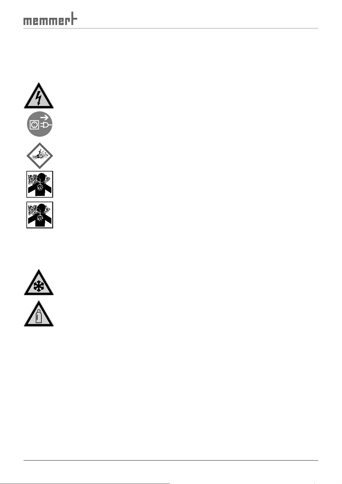
1.1.2 Icons used
Prohibited sign (forbidding an action)
Do not tilt
appliance
Warning icons (warning of a danger)
Danger of
electrical shock
Warning of gas
bottles
Regulation signs (stipulate an action)
Disconnect the
mains plug
Do not lift appliance
Explosive
atmosphere
heat/hot surfaces Gas
Wear gloves
Danger of frostbite/cold burns
Wear safety
shoes
Other icons
6
Observe
information in
separate manual
Information on
first aid
Two or more
persons required
First Aid:
Rinse eyes out
Important or
useful additional information
Page 7
Safety regulations
1.2 Product safety and dangers
Incubators of the INCO type are technically well-developed, manufactured using high-quality
materials and tested for many hours in the factory. They contain the latest technology and
comply with recognised technical safety regulations. But there are still dangers involved, even
when the appliance is used as intended. These dangers are described below.
Warning!
After removing covers, live parts may be exposed. You may receive
an electric shock if you touch these parts. Disconnect the mains plug
before removing any covers. Any work inside the unit may only be
performed by qualified electricians.
Warning!
When loading the chamber with an unsuitable load, poisonous or
explosive vapours or gases may be produced. This could cause the
chamber to explode, and people could be badly injured or poisoned.
The chamber may only be loaded with materials/test objects which
do not form any poisonous or explosive vapours when heated up
(see also Chapter 2.7 Intended use on page 14 ).
Warning!
Danger of suffocation. In high concentrations, CO
and N2 can have
2
a suffocating effect. In normal operation, the incubator gives off
small amounts of CO
and – if equipped with the O2 module – N2
2
to its environment. You should therefore ensure that the room in
which it is installed is properly ventilated. If a gas bottle is not connected, or is empty, always close the stop valve or pressure reducer
on the bottle.
Warning!
High concentrations of CO
contact with CO
gas to the eyes and skin.
2
can cause cold burns or frostbite. Avoid
2
Warning!
CO
gas bottles may burst or explode at high temperature. Do not
2
use naked flames in the vicinity of the gas bottles. Store gas bottles
at lower than 50 °C in a well-ventilated location. Prevent water from
penetrating, as well as backflow into the gas bottles. It is essential
that you read the safety notes and regulations of the gas suppliers.
CO
and N
2
are not dangerous substances in terms of the German Ordinance on Hazardous
2
Substances (GefStoffV). You should nevertheless familiarise yourself with the applicable safety
regulations prior to handling such gas bottles.
7
Page 8

Safety regulations
1.3 Requirements of the operating personnel
The incubator may only be operated and maintained by persons who are of legal age, and
who have received instructions for the incubator. Personnel who are to be trained, instructed
or who are undergoing general training may only be active on the incubator under the continuous supervision of an experienced person.
The incubator may only be transported by persons (fork-lift truck, manual pallet jack), who are
trained for this work and who know the corresponding safety regulations.
Repairs may only be performed by qualified electricians. In this case the regulations in the
separate service manual must be observed.
1.4 Responsibility of the owner
The owner of the incubator
► is responsible for the flawless condition of the incubator and for the incubator being oper-
ated in accordance with its intended use (see page 14 );
► is responsible for ensuring that persons who are to operate or service the incubator are
qualified to do this, have received instructions about the incubator and are familiar with
this operating manual;
► must know about the applicable regulations, requirements and work protection regula-
tions, and train staff acordingly;
► is responsible for ensuring that unauthorised persons have no access to the incubator;
► is responsible for ensuring that the maintenance plan is adhered to and that maintenance
and repair work is properly carried out (see page 63 );
► ensures, for example through corresponding instructions and inspections, that the incuba-
tor and its surroundings are kept clean and tidy;
► is responsible for ensuring that personal protective clothing is worn by operating person-
nel, e.g. work clothes, safety shoes, protective gloves.
1.5 Changes and conversions
No independent conversions or alterations may be made to the incubator. No parts may be
added or inserted which have not been approved by the manufacturer.
Independent conversions or alterations result in the EC declaration of conformity (see page
16 ) losing its validity, and the incubator may no longer be operated.
The manufaturer is not liable for any damage, danger or injuries that result from independent
conversions or alterations, or from non-observation of the regulations in this manual.
1.6 Behaviour in case of malfunctions and irregularities
The incubator may only be used when in a flawless condition. If you as the operator notice
irregularities, malfunctions or damage, immediately put the incubator out of service (see
Chapter 1.8 ) and inform your superiors.
You can find information on eliminating malfunctions from page 40 .
8
Page 9
Safety regulations
1.7 What to do in case of accidents
1. Keep calm. Act resolutely and with consideration. Pay attention to your own
safety.
2. Switch off the incubator and close the valves on the gas bottle.
3. Call a doctor.
4. Initiate first aid measures. If available: Call a trained first aid helper.
In case of contact with CO2 to the eyes and skin:
Rinse eyes out with water for at least 15 minutes. With cold burns, rinse with water
for at least 15 minutes. Cover over in a sterile manner. Call a doctor.
Inhaling CO2 or N2:
High concentrations can cause suffocation. Symptoms may include a loss of mobility and
consciousness. The victim is not aware of suffocating.
Low concentrations of CO
Anyone affected should breathe fresh air, using a breathing device independent of recircu-
lating air. Keep the person warm and calm. Call a doctor. In case of respiratory arrest, use
artificial respiration.
can cause accelerated breathing and headaches.
2
If gas is escaping:
Leave the room immediately, warn others and ventilate the room. If you re-enter the room,
use an autonomous breathing device (independent of ambient air) if it has not been established that the atmosphere is harmless.
1.8 Switching off incubator in an emergency
► Push main switch on front side of appliance
( Fig. 1 ).
► Close the valves on the gas bottle.
Fig. 1 Switch off incubator by
pressing the main switch
9
Page 10
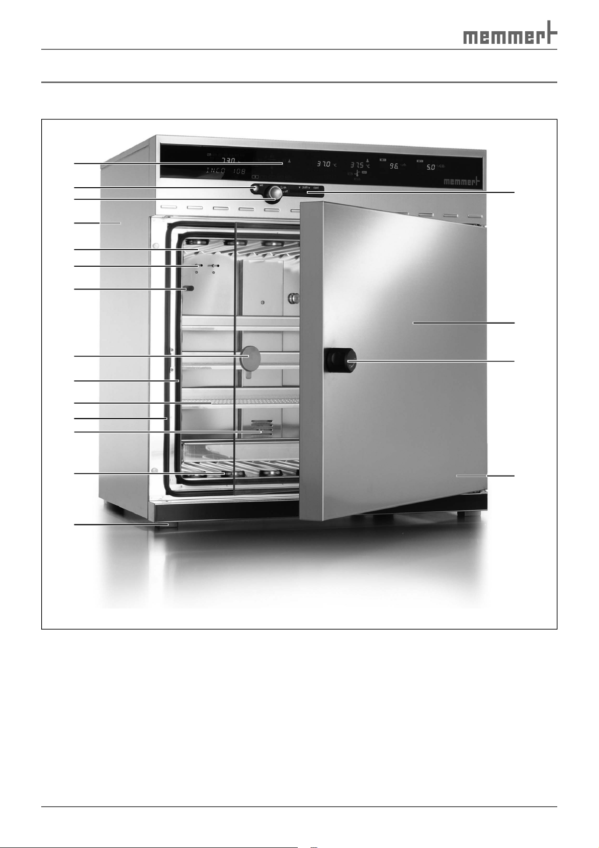
Design and Function
2. Design and Function
2.1 Design
1
10
11
12
13
2
3
18
4
5
6
7
17
8
16
9
15
14
Fig. 2 Design of INCO incubators
1 Controller/control panel (see page 29 )
2 Set key
3 Push/turn control
4 Connections on the rear of the oven
(see page 13 )
5 Heating ribs (see page 11 )
6 Pt100 temperature sensors
7 Humidity sensor
8 Glass door
9 Chamber seal
10 Sliding shelf
11 Door seal
12 Ventilator/inlet opening
13 Heating ribs
14 Adjustable feet
15 Nameplate (beneath door, see page 18 )
16 Door knob (see page 27 )
17 Door
18 Chip card reader
10
Page 11
Design and Function
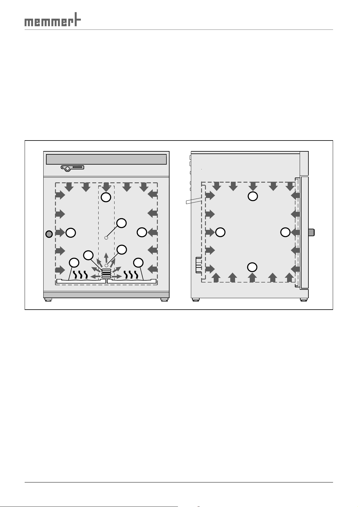
2.2 Function
The air in the incubator is heated up by an all-round heater with a large surface ( Fig. 3 , No. 1).
The CO
has a much higher specific weight than air, the gas is let into the working chamber above the
interior fan (2). The turbulence-free interior ventilation (3) ensures a uniform distribution of
the gases, creating a homogenous atmosphere.
In the basic version, humidification takes place by means of water trays (4). To avoid uncontrolled condensation, dosed fresh air is piped into the interior. If the appliance is equipped
with a humidity module, humidification takes place via a hot-air generator, which allows
water to evaporate at a set rate. The sterile hot air is let into the interior above the fan and is
mixed with the air current (5).
and/or N2 gas is introduced into the working chamber via a sterile filter. Because CO2
2
1
5
1
2
3
4
1
4
1
11
1
Fig. 3 How INCO incubators work
2.3 Optional extras
2.3.1 Basic equipment
► Electronic fuzzy-supported PID process controller with pulse width modulation and per-
manent performance adjustments and time-saving self-diagnosis system to quickly locate
errors (see page 41 )
► All-round heater with larger surface area, with additional thermal conduction layer (see
Fig. 3 )
► Capacitive humidity sensor
► Humidity control (fresh air via sterile filter) ensures that setpoint humidity is quickly
reached and guarantees short recovery times, while avoiding condensation formation
► Homogenous atmosphere and temperature distribution through encapsulated, turbu-
lence-free ventilation system
► STERICard for fully automatic sterilisation process control for hot air sterilisation of appli-
ance, including sensors and fan rotor (see page 51 )
11
Page 12

Design and Function
► Digitalised electronic CO
with self-diagnosis system and acoustic error display, air pressure compensation
control with automatic zero position, NDIR measuring system
2
► Language settings (see page 46 )
► Alphanumeric text display
► Integrated week time switch with grup function (e.g. each working day) (see page 33 )
► Retracting push-turn control for simple operation of appliance (see page 28 )
► Two separate Pt100 temperature sensors DIN Class A in a 4-wire circuit for control and
monitoring
► Digital monitoring control for overtemperature, undertemperature and automatic
setpoint following (ASF) (see page 50 )
► Mechanical temperature limiter (TB protection class 1, see page 47 )
► Monitoring relay to switch off heater in case of error
► Optical alarm display
► Acoustic signal messages if temperature or CO
if gas bottle is empty (see page 40 )
► Calibration of temperature, humidity, CO
rate PC (see from page 53 )
and O2 possible on the device without a sepa-
2
limits are crossed, when door is open and
2
2.3.2 Optionally available additional modules
Comfort module:
► Two gas connections with quick release connectors (see page 13 )
► Automatic switch-over of gas bottles
Hygiene module
► Electro-polished, seamless laser-welded chamber
Communication module
► Logging option of temperature, CO2 and relative humidity via computer/laptop
► Internal log memory with 1024 kB as ring memory for all setpoint and actual values, errors
and settings in real time and with date, logging approx. 3 months at 1 minute storage
interval (see page 62 )
► Parallel printer port (PCL3-compatible) for printing out log data (see page 13 and page 45 )
► optionally USB, Ethernet, RS-232 or RS-485 interface (see from page 58 )
CO2 module
► Extended adjustment range from 0 to 20 %
► 3-point calibration (5 %, 10 %, 15 % CO
O2 module
)
2
► Control of oxygen concentration through the introduction of nitrogen (N
range 1 % to 20 % O
(not in combination with Comfort or Premium module)
2
2
Premium module
► Includes comfort, hygiene, communication and CO
modules
2
Humidity module
► Active microprocessor humidification and dehumidification control (40-97 % rh)
12
); adjustment
Page 13
Design and Function
2.4 Material
For the outer housing, MEMMERT uses stainless steel (W.St.No. 1.4016), and for the interior,
stainless steel (W.St.No. 1.4301), which stands out through its high stability, optimal hygienic
properties and corrosion-resistance towards many (but not all!) chemical compounds (caution
for example with chlorine compounds). The chamber load for the appliance must be carefully
checked with respect to chemical compatibility with the materials mentioned.
A material resistance table can be requested from the manufacturer.
2.5 Electrical equipment
► Operating voltage: See nameplate (page 18 ), 50/60 Hz
► Current consumption: See nameplate (page 18 )
► Protection class 1, i.e. operating insulation with safety earth terminal in accordance with
EN 61010
► Protection type IP 20 acc. to EN 60 529
► Interference-suppressed acc. to EN 55011 class B
► Appliance fuse: Fusible link 250 V/15 A quick-blow
► The temperature controller is protected with a miniature fuse 100 mA (200 mA at 115 V)
► For models with a humidity model the CO
fuse
controller is protected with a 6.3 A miniature
2
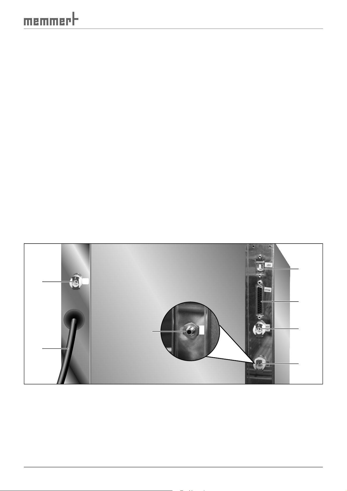
2.6 Connections
1
2
H2O
N2
7
In
3
4
5
6
Fig. 4 Connections on rear of appliance
1 Water connection (only for model with humidity module)
2 Mains lead
3 USB connection (only for models with communication or premium modules;
alternatively Ethernet, RS-232 or RS-485 connection) (details from page 58 )
4 Printer connection (only for models with communication or premium modules) (see page
45 )
5 CO
6 CO
connection to main gas bottle
2
connection to reserve gas bottle (only for models with CO2 or premium modules)
2
7 N2 connection (quick-release connector, only if equipped with O2 module)
13
Page 14

Design and Function
2.6.1 Electrical connection
Observe the country-specific regulations when making connections (e. g. in Germany DIN VDE
0100 with residual current device).
This appliance is intended for operation on an electrical power system with a system impedance Z
at the point of transfer (service line) of a maximum of 0.292 ohm. The operator must
max
ensure that the incubator is operated only on an electrical power system that meets these
requirements. If necessary, you can ask your local energy supply company what the system
impedance is.
2.6.2 Connection of external appliances
Only appliances may be connected externally (depending on the model, USB, RS 232, RS 485,
Ethernet, printer) whose interfaces comply with the requirements for safety extra-low voltage
(e.g. PC).
2.6.3 Gas connection
The oven can be connected with the supplied compressed air hose via a pressure regulator
with gas bottle monitor (DIN 8546) to a CO
gas supply.
compressed gas bottle or directly to a central CO2
2
For models with the CO
can be connected. If equipped with the O
of a second CO
gas bottle ( Fig. 4 ).
2
or premium modules, two gas bottles with quick release connectors
2
module, an N2 gas bottle can be connected instead
2
The pre-pressure must not exceed 1.2 bar. A value between 0.8 and 1 bar is considered to be
an ideal value.
2.6.4 Water connection
For models with a humidity module, the incubator can be connected with the supplied hose
to the also supplied water supply tank.
2.7 Intended use
INCO incubators may only be used for incubating cell cultures or similar. Any other use is
improper, and may result in hazards and damage.
The incubators are not explosion-proof (they do not comply with workplace health & safety
regulation VBG 24). The chambers may only be loaded with materials and substances which
cannot produce any toxic or explosive vapours at temperature ranges up to 50 ºC, and which
themselves cannot explode, burst or ignite.
The incubators may not be used for drying, vaporising and branding paints or similar materials, the solvents of which could form an explosive mixture when combined with air. If there is
any doubt as to the composition of materials, they must not be loaded into the incubator. Potentially explosive gas-air mixtures must not be produced, either in the interior of the chamber
or in the direct vicinity of the appliance.
The incubator may not be used for sterilisation purposes. It is not a steriliser with respect to
the Law on Medical Devices.
Only gas bottles with a pressure regulator may be connected to the gas connections of the
oven. Introducing other gases or materials than CO
14
or N2 is not permitted.
2
Page 15

Design and Function
2.7.1 Intended use of the INCOmed
For INCOmed incubators, which are subject to the 93/42/EEC guideline (Council Directive on
the approximation of the laws of the Member States relating to medical devices), the intended
use is defined as follows:
The CO2 incubator INCO med is intended for the creation and maintenance of constant environmental conditions for application in the field of in vitro fertilisation (IVF), especially for the
incubation of oocytes, spermatozoa and zygotes in special culture dishes for IVF application as
well as for gene expression and the biosynthesis of RNA and proteins.
15
Page 16

Design and Function
2.8 EC Declaration of Conformity
EC Declaration of Conformity
Manufacturer´s name and address: MEMMERT GmbH + Co. KG
Äußere Rittersbacher Straße 38
D-91126 Schwabach
Product: CO2 Incubator
Type: INCO 2
Sizes: 108 l / 153 l / 246 l
Nominal voltage: AC 230 V 50/60 Hz
The designated product is in conformity with the European EMC-Directive
2004/108/EEC
including amendments
Council Directive of 03 May 1989 on the approximation of the laws of the Member States relating to
electromagnetic compatibility.
Full compliance with the standards listed below proves the conformity of the designated product with the essential
protection requirements of the above-mentioned EC Directive:
DIN EN 61326-1:2006-10 EN 61326-1:2006
DIN EN 61000-3-11:2001-04 EN 61000-3-11 :2000
The designated product is in conformity with the European Low Voltage Directive
2006/95/EEC
Council Directive on the approximation of the laws of the Member States relating to Electrical
equipment for use within certain voltage limits.
Full compliance with the standards listed below proves the conformity of the designated product with the essential
protection requirements of the above-mentioned EC Directive:
DIN EN 61 010-1 (VDE 0411 part 1):2002-08 EN 61 010-1:2001
DIN EN 61 010-2-010 (VDE 0411 part 2-010):2004-06 EN 61 010-2-010:2003
Schwabach, 22.06.10
______________________________
(Legally binding signature of the issuer)
This declaration certifies compliance with the above mentioned directives but does not include a property assurance. The
safety note given in the product documentation which are part of the supply, must be observed.
including amendments
16
Modelljahr 2006 D10318 / 22.06.10
Page 17
Design and Function
Manufacturer's name and address:
MEMMERT GmbH + Co. KG
Äußere Rittersbacher Straße 38
91126 Schwabach, Germany
Product:
Incubators
Type:
INCO med
Sizes:
108 l / 153 l / 246 l
Rated voltage:
AC 230 V 50/60 Hz
EC Declaration of Conformity
This product complies with the provisions of the directive:
93/42/EEC
including annex and revisions
Council Directive on the approximation of the laws of the Member States relating to medical
devices of 14 June 1993 (Official Journal of the EC No. L 169, page 1 of 12 July 1993)
Schwabach, Germany, 01/11/2012
legally binding signature of the manufacturer)
(
This declaration states the compliance with the above Directives, however, does not provide any warranted properties.
The safety instructions in the supplied documents have to be observed.
D24002
17
Page 18
Design and Function
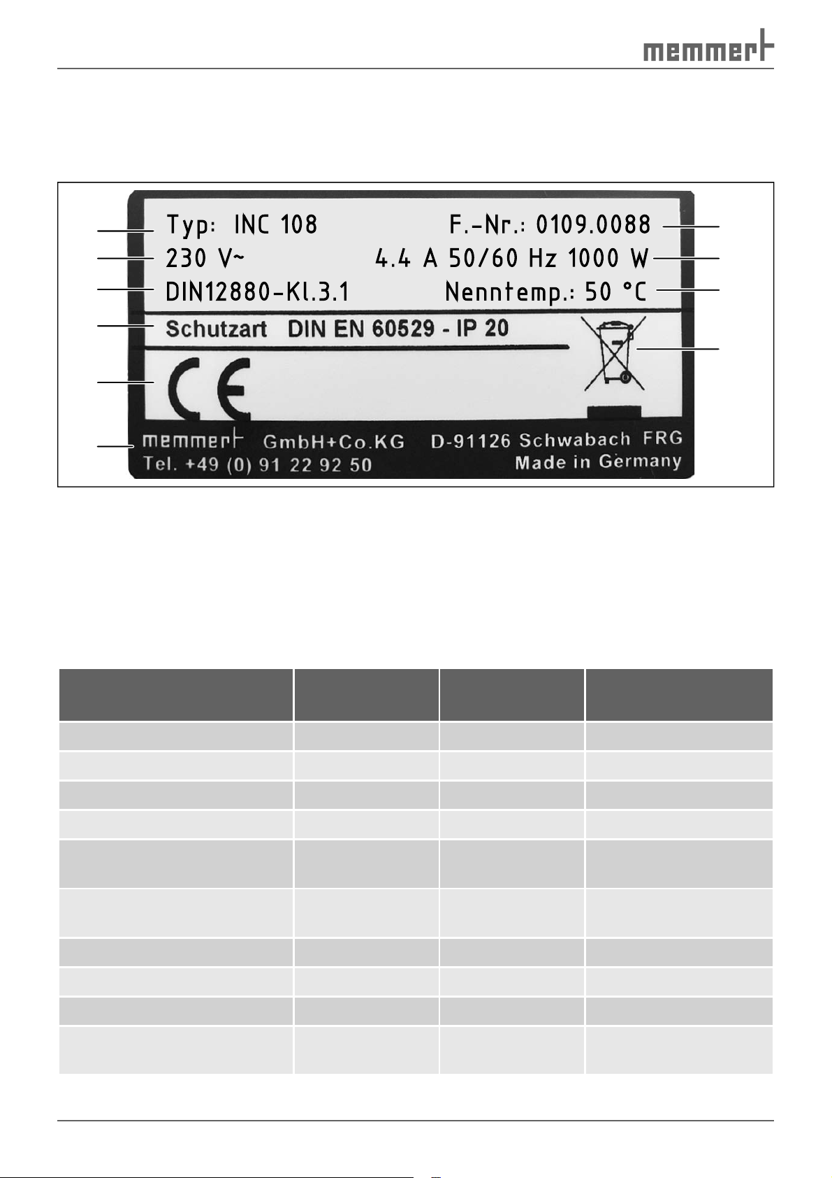
2.9 Designation (nameplate)
The nameplate ( Fig. 5 ) provides information about the appliance model, manufacturer and
technical data. It is attached to the front of the appliance, on the right beneath the door (see
page 10 ).
1
2
3
4
5
6
Fig. 5 Nameplate
1 Type designation
2 Operating voltage
3 Applied standard
4 Protection type
5 CE conformity
Typ: INC 108 F.-Nr.: 0109.0088
230 V
DIN12880-Kl.3.1 Nenntemp.: 50 °C
~
4.4 A 50/60 Hz 1000 W
6 Address of manufacturer
7 Disposal note
8 Temperature range
9 Connection / performance values
10 Factory number
10
9
8
7
2.10 Technical data
Model
* See Fig. 6 on page 20 .
Chamber width A* [mm] 560 480 640
Chamber height B* [mm] 480 640 640
Chamber depth C* [mm] 400 500 600
Appliance width D* [mm] 710 630 790
Appliance height E* (varies
due to adjustable feet) [mm]
Appliance depth F* (includ-
ing door handle) [mm]
Chamber volume [litres] 108 153 246
Weight [kg] 70 90 110
Performance [W] 1000 1500 2000
Max. number of sliding
shelves half size / full size
108 153 246
778 920 938
590 690 790
-/4 -/6 2 x 6/6
18
Page 19

Design and Function
Model
* See Fig. 6 on page 20 .
Max. load per sliding shelf
[kg]
Max. load per appliance [kg] 40 40 60
Temperature Temperature recording by means of Pt100 in a 4-wire circuit
Adjustment range: Normal mode: 20 °C to 50 °C
Sterilisation mode: 160 °C (4 hours) via STERICard
Adjustment precision: 0.1 °C
Control range: from 8 °C above room temperature to 50 °C
Variation (time): max. ±0,1 °C at 37 °C
Variation (spatial): max. ±0.3 °C at 37 °C
Humidity The relative humidity in the chamber is measured by a capac-
itive humidity sensor and displayed digitally in percent.
The measurement precision of the humidity sensor is 1 % rh
108 153 246
15 15 15
► Adjustment range: 88 to 97 % rh (for models with
humidity module 40 to 97 % rh)
► Adjustment precision: 1 % rh
CO
2
(only if equipped with O2
O
2
module)
► Display range: 10 to 98 % rh
► Variation (time): max. ±1 % rh
The CO2 content is determined through an NDIR measuring system, controlled constantly by a microprocessor and
displayed digitally in percent
► Adjustment range: 0 to 10 % (for models with CO
premium modules 0 to 20 %)
or
2
► Adjustment precision: 0.1 %
► Variation (time): max. ±0.1 % rh
► Variation (spatial): max. ±0.3 %
The O2 content is determined with a long-lasting, maintenance-free zirconium dioxide sensor, constantly controlled by
a microprocessor and displayed digitally in percent
► Adjustment range: 1 to 20 %
► Adjustment precision: 0.1 %
► Variation (time): max. ±0.1 %
► Variation (spatial): max. ±0.3 %
19
Page 20
Design and Function
D
A75 75
12
Fig. 6 Dimensions of INCO incubators
2.11 Ambient conditions
F
C
38
E
8
38
202
B
76
► The incubator may only be used in enclosed rooms and under the following environmental
conditions:
Ambient temperature: 5 ºC to 35 ºC
Humidity: max. 80 % not condensing
Degree of pollution: 2
Altitude of installation max. 3,000 m above sea level
► The incubator may not be used in areas where there is a risk of explosions. The ambient air
must not contain any explosive dusts, gases, vapours or gas-air mixtures. The incubator is
not explosion-proof.
► Heavy dust production or aggressive vapours in the vicinity of the appliance could lead to
sedimentation in the chamber interior and as a consequence, could result in short circuits
or damage to electrical parts. For this reason, sufficient measures should be taken to
prevent large clouds of dust or aggressive vapours from developing.
2.12 Accessories included
For incubators with basic fittings:
► Two (INCO 108) or three (INCO 153 and 246) sliding shelves
► Gas pressure hose
► Water tray (one for INCO 108 and 153 incubators, two for INCO 246 incubators)
► Sterilisation chipcard
Additionally, for models with humidity module:
► Water supply tank and connection hose
Additionally, for models with CO2 or premium module:
► Second gas pressure hose with quick-release connector
Additionally, for models with O2 module:
► Second gas pressure hose with quick-release connector
20
Page 21

Delivery, Transport and Setting Up
3. Delivery, Transport and Setting Up
3.1 Safety regulations
Warning!
You may injure your hands or feet when transporting and
installing the incubator. You should wear protective gloves
and work shoes.
Warning!
Because of the weight of the incubator, you could injure yourself if
you try to lift it on your own.
If possible, only transport the incubator with a fork-lift truck or
manual pallet jack. The incubator may only be moved using a means
of transport by persons who have the required qualification for this
(e.g. fork-lift truck licence). This incubator may not be transported
with a crane.
If the incubator has to be carried, at least two people are required
for models 108 and 153, and at least four people for model 246.
Warning!
The incubator could fall over and seriously injure you. Never tilt the
incubator and transport it only in an upright position.
3.2 Transport
The incubator can be transported in three ways:
► with a fork-lift truck; move the forks of the truck entirely under the incubator
► on the manual pallet jack.
► by carrying; to do this, at least two people are required for models 108 and 153, and four
people for model 246. Read the weight information detailed on page 18 .
3.3 Delivery
The incubator is delivered in cardboard packaging on a cardboard pallet.
3.3.1 Unpacking
1. Remove cardboard packaging or cut open carefully along an edge.
2. Lift up incubator from pallet and put down on the appliance feet.
3.3.2 Checking for completeness and transport damage
► Check the delivery note to ensure that the delivery is complete.
► Check the inside and outside of the incubator for damage.
If you notice deviations from the delivery note, damage or irregularities, do not put the incubator into operation, but inform the haulage company and the manufacturer.
3.3.3 Disposing of packaging material
Dispose of the packaging material (cardboard) in accordance with the effective legal disposal
regulations for cardboard packaging in your country.
21
Page 22

Delivery, Transport and Setting Up
3.3.4 Storage after delivery
If the incubator is initially to be stored after delivery: Read the storage conditions from page
65 .
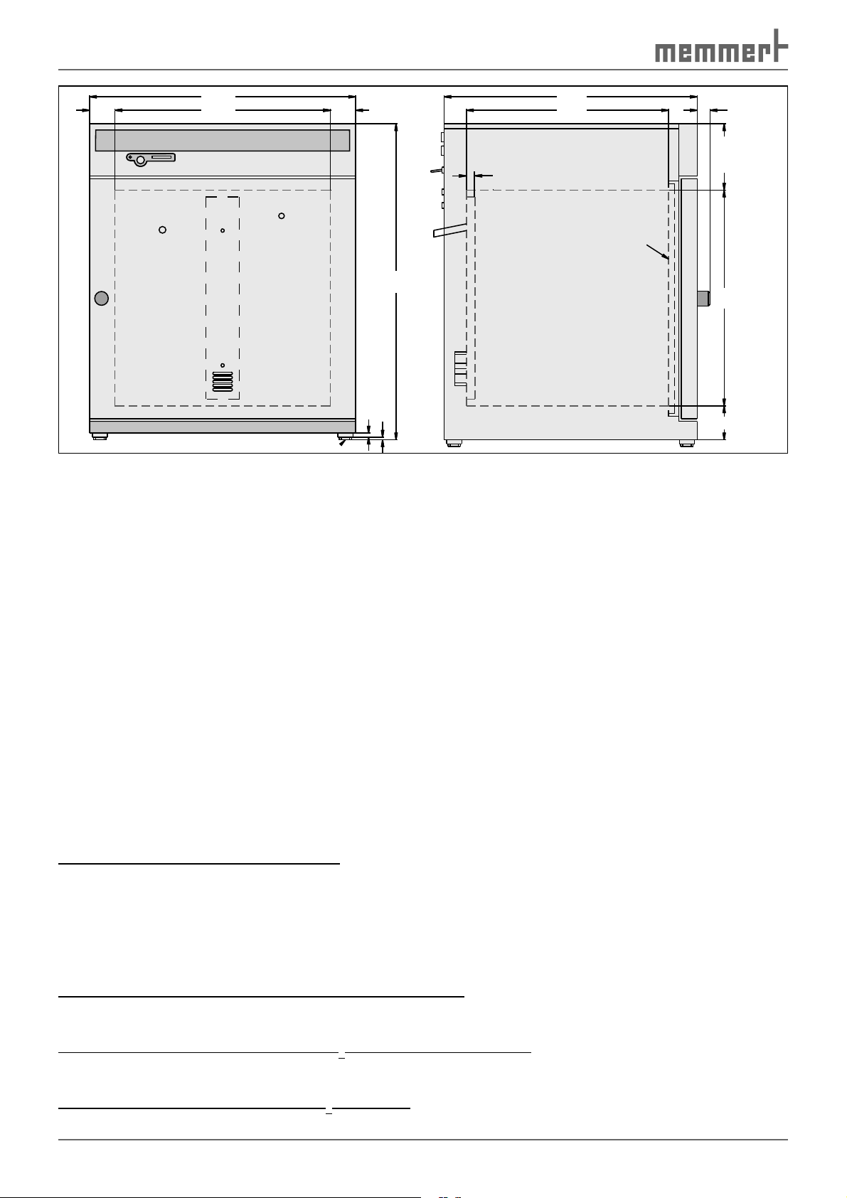
3.4 Setup
The incubator can be placed either on the ground or on a table (work surface). When doing
this, ensure that the appliance is positioned exactly horizontally. The installation site must be
level and able to reliably carry the weight of the incubator (see page 18 ). Do not place the appliance on an inflammable surface.
A power connection must be available at the installation site in accordance with the connection data on the nameplate (see page 18 ).
The distance between the wall and the rear of the chamber must be at least 15 cm. The clearance from the ceiling must not be less than 20 cm and the side clearance from the wall not
less than 8 cm ( Fig. 7 ). Sufficient air circulation in the vicinity of the chamber must be guaranteed at all times.
FP
FP
FP
Fig. 7 Minimum clearance from walls and ceiling
FP
22
Page 23

Delivery, Transport and Setting Up
3.4.1 Base (accessory)
The incubator can be placed on a base ( Fig. 8 ).
3.4.2 Stacking frame (accessory)
Two appliances of the same model size can be placed on top of one another. To do this, foot
alignment provisions must be attached to the lower oven ( Fig. 9 ):
1. Remove the housing cover from the lower oven.
2. Insert drilling template (supplied with the foot alignments) into the overturned lid.
3. Mark drilling points and drill with a 4.2 mm diameter drill bit.
4. Screw the foot alignment provisions to the top of the lid with the screws and nuts supplied.
5. Put the covers back on.
Fig. 8 Base
Fig. 9 Assembly of the foot alignment
provisions when two incubators are
placed on top of one another
23
Page 24

Putting into Operation
4. Putting into Operation
4.1 Checks
4.1.1 Checking the temperature sensor
Especially strong vibrations during transport could
result in the temperature sensors being moved
in their holders in the working chamber.
Check the temperature sensor for its correct
positioning and if necessary adjust its position
in the holder ( Fig. 10 ).
4.1.2 Check the door and adjust if
necessary
See page 64 .
4.2 Connecting
4.2.1 Power supply
Caution:
Observe the country-specific regulations when making connections (e. g. in Germany DIN VDE 0100 with residual current
device / RCD). Observe the connection and power ratings (see nameplate).
The incubator is intended for operation on an electrical power system with a system impedance Z
must ensure that the incubator is operated only on an electrical power system that meets
these requirements. If necessary, you can ask your local energy supply company what the
system impedance is.
Connect power cable (see Fig. 4 on page 13 ).
at the point of transfer (service line) of a maximum of 0.292 ohms. The operator
max
Fig. 10 Temperature sensor
4.2.2 External devices
(only for models with communication or premium modules)
Only appliances whose interfaces comply with the requirements for safety extra-low voltge
(e.g. PC, laptop, printer) may be connected to the connections on the rear of the incubator
(see Fig. 4 on page 13 ). Which devices may be connected depends on the chosen model /
module variant ( Communication interfaces described in detail from page 58 ).
4.2.3 Water connection
(only for models with humidity module)
Only use distilled water or DI water.
1. Fill up the supplied water supply tank (canister) with distilled water and place behind/
next to the incubator.
2. Attach the supplied hose the quick-release connections to the canister and the water supply "H
24
O“ on the rear of the appliance (see Fig. 4 on page 13 ).
2
Page 25

4.2.4 Gas connection
Warning!
Danger of suffocation: In high concentrations, CO
a suffocating effect. In normal operation, the incubator gives off
small amounts of CO
to its environment. You should therefore ensure that the room in
which it is installed is properly ventilated.
Warning!
High concentrations of CO
contact with CO
gas to the eyes and skin.
2
Warning!
CO
gas bottles may burst or explode at high temperature. Do not
2
use naked flames in the vicinity of the gas bottles. Store gas bottles
at lower than 50 °C in a well-ventilated location. Prevent water from
penetrating, as well as backflow into the gas bottles. It is essential
that you read the safety notes and regulations of the gas suppliers.
For incubators with basic fittings:
Putting into Operation
and N2 can have
2
and – if equipped with the O2 module – N2
2
can cause cold burns or frostbite. Avoid
2
Attach the supplied pressure hose to the
gas bottle (pressure regulator) and to the
"CO
" connection on the rear of the appli-
2
ance with two hose clamps ( Fig. 11 , see
also page 13 ).
Fig. 11
Gas connection for incubators with basic
fittings
For incubators with CO2 or premium module:
Two gas bottles can be connected by simply
pushing the supplied pressure hoses onto
the "CO
connections on the rear of the appliance
( Fig. 12 , see also page 13 ).
Connect the main gas bottle to "In1", a reserve gas bottle can be connected to "In2".
Attach the pressure hose to the gas bottles
(pressure regulator) with hose clamps.
In1" and "CO2 In2" quick-release
2
„CO2 In“
„CO2 In1“
In2“
„CO
2
CO
CO
2
CO
2
2
Fig. 12
Gas connection for incubators with CO
or Premium modules
2
25
Page 26

Putting into Operation
For incubators with O2 module:
► Attach the supplied CO
to the CO
gas bottle (pressure reducer)
2
pressure hose
2
and to the “CO2 In” connection on the
rear of the incubator with a hose clamp
( Fig. 13 , see also page 13 ).
► Attach (push on) the supplied N
sure hose to the N
reducer) and to the “N2 In” connection
on the rear of the incubator with a hose
clamp.
gas bottle (pressure
2
4.3 Oxygen calibration
(only for models with O2 module)
Perform an O
into operation (see page 57 ).
calibration before putting
2
pres-
2
„CO2 In“
„N
In“
2
CO
2
Fig. 13
Gas connection for incubators with O
ule
N
2
mod-
2
26
Page 27

Operation and control
5. Operation and control
5.1 Operating personnel
The incubator may only be operated by persons who are of legal age and have received instructions for the incubator. Personnel who are to be trained, instructed or who are undergoing general training may only be active on the incubator under the continuous supervision of
an experienced person.
5.2 Opening the door
► To open the door, turn handle to the right ( Fig. 14 ).
► To close, turn door handle to the left.
When the door is opened, the CO
cally interrupted. If the heated outer door is left open for
any length of time, condensation may form on the glass
door.
5.3 Loading the incubator
Warning!
When loading the chamber with an
unsuitable load, poisonous or explosive
vapours or gases may be produced. This
could cause the chamber to explode, and people could be badly injured or poisoned. The chamber may only be loaded with materials/
test objects which do not form any toxic or explosive vapours when
heated up, and which cannot ignite. If there is any doubt as to the
composition of materials, they must not be loaded into the incubator.
Caution:
Check the chamber load for chemical compatibility with the materials of the incubator
(see page 13 ), since considerable damage could otherwise occur to the chamber load,
the appliance or the surroundings.
supply is automati-
2
close
Fig. 14 Opening and
closing the door
open
The incubators are not explosion-proof (they do not comply with workplace health & safety
regulation VBG 24) and are therefore not suitable for drying, vaporising and branding paints
or similar materials, the solvents of which could form an explosive mixture when combined
with air. Potentially explosive gas-air mixtures must not be produced, either in the interior of
the chamber or in the direct vicinity of the appliance.
Heavy dust production or aggressive vapours in the chamber or in the vicinity of the appliance could lead to sedimentation in the chamber interior and as a consequence, could result
in short circuits or damage to electrical parts. For this reason, sufficient measures should be
taken to prevent large clouds of dust or aggressive vapours from developing.
The chamber must not be loaded too tightly, so that proper air circulation in the working
chamber is guaranteed. Do not place any of the chamber load on the floor, touching the side
walls or right below the ceiling (heating ribs) of the working chamber. To guarantee an optimal air circulation, push in the sliding shelves so that the gaps between the door, sliding shelf
and rear wall of the chamber are roughly the same size.
27
Page 28
Operation and control
5.4 Inserting water tray(s)
(for appliances with basic fittings)
Fill the water tray with distilled water and push into the lowest slot ( Fig. 15 ).
INCO
model
108 1 1.5 to 2.5 1 to 1.5
153
246 2
Fig. 15 Inserting water tray(s)
Number
of
water
trays
1 1.5 to 2.5 1 to 1.5
Filling
level in
cm for
each tray
approx.
1.5 to 2.5 1 to 1.5
each tray
Amount
of water
in ltr. for
approx.
5.5 Connect gas supply
1. Check that the gas bottle(s) is properly connected (see also page 13 ).
2. Open valve(s).
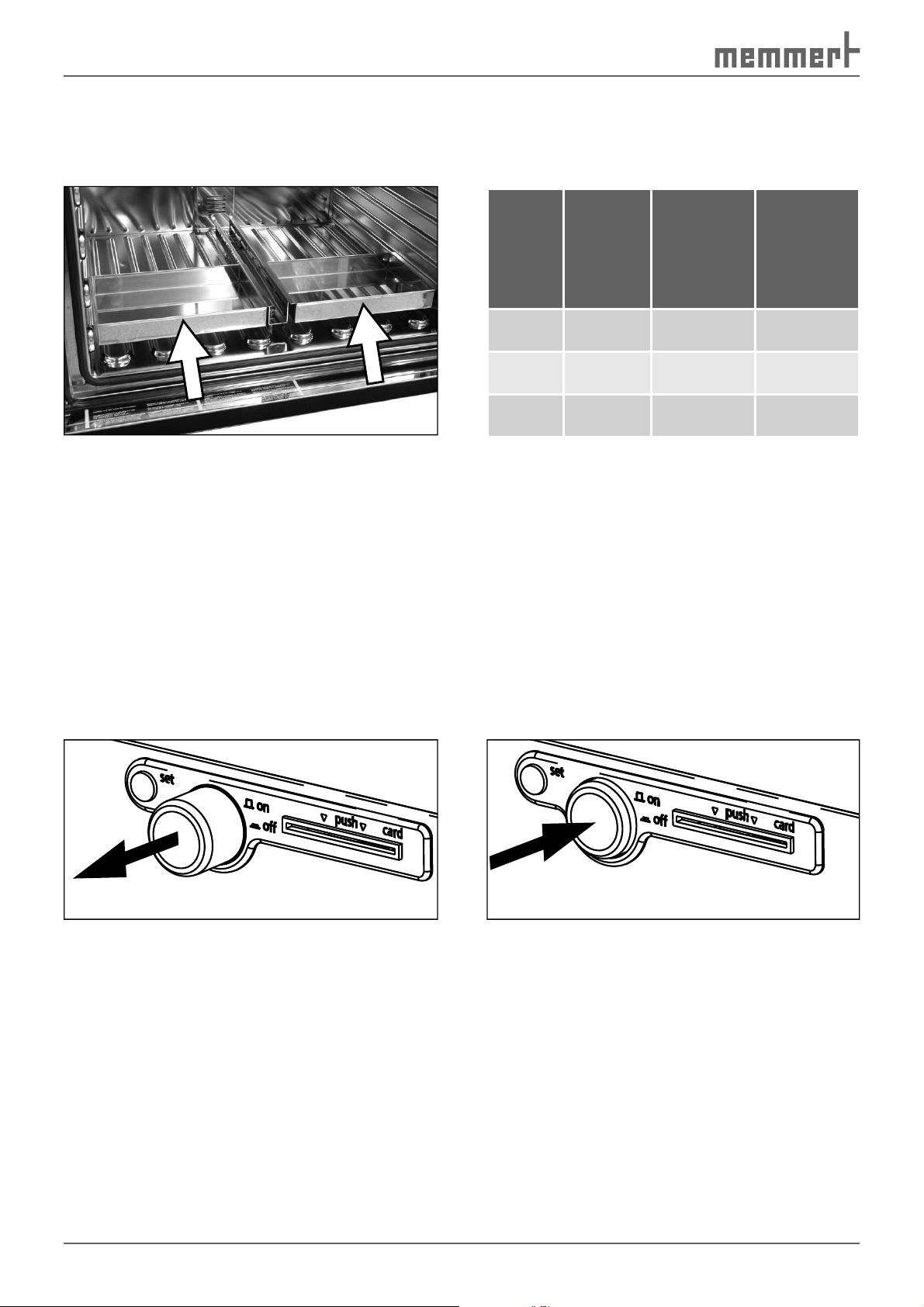
5.6 Switch on appliance
The incubator is switched on and off by pressing the main switch/ push-turn control on the
front of the appliance.
► Switching on: press the main switch so that it comes out of the appliance ( Fig. 16 ).
► Switching off: press the main switch so that it retracts back into the appliance ( Fig. 17 ).
Fig. 16 Switching on incubator
Fig. 17 Switching off incubator
28
Page 29

Operation and control
5.7 Basic operation
The desired parameters are entered on the operating panel of the controller on the front of
the appliance ( Fig. 18 ). Basic settings, as well as those for time and printing, can also be made
here. In addition, programmed and current parameters are displayed, as well as warning messages:
123465 7 8 109 11 12
Tu
Mo
We
on
off
Sa Su
Fr
Th
t1
t3
t2
PRINT
4
t4
3
loop
2
1
SETUP
Fig. 18 Operating panel
1 Time display
2 Display appliance locked with user-ID
card (see page 52 )
3 Display appliance is heating up
4 Sterilisation mode (see page 51 )
5 Temperature display
6 Alarm display
7 Monitoring temperature display
(see page 47 )
8 Horn
set
All operating functions are selected by turning the push-turn control to the
left or right...
STERI DEFRO
IN 1
°C
MIN
°C
MAX
AUTO
OUT
IN 2
rh
%
mb
IN 1
OUT
IN 2
13141516
9 Warning water supply tank empty
10 Humidity display
11 Gas bottle 1 active
12 Gas bottle 2 active
13 CO
display
2
14 Display appliance is humidifying
15 Operating mode display (see page 30 )
16 Text display/O
display (O2 display only if
2
equipped with O2 module)
CO
mb
2
set
...and adjusted by turning this with the SET key held down.
5.8 Setting parameters
In general, all setting actions on the operating panel described on the following pages are
made in the same way:
set
set
set
Settings for other parameters are made in the same way.
1. You select the desired parameter with the push-turn control (menu item, e. g.
temperature); then all other parameters go dark and the selected one flashes.
2. With the SET key held down, set the desired value (e. g. 37.0 °C) with the
push-turn control.
3. Release the SET key, and the set value is saved. The display briefly shows the
set value, flashing. The current temperature is displayed and the incubator
begins to heat up to the set temperature.
29
Page 30

Operation and control
t
The control returns automatically to the main menu if the push-turn key or set key is
not operated for approx. 30 seconds.
Setting the temperature (Quick adjustment):
1. Hold down the SET key and set the desired temperature setpoint with the push-turn
control.
2. Release the SET key
The appliance flashes briefly, showing the temperature setpoint. Then the current temperature
appears on the display and the controller begins to move to the set temperature.
5.9 Operating modes
INCO incubators can be operated in three ways ( Fig. 19 ).
► Normal mode: The incubator runs in permanent operation at the temperature, humidity
and CO
31 .
► Week time switch: The incubator runs at the set values only at certain times. Operation in
this mode is described from page 33 .
values set on the operating panel. Operation in this mode is described from page
2
► Interface mode with PC/laptop (for models with communication or premium modules, see
from page 58 )
In addition, basic appliance settings can be made (SETUP, see page 45 ) and printouts can be
made if the appliance is equipped with the communication or premium module (PRINT, see
page 45 ).
SETUP
Basic appliance
settings
(see Page 45 )
Normal
operation
(see Page 31 )
Fig. 19 Operating modes
Week time
switch
(see Page 33 )
PRINT
Printer
(see Page 45 )
5.10 Setting the operating mode
se
1. Hold SET key down for approx. three seconds, the selected operating mode
then begins to flash.
set
set
30
2. Select the desired operating mode (normal mode, week time switch, programming mode, printer or basic appliance settings/setup by turning control
with SET key held down.
3. Release the SET key, and the selected operating mode is saved.
Page 31

Operation and control
5.10.1 Normal mode
The appliance runs in this operating mode in permanent operation. The desired setpoints for
operating the chamber can be selected. The settings have an immediate effect on the functions of the appliance.
1. Load incubator (see page 27 ).
2. Switch on appliance. To do this, press the push-turn control on the operating panel so that
it comes out of the appliance (see Fig. 16 on page 28 ).
3. Select the normal operating mode
with the push-turn control:
PRINT
SETUP
4. As described above, set the individual parameters with the push-turn control and the set
key:
Temperature setpoint
Adjustment range: 20°C to 50°C
°C
Temperature monitoring
Adjustment range:
MIN MAX AUTO
°C
(see also page 47 )
MIN
AUTO
MAX
Humidity setpoint
rh
Adjustment range:
%
► For incubators with basic
fittings: 88 to 97 %rh
► For models with humidity
module: 40 to 97 %rh
CO2 setpoint
Adjustment range: 0 bis 10 %
(or models with CO
modules 0 to 20 0 to 20 %)
O2 setpoint
(only for models with O
ule)
Adjustment range:
Off, 1 to 20 %
or premium
2
mod-
2
2
Sa Su
Mo
on
off
Tu
We
Th
CO
Fr
o2=3.4%
t2
t1
31
Page 32

Operation and control
5.10.2 Settings example normal mode
With a 5% CO2 content, a 3% oxygen content and a humidity of 96%, the appliance should
heat up to 37°C. The monitoring function should respond at 38.5 °C ( Fig. 20 ).
50
Monitoring temperature
40
30
20
10
Temperature in °C
Time Time Time
100
80
60
40
20
Humidity rh in %
Fig. 20 Example for normal mode
1. Setting the normal operating mode:
Hold SET key down for approx. 3 seconds, the current
operating mode then begins to flash.
Select the
operating mode with the push-turn control, while the SET key is held down. After you let go of
the SET key, the control is in the normal operating mode.
2. Setting the temperature setpoint:
Hold down the SET key and set the desired temperature
setpoint of 37.0 °C with the push-turn control.
25
20
in %
2
15
CO
10
5
25
20
in %
2
O
15
10
5
PRINT
Time
SETUP
°C
Release the SET key, the appliance will briefly flash, showing the temperature setpoint. Then the current temperature
appears on the display and the controller begins to move
to the set temperature of 37.0 °C.
► Heating up is indicated by the icon.
3. Setting the monitoring temperature:
Turn the push-turn control to the right until the monitor-
ing temperature and the MIN or MAX icon flashes. Hold
down the SET key and with the push-turn control, set
the overtemperature limit to 38.5 °C and the undertemperature limit to 36.0 °C. Turn the push-turn control to
the right until the monitoring temperature and the AUTO
icons flash. Hold down the SET key and set to on with the
push-turn control.
The tolerance band is set in the SETUP menu (see
page 46 ).
°C
MAX
MIN
AUTO
32
Page 33

4. Setting the humidity setpoint:
Turn the push-turn control to the right until the humid-
ity display flashes. Hold down the SET key and set the
desired humidity setpoint of 96.0 %rh with the push-turn
control. After releasing the SET key, the humidity setpoint
briefly flashes. The current humidity value appears on
the display and the controller begins to move to the set
value.
Operation and control
rh
%
The humidification process is indicated by the
icon
(only for models with humidity module).
5. Setting the CO2 setpoint
Turn the push-turn control to the right until the CO
2
display flashes. Hold down the SET key and set the desired
CO
setpoint of 5.0 % with the push-turn control. The
2
appliance flashes briefly, showing the CO
current CO
actual value appears on the display and the
2
controller begins to move to the set CO
setpoint. The
2
setpoint.
2
Depending on the bottle used, fumigation is displayed by the
IN 1
6. Adjust the O2 setpoint
(only for models with O
2
Turn the push-turn control to the left until the O
flashes. Hold down the set-key and set the desired O
IN 2
or
module)
icon.
display
2
2
Mo
on
off
Tu
We
setpoint of 3.0 % with the push-turn control. Release
the set-key. The appliance flashes briefly, showing the O
setpoint. Then, the current O2 actual value appears on
2
o2=3.0%
the display and the controller begins to move to the set
O
value.
2
The incubator is now running in permanent operation with the set values.
Th
CO
Fr
2
Sa Su
5.10.3 Week time switch
In this operating mode, the appliance switches on and
off automatically at the times programmed.
PRINT
During the OFF phase of the week time switch, the
appliance is in standby mode. The heating and cooling functions, along with the CO
humidity supply are switched off here and the controller display shows the time, dimmed.
The sequence of the week time switch repeats itself each week.
In total, a maximum of 9 time blocks can be programmed, consisting of the switching on and
switching off times.
and
2
SETUP
33
Page 34

Operation and control
Weekday
Adjustment range: Monday to Sunday
Day groups
Adjustment range: Working days Mo-Fr
Weekend Sat-Sun
No switch on time: ---Appliance not switched on on this day
Switch on time (on)
Adjustment range: 00:00 to 23:59 hours
Switch off time (off)
One minute beyond the switch on time up to
24:00
By turning further to the right, parameters (temperature, humidity setpoints etc.) can be
selected as in the normal operating mode.
Mo
Mo
Mo
on
off
on
off
on
off
Tu
Tu
Tu
We
We
We
Th
Th
Th
Fr
Fr
Fr
Sa
Sa
Sa
h
h
Su
Su
Su
If no settings (temperature setpoint etc.) are made for the ON phase, the controller takes
over the values from the normal operating mode.
For reasons of safety, you should always check that only one switch one time is programmed
in the desired time blocks and days. By turning further to the right, parameters (temperature
setpoint etc.) can be selected as in the normal operating mode.
If the controller is in standby mode or the week time switch is in the ON phase, the temperature setpoint can be directly accessed by briefly pressing the SET key. By turning the control to
the right, you are returned to temperature monitoring, humidity and CO
to the left, you come back to the settings for the individual time blocks.
setting. By turning
2
34
Page 35

Operation and control
5.10.4 Settings example week time switch
From Mo-Fr (workdays group), the appliance should switch on at 9.30 and switch off at
19.00. In addition it should work on Saturday from 10.00 to 14.00 ( Fig. 21 ).
24:00h
12:00h
01:00h
9:30h - 19:00h
Mo
9:30h - 19:00h
Tu
9:30h - 19:00h
We
9:30h - 19:00h
Th
Fig. 21 Operation with week time switch (example)
1. Setting the week time switch operating mode
Hold the SET key down for approx. 3 seconds, the current
operating mode then begins to flash. Select the week
time switch operating mode with the push-turn control,
while the SET key is held down.
Release the SET key, the control is now in the week time
switch operating mode.
2. Switch on Mo-Fr at 09:30
Turning the push-turn control to the left, select the
"Mo-Fr on" icons (group working days).
Hold down the SET key and set the desired switch-on
time with the push-turn switch to 9:30.
9:30h - 19:00h
10:0h -
14:00h
Fr
Mo
Sa
Tu
on
off
We
Su
Th
PRINT
Fr
SETUP
Sa Su
3. Switch off Mo-Fr at 19:00
Select "Mo-Fr off" (group working days) with the push-
turn control.
Hold down the SET key and set the desired switch-off
time with the push-turn switch to 19:00.
Mo
on
off
Tu
We
Th
Fr
Sa Su
35
Page 36

Operation and control
4. Switch on Sa at 10:00
With the push-turn control, select "Sat on".
Hold down the SET key and set the desired switch-on
Tu
on
off
We
Th
Sa
Su
Fr
h
Mo
time with the push-turn switch to 10:00.
5. Switch off Sa at 14:00
With the push-turn control, select "Sat off".
Hold down the SET key and set the desired switch-off
Tu
on
off
We
Th
Sa
Su
Fr
h
Mo
time with the push-turn switch to 14:00.
5.10.5 Operation with PC/ laptop (optional)
If equipped with the communication or premium module, the incubator can optionally be
used, controlled and programmed with a PC/laptop. It has corresponding communication
interfaces for this purpose (see page 13 and page 58 ).
Operation is described in a separate manual. It is delivered with the incubator for
the relevant models.
5.11 During operation
Regularly check the water level. If necessary, add distilled water.
Warning messages during operation: See Page 40 .
CO2 mode
In the heating up phase, the CO2 controller is initially deactivated. The CO2 intake is interrupted during this period. About 5 minutes after the setpoint temperature has been reached,
the CO
valve on the gas bottle must be open). To ensure a homogenous distribution of the CO
the interior, the gas is piped in above the chamber fan. The setpoint can be adjusted in 0.1 %
steps from 0 to 10% (for models with CO
Displays in CO2 mode:
control begins measuring and CO2 gas is let in to the chamber via a sterile filter (the
2
or premium modules 0 to 20 %)
2
After a sterilisation procedure, and in cycles every 24 hours, an automatic zero balance
adjustment is carried out. This automatic zero balance adjustment is completed after a
few minutes.
HEAT UP is shown during the heating up phase of
HEAT UP
the CO
sensor. In the CO2 display, CO2 is shown.
2
gas in
2
36
AUTOZERO - DO NOT OPEN DOOR is displayed during the
zero balance adjustment.
Page 37

Operation and control
IN 1
IN 2
OUT
CO
After the setpoint temperature has been reached,
the CO
on the setting.
is active.
2
Is displayed if the CO2 concentration exceeds the
defined setpoint by at least 1 % for more than 3
minutes. If the concentration is higher, the CO
display and the
In this case you should open the door for 30 sec.
and wait to see if the controller steadily adjusts
to the setpoint. If the error occurs again, contact
Customer Service.
CO2 empt is displayed if gas bottle 1 and/or 2 is/are
empty. In this case, you should connect new gas
bottles (see page 28 ).
concentration is displayed in %, depending
2
This monitoring function only starts to work
once the CO
IN 1
indicates that gas bottle 1
icon flash.
setpoint has been reached.
2
2
The pressure in the gas bottles is a constant
approx. 57 bar at 20 °C ambient temperature. It
is not possible to determine how full the bottle
is through the pressure, since the pressure only
drops immediately before the bottle is completely empty.
The CO2 supply is automatically interrupted when
the outer doors are opened. door open is indicated
in the text display.
on
off
empty
is displayed if the N2 supply is interrupted. In this
case, check if the N
and if the valve is open.
If that does not solve the problem, you should connect a new gas bottle (see page 25 ).
bottle is correctly connected
2
2
Automatic switch-over of CO2 gas bottles (only for models with comfort or premium
modules)
The automatic switch-over of gas bottles guarantees an uninterrupted supply with CO2 gas
when two independent supply systems are connected.
► Gas bottle 1 is always the main supply bottle.
► Gas bottle 2 is always the reserve bottle.
Operation is only possible with one bottle. In this case it must be connected to IN1 (see also
Fig. 4 on page 13 ).
37
Page 38

Operation and control
To be on the safe side, a freshly filled CO2 gas bottle should always be used. So if the gas in
bottle 1 is used up, you connect the opened bottle to IN1 and the newly filled bottle as a
reserve bottle to IN2.
The hose connection system used by Memmert shuts off automatically if a connection hose is
pulled off. You should still always close the stop valve on the gas bottle if a bottle is empty or
not connected.
lights up when gas bottle 1 is active. If gas bottle 1 is empty,
IN 1
IN 2
In the following cases, a switch-over is made from reserve bottle 2 back to the main supply
bottle 1:
there is an automatic switch-over to the reserve bottle.
lights up after the switch-over to gas bottle 2 (reserve bottle).
Switching over to the reserve bottle is marked by a short repeated acoustic signal (about 3 seconds long) (the default after
switching on is gas bottle 1).
► if the reserve bottle is empty
► each time after the appliance is switched on
► after every change of the CO
Humidity limit control
A humidity limit control prevents the formation of condensation water in the chamber and
at the same time ensures that the setpoint humidity is quickly reached, with short recovery
times.
The maximum achievable humidity can be adjusted in the standard model from 88 to 97% rh.
Active humidity control (only for models with humidity module)
The active humidity control guarantees that setpoint humidity is quickly reached, without the
use of water trays.
In the heating up phase, the humidity control is initially deactivated. Approx. 5 minutes after
the setpoint temperature is reached, the humidification and dehumidification control starts
working. The setpoint can be set from 40 to 97 % rh. The humidity setpoint can also be adjusted during the transient state. For humidification, water is let into the chamber via a dosing
pump. To avoid the formation of germs, the steam is first heated to approx. 140 °C. Dehumidifcation takes place through the supply of dry air via a sterile filter.
If no humidity is required in the chamber, the humidity control can be deactivated by
setting it to OFF.
setpoint
2
38
Page 39

5.12 Ending operation
1. Switch off appliance. To do this, press the
main switch on the operating panel so
that it clicks into place in the appliance
(see Fig. 22 ).
2. Close the valve(s) of the gas bottle(s).
3. Open the door (see page 27 ).
4. Remove the chamber load.
5. For appliances with the basic model:
Remove and empty the water trays. Fill
water trays and insert them only when
the appliance is next used.
For incubators with a humidity module,
empty the water tanks if the incubator is
not used for several days.
Operation and control
Fig. 22 Switching off incubator
39
Page 40

Warning messages and malfunctions
6. Warning messages and malfunctions
6.1 Warning messages
An intermittent tone is also set off by the warning messages. This can be temporarily
switched off by pressing the SET key.
DOOR OPEN if the door of
appliance is opened for
longer than 3 minutes.
Remedy: Close the door
Error in the temperature control system (see also Chapter “ Temperature monitoring ”
on page 47 ):
Tb active - temperature
limiter triggered if the
temperature limiter
responds
hi-alarm - overtemperature alarm limit max exceeded if overtemperature
protection responds
Remedy: Switch off the appliance
and leave to cool down. If the
error occurs again after switching the
appliance back on: Switch off
the appliance and Contact the
customer service
Remedy: Check the setting of
the MAX temperature monitoring (see Chapter “ Temperature
monitoring ” on page 47 .
lo-alarm - undertemperature alarm limit min
crossed if undertemperature
protection responds
asf alarm - temperature
outside tolerance band if
automatic monitoring
function responds
Remedy: Check the setting of
the MIN temperature monitoring (see Chapter “ Temperature
monitoring ” on page 47 .
Remedy: Check the setting of the
ASF temperature monitoring (see
Chapter “ Automatic temperature
monitor (ASF) ” on page 50 .
Error in humidity system (only for appliances with humidity module)
if the water supply is
defective
Remedy: Check that the water
supply hose is properly connected. Fill the water supply tank
with distilled water if it is empty.
40
Page 41

Warning messages and malfunctions
Mo
Tu
W
Th
Fr
Sa Su
Error in CO2 system:
If humidity exceeds the
preset setpoint for longer
than 30 minutes.
if the CO2 supply is defective
If the CO2 concentration exceeds the defined
setpoint by at least 1 % for
more than 3 minutes.
Remedy: Open door for 30 sec.
and wait to see if the controller
steadily adjusts to the setpoint.
If the error occurs again, Contact
the customer service.
Remedy: Set CO2 setpoint value
to 0, check stop valve of gas
bottle(s) and ensure that they
are properly connected; if gas
bottle(s) empty, change gas bottles, set CO
setpoint to desired
2
value
Remedy: Open door for 30 sec.
and wait to see if the controller
steadily adjusts to the setpoint.
If the error occurs again, Contact
the customer service.
Error in O2 system:
e
on
off
empty
2
if the N2 supply is defective Remedy: check if the N2 bottle
is correctly connected and if the
valve is open. If that does not
solve the problem, you should
connect a new gas bottle (see
page 25 ).
6.2 System/ appliance errors
Warning!
After removing covers, live parts may be exposed. You may receive
an electric shock if you touch these parts. Malfunctions requiring intervention inside the appliance may only be rectified by electricians.
You must read the separate service manual for the INCO incubator
for this.
Do not try and rectify the error yourself, but contact an authorised customer service point for
MEMMERT appliances or Contact the customer services department directly of the company
MEMMERT (see page 2 ).
In case of enquiries, please always specify the model and appliance number on the nameplate
(see page 18 ).
41
Page 42

Warning messages and malfunctions
Error Possible causes Remedy
Nothing shows on the
display although the
incubator is switched
on.
Appliance cannot be
operated
No CO
in the CO
display shown
2
module
2
icon flashes ...
Power supply
interrupted
Appliance fuse or
miniature fuse or
controller faulty
Appliance error
Mainboard faulty
Incubator locked with
user-ID card
Push/turn control
faulty
Switched mode power
supply SP 200 faulty
Temperature fuse
(TWW, ASF) has responded
Check power supply and fuse/safety
switch.
Contact the customer service and read
the service manual.
Unlock incubator with user-ID card (see
page 52 ).
Contact the customer service and read
the service manual.
Contact the customer service and read
the service manual.
► Increase temperature difference
between monitoring and working
temperature (see page 47 ).
► Replace Pt100 temperature sensor
of monitoring controller if necessary
(see Service manual)
... and rh empty
... and rh empty
... and co2 over
... and error Autozero
Error display (E...) in
display
Water supply tank
empty
Set humidity setpoint to OFF, fill up
distilled water, then reset humidity
setpoint back to desired value.
Humidity setpoint
exceeded
Open door for 30 sec. and wait to see if
subsequently the controller steadily adjusts to the setpoint. If the error occurs
again, Contact the customer service.
setpoint is ex-
CO
2
ceeded
Open door for 30 sec. and wait to see if
subsequently the controller steadily adjusts to the setpoint. If the error occurs
again, Contact the customer service.
► Autozero pump
faulty
► CO
controller
2
Contact the customer service and read
the service manual.
faulty
Appliance/system error Contact the customer service and read
the service manual.
42
Page 43

Warning messages and malfunctions
Error Possible causes Remedy
Error message CONF
(is displayed for only 10
sec. after switching on)
Chamber fan without
function
Heating icon
icon is permanently
not on
lit up
Checksum error (error
when saving setpoint
values)
Miniature fuse or
mains adapter faulty
► Ambient tempera-
ture too high
► Temperature in
appliance higher
than set setpoint
temperature
Temperature fuse has
responded
The error can be rectified just by the
controller after a setpoint parameter
has again been saved. If the error
should continue occurring, or cannot be
rectified: Contact the customer service
and replace controller (see service
manual)
Contact the customer service and read
the service manual.
Setp the appliance up in a cooler room,
minimum setpoint temperature = ambient temp. + 8 °C
Wait until appliance has cooled down.
► Switch off appliance and leave to
cool down
► Check temperature limiter
CAL O
ERROR
2
ERROR O
Sensor
2
The appliance is only operational again
after it has cooled down and the error
has been eliminated.
Fault in oxygen calibration
Open the door for one minute and
start calibration again. If the message
appears gain: Contact the customer
service.
Oxygen sensor faulty Contact the customer service
43
Page 44

Warning messages and malfunctions
6.3 Power failure
In case of a power failure, the incubator operates as follows:
In normal and week time switch operating modes
After the power supply has been restored, operation is continued with the parameters set.
The time and the duration of the power failure is documented in the log memory.
For remote operation
If there is a power failure in remote operation, the appliance starts in the normal operating
mode for safety reasons and all setpoint values are changed to safe default values (see table).
The programme can only be continued from the computer. The time and duration of the
power failure are documented in the log memory.
Parameters Default value
Temperature 20 °C
0 %
CO
2
rh off
O
(only for models with O2 module)
2
OFF
44
Page 45

Advanced functions
7. Advanced functions
7.1 Printer
(only for models with communication or premium modules)
Incubators with a communication or premium module are equipped with a parallel printer
port, as used in computers. Standard PCL3 compatible inkjet printers with a parallel port (e.g.
HP DeskJet 5550 or HP DeskJet 9xx) can be connected to the printer interface on the rear of
the appliance (see page ).
Make sure that a shielded interface cable is used. The shielding must be connected to the plug
casing.
The controller has an internal log memory (see page 62 ). The log data can be printed out in
this mode via the connected printer.
If a colour printer is connected, the various graphs are printed out in colour.
For a printout, the GLP header is also printed automatically, containing the following details:
► Date of printout
► Period of log
► Consecutive page numbers
► Serial numbers and appliance name
Running the printing function:
Select the PRINT operating mode with the
push-turn control, as described on page 30 . By
turning the push-turn control and holding down
the SET key, the following parameters can be selected and altered one after another, as
described in Chapter “ Basic operation “ on page 29 :
Querying the date of the first print page
Querying the date of the last print page
Starting graphical printout
Leaving the print menu and returning to the main menu
PRINT
SETUP
7.2 Basic appliance settings ( Setup)
(Setting options may vary depending on the appliance model)
In this operating mode, the basic settings for the
appliance can be made. The time, date, day and
year are set here, along with the settings for the
horn, the address allocation, the monitoring
units and the calibration.
PRINT SETUP
45
Page 46

Advanced functions
By turning the push-turn control and holding down the SET key, the following parameters can
be selected and altered one after another, as described in Chapter “ Basic operation “ on page
29
:
Clock time in 24 hr. format
Conversion to summer time is not automatic,
but must be done manually.
Date
The controller contains a calendar which automatically
accounts for the different lengths of months, and for leap
years.
Weekday
Year
Adjustment range: from 2000 to 2100
Acoustic signal at programme end
ENDSOUND
Setting: OFF or ON
Acoustic Signal for alarm, e.g. over/undertemperature
ALARM so
Setting: OFF or ON
Tu
Communication address
Adjustment range: 0 to 15 (see Chapter
“ Communication interfaces “ on page 58 )
Tolerance band ASF
Adjustment range: 0.5 bis 5°C (see page 50 )
Language
Setting: GERMAN, English, franCAIS, ESPANOL and italIANO
Corrective values (CAL 1-3, rh20, RH90) customer-side calibration of temperature and humidity (see Chapter “ Calibration “
on page 53 )
46
Page 47

Advanced functions
on
Oxygen calibration (Cal 02)
(only for models with O
module, see page 57 )
2
off
CAL o2 off
Leave Setup
Save all settings and leave the SETUP mode.
The realtime clock, which is set in the SETUP, contains the date and clock time. It is used
for logging purposes in accordance with GLP. Date and clock time are specified on the log
printout. On graphical printouts, the time axis is labeled with the realtime. The clock is batterybuffered and independent of the mains connection. The integrated Lithium battery of the
type CR 2032 has a lifetime of approx. 10 years.
7.3 Temperature monitoring
The monitoring temperature is measured via a separate Pt100 temperature sensor in the
chamber interior. The monitoring unit is used to protect the chamber load and as a protection
for the appliance and surroundings.
The appliance has a double overtemperature fuse (mechanical/electronic) in accordance with
DIN 12880.
1
MAX
2
3
Fig. 23 Temperature monitoring display
1 Visual alarm icon
Lit up: TB alarm
Flashing: TWW alarm, ASF alarm
2 Undertemperature limit
3 Automatic temperature monitor (ASF, see page 50 )
4 Overtemperature protection (TWW, TWB, see page 48 )
5 Response temperature
6 Acoustic alarm icon
MIN
AUTO
1
°C
6
5
4
7.3.1 Mechanical temperature monitoring: temperature limiter (TB)
The incubator is equipped with a mechanical temperature limiter (TB) protection class 1 in accordance with DIN 12880.
If the electronic monitoring unit should fail duiring operation, and the factory preset maximum temperature is exceeded by approx. 20 °C, the temperature limiter, as the final protective measure, switches off the heating permanently. As a warning, the icon
lights up.
47
Page 48

Advanced functions
Error rectification after the TB has been triggered:
1. Switch off appliance and leave to cool down
2. Contact the customer service and have the error rectified (e.g. replace temperature sen-
sor).
The appliance is only operational again after it has cooled down and the error has been elimi-
nated.
7.3.2 Electronic temperature monitoring ( TWW)
Temperature monitoring can be adjusted independently of the operating modes.
The manually set monitoring temperature
monitored by an adjustable over/undertemperature controller (TWW) protection class 3.3 acc.
to DIN 12880.
If the manually set monitoring temperature
ture control and begins to regulate the monitoring temperature (Fig. 21). The alarm icon
flashes as a warning
.
MIN
MAX
°C
MAX
and
is exceeded, the TWW takes over tempera-
the overtemperature control is
Emergency operation
Setting MAX
Set
temperature
Controller error
t
Fig. 24 Schematic diagram of how the TWW temperature monitoring functions
The monitoring temperature must always be set sufficiently high above the maximum
working temperature.
If the acoustic alarm is switched on in the SETUP, the TWW alarm is additionally signalled by
an intermittent tone. If the SET key is pressed, the horn can be temporarily switched off until
the next alarm event occurs.
48
Page 49

Setting:
Overtemperature limit:
Advanced functions
up to max. 10 °C above nominal temperature
(for details of the nominal temperature, see nameplate)
Setting:
1. Select the
MAX
icon with the push-turn control.
2. Hold down the SET key and set the desired temperature limit
with the push-turn control (e.g. 38.5 °C).
Undertemperature limit:
Adjustment range: 10 °C below the minimum temperature of the
appliance up to 10 °C above nominal temperature of the appliance (for details of the nominal temperature, see nameplate).
The lower alarm limit value cannot be set higher than the top
one. If no undertemperature limit is required, set the lowest
temperature.
MIN
MIN
°C
MAX
AUTO
°C
MAX
AUTO
49
Page 50

Advanced functions
7.3.3 Automatic temperature monitor ( ASF)
ASF is a monitoring device that automatically follows the set temperature setpoint within an
adjustable tolerance band ( Fig. 25 ).
The ASF is activated – if switched on – automatically if the actual temperature value reaches
50 % of the set tolerance band of the setpoint (in the example: 37 °C – 1.5 °C) reached for the
first time (section A). The activation of the ASF is shown by the brightly lit
When the temperature moves outside the set tolerance band around the setpoint (in the
example in Fig. 25 : 37 °C ± 3 °C) – e. g. if the door is opened during operation (section B of
illustration) – the alarm is set off. This is shown by the flashing
AUTO
and icons.
If the acoustic alarm is switched on in the SETUP, the ASF alarm is additionally signalled by an
intermittent tone. If the SET key is pressed, the horn can be temporarily switched off until the
next alarm event occurs.
The ASF alarm goes off automatically as soon as 50 % of the set tolerance band of the setpoint (in the example: 37 °C ± 1.5 °C) are reached again (section C).
If the temperature setpoint is altered, the ASF is automatically disabled temporarily (in the
example: The setpoint is changed from 37 °C auf 30 °C, section D), until it has reached the
tolerance range of the new temperature setpoint (section E).
AUTO
icon.
°C
40 °C
ABCDE
40 °C
37 °C
34 °C
34 °C
33 °C
27 °C
ASF active
AUTO AUTO AUTO
ASF alarm
ASF active ASF active
Fig. 25 Schematic diagram of how the ASF temperature monitoring functions
Switching on the automatic temperature monitor:
Select the AUTO icon with the push-turn control.
Hold down the SET key and set to on with the push-turn control.
MIN
t
°C
MAX
Switching off the automatic temperature monitor:
Select the AUTO icon with the push-turn control.
Hold down the SET key and set to off with the push-turn control.
The tolerance band for the ASF can be set in the SETUP in the
range 0.5 ... 5 °C (see page 46 ).
50
MIN
AUTO
°C
MAX
AUTO
Page 51

7.4 Sterilisation chipcard
Sterilisation
Process Control
Card
Sterilisation Parameter:
160 °C / 4:00 h
Unit-ID:
________________________
For decontamination, the incubator is
equipped with a STERICard as standard
( Fig. 26 ). The STERICard starts an
automatic and predetermined sterilisation sequence.
Warning!
The incubator becomes
very hot inside during
the sterilisation procedure. Do no open the
door.
Caution:
The sterilisation programme is not
intended for sterilising the chamber
load, but only for sterilising the interior of the appliance. The incubator
is not a steriliser with respect to the
Law on Medical Devices.
Advanced functions
Fig. 26 STERICard
Make sure that the chamber is empty before the sterilisation procedure is started. Sliding
shelves and removed water trays may also be sterilised.
To activate,the STERICard, insert it into the chip card reader (see page 10 ) on the operating
panel of the appliance and select the Start icon
with the push-turn control while the SET
key is held down.
As soon as the sterilisation procedure has been enabled, the automatic sterilisation procedure
begins:
Ramp 1: Heating up to 160 °C
Ramp 2: Hold time 4 hours (after setpoint temperature has been reached)
Ramp 3: Cooling down to 70 °C
Ramp 4 Wait time of 10 minutes
The automatic sterilisation programme cannot be changed.
After the sterilisation has been completed, STERILISATION OK is shown in the controller display.
For documentation purposes, the sterilisation procedure is logged on the STERICard and can
be read out with a computer/laptop.
51
Page 52

Advanced functions
access
authority
card
Name:
ID:
_____________________
_____________________
7.5 User ID card (optionally available as an accessory)
The device number of the incubator and a
unique user number are stored in
encrypted form on the user ID card ( Fig.
27 ). The user ID card therefore works
only in the appliance with the corresponding serial number.
To use it, insert the card into the chip
card reader (see page 10 ) on the appliance operating panel.
If the user ID card has been inserted, the
menu item ID LOCK also appears in the
SETUP menu. If the setting is set to ON,
the appliance is locked against all alterations once the chip card is removed.
Locking with the user ID card is
displayed with the lit up icon
on the operating panel.
Fig. 27 User ID Card
Every login process with the user ID card is logged in the internal Flash memory of the controller.
52
Page 53

Advanced functions
°C
7.6 Calibration
7.6.1 Temperature calibration
The incubator can be calibrated customer-specifically using three calibration temperatures of
your choice:
► CAL.1 Temperature calibration at low temperature (to 30°C)
► CAL.2 Temperature calibration at medium temperature (from 30°C to 38°C)
► CAL.3 Temperature calibration at high temperature (over 38°C)
For each selected balance point ( Fig. 28 ) a positive or negative compensation correction value
can be set between -2.9 °C and +2. 9 °C. There must be a difference of at least 10 ºC between
each of the individual balance points.
CAL. 3
+0,3 °C
CAL. 1
+0,2 °C
CAL. 2
-0,4 °C
Default
calibration
0°
10°C
20°C
30°C
40°C
Fig. 28 Temperature calibration (example)
Setting:
1. Set compensation temperature in the SETUP (see page 46 ) and set accompanying compensation correction value to 0.0 °C.
2. With a reference instrument, measure the deviation in the stationary state in the selected
compensation temperature.
3. Set the compensation correction value in the SETUP. If the measured reference temperature is too low, the compensation correction value must be set with a negative sign.
4. Perform a control measurement with the reference instrument.
5. Repeat the procedure for the other two balance points if necessary.
Example: The temperature deviation in the chamber load at 35 °C should be corrected.
1. Set the compensation temperature CAL.2 in the SETUP to 35.0 °C and the accompanying
compensation correction value to 0.0 °C:
h
°C
°C
53
Page 54

Advanced functions
°C
2. With a calibrated reference instrument and at a set setpoint temperature of 35 °C in normal operation, an actual temperature of 34.6 °C is measured.
3. Set compensation correction value for CAL.2 in the SETUP to - 0.4 °C:
h
°C
°C
4. The reference instrument after the calibration procedure should now display 35 °C.
5. With CAL.1, another compensation temperature below CAL.2 can be programmed in the
same way, and with CAL.3, one lying above this.
If all compensation correction values are set to 0.0 °C, the factory calibration settings are
restored.
7.6.2 Humidity calibration
The incubator can be calibrated for the individual customer by means of two balance points
at 20 and at 90 % relative humidity. For each selected balance point a positive or negative
compensation correction value can be set between –5 % and +5 %.
rh 90
-2,0 %
rh 20
+3,0 %
Default calibration
0%
20%
40%
60%
80% 100%
Fig. 29 Humidity calibration (example)
Setting:
1. Set the desired humidity balance point in the SETUP (see page 46 ) and set accompanying
compensation correction value to 0.0 °C.
2. With a reference instrument, measure the deviation in the stationary state in the selected
humidity balance point.
3. Setting the compensation correction value in the SETUP. If the measured reference humidity is too low, the compensation correction value must be set with a negative sign.
4. Perform a control measurement with the reference instrument.
The procedure can be performed with humidity balance points of 20% rh and 90% rh.
54
Page 55

Advanced functions
%
rh
%
OU
Example: Humidity deviation at 90 % should be corrected.
1. Set humidity balance point in the SETUP to RH 90 and set the accompanying compensation
correction value to 0.0 %rh:
Tu
Mo
We
on
off
Sa Su
Fr
Th
t1
t3
t2
PRINT
4
t4
3
loop
2
1
SETUP
STERI DEFRO
°C
rh
°C
MAX
MIN
AUTO
%
mb
IN 1
OUT
IN 2
2
CO
mb
2. With a calibrated reference instrument, an actual humidity of 88% rh is measured at normal operation, with a set setpoint humidity of 90 %rh.
3. Set the compensation correction value in the SETUP for RH 90 to –2.0 %rh:
OUT
T
IN 2
Tu
Mo
We
on
off
Sa Su
Fr
Th
t1
t3
t2
PRINT
4
t4
3
loop
2
1
SETUP
STERI DEFRO
°C
°C
MAX
MIN
AUTO
N
rh
%
mb
IN 1
OUT
IN 2
2
CO
mb
4. The reference instrument should display 90.0% rh after the calibration procedure.
With RH 20 a further comparison can be programmed at 20 % relative humidity.
If all compensation correction values are set to 0.0 % rh, the factory calibration settings
are restored.
55
Page 56

Advanced functions
7.6.3 CO2 calibration
Customer-side calibration of appliance on controller by means of three CO2 points:
► CO2 5 CO
► CO2 10 CO
► CO2 15 CO
CO
calibration at 5 % CO2 content
2
calibration at 10 % CO2 content
2
calibration at 15 % CO2 content (only for models with
2
or premium modules)
2
For each selected balance point a positive or negative compensation correction value can be
set.
Default calibration
co2 10
+1,5 %
co2 15
-0,7 %
co2 5
-0,4 %
0%
10%
20%
Fig. 30 CO2 calibration (example)
Setting
5. Set the desired CO2 balance point in the SETUP (see page 46 ) and set accompanying
compensation correction value to 0.0 % rh.
6. With a reference instrument, measure the deviation in the stationary state in the selected
CO
balance point.
2
7. Set the compensation correction value in the SETUP. If the measured reference CO
is too low, the compensation correction value must be set with a negative sign.
8. Perform a control measurement with the reference instrument.
9. The procedure can be performed for the CO
(15 % only for models with CO
or premium modules).
2
balance points 5 %, 10 % and 15 %
2
content
2
56
Page 57

Advanced functions
off
Example: CO
1. Set the CO
deviation in chamber load at 10 % should be corrected:
2
balance point in the SETUP to CO2 10 and set the accompanying compensation
2
correction value to 0.0 %:
Tu
Mo
We
on
off
Sa Su
Fr
Th
t1
t3
t2
t4
PRINT
SETUP
4
3
loop
2
1
STERI DEFRO
°C
°C
MAX
MIN
AUTO
IN 1
OUT
IN 2
rh
%
mb
IN 1
OUT
IN 2
CO
mb
2. With a calibrated reference instrument and at a set CO2 content of 10.0 %, an actual CO2
content of 11.5 % is measured.
3. Set the compensation correction value in the SETUP for CO2 10 to 1.5 %:
Tu
Mo
We
on
off
Sa Su
Fr
Th
t1
t3
t2
t4
PRINT
SETUP
4
3
loop
2
1
STERI DEFRO
°C
°C
MAX
MIN
AUTO
IN 1
OUT
IN 2
rh
%
mb
IN 1
OUT
IN 2
CO
mb
4. The reference instrument should display 10 % after the calibration procedure.
With CO2 5 and CO2 15, further calibrations can be programmed at 5 % and 15 % (15 % only
for models with CO
If all compensation correction values are set to 0.0 %, the factory CO
or premium modules).
2
calibration settings
2
are restored.
2
2
7.6.4 Oxygen calibration
(only for models with O2 module)
In the O
mined.
1. Switch off the O
2. Set CO
3. Open the oven door and inner glass door, in case of
4. In the setup, select the item O
calibration, the oxygen proportion in the incubator at normal atmosphere is deter-
2
module, if active. To do this, turn the
push-turn control to the left until the O
2
display flashes.
2
Hold down the set-key and turn the push-turn control
until O
off is displayed. Release the set-key.
2
setpoint value to 0% (see page 33 ).
2
four-part door, remove glass panes. Keep the doors
open for at least one minute so that a normal atmosphere can form in the chamber. Close the doors again.
calibration with the
2
push-turn control (cal 02 off). Hold down the set key
and set to cal 02 on with the push-turn control. Release
the set key and leave the setup via EXIT.
Now, the oxygen content in the incubator is measured
for about one minute. In the display, cal o2 active can be
seen. Do not switch off the oven while this is taking
place.
Mo
o
Tu
on
off
Th
We
off
Fr
Sa Su
2
CAL o2 on
CAL o2 active
5. When the calibration is finished, the oxygen content
determined is shown in the display:
o2=20.7%
57
Page 58

Advanced functions
7.7 Communication interfaces
(only for models with communication or premium modules)
If the incubator is equipped with the communication or premium module, its log data can be
read out with a computer/laptop. For this purpose, the incubator has corresponding communication interfaces on the rear of the appliance (see page 13 ).
To be able to use the RS 232, RS 485 And USB interfaces, the incubator must be assigned a
unique device address in the SETUP, menu item ADDRESS (see page 46 ), via which the computer
can communicate with the oven. The default setting is ADDRess 0. Using this address, the appropriate incubator can be selected from the computer.
7.7.1 Communication Interface RS-232 C in accordance with DIN 12900-1
The computer can be connected with a shielded interface
cable to the 9-pin interface on the rear of the appliance (see Fig. 31
and page 13 ). The shielding must be connected to the plug casing.
If the serial port is not used, put on the cover included.
If several ovens are to be connected to a computer via RS-232-C
interfaces, an appropriate interface on the computer and a separate
cable are required for each oven ( Fig. 32 ). The maximum cable
length is 15 m.
Fig. 31 RS-232-C
Pin allocation:
123456789
not oc-
cupied
RxD TxD not oc-
cupied
GND not oc-
cupied
not occupied
interface
RS 232
9-pin serial port
12345
6987
not occupied
not occupied
58
Page 59

Advanced functions
Fig. 32 Connecting incubators via the RS 232-C communication interface
59
Page 60

Advanced functions
7.7.2 Bus interface RS 485
If requested on the corresponding order, the oven can be fitted in the factory with a RS-485
interface instead of a RS-232-C interface. This enables the networking of several ovens (up to
16) with one computer via a shared two-wire cable ( Fig. 34 ). The chamber must be given a
unique device address in the SETUP submenu, menu item ADdRESS (see page 46 ), via which the
computer communicates with the oven. A maximum of 16 devices can be addressed on the
RS-485 bus.
The default setting is ADDRess 0. Using this, the appropriate incubator
can be selected and programmed from the PC.
The computer needs to be equipped with either an RS-485 interface
or with an RS 232/RS 485 converter ( Fig. 34 ). Connecting the wires
is done individually with a shielded cable, depending on the installation site. The maximum total cable length is 150 m.
220 ohm terminating resistor must be connected to the last device.
Pin allocation:
123456789
Fig. 33 RS-485
interface
RS 485
9-pin serial port
12345
6987
not occupied
not occupied
A not oc-
cupied
Interface converter
RS232
not occupied
RS485
not occupied
not occupied
B not oc-
cupied
Fig. 34 Connecting incubators via the RS485 bus interface
60
Page 61

Advanced functions
7.7.3 USB interface
If several chambers are to be connected to a computer via USB interface, an appropriate
interface on the computer and a separate cable are required for each chamber. The maximum
cable length is 5 m.
7.7.4 Ethernet interface
192.168.1.216
LAN 1: 192.168.1.233
LAN 2: 192.168.1.215
LAN 3: 192.168.1.241
Fig. 35 Connecting one or more incubators to a network using an Ethernet interface
(schematic diagram)
For identification purposes, each appliance connected must have its own unique IP address.
Each chamber is delivered by default with the IP address 192.168.100.100. The program
“XTADMIN”, which can be found on the CD-ROM provided, can be used to change the IP address.
Setting the IP address is described in a separate manual.
61
Page 62

Advanced functions
7.8 Log memory
(only for models with communication or premium modules)
The controller continually logs all relevant measured values, settings and error messages at
1-minute intervals.
The internal log memory is listed as a ring memory, i. e. the oldest log data are always over-
written automatically with new data.
The logging function cannot be switched off, but is always active. The measured data are
stored in the controller, safe from manipulation. Each dataset is stored with a unique timestamp.
The internal log memory has a size of 1024 kB. This corresponds to a storage capacity for
about three months in permanent operation.
If the power supply is interrupted, the time of the power cut and the return of voltage are
stored in the controller.
Reading in the log memory to the PC via USB interface
For documentation purposes, log data can be read out via an interface.
The log memory of the controller is not modified or deleted by the reading out.
Printing out log memory
(see also Chapter “ Printer “ on page 45 )
For a printout, the GLP header is also printed automatically, and contains the following details:
► Date of printout
► Period of log
► Consecutive page numbers
► Serial numbers and appliance name
If the printer is not ready (e. g. ink cartridge or paper tray empty), no log data will be
lost. Multiple printouts can also be made, since the log memory is not deleted after printing.
62
Page 63

Maintenance and Servicing
8. Maintenance and Servicing
8.1 Cleaning
Warning!
Danger of injury. Before any cleaning work, pull out the mains plug.
Regular cleaning of the easy-to-clean chamber interior prevents
build up of material remains, which over time could impair
the appearance and functionality of the stainless steel
chamber.
To clean the interior, the fan cover can be removed by pulling
it slightly forwards, after the two fixing screws have been
screwed out ( Fig. 36 ). The protective grid of the O
(if the model is equipped with a O
the fixing screws have been removed ( Fig. 37 ).
The metal surfaces of the chamber can be cleaned with normal stainless steel cleaning agents. Make sure that no rusty
objects come into contact with the working chamber or with
the stainless steel housing. Rust deposits lead to an infection
of the stainless steel.
If rust spots should appear on the surface of the working
chamber, due to impurities, immediately clean and polish
the affected area.
module) be taken off after
2
sensor can
2
Fig. 36 To take off the
fan cover, remove two
screws
Do not clean the operating panel, the plastic input module
and other plastic parts of the chamber with caustic or solventbased cleaning agents.
8.2 Regular maintenance
Fig. 37 O2 sensor
Monthly
► For models with O
Every three months
► Check that door seals fit tightly, adjust door if necessary (see page 64 ).
► In permanent mode: Grease the moving parts of the doors (hinges and lock) with thin
silicone grease and check that the hinge screws are not loose.
Annually:
► Grease the moving parts of the doors (hinges and lock) with thin silicone grease and check
that the hinge screws are not loose.
► Check that door seals fit tightly, adjust door if necessary (see page 64 ).
module: Perform oxygen calibration (see page 57 ).
2
63
Page 64

Maintenance and Servicing
8.3 Adjusting door
A well-closing door is indispensable for incubators.
On Memmert appliances, the tight closing of
the door is optimally guaranteed by a chamber
seal and a door seal (see also page 10 ). In
permanent operation, it is possible that the
flexible seal material will begin to sag. To ensure
that the door closes exactly despite this, an
adjustment may be necessary ( Fig. 38 ).
The top section (1) of the door hinge can be
moved slightly in the direction of the arrow after
the two screws (2) at the top and bottom of the
door have been undone. Afterwards, tighten the
screws down again.
Adjusting the door:
1. Undo the maggot screw (5) (with a jolting
motion, as it is fixed with locking paint).
2. Adjust the door by turning the eccentric (3)
with a screwdriver.
2
1
3
4
5
Fig. 38 Adjusting door
1 Upper section of the door hinge
2 Mounting bolts
3 Eccentric tappet
4 Eccentric socket
5 Headless screw
3. Apply locking paint to the maggot screw
and re-tighten it.
The locking plate ( Fig. 39 ) can also be adjusted
in the direction of the arrows after undoing the
screw (6).
1. Undo screw (6).
2. Move locking plate (7) in direction of arrow.
3. Tighten the screws again.
8.4 Repairs and Service
Warning!
After removing covers, live
parts may be exposed. You
may receive an electric shock
if you touch these parts. Disconnect the mains plug before removing any covers. Any work inside the unit may only be performed by
qualified electricians.
Repairs and service work are described in a separate service manual for the INCO
incubator.
6
7
Fig. 39 Adjusting locking plate
6 Screw
7 Locking plate
64
Page 65

Storage and Disposal
9. Storage and Disposal
9.1 Storage
The incubator may only be used under the following conditions.
► Dry and in an enclosed, dust-free room
► Frost-free
► Disconnected from the power supply and gas supply
Undo gas bottle connections and close valves of gas bottles.
Gas bottles may be stored in closed rooms if these are sufficiently well ventilated.
For appliances with basic fittings:
Remove, empty and clean the water tray(s).
For appliances with the humidity module:
Undo hose connection of water supply tank; empty water tank.
9.2 Disposal
This product is subject to the Directive 2002/96/EC on Waste Electrical
Electronic Equipment (WEEE) of the European Parliament and of the EU
Council of Ministers. This appliance has been brought to the market
after 13th August 2005 in countries which have already integreated
this directive into their national laws. It may not be disposed of in
normal household waste. To dispose, please contact your dealer or
manufacturer. Any appliances that are infected, infectious or contaminated with materials that are a hazard to health are excluded from
being taken back. Please observe the other regulations in this context.
Note for Germany:
The appliance may not be left at public or communal recycling or col-
lection points.
65
Page 66

Index
Index
A
Accessories 20
Accidents 9
Acoustic signal 46
Additional modules 12
Adjusting door 64
Advanced functions 45
Ambient conditions 20
Appliance error 41
ASF 50
Automatic temperature
monitor 50
B
Base 23
Basic device settings 45
Basic equipment 11
C
Calibration 46, 53
Chamber load 27
Changes 8
Checks 24
Chipcard 51
Cleaning 63
Clock time 46
CO2 calibration 56
CO2 setpoint 33
Communication address 46
Communication interfaces
58
Compensation temperature
53
Conformity 16
Connecting 24
Connection of external appli-
ances 14
Connections 13
Conversions 8
Corrective values 46, 54, 55
Customer service 2
D
Date 46
Declaration of conformity 16
Decommissioning 65
Delivery 21, 24
Design 10
Dimensions 20
Disposal 65
Door 27
Door seals 63
E
EC Declaration of Conform-
ity 16
Electrical connection 14
Electrical equipment 13
Electronic temperature moni-
toring 48
Emergency 9
Ending operation 39
ENDSOUND 46
Errors 41
Ethernet interface 61
Explosion protection 14
External devices 24
Extras 11
F
Function 11
G
Gas connection 14
Gas supply 28
H
Hazards 7
How to set the IP address 61
Humidity calibration 54, 56
I
Icons used 6
Intended use 14
Interface cable 45
Interface mode 30
Interfaces 58
IP address 61
Irregularities 8
L
Language 46
Laptop 36
Length of lead 61
Loading 27
Log memory 44, 45
M
Main switch 28
Maintenance 63
Malfunctions 8, 40
Manufacturer 2
Material 13
Memory 62
Messages 40
Minimum clearances 22
Monitoring temperature 47
N
Nameplate 18
Normal mode 30, 31
O
O2 19
O2 module 12
O2 setpoint 33
Operating modes 30
Operating mode - settings
30
Operating panel 29
Operating personnel 8, 27
Operation 27
Operation with PC/laptop 36
Operator 27
Oxygen calibration 47, 57
P
Packaging material 21
Parameters 29
PC 36
Performance 18
Power failure 44
Power supply 24
Printer 45
Printing out log memory 62
Product safety 7
Pt100 temperature sensor
47
Push/turn control 28
Putting into Operation 24
R
Realtime clock 47
Regular maintenance 63
Ring memory 62
RS-232 58
RS 485 60
66
Page 67

Index
S
Safety regulations 6
Service 64
Servicing 63, 64
Setting parameters 29
Settings example normal
mode 32
Settings example week time
switch 35
Setup 21, 22, 45
Stacking frame 23
Standard accessories 20
Storage after delivery 22
Storage capacity 62
Switching off 28
Switching on 28
System impedance 24
T
Technical data 18
Temperature calibration 53
Temperature comparison 53
Temperature deviation 53
Temperature limiter (TB) 47
Temperature monitor 50
Temperature monitoring 47
Temperature monitoring
(TWW) 48
Temperature sensor 47
Terms used 6
Tolerance band ASF 46
Transport 21
Transport damage 21
TWW 48
U
Unpacking 21
USB interface 61
User ID card 52
W
Warning messages 51
Water 24
Water connection 24
Water tray(s) 28
Weekday 46
Week time switch 30, 33
Weight 18
What to do in case of ac-
cidents 9
X
XTADMIN 61
Y
Year 46
67
Page 68

Memmert GmbH + Co KG | Postfach 1720 | D-91107 Schwabach | Tel. +49 (0) 9122-925-0 | Fax +49 (0) 9122-145-85 | E-Mail: service@memmert.com | www.memmert.com
12.11.2012
INCO/INCO med englisch
D23532
 Loading...