

Member's Mark 720-0830G, 730-0830G User Manual
Model No: 720/730-0830G FOR OUTDOOR USE ONLY
This instructions manual contains important information necessary for the proper assembly and safe use of the
appliance. Read and follow all warnings and instructions before assembling and using the appliance. Keep this manual
for future reference.
19000469A1
State of California Proposition 65 Warnings:
WARNING: This product contains one or more chemicals known to the State of California to cause cancer.
WARNING: This product contains one or more chemicals known to the State of California to cause birth defects or other
reproductive harm.
In the State of Massachusetts, the f ollow ing installation instructions apply:
Installations and repairs must be perfor med by a qualified or licensed contractor, plumber, or gasfitter qualified or licensed
by the State of Massachusetts.
If using a ball valve, it shall be a T-handle type.
A flexible gas connector, w hen used, must not exceed 3 feet.
Table of Contents
Safety Instruction
DANGER
If you smell gas:
1. Shut off gas to the appliance.
2. Extinguish any open flame.
3. Open lid.
4. If odor continues, keep aw ay from the
appliance and immediately call your
gas supplier or your fire department.
WARNING
1. Do not store or use gasoline or
other flammable liquids or vapors in
the vicinity of this or any other
appliance.
2. An LP cylinder not connected for
use shall not be stored in the
vicinity of this or any other
appliance.
Failure to comply with these instructions could result in a fire or explosion that could cause serious bodily
injury, death, or property damage.
Combustion by products produced when using this product contain chemicals known to the States of
California to cause cancer, birth defects, or other r epr oductive harm
Your grill will be very hot. Never lean over the cooking area while using your grill. Do not touch cooking
surfaces, grill housing, lid or any other grill parts while the grill is in operation, or until the gas grill has
cooled down after use.
Care and Maintenance . . . . . . . . . . . . . . . . .
Trouble Shooting . . . . . . . . . . . . . . . . . . . . .
Ordering Parts . . . . . . . . . . . . . . . . . . . . . . .
Grill Hints . . . . . . . . . . . . . . . . . . . . . . . . . . .
Grill Cooking Chart . . . . . . . . . . . . . . . . . . . .
Grill Recipe Suggestion . . . . . . . . . . . . . . . .
Limited Warranty . . . . . . . . . . . . . . . . . . . . .
Natural Gas Conversion ……………………..
16
17-18
19
19
19-20
21-22
23
24-27
Safety Instruction . . . . . . . . . . . . . . . . . . . . .
Package Parts list. . . . . . . . . . .. . . . . . . . . ...
Exploded View . . . . . . . . . . . . . . . . . . . . . . .
Part List . . . . . . . . . . . . . . . . . . . . . . . . . . . .
Assembly Instruction . . . . . . . . . . . . . . . . . .
Gas Hook –Up . . . . . . . . . . . . . . . . . . . . . . .
Leak Testing . . . . . . . . . . . . . . . . . . . . . . . .
Operating Instruction . . . . . . . . . . . . . . . . . .
Grill Lighting Instruction . . . . . . . . . . . . . . . .
Lighting Instruction. . . . . . . . . . . . . . . . . . . .
2-4
5
6
7
8-11
12
13
14
14
15
2
Safety Instruction
WARNING
Do not try lighting this appliance without reading the
“LIGHTING INSTR UC T IO N S” section of this manual.
CAUTI ON: Beware of Flashback
TESTED IN ACCORDANCE WITH ANS Z21.58b2012/CSA 1.6b-2012 STANDARD FOR OUTDOOR
COOKING GAS APPLIANCE. THIS GRILL IS FOR
OUTDOOR USE ONLY.
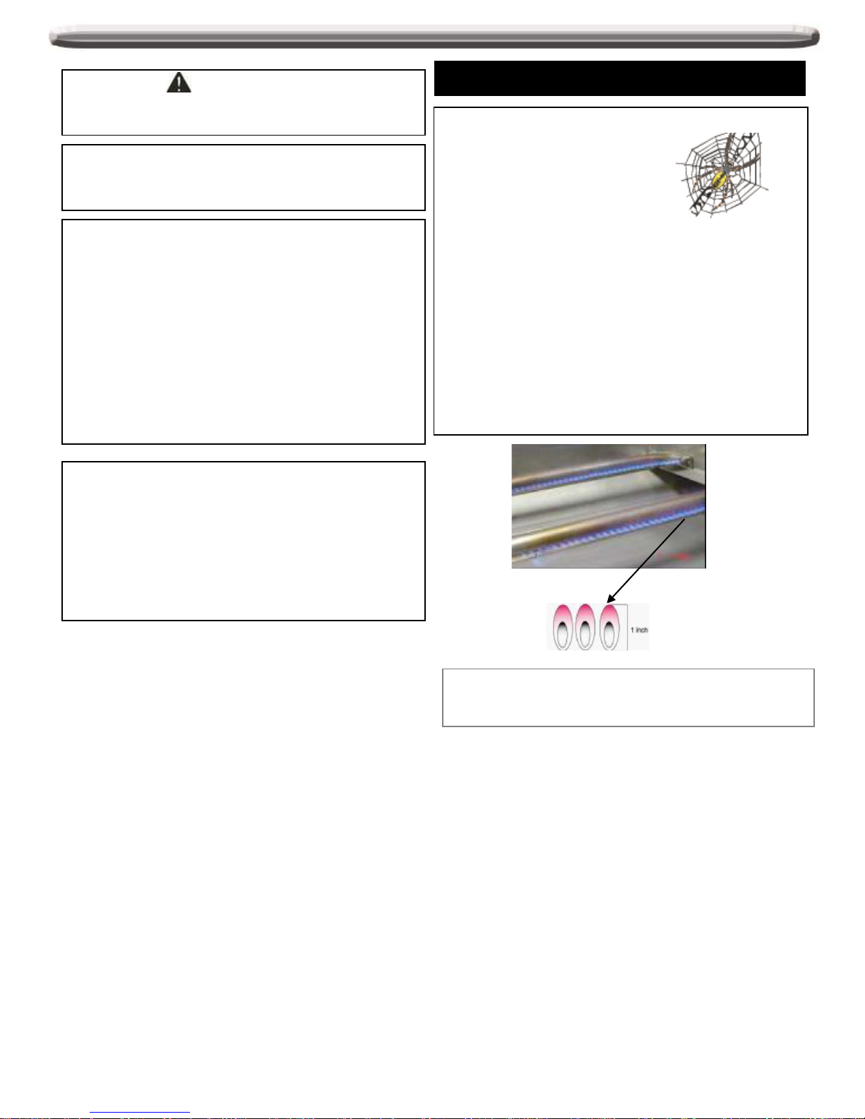
CAUTION: Spiders and small insects occasionally
spin webs or make nests in the grill
burner tubes during transit and
warehousing. These webs can lead
to gas flow obstruction, which could
result in a fire in and around burner
tubes. This type of fire is known as
“FLASH-BACK” and can cause serious damage to your grill
and create an unsafe operating condition for the user.
Although an obstructed burner t ube is not the only cause of
“FLASH-BACK”, it is the most common cause.
To reduce the chance of “FLASH-BAC K” , you must clean the
burner tubes before assembling y our grill, and at least once a
month in late summer or early fall when spiders ar e most
active. Also perform this burner tube cleaning procedure if
your grill has not been used for an extended per iod of time. A
clogged tube can lead to a fire beneath the grill.
Grill Installation Codes
Check your local building codes for the proper method of
installation. in the absence of local codes, t his unit should
be installed in accordance with the National Fuel Gas
Code ,ANSI Z223.1/NFPA 54,Storage and Handling of
Liquefied Petroleum Gases, AN SI /NFP A B149.2 or CS A
B149.1 Natural Gas and Propane I nstallation Code, and the
National Electrical Code, ANSI/NFPA 70.
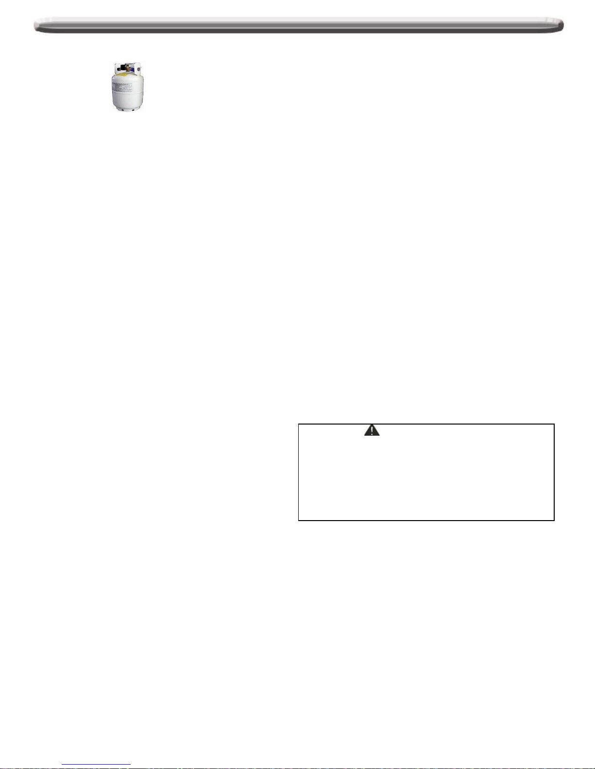
Correct LP Gas Tank Use
LP gas grill models are designed for use with a standard 20
lb. Liquid Propane Gas tank, not included with grill. Never
connect your gas grill to an LP gas tank that ex ceeds this
capacity.
NOTE: The normal flow of gas through the regulator and
hose assembly can create a humming noise. A low volume
of noise is perfectly normal and will not interfere with
operation of the grill. If humming noise is loud and
excessive you may need to purge air from the gas line or
reset the regulator ex cess gas flow device. T his purging
procedure should be done every time a new LP gas tank is
connected to your grill.
Visually check the burner flames prior to each use. The
flames should look like this picture. If they do not, refer to the
burner maintenance part of this manual.
3
Safety Instruction continued
LP-Gas Supply System
• If the information is not foll owed exactl y, a fire resulting in
death or serious injury could occ ur.
• A 20lb tank of approximately 12 i nches in diameter by 18-1/4
inches high is the maximum size LP gas tank to use.
• This safety feature prevents the tank from being overfill ed,
which can cause malfunction of the LP gas tank, regulator
and/or grill.
• The LP gas supply cylinder to be used must be construct ed
and marked in accordance with the specifications for LP –
Gas cylinder of the U.S. Department of Transportation (DOT)
or the National Standard of Canada ,CAN/CSA –B339,
Cylinders, Spheres and Tubes f or T ransportation of
Dangerous Goods and Commission .
• The LP gas tank must have a shut off valve terminating in an
LP valve outlet that is compatible with a Type 1. LP gas
supply cylinder must have a shut off valve terminating in a
valve outlet specified for connection type QCC1 in the
standard for compress ed gas cylinder valve outlet and inlet
connection ANSI/CGA -V-1 as applicable. LP gas supply
cylinder must be fitted with an Overfil l Protection Device
(O.P.D) The LP gas tank must also have a s afety relief
device that has a direct connect i on with the vapor space of
the tank.
• The tank supply system must be arranged for vapor
withdrawal.
• The LP gas tank used must have a collar to protect the tank
valve.
• Place dust cap on cylinder valve out l et whenever the cylinder
is not in use. Only install the type of dust cap on the cylinder
valve outlet that is provided with the cylinder valve. Other
types of cap or plugs may result in leakage of propane.
• Never connect an unregulated LP gas tank to your gas grill.
• This outdoor cooking gas appliance is equipped with a high
capacity hose/regulator assembly for connection to a
standard 20lb. Liquid propane cylinder.
• Have your LP gas tank filled by a reputabl e propane gas
dealer and visually inspected and re-qualified at each filling.
• Do not store a spare LP gas cylinder under or near this
appliance.
• Never fill the cylinder beyond 80 percent full.
• Always keep LP gas tanks in an upright position.
• Do not store or use gasoline or other flammable vapors and
liquids in the vicinity of this or any ot her appl i ance.
• Storage of an outdoor cooking gas appliance indoors is
permissible only if the cylinder is disconnected and removed
from the outdoor cooking gas appliance.
• When your gas grill is not in use the gas must be turned off at
LP gas tank.
• The gas must be turned off at the supply cylinder when the
outdoor cooking gas applianc e is not in use.
• LP gas tank must be stored outdoors in a well-ventilated area
and out of reach of children. Di sconnected LP gas tanks m ust
not be stored in a building, garage or any other enclosed area.
• Do Not obstruct the flow of ventilation air around the gas gril l
housing. Only use the regulator and the hose assembly
supplied with your gas grill. Replacement regulators and hose
assemblies must be those specified in this manual.
• The regulator and hose assembly must be inspected before
each use of the grill. If there i s excessi ve abrasion or wear or
if the hose is cut, it must be replaced prior to the grill being put
into operation. The replacement hose assembly shall be that
specified by the manufacturer.
• Pressure regulator and hose assembly supplied with the
outdoor cooking gas applianc e must be used. Never
substitute other types of regulator. Contact cust omer service
for manufacturer specified replacement parts.
• This outdoor cooking gas appliance is equipped with a
pressure regulator comply with the standard for Pressure
Regulating Valves for LP Gas A NS I / UL 144.
• Do not use briquettes of any k i nd i n t he gri l l .
• The grill is designed for optimum performance without the use
of briquettes. Do not place bri quettes on the radiant as this will
block off the area for the gril l burners to vent . Adding
briquettes can damage ignition components and k nobs, and
void the warranty.
• Keep the back and side c art free and clear from debris.
• Never use the grill in extremely windy conditi ons. If located in
a consistently windy area (oceanfront, mountaintop, etc.) a
windbreak will be required. Always adhere to the specified
clearance.
• Never use a dented or rusty propane tank.
• While lighting, keep your face and hands as far away from the
grill as possible.
• Burner adjustment should only be performed after the burner
have cooled.
WARNING
Your grill will get very hot. Never lean ov er the cooking area
while using your grill. Do not touch cooking sur faces, grill
housing, lid or any other grill parts w hile the grill is in
operation, or until the gas grill has cooled down after use.
Failure to comply with these instructions may result in
serious bodily injury.
PROPER PLACEMENT AND CLEARANCE OF GRILL
• Never use your gas grill in a garage, porch, shed,
breezeway or any other enclosed area. Your gas grill is
to be used outdoors only.
Do Not install this unit into combustible enclosures.
Minimum clearance from sides and back of unit t o
combustible construction, 24 inches (61cm) from sides
and 24 inches (61cm) from back.
• DO NOT use this appliance under overhead combustible
surfaces. This outdoors cooking gas appliance is not
intended to be installed in or on recreational vehicles
and/or boats.
4
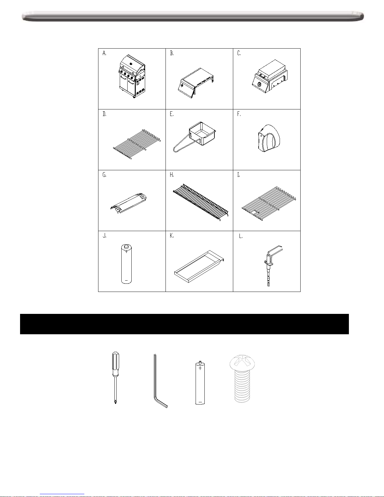
Package Parts List
Screws used to attach the parts are already pre-placed on the parts or grill body. Loosen the screws
before you install the part.
REQUIRED TOOLS & INSTALLATION EXAMPLES (screws have been atta che d on side burne r, side panel
or corresponding parts)
Firebox assembly-1pc
Left side shelf -1pc
Side burner assembly -
1pc
Cooking Grate -1pc
Sear Side Burner
Grease cup-1pc Control knob -1 pc
Flame tamer -4pcs
Warming rack -1pc
Cooking grid with hole
-3pcs
Battery - 1pc
Sear Burner Grease
Tray - 1pc
Side Burner Igniter Wire
- 1pc
5
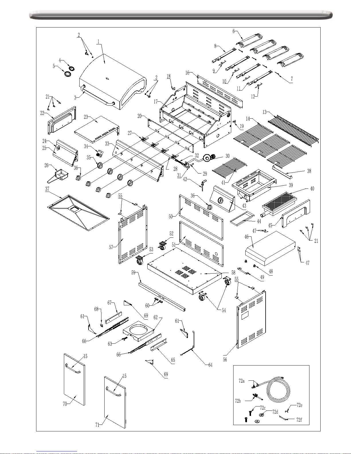
Exploded View
6

7
No. Part (Description)
Warranty
coverage (year)
QTY No. Part (Description)
Warranty coverage
(year)
QTY
1 Main lid 1 1 41 Sear side burner cooking grate 1 1
2 Main lid screw 1 2 42 Side burner ignitor wire 1 1
3 Main lid handle 1 1 43 Sear side control panel 1 1
4 Temperature gauge 1 1 44 Sear side burner grease tray 1 1
5 Temperature gauge housing 1 1 45 Side shelf trim panel, right 1 1
6 Flame tamer 1 4 46 Sear side burner lid 1 1
7 Burner pin assembly 1 4 47 Sear side burner lid screw 1 2
8 Main burner 5 4 48 Hood buffer A 1 2
9 Main burner igniter wire A 1 1 49 Sear side burner lid handle 1 1
10 Main burner igniter wire B 1 1 50 Rear panel, top 1 1
11 Main burner igniter wire C 1 1 51 Rear panel, bottom 1 1
12 Main burner igniter wire D 1 1
52 Swivel caster with brake 1 1
13 Warming rack 1 1 53 Swivel caster 1 1
14 Cooking grid 3 3 54 Caster 1 2
15 Door Handle assembly 1 2 55 Grease pan supporting brackets 1 4
16 Back panel, top 1 1 56 Side panel, right 1 1
17 Main burner bowl assembly Non-replaceable 1 57 Side panel, left 1 1
18 Lid bracket, left 1 1 58 Bottom panel 1 1
19 Lid bracket, right 1 1 59 Cart frame, front 1 1
20 Front Baffle 1 1 60 Door magnet 1 2
21 Utensil hook 1 6 61 Triangle bracket, left 1 2
22 Side shelf trim panel,left 1 1 62 Tank tray 1 1
23 Side shelf,left 1 1 63 Tank tray bolt 1 1
24 Logo 1 1 64 Lighting rod 1 1
25 Side shelf control panel 1 1 65 Tank tray slide bracket, right 1 1
26 Grease box 1 1 66 Gas tank tray slide 1 2
27 Main gas valve 1 4 67 Tank tray slide bracket, left 1 1
28 Main manifold 1 1 68 Gas tank tray block piece 1 1
29 Sear side burner gas valve 1 1 69 Triangle bracket, right 1 2
30 Regulator LP 1 1 70 Door, left 1 1
31 Side manifold 1 1 71 Door, right 1 1
32 Side burner flex gas line 1 1 72 NG conversion kit
sold separately as
set
1
33 Main control panel 1 1 72a
NG gas hose with quoick
connector assembly
sold separately as
set with #72
1
34 Pulse ignitor module 1 1 72b NG regulator assembly
sold separately as
set with #72
1
35 Bezel 1 4 72c Truss head screw with lock
sold separately as
set with #72
2
36 Control knob 1 5 72d Flat washer
sold separately as
set with #72
2
37 Grease tray 1
1 72e 6mm Nut driver
sold separately as
set with #72
1
38
Sear side burner lid support
bracket
1 1 72f 6mm Wrench
sold separately as
set with #72
1
39 Sear side burner bowl assembly 1 1 PVC cover 1 1
40 Sear side burner 1 1 Manual 1
Part List
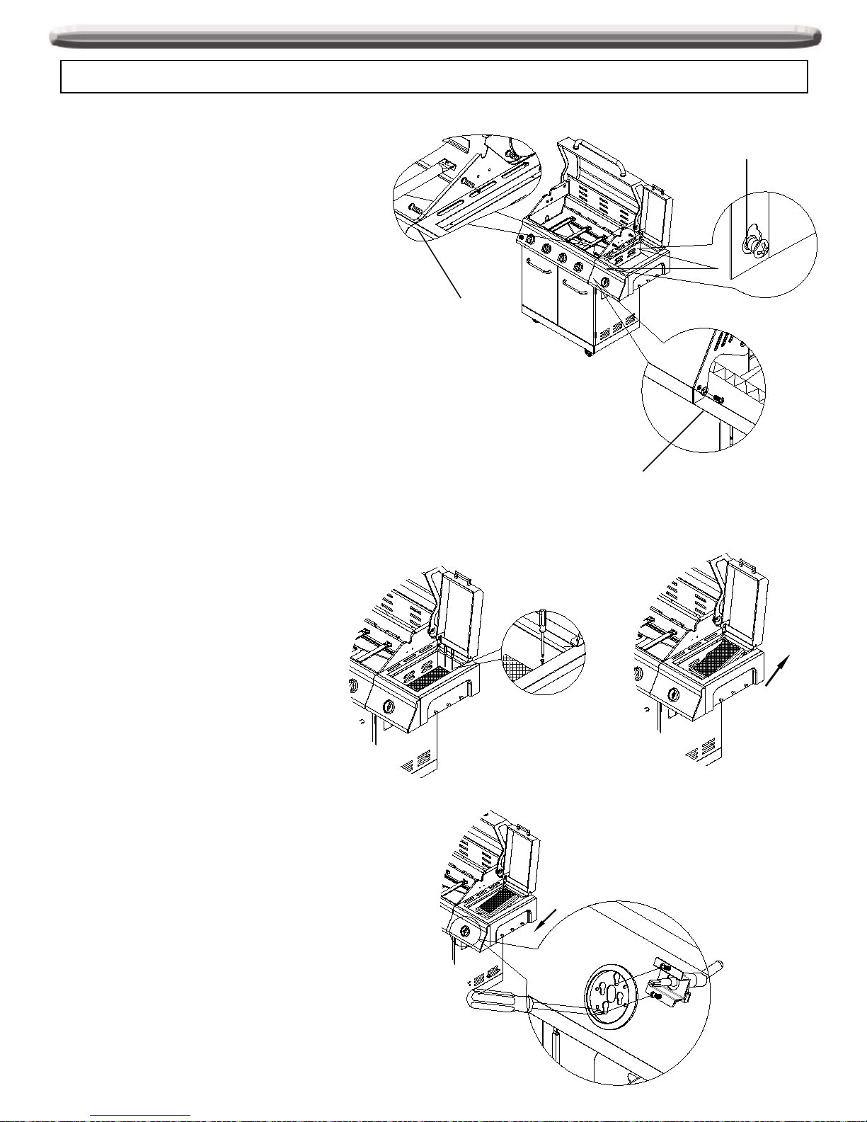
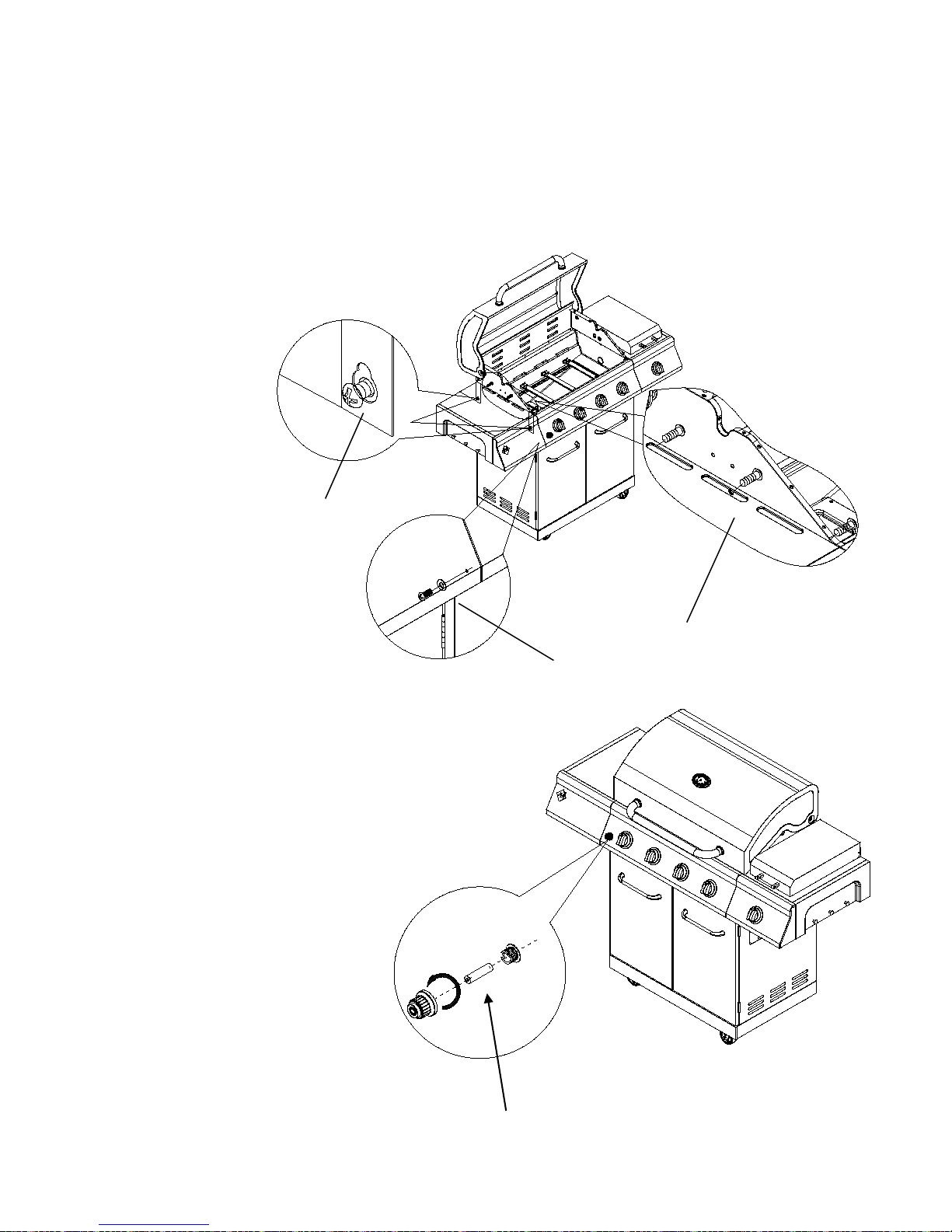
Assembly I nstruction
Tighten all screws o n the grill as some screws may have loosened during transit
Fig.1
Fig.2
1.Sear Side Burner Assembly
(a). Loosen but do not remove (A2) two screws
which are pre-assembly on the right side panel.
(b).Remove the (A1) three ¼” screws on the top
edge of the side burner bowl, align the bottom key
holes on side burner bowl with two loosened (A2)
screws on right side panel. Hang the side burner
bowl to the cart with the two loosened screws on
the side panel.
(c) Insert the (A3) 5/32” screw and 1 M4 flat
washer to attach the sear side burner shelf control
panel to the main control panel. Fully tighten the
two loosened screws to secure shelf to firebox.
See Fig.1
A2
A1
A3
8
2. Searing Side Burner Valve Assembly
a. Remove the two screws from the searing side burner,
then remove the searing side burner. See Fig.2
b) Loosen but do not remove the two M4
screws that are pre-attached to the valve.
Insert the searing side burner valve into the
searing side burner control panel and bezel.
Align the screws on the valve with the large
side of the holes on the bezel. Slide the
screws down to the smaller holes and
tighten the screws to secure.
c) Replace the searing side burner, angling
it so that the side burner tube slides over the
valve orifice. See Fig.3
Fig.3
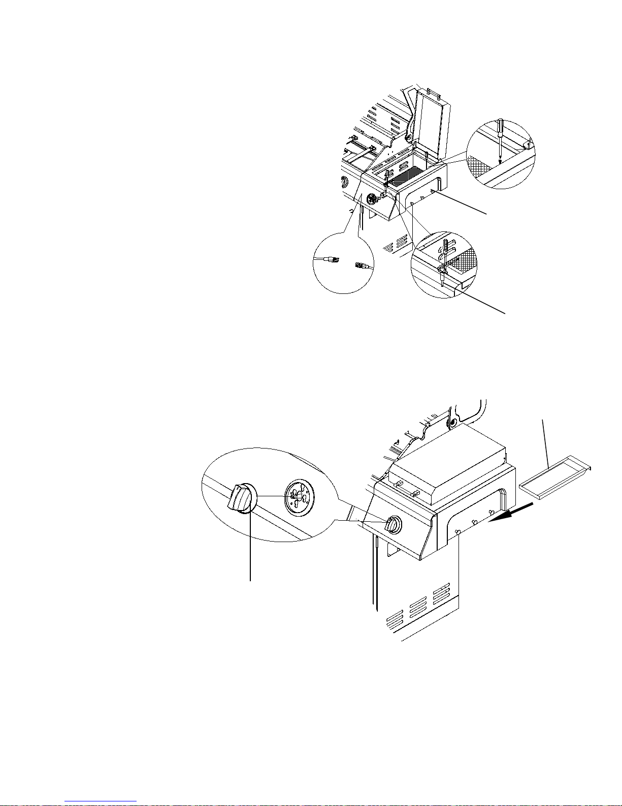
d. Tighten the two 5/32 screws
removed from step a. Loosen the one
5/32 screw at the front of the side
burner bowl (C) then align the side
burner igniter wire (L) to the hole and
tighten the screw.
C
L
Fig.4
9
e. Install the sear burner grease tray (K)
from the rear of the grill. Push control knob
(F) onto valve control stem. See Fig.5
F
K
Fig.5
3. Side Shelf Assembly
(a). Loosen but do not remove two screws (A2) which are
pre-assembled on the left side panel, then remove the
three ¼” truss head screws (A1) attached on the inside of
the left side shelf and the (A3) screw, hang the side shelf
on the two loosened screws.
(b). Using three ¼” truss head screws (A1) attach side
shelf to firebox from inside the firebox. Insert (A3) one 5/32”
truss head screw, one M4 flat washer to attach the side
shelf control panel to the main control panel. Fully tighten
all loosened screws to secure shelf to firebox. See Fig 6.
A2
A3
A1
Fig.6
10
J
4. Igniter and Battery Assembl y
a) Remove igniter cover and lock washer from
igniter. Insert igniter through from back of
side burner control panel, secure lock washer
from front of side burner control panel.
b) Install battery (J) into ignition box with
positive terminal facing panel.
c) Replace the ignition battery cap after the
battery has been install. See Fig.7
Fig.7
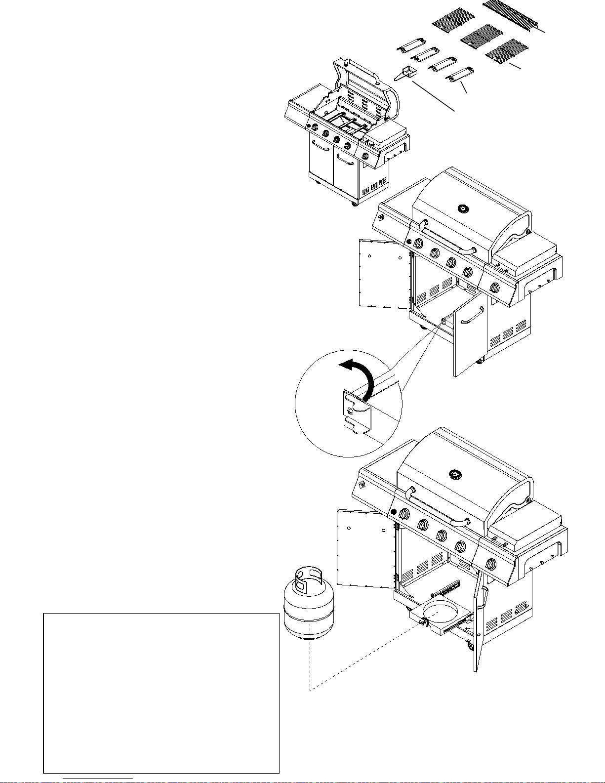
5. Flame Tamer, Cooking Grid, and Warming Rack
Assembly
a) Place flame tamer (G) over burners as shown,
ends should insert into channels on front and back of
firebox.
b) Evenly space cooking grids (I) on the ledge above
flame tamer. To obtain searing marks in cooked
meat, be sure to insert grids so that the side with
four corner feet faces down.
c) Insert legs of warming rack (H) into the holes in
the top of firebox side panels.
d) Place grease cup(E) from the rear of the grill.
See Fig 8
Notice
This grill is equipped with dual ener gy valves
and can be converted from Liquid Propane
gas supply to Natural Gas supply. Conversion
kits may be purchased through
www.samsclub.com.
For grill model # 720-0830G, the NG
conversion kit is model # 710-0677.
Please purchase the conversion kits
appropriate for your gas grill model , and
follow conversion step from page 24-27.
6. Propane Gas Tank Assembly
a)To release the tank tray glides, slide the bracket
up 90 degree.
To lock tank tray glides, slide the bracket to the left
90 degree. See Fig.9
b)Pull out of tank tray seat, place tank into the
hole in bottom panel. Use the tank bolt to secure
the tank in a fixed position, turn lock to the right.
Fig.8
Fig.9
H
I
G
E
11
Gas Hook - Up
NEVER CONNECT AN UNREGULATED GAS
SUPPLY LINE TO THE APPLIANCE. USE THE
REGULATOR/HOSE ASSEMBLY SUPPLIED.
This is a liquid propane configured grill. Do not attempt
to use a natural gas supply unless the grill has been
reconfigured for natural gas use.
Total gas consumption (per hour) of this stainless
steel gas grill with all burners on “HIGH”:
Main burner 48,000 BTU/hr
Sear burner 15,000 BTU/hr
Total 63,000 BT U/hr
L.P. TANK REQUIREMENT
A dented or rusty L.P. tank may be hazardous and
should be checked by your L.P. supplier. Never use a
cylinder with a damaged valve. The L.P. gas cylinder
must be constructed and marked in accordance with
the specifications for L.P. gas cy linders of the U .S .
Department of Transportation (DOT) or the National
Standard of Canada, CAN/CSA-B339, Cylinders,
Spheres and Tubes for Transportat ion of D angerous
Goods; and Commission, as applicable. Overfilling
prevention device (OPD) shall be provided on cylinder
& QCCI connection on the cylinder valve, ANSI/CGAV-1. The cylinder supply system must be arranged for
vapor withdrawal. The cylinder must include a collar to
protect the cylinder valve. The cylinder must be
provided with a shut off valve terminating in an L.P.
gas supply cylinder valve outlet specified, as applicable,
for connection type QCC1 in the standard for
compressed gas cylinder valve outlet and inlet
connection ANSI/CGA-V-1.
Manifold pressure: 11”(27.94cm) water column (W.C.).
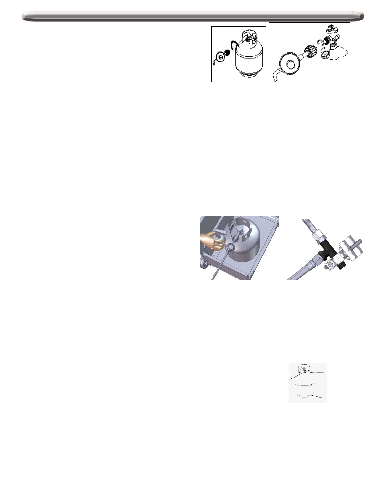
L.P. GAS HOOK-UP
Ensure that the black plastic grommets on the LP
cylinder valve are in place and that the hose does not
come into contact with the grease tray or the grill head.
CONNECTION
Your stainless steel grill is equipped with gas supply
orifices for use only with liquid propane gas. It is also
equipped with a high capacity hose/regulator assembly
for connection to a standard 20lb. L.P. cylinder (18-1/4”
(46.35cm) high, 12-1/4”(31cm) diameter). To connect
the L.P. gas supply cylinder, please follow the steps
below:
1. Make sure tank valve is in its full off position (turn
clockwise to stop).
2. Check tank valve to assure it has proper external
male threads (type 1 connection per ANSIZ21.81).
3. Make sure all burner valves are in their off position.
4. Inspect valve connections, port, and regulator
assembly. Look for any damage or debris. Remov e
any debris. Inspect hose for damage. Never attempt
to use damaged or obstructed equipment. See your
local L.P. gas dealer for repair.
5. When connecting regulator assembly to the valve,
hand tighten the quick coupling nut clockwise to a
complete stop. Do not use a wrench to tighten. U se
of a wrench may damage the quick coupling nut and
result in a hazardous condition.
6. Open the tank valve fully (counterclockwise). Apply
the soap solution with a clean brush to all gas
connections. See below. I f grow ing bubbles appear
in the solution the connections are not proper ly
sealed. Check each fitting and tighten or repair as
necessary.
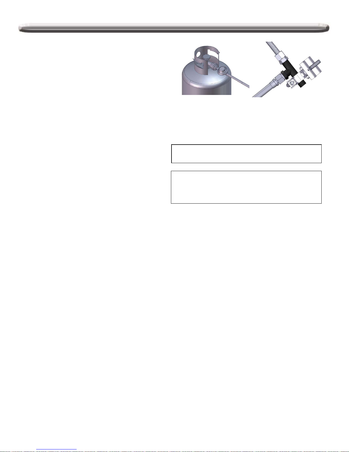
7. If you have a gas connection leak you cannot repair,
turn gas OFF at supply tank, disconnect fuel line
from your grill and call 1-888-301-0332 or your gas
supplier for repair assistance.
8. Also apply soap solution to the tank seams. See
below. If growing bubbles appear, shut tank OFF
and do not use or move it! Contact an LP gas
supplier or your fire department for assistance.
To disconnect L.P. gas cylinder:
1. Turn the burner valves off.
2. Turn the tank valve off fully (turn clockwise to stop).
3. Detach the regulator assembly from the tank valve by
turning the quick coupling nut counterclockwise.
12
Leak Testing
GENERAL
Although all gas connections on the grill are leak
tested at the factory prior to shipment, a complete gas
tightness check must be performed at the installation
site due to possible mishandling in shipment, or
excessive pressure unknowingly being applied to the
unit. Periodically check the whole system for leaks
following the procedures listed below. If the smell of
gas is detected at anytime you should immediately
check the entire system for leaks.
BEFORE TESTING
Make sure that all packing material is removed from
the grill including tie-down straps.
DO NOT SMOKE WHILE LEAK TESTING.
NEVER PERFORM LEAK TEST WITH AN OPEN
FLAME.
Make a soap solution of one part liquid detergent and
one part water. You will need a spray bottle, brush, or
rag to apply the solution to the fittings. For the initial
leak test, make sure the L.P. cylinder is 80% full.
TO TEST
1. Make sure the control valves are in the “OFF”
position, and turn on the gas supply.
2. Check all connections from the LP gas
regulator and supply valve up to and including
the connection to the manifold pipe assembly
(the pipe that goes to the burners). Soap
bubbles will appear where a leak is present.
3. If a leak is present, immediately turn off the gas
supply and tighten the leaky fittings.
4. Turn the gas back on and recheck.
5. Should the gas continue to leak from any of the
fittings, turn off the gas supply and contact
customer service at 1-888-301-0332.
ALWAYS CHECK FOR LEAKS AFTER EVERY L.P.
TANK CHANGE
Check all gas supply fittings for leaks before each
use. It is han d y to keep a spray bottle of soapy
water near the shut-off valve of the gas supply li n e.
Spray all the fittings. Bubbles indicate leaks.
Only those parts recommended by the manufacturer
should be used on the grill.
Substitution will void the warranty. Do not use the grill
until all connections have been checked and do not leak.
13

Operating Instructions
GENERAL USE OF THE GRILL
Each main burner is rated at 12,000 Btu/hr. The main
grill burners encompass the entire cooking area and
are side ported to minimize blockage from falling
grease and debris. The igniter knobs are located on
the lower center portion of the valve panel. Each rotary
igniter is labeled on the control panel.
NOTE: The hot grill sears the food, sealing in the juices.
The more thoroughly the grill is preheated, the faster
the meat browns and the darker the grill marks.
DO NOT LEAVE THE GRILL UNATTENDED WHILE
COOKING.
Grill Lighting Instructions
WARNING: IMPORTANT!
BEFORE LIGHTING…
Inspect the gas supply hose prior to turning the gas
“ON”. If there is evidence of cuts, wear, or abrasion,
it must be replaced prior to use. Do not use the grill
if the odor of gas is present. Only the pressure
regulator and hose assembly supplied with the unit
should be used.
Never substitute regulators and hose assembly for
those supplied with the grill. If a replacement is
necessary, contact the manufacturer for proper
replacement. The replacement must be that
specified in the manual.
WARNING: Always keep your face and body as
far away from the burner as possible when
lighting.
TO LIGHT THE MAIN BURNER
Make sure all knobs are “OFF” then turn on the gas
supply from the LP (Liquid Propane) tank. Always
keep your face and body as far from the grill as
possible when lighting.
To light your main burner, push and turn main
burner control knob to IGNITE/HIGH, at the same
time, press and hold electronic ignition button to
light the burner. Once the burner is lit, release the
electronic ignition button and knob. If the burner
does not light wait 5 minutes for any excess gas to
dissipate and then retry.
TO MATCH LIGHT THE GRILL
If the burner will not light after several attempts then the
burner can be match lit.
Match light extension rod is located on the inside panel of
the door.
If you’ve just attempted to light the burner with the igniter,
allow 5 minutes for any accumulated gas to dissipate.
Keep your face and hands as far away from the grill as
possible.
Insert a lit match attached to the lighting rod through the
cooking grids to the burner.
Press the control knob and rotate left to the HIGH/ON
setting continue to press the knob until the burner ignites.
Burner should light immediately.
If the burner does not light in 5 seconds turn the knob off,
wait 5 minutes and try again.
TO LIGHT THE SEARING SIDE BURNER
To light the searing side burner, remove any cooking
utensils from the burner grate. Push and turn the control
knob to “IGNITE/HIGH”, at the same time, press and hold
electronic ignition button to light the burner . Once the
burner is lit, release the electronic ignition button and
knob. If the burner does not light, turn the control knob to
“OFF”. If the smell of gas is detected and the igniter is not
functioning, immediately turn the control knob “OFF”.
Allow 5 minutes for any accumulated gas to dissipate. If
the side burner igniter is not functioning, see the following
section for match lighting.
USING THE GRILL
Grilling requires high heat for searing and proper
browning. Most foods are cooked at the “HIGH” heat
setting for the entire cooking time. However, when grilling
large pieces of meat or poultry, it may be necessary to
turn the heat to the lower setting after the initial browning.
This cooks the food through without burning the outside.
Foods cooked for a long time or foods basted with a
sugary marinade may need the lower heat setting near
the end of the cooking time.
NOTE: This grill is designed to grill efficiently without the
use of lava rocks or briquettes of any kind. Heat is
radiated by the stainless steel flame tamers positioned
above each burner.
Do not attempt to light the gri ll if odor of gas is
present. Call for service at 1-888-301-0332.
14

Lighting Instructions
Note: Remove all packaging, including straps, before using the grill
Make sure the lid is open.
If burner does not light within 5 seconds, turn the knob
to OFF and repeat the lighting instruction.
If burner does not light up after step 3, turn the knob to
OFF, wait 5 minutes, and repeat the lighting procedure
or light by match.
1
2
3
4
Main Burners
IGNITE / HI
LO
OFF
IGNITE / HI
LO
IGNITE / HI
LO
OFF
1
3
2
IGNITE / HI
LO
IGNITE / ON
1
2
OFF OFF OFF
IGNITE / HI
LO
IGNITE / HI
LO
OFF
Sear Burner
Match light
1.
If the burner will not light after several
attempts then the burner can be match lit,
before using the match allow 5 minutes for
any accumulated gas to dissipate.
2. Clip a paper match on one end of the
lighting rod.
3.
Light match.
4. Hold lighting rod and insert lighted match
right next to the burner ports or ceramic file.
5. Push and turn the designated control knob
to IGNITE/HIGH.
6. Burner should ignite immediately.
Lo
OFF
IGNITE / HI
15
Push and turn the control knob to “IGNITE/HIGH”, at the
same time, press and hold electronic ignition button to
light the burner. Once the burner is lit, release the
electronic ignition button and knob.
Care and Maintenance
STAINLESS STEEL
There are many different stainless steel cleaners available.
Always use the mildest cleaning procedure first, scrubbing in
the direction of the grain. Do not use steel wool as it will
scratch the surface. To touch up noticeable scratches in the
stainless steel, sand very lightly with dry 100 grit emery paper
in the direction of the grain. Specks of grease can gather on
the surfaces of the stainless steel and bake on to the surface
and give the appearance of rust. For remov al use a mild
abrasive pad in conjunction with a stainless steel cleaner.
GRILL GRATE
The easiest way to clean the grill is immediately after cooking
is completed and after turning off the flame. Wear a barbeque
mitt to protect your hand from the heat and steam. D ip a brass
bristle barbeque brush in water and scrub the hot grill. D ip the
brush frequently in the bowl of water. Steam, created as water
contacts the hot grill, assists t he cleaning process by softening
any food particles. If the grill is allowed to cool before cleaning,
cleaning will be more difficult.
ENSURE THAT THE GAS SUPPLY AND THE KNOBS ARE
IN THE “OFF” POSITION. MAKE SURE THE RANGE TOP
BURNER IS COOL BEFORE REMOVAL.
GRILL BURNERS
Extreme care should be taken w hen moving a burner as it
must be correctly centered on the or ifice before any attempt is
made to relight the grill. Frequency of cleaning will depend on
how often you use the grill.
MAIN GRILL BURNER CLEANING
Ensure the gas supply is off and the knobs are in the “OFF”
position. Make sure the grill is cool. Clean the exterior of the
burner with a wire brush. Clear stubborn scale with a metal
scraper. Clear any clogged ports with a straightened paper
clip. Never use a wooden toothpick as it may break off and
clog the port. Please note if insects or other obstructions are
blocking the flow of gas through the burner, and if so you will
need to call our customer service line at 1-888-301-0332.
GREASE TRAY CLEANING
The grease tray should be emptied and wiped down
periodically and wash with a mild detergent and warm water
solution. A small amount of sand may be placed in bottom of
grease tray to absorb the grease. Check the grease tray
frequently, do not allow ex cess grease t o accumulate and
overflow out of the grease tray .
BURNER CLEANING
1. Turn off the gas supply, and make sure all the knobs are
in the “OFF” position.
2. Wait for the grill to cool.
3. Clean the exterior of the burner with a wire brush. Use
a metal scraper to stubborn stains.
4. Clear clogged port with a straightened paper clip. Never
use a wooden toothpick as it may break off and clog the
port.
5. If inserts or other obstructions are blocking the flow of
gas through the burner, call customer service at 1-888301-0332.
Warning: If you wish to replace main burner, we
strongly recommend that you hire a
professionally trained technician to replace it.
Please understand that we will not be responsible
for any liability, personal injury, or property
damage res u lting from an improperly ass embled
burner.
HOW TO REPLACE MAIN BURNER
Step 1. Insert the burner onto the orifice. As shown below,
make sure burner hole aim at orifice .
Step 2. Secure the main burner on the back wall of firebox
with 1 pin and secure it at the front of fire box with 1 screw.
16

T rouble Shooting
SPIDER AND INSECT WARNING
WHEN TO LOOK FOR SPIDERS
You should inspect the burners at least once a year or immediately after any of the following conditions occur:
1. The smell of gas in conjunction with the burner flames appearing yellow.
2. The grill does not reach temperature.
3. The grill heats unevenly.
4. The burners make popping noises.
BEFORE CALLING FOR SERVICE
If the grill does not function properly, use the following check list before contacting your dealer for service. You may save the
cost of a service call.
PREHEATING: The grill lid should be in a closed position during the preheat time period. I t is necessary to pr eheat the gr ill
before cooking certain foods, depending on the type of food and the cooking temperature. Food that requires a high cooking
temperature needs a pre-heat
period of five minutes; food that requires a lower cooking temperature needs only a period of two to three minutes.
COOKING TEMPERATURES
High setting-Use this setting for fast warm-up, for searing steaks and chops, and grilling.
Low setting-Use this setting for all roasting, baking, and when cooking very lean cuts such as fish.
These temperatures var y with the outside t emperature and the amount of wind.
Cooking with indirect Heat: Y ou can cook poultry and large cuts of meat slowly to perfection on one side of the grill by indirect
heat from the burner on the other side. Heat f rom the lighted burner circulates gently throughout the grill, cooking the meat or
poultry without any direct flame touching it. This method greatly reduces flare-ups when cooking extra fatty cuts, because
there is no direct flame to light the fats and juices that drip down during cooking.
CAUTION: If burners go out during operation, close gas supply at source, and turn all gas valves off. Open lid and wait five
minutes before attempting to re-light (this allows accumulated gas fumes to clear).
CAUTION: Should a grease fire occur, close gas supply at source, turn of f all burners and leav e lid closed until fire is out.
CAUTION: DO NOT attempt to disconnect any gas fitting w hile your grill is in operation. As w ith all appliances, proper care
and maintenance will keep them in top operating condition and prolong their life. Your gas gill has no exception.
CAUTION: Side burner lid will get hot if used when lid is closed.
17

Trouble Shooting continued
PROBLEM SOLUTION
When attempting to light my grill, it
will not light immediately.
Make sure you have a spark while you are trying to light the burner (if no
spark) .
Ensure that the wire is connected to the electrode assembly.
Clean wire (s) and / or electrode with rubbing alcohol and a clean swab.
Wipe with a clean cloth.
Check to see if the other burners operate. If so, check the gas orifice on
the malfunctioning burner for an obstruction.
Regulator makes noise. Vent hose on the regulator may be plugged or regulator may be faulty.
Ensure the vent hole on the regulator is not obstructed. Clear the hole,
close the gas control valves. Wait ten minutes and restart.
Check your flames for proper performance. If the flames are not correct,
replace regulator.
Full size cover does not fit the grill. Cover may be incorrect for your grill. It may be a tight fit.
Ensure the cover is the correct length for your grill.
Measure it left to right. Compare to the grill’s measurement.
Compare the location and size of the hood portion of the cover to your
grill.
Spread the cover and allow it to relax, preferably in warm sunlight or in a
warm room.
For grill with a side shelf bunch the cover like a sock, put on left to right.
Grill only heats to 200-300 degrees. Check to see if the fuel hose is bent or kinked.
Make sure the grill area is clear of dust.
Make sure the burner and orifices are clean.
Check for spiders and insects.
The regulator has a safety device that restricts the flow of gas in the
event of a leak. This safety device can be triggered without a gas leak.
To reset the safety device, turn off all burners and close the LP tank
valve. Disconnect the regulator from the LP tank and wait one minute.
Reconnect the regulator to the LP tank and slowly open the LP tank
valve until the valve is fully open. Light all burners and observe the
temperature.
Grill takes a long time to preheat. Normal preheat 500-600 degrees, takes about 10-15 min. Cold weather
and wind may effect your preheat time.
If you are using volcanic rock or briquettes they can increase the preheat
time and maximum temperature.
Burner flames are not light blue. Too much or not enough air for the flame.
Elevation is the principal cause, however cold weather can affect the
mixture. Burner adjustment may be required.
Grill is in a windy location.
18

Ordering Parts
HOW TO ORDER REPLACEMENT PARTS
To make sure you obtain the correct replacement part (s)
for your gas grill, please refer to the parts list on pages
7-9. The following information is required to assure
getting the correct part. Please note the shipping cost for
the delivery of any replacement parts will be on yourself.
•Gas grills model number (see data sticker on grill).
•Part number of replacement part needed.
•Description of replacement part needed.
•Quantity of parts needed.
To obtain replacement parts, contact Member’s Mark
Customer Relations at:
1-888-301-0332
IMPORTANT
Use only factory authorized parts. The use of any part
that is not factory authorized can be dangerous. This will
also void your warranty.
Keep this assembly and operating instruction manual for
convenient referral, and for replacement parts ordering.
CAUTION
Gas valves are present at the factory (valve assembly
will be marked accordingly). If you wish to convert at
some later date, be sure to contact your gas supplier or
grill dealer before making the conversion.
Different orifices must be installed when converting from
one type of gas to another. You will also need a data
plate indicating what type of gas is used by the grill.
Grill Hints
The doneness of meat, whether rare, medium, or
well done, is affected to a large degree by the
thickness of the cut. Expert chefs say it is
impossible to have a rare doneness with a thin cut
of meat.
The cooking time is affected by the kind of meat,
the size and shape of the cut, the temperature of
the meat when cooking begins, and the degree of
doneness desired.
When defrosting meats it is recommended that it
be done overnight in the refrigerator as opposed to
a microwave. This in general yields a juicier cut of
meat.
Use a spatula instead of tongs or a fork to turn the meat, as
a spatula will not puncture the meat and let the juices run
out.
To get the juiciest meats, add seasoning or salt after the
cooking is finished on each side and turn the meat only
once (juices are lost when the meat is turned several
times). Turn the meat just after the juices begin to bubble
to the surface.
Trim any excess fat from the meat before cooking. To
prevent steaks or chops from curling during cooking, slit
the fat around the edges at 2-inch intervals.
DO NOT LEAVE THE GRILL UNATTENDED WHILE
COOKING.
Grill Cooking Chart
FOOD
WEIGHT OR
THICKNESS
HEAT
SETTING
APPROXIMATE
TIME
SPECIAL INSTRUCTIONS
AND TIPS
VEGETABLES
Slice. Dot with butter or margarine. Wrap in
heavy -duty foil. Grill, turning occasionally.
Fresh Beets Carrots
Turnips Medium 12 to 20 minutes
Grill, turning once. Brush occasionally with
melted butter or margarine.
Onion 1/2 inch slices Medium 8 to 20 minutes
Season with Italian dressing, butter, or
margarine.
Potatoes Sweet
White
Whole
6 to 8 ounces
Medium
High
40 to 60 minutes
45 to 60 minutes
Wrap individually in heavy - duty foil. Grill,
rotating occasionally.
Frozen Asparagus
Peas Green beans
Sprouts Medium 15 to 30 minutes
Dot with butter or margarine.
Wrap in heavy -duty foil. Grill, turning
occasionally.
19

Grill Cooking Chart continued
FOOD
WEIGHT OR
THICKNESS
HEAT
SETTING
APPROXIMATE
TIME
SPECIAL INSTRUCTIONS
AND TIPS
French fries Medium 15 to 30 minutes
Place in aluminum foil pan.
Grill, stirring occasionally
MEATS BEEF
Hamburgers
1/2 to 3/4 inch
Medium
10 to 18 minutes
Grill, turning once when juices rise to the surfaces.
Do not leave hamburgers unattended since a
flare-up could occur quickly. Cook to internal
temperature of 160 degrees
Tenderloin High 8 to 15 minutes
Rare 1 inch High 8 to 14 minutes
Trim edges. Grill, turning once
Medium
1-1/2 inch
1 inch
1-1/2 inch
High
Medium
to High
11 to 18 minutes
12 to 22 minutes
16 to 27 minutes
Well - done
1 inch
1-1/2 inches
Medium
Medium
18 to 30 minutes
16 to 35 minutes
LAMB
Chop & Steaks
Rare
1 inch
1-1/2 inch
Medium
to
High
10 to 15 minutes
14 to 18 minutes
Trim edges. Grill, turning once.
Medium
1 inch
1-1/2 inch
Medium
to
High
13 to 20 minutes
18 to 25 minutes
PORK
Chops
1 inch
Medium
20 to 30 minutes
Trim edges. Grill, turning once. C ook to desired
doneness.
Well-done 1 -1/2 inches Medium 30 to 40 minutes
Ribs
Medium
30 to 40 minutes
Grill, turning occasionally.
During last few minutes brush with barbecue
sauce. Turn several times.
Ham steaks
(precooked)
1 inch slices
High
4 to 8 minutes Trim edges. Grill, turning once.
Hot dogs Low 5 to 10 minutes Slit skin. Grill, turning once.
POULTRY
2 to 3 pounds
Low
or
Medium
Up to 1 hour
Place skin side up. Grill, turning and brushing
frequently with melted butter, margarine, oil or
marinade.
Breasts
well –done
Medium
30 to 45 minutes Marinate as desired.
FISH AND
SEAFOOD
Halibut
Salmon
Swordfish
3/4 to 1 inch
Medium
to
High
8 to 15 minutes
Grill, turning once. Brush with melted butter,
margarine or oil to keep moist.
Whole
Catfish
Rainbow trout
4 to 8 ounce
Medium
to
High 12 to 20 minutes
Grill, turning once. Brush with melted butter,
margarine or oil. Brush with melted butter and
lemon juice.
20

Grill Recipe Suggestion
BBQ SALMON
2 large salmon steaks
2 tbs. Oil
Salt & pepper
2 oz. thin bacon slices
2 tbs. Butter
1 tbs. Lemon juice
Spring of parsley
Lemon wedges
Preheat the BBQ.
Brush the steaks with oil and season
with salt and pepper. Place on BBQ grill
and cook for 10 minutes, turning steaks
over halfway through cooking time.
Meanwhile fry the bacon in a pan on
the side burner. Drain on paper towels.
Meld the butter in a small saucepan
taking care not to discolor it. Arrange
the fish and bacon on serving plates.
Pour the butter over and sprinkle with
lemon juice. Garnish with parsley
springs and lemon wedges. Ser v e with
boiled potatoes tossed in butter and
sprinkled with chopped parsley and a
crisp lettuce salad.
Note: Substitute catfish, halibut or cod
for salmon.
BAKED CHILI CORN
6 medium ears corn, husked
3 tbs. Butter or margarine, melted
Dash ground cumin
Dash ground coriander
About ½ hour before cooking, turn the
butter on for grill. Place each corn on a
heavy-duty foil. In a bowl, combine
remaining ingredients. Mix well. Brush
1-1/2 tsp. Butter mixture over each ear.
Close foil and fold up ends to seal.
Place on grill. Cook, turning packets
occasionally 10 to 12 minutes or until
cooked through.
TANGY SEAFOOD KABOBS
1 lb. Large shrimp, shelled & deveined
¾ lbs. sea scallops
2/3 c. chili sauce
¼ c. cider vinegar
butter and sprinkled with chopped
parsley and a crisp lettuce salad.
In medium bowl, combine shrimp and
scallops. In small bowl combine chili
sauce and next six ingredients. Pour
over seafood. Toss to coat.
Cover, refrigerate 2 hours.
3 tbs. chopped parsley
1 tbs. vegetable oil
1 tbs. Worcestershire sauce
½ tsp. prepared horseradish
1 cove garlic, minced
1 20 oz. Can pineapple chunks in juice,
drained half hour before cooking, turn
the burner to the grill on full. Drain
seafood reserving marinade. On each
of twelve 10” skewers, thread 2 shrimps
and 2 scallops, alternating with
pineapple chunks. Place skewers on
grill. Cook 7-10 minutes, often basting
and turning.
PORK CHOPS
4 Pork chops
Marinade
1 large onion
2 tbs. lemon juice or vinegar
2 tbs. oil
½ tsp. powdered mustard
2 tsp. Worcestershire sauce
½ tsp. freshly ground black pepper
1 tsp. sugar
½ tsp. paprika
1 clove garlic
Peel, grate onion, and add rest of the
ingredients ex cept the pork chops. Mix
well. Pour over chops and marinate one
hour in a cool place. Turn the BBQ grill
on full. Heat 10 minutes.
BBQ the chops brushing w ith the
marinade occasionally. Serve with
mixed salad, dressed with vinaigrette
flavored with fresh dill.
BARBECUED LONDON BROIL
4 to 6 servings
¾ c. Italian dressing
1 tsp. Worcestershire sauce
1 tsp. dry mustard
¼ tsp. thyme, crushed
1 medium onion, sliced
1 pound flank steak, scored
2 tbs. butter, melted
Combine first 4 ingredients, add onion
and marinade flank steak with it.
Refrigerate at least 4 hours or
overnight. Remove steak and grill on
your preheated BBQ grill. Grill 5 to 7
minutes on each side basting
frequently with the marinade. In the
meantime sauté onions from the
marinade in butter in a skillet on your
side burner for 3 minutes. To serve,
slice steak diagonally into thin slices,
sprinkle onions over top. G arnish w ith
vegetable kabobs.
BARBECUED POTATOES and
CHEESE
1-1/2 cups shredded cheddar cheese
1 can (10-3/4 oz.) condensed cream
of mushroom soup
1/3 cup milk
2 tbs. barbecue sauce
¼ tsp. oregano
¼ tsp. salt
1/8 tsp. pepper
4 cups thinly sliced potatoes (4
medium-sized potatoes)
Preheat grill. Combine cheese,
condensed soup, milk, BBQ sauce,
oregano, salt and pepper in a large
mixing bowl. Stir in potatoes until w ell
coated. Turn into well buttered1-1/2
quart rectangular baking dish. Cover
dish with aluminum foil. Bake covered
25 minutes on medium with the lid of
your BBQ grill closed. Remove foil
and continue baking 15 minutes
longer or until potatoes are tender. Let
stand 5 minutes before serving.
VEGETABLE KABOBS
3 medium-sized zucchini
12 cherry tomatoes
12 fresh mushrooms
Grated Parmesan cheese
Parboil whole zucchini 5 minutes on
your side burner or until just tender.
Drain and cut into ½ inch slices.
Thread zucchini, tomatoes and
mushrooms alternately on each of six
skewers. Brush with marinade made
of Italian dressing, Worcestershire
sauce, mustard and thyme. Gr ill 5 to 7
minutes turning and basting
occasionally. Sprinkle liberally w ith
Parmesan cheese.
21

Grill Recipe Suggestion continued
FAJITAS
1-1/2 lb. flank steak or boned chicken
breasts
2 tbs. oil
½ cup limejuice
½ tsp. salt
½ tsp. celery salt
¼ tsp. garlic powder
½ tsp. pepper
¼ tsp. oregano
¼ tsp. cumin
Flour tortillas lemon
Pound flank steak to ¼ inch thickness
or flatten chicken breasts. Mix oil, lime
juice and seasonings in a zip lock bag.
Add meat and shake bag to coat the
meat. Refrigerate overnight or at least 6
to 8 hours. Wrap tortillas in foil.
Remove meat from marinade. Cook on
a pre-heated gas grill for 5 to 8 minutes
on each side. While meat is cooking,
heat tortillas on grill. Slice meat across
grain in thin slices. Place on hot platter.
Squeeze lemon juice over. Wrap meat
and any of the following toppings in
tortillas: chopped tomatoes, guacamole,
sour cream, taco sauce.
BEEF AND LAMB KABOBS
Serve 4
½ lb. boneless sirloin or beef cut into 1”
cubes
½ lb. boneless loin of lamb cut into 1”
cubes
2/3 c. water, divided
¼ c. chopped onion
2 tbs. soy sauce
¼ c. vegetable oil, divided
1 tbs. dark brown sugar
1 tbs. fresh lemon juice
2 cloves garlic, minced
¼ tsp. ground cumin
¼ tsp. ground coriander
¼ tsp. ground turmeric
1/8 tsp. ground red pepper
1/8 tsp. ground ginger
1 red pepper cut into chunks
1 large banana, cut into chunks
8 small mushrooms
1/3 c. smooth peanut butter
In blender, process 1/3 c. water, onion,
soy sauce, 2 tsp. oil and the next 8
ingredients until smooth. P our ov er
meat cubes and marinate about 4 hours,
turning occasionally. Drain and r eserv e
marinade. Onto to four 12” skewers
alternately thread meat, pepper,
banana and mushrooms. Preheat grill.
Brush the kabobs with oil. Grill 7-8
minutes each side.
Bring marinade to boil on the side
burner in a saucepan. Add remaining
1/3 c. water and peanut butter. Stir to
blend. Heat through. If sauce gets too
thick, add 1 tbs. water. Serve sauce
with kabobs.
EGGPLANT CAVIAR
1 large eggplant
2 tbs. olive oil
2 tbs. wine vinegar
2 tbs. finely chopped onion
½ clove garlic, minced
1 medium tomato, chopped salt and
pepper
Roast eggplant on gas grill over
medium flame, turning occasionally
until thoroughly cooked. This may take
30 minutes. Remove from grill and cool
for handling. Strip off the skin and chop
eggplant finely. Add all the seasonings.
Chill thoroughly and serve on toast.
CHICKEN TANDOORI STYLE
8 large chicken thighs or drumsticks
1 c. plain nonfat yogurt
½ c. lemon juice
2 tsp. salt
½ tsp. cayenne
½ tsp. black pepper
½ tsp. crushed garlic
½ tsp. grated ginger
1 tbs. corn oil
Combine all the ingredients in a large
mixing bowl and marinate the chicken
for 8 hours in the refrigerator. Drain the
chicken and spread on the spit running
the rod on the fleshier side of the bone.
Roast using the rotisserie burner. Cook
on medium high heat for 40 minutes
basting occasionally with the remainder
of the marinade mixture. Serve with
sliced onions and lemon wedges.
SPARE RIBS
Marinade:
1 c. soy sauce
½ c. honey
½ c. vinegar
½ c. dry sherry
2 tsp. chopped garlic
2 tsp. sugar
1 c. water
1 chicken bouillon cube
1 can beer for basting sauce
Marinade ribs for 3 hours. Use
marinade for basting by adding beer
to it. Place pan under the ribs and
baste frequently. To cook ribs select
lean, meaty ribs and accordion pleat
them with your spit. Slide four prong
meat hook down the length of spit and
tighten. At the beginning of
the rack and to its center, penetrate
the second rib with the pointed end of
the spit and push it between the meat.
Skip a couple and continue the
process until the entire rack is
accordion pleated. Fasten the second
meat hook into the rack. Turn your
rotisserie burner on high. Roast for
50 minutes or until done.
PORK ROAST
Apple cider vinegar basting sauce:
1 c. apple cider vinegar
6 oz. water
½ stick butter
Salt, pepper, parsley and garlic
seasoning
2 oz. lemon juice
10 lbs. pork roast
Time: 1-1/2 hours to 2 hours
Bring pork to room temperature before
placing it on the spit rod. Place on the
rod and test for balance. Light
rotisserie burner. Turn control knob to
high. Use the above basting sauce for
rotissing .
TURKEY
12 lb. turkey
Beer basting sauce:
1 can beer
12 oz. water
1 stick butter
1 tsp. salt
1 tsp. pepper
½ tsp. garlic flakes
1 tsp. parsley
Thaw the bird completely. Wash
inside out. Securely tie the legs and
wings. Light rotisserie burner. Turn to
high. Combine all the ingredients for
basting sauce in a shallow pan. Place
it under the turkey 15 to 20 minutes.
Cook for approximately 3 hours. T he
basting sauce combined with turkey
drippings makes a delicious gravy.
22

Limited W arra nty
Member’s Mark warrants to the original consumer-purchaser only that this product (Model #720-0830G) shall be free from defects in
workmanship and materials after correct assembly and under normal and reasonable home use for the periods indicated below beginning on
the date of purchase. The manufacturer reserves the right to require photographic evi dence of damage, or that defective parts be returned,
postage and or freight pre-paid by t he cons um er, for review and examination.
Burners: 5 year LIMITED warranty against perforation
Grids, grates & electronic igniti on: 3 year LIMITED warranty
* Does not cover dropping, chipping, sc rat ching or surface damage
Stainless steel parts: 1 year LIMITED warranty against perforation
* Does not cover cosmetic issue like surface corrosion, scratched and rust
All other parts: 1 year LIMITED warranty
* Does not cover chipping, scratching, cracking surface corrosion, scratc hes or rust
Upon consumer supplying proof of purchase as provided herein, Manufacturer will repair or replace the parts which are proven defective
during the applicable warranty period. Parts required to complet e such repair or replacement shall be free of charge to you except for
shipping costs, as long as the purchaser is within the warranty period from the original date of purchase. The original consumer-purchaser
will be responsible for all shipping charges of parts replaced under the terms of this limited warranty. This limited warranty is applicable in
the United States only, is only available to the original owner of the product and is not transferable. Manufac turer requires reasonabl e proof
of your date of purchase. Theref ore, you should retain your sales receipt and/or invoice. If the unit was received as a gift, please ask the giftgiver to send in the receipt on your behal f, to the below address . Defective or missi ng parts subjec t to t hi s limited warranty will not be
replaced without registration or proof of purchase. This limited warranty applies to the funct i onal i t y of the product ONLY and does not cover
cosmetic issues such as scratches, dents, corrosions or discoloring by heat, abrasive and chemi cal cleaners or any tools used in the
assembly or installation of the appli ance, surface rust, or the discoloration of stainles s steel surfaces. Surface rust, cor rosion, or powder
paint chipping on met al parts that does not affect t he s tructural integrity of the produc t i s not considered a defect i n work manship or material
and is not covered by this warranty. This limited warranty will not reimburse you for the cost of any inconvenience, food, personal injury or
property damage. If an original repl acement part is not available, a comparable replacement part will be s ent. You will be responsible for al l
shipping charges of parts replaced under the term s of this limited warranty.
ITEMS MANUFACTURER WILL NOT PAY FOR:
Service calls to your home.
Repairs when your product is used for other than normal, single-family household or residential use.
Damage resulting from accident, alteration, misuse, lack of maintenance/cleaning, abuse, fire, flood, acts of God, improper installation, and
installation not in accordanc e with electrical or plumbing codes or use of products not approved by the manufact urer.
Any food loss due to product failures.
Replacement parts or repair labor costs for units operated outside the United States or Canada.
Pickup and delivery of your product.
Postage fees or photo proc essing fees for photos sent in as documentation.
Repairs to parts or systems resulting from unauthorized modifi cations made to the product.
The removal and/or reinstallat i on of your product.
Shipping cost, standard or expedited, for warranty/non warranty and replacement parts .
DISCLAIMER OF IMPL IED WARRANTIES; LlM lT ATl ON OF REMEDIES
Repair or replacement of defective parts is your exclusive remedy under t he term s of this limited warranty. Manufacturer will not be
responsible for any consequential or incidental damages ari sing from the breach of either this limited warranty or any applicable i m plied
warranty, or for failure or damage result i ng from acts of God, improper care and maintenance, grease fi re, accident, alteration, replacement
of parts by anyone other than Manufacturer, misus e, transportation, c om m ercial use, abuse, hostile environments (inclem ent weather, acts
of nature, animal tampering), improper installation or installation not in accordance with local codes or printed manufacturer instructions.
THlS LIMITED WARRANT Y IS THE SOLE EXPRESS WARRANTY GIVEN BY THE M AN U F AC TU RER. NO PRODUCT PER FO R MANCE
SPECIFICATION O R DESC R IPT IO N WHEREVER APPEARING IS WARRANT ED BY MANUFACTURER EX C EPT TO THE EXTENT SET
FORTH IN THlS L IMITED WARRANTY. AN Y IMPLIED WARRANTY PRO TEC T ION ARISING UNDER THE LAWS OF ANY STATE,
INCLUDING IMPLIED WARRANTY OF MERCHANTABILITY OR FITN ESS F O R A PARTIC U L AR PURPOSE OR USE, IS HEREBY
LIMITED IN DURATION TO THE DURATION OF THlS LIMITED WARRANTY.
Neither dealers nor the retail establishment selling this product has any authority to mak e any additional warranties or to promise remedies
in addition to or inconsistent with those stated above. Manufacturer's maximum liability, in any event, shall not exceed the documented
purchase price of the product paid by the original consumer. This warranty only applies to units purchased from an authorized retailer and or
re-seller. NOTE: Some states do not all ow an exclus i on or limitation of incidental or consequential damages, so some of the above
limitations or exclusions may not apply to you; this limited warranty gives you specific legal rights as set for herein. You may also have other
rights which vary from state to state.
If you wish to obtain performance of any obligation under this limited warranty, you should write to:
Member’s Mark Customer Relations
14050 Laurelwood PI
Chino, CA 91710
All consumer returns, parts orders, general questions, and troubleshooting
assistance can be acquired by c al l i ng 1-888-301-0332.
23
Natural Gas Conversion for Model# 720-0830G
NG Conversion Kit for Model # 720-0830G
WARNING! FALURE TO HEED THESE WARNINGS COULD RESULT IN A FIRE OR EXPLOSION THAT
COULD CAUSE SERIOUS BODILY INJURY, DEATH OR PROPERTY DAMAGE.
Installation of this Natural Gas Conversion kit must be performed by a QUALIFIED GAS TECHNICIAN ONLY.
DO NOT ATTEMPT TO INSTALL THIS KIT YOURSELF. Improper installation could result in a gas leak which
could cause a fire or explosion and cause serious bodily injury, death or property damage. Leaks due to improper
installation could occur immediately or slowly over time. If you hear any unusual noises or leaks, smell gas or
unusual odors, or notice anything unusual with the operation of your gas appliance after the installation,
immediately shut off the gas supply and discontinue use until the appliance is repaired by a QUALIFIED GAS
TECHNICIAN.
If there are damaged or missing parts when you unpack this kit, call 1-888-301-0332. DO NOT have your
QUALIFIED GAS TECHNICIAN attempt to install this kit until you receive replacement for any damaged or
missing parts.
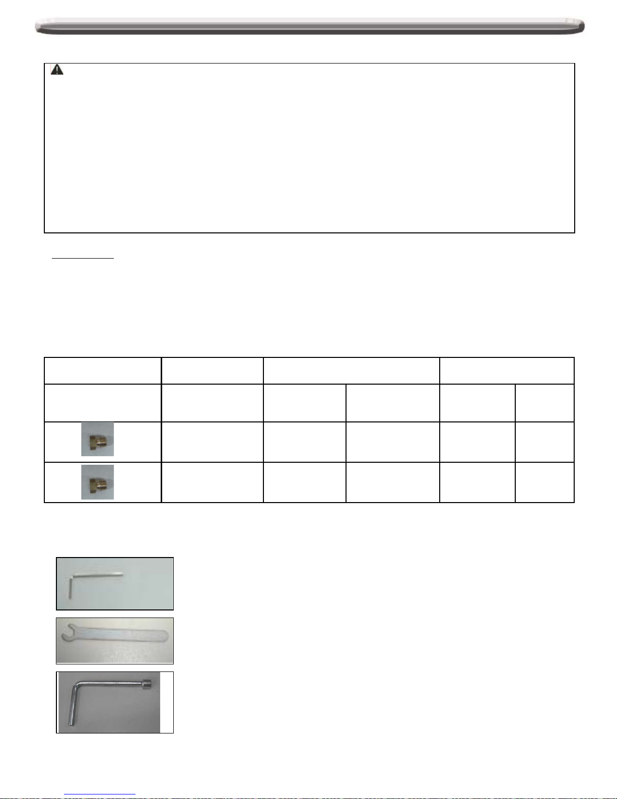
Orifice Chart
The different burner valves in this grill have different BTU ratings. This means that the amount of gas coming
from each orifice varies in order to create the BTU's. The holes in the orifices themselves are drilled to different
sizes so as to allow the proper amount of gas to flow through them. Please note the chart below as an easy
reference for the various orifice opening sizes for the different valves in the grill.
720-0830G, 730-0830Gorifice size
Liquid Propane (LP) Natural Gas (NG)
Components Orifice Size BTU
Orifice
Size BTU
Main Burner 1.02mm 12,000 1.70mm 12,000
Searing Side
Burner 1.15mm 15,000 1.90mm 15,000
Below tools are included in package:
Hex Key
6mm Nut Driver
6mm Wrench
24

Natural Gas Conversion for Model# 720-0830G
Main Tube Burner Conversion
Tools required:
Phillips Head Screwdriver (+)
6 mm Nut Driver
Steps:
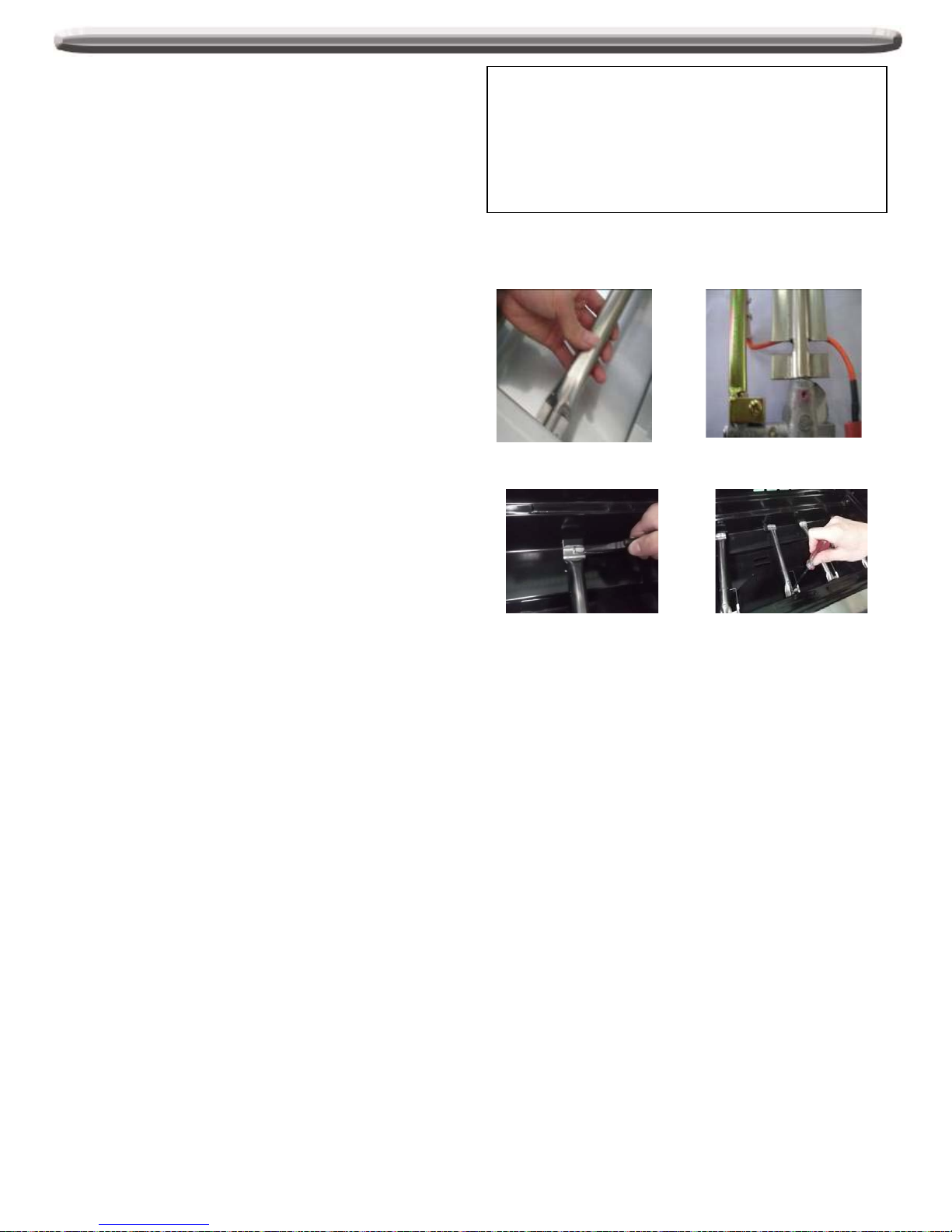
1. Remove the warming rack, cooking grids, and flame tamers.
2.
Remove the main tube burners by removing the pin securing the burners near the back wall of the firebox
and the screw near the front of the firebox that secures the igniter bracket to the burner. Gently lift the tube
burners up and out.
3. Remove LP (Liquid Propane) orifice with 6mm nut driver for each of the main burners, and replace with NG
orifice by hand (4 main burner).
4. Replace the tube burners and screw back into original position.
Nipper pliers
Phillips Head Screwdriver (—)
25
Natural Gas Conversion for Model# 720-0830G
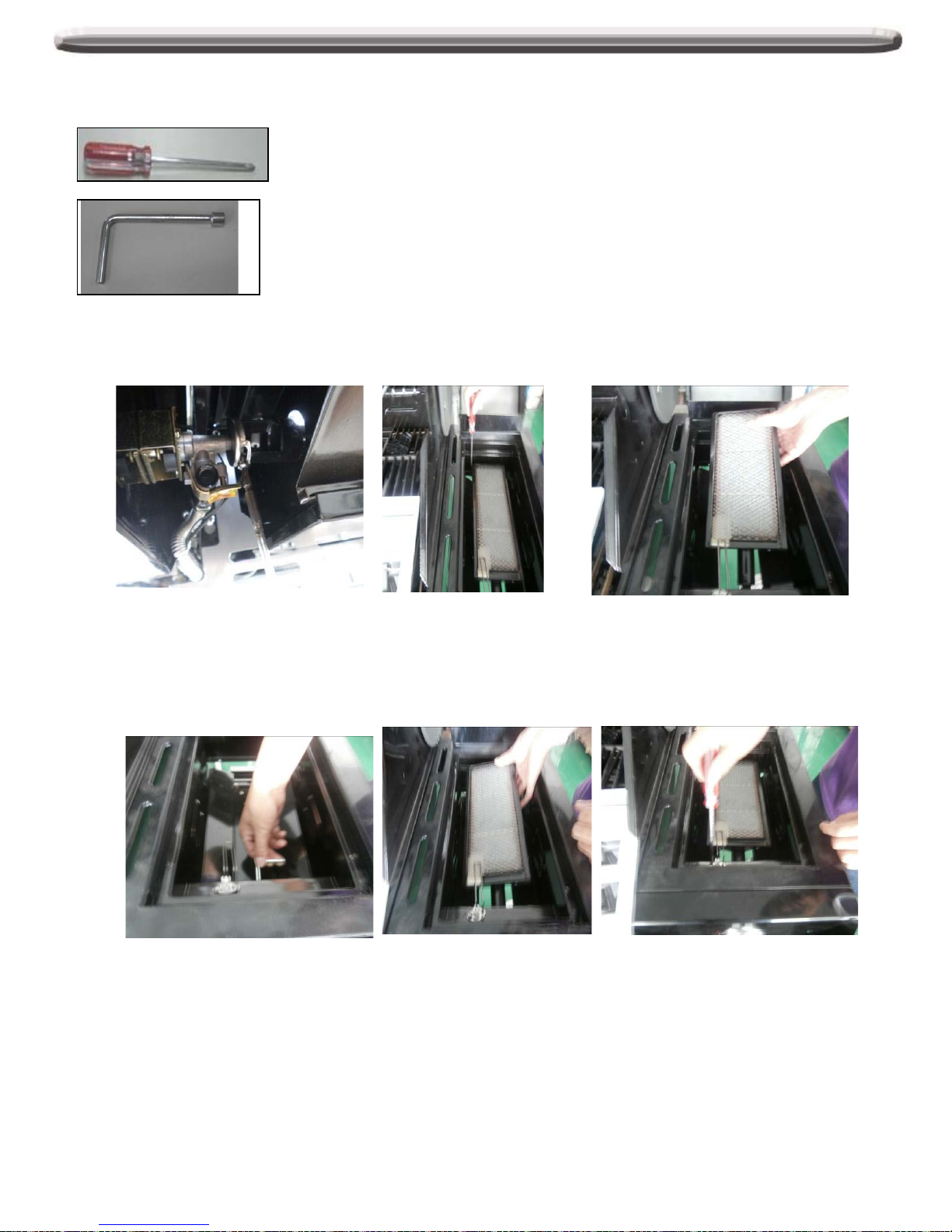
Searing Side Burner Conversion
Tools required:
Phillips Head Screwdriver (+)
6 mm Nut Driver
The step-by-step instruction for converting the searing side burne r’s orifice are stated below.
1.
Remove the screw under C bracket to take off the C bracket, then remove 2 screws at each corner of the
searing side burner and one screw for igniter.
2. Remove the searing side burner LP (Liquid Propane) orifice with 6mm driver, then Replace the NG
(Natural Gas) orifice to the connector by hand from beneath of side burner, then replace the side burner
to the original position, tighten screws for all corners.
26
Natural Gas Conversion for Model# 720-0830G
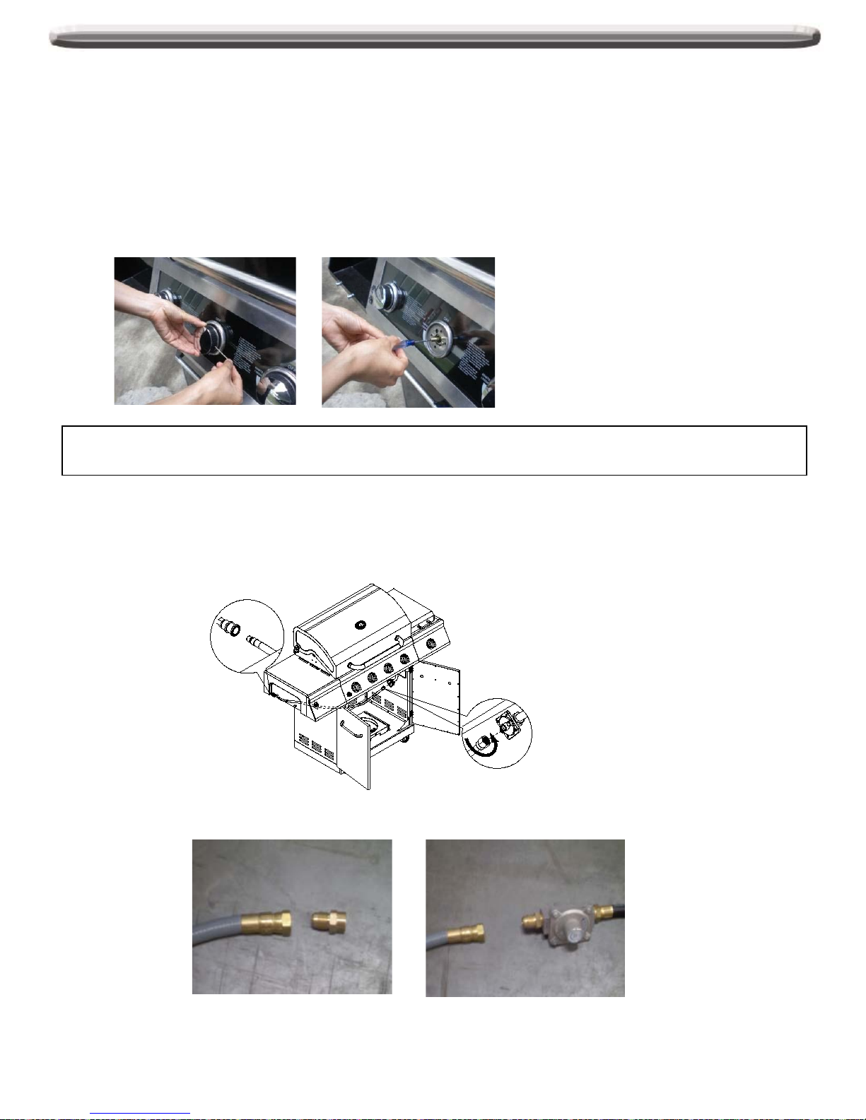
For Main Tube Burner Conversion Only
(The 3 steps below are not necessary for the Sear side burner )
You will need to adjust the High Flame setting screw when converting the barbecue from Propane to Natural Gas.
Please follow the steps as detailed below.
1. Remove each Control Knob of main tube burners by loosening the socket head grub screw with the hex
key.
2. Use a screwdriver to turn the High Flame Set Screw clockwise approximately 90 degree.
3. Check that burner operates at the new high flame setting - it may be necessary to adjust the screw setting
slightly to get the ideal burner flame height.
Warning!! Gas Valves are preset at the factory to operate on LP gas or NG gas. If you wish to convert, be sure to
consult your gas supplier or trained technician for the conversion.
A. After the Natural Gas regulator has been installed, attach the PVC gas hose to the regulator (See drawing
below).
B. Connect the other end of the PVC Gas Hose to the house gas line using the quick-connect fitting. To use
the quick connect fitting, lift the head of the connector back. Insert the end of the PVC hose and release the
head of the connector. Ensure connection is secure.
There is a brass adapter for natural gas lines that are pre-regulated. If the gas line is not pre-regulated, remove
the brass adapter and connect the regulator directly to the PVC gas hose.
Once conversion is completed, please attach the NG CSA certification sticker to the grill.
If you should have any questions rega r ding natural gas c onver sio n, ple as e c ontac t custome r ser vice at
1-888-301-0332.
27
 Loading...