

Page 1

324-Port EDR InfiniBand Switch-IB™
Series Switch Platform Hardware
User Manual
PN: CS7510
Rev 1.9
Mellanox Technologieswww.mellanox.com
Page 2

Doc #:MLNX-15-4748-324 2Mellanox Technologies
Page 3

Table of Contents
Revision History . . . . . . . . . . . . . . . . . . . . . . . . . . . . . . . . . . . . . . . . . . . . . . . 10
About this Manual . . . . . . . . . . . . . . . . . . . . . . . . . . . . . . . . . . . . . . . . . . . . . . . 11
Chapter 1 Overview . . . . . . . . . . . . . . . . . . . . . . . . . . . . . . . . . . . . . . . . . . . . 14
1.1 Product Information. . . . . . . . . . . . . . . . . . . . . . . . . . . . . . . . . . . . . . . . . . . 14
1.1.1 Serial Number and Product Version Information . . . . . . . . . . . . . . . . . . . . 14
1.1.2 Management Module MAC . . . . . . . . . . . . . . . . . . . . . . . . . . . . . . . . . . . . .
1.1.3 Product Physical Specifications and Power. . . . . . . . . . . . . . . . . . . . . . . . .
1.2 Features List . . . . . . . . . . . . . . . . . . . . . . . . . . . . . . . . . . . . . . . . . . . . . . . . . 17
1.3 InfiniBand EDR Overview . . . . . . . . . . . . . . . . . . . . . . . . . . . . . . . . . . . . . . .
1.4 Power Supply Redundancy . . . . . . . . . . . . . . . . . . . . . . . . . . . . . . . . . . . . .
1.4.1 AC Source Requirements . . . . . . . . . . . . . . . . . . . . . . . . . . . . . . . . . . . . . . . 17
1.4.2 Power Redundancy . . . . . . . . . . . . . . . . . . . . . . . . . . . . . . . . . . . . . . . . . . . .
1.5 Fan Redundancy . . . . . . . . . . . . . . . . . . . . . . . . . . . . . . . . . . . . . . . . . . . . . . 18
Chapter 2 Installation . . . . . . . . . . . . . . . . . . . . . . . . . . . . . . . . . . . . . . . . . . . 19
2.1 Installation Safety Warnings . . . . . . . . . . . . . . . . . . . . . . . . . . . . . . . . . . . . 19
2.2 Environmental and Safety Recommendations. . . . . . . . . . . . . . . . . . . . . .
2.3 Switch Components . . . . . . . . . . . . . . . . . . . . . . . . . . . . . . . . . . . . . . . . . . .
2.4 Unpacking the Switch System . . . . . . . . . . . . . . . . . . . . . . . . . . . . . . . . . . .
2.4.1 Verifying Crate Condition . . . . . . . . . . . . . . . . . . . . . . . . . . . . . . . . . . . . . . . 25
2.4.2 Opening the Chassis Crate . . . . . . . . . . . . . . . . . . . . . . . . . . . . . . . . . . . . . .
2.5 Physical Installation . . . . . . . . . . . . . . . . . . . . . . . . . . . . . . . . . . . . . . . . . . . 28
2.5.1 Installation Kit Parts . . . . . . . . . . . . . . . . . . . . . . . . . . . . . . . . . . . . . . . . . . . 29
2.5.2 Required Installation Tools. . . . . . . . . . . . . . . . . . . . . . . . . . . . . . . . . . . . . .
2.5.3 Installation Procedure. . . . . . . . . . . . . . . . . . . . . . . . . . . . . . . . . . . . . . . . . .
2.6 Ground Connections. . . . . . . . . . . . . . . . . . . . . . . . . . . . . . . . . . . . . . . . . . . 59
2.7 FRU Insertion and Extraction (Hot-Swappable) . . . . . . . . . . . . . . . . . . . . .
2.7.1 Power Supply Units . . . . . . . . . . . . . . . . . . . . . . . . . . . . . . . . . . . . . . . . . . . . 61
2.7.2 Leaf Modules . . . . . . . . . . . . . . . . . . . . . . . . . . . . . . . . . . . . . . . . . . . . . . . . .
2.7.3 Spine Modules . . . . . . . . . . . . . . . . . . . . . . . . . . . . . . . . . . . . . . . . . . . . . . . .
2.7.4 Fan Modules . . . . . . . . . . . . . . . . . . . . . . . . . . . . . . . . . . . . . . . . . . . . . . . . .
2.7.5 Management Module . . . . . . . . . . . . . . . . . . . . . . . . . . . . . . . . . . . . . . . . . .
2.8 InfiniBand QSFP Cable Installation . . . . . . . . . . . . . . . . . . . . . . . . . . . . . . . 74
2.9 Cable Holder Placement. . . . . . . . . . . . . . . . . . . . . . . . . . . . . . . . . . . . . . . .
2.9.1 Supported Approved Cables. . . . . . . . . . . . . . . . . . . . . . . . . . . . . . . . . . . . . 75
2.9.2 Cable Power Classes . . . . . . . . . . . . . . . . . . . . . . . . . . . . . . . . . . . . . . . . . . .
2.10 Power Connections. . . . . . . . . . . . . . . . . . . . . . . . . . . . . . . . . . . . . . . . . . . . 76
15
15
17
17
17
23
24
25
26
32
33
60
62
64
68
71
75
76
3Mellanox Technologies
Page 4

Chapter 3 Interfaces . . . . . . . . . . . . . . . . . . . . . . . . . . . . . . . . . . . . . . . . . . . . 77
3.1 LED Status Indicators . . . . . . . . . . . . . . . . . . . . . . . . . . . . . . . . . . . . . . . . . . 77
3.1.1 Power Supply Unit LEDs . . . . . . . . . . . . . . . . . . . . . . . . . . . . . . . . . . . . . . . . 77
3.1.2 System AC Power Interface . . . . . . . . . . . . . . . . . . . . . . . . . . . . . . . . . . . . .
3.1.3 Leaf Module LED Indicators . . . . . . . . . . . . . . . . . . . . . . . . . . . . . . . . . . . . .
3.1.4 Spine Module LED Indicators . . . . . . . . . . . . . . . . . . . . . . . . . . . . . . . . . . . .
3.1.5 Spine Side Panel Display LED Indicators . . . . . . . . . . . . . . . . . . . . . . . . . . .
3.1.6 Management Module LED Indicators . . . . . . . . . . . . . . . . . . . . . . . . . . . . .
3.1.7 Port Connector Interfaces . . . . . . . . . . . . . . . . . . . . . . . . . . . . . . . . . . . . . .
78
78
80
82
83
84
3.2 Air Flow . . . . . . . . . . . . . . . . . . . . . . . . . . . . . . . . . . . . . . . . . . . . . . . . . . . . . 85
3.3 QSFP Cable Power Budget Classification . . . . . . . . . . . . . . . . . . . . . . . . . .
3.4 Management Module Interfaces. . . . . . . . . . . . . . . . . . . . . . . . . . . . . . . . .
3.4.1 I2C/Console (RS232) . . . . . . . . . . . . . . . . . . . . . . . . . . . . . . . . . . . . . . . . . . . 85
3.4.2 Management . . . . . . . . . . . . . . . . . . . . . . . . . . . . . . . . . . . . . . . . . . . . . . . . .
3.4.3 USB . . . . . . . . . . . . . . . . . . . . . . . . . . . . . . . . . . . . . . . . . . . . . . . . . . . . . . . . .
3.4.4 Reset – RST . . . . . . . . . . . . . . . . . . . . . . . . . . . . . . . . . . . . . . . . . . . . . . . . . .
85
85
86
86
86
Chapter 4 Chassis Power Up . . . . . . . . . . . . . . . . . . . . . . . . . . . . . . . . . . . . . . 88
4.1 System Status After Power Up . . . . . . . . . . . . . . . . . . . . . . . . . . . . . . . . . . 88
4.2 Switch Shut-Down Procedure . . . . . . . . . . . . . . . . . . . . . . . . . . . . . . . . . . .
89
Chapter 5 Switch Management Tools . . . . . . . . . . . . . . . . . . . . . . . . . . . . . . 90
5.1 InfiniBand Subnet Manager . . . . . . . . . . . . . . . . . . . . . . . . . . . . . . . . . . . . . 91
5.2 Fabric Inspector (Diagnostics) . . . . . . . . . . . . . . . . . . . . . . . . . . . . . . . . . . .
5.3 Accessing the CPU via the Ethernet Connector . . . . . . . . . . . . . . . . . . . . .
5.4 Upgrading Software . . . . . . . . . . . . . . . . . . . . . . . . . . . . . . . . . . . . . . . . . . .
91
91
91
Chapter 6 Troubleshooting . . . . . . . . . . . . . . . . . . . . . . . . . . . . . . . . . . . . . . . 92
6.1 Power Supply Unit . . . . . . . . . . . . . . . . . . . . . . . . . . . . . . . . . . . . . . . . . . . . 92
6.2 Leaf Module . . . . . . . . . . . . . . . . . . . . . . . . . . . . . . . . . . . . . . . . . . . . . . . . .
6.3 Management Module. . . . . . . . . . . . . . . . . . . . . . . . . . . . . . . . . . . . . . . . . .
6.4 Spine Module . . . . . . . . . . . . . . . . . . . . . . . . . . . . . . . . . . . . . . . . . . . . . . . .
6.5 MLNX-OS® Software. . . . . . . . . . . . . . . . . . . . . . . . . . . . . . . . . . . . . . . . . . .
92
93
94
94
Appendix A Specification Data . . . . . . . . . . . . . . . . . . . . . . . . . . . . . . . . . . . 96
A.1 EMI Certification . . . . . . . . . . . . . . . . . . . . . . . . . . . . . . . . . . . . . . . . . . . 97
A.2 Approved Cables . . . . . . . . . . . . . . . . . . . . . . . . . . . . . . . . . . . . . . . . . . . 98
A.3 EMC Certifications . . . . . . . . . . . . . . . . . . . . . . . . . . . . . . . . . . . . . . . . . . 98
Appendix B Thermal Threshold Definitions . . . . . . . . . . . . . . . . . . . . . . . . . . 99
Appendix C Calculating the Weight of a Customized Chassis . . . . . . . . . . . 100
Appendix D Calculating the Power of a Chassis . . . . . . . . . . . . . . . . . . . . . . 101
Appendix E QSFP Interface . . . . . . . . . . . . . . . . . . . . . . . . . . . . . . . . . . . . . . 102
4Mellanox Technologies
Page 5

Appendix F MNG Console Interfaces . . . . . . . . . . . . . . . . . . . . . . . . . . . . . . 106
Appendix G Replacement Parts Ordering Numbers . . . . . . . . . . . . . . . . . . . 107
Appendix H Safety Warnings (Multiple Languages) . . . . . . . . . . . . . . . . . . . 108
H.1 Nordic Countries Notices . . . . . . . . . . . . . . . . . . . . . . . . . . . . . . . . . . . 108
H.2 Installation Safety Warnings (English) . . . . . . . . . . . . . . . . . . . . . . . . . 108
H.3 ( ( . . . . . . . . . . . . . . . . . . . . . . . . . . . . . 111
H.4 ⸘孬⸘⏷㊶巵⛙ (Chinese) . . . . . . . . . . . . . . . . . . . . . . . . . . . . . . . . . 114
H.5 Avertissements de sécurité pour l'installation (French). . . . . . . . . . . 118
H.6 Installation Sicherheitshinweise(German). . . . . . . . . . . . . . . . . . . . . . 121
H.7 Advertencias de seguridad de instalación (Spanish) . . . . . . . . . . . . . 124
H.8 Предупреждения по технике безопасности при установке (Russian) 127
H.9 Avertismente privind siguranţa la instalare (Romanian) . . . . . . . . . . 130
H.10 Sigurnosna upozorenja za instaliranje (Croatian) . . . . . . . . . . . . . . . . 134
H.11 Avvertenze di sicurezza per l’installazione (italiano) . . . . . . . . . . . . . 137
H.12 Montaj Güvenlik Uyarıları (Türkçe) . . . . . . . . . . . . . . . . . . . . . . . . . . . 141
H.13 Japan VCCI Class A Statement . . . . . . . . . . . . . . . . . . . . . . . . . . . . . . . 144
H.14 ۶߇ࢷˁˈଞ˲߭
5Mellanox Technologies
Page 6

List of Tables
Table 1: User Manual Revision History. . . . . . . . . . . . . . . . . . . . . . . . . . . . . . . . . . . . . . . . . .10
Table 2: Reference Documents and Websites . . . . . . . . . . . . . . . . . . . . . . . . . . . . . . . . . . . .11
Table 3: Mellanox Part Number Legend. . . . . . . . . . . . . . . . . . . . . . . . . . . . . . . . . . . . . . . . . 12
Table 4: Power Supply OPN . . . . . . . . . . . . . . . . . . . . . . . . . . . . . . . . . . . . . . . . . . . . . . . . . . .18
Table 5: Chassis Installation Kit Items. . . . . . . . . . . . . . . . . . . . . . . . . . . . . . . . . . . . . . . . . . . 29
Table 6: Cable Management Installation Kit Parts. . . . . . . . . . . . . . . . . . . . . . . . . . . . . . . . .31
Table 7: Leaf Status LED. . . . . . . . . . . . . . . . . . . . . . . . . . . . . . . . . . . . . . . . . . . . . . . . . . . . . . 78
Table 8: Bad Port LED Configurations . . . . . . . . . . . . . . . . . . . . . . . . . . . . . . . . . . . . . . . . . . .79
Table 9: Connector Physical and Logical Link Indications . . . . . . . . . . . . . . . . . . . . . . . . . . .79
Table 10: Spine Status LED. . . . . . . . . . . . . . . . . . . . . . . . . . . . . . . . . . . . . . . . . . . . . . . . . . . . . 80
Table 11: Spine Fan Status LED . . . . . . . . . . . . . . . . . . . . . . . . . . . . . . . . . . . . . . . . . . . . . . . . . 81
Table 12: Spine to Leaf IB Link Status . . . . . . . . . . . . . . . . . . . . . . . . . . . . . . . . . . . . . . . . . . . .81
Table 13: Bad Port LED Configurations . . . . . . . . . . . . . . . . . . . . . . . . . . . . . . . . . . . . . . . . . . .81
Table 14: Spine-Side Panel LED Display for Normal Operation . . . . . . . . . . . . . . . . . . . . . . . 82
Table 15: Management LED Display for Normal Operation . . . . . . . . . . . . . . . . . . . . . . . . . .84
Table 16: Switch Specification CS7510 . . . . . . . . . . . . . . . . . . . . . . . . . . . . . . . . . . . . . . . . . . .96
Table 17: Switch System Weight Calculation . . . . . . . . . . . . . . . . . . . . . . . . . . . . . . . . . . . . .100
Table 18: Power Consumption of Chassis Parts. . . . . . . . . . . . . . . . . . . . . . . . . . . . . . . . . . .101
Table 19: QSFP Cable Power Consumption . . . . . . . . . . . . . . . . . . . . . . . . . . . . . . . . . . . . . .101
Table 20: Calculating Total Switch System Power Consumption . . . . . . . . . . . . . . . . . . . . .101
Table 21: InfiniBand QSFP Connector Pin-out . . . . . . . . . . . . . . . . . . . . . . . . . . . . . . . . . . . .102
Table 22: RJ-45 CONSOLE and I²C Pinout . . . . . . . . . . . . . . . . . . . . . . . . . . . . . . . . . . . . . . . .106
Table 23: Replacement Parts Ordering Numbers . . . . . . . . . . . . . . . . . . . . . . . . . . . . . . . . .107
6Mellanox Technologies
Page 7

List of Figures
Figure 1: Product Label . . . . . . . . . . . . . . . . . . . . . . . . . . . . . . . . . . . . . . . . . . . . . . . . . . . . . . . . . . .14
Figure 2: Product Label Tab Location . . . . . . . . . . . . . . . . . . . . . . . . . . . . . . . . . . . . . . . . . . . . . . . . .15
Figure 3: Management Module MAC Address Location . . . . . . . . . . . . . . . . . . . . . . . . . . . . . . . . . .
Figure 4: CS7510 . . . . . . . . . . . . . . . . . . . . . . . . . . . . . . . . . . . . . . . . . . . . . . . . . . . . . . . . . . . . . . . . . .
Figure 5: Shock Stickers . . . . . . . . . . . . . . . . . . . . . . . . . . . . . . . . . . . . . . . . . . . . . . . . . . . . . . . . . . . .
Figure 6: Crate Screws . . . . . . . . . . . . . . . . . . . . . . . . . . . . . . . . . . . . . . . . . . . . . . . . . . . . . . . . . . . . .
Figure 7: Distance Between the Vertical Supports . . . . . . . . . . . . . . . . . . . . . . . . . . . . . . . . . . . . . . .
Figure 8: Chassis Installation Kit . . . . . . . . . . . . . . . . . . . . . . . . . . . . . . . . . . . . . . . . . . . . . . . . . . . . . .
Figure 9: Cable Management Installation . . . . . . . . . . . . . . . . . . . . . . . . . . . . . . . . . . . . . . . . . . . . . .
Figure 10: Shelf Installation Kit . . . . . . . . . . . . . . . . . . . . . . . . . . . . . . . . . . . . . . . . . . . . . . . . . . . . . . . .
Figure 11: Tools for Installation . . . . . . . . . . . . . . . . . . . . . . . . . . . . . . . . . . . . . . . . . . . . . . . . . . . . . . .
Figure 12: Cage Nut Placement for Shelf on BEAM-1 and BEAM-2 . . . . . . . . . . . . . . . . . . . . . . . . . . .
Figure 13: Cage Nut Placement for Shelf on BEAM-3 and BEAM-4 . . . . . . . . . . . . . . . . . . . . . . . . . . .
Figure 14: Cage Nut Placement for Support Bracket . . . . . . . . . . . . . . . . . . . . . . . . . . . . . . . . . . . . . .
Figure 15: Cage Nut Placement for Switch System Chassis on Spine Side . . . . . . . . . . . . . . . . . . . . .
Figure 16: Cage Nut Placement for Cable Holders on Leaf Side . . . . . . . . . . . . . . . . . . . . . . . . . . . . .
Figure 17: Loosening the Leaf-Side Shelf Arms . . . . . . . . . . . . . . . . . . . . . . . . . . . . . . . . . . . . . . . . . . .
Figure 18: Adjusting the Leaf-Side Shelf Arms . . . . . . . . . . . . . . . . . . . . . . . . . . . . . . . . . . . . . . . . . . .
Figure 19: Placing Shelf . . . . . . . . . . . . . . . . . . . . . . . . . . . . . . . . . . . . . . . . . . . . . . . . . . . . . . . . . . . . .
Figure 20: Tightening Shelf Cage Nut Screws on Spine Side . . . . . . . . . . . . . . . . . . . . . . . . . . . . . . . .
Figure 21: Tightening Shelf Cage Nut Screws on Leaf Side . . . . . . . . . . . . . . . . . . . . . . . . . . . . . . . . .
Figure 22: Tightening Spine-side Shelf Arm Screws . . . . . . . . . . . . . . . . . . . . . . . . . . . . . . . . . . . . . . .
Figure 23: Screwing Leaf-side Fasteners . . . . . . . . . . . . . . . . . . . . . . . . . . . . . . . . . . . . . . . . . . . . . . . .
Figure 24: Tightening Spine-side Shelf Arm Screws . . . . . . . . . . . . . . . . . . . . . . . . . . . . . . . . . . . . . . .
Figure 25: Tightening Leaf-side Shelf Screws . . . . . . . . . . . . . . . . . . . . . . . . . . . . . . . . . . . . . . . . . . . .
Figure 26: Weld Bracket Assembly . . . . . . . . . . . . . . . . . . . . . . . . . . . . . . . . . . . . . . . . . . . . . . . . . . . . .4
Figure 27: Placement of Chassis in Rack – Top View . . . . . . . . . . . . . . . . . . . . . . . . . . . . . . . . . . . . . .
Figure 28: Fork Lift . . . . . . . . . . . . . . . . . . . . . . . . . . . . . . . . . . . . . . . . . . . . . . . . . . . . . . . . . . . . . . . . . .
Figure 29: Mechanical Lift . . . . . . . . . . . . . . . . . . . . . . . . . . . . . . . . . . . . . . . . . . . . . . . . . . . . . . . . . . . .
Figure 30: Rack and Chassis Alignment . . . . . . . . . . . . . . . . . . . . . . . . . . . . . . . . . . . . . . . . . . . . . . . . .
Figure 31: Rotated Strip and Bracket Weld . . . . . . . . . . . . . . . . . . . . . . . . . . . . . . . . . . . . . . . . . . . . . .
Figure 32: Sliding Chassis in Rack . . . . . . . . . . . . . . . . . . . . . . . . . . . . . . . . . . . . . . . . . . . . . . . . . . . . . .
Figure 33: Sliding in Chassis Slides . . . . . . . . . . . . . . . . . . . . . . . . . . . . . . . . . . . . . . . . . . . . . . . . . . . . .
Figure 34: Sliding Chassis into Rack . . . . . . . . . . . . . . . . . . . . . . . . . . . . . . . . . . . . . . . . . . . . . . . . . . . .
15
16
26
27
28
30
31
32
32
33
34
35
36
37
38
39
40
41
41
42
42
43
44
46
46
47
47
48
49
50
51
5
7Mellanox Technologies
Page 8

Figure 35: Screwing the Chassis to the Rack . . . . . . . . . . . . . . . . . . . . . . . . . . . . . . . . . . . . . . . . . . . .52
Figure 36: Screwing the 4-Oval Washer Plates . . . . . . . . . . . . . . . . . . . . . . . . . . . . . . . . . . . . . . . . . . .
Figure 37: Removing the Weld Bracket . . . . . . . . . . . . . . . . . . . . . . . . . . . . . . . . . . . . . . . . . . . . . . . . .
Figure 38: Leaf Side Fixing Bracket With Chassis . . . . . . . . . . . . . . . . . . . . . . . . . . . . . . . . . . . . . . . . .
Figure 39: Spine Side Fixing Bracket With Chassis . . . . . . . . . . . . . . . . . . . . . . . . . . . . . . . . . . . . . . . .
Figure 40: Leaf Side Fixing Bracket With Shelf . . . . . . . . . . . . . . . . . . . . . . . . . . . . . . . . . . . . . . . . . . .
Figure 41: Spine Side Fixing Bracket With Shelf . . . . . . . . . . . . . . . . . . . . . . . . . . . . . . . . . . . . . . . . . .
Figure 42: Installing Cable Holders . . . . . . . . . . . . . . . . . . . . . . . . . . . . . . . . . . . . . . . . . . . . . . . . . . . . .
Figure 43: Grounding Posts . . . . . . . . . . . . . . . . . . . . . . . . . . . . . . . . . . . . . . . . . . . . . . . . . . . . . . . . . .
Figure 44: Power Unit AC Inlet Numbering . . . . . . . . . . . . . . . . . . . . . . . . . . . . . . . . . . . . . . . . . . . . . .
Figure 45: Power Supply Unit . . . . . . . . . . . . . . . . . . . . . . . . . . . . . . . . . . . . . . . . . . . . . . . . . . . . . . . . .
Figure 46: Releasing Leaf Ejector Handles . . . . . . . . . . . . . . . . . . . . . . . . . . . . . . . . . . . . . . . . . . . . . . .
Figure 47: Intact Leaf Signal Connectors . . . . . . . . . . . . . . . . . . . . . . . . . . . . . . . . . . . . . . . . . . . . . . . .
Figure 48: Intact Leaf Power Pins . . . . . . . . . . . . . . . . . . . . . . . . . . . . . . . . . . . . . . . . . . . . . . . . . . . . . .
Figure 49: Leaf Module Insertion . . . . . . . . . . . . . . . . . . . . . . . . . . . . . . . . . . . . . . . . . . . . . . . . . . . . . .
Figure 50: Management Module Numbering . . . . . . . . . . . . . . . . . . . . . . . . . . . . . . . . . . . . . . . . . . . .
Figure 51: Releasing Spine Ejector Handles . . . . . . . . . . . . . . . . . . . . . . . . . . . . . . . . . . . . . . . . . . . . .
Figure 52: Intact Spine Signal Connectors . . . . . . . . . . . . . . . . . . . . . . . . . . . . . . . . . . . . . . . . . . . . . . .
Figure 53: Intact Spine Power Pin Holders . . . . . . . . . . . . . . . . . . . . . . . . . . . . . . . . . . . . . . . . . . . . . .
Figure 54: Spine Module Insertion . . . . . . . . . . . . . . . . . . . . . . . . . . . . . . . . . . . . . . . . . . . . . . . . . . . . .
Figure 55: Leaf Fan Locations on the Chassis . . . . . . . . . . . . . . . . . . . . . . . . . . . . . . . . . . . . . . . . . . . .
Figure 56: Leaf Fan Module Extraction . . . . . . . . . . . . . . . . . . . . . . . . . . . . . . . . . . . . . . . . . . . . . . . . .
Figure 57: Spine Fan Modules . . . . . . . . . . . . . . . . . . . . . . . . . . . . . . . . . . . . . . . . . . . . . . . . . . . . . . . .
Figure 58: Fan Status LED on the Spine Module . . . . . . . . . . . . . . . . . . . . . . . . . . . . . . . . . . . . . . . . . .
Figure 59: Releasing Management Ejector Handles . . . . . . . . . . . . . . . . . . . . . . . . . . . . . . . . . . . . . . .
Figure 60: Intact Signal Connectors . . . . . . . . . . . . . . . . . . . . . . . . . . . . . . . . . . . . . . . . . . . . . . . . . . . .
Figure 61: Intact Management Power Pins . . . . . . . . . . . . . . . . . . . . . . . . . . . . . . . . . . . . . . . . . . . . . .
Figure 62: Management Module Insertion . . . . . . . . . . . . . . . . . . . . . . . . . . . . . . . . . . . . . . . . . . . . . .
Figure 63: Cable Supporter Placement . . . . . . . . . . . . . . . . . . . . . . . . . . . . . . . . . . . . . . . . . . . . . . . . .
Figure 64: AC Inlets . . . . . . . . . . . . . . . . . . . . . . . . . . . . . . . . . . . . . . . . . . . . . . . . . . . . . . . . . . . . . . . . .
Figure 65: Power Supply Unit Status Indications . . . . . . . . . . . . . . . . . . . . . . . . . . . . . . . . . . . . . . . . .
Figure 66: CS7510 PSU Cover . . . . . . . . . . . . . . . . . . . . . . . . . . . . . . . . . . . . . . . . . . . . . . . . . . . . . . . .
Figure 67: Leaf Module LED Indicators . . . . . . . . . . . . . . . . . . . . . . . . . . . . . . . . . . . . . . . . . . . . . . . . .
Figure 68: Spine Status LEDs . . . . . . . . . . . . . . . . . . . . . . . . . . . . . . . . . . . . . . . . . . . . . . . . . . . . . . . . . .
Figure 69: Spine Side Panel Display Status Indications . . . . . . . . . . . . . . . . . . . . . . . . . . . . . . . . . . . .
Figure 70: Management Module Indications . . . . . . . . . . . . . . . . . . . . . . . . . . . . . . . . . . . . . . . . . . . .
53
54
55
56
57
58
59
60
61
61
62
63
63
64
65
66
67
67
68
69
69
70
70
72
72
73
73
75
76
77
78
78
80
82
83
8Mellanox Technologies
Page 9

Figure 71: Port Numbering . . . . . . . . . . . . . . . . . . . . . . . . . . . . . . . . . . . . . . . . . . . . . . . . . . . . . . . . . . .84
Figure 72: Top and Bottom Ports . . . . . . . . . . . . . . . . . . . . . . . . . . . . . . . . . . . . . . . . . . . . . . . . . . . . . .
Figure 73: Management Module Interfaces . . . . . . . . . . . . . . . . . . . . . . . . . . . . . . . . . . . . . . . . . . . . .
Figure 74: Spine Side Panel Display Status Indications . . . . . . . . . . . . . . . . . . . . . . . . . . . . . . . . . . . .
Figure 75: Management Module Status Indications for Normal Operation (Master)
Figure 76: Management Module Status Indications for Normal Operation (Slave)
. . . . . . . . . . . .89
. . . . . . . . . . . . .89
Figure 77: InfiniBand QSFP Connector Symbol . . . . . . . . . . . . . . . . . . . . . . . . . . . . . . . . . . . . . . . . . .
Figure 78: QSFP Connector Male and Female Views . . . . . . . . . . . . . . . . . . . . . . . . . . . . . . . . . . . . .
Figure 79: RJ45 to DB9 Harness Pinout . . . . . . . . . . . . . . . . . . . . . . . . . . . . . . . . . . . . . . . . . . . . . . . .
85
85
89
104
105
106
9Mellanox Technologies
Page 10

Revision History
Table 1 - User Manual Revision History
Rev Date Description
1.9 14 August, 2017 Updated:
1.8 5 March, 2017 Added:
1.7 8 February, 2017 Updated:
1.6 1 December, 2016 Updated:
1.5 17 August, 2016 Updated:
1.4 29 June, 2016 Added Section 1.5, “Fan Redundancy,” on page 18
Note to Chapter 2.7.2, “Leaf Modules”
Note to Chapter 2.7.3, “Spine Modules”
Appendix F, “MNG Console Interfaces,” on page 106
Note to Appendix 3.4.1, “I2C/Console (RS232),” on page 85
Korean warning notes
• “Extracting Spine Module #1 or #2” on page 63
• Section 3.1.1, “Power Supply Unit LEDs,” on page 77
• Replacement kit part number “MTDF-KIT-B”
1.3 18 May, 2016 Added:
• Section 2.5.2, “Required Installation Tools,” on page 31
Updated:
• Table 5, “Chassis Installation Kit Items,” on page 28
• Section 2.5.3, “Installation Procedure,” on page 32
• Section 3.4.4, “Reset – RST,” on page 86
1.2 1 May, 2016 Updated:
• Document title
• Section “About this Manual,” on page 11
• Chapter 1, “Overview,” on page 14
• Appendix G, “Replacement Parts Ordering Numbers,” on page 107 with
Switch-IB 2 replacement leaf and spine
1.1 20 March, 2016 Updated:
• Note in Section 4.1, “System Status After Power Up,” on page 88
• Section 6.1, “Power Supply Unit,” on page 92 step 7
• “Regulatory Compliance” in Table 16, “Switch Specification CS7510,”
on page 96
1.0 19 December
2015
First release
10Mellanox Technologies
Page 11

About this Manual
This manual provides an overview of the Switch-IB™/Switch-IB™ 2 series based InfiniBand
CS7510 director switch and guidelines for its operation.
Intended Audience
This manual is intended for users and system administrators responsible for installing and setting
up the chassis platform.
®
The manual assumes familiarity with the InfiniBand
Related Documentation
The documentation set accompanying the QSFP28 Chassis InfiniBand Switch platform includes
the following:
Table 2 - Reference Documents and Websites
Document Name Description
architecture specification.
InfiniBand Architecture Specification, Vol. 1, Release 1.2.1
Switch Product Release Notes For possible hardware issues see the switch support prod-
MLNX-OS® User Manual for VPI This document contains information regarding configur-
Dismantling Procedures Dismantling user guides for Mellanox Technologies prod-
The InfiniBand Architecture Specification that is provided by IBTA
uct page. This requires a customer support login. Look up
the relevant Switch-IB™ based switch system/series
release note file.
ing and managing Mellanox Technologies SwitchX®
switch platforms listing all of the commands available
through MLNX-OS with explanations and examples.
ucts organized by product category.
http://www.mellanox.com/page/dismantling_procedures
Conventions
Throughout this manual, the name CS7510 and the terms chassis and switch are used to describe
the port QSFP28 InfiniBand chassis, unless explicitly indicated otherwise.
The following icons are used throughout this document to indicate information
to the user.
that is important
This symbol indicates information that is helpful to the user.
11Mellanox Technologies
Page 12
This symbol indicates a situation that can potentially cause damage to hardware or software.
This symbol makes recommendations to the user.
Mellanox Part Numbering Legend
Table 3 - Mellanox Part Number Legend
Place Field Decoder
A Company name M – Mellanox Technologies
BB Switch system type CS – Chassis
MB – Management Board
SB – Switch-IB™ in leaf or spine
module
C Data rate 7 – EDR InfiniBand
D System type 5 – director switch
EE Number of ports 00 – 648 ports
10 – 324 ports
20 – 216 ports
12Mellanox Technologies
Page 13
1 Overview
This chapter provides an overview of the CS7510 QSFP28 InfiniBand director switch platform
(referenced in this document as “the chassis” or “the switch”) and its operational environment.
The Mellanox CS7510 switch system provides the highest performing fabric solution by delivering high bandwidth and low latency to enterprise data centers (EDC), high-performance comput
ing (HPC) and embedded environments. Networks built with the CS7510 system
converged traffic with the combination of assured bandwidth and granular quality of service.
Built with Mellanox’s 6th and 7th generation of Switch-IB™ and Switch-IB™ 2 switch devices,
CS7510 systems provide up to 100Gb/s full bidirectional bandwidth per port. With up to 324
ports in a 16U rack space, this system is among the densest switching systems available.
The switch platform comes pre-installed with all necessary firmware
within an InfiniBand fabric and requires an InfiniBand compliant Subnet Manager running from
one of the hosts or the management module of the switch system. The initial configuration procedure should be followed to initialize the switch before connecting
normal operation can proceed. (See the installation guide for details regarding the initial configuration.) Once connected to the network, the Subnet Management software automatically
ers and configures the fabric and begins utilizing the switch.
The Mellanox Operating System (MLNX-OS®) software package provides a
and network management tools as well as connectivity software for servers and storage, and is
available on the Mellanox website.
Basic installation is covered in Chapter 2, “Installation” on page 18.
can carry
standard operation
for
it
to the network after which
discov-
subnet manager
Overview
-
Hot-swapping components and hardware maintenance is covered in Section 2.7, “FRU Insertion
and Extraction (Hot-Swappable),” on page 54.
1.1 Product Information
1.1.1 Serial Number and Product Version Information
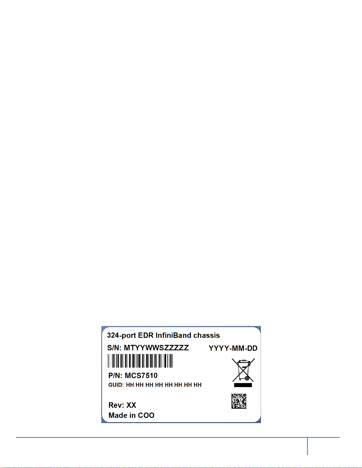
The serial number, GUID identifier and product version information are found on the label
attached to the pull-out tab below the Mellanox logo on the spine side of the chassis.
Figure 1: Product Label
14Mellanox Technologies
Page 14
The GUID is the System Image GUID according to the IB spec. It is burned on the board which
is in the chassis. All the boards and the management software look for this GUID in addition to
their own Node GUID.
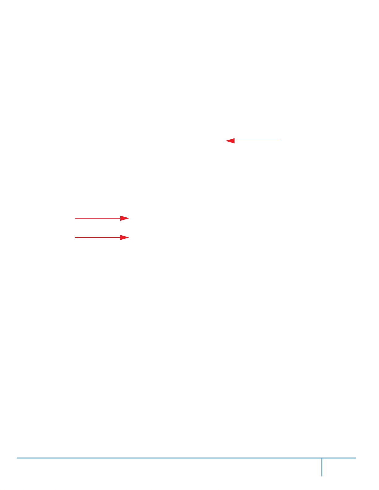
Figure 2: Product Label Tab Location
1.1.2 Management Module MAC
Each management module has a label with its MAC address. See Figure 3 for the location of this
label.
Figure 3: Management Module MAC Address Location
Overview
The product
label tab is
located here on
the spine side
1.1.3 Product Physical Specifications and Power
The switch itself is 16U tall but requires an extra 1U to install the shelf.
The switch ships in a minimum base configuration plus additional modules
chosen customer configuration. Optional modules included:
• Management modules
• Spine modules
•
Leaf modules
depending on the
15Mellanox Technologies
Page 15
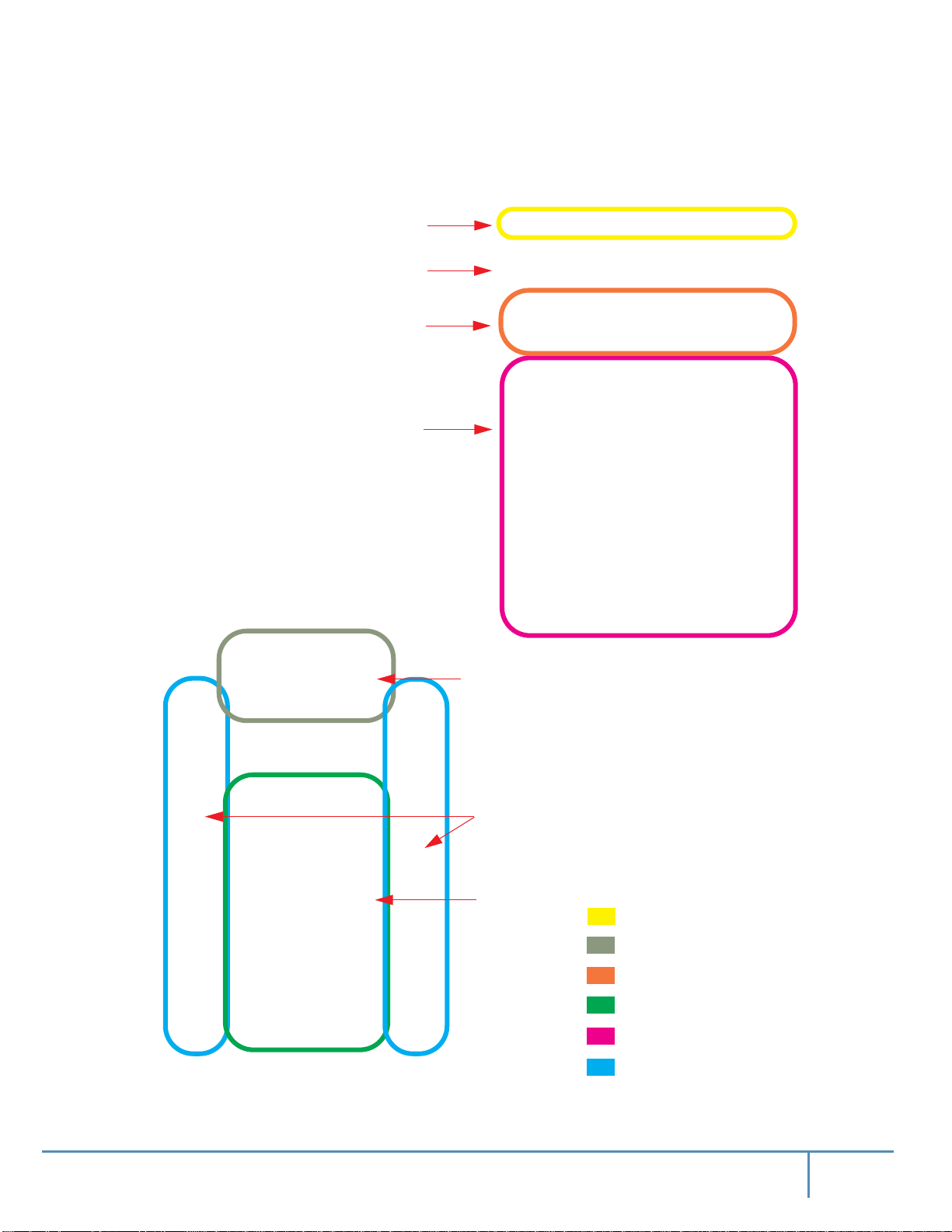
The following figure presents a fully populated leaf and spine side.
Figure 4: CS7510
AC inlets
Fuse box
(Do not tamper with)
Management Modules
Leafs
Each leaf has 36 ports and up to 9
leafs can fit in the chassis
Overview
Power supplies
Chassis fan modules
Spines
AC inlets: 6
Power supply units: 6
Management modules: 2
Spine modules: 9
Leaf modules: 9
Chassis fan modules: 12
16Mellanox Technologies
Page 16

1.2 Features List
• 324 EDR (100Gb/s) InfiniBand ports in a 16U switch
• 65 Tb/s aggregate data switching capacity with ultra low latency
• IBTA 1.3 and 1.2.1 compliant
• Up to EDR link speeds
• N+N power supply
• Chassis high availability
• sMB high availability
1.3 InfiniBand EDR Overview
The Mellanox CS7510 switch system supports EDR, standard InfiniBand data rate, where each
lane of a 4X port runs a bit rate of 25.78125Gb/s. The EDR physical layer is an IBTA specified
physical layer using different block types, deskew mechanism and framing rules.
Both FDR and EDR support Forward Error Correction (FEC), as described in
2007 (Amendment to IEEE Std 802.3-2005) chapter 74.
Overview
IEEE Std 802.3ap-
EDR is only guaranteed to work with approved Mellanox cables.
1.4 Power Supply Redundancy
The CS7510 platform comes standard with 6 power supplies. Each power supply is capable to
provide 48V
1.4.1 AC Source Requirements
CS7510 system supports 220VAC operation only. No support for 110VAC source. Each AC source
should be capable of providing at least 12A input current.
1.4.2 Power Redundancy
The minimum complement of PSUs which allows the chassis to run at full capacity is 3. The following two redundancy options are available:
• No redundancy (combined mode)
• N+N configuration (grid-redundant mode)
2500W output power.
DC
N+N redundancy only works with a supply voltage of 220V.
17Mellanox Technologies
Page 17
The chassis PSUs are fed from two power grids for high availability. The second power grid
can be supplied by any of the following:
• a backup power supply grid
• a generator
• a battery backup system
• any combination of the above
Overview
Connecting 3 power supplies to one power supply grid and the remaining
secondary power supply grid will create N+N redundancy. This is high availability. Under
these conditions should a power grid fail (an electric company power failure or blackout for
example) power grid High Availability will continue to keep the chassis running at full capacity
through the secondary or backup power supply grid.
The system cannot run with less than 3 PSUs, thus if one of the power grids is down
there is no power or PSU redundancy in the system.
When the power drops below the required minimum due to power supply failure, MLNX-OS®
may power down some leafs. If this happens it may be necessary to reboot the chassis once the
defective PSU has been replaced. Two ways to reboot are to use the reboot command in the CLI
or reboot through the WebUI.
Table 4 - Power Supply OPN
PSU OPN Wattage Description
MTDF-PS-A 2500W Supplies N+N redundancy for all switch chassis at 220 Volts
1.5 Fan Redundancy
3
power supplies to a
Whether it is a chassis, or a spine fan unit, Mellanox’s EDR director switch chassis supports single fan failure without performance degradation.
When a fan unit fails, it must remain in the chassis until a replacement is available. At that point,
the
failed fan unit must be promptly replaced so that the chassis remains with an empty slot for as
little time as possible.
18Mellanox Technologies
Page 18

2 Installation
This chassis can be installed in standard 19” racks that have depths between 715850mm between the vertical supports of the rack.
Installation and initialization of the chassis is a simple process requiring attention to the normal
mechanical, power, and thermal precautions for rack-mounted equipment. The chassis comes
only with the power supplies and fans pre-installed. The rest of the openings are populated with
blanks. All of the leafs, spines, and management modules are shipped in a separate package.
The chassis requires initial configuration to get the chassis and
ning through remote management.
This unit is intended for installation in a restricted access location. A restricted access
area can be accessed only through the use of a special tool, lock and key, or other
means of security.
2.1 Installation Safety Warnings
management up and run-
fabric
Installation
These safety warnings are in English. For other languages, please refer to the appendixes.
1. Installation Instructions
Read all installation instructions before connecting the equipment to the power source.
2. Bodily Injury Due to Weight
Use enough people to safely lift this product.
3. Heavy Equipment
This equipment is very heavy and should be moved using a mechanical lift to avoid
injuries.
19Mellanox Technologies
Page 19
4. Installation in Restricted Access Location
This unit is intended for installation in a Restricted Access Location.
5. Risk of Electric Shock
Risk of Electric Shock!
With the fan module removed power pins are accessible within the module cavity.
DO NOT insert tools or body parts into the fan module cavity.
6. Over-temperature
This equipment should not be operated in an area with an ambient temperature exceeding the maximum recommended: 40°C (104°F). Moreover, to guarantee proper air
flow, allow at least 8cm (3 inches) of clearance around the ventilation openings.
7. Stacking the Chassis
The chassis should not be stacked on any other equipment. If the chassis falls, it can
cause bodily injury and equipment damage.
Installation
8. Redundant Power Supply Connection – Electrical Hazard
This product includes a redundant power or a blank in its place. In case of a blank
power supply, do not operate the product with the blank cover removed or not securely
fastened.
9. Double Pole/Neutral Fusing
This system has double pole/neutral fusing. Remove all power cords before opening
the cover of this product or touching any internal parts.
10.Multiple Power Inlets
Risk of electric shock and energy hazard.
The PSUs are all independent.
Disconnect all power supplies to ensure a powered down state inside of the switch
platform.
11.During Lightning – Electrical Hazard
During periods of lightning activity, do not work on the equipment or connect or disconnect cables.
20Mellanox Technologies
Page 20

12.Copper InfiniBand Cable Connecting/Disconnecting
Copper InfiniBand cables are heavy and not flexible, as such they should be carefully
attached to or detached from the connectors. Refer to the cable manufacturer for special warnings/instructions.
13.Rack Mounting and Servicing
When this product is mounted or serviced in a rack, special precautions must be taken
to ensure that the system remains stable. In general you should fill the rack with equipment starting from the bottom to the top.
14.Equipment Installation
This equipment should be installed, replaced, and/or serviced only by trained and qualified personnel.
15.Equipment Disposal
Disposal of this equipment should be in accordance to all national laws and regulations.
Installation
16.Local and National Electrical Codes
This equipment should be installed in compliance with local and national electrical
codes.
17. Installation Codes
This device must be installed according to the latest version of the country national
electrical codes. For North America, equipment must be installed in accordance to the
applicable requirements in the US National Electrical Code and the Canadian Electrical Code.
18.Battery Replacement
Warning: Replace only with UL Recognized battery, certified for maximum abnormal
charging current not less than 4mA
There is a risk of explosion should the battery be replaced with a battery of an incorrect
type.
Dispose of used batteries according to the instructions.
21Mellanox Technologies
Page 21
19.UL Listed and CSA Certified Power Supply Cord
For North American power connection, select a power supply cord that is UL Listed
and CSA Certified, 3 - conductor, [16 AWG], terminated with a molded plug rated at
125 V, [13 A], with a minimum length of 1.5m [six feet] but no longer than 4.5m.
For European connection, select a power supply cord that is internationally
harmonized and marked “<HAR>”, 3 - conductor, minimum 1.0 mm2 wire, rated at
300 V, with a PVC insulated jacket. The cord must have a molded plug rated at 250 V,
10 A.
20.High Leakage Current
Warning: High leakage current; Earth connection essential before connecting supply.
21.Add GND connection information
Before connecting this device to the power line, the protective earth terminal screws of
this device must be connected to the protective earth in the building installation.
(GND Connection Information):
The building installation shall provide a means for a connection to protective earth;
and the equipment shall be permanently connected to that by a service person.
A SERVICE PERSON shall check whether or not the socket - outlet from which the
equipment is to be powered provides a connection to the building protective earth. If
not, the SERVICE PERSON shall arrange for the installation of a PROTECTIVE
EARTHING CONDUCTOR from the separate protective earthing terminal to the protective earth wire in the building. The equipment shall be installed in area where equipotential bonding exists ((such as a telecommunication centre or a dedicated computer
room).
Installation
22.Installation Codes
This device must be installed according to the latest version of the country national
electrical codes. For North America, equipment must be installed in accordance to the
applicable requirements in the US National Electrical Code and the Canadian Electrical Code.
23. Interconnection of Units
Cables for connecting to the unit RS232 and Ethernet Interfaces must be UL certified
type DP-1 or DP-2. (Note- when residing in non LPS circuit)
Overcurrent Protection: A readily accessible Listed branch circuit overcurrent protective device rated 20 A must be incorporated in the building wiring.
24.Hazardous Radiation Exposure
Caution – Use of controls or adjustment or performance of procedures other than those
specified herein may result in hazardous radiation exposure.
22Mellanox Technologies
Page 22
CLASS 1 LASER PRODUCT and reference to the most recent laser standards IEC 60
825-1:1993 + A1:1997 + A2:2001 and EN 60825-1:1994+A1:1996+ A2:2001
25.Proper Enclosure
A suitable electrical, mechanical and fire enclosure shall be provided by the end product manufacturer and or the end user.
26.Do Not Use the Switch as a Shelf or Work Space
Caution: Slide/rail mounted equipment is not to be used as a shelf or a work space. The
rails are not intended for sliding the unit away from the rack. It is for permanent installation at final resting place only, not used for service and maintenance
27.WEEE Directive
Installation
According to the WEEE Directive 2002/96/EC, all waste electrical and electronic
equipment (EEE) should be collected separately and not disposed of with regular
household waste.
Dispose of this product and all of its parts in a responsible and environmentally
friendly way.
28.Country of Norway Power Restrictions
This unit is intended for connection to a TN power system and an IT power system of
Norway only.
2.2 Environmental and Safety Recommendations
The following are Mellanox recommendations.
Recommended ambient temperature in the System room is 20±5oC.
Recommended humidity range is 40%±15% without condensing.
It is highly recommended that the installation sites be as isolated as possible from all
sources of radio transmissions and electrical interference.
23Mellanox Technologies
Page 23

It is highly recommended that the installation site building be equipped with a lightning rod.
It is highly recommended that the installation site be equipped with smoke detectors
and a fire alarm warning system.
The system requires a KVA rated UPS system. It is recommended that a UPS system
be installed to protect the equipment in the event of unexpected power failure.
Make sure that the outlets and circuits will not be overloaded. Spread out the load over
at least two or three circuits or use a 3 phase circuit.
Installation
2.3 Switch Components
The system’s components are shipped as specified below.
Chassis Crate
The switch system chassis is shipped in a dedicated crate which includes the following boxes:
1. Switch system chassis with the leaf fan and power supply modules already installed.
2. Chassis installation kit (see Table 5, “Chassis Installation Kit Items,” on page 29)
3. Cable holders (see Table 6, “Cable Management Installation Kit Parts,” on page 31)
4. One box containing 6 smaller boxes with cable shelves
5. 1 box containing 104 power cords (250V 16A 2m, C19 to C20, USA
The management, spine, and leaf modules are shipped separately.
To completely populate the CS7500 chassis, one requires 2 management module
boxes, 18 spine module boxes, and 18 leaf module boxes.
UL
Standard)
24Mellanox Technologies
Page 24

Spine Module Boxes
Each box contains 1 spine module with its fan modules already installed.
This unit is intended for installation in a restricted access location. A restricted access
area can be accessed only through the use of a special tool, lock and key, or other
means of security.
Leaf Module Boxes
Each box contains 1 leaf module.
Management Module Boxes
Each box contains 1 management module and 1 RJ45-to-DB9 cable.
2.4 Unpacking the Switch System
2.4.1 Verifying Crate Condition
The crate has a shock sticker applied. When receiving the crate, look for and inspect the shock
sticker to confirm that it has not triggered.
Installation
IMPORTANT NOTE
The shock sticker does not necessarily indicate damage to the contents. However, be
sure to carefully inspect the contents of a crate with a triggered sticker.
The shock stickers turn red if the crate has been mishandled or handled roughly. If one of the
shock stickers is red, notify the shipper and Mellanox.
25Mellanox Technologies
Page 25

Figure 5: Shock Stickers
Installation
Unaffected stickers
Triggered stickers
2.4.2 Opening the Chassis Crate
Step 1. Before starting the procedure, put the ESD strap on and connect it to a valid ground.
Step 2. Unscrew and remove the top cover of the crate.
Step 3. Unscrew and remove the sides of the crate.
It is highly recommended to have a screw gun or electric screwdriver for this step.
26Mellanox Technologies
Page 26
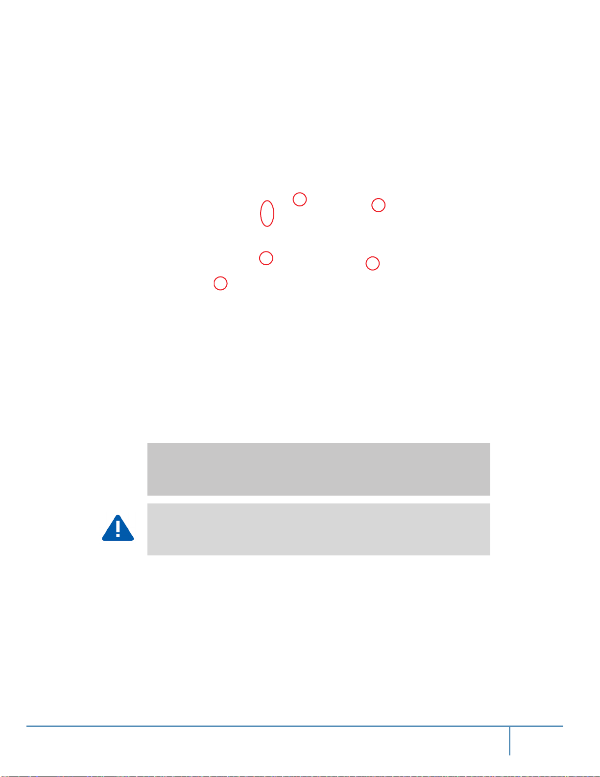
Figure 6: Crate Screws
Installation
Step 4. Remove the nylon covers from the chassis.
Step 5. Visually inspect the chassis, make sure that:
• There is no visible damage
• 10 PSUs are installed
Step 6. Remove all protective plastic film from the sides and top of the chassis.
Unpack the system and check against the parts list to make sure that all the parts have
been sent. Check the parts for visible damage that may have occurred during shipping.
If anything is damaged or missing, contact your customer representative immediately.
Do not remove any of the blocks or the lock-down bars at this time.
27Mellanox Technologies
Page 27

2.5 Physical Installation
The rack mounting holes conform to the EIA-310 standard for 19-inch racks. Guarantee proper ventilation, by leaving 8cm (3”) of space to the front and rear of the switch.
This ensures proper airflow through the chassis. This is crucial for maintaining good
airflow at ambient temperature. In particular, route cables such that they do not impede
the air into or out of the chassis.
Warning: This equipment is very heavy. Make sure that adequate manpower and
proper equipment is used for transporting and moving the chassis. Before attempting to
move and place the chassis make sure that it is empty of all leafs, spines and management modules and to use a mechanical lift.
This chassis can be installed in standard 19” racks that have 715-850mm between the vertical
supports of the rack.
Figure 7: Distance Between the Vertical Supports
Installation
The vertical supports may have to be moved so that the vertical support closest to the door is a
minimum of 6cm from the inside of the door. This is required so that the shelf does not hit the
door.
If you move the vertical supports make sure that you reinstall them vertically plumb.
28Mellanox Technologies
Page 28
Installation
The switch platform uses 29U of rack space, 28U for the chassis and 1U for the shelf. The switch
ships from the factory with mounting holes on the spine side. There are upper brackets to connect
the leaf side to the rack near the top of the chassis, and there are two lock-down bars to secure the
chassis to the shelf. The weight of the switch is supported from underneath the unit by the shelf.
Due to the space required by up to 648 connector cables, it is recommended to use a
rack that is 120cm long and 80cm wide. This should allow for proper cable management and enough ventilation to properly cool the chassis.
Before starting any procedure on the switch system:
1. Put an ESD prevention wrist strap on your wrist, and make sure there
is good contact between
your body and the strap.
2. Plug the other end of the wrist strap to a valid ground. Make sure that this is a tight fit.
You may need a mechanical lift to move and insert the chassis into the rack.
It is recommended to use an AWG6 or 4mm diameter wire for grounding purposes.
2.5.1 Installation Kit Parts
Chassis Installation Kit
Table 5 - Chassis Installation Kit Items
a
Item No.
1 1
2 1
3 1
4 2
5 8
6 8
7 12
Quantity Description Item No. Quantity Description
Shelf assembly
Riveted right chassis slide
Riveted left chassis slide
Support bracket
M5 spring washer
M5 pan-head screw
M6X16 pan-head screw
11 26
12 8
13 1
14 12
15 12
16 18
17 4
M6 spring washer
M6 flat washer
Weld bracket
10-32 hex-head screw
Spring washer #10
M6X25 pan-head screw
Shelf arm bracket
8 30
9 2
M6 cage nut
Perforated fixing bracket
18 2
19 12
Support bracket
Flat washer #10
29Mellanox Technologies
Page 29

Table 5 - Chassis Installation Kit Items
a
Item No.
Quantity Description Item No. Quantity Description
Installation
10 8
a. Use the item number to identify the corresponding item in Figure 8. Each item number appears in a call-out bubble.
M6X16 hex-head screw
–– ––
––––––––––––
Figure 8: Chassis Installation Kit
30Mellanox Technologies
Page 30
Cable Management Installation Kit
Table 6 - Cable Management Installation Kit Parts
a
Item No.
Quantity Description Item No. Quantity Description
Installation
1 1
2 1
a. Use the item number to identify the corresponding item in Figure 9. Each item number appears in a call-out
bubble.
Left riveted cable holder
Right riveted cable holder
3 14
4 14
Pan-head screw
M6 cage nut
Figure 9: Cable Management Installation
31Mellanox Technologies
Page 31

Shelf Installation Kit
The shelf installation kit includes 18 shelves only.
Figure 10: Shelf Installation Kit
Installation
2.5.2 Required Installation Tools
Figure 11 includes the tools which are required for the installation of the director switch chassis.
Figure 11: Tools for Installation
32Mellanox Technologies
Page 32

2.5.3 Installation Procedure
Some of the steps that follow are accompanied by figures that illustrate the installation
of the switch system chassis. For the purpose of clarity, the racks in those figures will
have the side panels removed. You, however, do not need to remove the side panels to
install the switch chassis.
It is recommended to have at least three people for the duration of the installation procedure. Use a mechanical lift to raise this chassis. If not, use enough manpower to
ensure the safety and wellbeing of all of the people involved in the installation.
Step 1. Insert 3 M6 cage nuts each from the inside of BEAM-1 and BEAM-2 on the spine side in
order to support the shelf (Figure 12).
It is recommended to set the shelf at U3 since the chassis would roll off more easily on
it from the pallet.
Installation
Figure 12: Cage Nut Placement for Shelf on BEAM-1 and BEAM-2
33Mellanox Technologies
Page 33

Installation
Step 2. Insert 6 M6 cage nuts from the inside each of BEAM-3 and BEAM-4 on the leaf side in
order to support the shelf (Figure 13).
Figure 13: Cage Nut Placement for Shelf on BEAM-3 and BEAM-4
34Mellanox Technologies
Page 34

Installation
Step 3. Place the top end of the support bracket at the top of U4 using 2 M6x25 screws and 2 M6
flat washers on BEAM-3 and BEAM-4 (Figure 14). Do not tighten the screws completely at
this point.
Figure 14: Cage Nut Placement for Support Bracket
35Mellanox Technologies
Page 35

Installation
Step 4. Insert 6 M6 cage nuts (from the “Chassis Installation Kit Items” box) on the inside of each
of the spine side beams of the rack in the slots indicated in Figure 15.
The indexes in Figure 15 count from the first rack hole above the shelf.
Figure 15: Cage Nut Placement for Switch System Chassis on Spine Side
36Mellanox Technologies
Page 36

Installation
Step 5. Insert 6 M6 cage nuts (from the “Cable Management Installation Kit Parts” box) on the
inside of each of the leaf side beams of the rack in the slots indicated in Figure 16.
The indexes in Figure 16 count from the first rack hole above the shelf.
Figure 16: Cage Nut Placement for Cable Holders on Leaf Side
37Mellanox Technologies
Page 37

Installation
Step 6. Using a ratchet wrench, loosen the shelf arms’ M6 hex screws enough to allow for slight
movement (Figure 17).
Figure 17: Loosening the Leaf-Side Shelf Arms
38Mellanox Technologies
Page 38

Installation
Step 7. Adjust the shelf’s leaf-side arms so that the distance between the leaf-side and spine-side
arms is at least 5mm longer than the distance between the rack beams (Figure 18).
Figure 18: Adjusting the Leaf-Side Shelf Arms
39Mellanox Technologies
Page 39

Step 8. Place the shelf in U3 of the rack by inserting it at a tilt (Figure 19).
At least 2 people are necessary for installing the shelf.
Figure 19: Placing Shelf
Installation
40Mellanox Technologies
Page 40

Installation
Step 9. Assemble the spine-side M6X25 pan-head screws and the arm brackets at an intermediate
3Nm torque (Figure 20).
Figure 20: Tightening Shelf Cage Nut Screws on Spine Side
Step 10. Assemble the leaf-side M6X25 pan-head screws and the arm brackets at 3Nm torque
(Figure 21).
Figure 21: Tightening Shelf Cage Nut Screws on Leaf Side
41Mellanox Technologies
Page 41

Installation
Step 11. Tighten the M6X25 pan-head screws of the shelf arms on the spine side at 9Nm torque
(Figure 22).
Figure 22: Tightening Spine-side Shelf Arm Screws
Step 12. Screw in 4 more M6X25 pan-head screws in the support brackets as fasteners from the leaf
side at 3Nm torque (Figure 23).
Figure 23: Screwing Leaf-side Fasteners
42Mellanox Technologies
Page 42

Installation
Step 13. Tighten the 10 hex head screws of the shelf’s leaf-side arms at 9Nm torque on both sides
(Figure 24).
Figure 24: Tightening Spine-side Shelf Arm Screws
43Mellanox Technologies
Page 43

Installation
Step 14. Tighten the 12 M6X25 pan-head screws of the shelf’s leaf-side arms at 9Nm torque now
that the shelf has been placed (Figure 25).
Figure 25: Tightening Leaf-side Shelf Screws
44Mellanox Technologies
Page 44

Installation
Step 15. Assemble the bracket weld to the shelf on the spine side and tighten at 5Nm with 2 hex
screws, 2 spring washers and 2 flat washers.
Figure 26: Weld Bracket Assembly
45Mellanox Technologies
Page 45
Installation
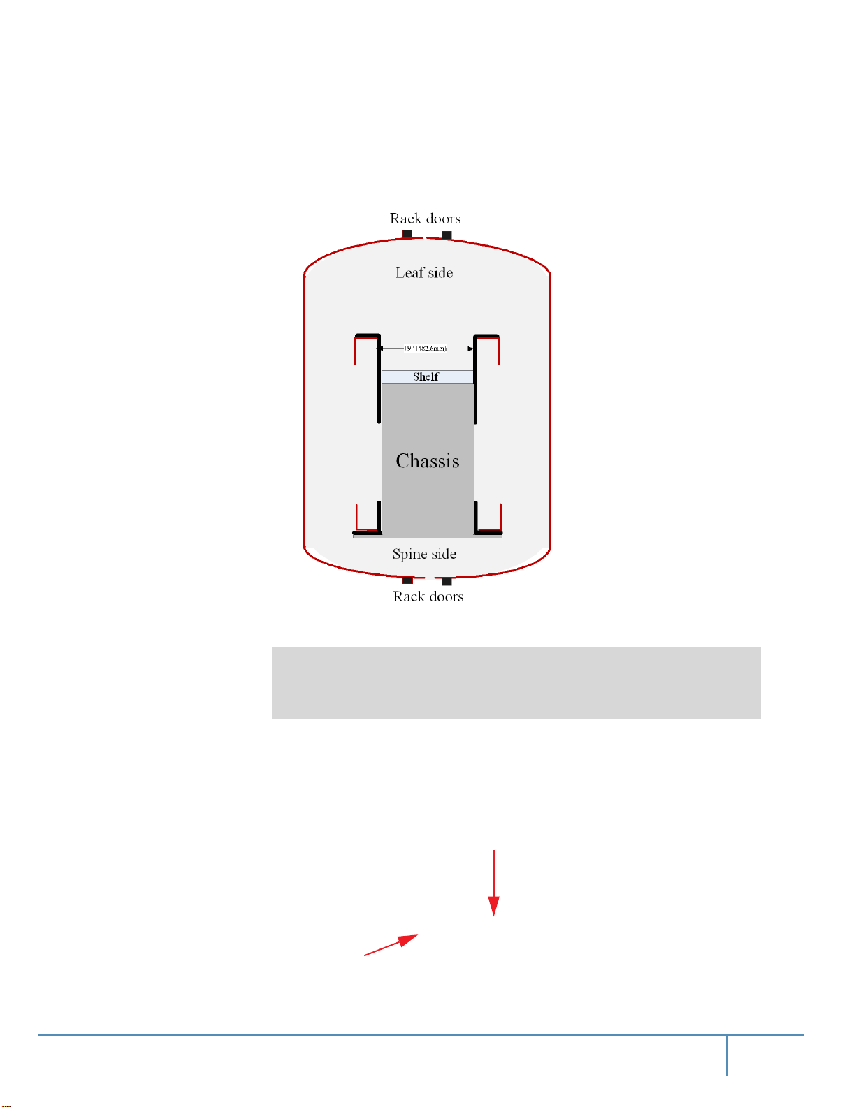
Step 16. Before placing the chassis in the rack, make sure to leave more room on the leaf (port
cables) side to allow room for cable management.
Figure 27: Placement of Chassis in Rack – Top View
Step 17. Put the crate on the fork lift or a mechanical lift.
From Step 16-Step 24, 3 people should participate in the installation process.
Figure 28: Fork Lift
Wooden
Hinged exten-
46Mellanox Technologies
Page 46

Figure 29: Mechanical Lift
Step 18. Position the chassis in front of the installation rack (Figure 30).
Step 19. Unscrew both lock-down bars.
Installation
The chassis is on ball bearings and can roll easily. Beware that the chassis can roll off
of the pallet possibly causing grave bodily harm should it fall on someone.
Step 20. Using a fork or mechanical lift, position the middle of the leaf-side of the chassis in front of
the spine-side of the rack (Figure 30).
Figure 30: Rack and Chassis Alignment
47Mellanox Technologies
Page 47

Step 21. Place the rotated strip on top of the bracket weld (Figure 31).
Figure 31: Rotated Strip and Bracket Weld
Installation
Step 22. Unscrew the lock-down bar facing the rack.
Note that the chassis is on ball bearings, and with the lock-down bars removed, the chassis
can roll off!
48Mellanox Technologies
Page 48

Step 23. Slide the switch system chassis halfway into the rack (Figure 32).
Push only from the spine side so as to not injure your fingers during insertion.
Figure 32: Sliding Chassis in Rack
Installation
49Mellanox Technologies
Page 49

Step 24. Slide the switch system chassis all the way into the rack until it stops.
Beware not to injure your fingers during insertion.
Step 25. Slide in the left and right chassis slides from the leaf side (Figure 33).
Figure 33: Sliding in Chassis Slides
Installation
50Mellanox Technologies
Page 50

Step 26. Slide the switch system chassis all the way into the rack (Figure 32).
Figure 34: Sliding Chassis into Rack
Installation
51Mellanox Technologies
Page 51

Installation
Step 27. Screw the chassis to the rack on the spine side using 12 M6X16 screws where the cage nuts
have been placed at 9Nm torque.
Figure 35: Screwing the Chassis to the Rack
52Mellanox Technologies
Page 52

Installation
Step 28. Assemble the 2 4-oval washer plates to the left and right chassis slides on the leaf side
(Figure 36) at 3.23-3.58Nm torque using 4 M5 pan-head screws on each side (Figure 36).
Figure 36: Screwing the 4-Oval Washer Plates
53Mellanox Technologies
Page 53

Installation
Step 29. Remove the M6X16 screws holding the weld bracket on the spine side using a ratchet
wrench (Figure 37).
Figure 37: Removing the Weld Bracket
54Mellanox Technologies
Page 54

Installation
Step 30. Place the perforated fixing bracket on the shelf from the leaf side and assemble it using a
ratchet wrench (with 8mm socket) and 6 10-32 hex screws, 6 #10 flat washers, and 6 #10
spring washers to the chassis at 3.23-3.58Nm torque (Figure 38).
Figure 38: Leaf Side Fixing Bracket With Chassis
55Mellanox Technologies
Page 55

Installation
Step 31. Place the perforated fixing bracket on the shelf from the spine side and assemble it using 6
10-32 hex screws, 6 #10 spring washers, and 6 #10 flat washers to the chassis at 3.23-
3.58Nm torque (Figure 39).
Figure 39: Spine Side Fixing Bracket With Chassis
56Mellanox Technologies
Page 56

Installation
Step 32. Screw the perforated fixing bracket on the leaf side to the shelf at 9Nm torque (Figure 40).
Figure 40: Leaf Side Fixing Bracket With Shelf
57Mellanox Technologies
Page 57

Installation
Step 33. Screw the fixing bracket on the spine side to the shelf using 3 M6X16 hex screws, 3 M6
spring washers, and 3 M6 flat washers at 9Nm torque (Figure 41).
Figure 41: Spine Side Fixing Bracket With Shelf
58Mellanox Technologies
Page 58

Installation
Step 34. Assemble the cable holders to the leaf-side rack using 14 M6X16 pan-head screws at 9Nm
torque (Figure 42).
Figure 42: Installing Cable Holders
2.6 Ground Connections
Make sure to connect the ground post to a valid electrical ground. Use a grounding lug and a
ground wire of sufficient capacity to safely convey a potential discharge. The grounding post is
M-8 with 1.25mm pitch threads. A ground wire of AWG 6 or 4mm diameter is recommended for
59Mellanox Technologies
Page 59

Installation
grounding this device. The chassis is concurrently grounded through each of the PSUs. Only connect the PSU cords to properly grounded outlets. Do not rely on the
PSU grounds. It is absolutely
necessary to connect the grounding post. Make sure the connections are solid and permanent. If
you choose to not use the ground screw, make sure that the rack is properly grounded and that
there is a valid ground connection between the chassis of the switch and the rack.
Warning: System grounding must comply with local electrical code.
Figure 43: Grounding Posts
Ground-
ing post
2.7 FRU Insertion and Extraction (Hot-Swappable)
Before starting any procedure on the switch system, put an ESD prevention wrist strap on your
wrist and connect to the chassis.
Do not mix replacement parts based on different generations of chip.
All replacement modules must be consistent with the chassis family and switch chip
generation.
When hot-swapping any of the units, it is necessary to wait 1 minute after removing
the defective part before inserting the new part. This is necessary so that the management module will start a new cycle checking through the leafs and spines for the FW
versions.
This switch platform supports hot swap capabilities for the following parts:
• Power supply units
• Leaf modules
Grounding post
•
Spine modules
• Leaf fan modules
• Spine fan modules
• Management modules
For information on the ordering part numbers for these field replaceable
Appendix G, “Replacement Parts Ordering Numbers,” on page 107.
units
(FRUs), see
60Mellanox Technologies
Page 60

2.7.1 Power Supply Units
The power supplies deliver 2500W at 48VDC. The input to each of these power supplies requires
12A current in order to output 2500W.
For N+N configuration up to half of the PSUs can go down and the system will continue to run.
The power required to run the switch system is equally divided between
2.7.1.1 Extracting and Inserting the PSU
A new system would have the PSU already installed so there
With all of the N+N 2500W power supplies installed, the system is in N +N redundant configuration, half of the PSUs may be extracted without bringing down the system.
To extract a PSU:
Step 1. Determine which AC connector on the connector side of the chassis corresponds to the
defective PSU.
Step 2. Remove the power cord from the PSU’s inlet. Note which power cord it is according to the
AC numbering.
all
of the working PSUs.
Installation
Figure 44: Power Unit AC Inlet Numbering
Step 3. On the spine side of the chassis, remove the cover to the PSUs. There are four Phillips head
screws for the cover plate.
Figure 45: Power Supply Unit
Han-
Latch
Step 4. Grasping the handle with one hand, push the black latch release while pulling the handle
outward. As the PSU unseats, the PSU status indicators will turn off.
Step 5. Remove the PSU.
To insert a power supply unit:
61Mellanox Technologies
Page 61

Step 1. Make sure the mating connector of the new unit is free of any dirt and/or obstacles.
Step 2. Insert the PSU by sliding it into the opening until a slight resistance is felt.
Step 3. Continue pressing the PSU until it seats completely. The latch will snap into place confirm-
ing the proper installation.
Step 4. Insert the power cord into the supply connector on the other side of the chassis.
Step 5. Replace the cover over the PSUs.
The green indicators should light. If not, extract the PSU and re-insert it again.
2.7.2 Leaf Modules
When hot-swapping any of the units, it is necessary to wait 1 minute after removing
the defective part before inserting the new part. This is necessary so that the management module will start a new cycle checking through the leafs and spines for the FW
versions.
Installation
Use only Switch-IB™ and Switch-IB™ 2 based ASICs, Do NOT use replacement
parts based on different generations of chipsets.
All replacement modules must be consistent with the chassis family and switch chip
generation.
Leaf module slots are numbered from top to bottom from L1 to L9 on both sides of the chassis.
2.7.2.1 Extracting a Leaf Module
Each leaf module has 2 ejector handles that locks the module in
seating or extracting (see Figure 46).
Step 1. Run the shut down command “no power enable <module>”. For example to shut down
leaf 16 run the command below.
switch [master] (config) # no power enable L16
Step 2. Disconnect all cables connected to the leaf.
Step 3. Push the ejector handles in the direction of the red arrows in Figure 46 and pull them out-
wards to unlock the ejectors from the chassis.
Figure 46: Releasing Leaf Ejector Handles
Push in this direc-
and serve as a lever for
place
Push in this direc-
Step 4. Open the ejectors until it is 45 degrees from the leaf.
Step 5. Pull out the module halfway through the guiding rails using the ejector handles.
62Mellanox Technologies
Page 62
Step 6. Re-lock the ejector handles.
Step 7. Hold the body of the leaf on both sides and remove it from the chassis.
The module is short, therefore do not let go of it while sliding it out.
2.7.2.2 Inserting a Leaf Module
When hot-swapping any of the units, it is necessary to wait 1 minute after removing
the defective part before inserting the new part. This is necessary so that the management module will start a new cycle checking through the leafs and spines for the FW
versions.
To insert the leaf module:
Step 1. Check for foreign objects in or mechanical damage to the chassis leaf slots.
Step 2. Check leaf mechanics for any noticeable damage.
Step 3. Check back signal connectors’ integrity. Look for any broken signal dividers or any devia-
tions from the pass criterion shown in Figure 47.
Installation
Figure 47: Intact Leaf Signal Connectors
Step 4. Check power connector’s integrity. Look for any damage on the power connector casing or
blades damage.
Figure 48: Intact Leaf Power Pins
Step 5. Start with the ejector handles fully open; that is, at 45 degrees to the front panel of the leaf.
Step 6. Holding the leaf by its sides, carefully set the leaf module halfway into the chassis.
63Mellanox Technologies
Page 63
Installation
Step 7. Applying equal pressure on both sides of the leaf module, and using only the ejector han-
dles, slowly slide the module into the chassis until the ejector handles reach the vertical bar.
Do not apply excessive force to slide in the leaf module. If you feel resistance,
remove the leaf module and double check both the chassis and leaf for any damage.
Step 8. Catch the ejector handle hooks onto the vertical bar of the chassis and push the ejector han-
dles shut (Figure 49).
Figure 49: Leaf Module Insertion
Vertical
Ejector handle hooks
Locking mecha-
Ejector han-
Step 9. Lock the ejector handles onto the module.
2.7.3 Spine Modules
Use only Switch-IB™ and Switch-IB™ 2 based ASICs, Do NOT use replacement
parts based on different generations of chipsets.
All replacement modules must be consistent with the chassis family and switch chip
generation.
When hot swapping any of the units, it is necessary to wait 1 minute after removing the
defective part before inserting the new part. This is necessary so that the management
module will start a new cycle checking through the leafs and spines for the FW versions.
Each spine has a pair of ejectors that lock the module in place and serve as levers for seating or
extracting (see Figure 51).
Management module 1 is connected to spine module 1, and management module
to spine module 2. All of the spine modules can be hot-swapped when these two management
modules are installed and working.
When a slave management module is not installed or not working, the spine module
connected to the master management module cannot be hot-swapped.
2 is connected
Spine module slots are numbered from top to bottom from S1 to S9 on both sides of the chassis.
64Mellanox Technologies
Page 64
2.7.3.1 Extracting a Spine Module
When a slave management module is not installed or not working, hot-swapping the
spine module connected to the master management module will cause the chassis to
crash.
Neither the CLI nor the GUI management tools will allow you to shut down spine #1
or spine #2, as the management modules are connected to the chassis components
through these spines.
Extracting Spine Module #1 or #2
Spine module #1 is connected to management module #1 and spine module #2 is connected to
management module #2.
Figure 50: Management Module Numbering
Installation
MNG1
Mgmt module
MNG2
Mgmt module
Removing spine #1 causes management module #1 to reset.
Removing spine #2 causes management module #2 to reset.
Warning: If the spine you want to hot swap is connected to the master management
module the management module will reboot when you take out the spine.
Do not extract spine 1 or 2 if only one management module is connected! Doing so
will cause the switch system to hang which will lead to traffic loss.
If you need to hot swap spine #1 or spine #2:
Step 1. Make sure that two management modules are connected to the switch system. See
Figure 50.
65Mellanox Technologies
Page 65
Installation
Step 2. Extract the spine module according to the procedure in “Extracting Spine Modules Except
#1 or #2” starting with Step 2 (without running the shutdown command).
Traffic loss and errors in the log may be experienced momentarily.
Extracting Spine Modules Except #1 or #2
Step 1. Run the shutdown command
no power enable <module>
. To shut down spine 06, for
example, run:
switch [master] (config) # no power enable S06
Step 2. Push the ejector handles in the direction of the red arrows in Figure 51 and pull them out-
wards to unlock the ejectors from the chassis.
Figure 51: Releasing Spine Ejector Handles
Push in this direc-
Step 3. Open the ejectors until they are at a 45 degree angle from the module.
Do not use the fan FRU handle to extract the spine module.
Push in this direc-
Step 4. Pull out the module halfway through the guiding rails using both ejectors.
Step 5. Re-lock the ejector handles.
Step 6. Hold the body of the module on both sides and remove it from the chassis.
2.7.3.2 Inserting a Spine Module
When hot-swapping any of the units, it is necessary to wait 1 minute after removing
the defective part before inserting the new part. This is necessary so that the management module will start a new cycle checking through the leafs and spines for the FW
versions.
To insert a spine module:
Step 1. Check for foreign objects in or mechanical damage to the chassis spine slots.
Step 2. Check back signal connectors’ integrity. Look for any broken signal dividers or any devia-
tions from the pass criteria shown in Figure 52.
66Mellanox Technologies
Page 66
Installation
Figure 52: Intact Spine Signal Connectors
Step 3. Check power connector’s integrity. Look for any damage on the power connector casing or
blades damage, or any deviations from the pass criterion shown in Figure 53.
Figure 53: Intact Spine Power Pin Holders
Step 4. Start with the ejector handles fully open; that is, at 45 degrees to the front panel of the spine.
Do not use the fan FRU handle to insert the spine module.
Step 5. Holding the spine by its sides, carefully set the spine module halfway into the chassis.
Step 6. Using only the ejector handles, slowly slide the module into the chassis until the hooks
reach the vertical bar.
Do not apply excessive force to slide in the spine module. If you feel resistance,
remove the spine and double check both the chassis and spine for any damage.
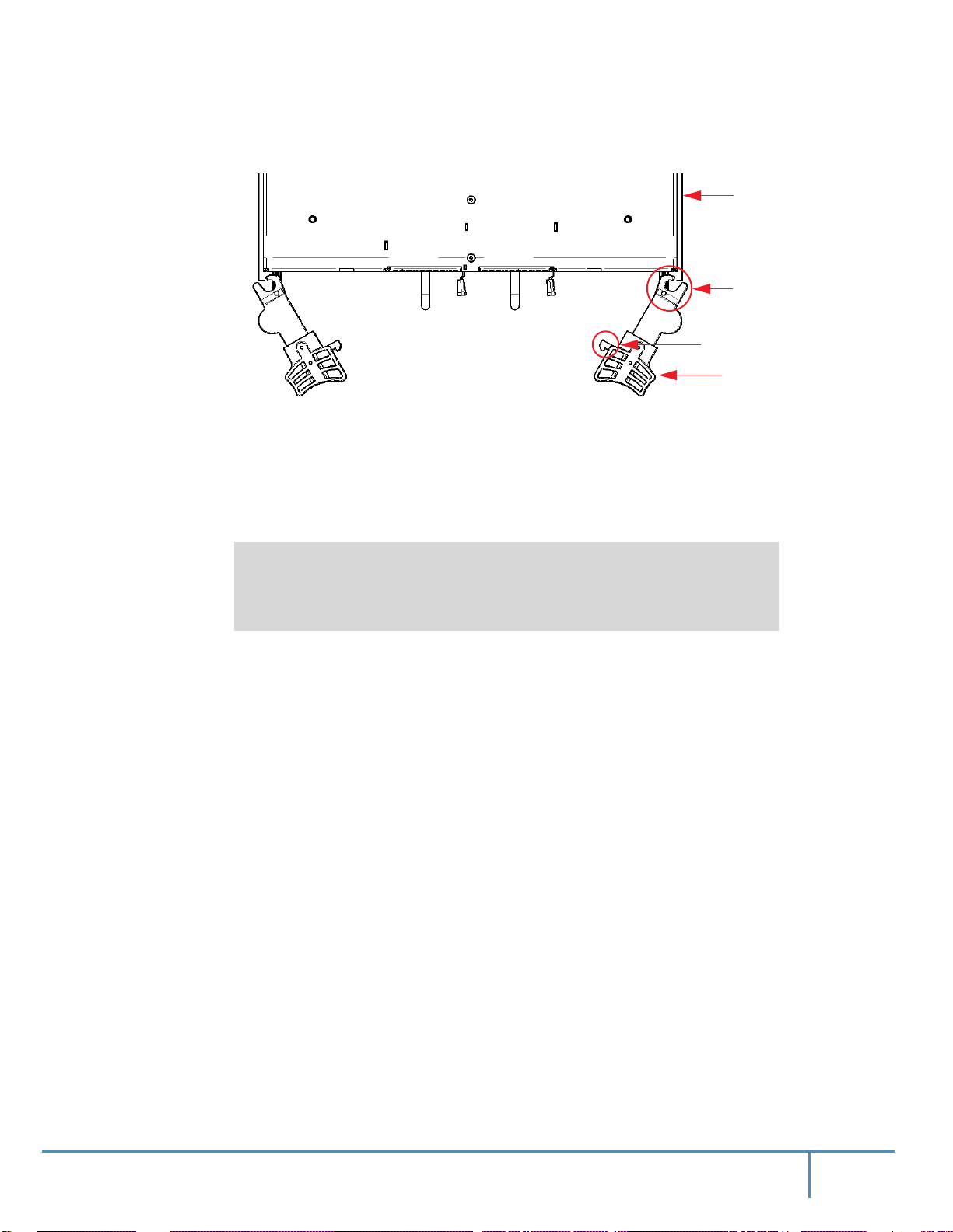
Step 7. Catch the ejector handle hooks onto the vertical bar of the chassis and push the ejector han-
dles shut (Figure 54).
67Mellanox Technologies
Page 67
Step 8. Lock the ejector handles onto the module.
2.7.4 Fan Modules
2.7.4.1 Leaf Fan Module
Installation
Figure 54: Spine Module Insertion
Vertical
Ejector handle hooks
Locking mecha-
Ejector han-
A new system would have the PSU already installed so there
There are 12 fan modules on the chassis for the leaf and management modules. They are located
on the spine side of the chassis with 6 on the right of the spines, and 6 on the left. When a fan
module is not functioning the status LED on the fan will light up in amber. Airflow through the
spines is independent of the airflow through the leafs.
68Mellanox Technologies
Page 68
Figure 55: Leaf Fan Locations on the Chassis
Installation
Extracting the Leaf Fan Module
Step 1. Push and hold the blue latch release. See Figure 56.
Step 2. Slowly pull out the fan module using the handle.
Figure 56: Leaf Fan Module Extraction
Latch
Releas
Han-
69Mellanox Technologies
Page 69

Inserting the Leaf Fan Module
When hot-swapping any of the units, it is necessary to wait 1 minute after removing
the defective part before inserting the new part. This is necessary so that the management module will start a new cycle checking through the leafs and spines for the FW
versions.
Step 1. Confirm that the location of the connector in the chassis lines up with the connector in the
fan module.
Step 2. Slowly slide in the new leaf fan module.
Step 3. Push the fan module until the latch engages.
Step 4. Make sure that the green fan LED on the module comes on (indicating that fan is running).
2.7.4.2 Spine Fan Modules
Installation
If the fan module stops before it goes in all of the way it is inserted incorrectly.
Each spine has 2 individual fan modules that contain 2 individual
each. Should a single fan
fans
fail the fan status LED on the spine and the fan status LED on the management module light up,
indicating the necessity to replace the fan module. Airflow through the spines is independent of
the airflow through the leafs.
Figure 57: Spine Fan Modules
LatcHan-
When a fan module is removed the indicator light will reset.
Figure 58: Fan Status LED on the Spine Module
Fan LED #1 Fan LED #2
70Mellanox Technologies
Page 70

Installation
Extracting the Spine Fan Module
To extract the spine fan module push the blue latch button while pulling the fan module out.
Inserting the Spine Fan Module
When hot-swapping any of the units, it is necessary to wait 1 minute after removing
the defective part before inserting the new part. This is necessary so that the management module will start a new cycle checking through the leafs and spines for the FW
versions.
Step 1. Make sure the fan module is oriented correctly with the release latch on the right. Confirm
that the location of the connector in the chassis will line up with the connector in the fan
module.
Step 2. Slowly slide in the new spine fan module.
Step 3. Push the fan module as far as it will go, make sure the locking latches engage.
If the fan LED continues to show amber remove the fan module and check the pins on
the connector inside of the spine to make sure that none of them are bent.
2.7.5 Management Module
When hot-swapping any of the units, it is necessary to wait 1 minute after removing
the defective part before inserting the new part. This is necessary so that the management module will start a new cycle checking through the leafs and spines for the FW
versions.
Extracting a Management Module
Management modules are located on the leaf side, above the leafs. There are two slots to install
the management modules.
Only one management module is required to run the switch system.
If only one management module is used, the other management slot should be covered
using a management blank unit.
Each management module has a pair of ejectors that lock the module in place and serve as a lever
for seating or extracting (see Figure 59).
71Mellanox Technologies
Page 71
Installation
Step 1. Run the shut down command
no power enable <module>
. For example to shut down
management module 2, run.
switch [master] (config) # no power enable mgmt2
Step 2. Disconnect all cables connected to the management module.
Step 3. Push the ejector handles in the direction of the red arrows in Figure 59 and pull them out-
wards to unlock the ejectors from the chassis.
Figure 59: Releasing Management Ejector Handles
Push in this direc-
Step 4. Open the ejectors until they are 45 degrees from the module.
Step 5. Pull out the module halfway through the guiding rails using the ejector handle.
Step 6. Lock the ejector handle.
Step 7. Hold the body of the module on both sides and remove it from the chassis.
The module is short, therefore do not let go of it while sliding it out.
Push in this direc-
Inserting a Management Module
When hot-swapping any of the units, it is necessary to wait 1 minute after removing
the defective part before inserting the new part. This is necessary so that the management module will start a new cycle checking through the leafs and spines for the FW
versions.
To insert a management module:
Step 1. Check for foreign objects in or mechanical damage to the chassis management slots.
Step 2. Check management mechanics for any noticeable damage.
Step 3. Check back signal connectors’ integrity. Look for any broken signal dividers or any devia-
tions from the pass criterion shown in Figure 60.
Figure 60: Intact Signal Connectors
Step 4. Check power connector’s integrity. Look for any damage on the power connector casing or
blades damage, or any deviations from the pass criterion shown in Figure 61.
72Mellanox Technologies
Page 72
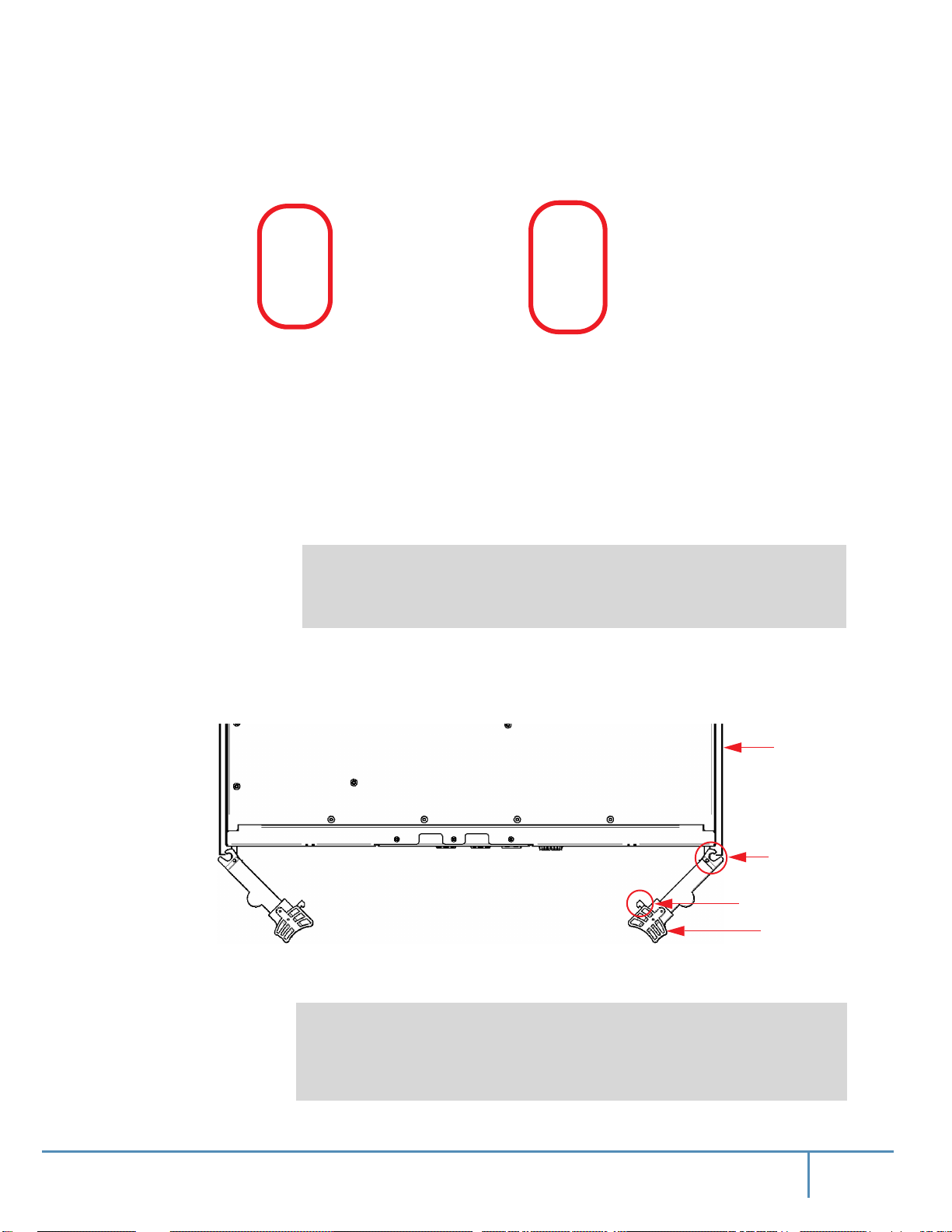
Installation
Figure 61: Intact Management Power Pins
Step 5. Start with the ejector handles fully open; that is, at 45 degrees to the front panel of the man-
agement.
Step 6. Holding the management by its sides, carefully set the management module halfway into
the chassis.
Step 7. Using only the ejector handles, slowly slide the module into the chassis until the hooks
reach the vertical bar.
Do not apply excessive force to slide in the management module. If you feel resistance, remove the management and double check both the chassis and management
module for any damage.
Step 8. Catch the ejector handle hooks onto the vertical bar of the chassis and push the ejector han-
dles shut (Figure 62).
Figure 62: Management Module Insertion
Vertical
Ejector handle hooks
Locking mecha-
Ejector han-
Step 9. Lock the ejector handles onto the module.
On switch systems with dual management systems, first connect the cable and configure
the master management module and only then configure the slave. By default the master
is the top management module. For further information on the master and slave roles,
see section “Subnet Manager (SM) High Availability (HA)” of the MLNX-OS® User
Manual.
73Mellanox Technologies
Page 73

All management modules in the chassis must go through an initial configuration procedure. See the Installation Guide for the initial configuration procedure.
2.8 InfiniBand QSFP Cable Installation
The switch uses industry standard QSFP InfiniBand cables which are available from Mellanox
Technologies. The Mellanox proprietary QSFP cables support full 100+100Gb/s (EDR),
56+56Gb/s (FDR), 40+40Gb/s (FDR10), 40+40Gb/s (QDR), 20+20Gb/s (DDR) and 10+10Gb/s
(SDR) bidirectional wire speed of the switch ports. All InfiniBand QSFP connections are made to
the leaf modules. Each leaf has 18 InfiniBand QSFP connectors in two rows, which are numbered 1-18. See Section 3.1.7 for port numbering.
If maximum cable lengths are exceeded data transfer will be reduced and the bit error
rate will increase.
Installation
EDR is only guaranteed to work with approved Mellanox cables.
All cables can be inserted or removed with the unit powered on. To insert a cable, press the connector onto the port receptacle until the connector is firmly seated. The
orange LED indicator
above the port will light when the physical connection is established (when both ends of the cable
are properly connected to working devices). Allow 15 seconds for link to get up. To remove, disengage the lock and slowly pull the connector away from the port receptacle.
For a valid physical connection both ends of the cable must be connected to working
devices.
Careful to not impede the airflow through the ventilation holes next to the InfiniBand
ports. Use cable lengths which allow routing horizontally around to the side of the
chassis before bending upward or downward in the rack.
74Mellanox Technologies
Page 74

2.9 Cable Holder Placement
After connecting the power cords, you may place the 18 cable supporters onto the cable holders
(Figure 63).
Figure 63: Cable Supporter Placement
Installation
2.9.1 Supported Approved Cables
For a list of approved cables for this switch see the Mellanox approved cable list.
http://www.mellanox.com/page/cables?mtag=cable_overview
75Mellanox Technologies
Page 75

2.9.2 Cable Power Classes
Chassis and switches need to be able to dissipate the heat generated by high power I/O cables and
modules. The Mellanox CS75x0 series chassis are rated for cables up to class 4 as per the SFF
committee classification (
SFF-8436.PDF).
2.10 Power Connections
This section assumes that the power cords are not connected to the power main. Once
system assembly is finished please refer to Chapter 4, “Chassis Power Up,” on page 88
to power the system up.
The switch includes 10 hot-swap power supply units (PSUs). Each PSU has its dedicated AC
inlet. The system uses C20 type inlets. The design enables optional use of separate main and
backup AC feeds. The AC power source should comply with 180-265VAC 50Hz or 60Hz characteristics.
C19 to C20 type power cords, 15A rated, should be used to connect system
maximum power consumption of each power supply is 12A. Ensure all 10 power cords are firmly
connected to inlets.
Installation
to AC power. The
Figure 64: AC Inlets
Make sure that the power cords are compatible with your outlets. Power cords for different countries can be ordered from Mellanox.
Make sure that the outlets and circuits are not overloaded. Spread out the load over at
least two or three circuits or use a 3 phase circuit.
76Mellanox Technologies
Page 76

3 Interfaces
3.1 LED Status Indicators
The LEDs are placed on the chassis for the convenience of the IT manager. All chassis conditions
and management options are available and controllable through the management software, either
CLI or WebUI.
It is recommended that all of the chassis subsystems be maintained and managed
through the management software.
3.1.1 Power Supply Unit LEDs
The PSUs are on the spine side of the chassis at its upper side and are behind two cover panels.
The plugs for these PSUs are on the leaf side of the chassis.
Each power supply unit has the following LED indicators.
Figure 65: Power Supply Unit Status Indications
Interfaces
• AC OK – LED indicator
• Green – when input voltage is 85V
< Vin < 270V
AC
• Off – when input voltage is 85VAC > Vin or Vin > 270V
• DC OK – LED indicator
• Green – when output voltage above 90%+/- 5% of 48V
• Red – when output voltage fallen below 90%+/- 5% of 48V
AC
AC
DC
DC
77Mellanox Technologies
Page 77
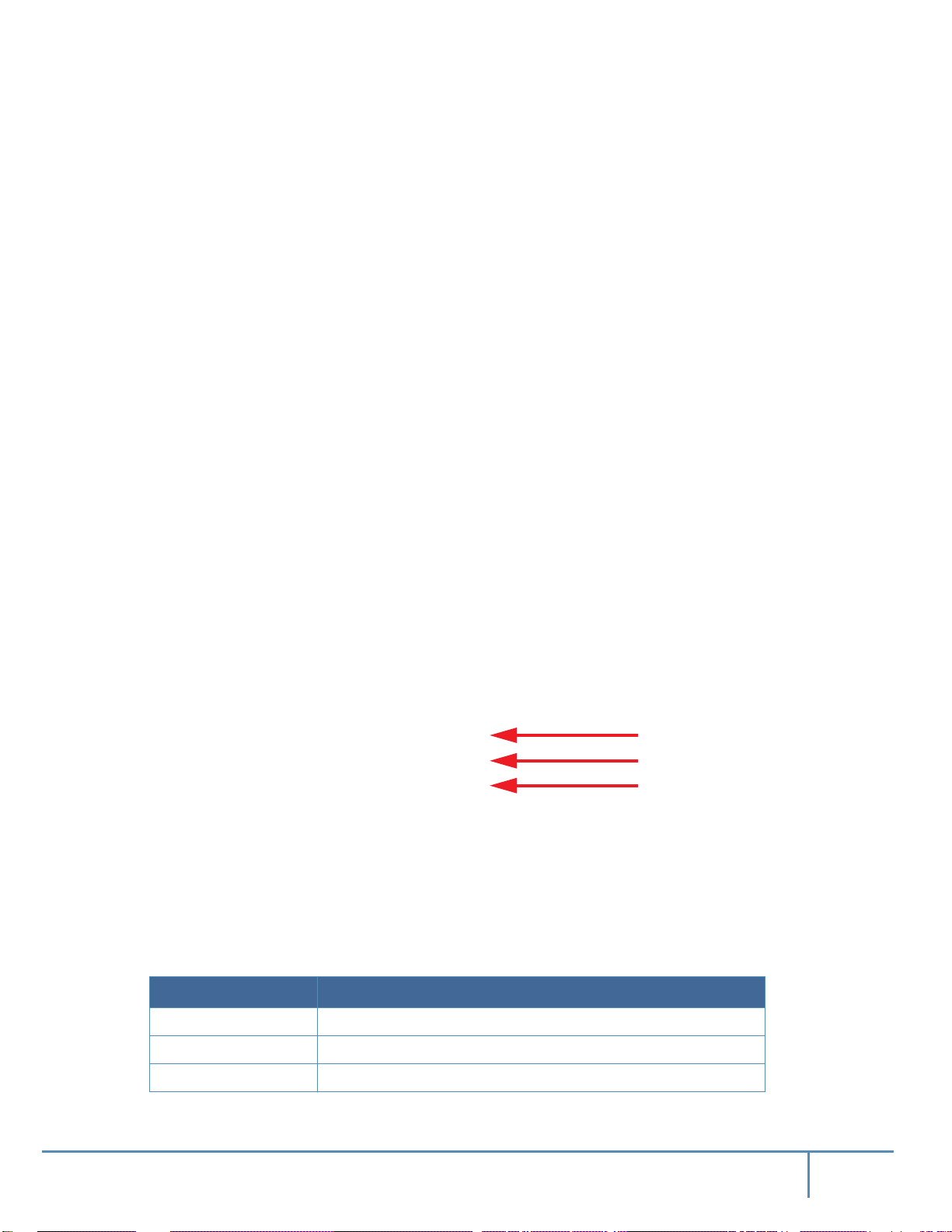
Figure 66: CS7510 PSU Cover
3.1.2 System AC Power Interface
Each PSU in the switch system has a dedicated AC inlet. The inlets are numbered, 1 through 10,
corresponding to the numbers on the PSU covers. The system utilizes C19/C20 AC inlet standard
where C20 socket is installed on the system. A C19-to-C20 power cord is provided with the system. An appropriate capacitor discharge unit (CDU) should be installed to interface with the system.
Interfaces
3.1.3 Leaf Module LED Indicators
Figure 67: Leaf Module LED Indicators
3.1.3.1 Status LED
The Status LED is located in the middle of the leaf to allow easier visibility
installed.
The leaf Status indicator LED has the following LED assignment:
Table 7 - Leaf Status LED
LED Condition Description
Off No power to the leaf
Green: Solid Leaf is up and running
Green: Flashing Leaf is booting or being restored to factory default
Leaf Status LED
Bad Port LED
UID LED
when all cables are
78Mellanox Technologies
Page 78
Table 7 - Leaf Status LED
LED Condition Description
Amber: Solid Fatal error
3.1.3.2 Bad Port LED
The Bad Port LED is located on the left side of the leaf. The following Bad Port LED conditions
are possible.
Table 8 - Bad Port LED Configurations
LED Condition Description
Off OK: All ports are up and running
Amber: Flashing Error: One or possibly more ports has just received a symbol
This LED shows symbol errors. Possible causes for this are:
• bad cable
•
bad connection
Interfaces
error
bad connector
•
This LED lights up when one or more ports is receiving a symbol
goes off until the next symbol error is received.
3.1.3.3 UID LED Switch Identifier
The UID LED is a debug feature that will become available to customers in
details please contact Mellanox Technologies support.
3.1.3.4 Leaf Module Port Connector LED Assignment
Above the ports are two LEDs one for the upper port
has a single 2 color LED. Table 9 presents the link status according to the LED condition.
Table 9 - Connector Physical and Logical Link Indications
LED Condition Description
Off No power to the port
Green: Solid Logical link up
Green: Flashing Data activity: Flashing frequency is proportional to data transfer
speed
Amber: Solid Physical link up
. The LED immediately
error
the near future. For
and one for the lower port . Each port
Amber: Flashing A problem with the physical link
The LED indicator, corresponding to each data
port, will light orange when the physical connec
tion is established (that is, when the unit is powered on and a cable
-
is plugged into the port with
79Mellanox Technologies
Page 79
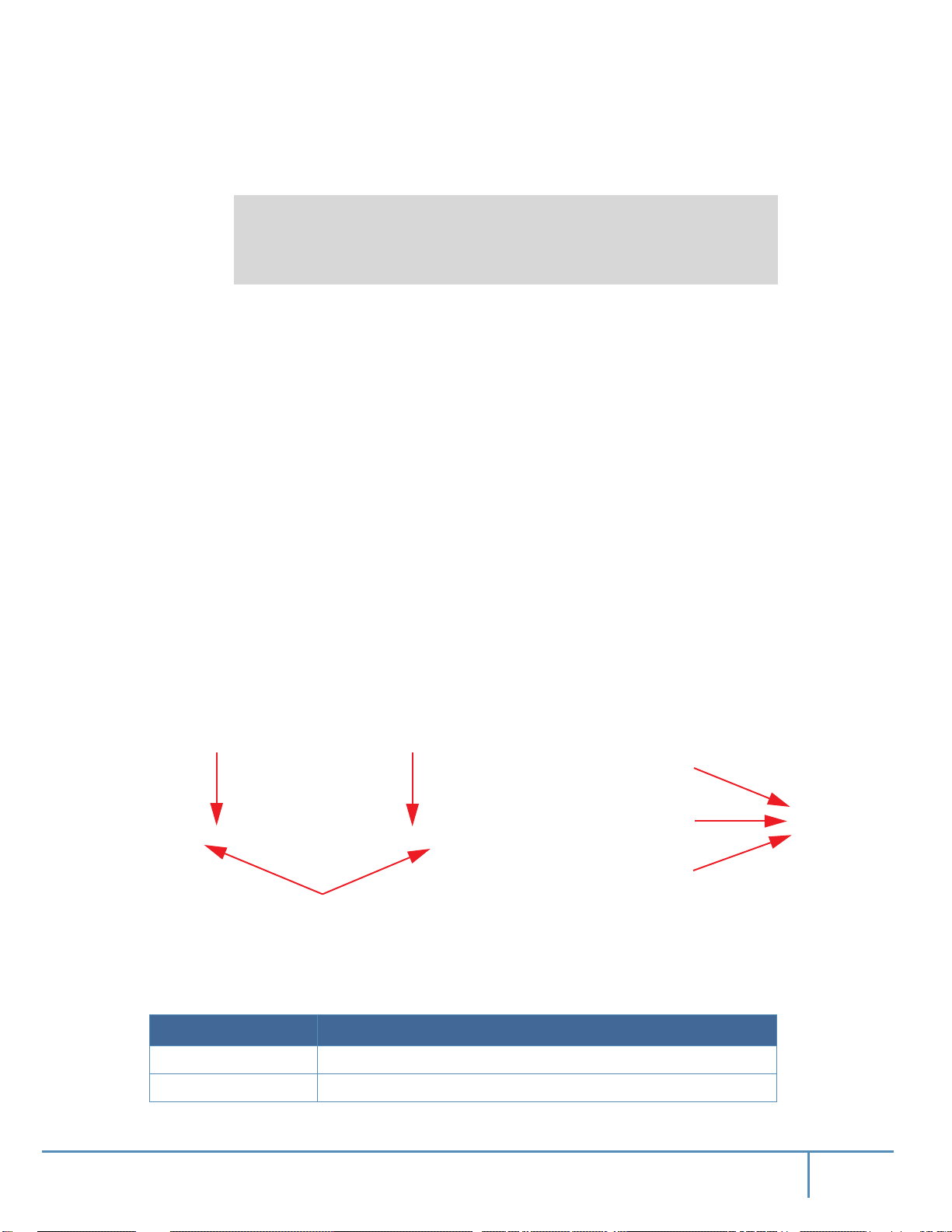
the other end of the connector plugged into a functioning port). When a logical connection is
made the LED will change to green. When data is being transferred the light will blink green.
The switch does not provide a visual means to indicate the port speed configuration
(SDR, DDR, QDR, FDR, or EDR) and/or the link width (1X or 4X). The speed and
link width configurations can be retrieved using management software.
3.1.4 Spine Module LED Indicators
Each leaf module is connected by links to each spine module. Each spine has the following
LEDs.
• One status LED for the spine health
• T
wo status LED for the spine fan modules, one per module
• 36 status LEDs showing the existence of leaf to spine connections
• One Bad Port LED showing symbol errors in the data stream
• One UID LED that can be lit to identify an individual spine
Interfaces
The 36 LEDs on each spine are divided by the number of leafs and
connections from each leaf that are connected to the spine. All spines must be installed and working to ensure that full BW exists between nodes. The maximum number of
each leaf is 1. If the (number of leafs) x (the maximum number of connections per leaf) is less
than 36 then some of the leaf to spine connection LEDs may be OFF.
The status LEDs for the spine and their descriptions are shown in Table 10. The LEDs indicate as
follows.
Leaf Fan #1 LED Leaf Fan #2 LED
3.1.4.1 Status LED
Table 10 shows the spine status according to the LED condition.
Table 10 - Spine Status LED
Figure 68: Spine Status LEDs
Leaf connection status
the
result (N) is the number of
Spine Status LED
Bad Port LED
UID LED
connections from
LED Condition Description
Off No power to the spine
Green: Solid Spine is up and running
80Mellanox Technologies
Page 80
Table 10 - Spine Status LED
LED Condition Description
Green: Flashing Spine is powering up or being restored to factory default
Amber: Solid Fatal error
3.1.4.2 Fan LED
Interfaces
For each fan drawer in the spine there is a status LED. The spine fan
lowing LED assignment.
Table 11 - Spine Fan Status LED
LED Color Description
Green: Solid Spine fan is OK
Amber: Solid One of the fans is not working and needs replacement
3.1.4.3 Spine to Leaf IB Connection Status LEDs
The leaf connection status on each spine displays the condition
spine and each leaf. There is a minimum of one LED per leaf per spine and a maximum of 1 LED
per leaf. These LEDs indicate a valid connection between a leaf and a spine.
Table 12 shows the leaf to spine status according to the LED condition.
Table 12 - Spine to Leaf IB Link Status
LED Color Description
Off Link is down
Green: Solid Logical connection
Green: Flashing Data activity
indicator LED has the fol-
the connection between the
of
Amber: Solid Physical connection established
3.1.4.4 Bad Port LED
The Bad Port LED is located on the left side of the spine. The following Bad Port LED conditions are possible:
Table 13 - Bad Port LED Configurations
LED Condition Description
Off OK: No ports have received symbol errors recently
Amber: Flashing Error: One or possibly more ports has just received a symbol error
This LED shows symbol errors. Possible causes for this are:
• bad cable
•
bad connection
81Mellanox Technologies
Page 81
• bad connector
This LED lights up when one or more ports is receiving a symbol error. The LED immediately
goes off until the next symbol error is received.
3.1.4.5 UID LED Switch Identifier
Interfaces
The UID LED is a debug feature that will become available to customers in
details please contact Mellanox Technologies support.
3.1.5 Spine Side Panel Display LED Indicators
The spine side panel display has LEDs that show the chassis condition.
Figure 69: Spine Side Panel Display Status Indications
Sta-
Table 14 - Spine-Side Panel LED Display for Normal Operation
LED Condition Description
Status Off No power Green
PSU Sta-
Spine Fan
Status
Leaf Fan
Status
the near future. For
MNG2
Master Status
MNG1
Master Status
Normal
State
Green System is up and running
Green: Flash-
System booting/restore factory default in progress
ing
Amber Fatal error
PSU Status Off No power Green
Green Normal operational
Amber PS fault detected – check individual power supplies for fault
indications
Spine Fan
Status
Off No power Green
Green Normal operation
Amber Fatal error in one or more of the spine fans – check individual
spine fan LEDs for fault indications
82Mellanox Technologies
Page 82
Table 14 - Spine-Side Panel LED Display for Normal Operation
Interfaces
LED Condition Description
Leaf Fan Status
Off No power Green
Green Normal operation
Amber Fatal error in one or more of the leaf fans – check individual
leaf fan LEDs for fault indications
MNG1 Master Status
Off • No power
• Management module is not installed
• Management module is not the master
Green Management module is up and operating as master
Amber Slave management module not installed
MNG2 Master Status
Off • Management module is not the master
• No power
Green Management module is up and operating as master
3.1.6 Management Module LED Indicators
Normal
State
Green
Off
Figure 70: Management Module Indications
Sta-
PSU Sta-
Spine Fan Status
Master
Leaf Fan
Status
The management module LEDs display the switch system operating conditions.
83Mellanox Technologies
Page 83

Table 15 - Management LED Display for Normal Operation
Interfaces
LED Condition Description
Status LED:
Off No power Green
Shows the status of the
chassis.
Green System is up and running
Green: Flash-
System booting/restore factory default in progress
ing
Amber System error – attention needed (e.g. overheating, diagnostics
fail, overheat-critical)
PSU Status Of
fail, CPU hang, HW
f No power Green
Green Normal operation
Amber PS fault detected – check individual power supplies for fault
indications
Spine Fan
Status
Off No power Green
Green Normal operation
Amber Fatal error in one or more of the spine fans – check individual
spine fan LEDs for fault indications
Normal
State
Leaf Fan Status
Off No power Green
Green Normal operation
Amber Fatal error in one or more of the leaf fans – check individual
leaf fan LEDs for fault indications
Master Off This management module is not the master Green
Green Management module is operating as a master
3.1.7 Port Connector Interfaces
The connector side of the switch has 9 leaf modules and each leaf module has 36 QSFP28 ports.
The ports on each leaf module are placed in two rows, 18 ports to a row. The ports are labeled as
shown in Figure 71. The bottom row ports are flipped from the top row. See Figure 72.
Figure 71: Port Numbering
84Mellanox Technologies
Page 84
Figure 72: Top and Bottom Ports
3.2 Air Flow
These switches come with the air flow pattern of air entering through the spine side and exiting
through the connector side.
3.3 QSFP Cable Power Budget Classification
All Switch-IB™ and Switch-IB™ 2 based switch systems are designed for active cables with a
max power per module of 3.5W. This is power level 4 according to the QSFP Public Specification.
3.4 Management Module Interfaces
The switch system requires at least one management module. The management module has 6
interfaces to connect to the director switch system. They are:
2
•1 I
C/CONSOLE port – this is an I2C/RS232 connector for connecting to a host machine
Interfaces
• 2 MGMT – this is an Ethernet connector
• 1 USB port
• 1 RST – reset button
• 1 QSFP port – for debug purposes only
Reset
3.4.1 I2C/Console (RS232)
The console port is used during the installation process to configure the chassis for remote management. Connect this port to a local host using the harness supplied with
Figure 73: Management Module Interfaces
USB
Mgmt1
Mgmt0
Console
the chassis. See the
85Mellanox Technologies
Page 85

MLNX-OS® User Manual for the initial configuration procedure. RS232 connection should be
configured for 115200Kb baud-rate.
Apart from the initial configuration, I²C interface is made exclusively for debugging
and troubleshooting.
Only FAEs are authorized to connect through it.
Only original Mellanox cables supplied with MMB7510 FRU can be used to connect a
switch system to the server.
Refer to Appendix G, “Replacement Parts Ordering Numbers,” on page 107 for har-
ness details
Using uncertified cables may damage the I²C interface.
3.4.2 Management
The management ports are 1Gb/s Ethernet (1GbE) ports for remote management. Any remote
terminal connected to the Ethernet port can then be used to manage the fabric and chassis.
Initial configuration must be done on all of the management modules. The first management module you configure will be the master.
Interfaces
3.4.3 USB
The USB 2.0 port can be used to upload new software using any storage device that has a USB
connector.
3.4.4 Reset – RST
The Reset button resets the chassis management module when the button is pushed. When the
button is held down for 15 seconds the management module is reset and the password deleted.
On a switch system with two management modules, the slave management module
extracted, then the aforementioned procedure must be performed on the master management
module. Once the system reloads, the slave management module may be reinserted.
Do not use a sharp pointed object such as needle or push pin for pressing the Reset button. Sharp objects can cause damage, use a flat object such as a paper clip.
This button resets the CPU of the management module. A quick push of this button performs this
reset. When the reset button is pushed on the master management module this management module is reset becoming the slave and the other management module becomes the master. If there is
one management module in the chassis all of the leafs and ports are reset by bringing them
only
down and powering them up when the reset button is pushed. When the button is held down for
must be
86Mellanox Technologies
Page 86

Interfaces
15 seconds the management module is reset and the password is deleted. You will then be able to
enter without a password and make a new password for the user “admin”.
87Mellanox Technologies
Page 87

4 Chassis Power Up
Before starting any procedure on the director switch system put an ESD prevention
wrist strap on your wrist and connect to the chassis.
With N+N PSU redundancy the chassis must be started with a full complement of possible PSUs,
thereafter it can run on half of the total number of PSUs. Connecting the PSUs to different AC
lines provides AC failover protection.
The system should continue to run and allow a hot swap of a defective PSU.
enough power to keep all of the leafs running, MLNX-OS® may power down some leafs. If this
happens it will be necessary to reboot the chassis once the defective PSU has been replaced.
1. Check all FRUs for proper insertion and seating before connecting the AC power cords.
•
Power supplies
• Leaf fan modules
• Spine modules
• Spine fan modules
Chassis Power Up
Should there not be
2. Insert all leafs that you plan to use in the chassis.
3. Insert thermal blanks in unused leaf and management slots to maintain balanced air flow
4. Connect the power cords to the PSUs.
5. Connect the power cords to grounded electrical outlets.
A fully loaded CS7510 series switch system can draw 7.11kW of power. Make sure
that the outlets and circuits will not be overloaded. Spread out the load over at least
two or three circuits, or a 3 phase supply.
4.1 System Status After Power Up
It can take around 5 minutes for the system to boot up. Turn off the system if any LEDs
remain amber for more than 7 minutes.
As system boot been completed you should observe the following:
Step 1. PSU AC OK and DC OK indicators are green.
Step 2. That the Status LED on each spine, leaf, and management module are green which indicates
that the power supplies are good.
Step 3. Spine module indicators display the status of internal links to the installed leaf modules. All
PHY links to existing leafs should be ON.
Step 4. Check the spine LEDs and make sure they coincide with Figure 74.
.
88Mellanox Technologies
Page 88

Chassis Power Up
Figure 74: Spine Side Panel Display Status Indications
Step 5. Check the Management Module LEDs and make sure they coincide with Figure 75.
Figure 75: Management Module Status Indications for Normal Operation (Master)
Figure 76: Management Module Status Indications for Normal Operation (Slave)
Step 6. Connect the system to the power main.
Step 7. Make sure all that PSUs get powered on.
4.2 Switch Shut-Down Procedure
The chassis cannot be shut down using remotely. To shut it down, the power plugs need to be
physically pulled from the power grid.
To reboot any of the modules accessible through CLI, the command
them in configuration mode “Config” as shown in the following:
switch (config)# reload
“reload”
must be run on
89Mellanox Technologies
Page 89

5 Switch Management Tools
This chapter describes the management module and tools available for Out-of-Band management
of the switch system via MLNX-OS®.
There are 4 1Gb/s Ethernet ports (2 for each management module) that get connected
to Ethernet switches which must be configured to 10/100M auto-negotiation.
The CS7510 switch system is pre-installed with MLNX-OS® management software. MLNX-OS
is installed on all Switch-IB™ and Switch-IB™ 2 based managed switch systems. MLNX-OS
includes a CLI, WebUI, SNMP, and XML interfaces which facilitate configuring chassis management features, and InfiniBand management software (OpenSM).
For more information, please refer to the MLNX-OS® User Manual.
The managed switch system includes the following software components:
• Embedded Subnet Manager (SM)
•
Chassis manager and system BIST
SNMP agent, 3rd party tool integration
•
Switch Management Tools
• GUI
• Remote logging
• SSH/telnet
• Secured access in-band and out-band
• IPv4/IPv6 network stack
The chassis manager will give the user access to:
• Switch temperatures
•
Power supply voltages
Fan unit information
•
• Power unit information
• Flash memory
• Monitoring of:
• AC power to the PSUs
• DC power out from the PSUs
• chassis failures
• querying for:
• switch serial numbers
• revisions
• software version
90Mellanox Technologies
Page 90

• Switch-IB™ and Switch-IB™ 2 FW version
• switch temperatures
The manager also has the ability to burn new firmware and upgrade software on the switch.
5.1 InfiniBand Subnet Manager
The InfiniBand Subnet Manager (SM) is a centralized entity running in the switch. It discovers
and configures all the InfiniBand fabric devices to enable traffic flow between those devices. The
SM applies network traffic related configurations such as QoS, routing, partitioning to the fabric
devices.
Each InfiniBand subnet needs one SM to discover, activate and manage
requires an SM to be running in either the InfiniBand switch itself (switch based) or on one of the
nodes which is connected to the InfiniBand fabric (host based). To learn about SM configuration,
please refer to the MLNX-OS® User Manual.
5.2 Fabric Inspector (Diagnostics)
Fabric Inspector is a plug & play software for fee within MLNX-OS® displaying and filtering all
identified systems and nodes within the fabric.
Fabric Inspector includes a complete set of tools for fabric wide diagnostics
and node-switch connectivity and to verify routes within the fabric.
Advanced filtering allows creating filtering rules on a system wide basis,
connections based on traffic patterns and user assigned system names (GUIDs).
For more information please refer to the MLNX-OS® User Manual.
Switch Management Tools
subnet. The network
the
to check node-node
between nodes or port
5.3 Accessing the CPU via the Ethernet Connector
Once the initial configuration is completed the management tools can be accessed through:
• SSH
• T
elnet
• WEB
• SNMP
• XML
5.4 Upgrading Software
The new software updates are available to the user from the Mellanox Support website. Copy the
update to a known location on a remote server within your LAN and follow the steps listed in
MLNX-OS® User Manual to perform the software upgrade.
If MLNX-OS® is updated and the FW image in the leafs and spines of the chassis is
an earlier version from the minimum requirement, then the chassis management system
may require up to ~30 minutes to update all of the FW images in all of the leafs and
spines.
91Mellanox Technologies
Page 91

6 Troubleshooting
6.1 Power Supply Unit
If the Power supplies cannot supply enough power, the management module may shut
down the some leafs.
As each PSU is plugged in, make sure that the green power LEDs on the PSU comes on.
Issue 1. If the AC power LED is off
1. Check that the power cable is the correct power cable for your country.
2. Check that the power cable is plugged into a working outlet.
3. Check that the power cable has a voltage within the range of 180-240 volts
Remove and reinstall the power cable.
4.
5. Check the circuit breakers to be sure that the breaker has not tripped.
6. Check that the power cable is good. Replace the power cable.
7. If the AC power LED is green but the DC power LED amber, replace the PSU.
8. Make sure the power supply is inserted.
Troubleshooting
AC.
6.2 Leaf Module
Issue 1. The power LED for the leaf module is off
1. Make sure that all of the PSUs are showing DC OK.
2. Uninstall and reinstall the Leaf module.
3. When the amber LED is on, this indicates a fault in the module,
module.
4. If uninstalling and reinstalling the leaf module does not work, burn
module and uninstall and reinstall the leaf module.
5. Replace the leaf module with a new one.
Should any of the modules shut down due to over temperature, wait 5 minutes and then
follow the procedure starting with Step 2.
Issue 2. The physical link LED for the InfiniBand connector does not come on
1. Check that both ends of the cable are connected.
2. Check that the locks on the ends are secured.
3. Make sure that the latest FW version is installed on both the HCA
If media adapters are used check that the all connections are good, tight, and secure.
4.
5. Replace the cable.
Issue 3. The activity indication does not come on
uninstall
and reinstall the leaf
the latest FW on the leaf
card and the switch.
92Mellanox Technologies
Page 92

Check that the Subnet Manager has been started.
6.3 Management Module
Issue 1. Amber Status LED for the chassis on the management module is lit
1. Check the MLNX-OS management for confirmation and possible explanation of the alert.
2. Reset the master management module by pushing the rest button.
ment modules installed this will convert the master management module to
vert the slave to the master.
If there is only one management module in the chassis all of the leafs and ports
are reset by bringing them down and powering them up when the management
module is removed.
3. Make sure the S.Fans and L.Fans LEDs are green.
4. Make sure that the spine and the leafs both have the same version of FW.
5.
Reburn the FW and remove and reinstall the management module.
6. If you are running the chassis with only one management module,
management module. Make sure the mating connectors of the unit are free of any dirt and/or
obstacles. See Section 2.7.5 on page 64.
7. If you are running the chassis with only one management module, replace
module.
Troubleshooting
you have two manage-
If
the slave and con-
remove
and reinstall the
the management
Issue 2. Amber LED for the leaf fan on the management module is lit
1. Check the MLNX-OS management for confirmation and possible explanation of the alert.
2. Make sure that there is nothing blocking the front or rear of the
chassis and that the fan mod-
ules and ventilation holes are not blocked (especially dust over the holes).
3. If you find dust blocking the holes it is recommended to clean the
fan unit and remove the
dust from the front and rear panels of the switch using a vacuum cleaner.
4. Determine which fan module is problematic by checking the status LED on each fan module.
5. Remove and reinstall the problematic fan unit. Make sure the mating
connector
of the new
unit is free of any dirt and/or obstacles. See Section 2.7.4 on page 61.
6. Replace the Leaf fan module.
Replace defective leaf fan modules as soon as they are identified.
Should any of the modules shut down due to over temperature, follow the procedure
starting in Step 2
Issue 3. Amber LED for the spine fan on the management module is lit
1. Check the MLNX-OS management for confirmation and possible explanation of the alert.
93Mellanox Technologies
Page 93

2. Determine which spine has a defective fan by checking the Fan LEDs on all of the spines.
3. Make sure that there is nothing blocking the front or rear of the
ules and ventilation holes are not blocked (especially dust over the holes).
4. If you find dust blocking the holes it is recommended to clean the
dust from the front and rear panels of the switch using a vacuum cleaner.
5. Remove and reinstall the fan unit of the spine. Make sure the mating
unit is free of any dirt and/or obstacles. See Section 2.7.4 on page 61.
6. Replace the spine fan module.
Replace defective spine fan modules as soon as they are identified.
6.4 Spine Module
Issue 1. Amber LED on the spine module is lit
1. Check the MLNX-OS management for confirmation and possible explanation of the alert.
2. Make sure that there is nothing blocking the front or rear of the
ules and ventilation holes are not blocked (especially dust over the holes).
3. If you find dust blocking the holes it is recommended to clean the
dust from the front and rear panels of the switch using a vacuum cleaner.
4. Remove and reinstall the spine module. Make sure the mating connectors of
any dirt and/or obstacles. See Section 2.7.3 on page 58.
5. Make sure that the spine and the Leafs both have the same version of FW.
6.
Reinstall the FW and remove and reinstall the spine.
7. Replace the spine module.
Troubleshooting
chassis and that the fan mod-
fan unit and remove the
connector of the new
chassis and that the fan mod-
fan unit and remove the
the unit is free of
6.5 MLNX-OS® Software
Issue 1. The last software update did not succeed:
1. Connect the RS232 (console) connector to a laptop.
2. Push the reset button on the switch or management module.
3. You will have ~ 5 seconds to stop the U-Boot by pressing Control-B.
4. Choose the image to upload. Only use image 1 or image 2.
U-Boot 2009.01-mlnx1.4 (May 12 2010 - 14:08:15)
CPU: AMCC PowerPC 460EX Rev. A at 1000 MHz (PLB=200, OPB=100,
EBC=100 MHz)
Security/Kasumi support
Bootstrap Option H - Boot ROM Location I2C (Addr 0x52)
Internal PCI arbiter disabled
32 kB I-Cache 32 kB D-Cache
94Mellanox Technologies
Page 94

Troubleshooting
Board: Mellanox PPC460EX Board
FDEF: No
I2C: ready
DRAM: 2 GB (ECC enabled, 400 MHz, CL3)
FLASH: 16 MB
NAND: 1024 MiB
PCI: Bus Dev VenId DevId Class Int
PCIE0: link is not up.
PCIE1: successfully set as root-complex
01 00 15b3 bd34 0c06 00
Net: ppc_4xx_eth0, ppc_4xx_eth1
Hit Ctrl+B to stop autoboot: 0
Mellanox FabricIT
Boot Menu:
1. EFM_PPC_M460EX EFM_1.1.1000 2010-06-24 16:32:03 ppc
2. EFM_PPC_M460EX EFM_1.1.1200 2010-06-25 18 :00:03 ppc
3. U-Boot prompt
Choice:
5. Select the image to boot.
For more detailed instructions concerning MLNX-OS® software see the
Mellanox MLNX-OS®
Switch-IB™ and Switch-IB™ 2 Software WebUI User’s Manual or the Mellanox MLNX-OS®
Switch-IB™ Software User Manual.
95Mellanox Technologies
Page 95
Appendix A: Specification Data
Table 16 - Switch Specification CS7510
Physical
30.3" x 19" x 30" inches
Size
770.3 mm x 482.6 mm x 761.2 mm
The shelf adds 44.45 mm to the height
Mounting
# of spines
# of leafs
Weight
Accessory
Weight
Center of
Gravity
Total Max.
Airflow
SerDes Speeds
Connector
Types
19” Rack mount
9
9
156 kg (343.92 lb.) empty configuration (no leafs, spines, or management modules)
238 kg (524.70 lb.) full configuration
292.6 kg (645.07 lb.) shipped configuration
Rail kit: 10 kg (22 lb.)
Cable supporter (9 shelves): 5.0 kg (11.0 lb.)
Cable management: 3 kg (6.6 lb.)
CoGh: 343.34 mm (from base of chassis)
CoGw: 241.3 mm (from left side surface as one faces the spine side)
CoGd: 356.46 mm (from spine side surface)
31.1 M3/min (1100 CFM)
10Gb/s, 20Gb/s, 40Gb/s, 56Gb/s, 100Gb/s per port
QSFP28
Power and Environmental
Input Voltage
Total Power
Consumption
EDR
Max Heat
Output
Temperature
Humidity
Speed Protocol
180-240 VAC 50-60 Hz
Typical
Maximum
Passive: 5478W
Optical: 6925W (includes QSFP at 3.5W)
Passive: 5664W
Optical: 7111W (includes QSFP at 3.5W)
24,264 BTUs/hr
Operating: 0° to 40°C
Non-operating: -40° to 70°C
Operating: 10%-85% non-condensing
Protocol Support
InfiniBand: Auto-negotiation of 100Gb/s, 56Gb/s,40Gb/s, 20Gb/s, and 10Gb/s
96Mellanox Technologies
Page 96
Table 16 - Switch Specification CS7510
Physical
Management
Data Rate
QoS
Safety
EMC
(Emissions)
MLNX-OS and baseboard, performance, and device management agents for full
InfiniBand in-band management.
Data Rate: 100Gb/s per port
8 InfiniBand virtual lanes for all ports
Regulatory Compliance
CB
CE
cTUVus
CU
For more compliance information please refer to the following page
webpage: http://www.mellanox.com/page/switch_certification_matrix
on the Mellanox
.
CE
FCC
ICES
RCM
VCCI
For more compliance information please refer to the following page
webpage: http://www.mellanox.com/page/switch_certification_matrix
Scalability and Performance
on the Mellanox
.
Switching capacity: 64 Tb/s
Switching performance: Simultaneous wire-speed any port to any port
Addressing: 48K unicast addresses max. per subnet and 15.5K multicast addresses
per subnet
Leafs: Up to 9 leafs; 36-ports each
Switching
Performance/
Capacity
Spines: Up to 9 spine boards. All spines are needed for full bi-sectional configuration.
Management modules: 2 available, 1 required for operation
Management CPU: x86
Power supplies: 6 power supplies standard
Leaf and management module fans: 12
Spine fan modules: 18
A.1 EMI Certification
EMI testing on a fully populated chassis has been performed with the chassis installed in a closed
two-door rack with a floor plate using the chassis installation kit supplied by Mellanox Technologies.
97Mellanox Technologies
Page 97

A.2 Approved Cables
For a list of all approved cables please refer to:
http://www.mellanox.com/page/cables?mtag=cable_overview
A.3 EMC Certifications
The list of EMC certifications per chassis model type, for different markets in the world, is
located on the Mellanox Website at:
http://www.mellanox.com/page/environmental_compliance > Boards/Systems > Boards/Systems
Certification Matrix
98Mellanox Technologies
Page 98

Appendix B: Thermal Threshold Definitions
There are three thermal threshold definitions for Switch-IB™ and Switch-IB™ 2 switch device
which impact the overall switch system operation state: Warning, Critical and Emergency.
1. Warning – 100ºC
On managed systems only: When the Switch-IB™ or Switch-IB™ 2 device crosses the 100oC
threshold, a Warning Threshold message will be issued by the MLNX-OS® management SW,
indicating to system administration that the switch has crossed the Warning threshold.
Note that this temperature threshold does not require nor lead to any action by hardware (such
as switch shutdown).
2. Critical – 120ºC
When the Switch-IB™ or Switch-IB™ 2 device crosses this temperature, the firmware will
automatically shut down the device.
3. Emergency – 130ºC
In case the firmware fails to shut down the Switch-IB™ or Switch-IB™
the Critical threshold, the Switch-IB™ or Switch-IB™ 2 device will auto-shutdown upon
crossing the Emergency (130ºC) threshold.
2 device upon crossing
99Mellanox Technologies
Page 99
Appendix C: Calculating the Weight of a Customized
Chassis
The weight of a customized chassis can be calculated for any possible customization as follows.
Sum up the following weights:
• Spines
• Leafs
• Leaf blanks
• Management modules
• Management blanks
Chassis weight already includes pre-installed 12 fan FRUs and 6 PS units.
Rail kit, cable supporters, and cable management kits' weight is not included and may
be added separately if needed.
Fill in the Table 17 to calculate the weight of your system.
Table 17 - Switch System Weight Calculation
Number of FRUs FRU Type Weight of 1 FRU Total Weight / FRU Type
Chassis as shipped 156
# of Spines * 3.015 =
# of leafs * 5.045 =
# of leaf blanks * 1.303 =
# of management modules * 4.877 =
# of management module
blanks *
Total =
This total is in kilograms. Multiply the total by 2.2 to get the total weight in pounds.
1.473 =
100Mellanox Technologies
Page 100
Appendix D: Calculating the Power of a Chassis
To calculate the power consumption of a chassis add the power of the fans, spines, leafs, and
management modules.
Table 18 - Power Consumption of Chassis Parts
Part Typical (W) Maximum (W)
IB EDR leaf with passive cables
IB EDR leaf with 36 optical cables
Spine
Chassis fans
Management module
322 335
483 496
163 170
444 444
250 250
Table 18 assumes the QSFP cable power consumption specified in Table 19. Please note that
QSFP module power is related to the module itself and is not referenced to AC plane.
Table 19 - QSFP Cable Power Consumption
QSFP Cable Type Typical (W) Maximum (W)
Optical
3.5 3.5
To calculate the total power consumption of the switch system at a certain configuration, fill out
Table 20 in the following manner:
1. In the Power column fill in the desired typical or maximum values.
2. In the Quantity column, fill in the desired configuration.
Please note that the number of fans is not configurable and is always 1.
3. Get the total power per each FRU by multiplying values in adjusted columns in the same row
4. Get the total switch system power consumption system power by summing
up all multiplica-
tion products.
.
Table 20 - Calculating Total Switch System Power Consumption
Part Quantity Power Quantity x Power
IB EDR leaf with passive cables
IB EDR leaf with optical cables
Spine
Chassis fans
1
Management module
Total power
101Mellanox Technologies
 Loading...