

Page 1

GLUING SOLUTIONS
INSTRUCTIONS
MANUAL
ADHESIVE
MELTER
MICRON
MOD
MA-5099-E 201016
Page 2

Published by:
Focke Meler Gluing Solutions, S.A
P.I. Los Agustinos, calle G, nave D-43
E - 31160 Orkoien Navarra (España)
Tel.: + 34 948 351 110
Fax: + 34 948 351 130
e-mail: [email protected]
www.meler.eu
A Focke Group Company
Edition October 2016
© Copyright by Focke Meler
All rights reserved. Its reproduction, diffusion or use by electronic or other
means of all or any part of this document without the express authorization of
its owner is strictly prohibited.
The specifications and information contained in this manual may be modified
without prior notice.
This manual is a translation of the original that was written by Focke Meler
Gluing Solutions, S. A in english language. If there is any discrepancy between
the different versions of this manual, the original written in the english
language shall prevail. Focke Meler Gluing Solutions, S. A shall not be liable
in any way for any damages and/or losses that may be directly or indirectly
derived from discrepancies between the original version of the manual and this
translation.
Page 3

TABLE OF CONTENTS MA-5094-E MICRON MOD ADHESIVE MELTER MANUAL
TABLE OF CONTENTS
1. SAFETY GUIDELINES 1-1
General 1-1
Symbols 1-1
Mechanical components 1-2
Electrical components 1-2
Hydraulic components 1-2
Thermal components 1-2
Noise 1-3
Materials 1-3
2. INTRODUCTION 2-1
Description 2-2
Intended use 2-2
Limited use 2-2
Modes of operation 2-3
Hot-melt melter identification 2-3
Main components 2-4
Control card components 2-5
Optional equipment 2-6
Low-level warning light option 2-6
Automatic control option 2-6
Accessories 2-6
3. INSTALLATION 3-1
Introduction 3-1
Installation requirements 3-1
Electrical Consumption 3-2
Compressed air 3-2
Page 4

TABLE OF CONTENTSFOCKE MELER GLUING SOLUTIONS
Other factors 3-2
Unpacking 3-3
Contents 3-3
Mounting the equipment 3-3
Electrical power connection 3-3
Pneumatic connection 3-4
Autoloader pneumatic connection 3-5
Suction tube connection 3-5
Connecting control detectors 3-6
Placing the suction tube 3-6
Hose and applicator connection 3-6
Parameter Programming 3-7
Programming working temperatures 3-7
Selecting the overheating value 3-8
Keeping a component on display 3-8
External I/O connections 3-9
Temperature ok 3-9
Output disabled 3-10
4. MELTER OPERATION 4-1
General information 4-1
Filling the adhesive 4-2
Starting up the melter equipment 4-2
Melter equipment displays 4-3
Displaying the temperature for each component 4-4
Alarm displays 4-4
Operational pressure display and adjustment 4-5
Temperature adjustment 4-6
Programming the applicator parameters 4-6
Setting the clock 4-8
Programming the current day and hour 4-8
Page 5

TABLE OF CONTENTS MA-5094-E MICRON MOD ADHESIVE MELTER MANUAL
Programming equipment activation/deactivation 4-9
Disabling the equipment activation/deactivation program 4-10
Programming the equipment’s standby function activation/deactivation 4-10
Disabling the equipment standby function programming 4-11
Special function buttons 4-12
Start up and operation of the loader 4-13
Loader standby function 4-14
Single-colour or two-colour warning light 4-14
Level sensor adjustments 4-15
Sensitivity adjustment 4-15
Level stabilisation time 4-15
Programmable times using the timer 4-15
Disconnection delay time 4-15
Operating alarms 4-15
Change to standby time 4-16
Setting programmable times using the timer 4-16
Thermostat operation 4-17
Turning off the melter equipment 4-17
5. MAINTENANCE 5-1
Equipment cleaning 5-1
System depressurisation 5-2
Access to pneumatic unit 5-3
Pneumatic circuit 5-3
Pump filter maintenance 5-3
Cleaning the melter grid 5-4
Cleaning burnt adhesive 5-4
Safety Thermostat 5-5
Control of the load sensor 5-5
Inspection of the aspiration hose 5-6
Automatic feeder filter maintenance 5-6
Page 6

TABLE OF CONTENTSFOCKE MELER GLUING SOLUTIONS
Control of pneumatic vibrator 5-6
Remove the equipment from its base 5-6
6. TROUBLESHOOTING 6-1
Melter 6-2
The unit does not turn on 6-2
Equipment shortcircuit malfunction 6-2
The equipment does not automatically go into standby 6-3
The equipment does not come out of standby into heating 6-3
The equipment does not load adhesive 6-3
Melter grid 6-4
The melter grid does not heat 6-4
The melter grid does not stop heating 6-4
Temperature fluctuations in the melter grid 6-5
Manifold 6-5
The manifold does not heat 6-5
The manifold does not stop heating 6-5
Temperature fluctuations in the manifold 6-6
Pump 6-6
The pump does not pump 6-6
Pneumatic unit 6-6
Pneumatic unit malfunction 6-6
Adhesive leaks 6-7
Hose 6-8
Hose does not heat 6-8
Hose does not stop heating 6-8
Temperature fluctuations in hose 6-8
Gun 6-9
Gun does not heat 6-9
Gun does not stop heating 6-9
Temperature fluctuations in gun 6-9
Page 7

TABLE OF CONTENTS MA-5094-E MICRON MOD ADHESIVE MELTER MANUAL
7. TECHNICAL CHARACTERISTICS 7-1
Generals 7-1
Dimensions 7-2
Mounting the equipment 7-2
Optional equipment 7-2
Warning light option 7-2
VP option 7-2
8. ELECTRICAL DRAWINGS 8-1
9. PNEUMATIC DIAGRAM 9-1
Electro-pneumatic diagram for automatic feeder system 9-1
Component list 9-1
Pneumatic connection for 7 cm3/stroke PUMP 9-2
Components list 9-2
Pneumatic diagram for 7 cm3/stroke PUMP 9-3
Electro-pneumatic connection with pressure regulator VP. 7 cm3/stroke PUMP 9-4
Components list 9-4
Electro-pneumatic diagram with pressure regulator VP. 7 cm3/stroke PUMP 9-5
10. SPARE PARTS LIST 10-1
A. TANK ASSEMBLY 10-4
B. DISTRIBUTOR UNIT 10-5
C. PUMP ASSEMBLY 10-6
D. PNEUMATIC UNIT ASSEMBLY 7cc 10-7
E. CHASSIS ASSEMBLY 10-8
F. SUCTION TUBE AND VALVE ASSEMBLY 10-9
F. ELECTRIC/ ELECTRONIC ASSEMBLY 10-10
F. ELECTRIC/ ELECTRONIC ASSEMBLY 10-11
H. WARNING LIGHT AND VP-200 (OPTIONS) 10-12
Page 8

TABLE OF CONTENTSFOCKE MELER GLUING SOLUTIONS
This page is intentionally left blank.
Page 9

MA-5094-E MICRON MOD ADHESIVE MELTER MANUALSAFETY GUIDELINES
1. SAFETY GUIDELINES
General
The information contained in this section applies not only to everyday machine
operation, but also to any procedure carried out on it, whether for preventive
maintenance or in the case of repairs and the replacement of worn out parts.
It is very important to observe the safety warnings in this manual at all times.
Failure to do so may result in personal injury and/or damage to the machine
or the rest of the installation.
Before beginning work on the machine, read this manual carefully, and in case
of any doubt, contact our Technical Service Center. We are available for any
clarification that you might need.
Keep manuals in perfect condition and within reach of personnel that use the
machine and perform maintenance on it.
Also provide necessary safety material: appropriate clothing, footwear, gloves
and safety glasses.
In all cases, observe local regulations regarding risk prevention and safety.
Symbols
The symbols used on both the melter/applicator equipment and in this manual
always represent the type of risk we are exposed to. Failure to abide by a
warning signal may result in personal injury and/or damage to the machine or
the rest of the installation.
Warning: Risk of electrical shock. Carelessness may produce injury or death.
Warning: Hot zone with high temperatures. Risk of burns. Use thermal
protective equipment.
Warning: System under pressure. Risk of burns or particle projection. Use
thermal protective equipment and goggles.
Warning: Important information for the correct use of the system. May include
one or several of the previous hazards, and therefore must be kept in mind to
avoid damage and injury.
1-1
Page 10

SAFETY GUIDELINESFOCKE MELER GLUING SOLUTIONS
Mechanical components
The melter/applicator equipment installation uses moveable parts that may
cause damage or injury. Use the equipment correctly, and do not remove the
safety guards while the equipment is in operation; prevent the risk of possible
entrapment due to moving mechanical parts.
Do not use the machine if the safety devices are not in place or appear to be
inadequately installed.
For maintenance or repair operations, stop the movement of moveable parts
by turning off the main switch.
Electrical components
The system operates with a one-phase current (LN ~ 230V 50Hz + PE or 3N ~
400/230V 50Hz+PE) at a certain rated power. Never handle the equipment with
the power connected, as this may result in powerful electrical shocks.
The installation must be correctly grounded.
The installation’s power cable conductors must match the required electric
current and voltage.
Periodically inspect the cables to check for crushing, wear and tear, as well as
to prevent tripping and falls as a result of their placement.
Although the system meets EMC requirements, it is inadvisable to use
devices that transmit high levels of radiation, i.e., mobile phones or soldering
equipment in their vecinity.
Hydraulic components
As this is a pressurized system, precautions related to this type of equipment
must be observed.
Before each operation, always make sure that the adhesive circuit is
completely free of pressure. There is a high risk of hot particle projection,
along with the corresponding danger of burns.
Use caution with the residual pressure that may remain in the hoses when the
adhesive cools. When reheated, there is a risk of hot particle projection if the
outputs are left open.
Thermal components
1-2
The entire system operates with temperatures reaching up to 200 °C (446
°F). The equipment must be operated using adequate protection (clothing,
footwear, gloves and protective glasses) that completely cover exposed parts
of the body.
Keep in mind that, due to the high temperatures reached, the heat does not
dissipate immediately, even when the power (in this case, electric) source is
disconnected. Therefore, use caution, even with the adhesive itself. It may
remain very hot, even in a solid state.
Page 11

MA-5094-E MICRON MOD ADHESIVE MELTER MANUALSAFETY GUIDELINES
In case of burns, immediately cool the affected area with clean, cold water.
Seek medical attention as soon as possible from the company’s medical
service or the nearest hospital. Do not try to remove the adhesive material
from the skin.
Noise
The noise levels of the automatic feeder system is approximately 95 db, while
the automatic feeder is not working, the noise levels are below acceptable
levels, however, for operator safety we recommend working with individual
hearing protection.
Materials
Meler systems are designed for use with hot-melt adhesives. They should
not be used with any other type of material, and especially not with solvents,
which may cause personal injury or damage to internal system components.
Always use original Meler’ components and replacement parts, which
guarantee the correct system operation and service.
When using adhesive, follow the corresponding guidelines found in the
Technical and Safety Sheets provided by the manufacturer. Pay special
attention to the advised work temperatures in order to prevent adhesive
burning and degradation.
Ventilate the work area adequately in order to remove the vapors produced.
Avoid the prolonged inhalation of these vapors.
1-3
Page 12

SAFETY GUIDELINESFOCKE MELER GLUING SOLUTIONS
This page is intentionally left blank.
1-4
Page 13

MA-5094-E MICRON MOD ADHESIVE MELTER MANUALINTRODUCTION
2. INTRODUCTION
In this manual you will find information about the installation, use and
maintenance of the hot-melt adhesive melter in Meler’s Micron MOD.
This equipment is designed for applications with low-to-medium consumption
and on-demand adhesive melting.
One advantage of this equipment is its energy efficiency, as it uses electrical
energy to melt the adhesive and minimises energy losses to the outside
thanks to its improved insulation. Moreover, because it is a melt-on-demand
system, less energy is consumed during system start-up.
The equipment has an automatic pellet feeder that continuously supplies
adhesive to the equipment based on the application requirements, so that only
the adhesive that will be used is melted. The remaining adhesive is stored in
the original container at room temperature.
Each time the melter grid sensor detects a low adhesive level it sends a signal
to the suction system which load the adhesive directly from the adhesive bag
to the melter grid. The loading process is indicated by a light signal.
When the sensor detects the correct level again, the transfer of adhesive stops
(a disconnection delay can be programmed). An alarm system, timed from
the detection of low level, warns of possible flaws in the loading or completely
emptying the container for its replenishment.
The system activates a combined signal, noise and intermittent light. The
acoustic signal can be cancelled by the available button.
Once the alarm is corrected, the light signal turns off and the equipment is
restarted pushing the button ‘RESET’.
2-1
Page 14

INTRODUCTIONFOCKE MELER GLUING SOLUTIONS
This instantaneous melting system guarantees optimum treatment of the
adhesive and prevents carbonisation and nozzle clogging, doing away with the
need for periodic cleaning.
The sealed loading system ensures there are no contaminating substances in
the adhesive circuit.
Description
The Micron MOD melters are designed for use with Meler hoses and
applicators in hot-melt adhesive applications. Their different variations –
line, coating or swirl-spray – cover a wide range of applications, being very
versatile in all markets where they are used.
Intended use
The hot-melt melters Micron MOD are designed to be used in the following
conditions:
• Hot-melt adhesive fusion and pumping at temperatures up to 200°C
(392°F).
• Use of hot-melt melters with Meler accessories.
• Installation of hot-melt melters according to the security regulations
currently in force and the instructions provided in this manual
(anchoring, electrical connection, hydraulic connection, etc).
• Use of hot-melt melters in non-explosive, non-chemically aggressive
environments.
• Use of hot-melt melters following the safety instructions indicated in
this manual, as well as on the labels accompanying the equipment,
using adequate means of protection during each mode of operation.
Limited use
The Micron MOD hot-melt melters must be used for their intended uses and
never in the following conditions:
• Use with reactive polyurethane- or polyamide-based adhesives or any
other material that might cause safety or health risks when heated.
• Use of hot-melt melters/applicators in environments where cleaning is
necessary using water jets.
2-2
• Use of hot-melt melters/applicators to heat or melt food products.
• Use or operation without adequate safety protection.
• Do not us it to transfer liquids or materials others than those specified.
Some adhesives can become sticky with moisture, causing a
malfunction of the device.
Page 15

MA-5094-E MICRON MOD ADHESIVE MELTER MANUALINTRODUCTION
Modes of operation
The Micron MOD hot-melt melters may be used in all of the following modes:
Work mode_The hot-melt melter keeps materials hot at the preselected temperature indicated on the display. The pump is kept
activated, waiting for the consumption command when one or more
application applicators are activated. The device operates normally,
loading the melter grid of the hot-melt system as often as low level the
detector of the loading system, installed on the melter grid, indicates
it. This corresponds to an automatic process where the operator should
not act on any element of control.
Standby mode_The hot-melt melter remains in a resting state, with
the materials kept at (programmable) temperature values below the
pre-selected value. The pump remains deactivated.
Alarm mode_The hot-melt melter/applicator detects a malfunction
and warns the operator of this event. The pump remains deactivated.
The device stops the function of load, stopping the expulsion of air,
in case the tube is obstructed or lack of adhesive in the adhesive
container. In this situation a light and an acoustic signal is emitted,
which can be overturned by the operator. After the intervention to
replenish the system, the operator must push the reset button. The
pump remains deactivated.
Stop mode_The hot-melt melter remains off, without heating the
materials and with the pump deactivated. The electrical and pneumatic
supply remains activated between the network and the system.
Hot-melt melter identification
When placing orders for replacement parts or requesting help from our
service center, you should know the model and reference number of your hotmelt melter.
These data and other information of a technical nature can be located on the
identification plate located in the side part of the electrical cabinet.
2-3
Page 16

Main components
INTRODUCTIONFOCKE MELER GLUING SOLUTIONS
1. Front control card
2. Access door to the electric/pneumatic area
3. Melter grid access lid to the reserve adhesive
4. Pump air pressure regulator
5. Air pressure gauge
6. Main switch
7. Hose output distributor (up to 6 hydraulic connections)
8. Hose-applicator electrical connections
9. Compressed air hook-up (Max. 6 bar)
1
2
10. Set of pump drain valve and filter
11. Automatic pellets adhesive feeder
12. Automatic feeder solenoid valve
13. Reset lighted button
14. Reset button to cancel acoustic signal
15. Pneumatic vibrator
16. Suction area
17. Flexible loading hose
3
17
15
16
13
14
11
12
5
4
6
2-4
10
9
87
Page 17

Control card components
1. Melter grid indicator LED
2. Gun indicator LED
3. Temperature set point
4. Real temperature
5. ON/OFF switch
6. Standby function
7. Temperature OK LED
8. Time scheduling
9. Left/right button - channel selection
10. Up/down button - temperature modification
11. Hose indicator LED
MA-5094-E MICRON MOD ADHESIVE MELTER MANUALINTRODUCTION
7
1
11
3 4
5
6
8
2
9
10
2-5
Page 18

INTRODUCTIONFOCKE MELER GLUING SOLUTIONS
Optional equipment
To increase the functionality of the melter machines, the following optional
elements can be incorporated:
Low-level warning light option
This warning light is an optional feature and you may choose between a
colourless low-level warning light (white) or a two-colour low-level warning
light (white) and temperature OK light (green).
Automatic control option
The VP-200 proportional valve system must be requested separately and
select between VP with or without connector.
Accessories
If some of the different machine configuration options have been chosen, it
will be necessary to purchase the following accessories separately:
• Adaptation plate for micron equipment. For adapting 4, 8 and 16l
equipment from the Micron line and the current 5, 10, and 20l Micron
equipment.
2-6
Page 19

MA-5094-E MICRON MOD ADHESIVE MELTER MANUALINSTALLATION
3. INSTALLATION
Warning: The melters Micron MOD are equipment with current technology
and with certain foreseeable risks. Therefore, only allow qualified personnel
with sufficient training and experience to use, install or repair this equipment.
Introduction
The Micron MOD melters are delivered with all the materials necessary
for their installation. However, some components must be provided by the
user himself, according to the location and connections in each particular
installation:
• Anchoring screws for the melter/applicator equipment
• Power cord and plug for electrical power
• Pneumatic pipe and connection to the compressed air system
• Multicore cable for external electrical control
• Optionally, a gas ventilation system
Installation requirements
Before installing Micron MOD melter equipment, we must make sure that the
space assigned to it permits installing, connecting and using the entire system.
Similarly, we must check to see that the electrical and pneumatic supplies meet
the necessary requirements of the melter/applicator equipment being installed.
Free space
D
C
B
A
E
3-1
Page 20

FOCKE MELER GLUING SOLUTIONS
Item Description Dimension
A EQUIPMENT LENGTH 587 mm
B EQUIPMENT WIDTH 341 mm
C EQUIPMENT WIDTH HEIGHT 481 mm
D EQUIPMENT HEIGHT WITH AUTOMATIC FEEDER (APROX.) 577 mm
INSTALLATION
E
EQUIPMENT LENGTH WITH ELECTRICAL CABINET
DESPLACED
Electrical Consumption
In order to install a Micron MOD melter, we should take into consideration
the total consumption of the installation, including the consumption of the
installed hoses and applicators.
Before connecting, make sure that the voltage that is being connected to
the melter/applicator is the correct one appearing on the equipment’s
characteristics plate.
Connect the machine and check to see if it is well grounded.
Warning: Risk of electrocution. Even when the equipment is turned off,
voltage remains in the intake terminals, which may be dangerous during
internal equipment manipulations.
Install a power switch for disconnecting the Micron MOD equipment from the
electrical network. It must be protected against overload and short circuits by
circuit breaker and install appropriate personal protection leads to mass by
differential switch.
Consumption figures, according to melter/applicator and output configuration,
are included in the table in the section ‘Electrical power connection’.
838 mm
3-2
Compressed air
To install Micron MOD melters it is necessary to have a dry, non-lubricated
compressed air system with a maximum pressure of 6 bar.
The applicator’s internal pneumatic equipment is able to work with a
minimum of 0.5 bar, however, pressure lower than this will cause intermittent
operational anomalies.
The air consumption is according to the number of stroke made by the pump
cylinder, which in turn depends on the adhesive consumption during the
application. It is therefore necessary to estimate this consumption in all cases.
Generally speaking, we can provide as a maximum consumption value 40-50 l/min
for a pressure of 6 bar at maximum pump speed and only for the pneumatic unit.
Other factors
While installing Micron MOD melters other practical considerations should be
kept in mind:
Page 21

MA-5094-E MICRON MOD ADHESIVE MELTER MANUALINSTALLATION
• Make sure the adhesive loading area and the flexible loading hose are
accessible for easy filling of the melter.
• Position the melter equipment in such a way that you can easily see the
front panel display where temperatures and possible alarm signals are
shown.
• As much as possible, try to avoid unnecessarily long hoses that result
in elevated electrical energy consumption levels and pressure drops.
• Do not install the melter/applicator equipment beside powerful heat or
cooling sources that may have distortional effects upon its operation.
• Avoid melter/applicator vibrations.
• Make sure that the melter/applicator maintenance areas (filter, purging
valve, melter grid interior, etc.) are easily accessible.
Unpacking
Before proceeding with the installation of the melter/applicator, it should be
removed from its location on a pallet and examined in order to detect any
possible breakage or deterioration. Communicate any defect, even to the outer
packing materials, to your Meler Representative or to the Main Office.
Contents
The Micron MOD packing materials may contain accessories that form part
of the same order. If this is not the case, the following are the standard
components that accompany the melter:
• Instruction manual.
• Guarantee card.
• Hose couplings.
• Connector for external I/O (included on the power card).
Mounting the equipment
For mounting the Micron MOD set the base in the desired location using the
indicated holes M8 screws.
Warning: Make sure that the place where the base plate is fastened is
levelled, vibrations free and is able to support the weight of the equipment in
addition the melter grid load.
Electrical power connection
Micron MOD melters are designed to be connected to the electrical power
supply in three possible ways, depending on the power of different elements
connected:
3-3
Page 22

FOCKE MELER GLUING SOLUTIONS
Equipment No. Outputs 1 Phase 3 Phases
Micron MOD 2 21.39 A 10.95 A
INSTALLATION
• 1-phase 230 VAC with neutral.
• 3-phases 400/230 VAC with neutral.
A good ground connection is required in all cases.
Consumption figures, according to melter/applicator and output configuration,
are included in the table. Due to high power connected Meler recommends
3-phases 400/230 VAC with neutral connection.
230 VAC 400 VAC Y
4 31.82 A 10.95 A
6 42.26 A 15.65 A
Warning: Risk of electrical shock. Carelessness may cause injury or death.
Open the electric cabinet door as far as possible. Thread the power cord (max.
Ø14.5mm) through the electrical wall bushing Pg 16 and fasten it to the inside
anchor, making sure that the cord reaches the power card connector at the
position where it will be installed.
Connect each wire in the power cord to its corresponding place on the power
intake connector on the power card.
Consumption values concerning each equipment can be found in the
characteristics plate.
L3 N PE L1 L2 L3 N PE
LN~230V 50Hz + PE 3N~400/230V 50Hz+ PE
Pneumatic connection
3-4
Before connecting the pneumatic power to the melter, make sure the pressure
regulator is completely closed. To do this, turn the regulator located on the front
of the equipment next to the pressure gauge counterclockwise as far as it will go.
Connect the plant air supply (max. 6 bar) to the melter/applicator intake using
flexible tubing with an outside diameter of 8 mm. The equipment is provided
with a quick coupling for this purpose.
Activate the air supply to pass and turn the pressure regulator clockwise.
Page 23
MA-5094-E MICRON MOD ADHESIVE MELTER MANUALINSTALLATION
Adjusting to 1 bar of pressure is enough for checking the pump operation.
The pump will not operate and the pressure gauge will show 0 bar until the
melter/applicator and the hoses-applicators connected to it reach the correct
temperature. Once the pump operation has been checked, you may adjust the
pressure to the operational value you wish.
In the pressure gauge can be found pneumatic and hydraulic pressure values,
the relation between both are 1:13.
Autoloader pneumatic connection
Before connecting the pneumatic air supply to the automatic pellet feeder,
make sure the general pressure regulator or corresponding stopcock is
completely closed. How you connect the pneumatic air supply depends on
whether or not the equipment has a pressure regulator (PR) .
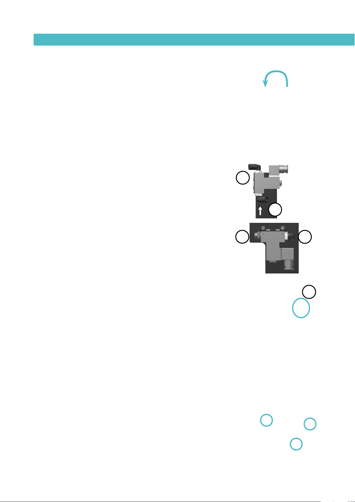
1. If it does not have a pressure regulator (PR): connect the air network of the
plant (6 bar max.) to the electrovalve inlet if the autoloader, which is marked
with an arrow (1), using a flexible tube with an exterior diameter of Ø10 mm. The
unit has a quick coupling to help you do so.
Connect the network air outlet (2) to the Y-coupling (3) located near the
adhesive suction port using a flexible tube with exterior diameter of Ø10 mm.
2
1
2. If it does have a pressure regulator (PR): connect the air network of the plant
(6 bar max.) to the electrovalve inlet of the autoloader, which is marked with the
number 1 (1), using a flexible tube with an exterior diameter of Ø10 mm. The
unit has a quick coupling to help you do so.
Connect the network air outlet, which is marked with number 2 (2), to the
Y-coupling (3) located near the adhesive suction port with a flexible tube with
exterior diameter of Ø10 mm.
Once connected, let the air pass through and check that it does not exceed 6
bars of pressure. Higher pressures would be an unnecessary expense and could
produce turbulence inside the melter basket and cause malfunctioning of the unit.
Warning: The air supply intake of the equipment and the air supply intake
of the autoloader must be different, because if you connected to a single air
supply intake the air supply to the piston might be affected when the adhesive
loader is in operation.
Suction tube connection
The suction tube should be connected to the swievel elbow of the vacuum
feeder, inserting it into the inside of the metallic mouth down to its bottom.
Place the swievel elbow to the most convenient position for installation,
depending on the location of the hot melt container.
2
1
3
Therefore:
• Loosen slightly the three fixing screws for the lid of the filter and set
the swievel elbow.
• Place the swievel elbow to the desired position, twisting it in the
required sense.
3-5
Page 24

FOCKE MELER GLUING SOLUTIONS
LOAD DETECTOR
CLOSED LID DETECTOR
INSTALLATION
• Tighten the three fixing screws to the position of the elbow and
prevent their movement.
Connecting control detectors
The vacuum feeder has two control sensors for the control of the operation of
the system.
The low level detector detects a low level of adhesive in the melter grid, in
order to activate the filling of adhesive and when it has reached the right level
to stop this filling. This sensor is located in the lid.
The ‘closed lid’ detector allows stop loading procedure when the lid is opened,
preventing the projection of adhesive outside. This detector is located at the
inlet of the fuser grill and the lid.
Both sensors are wired at the electrical cabinet.
Placing the suction tube
DEPRESSION
AIR INPUT
AIR EXHAUST INTERNAL
HOLES
To transfer the adhesive from the adhesive container to the hot melt
equipment, the suction tube should be inserted to the bottom of the container.
The four flaps that protects the entrance of the suction tube are designed to
keep the suction mouth open and without obstructions. It maintains a free
way for the suctioned adhesive.
The vibratory element (pneumatic) keeps the adhesive loose around the
entrance to facilitate its suction.
The aspiration element uses compressed air. By the help of the venturi effect,
a depression is created in it, that absorbs pearled and pallet adhesive and
drives it to the shell of the hot-melt system.
The Venturi effect, applied to the vacuum feeder, consists in a decrease of the
air pressure by an air flow inside the closed circuit while increasing the air
speed when passing through the narrowing of the entry mouth.
As the entry of aspiration is connected to this point, the aspired adhesive
stays in it and is transported to the hot-melt melter grid through the flexible
communication hose.
Hose and applicator connection
Micron MOD melters use standard Meler components. The entire range of
‘classic’, ‘compact’ and ‘manual’ hoses and applicators may be connected to
this equipment. Up to six hose-applicator outputs may be connected to this
equipment.
3-6
Warning: When connecting hose-applicator outputs, verify that the connected
power is not above the maximum allowable power for each output.
Micron MOD melters are equipped with a six outputs hydraulic distributors. Connect
the hoses to the distributor in order, following the numbering in the diagram.
Page 25

Caution:
• In order to identify each hose-applicator, electrically connect them to
the connector with the same number as the output they use.
• It is preferable to use couplings at a 90° angle to minimize the space
the hoses occupy. Using straight couplings usually results in curves
with very small radii that may damage the inside of the hose.
• Save the screw-on caps that are removed from the distributor in order
to connect a hose. They may be necessary in the future if a hose is
removed from its location.
MA-5094-E MICRON MOD ADHESIVE MELTER MANUALINSTALLATION
1
3
5
• Perform the electrical hose and applicator connections with the
equipment turned off. Failing to do so may result in electrical defects in
the connection and the appearance of alarm messages on the melter
display.
Parameter Programming
Once the melter and its components are installed, you will need to program
the operational parameters appropriate for the specific application that will be
performed.
Micron MOD melters simplify this task as much as possible, allowing the
operator to modify only those parameters that are necessarily variable for
each application.
Among the various parameters, it is necessary to program the set point
temperature values for each component connected and the value for
overheating warnings. There are two other parameters (weekly start-up and
shut-down programming and the standby temperature value) left to program
in advanced systems, although the factory default values are perfectly valid for
operational purposes.
Programming working temperatures
2
4
6
The melters/applicators leave the factory with the following set point
temperatures:
• 160 °C for the melter grid and the distributor
• 150 ºC for hoses and 160 ºC for appicators
The general process for modifying set up temperature values for any
component is described below.
1. Select the component for which you wish to modify the value with the
left-right arrow.
The corresponding LED will blink quickly.
3-7
Page 26

FOCKE MELER GLUING SOLUTIONS
INSTALLATION
2. Using the up-down arrow, select the desired value for the set point
temperature.
3. After ten seconds, the LED will stop blinking and the display will
change by default to the set point temperature, saving the changed
data.
-
-
ºC
-
10
160160
This simple process must be repeated for each one of the components installed on the melter/applicator.
Selecting the overheating value
1. Press the buttons with the clock symbol and the down arrow at the
same time to enter the special menu.
The choice of display units (ºC or ºF) will appear on the display.
2. Using the right arrow, we advance to the next screen where the
overheating symbol appears.
3. Select the desired value with the up-down arrow.
The value displayed corresponds to the increase in real temperature
over the set point temperature permitted without activating the alarm
message.
4. Use the right arrow to advance to the next screen.
3-8
5. Exit the special menu using the left arrow and the melter grid
temperatures will once again be displayed.
All the special menu values will be saved.
Keeping a component on display
By default, the main display shows the melter grid temperatures. However,
it is possible to display indefinitely the temperatures of any component for
analysis or tracking.
1. Select the component you wish to see permanently with the left-right
arrow.
The corresponding LED will blink rapidly.
Page 27

MA-5094-E MICRON MOD ADHESIVE MELTER MANUALINSTALLATION
2. Hold the arrow button down for two seconds, selecting the desired
component.
3. The display will now remain on the selected component, without
changing.
4. Simple press any left-right arrow button again to restore the default
display (melter grid).
External I/O connections
The melter/applicator’s input and output signals (I/O) allow it to communicate
with the main machine simply and directly.
There are two signals that may be used to communicate with the main
machine:
• Temperatures ok_an output from a non-voltage contact that
communicated to the main machine (or to a warning light beacon) that
all the system temperatures have reached 3° below their set point
value (and the delay time have finished) during start-up, or that their
real value is not 20°C below their set point value during operation.
• Output disabled_disabled input signal for each hose-applicator output
via a non-voltage contact. With a closed contact, the output remains
activated (output on); with an open contact, it is deactivated (output off).
Warning: Risk of electric shock. Carelessness may cause injuries or death.
Temperature ok
1. If only this signal will be connected, use a 0.5 mm2 two-wire cable.
Install an electrical wall bushing Pg13.5 on the equipment base plate
next to the electrical supply input.
2. Open the electric cabinet door as far as it will go. Run the signal cable (max.
Ø12.5 mm) through bushing Pg13 and attach it to the interior fitting, making
sure the cable reaches the indicated terminal.
3. Connect the terminals labelled as T OK.
4. Check that the cable is correctly connected and that its passage
through the electric cabinet presents no risk of jamming, being cut or
any other accidental damage.
Warning: It must be connected to 24 AC or DC voltage. If you connect this
signal to 230V load current cannot be less than 50mA.
3-9
Page 28

FOCKE MELER GLUING SOLUTIONS
INSTALLATION
Output disabled
1. If this is the only signal being connected, use a seven-wire cable no
smaller than 0.22 mm2.
Install an electrical wall bushing Pg13.5 on the equipment base plate
next to the electrical supply input.
2. Open the door to the electrical cabinet as far as possible. Thread the
power cord (max. Ø12.5mm) through the electrical wall bushing Pg13.5
and fasten it to the inside anchor, making sure that the cord reaches the
control card connector at the position where it will be installed (CN 5).
3. Remove the connector from the card and connect the two cable wires
to their corresponding connector terminals:
1 common (+) voltage output
2 input for disabled output 1
8 7 6 5 4 3 2 1
3 input for disabled output 2
4 input for disabled output 3
5 input for disabled output 4
6 input for disabled output 5
7 input for disabled output 6
8 without connection
4. Reconnect the card connector.
5. Make sure that the cable is well connected and that its path through
the electrical cabinet presents no risks of snagging, being cut or any
other accidental deterioration.
It is possible to select the channels that you want to control from the outside
using the small switches located above the connecter. Switches 1 through 6
control each of the channels, so that the switch in the ‘ON’ position means
heating from the equipment, without any external control.
When the switch is in the ‘OFF’ position, the corresponding channel does not
heat unless activated from the outside, through a non-voltage contact between
pin 1 (the common pin) and the pin that corresponds to the channel.
3-10
Page 29

MA-5094-E MICRON MOD ADHESIVE MELTER MANUALMELTER OPERATION
4. MELTER OPERATION
In this section we will introduce the method for using the melter. Although its
operation is very simple, it should not be used by untrained personnel.
Warning: Improper use may cause damage to the machine or injury and even
death to the person using it.
General information
There are three large groups of components with thermal control in a hotmelt installation: the fusion unit, the transport hoses and the applicators. All
of these are controlled from the front panel of the melter equipment.
The first large group is the melter grid-distributor group. Combined to form a
single unit, they have separate controls even though their set point values are
the same. Therefore, when you program a set point value for the melter grid,
for example 170°C, the distributor adopts this same value.
The second group is the hose group. They are identified on the front panel,
depending on the equipment model, by number, from No.1 to No.6 and by the
corresponding hose picture. Each one has its own set point value.
The third group is the applicators group. It is identified on the front panel,
depending on the equipment model, by number from No.1 to No.6 and by the
corresponding applicator picture. Each one has its own set point value.
The hose and applicators numbers are automatically assigned to the hose/
applicator channel they are connected to on the rear part of the melter.
4-1
Page 30

MELTER OPERATIONFOCKE MELER GLUING SOLUTIONS
Filling the adhesive
The adhesive loading system continuously supplies pellets to the equipment
based on the application requirements, so that only the adhesive that will be
used is melted. To do so, the 1.21 litre melter basket (for a density of 1 g/cm3)
is equipped with a low-level detector that warns you when the level of hot melt
drops.
Warning: Before refilling the melter grid, make sure that the adhesive is
the same type as that already in the melter grid. Mixing different types of
adhesives can cause damage to the melter/applicator equipment.
To carry out the filling of the adhesive:
1. The melter basket lid must be closed.
2. Make sure that the autoloader hose is connected.
3. Use the ON/OFF switch to switch on the melter.
4. If the level in the melter basket is high enough, autoloading will not be
activated. If the level detected is too low, after the level stabilisation
time has passed the electrovalve will activate and start loading. The
loading will stop when the disconnection delay time has passed.
Warning: Do not open the lid while the tank is refilling, otherwise the loading
will stop and it will be necessary restart the equipment.
Starting up the melter equipment
Before starting up the melter equipment, it is necessary to check to see if
the unit has been correctly installed and all its input/output and accessory
connections are correctly established.
It is also necessary to make sure that the equipment has been filled with
adhesive and that the operational parameters have been programmed.
To start:
1. Connect the melter’s switch.
4-2
If the control card was turned off the last time the machine was disconnected,
it will remain tuned off when the machine is started up again (time display).
If the control card was on the last time that the machine was disconnected, it
will turn on when the machine is started up again.
2. Press the ON/OFF button on the control card to turn it on, if it not
already activated.
Page 31

MA-5094-E MICRON MOD ADHESIVE MELTER MANUALMELTER OPERATION
By default, the set point and real temperature values shown are those
corresponding to the melter grid.
The melter grid heating control LED (green) will light up and the melter grid
will begin to heat.
One it has reached 3° below the programmed temperature (set point) of the
melter grid, a programmable delay timer starts until, guaranteeing fusion, the
pump receives permission to operate and the signal will be sent to the main
machine, indicated by the two corresponding (green) LEDs.
57 07
While the system is running the delay timer both LEDs remains blinking until
the programmed time value has been reached. If then, any other element has
not reached 3° below its temperature setting point, the LEDs turn off.
If the system is shut down, for any possible mode, when it is turning on the
delay timer only starts again if the melter grid temperature is 20° below
setting point.
3. Use the machine’s pressure gauge to make sure that the generated
pressure is adequate. Values below 0.5 bar may cause erratic pump
action.
160
Melter equipment displays
Micron MOD melters have two displays built into their control panel, with
three sets of 7 segments each for displaying the temperature values (set point
and real temperature), programmable parameters and alarms.
They are equipped with LED indicators to display the heating of each
component:
LED display Component heating Component status
constantly lit constant low temperature
blinking slowly as need (according to PID parameters) temperature near set point
blinking rapidly programming or display change in set point values
off not heating temperature reached
157
as well as the pump activations and the main machine connection signal.
They are also equipped with LEDs indicating equipment connection/
disconnection and standby function connection/disconnection:
LED display On/off Standby
constantly lit turned off unit function activated
blinking slowly
blinking rapidly
off unit in operation function deactivated
simultaneous intermittence from leds of
pump activation and main machine signal
deactivation programmed for the
current day
activation/deactivation
programming mode
timing in progress, once the melter grid has reached its set point
temperature
activation programmed for the
current day
activation/deactivation
programming mode
4-3
Page 32

MELTER OPERATIONFOCKE MELER GLUING SOLUTIONS
Displaying the temperature for each component
The temperature may be displayed for each component (melter grid, distributor
and each hose and applicator) by selecting the component with the cursor.
Press the left-right arrow until the desired component is displayed.
After 10 seconds, the display will return to the default component (the melter
grid).
If you wish to keep the component displayed permanently, press and hold the
left-right arrow for 2 seconds while selecting the chosen element.
The following is the display sequence:
distributor<—melter grid<—hose1<—applicator1<—…<—hose6<—applicator6
distributor—>melter grid—>hose1—>applicator1—>…—>hose6—>applicator6
To remove a component from permanent display, simply press either of the
left-right arrows.
Alarm displays
4-4
Micron MOD melter equipment tell the user when a malfunction has occurred
4Err
in the unit, sending warning messages that may be seen on the control panel
display.
Page 33

MA-5094-E MICRON MOD ADHESIVE MELTER MANUALMELTER OPERATION
Code Source Actions
Heating Pump Main machine signal
Err 0 melter grid broken sensor only melter grid off off off
Err 1 hose1 broken sensor only hose1 off off off
Err 2 applicator1 broken sensor only applicator1 off off off
Err 3 hose2 broken sensor only hose2 off off off
Err 4 applicator2 broken sensor only applicator2 off off off
Err 5 hose3 broken sensor only hose3 off off off
Err 6 applicator3 broken sensor only applicator3 off off off
Err 7 hose4 broken sensor only hose4 off off off
Err 8 applicator4 broken sensor only applicator4 off off off
Err 9 hose5 broken sensor only hose5 off off off
Err 10 applicator5 broken sensor only applicator5 off off off
Err 11 hose6 broken sensor only hose6 off off off
Err 12 applicator6 broken sensor only applicator 6 off off off
Err 13 distributor broken sensor only distributor off off off
Err 100 melter grid overheating all components off off off
Err 101 hose1 overheating all components off off off
Err 102 applicator1 overheating all components off off off
Err 103 hose2 overheating all components off off off
Err 104 applicator2 overheating all components off off off
Err 105 hose3 overheating all components off off off
Err 106 applicator3 overheating all components off off off
Err 107 hose4 overheating all components off off off
Err 108 applicator4 overheating all components off off off
Err 109 hose5 overheating all components off off off
Err 110 applicator5 overheating all components off off off
Err 111 hose6 overheating all components off off off
Err 112 applicator6 overheating all components off off off
Err 113 distributor overheating all components off off off
When an alarm appears, the control unit takes a series of steps to protect the
unit. Simply correct that malfunction and the control unit will reactivate the
equipment functions.
Standby function does not generate any alarm. If a temperature sensor is broken,
the system heats all the elements except the one where the failure is located.
In case of overheating the system cuts off inmediately the damaged element.
After three minutes if the failure continues all the system will be shut down.
After repairing the failure the system starts heating normally.
Operational pressure display and adjustment
The air pressure with which the pneumatic pump control device works with is
shown on the pressure gauge located on the base of the melter/applicator. The
pressure must be adjusted according to the application needs.
To do this, turn the regulator located on the front of the equipment next to the
pressure gauge counterclockwise as far as it will go. Activate the air supply to
pass and turn the pressure regulator clockwise.
n
---
4-5
Page 34

MELTER OPERATIONFOCKE MELER GLUING SOLUTIONS
Warning: Values below 0.5 bar may cause erratic pump action. Never surpass
6 bar of pressure. The multiplying effect of the pump elevates the hydraulic
pressure to dangerous levels for component operation.
Temperature adjustment
The melters/applicators leave the factory with the following set point
temperature values:
• 160 °C for the melter grid and distributor
• 150 ºC for the hoses and 160 ºC for applicators
• °C displayed
• Overheating value: 20°C
• Standby value: 40%
• Delay time: 10 min
off
40ºC
160160
• On/off and stanby programming: ON
• Low level detector: ON
The general process for adjusting the temperatures of each components is
described below.
1. Select the component whose value you wish to modify using the leftright arrow. The melter grid and the distributor have the same set point
value.
The corresponding LED will blink rapidly.
2. Select the desired set point temperature value with the up-down arrow.
Below 40°C the set point value displays ‘OFF’ canceling the heating of
that element.
3. After ten seconds, the LED will stop blinking and the display will show
the melter grid’s set point temperature value by default, saving the
modified data.
This simple procedure should be repeated for each of the components whose
set point temperature value you wish to modify.
4-6
Programming the applicator parameters
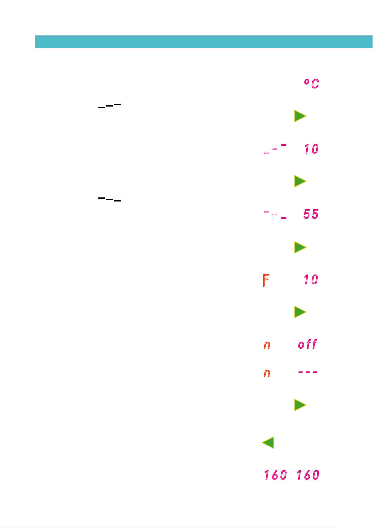
1. Simultaneously press the buttons with the clock symbol and the down
arrow to enter the special menu.
The choice of temperature display units (°C or °F) will appear on the
display.
Page 35
MA-5094-E MICRON MOD ADHESIVE MELTER MANUALMELTER OPERATION
2. Select the desired value using the up-down arrow.
3. Use the right arrow to move to the next display where the overheating
symbol appears.
4. Select the desired value (between 10 and 25) using the up-down arrow.
The value shown corresponds to the increase in real temperature
allowed over the set point temperature without activating the alarm
message.
5. Use the right arrow to go to the next display where the standby function
symbol appears.
-
-
ºC
-
10
6. Use the up-down arrow to select the desired value (between 25 and 55).
The value shown corresponds to the percent decrease in the real
temperature compared to the set point temperature that will occur
when this function is activated.
7. Use the right arrow to go to the next display where delay time value
appears.
8. Use the up-down arrow to select the desired value (between 0 and 60
min).
9. Use the right arrow to advance to the next screen, where the level
detector activation/deactivation is found.
10. The low level function on this equipment remains off at the control
board therefore t ‘n’ value will always be OFF.
-
ƒ
n
n
-
-
55
10
off
---
11. Use the right arrow to return to the initial parameter.
12. For any parameter, the left arrow may be used to exit the special menu
and display the melter grid temperatures once again.
To record any parameter, you must always move to the next parameter, using
the right arrow.
160160
4-7
Page 36

MELTER OPERATIONFOCKE MELER GLUING SOLUTIONS
Setting the clock
Micron MOD melters are equipped with a weekly programmable system
controlling equipment connection and disconnection and activating and
deactivating the standby function.
Before programming these functions, it is necessary to introduce into the
control unit data corresponding to the day and hour used to execute these
programs.
Programming the current day and hour
1. Press the button with the clock symbol.
0
2
A ‘0’ will appear on the display, indicating the program for current day
and hour information.
2. Press the button with the clock symbol once again.
On the left display, you will see the time with a dot, indicating that this
is the value that may be modified, while the minutes appear on the
02 .08
second display.
3. Use the up-down arrow to select the desired value.
4. Press the button with the clock symbol once again.
.02 08
Now the dot will appear on the right display.
5. Use the up-down arrow to select the desired value.
6. Press the button with the clock symbol once again.
A number appears, indicating the day of the week (1- Monday / 7-
Sunday).
4-8
0
7. Use the up-down arrow to select the desired value.
8. Press the button with the clock symbol once again.
The ‘0’ program appears once again.
9. Pressing either the left or the right arrow button will exit this program
and return to the melter grid temperature display.
Page 37

MA-5094-E MICRON MOD ADHESIVE MELTER MANUALMELTER OPERATION
Programming equipment activation/deactivation
You may program an activation and a deactivation time for every day of the
week, from Monday (1) to Sunday (7).
Time is expressed in 15 minute increments, so we cycle from 10.0 (10 hours
and 0 minutes) to 10.1 (10 hours and 15 minutes) to 10.2 (10 hours and 30
minutes) to 10.3 (10 hours and 45 minutes).
1. Press the button with the clock symbol
A ‘0’ will appear on the display, indicating the program for current day
and hour information.
2. Use the up-down arrow to select the value for the desired day of the
week, from Monday (1) to Sunday (7).
0
2
3. Press the button with the clock symbol once again.
Two times will appear, one in each display. The display on the left
shows the start time, while the display on the right shows the finish
time.
4. The blinking dot next to the start time indicates that this is the value
that may be modified. Use the up-down arrow to select the desired
value.
5. Press the button with the clock symbol once again.
The dot changes to the finish time.
6. Use the up-down arrow to select the desired value.
7. Press the button with the clock symbol once again.
The selected program will appear once again. Use the up-down arrow
to select other programs.
07.2
07.2
2
19.3
19.3
8. Pressing either the left or the right arrow button will exit this program
and return to the melter grid temperature display.
The green LED next to the ‘ON/OFF’ button will remain blinking as long as
there is an equipment disconnection time programmed for the current day.
160160
4-9
Page 38

MELTER OPERATIONFOCKE MELER GLUING SOLUTIONS
Disabling the equipment activation/deactivation program
It is possible to disable the equipment activation/deactivation programming
without canceling the daily programming. This way the programmed data is
saved, but the programming will have no effect on the equipment.
1. Press the button with the clock symbol.
A ‘0’ will appear on the display, indicating the program for current day
and hour information.
0
off
2. Use the up-down arrow to go past the selection for the last day of the
week (7).
The message ‘ON/OFF’ will appear on the display, depending on the
current status.
3. Press the button with the clock symbol once again.
The status will alternate each time you press the button.
160160
4. Pressing either the left or the right arrow button will exit this program
and return to the melter grid temperature display.
Programming the equipment’s standby function activation/deactivation
You may program an activation and a deactivation time for every day of the
week, from Monday (1) to Sunday (7).
4-10
0
1
2
Time is expressed in 15 minute increments, so we cycle from 10.0 (10 hours
and 0 minutes) to 10.1 (10 hours and 15 minutes) to 10.2 (10 hours and 30
minutes) to 10.3 (10 hours and 45 minutes).
1. Press the button with the clock symbol.
A ‘0’ will appear on the display, indicating the program for current day
and hour information.
2. Press the standby function button.
A ‘1’ will appear, indicating the first day in the standby function
programming.
[Since the current time and date are values common to both programs,
the value ‘0’ does not appear in this menu].
Page 39

MA-5094-E MICRON MOD ADHESIVE MELTER MANUALMELTER OPERATION
3. Use the up-down arrow to select the desired value for the day of the
week, Monday (1) to Sunday (7).
4. Press the button with the clock symbol once again.
Two times will appear, one in each display. The left display shows the
start time, while the right display shows the finish time.
5. The blinking dot next to the start time indicates that this is the time
that may be modified.
Use the up-down arrow to select the desired value.
6. Press the button with the clock symbol once again.
The dot changes to the finish time.
7. Use the up-down arrow to select the desired value.
8. Press the button with the clock symbol once again.
07.2
07.2
2
19.3
19.3
The selected program appears once again. You may use the up-down
arrow to select other programs.
9. Pressing either the left or the right arrow button will exit this program
and return to the melter grid temperature display.
The green LED next to the ‘maintenance’ button will remain blinking as long
as there is an equipment standby function activation time programmed for the
current day.
Disabling the equipment standby function programming
It is possible to disable the equipment standby function programming without
canceling the daily programming. This way the programmed data is saved,
but the programming will have no effect on the equipment.
1. Press the button with the clock symbol.
A ‘0’ will appear on the display, indicating the program for current day
and hour information.
160160
0
4-11
Page 40

1
off
MELTER OPERATIONFOCKE MELER GLUING SOLUTIONS
2. Press the standby function button.
A ‘1’ will appear, indicating the first day in the standby function
programming.
3. Use the up-down arrow to go past the selection for the last day of the
week (7).
The message ‘ON/OFF’ will appear on the display, depending on the
current status.
4. Press the button with the clock symbol once again.
The status will alternate each time you press the button.
160160
5. Pressing either the left or the right arrow button will exit this program
and return to the melter grid temperature display.
Special function buttons
The simplicity of programming Micron MOD melters reduces the use of the
special function buttons to only the standby function.
This manual function allows you to alternate between the operational mode
and the standby mode. Using the standby function during periods of melter/
applicator inactivity helps save energy and allows the heated elements
to return quickly to their set point temperatures once you return to the
operational mode.
When the standby function is activated, the set point temperature for all
the heated components is lowered to a certain value, according to the
programmed parameter (see ‘Programming melter/applicator equipment
parameters’). For example, if the melter grid set point temperature is 160 °C
and the standby temperature is programmed as 30 (30%), when you press the
standby function button, the melter grid set point temperature will drop to 112
°C (70% of 160 °C).
The three means for activating the standby function available with Micron MOD
melters have the following priority protocols:
1° manual standby function button.
4-12
2° standby function external signal.
Therefore, if the function is activated by any of the three means, it may always
be deactivated using the manual button. On the other hand, if it was activated
using the manual button, it may not be deactivated by either of the other two
means. The weekly programming may not deactivate a standby function that
has been activated by either of other two means.
The following criteria are suggested for standby function use:
Page 41

MA-5094-E MICRON MOD ADHESIVE MELTER MANUALMELTER OPERATION
- If the period of inactivity is less than 2 hours, allow the melter
applicator equipment to heat as normal.
- If the period of inactivity is more than 2 hours and less than 4 hours,
use the standby function.
- If the period of inactivity is over 4 hours, use one of the following two
options: turn off the equipment if you do not plan on using it for the
rest of the day or keep the standby function on if you plan on using the
equipment during that same day.
Start up and operation of the loader
The automatic pellet feeder operates fully automatically regardless of whether
the equipment temperature is OK; for example, if the equipment is running
it will begin to load whenever it detects that the level is too low, even if the
equipment temperature is not OK. The normal loading process is as follows,
and proceeds according to the scheme below:
1. Push the switch on the front of the control panel to switch on the
equipment (see figure).
2. If the melter basket level is high enough, autoloading will not be
activated and the warning light and the buzzer will both be OFF.
3. If it detects that the level is too low after the level stabilisation time has
passed, the electrovalve will be activated and the warning light will go
on, at which point loading will begin.
4. When it detects that the level is high enough after the disconnection
delay time has passed, loading will stop, and the electrovalve and the
warning light will both switch off.
Low level detection Launching the feeder
Stopping the feeder
System refilled
Detection of the correct level
Start of the over-level timing
4-13
Page 42

MELTER OPERATIONFOCKE MELER GLUING SOLUTIONS
Loader standby function
If the equipment temperature is OK and the “T.ST change to standby status”
time has passed, the outlet to put the equipment into “STBY standby status”
will be activated. With this status, the warning light will flash slowly and
autoloading will not occur. There are three ways to reset this status on the
equipment:
- If you push the loader “RESET” button, the programmable relay output
for the standby signal will open and the equipment will go into ON
status. Autoloading will be activated and the warning light will switch
OFF.
- If you push the standby button on the front panel, the equipment will
go into ON status; you also have to push the “RESET” button on the
adhesive loader. Loading will be activated and the warning light will
switch OFF.
- If you push the standby button on the front panel, the equipment will go
into ON status and when its temperature is OK the programmable relay
will detect it and reset the loader. Autoloading will be reactivated and
the warning light will switch OFF.
If you want to disable the automatic pellet feeder, push and hold the OFF
button for 3 seconds. The warning light will start to flash slowly. If you want to
activate loading, push the lit “RESET” button and loading will be reactivated.
OFF mode resets all existing alarms (if it goes into OFF mode with the open lid
alarm activated, when loading is activated and if the lid is still open it will wait
the programmed time to activate the open lid alarm).
Single-colour or two-colour warning light
If the equipment has the warning light optional feature, the colourless warning
light statuses are as follows:
1. OFF: the equipment’s level is high enough.
2. Steady on: the equipment is loading (EV= ON)
3. Very slow flashing: load blocked status
4. Slow flashing: equipment on standby.
5. Fast flashing: error status.
4-14
If it also has a green warning light, this signals that the equipment
temperature is OK (lit) or not (off).
Page 43

MA-5094-E MICRON MOD ADHESIVE MELTER MANUALMELTER OPERATION
Level sensor adjustments
Sensitivity adjustment
The adjustable sensitivity of the sensor, depending on the material used and
the hysteresis admitted to the operation of the vacuum feeder is factory presetted and therefore it is NOT necessary to change. In most cases the factory
setting is perfectly valid to use the vacuum feeder.
If it is necessary to correct the adjustment contact the Technical Services
Meler or Area Representative.
Level stabilisation time
The level stabilisation time is the time that passes between when the
equipment detects that the level is too low and when the electrovalve is
activated (EV=ON) to load adhesive. This parameter is not programmable
from the timer menu; it is a set time that may only be modified by editing the
program. The default time is 2 seconds.
Programmable times using the timer
Disconnection delay time
The extra time that the loader operates after the correct level has been
reached is called the disconnection delay time. The screen shows ‘T.EV 00:00s’
and you can program the first digits in seconds and the digits after the “:” in
hundredths of a second.
Operating alarms
1. Load error alarm
Each time the load sensor detects low adhesive a safety timer is connected
(Default 90 seconds). That controls of time lap the device is charging. This
timer is resetted when the sensor detects correct adhesive level.
In case that within the scheduled time (90 seg) the level sensor has not
detected the correct level, the system assumes the existence of a failure in the
loading circuit and connects the warning signs:
- Beep buzzer.
- Amber light blinking signal in the control panel.
Both signals remain activated while they are not restarted.
Pressing the black button the acoustic signal can be overridden.
4-15
Page 44

MELTER OPERATIONFOCKE MELER GLUING SOLUTIONS
Pressing the amber light button the system will be resetted. The security time
will begin to count again.
You just have to press the reset button after having corrected the existing
failures:
- Obstruction of aspiration hose.
- Mismatch of the sensitivity of the level sensor .
- Empty adhesive container.
2. Open lid alarm
When you open the lid of the hot-melt melter grid, the magnetic sensor gives
the signal to the programmable relay to interrupt the loading procedure.
Closing the lid, after 10 sec. the loading procedure restarts.
If keep the lid open longer than the time programmed into the parameter
‘ALARM’, the alarm is triggered and connects the warning signs:
- Beep buzzer.
- Amber light blinking signal in the control panel.
Both signals remain activated while you do not act on them.
Pressing the black button the acoustic signal stopps.
Pressing the amber light reset button the system restarts except if the lid is
still open.
When either of these alarms occurs, the loading cycle stops if it had not yet
begun, or does not begin if the equipment is in standby. The electrovalve
output is deactivated, the warning light flashes quickly and the buzzer starts.
The screen shows ‘T.AL 00:00m’ and you can program the first digits in
minutes and the digits after the “:” in seconds.
Change to standby time
Once the equipment temperature is OK and the adhesive level is correct,
as soon as loading is finished a timer begins in the program; once the
programmed “T.ST” time has been reached an outlet contact is activated that
puts the melter into “STBY change to standby” status. If while the timer is
counting down the equipment level drops or the temperature is not OK, the
timer will stop. Then, when the equipment returns to OK temperature and
correct adhesive level the timer will reset and begin to count down again. The
screen shows ‘T.ST 00:00h’ and you can program the first digits in hours and
the digits after the “:” in minutes.
4-16
Setting programmable times using the timer
Inside the electric cabinet there is a programmable relay to set the
disconnection delay time of the electrovalve (T.EV), the error alarm (T.AL) and
the standby (T.ST) for periods of inactivity.
Page 45

MA-5094-E MICRON MOD ADHESIVE MELTER MANUALMELTER OPERATION
To open the electric cabinet, loosen the screw that holds in place the door to
the electric cabinet casing on the left side, and slide it out.
The following is the procedure to change the times for each element:
1. Press the ESC key for several seconds until the cursor appears under
the first digit of T.EV.
2. Use the left-right arrows to move to the value you want to change.
Click OK and you will see the digit in negative (light digit over a dark
background).
3. Change the T.ST value with the up-down arrows.
4. Use the left-right keys to move to a different digit.
5. Once finished, click the OK key to validate the changes and exit editing
mode by pushing ESC. The change is now in operation.
Thermostat operation
The thermostat protects the equipment from uncontrolled rises in
temperature. When the overheating value is exceeded, the thermostat is
triggered and the button breaks contact. The equipment then shuts off and you
must reset it for it to work again; do this by sliding open the electric cabinet
and lifting the insulating blanket off the melting basket. Once the thermostat
is exposed, push the button shown in the figure to reset it.
Turning off the melter equipment
If you need to disconnect the melter equipment:
1. Turn off the machine switch on the door of the electrical cabinet next to
the pressure regulator.
The depressurization valve frees pressure from the hydraulic circuit,
returning the adhesive to the melter grid.
2. Disconnect the pneumatic power to the applicators and the electrical
power to the control unit programmer, if there is one.
4-17
Page 46

MELTER OPERATIONFOCKE MELER GLUING SOLUTIONS
This page is intentionally left blank.
4-18
Page 47

MA-5094-E MICRON MOD ADHESIVE MELTER MANUALMAINTENANCE
5. MAINTENANCE
Warning: The melter equipment is equipped with current technology, but
has certain foreseeable risks. Therefore, only allow qualified personnel with
enough training and experience to operate install or repair this equipment.
The following table briefly summarizes the indications for adequate melter
equipment maintenance. Always read the corresponding section carefully.
Operation Frequency Refer to
External cleaning Daily Equipment cleaning
System depressurization
Remove electrical cabinet
Pneumatic system
Filter cleaning or changing
Emptying and cleaning the melter
grid
Check thermostat operating - Check in continuous work Thermostat maintenance
Load sensor
Suction hose Weekly Aspiration hose inspection
Exhaust air filter Weekly Automatic feeder filter maintenance
Pneumatic vibrator Weekly Control of pneumatic vibrator
Equipment change - Equipment change or repair Remove the equipment from its base
Before performing maintenance tasks
and repairing the hydraulic system
Before performing pneumatic unit or
pump shaft maintenance
- Daily: pressure control
- Weekly: leakage inspection
- As needed (once a year minimum)
- With each adhesive change
- When burnt adhesive is present
- With each adhesive change
- Daily: load control
- Weekly: cleaning
System depressurisation
Access to pneumatic unit
Access to pneumatic unit
Pump filter maintenance
Cleaning the melter grid
Control of load sensor
If the equipment does not work or works incorrectly, you may refe r to the next
chapter ‘6. Quick problem solving’.
Equipment cleaning
To continue to take advantage of the melter’s benefits and to ensure the
perfect mobility of its components, it is necessary to keep all its parts clean,
especially the ventilation grate on the upper part of the machine.
Warning: Risk of electric shock. Carelessness may result in injury or death.
Clean the exterior using a cloth moistened with water. Do not use flammable
liquids or solvents.
5-1
Page 48

To carry out external cleaning:
• Use cleaning products compatible with polyamide materials.
• Apply the cleaning product with a soft cloth.
• Do not use sharp tools or scrapers with sharp edges.
Removing and changing exterior panels:
1. Turn off the melter.
MAINTENANCEFOCKE MELER GLUING SOLUTIONS
D
E
A
C
C
B
D
2. Disconnect the compressed air from the machine intake.
3. To remove the casing from the machine, first you have to separate the
electrical cabinet from the melter grid. To do this, slacken the 1/4 turn
screw as indicated (A) and slide it along the guides.
3. To remove the electrical cabinet door, open the door by turning the 1/4
turn screw as indicated (B), lift the door, turn it and remove the screws
(C).
4. To remove the electrical cabinet casing, slacken the screws (D) that
hold it to the base of the machine and the screws (E) that hold it to the
structure of the electrical cabinet.
5. To remove the melter grid casing, remove screws (F) and (G) that hold
this casing to the base of the equipment. The lid and the casing are
removed from the melter grid at the same time.
6. The melter grid lid is removed once the melter grid casing has been
dismantled. It is simply a matter of sliding the shafts at the ends along
the grooves in the casing. (See diagram).
5-2
G
F
7. To assemble the casing, follow the instructions in reverse order.
System depressurisation
Micron MOD melters are equipped with a safety valve that allows you to
depressurize the system whenever the equipment is pneumatically or
electrically disconnected.
Page 49

MA-5094-E MICRON MOD ADHESIVE MELTER MANUALMAINTENANCE
Before disconnecting any hydraulic component or opening any distributor
output, it is necessary to follow these steps:
1. Turn off the machine switch on the door of the electrical cabinet next to
the pressure regulator.
The depressurization valve releases the pressure from the hydraulic
circuit, returning the adhesive to the melter grid.
2. Purge all applicators that have been used either manually or with the
corresponding program command.
Access to pneumatic unit
To access the unit for more exhaustive machine maintenance, it will be
necessary to remove the electrical cabinet from its place so it can be handled
more comfortably and accessibly. To do this, slacken the 1/4 turn screw that
keeps the electrical cabinet in position (screw A) and slide it along the guides
indicated (B).
To carry out this operation it is not necessary to open the electrical cabinet
door.
Pneumatic circuit
Control regularily the pressure feeding circuit. Very low pressures do not allow
proper loading of the adhesive. Very high pressures can produce splash of
melten adhesive in the melter grid of the melting unit and even cooling of the
hot melt.
Monitor periodically if there is any leak in the pneumatic circuit. In addition to
being a useless expense resulting in loss of pressure and thus malfunction of
the system load.
Pump filter maintenance
The adhesive flows from the inside to the outside of the filter, with impurities
being trapped inside it.
The drain valve is included in the filter cap.
When the filter is removed from its housing, all the impurities remain trapped
inside, and the inside of the distributor stays perfectly clean. The filter may be
cleaned or replaced directly with a new one.
No rule exists for determining when to change the filter. Several factors
influence this decision:
• The type and purity of the adhesives used.
• The adhesive work temperatures.
• Adhesive consumption in relation to the time it spends in the melter grid.
purge zone
5-3
Page 50

MAINTENANCEFOCKE MELER GLUING SOLUTIONS
• Changes in the type of adhesive used.
In any case, we recommend checking and cleaning the filter at least every
1000 hours of operation (melter/applicator equipment turned on).
Warning: Always use protective gloves and goggles. Risk of burns.
To change the filter, it should be borne in mind that the filter and purge valve
are the same assembly:
1. Depressurise the system.
2. To remove the whole filter, unscrew the assembly’s hexagonal plug
using a 15mm socket driver and remove it.
3. Depending on the amount of dirt inside the cartridge, clean it or throw
it away, following the applicable waste regulations.
4. Replace the joints if they are damaged.
5. Screw the assembly up again, clockwise.
6. Put the assembly back inside the distributor and tighten the screws.
7. Continue to work as normal.
Cleaning the melter grid
The hot-melt melter grid must be cleaned on occasion to maintain its fusion
and anti-adherence properties. The melter grid is covered on the inside with
PTFE.
Furthermore, when adhesives are mixed, reactions may occur between them,
causing a degeneration and thus problems in unloading in the direction of the
pump.
Therefore, it is recommended to clean the deposit every time that:
• A change is made to a different type of hot-melt.
• Too much burnt material is generated in its interior.
5-4
Cleaning burnt adhesive
1. Use up as much of the adhesive as possible.
2. Clean the adhesive remains and burnt material inside the melter grid.
Do not use sharp objects that might damage the inside coating.
Page 51

Warning: Use appropriate protective equipment for high temperatures.
3. Add cleaning adhesive, and pump it through the system (hoses and
applicators) at list 1,5 liters aproximately.
4. Add the appropriate type and quantity of adhesive and wait for it to
melt.
5. Remove the filter cartridge and clean it, if necessary (see the section
‘Pump filter maintenance’).
6. Reassemble the filter without the cartridge.
MA-5094-E MICRON MOD ADHESIVE MELTER MANUALMAINTENANCE
7. Pump a minimum of one melter grid through the distributor output
marked number 1.
8. Remove the filter and attach it to the corresponding cartridge. Reinstall
it in the distributor.
9. Refill the melter grid with adhesive and continue working as usual.
Warning: Whenever you handle the filter or any other element subject to
pressure, you must always perform a system depressurization first (see the
corresponding section).
If you want to remove the top of the melter grid for a more thorough cleaning,
you can turn it off easily using the connector designated for separate it from
the equipment.
Safety Thermostat
If there is an error in the resettable thermostat. Dismantle the tank casing
with the cover and slide the electrical cabinet along. When you can see the
thermostat, press the button indicated to reset it.
1
Control of the load sensor
It is necessary to control if the load sensor is working properly and that it
allows you to maintain the desired levels.
A low load will cause a decline in the level and the possibility of not having
the amount of necessary hot-melt adhesive. By contrast, an overload can
cause the overfilling of the melter grid with subsequent sealing of the loading
mouth.
The load sensor should remain clean of charred adhesive that may affect the
proper level detection.
5-5
Page 52

MAINTENANCEFOCKE MELER GLUING SOLUTIONS
Inspection of the aspiration hose
Monitor that the aspiration tube is not obtured with sticked glue pallets or
perls. This tube should be perfectly free of any glue plugs that impedes the
smooth transfer of the adhesive from container to the melter grid of the
melting unit.
The tube is mostly transparent to facilitate visual inspection of the same.
Automatic feeder filter maintenance
Periodically review the state of the filter located inside the discharge zone.
Blow compressed air impurities that may have acceded to.
This filter avoids dust particles or glue pallets itself being spilled outside with
the exhaust air. If it arrived to be plugged the system might not work properly.
To clean, unscrew the three screws of the rotary elbow lid and extract the filter.
Control of pneumatic vibrator
Reviewing the correct operation of the pneumatic vibrator located in the
suction mouth. Ensures that it vibrates and its vibration is adequate.
Clean up the exhaust silencer of impurities and adhesive dust.
Remove the equipment from its base
For more thorough equipment maintenance, it is necessary to remove it from
its present location to be able to perform operations more comfortably and
with greater accessibility.
To do this, the equipment should be removed from its base following these
indications:
1. Turn off the machine switch on the door of the electrical cabinet next to
the pressure regulator.
2. Depressurise the system.
3. Disconnect the hoses connected to the distributor outputs both
electrically and hydraulically.
5-6
4. Disconnect the input power supply and ground connection.
5. Raise the machine to extract it from the base.
Page 53

6. TROUBLESHOOTING
This chapter shows basic help for solving simple problems without
intervention from Meler technical personnel.
It is very important to respect the security instructions in this manual at all
times. Failure to do so may result in personal injury and/or damage to the
machine or to the rest of the installation.
Warning: The melter/applicator equipment is equipped with current
technology, but with certain foreseeable risks. Therefore, only allow
appropriate personnel with enough training and experience to use, install or
repair this equipment.
Each observed problem corresponds to a chapter section. There are four
different columns in each one:
MA-5078-E MICRON ADHESIVE MELTER MANUALTROUBLESHOOTING
• Possible causes
• Verification to be performed
• Useful observations
• Actions
The system is simple. Locate the chapter section that corresponds to the
observed problem. Starting from the column on the left, follow vertically the
causes. Once the cause is found check, the action is performed taking into
account the comments and once the error checked carried out in each case
corrective action.
If you do not reach the cause follow to the next problem.
If you are unable to solve the problem with the help provided in this chapter,
contact your Area Technical Service Center or Meler headquarter directly.
6-1
Page 54

Melter
The unit does not turn on
Causes Checking Comments Actions
Check voltage between phases
Equipment power
supply malfunction.
Switch malfunction. Check continuity in switch (1S2)
Power board
malfunction.
Control board fuse
damaged.
Control board
malfunction.
Thermostat failure.
Thermostat failure.
Thermostat failure.
and neutrals in the main
terminal. Check voltage in CN4
connector (power board).
Check voltage in CN8 connector.
Verify continuity in fuse (F1).
Check voltage in CN9 connector.
Check continuity at the thermostat
with the switch turned ON.
The thermostat triggers when
reset.
The thermostat triggers when
reset
Voltages will vary depending on
power supply.
If continuity in CN7 connector,
switch is OK.
Bypass CN8 pins. If 230V, the
board is correct.
Check first 230V is supplied to
the control board (CN8)
Fuse works and 230V arrive to
control board
If there is no continuity reset the
thermostat by pushing the button.
There is continuity but the
temperature has not dropped
enough.
After waiting a bit the
temperature does not drop.
Check wiring.
Check net power supply.
Change electric supply
cable.
Change switch.
Change power board.
Change fuse.
Change control board.
Replace the thermostat if
there is still no continuity.
Wait to reset it again and
check
Check the resistors and
melter grid probe.
TROUBLESHOOTINGFOCKE MELER GLUING SOLUTIONS
Equipment shortcircuit malfunction
Causes Checking Comments Actions
If the melter grid is
Shortcircuit in melter
grid.
Shortcircuit in manifold.
Hose-gun shorcircuit
(1-6 output).
Disconnect CN6 connector
from the power board.
Disconnect CN6 connector
from the power board
Disconnect the hoseconnectors one by one until
the unit turns on.
shortcircuited, the system
will turn on. Reconnect CN6
and release the wires from
the melter grid terminal strip.
If the distributor is
shortcircuited, the system
will turn on. Reconnect CN6
and release the wires from
the manifold terminal strip.
Later, it will have to be
found out if the shortcircuit
is in the hose or in the gun.
Check wiring, some cables
might be bypassed.
Change melter grid.
Check wiring, some cables
might be bypassed, broken...
Change heating elements of the
distributor
Change hose or gun.
6-2
Page 55

MA-5078-E MICRON ADHESIVE MELTER MANUALTROUBLESHOOTING
The equipment does not automatically go into standby
Causes Checking Comments Actions
Erroneous
programming of the
Logo relay.
Failure in the power
supply.
Temperature OK
contact damaged.
Damaged relay.
Logo programmable
relay damaged.
External standby
connector damaged.
Check the standby time on the
Logo screen (T.ST).
Check that there are 24 volts
of direct current at the power
supply outlet.
Check the continuity of the
contact (contact 3-4) with the
equipment with temperature OK.
Measure the voltage at relay
(A1-A2) with the temperature OK.
Then check the continuity of the
normally open contact.
With temperature OK, check the
continuity at the Logo Q4 outlet.
Verify the continuity of the
External standby connector on
the control board.
Open the electric cabinet to
access the Logo.
If there are not 24 volts, the
source is damaged.
Remove the green connector to
check the continuity (CN1 power
board). If there is no continuity
the contact is damaged.
Remove the cables to check the
contact continuity. If there is
continuity the relay is OK.
Verify the continuity without
the output cables. If there is
no continuity the Logo is not
working correctly.
Remove the green connector
to check the continuity (CN4
control board). Connect the
two terminals using something
metal. If it functions properly the
equipment will go into Standby.
Change the
programming to suit
production.
Change the power
supply.
Replace the T.ST power
board.
Replace the relay.
Replace the Logo
programmable relay.
Replace the T.ST control
board.
The equipment does not come out of standby into heating
Causes Verification action Observations Corrective action
Temperature OK
contact damaged.
External standby
connector damaged.
Logo programmable
relay damaged.
The equipment does not load adhesive
Causes Verification action Observations Corrective action
Lack of adhesive in the
loading canister.
There is no air
pressure.
Loading tube
obstructed.
Remove the green temperature
OK connector on the power board
(CN1).
Remove the green External
standby connector on the control
board (CN4).
Remove the green External
standby connector on the control
board (CN4).
Check the adhesive in the
canister.
Check that air is reaching the
inlet electrovalve.
Remove the tube and look inside
it.
If when you remove the
connector the equipment goes
back into heating mode the
connector is damaged.
If when you remove the
connector the equipment stays
in Standby mode the connector
is damaged.
If when you remove the
connector the equipment
goes into Standby mode
the Programmable relay is
damaged.
--
Check if there are 6 bars of
pressure.
--
Replace the power
board.
Replace the control
board.
Replace the
programmable relay.
Fill the canister with
pellets.
Inject air into the
system.
Replace the tube or
clean it if possible.
6-3
Page 56

TROUBLESHOOTINGFOCKE MELER GLUING SOLUTIONS
Causes Verification action Observations Corrective action
With the equipment temperature
Temperature OK
contact damaged.
Load electrovalve
damaged.
Magnetic detector
damaged.
OK, remove the CN1 green
connector from the power board
and check the continuity.
Manual operation of the
electrovalve.
With the lid closed measure the
continuity between input l2 and
24 volts.
If there is continuity the
connector is OK.
If the adhesive does not load
by manually operating the
electrovalve, it is damaged.
If the sensor shows continuity
with the lid closed, it is OK.
Replace the power
board.
Replace the
electrovalve.
Replace the magnetic
sensor.
Melter grid
The melter grid does not heat
Causes Checking Comments Actions
Equipment power
supply malfunction.
Ribbon cable
malfunction.
Melter grid fuse
blown.
Power board
damaged.
Power supply wire
to the melter grid
damaged.
Thermostat damaged. Check continuity in B2.
Heating element
shortcircuited or
blown.
Check voltage between phases
and neutrals.Check voltage in
CN4 connector (power board).
Check ribbon cable (CN11).
Check fuse continuity (F01).
Check CN6 connector voltage
(pins 2 and 4).
Check CN6 connector voltage
(pins 2 and 4) and in the melter
grid terminal strip.
Check voltage in the terminal
strip.
Voltages will vary depending on
power supply.
Check the connections between
the cable and the board.
Release the fuse to check it out
with the system turned off.
Correct if voltage is around
230V and DL2 is on.
If connector voltage is around
230V and the cercamic terminal
strip does not, the wire is
damaged.
There must be voltage in the
ceramic terminal strip.
Correct if voltage equals to
230V.
Check wiring.
Check electrical net.
Change electric supply
cable.
Change ribbon cable.
Change fuse.
Check wiring, it might
be wrong positioned.
Change board.
Check connections
to the connector and
terminal strip.
Change wire.
Change thermostat.
Change melter grid.
The melter grid does not stop heating
Causes Checking Comments Actions
Power board
malfunction.
Control board
malfunction.
Check power board (pins 2 and 4
in CN6).
Check control board. LED indicator (DL2) remains on. Change control board.
LED indicator (DL2) remains
off.
6-4
Change power board.
Page 57
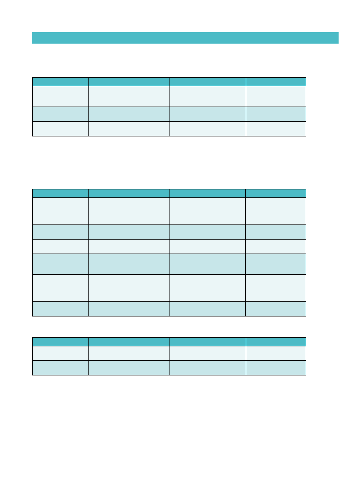
MA-5078-E MICRON ADHESIVE MELTER MANUALTROUBLESHOOTING
Temperature fluctuations in the melter grid
Causes Checking Comments Actions
Temperature sensor
malfunction.
Sensor wrong
positioned.
Sensor board
malfunction.
Check the sensor resistance
(Pt-100 or Ni-120) with polimeter.
Check the sensor position inside
its housing.
Last failure option.
Check the CN1 connector
(sensor board) and the two
upper wires status.
Sensor must be introduced to
the bottom.
Check first sensors,
connections and wirings.
Change connector.
Change sensor.
Introduce sensor to the
bottom.
Change sensor board.
Manifold
The manifold does not heat
Causes Checking Comments Actions
Check wiring.
Check net power supply.
Change electric supply
cable.
Change ribbon cable.
Change fuse.
Check connector wiring,
position.
Change board.
Check connections
between the connector
and the terminal strip.
Change wire.
Change heating
elements.
Equipment power
supply malfunction.
Ribbon cable
malfunction.
Manifold fuse blown.
Power board
damaged.
Power supply wire
to the melter grid
damaged.
Fuse shortcircuited or
blown.
Check voltage between phases
and neutrals.Check voltage in
CN4 connector.
Check ribbon cable (CN11).
Check fuse continuity (F02 in
CN6).
Check voltage in the CN6
connector (pins 1 and 3).
Check voltage in the CN6
connector (pins 1 and 3) and in
the manifold terminal strip.
Check voltage in the terminal
strip.
Voltages will vary depending on
power supply.
Check the connections between
the cable and the board.
Release the fuse to check it out
with the system turned off.
Correct if voltage is around
230V and DL1 is on.
If voltage around 230V in
the connector, but not in the
terminal strip, the wire is
damaged.
Voltage should be around 230V.
The manifold does not stop heating
Causes Checking Comments Actions
Power board
malfunction.
Control board
malfunction.
Check the power board.
Check the control board. LED indicator (DL1) remains on. Change control board.
LED indicator (DL1) remains
off.
Change power board.
6-5
Page 58

TROUBLESHOOTINGFOCKE MELER GLUING SOLUTIONS
Temperature fluctuations in the manifold
Causes Checking Comments Actions
Temperature sensor
malfunction.
Sensor wrong
positioned.
Sensor board
malfunction.
Check the sensor resistance (Pt100 or Ni-120) with polimeter.
Check the sensor position
inside its housing.
Last failure option.
Check CN1 connector (sensor
board) and the two bottom wires
status.
Sensor must be introduced to the
bottom.
Check first sensors, connections
and wirings.
Change connector.
Change sensor.
Introduce sensor to
the bottom.
Change sensor board.
Pump
The pump does not pump
Causes Checking Comments Actions
No adhesive in the
melter grid.
Melter grid filter dirty.
Shaft malfunction.
Intake valve
malfunction.
Depressurization valve
malfunction.
Pump blocked. Try to manually move the shaft. Try to move it when shaft warm.
Check the hot-melt level in the
melter grid.
Check the filter and clean the
bottom of the melter grid.
Check if adhesive returns
through the FOI o-rings to the
melter grid. (system under
pressure).
Check if there are bubbles at
the valve area due to adhesive
return (system under pressure).
Check if adhesive returns
through the valve (system under
pressure).
Pump shaft moves fast in both
directions.
Bottom of the melter grid dirt
impregnated.
Fast pumping but without having a
continuous adhesive output.
Fast pumping in one direction
and without having a continuous
adhesive output.
Fast pumping in one direction
and without having a continuous
adhesive output.
Pneumatic unit
Pneumatic unit malfunction
Refill melter grid with
adhesive.
Change or clean filter.
Change shaft.
Change intake valve.
Change
depressurization
valve.
Clean or change
pump.
Causes Checking Comments Actions
No air pressure.
Intake solenoid valve
damaged.
Power board
malfunction.
Differential valve.
Check the pressure in the
regulator and net pressure.
Check solenoid valve and
voltage in the board (CN2) is
230V (power board).
Check if voltage in CN2 is 230V. If voltage, card is OK. Change power board.
Replace the valve and try the
pneumatic unit again.
If no pressure, the manometer will
show zero bars.
Check the equipment manually to
verify if it works (position 1).
The pneumatic unit does not move
from one side to the other.
6-6
Change pressure
regulator.
Change solenoid
valve.
Change differential
valve.
Page 59

MA-5078-E MICRON ADHESIVE MELTER MANUALTROUBLESHOOTING
Causes Checking Comments Actions
Air leakage. Put the pressure at 6 bars. Any element may leak
Complete pneumatic
unit.
Release the pneumatic unit. The pneumatic unit does not move.
Change fittings,
valves...
Change complete
pneumatic unit.
Adhesive leaks
Causes Checking Comments Actions
Pump shaft leaks
Relief valve leaks.
Manifold plug leaks.
Leaks between pump
and melter grid.
Hose fitting leaks.
Put the system (melter + hose +
gun) under pressure.
Put the system (melter + hose +
gun) under pressure.
Put the system (melter + hose +
gun) under pressure.
Put the system (melter + hose +
gun) under pressure.
Put the system (melter + hose +
gun) under pressure.
Plain bearings worn.
The manifold hole is full of
adhesive.
Dripping below the manifold.
Dripping at the pump.
Dripping by external part of the
manifold.
Change shaft
completely.
Change relief valve.
Change plug o-ring
and retighten it. Thread
might be damaged.
Change o-rings in both
parts.
Change fitting o-ring
and retighten it.
Thread might be
damaged.
6-7
Page 60
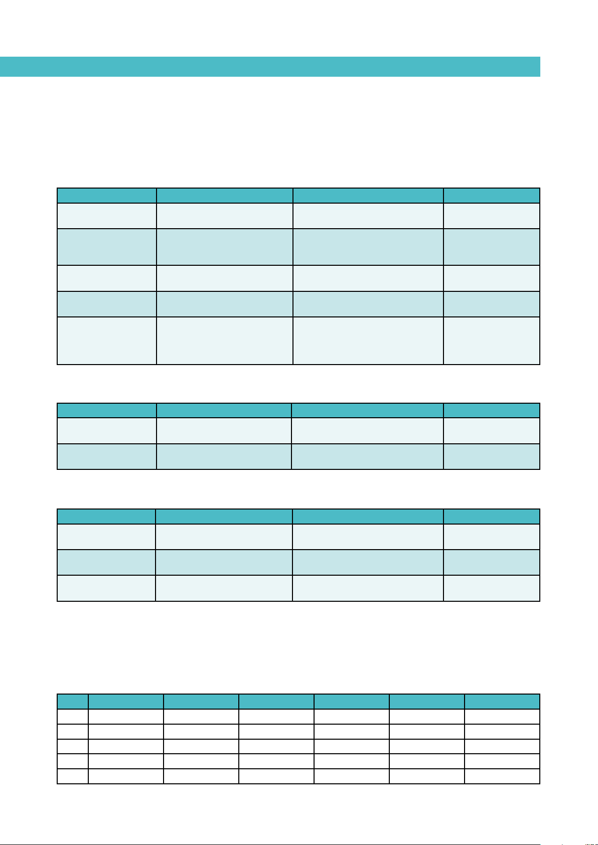
Hose
Hose does not heat
Causes Checking Comments Actions
Hose damaged.
Pins and wiring
damaged.
Ribbon cable wrong
placed.
Power board fuse
damaged.
Power board
damaged.
Replace the hose by another
one that works.
Check voltage between board
and hose-output connector
(with the hose plugged).
Observe ribbon cable
connection.
Verify fuse continuity.
( 2 )
Check voltage at the board
output (with the hose plugged).
Change hose channel. Change hose.
CN* connector (black wire-neutral
and blue wire-hose M*)
( 1 )
Ribbon cable correct if red LED
light on (DL15).
Check continuity with the unit
turned off.
Change connectors.
Put ribbon cable
correctly.
Change fuse.
CN* board connector (black wireneutral and blue wire-hose M*).
Fuse shows continuity. DL* LED
light remains on.
( 3 )
Change power board.
TROUBLESHOOTINGFOCKE MELER GLUING SOLUTIONS
Hose does not stop heating
Causes Checking Comments Actions
Power board
damaged.
Control board
damaged.
Check power board.
--
DL* LED green indicator is
continuously off.
DL* LED green indicator is
continuously on.
( 4 )
( 4 )
Change power board.
Change control board.
Temperature fluctuations in hose
Causes Checking Comments Actions
Hose temperature
sensor malfunction.
Sensor wiring.
Sensor board
malfunction.
Replace the hose by another
one that works.
Check sensor board and hose
connector.
Last failure option.
Change hose channel. Change hose.
CN* sensor board connector (black
and green wire).
( 5 )
Check first sensors, connections
and wirings.
Change connector.
Change the sensor
board.
Note Hose 1 Hose 2 Hose 3 Hose 4 Hose 5 Hose 6
(1) CN9 / M1 CN9 / M2 CN10 / M3 CN10 / M4 CN11 / M5 CN11 / M6
(2) F04 F05 F06 F07 F08 F09
(3) CN9 / M1 / DL3 CN9 / M2 / DL5 CN10 / M3 / DL7 CN10 / M4 / DL9 CN11/ M5 /DL11 CN11/ M6 /DL13
(4) DL3 DL5 DL7 DL9 DL11 DL13
(5) CN2 CN3 CN4 CN5 CN6 CN7
6-8
Page 61
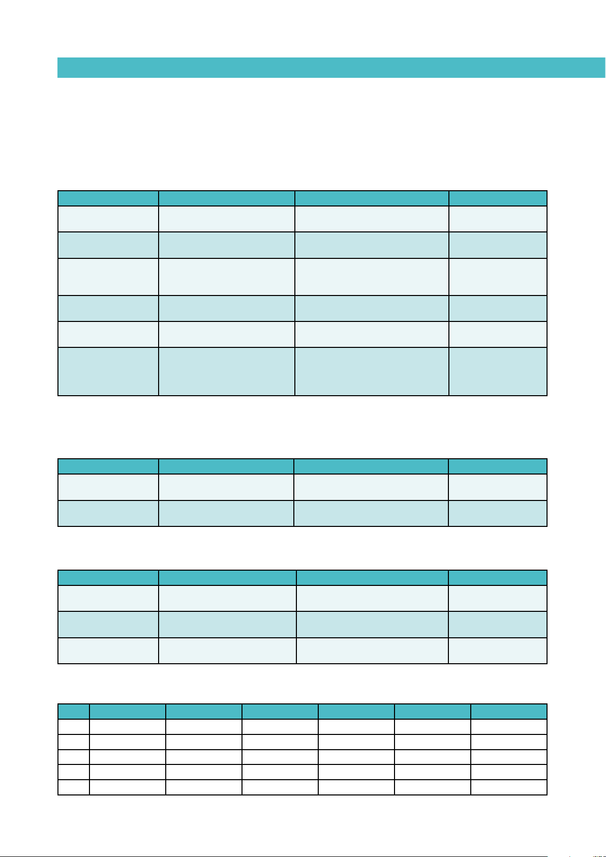
MA-5078-E MICRON ADHESIVE MELTER MANUALTROUBLESHOOTING
Gun
Gun does not heat
Causes Checking Comments Actions
Gun damaged.
Hose damaged.
Pins and wiring
damaged.
Ribbon cable wrong
placed.
Power board fuse
damaged.
Power board
damaged.
Replace the gun by another one
that works.
Replace the hose by another
one that works.
Check voltage between board
and gun-output connector (with
the hose plugged).
Observe ribbon cable
connection.
Verify fuse continuity.
( 2 )
Check voltage at the board
output (with the hose plugged).
Change gun channel. Change gun.
Change hose channel. Change hose.
CN* connector (black wire-neutral
and red wire-gun P*).
( 1 )
Ribbon cable correct if red LED
light on (DL15).
Check continuity with the unit
turned off.
Change connectors.
Put ribbon cable
correctly.
Change fuse.
CN* board connector (black wireneutral and red wire-gun P*). Fuse
shows continuity. DL* LED light
remains on.
( 3 )
Change power board.
Gun does not stop heating
Causes Checking Comments Actions
Power board
damaged.
Control board
damaged.
Check power board.
--
DL* LED green indicator is
continuously off.
DL* LED green indicator is
continuously on.
( 4 )
( 4 )
Change power board.
Change control board.
Temperature fluctuations in gun
Causes Checking Comments Actions
Gun temperature
sensor malfunction.
Sensor wiring.
Sensor board
malfunction.
Replace the gun by another one
that works.
Check sensor board and gun
connector.
Last failure option.
Change gun channel. Change gun.
CN* sensor board connector (black
and blue wire).
( 5 )
Check first sensors, connections
and wirings.
Change connector.
Change the sensor
board.
Note Gun 1 Gun 2 Gun 3 Gun 4 Gun 5 Gun 6
(1) CN9 / P1 CN9 / P2 CN10 / P3 CN10 / P4 CN11 / P5 CN11 / P6
(2) F04 F05 F06 F07 F08 F09
(3) CN9 / P1 / DL4 CN9 / P2 / DL6 CN10 / P3 / DL8 CN10/ P4 /DL10 CN11/ P5 /DL12 CN11/ P6 /DL14
(4) DL4 DL6 DL7 DL10 DL12 DL14
(5) CN2 CN3 CN4 CN5 CN6 CN7
6-9
Page 62

TROUBLESHOOTINGFOCKE MELER GLUING SOLUTIONS
This page is intentionally left blank.
6-10
Page 63

MA-5094-E MICRON MOD ADHESIVE MELTER MANUALTECHNICAL CHARACTERISTICS
7. TECHNICAL CHARACTERISTICS
Generals
Tank capacity
Melting rate
Number of outputs
Temperature range
Temperature control
Max. working pressure (at 6 bar)
Max. installation power (at 230V)
External requirements
Electrical requirements
Workplace temperature
1,21 liters
29,3 kg/h 7cc/stroke pump (*)
15.5 kg/h (*)
2, 4 or 6 (thread 9/16)
40 to 200°C (100 to 392°F)
RTD ±0.5°C (±1°F)
Pt-100 or Ni-120
80 bar (1160 psi)
4.920W (2 outputs)
7.320W (4 outputs)
9.720W (6 outputs)
Temperature ok output
Outputs disabled external control
LN ~ 230V 50Hz + PE
3N ~ 400/230V 50Hz + PE
Dimensions (L x A x H)
Weight
Options
(*) Depending on the type of adhesive
0 to 40°C
587 x 377 x 577 mm
47 kg (without automatic feeder system)
Low level warning light
Pressure regulator VP-200
7-1
Page 64
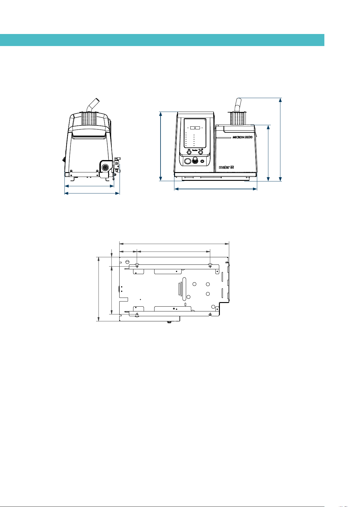
Dimensions
TECHNICAL CHARACTERISTICSFOCKE MELER GLUING SOLUTIONS
341
377
481
587
577
391
Mounting the equipment
571
92
49
334
249
381
7-2
Optional equipment
Warning light option
The adhesive level is controlled using a capacitive sensor which triggers an
alarm signal via a warning light.
VP option
The pressure regulator VP-200 allows the automatic control of working air
pressure of the equipments with piston pump. Thus, when the main machine
changes its speed, it is possible to guarantee the same application pattern,
adjusting the adhesive flow.
Page 65

8. ELECTRICAL DRAWINGS
MA-5094-E MICRON MOD ADHESIVE MELTER MANUALELECTRICAL DRAWINGS
8-1
Page 66

0 76
1
2
4
5
Poligono industrial Los Agustinos C/G Nave D-43
8 93
MELER PORTADA
31160
Phone.
Orcoyen (Navarra)
+34 948 35 11 10
Company / customer
Project description MICRON MOD PT 100
Job number
E00300072
Commission
Manufacturer (company)
Path
MELER
Pages and devices, sequential numbering
Project name E00300072
Make
Type
Place of installation
Responsible for project
Part feature
Created on
Edit date
10/02/2016
11/05/2016
by (short name)
japerez
Number of pages
11
Ed.
Updated
Appr
JOSE A PEREZ
JAPEREZ
R.F
Date
10/02/2016
28/01/2016
Denomination
TITLE PAGE
Equipment
MICRON MOD PT 100
Revision
E00300072
2
=Name
+
Page
Page
1
11
Page 67
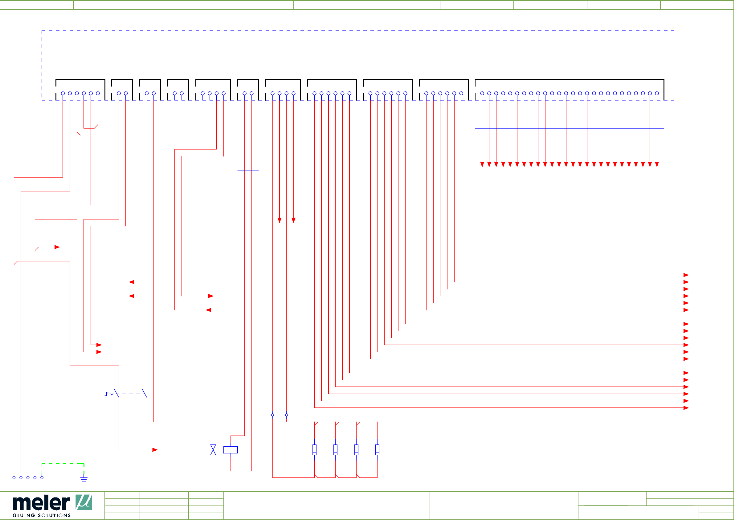
0 76
1
2
4
5
2A0
POWER BOARD
8 93
2,5
L1
BK
2.5
L2
MAIN POWER SUPPLY
CN4
BK
L3
BK
2.5
1
2 3 4 5 6
N
TQ
2.5
/
5.0
N
220 VAC ON/OFF LOW LEVEL
CN8
1
2
CN7
1
2.1
2
BK
1
2W1
4.3
2.2
BK
1
CN5
CN11
CHANNEL 5 & 6
1
2 3 4 5 6
1
2 3 4 5 6 7 8 9 10 11 12 13 14 15 16 17 18 19 20 21 22 23 24 25 26
CN3
CHANNEL 1 & 2 CHANNEL 3 & 4
CN9
1
2 3 4 5 6
CN10
1
2 3 4 5 6
2
TANK HEADER
1
2 3 4
CN6
Tª OK
CN2
PISTON
1
HOT-MELT LEVEL
1
2
CN1
1
2 3 4
2W6
4.5
4.5
4.5
4.5
4.5
4.5
4.5
4.5
4.6
4.6
4.6
4.6
4.6
4.6
4.6
4.6
4.6
4.6
4.6
4.7
4.7
4.7
4.7
4.7
4.7
4.7
4.7
BK
D1
2W3
2x0,5
1
G1
D2
BK
2,5
BK
1
G2
BK
2,5
CN3-1
CN3-2
CN3-3
CN3-4
CN3-5
CN3-6
CN3-7
CN3-8
CN3-9
CN3-10
CN3-11
CN3-12
CN3-13
CN3-14
CN3-15
CN3-16
CN3-17
CN3-18
CN3-19
CN3-20
CN3-21
CN3-22
CN3-23
CN3-24
CN3-25
CN3-26
G2
8.7G18.7
PE
8.7
8.7
220 VAC-1
220 VAC-2
2S1
/
/
2.1
2.3
1A
1B
L1.1
1
BK
P6
BK
1
T-OK
BU
0,5
+24V
BU
0,5
BK
2.3
1
/
4.0
/
4.0
T-OK
+24V
/
5.7
/
6.7
P4
1
BK
C6
BK
1
1
M6
BK
P5
BK
1
C5
BK
1
1
M5
BK
C4
BK
1
1
M4
BK
P3
BK
1
C3
BK
1
1
M3
BK
P2
BK
1
2A
2B
1 2
2X3
L1.1
/ 5.0
2Y3
2E4
1
2E4.1
2
x2
x1
300 W
300 W
1
2E4.2
160 W
2
1
2E5
160 W
2
1
2
C2
BK
1
1
M2
BK
P1
BK
1
C1
BK
1
1
M1
BK
P6
C6
M6
P5
C5
M5
P4
C4
M4
P3
C3
M3
P2
C2
M2
P1
C1
M1
/
3.0
/
3.0
/
3.0
/
3.0
/
3.0
/
3.0
/
3.0
/
3.0
/
3.0
/
3.0
/
3.0
/
3.0
/
3.0
/
3.0
/
3.0
/
3.0
/
3.0
/
3.0
XA
1
1 2 3 4 5
U1
1
MANIFOLDPUMP
3
Ed.
Updated
Appr
JOSE A PEREZ
japerez
R.F
Date
10/02/2016
11/05/2016
Denomination
POWER CIRCUIT WIRING
Equipment
MICRON MOD PT 100
Revision
E00300072
=Name
+
Page
Page
2
11
Page 68
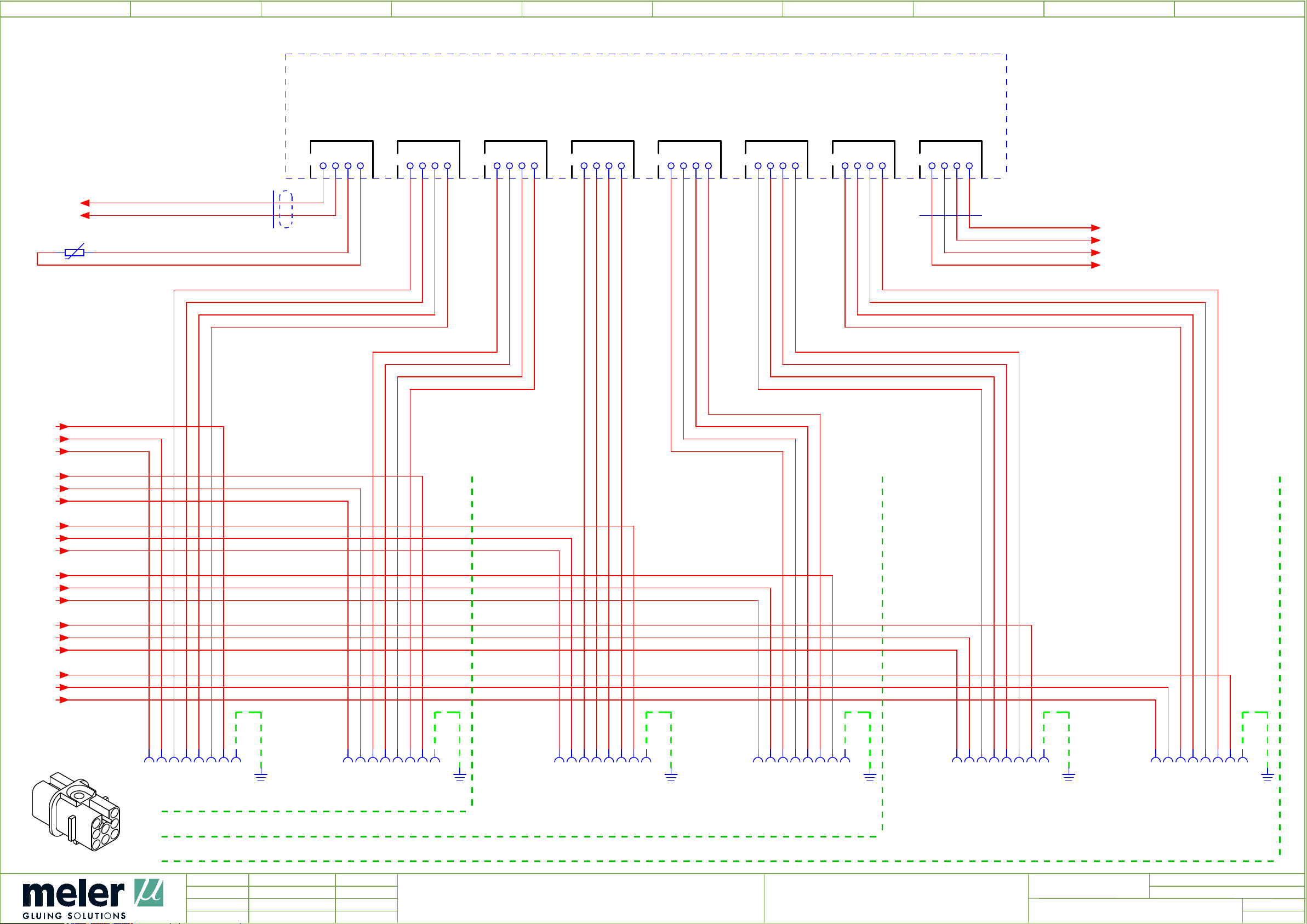
0 76
1
2
4
5
3A2
SENSORS BOARD
TANK CHANNEL 1 CHANNEL 2 CHANNEL 3 CHANNEL 4 CHANNEL 5 CHANNEL 6 CONTROL
8 93
2.9
2.9
2.9
/
/
/
M1
8.7
8.7
P1
C1
/
S1
/
S2
3B0.1
x1 x2
MANIFOLD
3W2
3.2
2x0,25
CN1
GREEN
BROWN
1
2 3 4 2 3 4
CN2
1
BLUE
BROWN
GREEN
BROWN
BLUE
BROWN
CN3
1
2 3 4
CN4
1
2 3 4
GREEN
BROWN
BLUE
BROWN
CN5
1
2 3 4
BROWN
GREEN
CN6
BROWN
BLUE
1
2 3 4
CN7
1
2 3 4
BROWN
GREEN
BROWN
BLUE
3W7
4.4
CN8
1
2 3 4
BROWN
GREEN
BROWN
BLUE
SEN-4
SEN-3
SEN-2
SEN-1
/
4.0
/
4.0
/
4.0
/
4.0
2.9
2.9
2.9
2.9
2.9
2.9
2.9
2.9
2.9
2.9
2.9
2.9
2.9
2.9
2.9
/
/
/
/
/
/
/
M2
/
/
M3
/
/
M4
/
/
M5
/
/
M6
P2
C2
P3
C3
P4
C4
P5
C5
P6
C6
3X0 =
3X0
1 2 3 4 5 6 7 PE
3.0
PE PE PE PE PE PE
U1
3X2
3X2 =
1
1 2 3 4 5 6 7 PE
3.2
1
U1
3X3 =
3X3
1 2 3 4 5 6 7 PE
3.3
U1
3X5
3X5 =
1
1 2 3 4 5 6 7 PE
3.5
1
U1
3X6 =
3X6
1 2 3 4 5 6 7 PE
3.6
U1
3X8
3X8 =
1
1 2 3 4 5 6 7 PE
3.8
1
U1
FOR UNITS 2 OUTPUTS
FOR UNITS 4 OUTPUTS
FOR UNITS 6 OUTPUTS
2
Ed.
Updated
Appr
JOSE A PEREZ
japerez
R.F
Date
10/02/2016
11/05/2016
Denomination
SENSORS CIRCUIT WIRING
Equipment
MICRON MOD PT 100
Revision
E00300072
=Name
+
Page
Page
4
3
11
Page 69
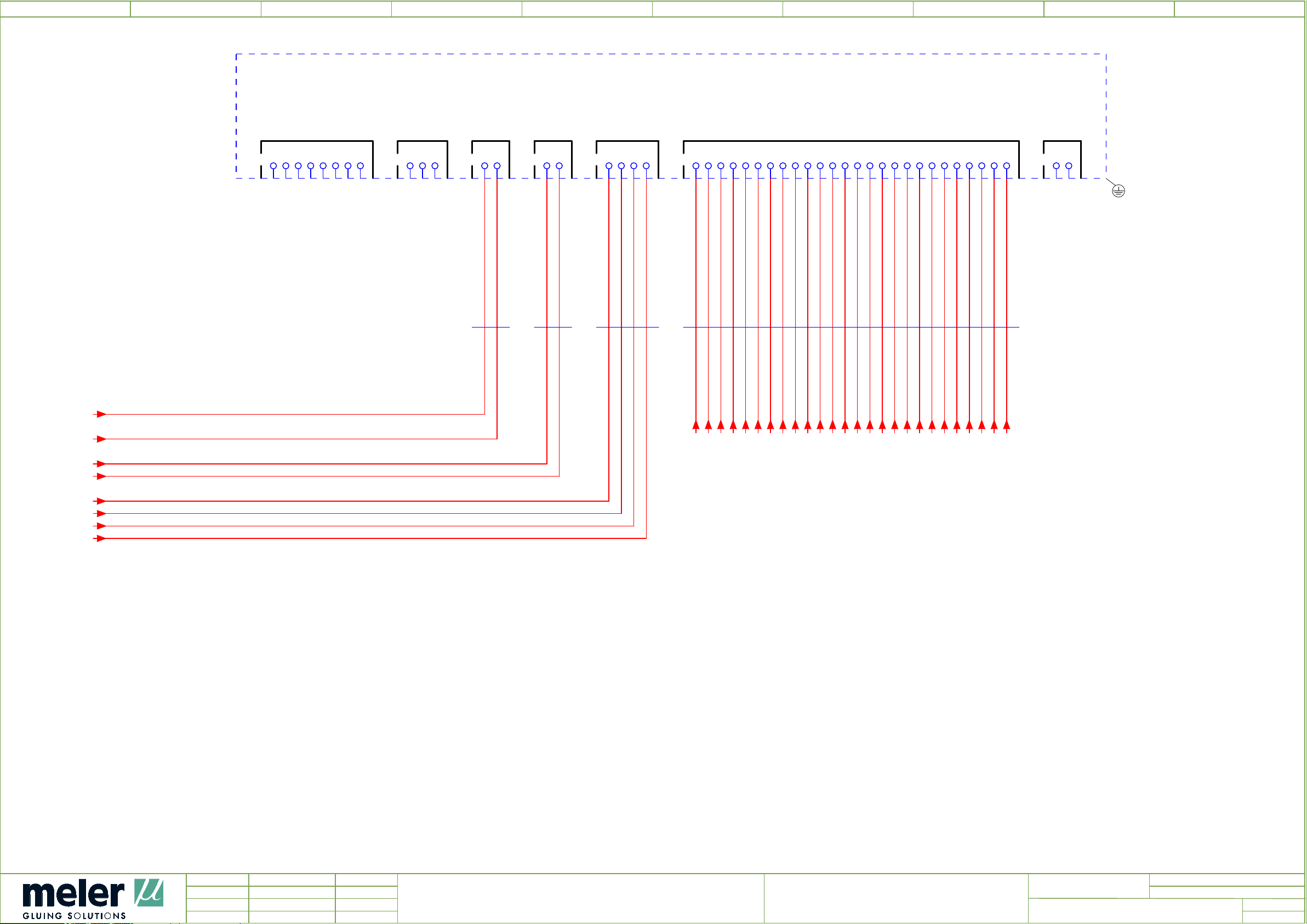
0 76
1
2
4
5
4A1
CONTROL BOARD
EXTERNAL CHANNEL ACTIVATION RS-232 220 VAC STANDBY SENSORS ON-OFF
8 93
/
2.1
220 VAC-1
/
2.1
220 VAC-2
7.9
7.9
/
Q4_1
/
Q4_2
1
2 3 4 5 6 7 8
CN5
CN10
1
2 3
CN9
1
2
CN4
1
2
CN6
1
2 3 4
1
2 3 4 5 6 7 8 9 10 11 12 13 14 15 16 17 18 19 20 21 22 23 24 25 26
CN3
CN11
1
2
7W6
2W1
2.1
7.6
2x0,25
3W7
WHBN
3.7
2W6
2.6
2.6
2.6
CN3-1
CN3-2
2.6
2.6
CN3-3
CN3-4
2.6
2.7
CN3-5
CN3-6
2.7
2.7
CN3-7
CN3-8
2.7
2.7
CN3-9
CN3-10
2.7
2.7
CN3-11
CN3-12
2.7
2.7
CN3-13
CN3-14
2.7
2.8
CN3-15
CN3-16
2.8
2.8
CN3-17
CN3-18
2.8
2.8
CN3-19
CN3-20
2.8
2.8
CN3-21
CN3-22
2.8
2.8
CN3-23
CN3-24
2.8
2.8
CN3-25
CN3-26
3.8
3.8
3.8
3.8
/
SEN-1
/
SEN-2
/
SEN-3
/
SEN-4
3
Ed.
Updated
Appr
JOSE A PEREZ
japerez
R.F
Date
10/02/2016
11/05/2016
Denomination
CONTROL CIRCUIT WIRING
Equipment
MICRON MOD PT 100
Revision
E00300072
=Name
+
Page
Page
5
4
11
Page 70
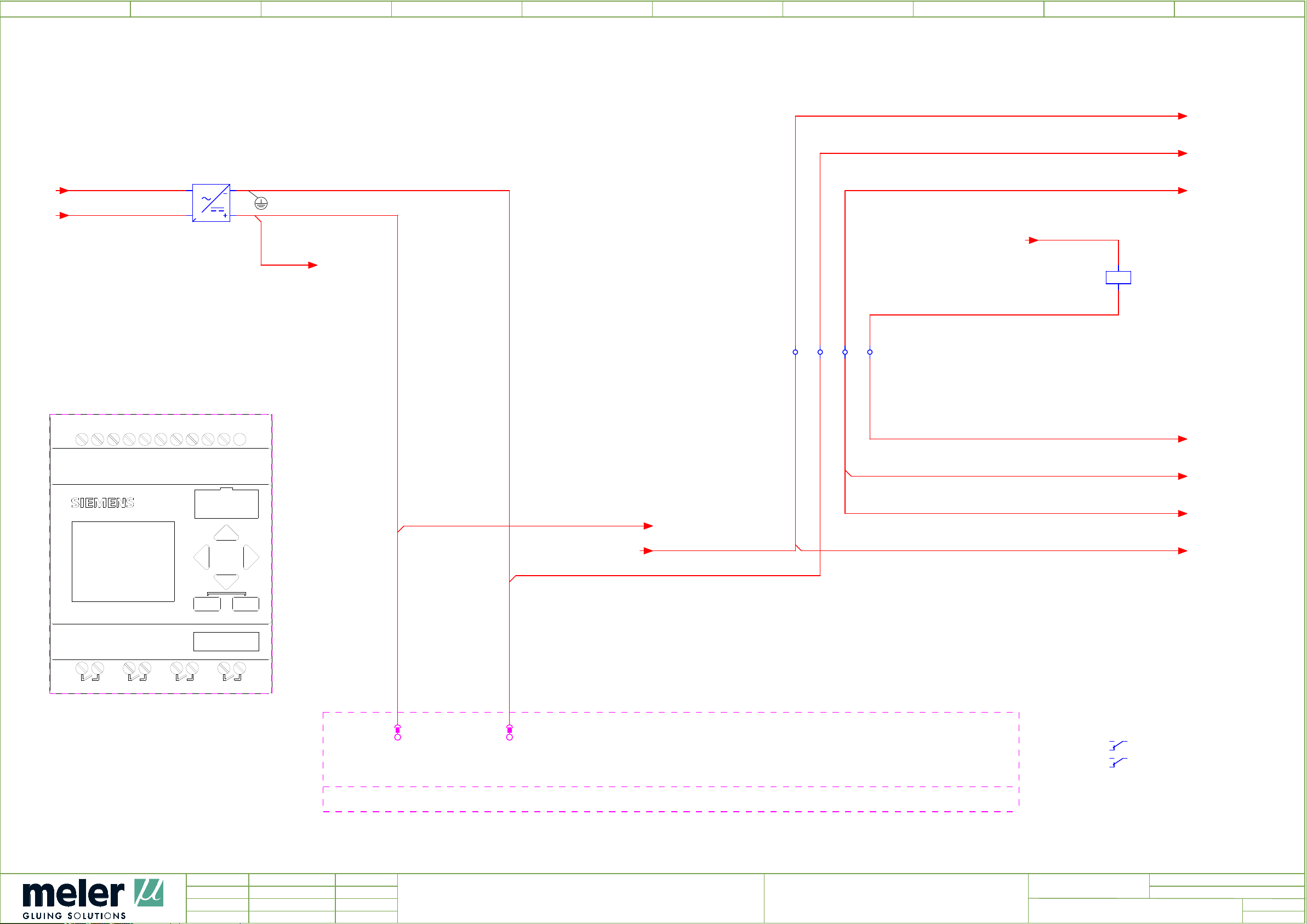
0 76
1
2
4
5
8 93
2.2
/
2.0
L1.1
/
N
5A2
5.2
L+
X10
DC 21/24V
INPUT 8xDC
BU
BN
+24V
/
0V
6.0
/
6.0
5V1
L1.1
1
N
1
BK
TQ
L 0V
AC
N +24V
-
AC
24 V
1,1 A
+24V
BU
0,5
+24V
+24V
BU
0,5
/
2.2
T-OK
/
6.6
T-OK
0,5
BU
A1
+24V
/
8.7
5K8
24VDC
A2
0V
BU
0,5
1.1 1.2 2.1 2.2
XC
BU
+24V
0,5
M
I2
I1
I3
I5 I6 I7
I4
I1, I2 = AI3, AI4 (0...10V)
I7, I8 = AI1, AI2 (0...10V)
I8
0V
BU
0,5
TEMPERATURE OK
0V
BU
0,5
+24V
BU
0,5
/
0V
+24V
7.0
/
7.1
2
12/24RC
1
LOGO!
OUTPUT 4xRELAY/10A
X11
1
Q1
X50
+24V
BU
0,5
/
6.7
+24V
ESC
6ED1052-1MD00-0BA6
2
Q2
2
1
Q3
OK
2
1
Q4
5A2
5.0
6.1
7.1
-X10
X10/1/L+
L+
1
-X10
X10/2/M
M
2
+24V
/
6.5
+24V
BU
0,5
Rack X
Slot Y
+24V
BU
0,5
RD
/
+24V
+24V
1114 6.6
12
2124 7.8
22
7.2
/
7.1
SIEMENS6ED1052-1MD00-0BA6 12/24RC, 8DI(4AI)/4DO 200 BLOCKS X10
4
Ed.
Updated
Appr
JOSE A PEREZ
japerez
R.F
Date
10/02/2016
11/05/2016
Denomination
PLC
Equipment
MICRON MOD PT 100
Revision
E00300072
=Name
+
Page
Page
6
5
11
Page 71
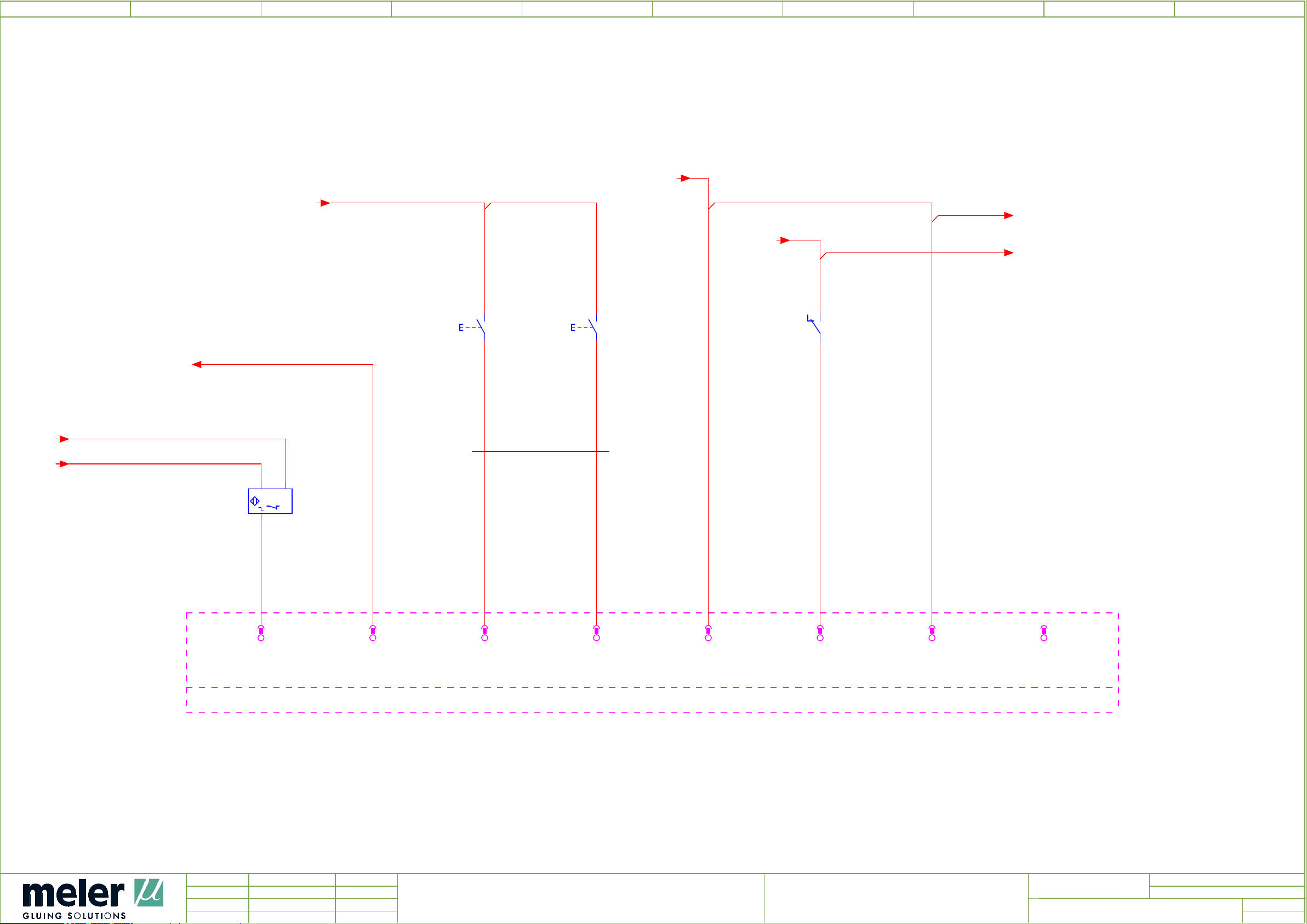
0 76
1
/
7.5
+24V
2
+24V
BU
0,5
4
/
5.4
+24V
5
+24V
BU
0,5
/
5.2
+24V
+24V
+24V
8 93
/
5.4
/
2.2
5.9
5.9
/
+24V
8.7
13
6S3
14
/
I2
6S4
13
121114
5K8
14
5.8
6W3
/
0V
BU
7.3
7.4
8x0,25
BN WH
BN
132
+ -
6B2
5A2
5.2
-X10
I1
I1
X10/3/I1
6B2:3
-X10
I2
I2
X10/4/I2
8X5:PE
BU
0,5
4
BK
3
-X10
I3
I3
X10/5/I3
6S3:14
DI
5
BN
0,25
-X10
I4
I4
X10/6/I4
6S4:14
DI
6
WH
0,25
+24V
-X10
I5
X10/7/I5
5A2:-X10:1
BU
0,5
DI
7
-X10
I6
I6
X10/8/I6
5K8:11
BU
0,5
DI
8
+24V
-X10
I7
X10/9/I7
5A2:-X10:7
BU
0,5
9
-X10
I8
X10/10/I8
10
SIEMENS6ED1052-1MD00-0BA6 12/24RC, 8DI(4AI)/4DO 200 BLOCKS X10
LID SENSOR
LEVEL SENSOR
RESET TEMPERATURE OK
5
Ed.
Updated
Appr
JOSE A PEREZ
japerez
R.F
Date
10/02/2016
11/05/2016
Denomination
PLC DI
Equipment
MICRON MOD PT 100
FEEDER MODESTOP BUZZER
7
Revision
E00300072
=Name
+
Page
Page
6
11
Page 72
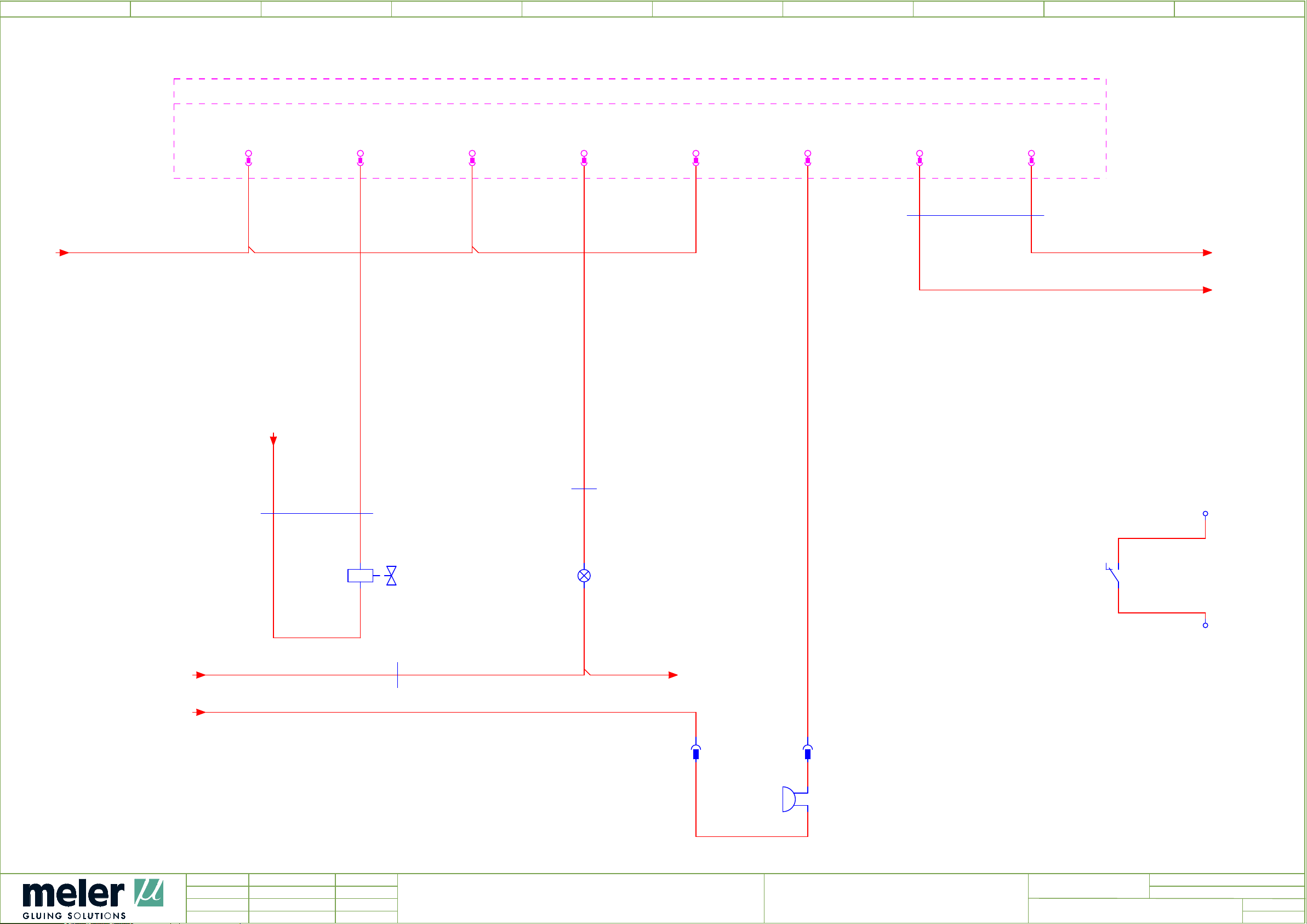
0 76
1
TEMPERATURE OK
2
4
5
8 93
5.9
5A2
5.2
X11
X11/1/Q1_1
Q1
1
-X11 2
DQ1_1
X11/2/Q1_2
-X11 3
DQ1_2
X11/3/Q2_1
Q2
-X11 4
DQ2_1
X11/4/Q2_2
-X11 5
DQ2_2
X11/5/Q3_1
Q3
-X11 6
DQ3_1
X11/6/Q3_2
-X11 7
DQ3_2
X11/7/Q4_1
Q4
-X11 8
DQ4_1
X11/8/Q4_2
-X11
SIEMENS6ED1052-1MD00-0BA6 12/24RC, 8DI(4AI)/4DO 200 BLOCKS
DQ4_2
7W6
4.4
2x0,25
/
0V
WHBN
Q4_2
0,25
Q4_1
0,25
WH
BN
Q4_2
Q4_1
/ 4.0
/ 4.0
5.9
5.9
/
+24V
/
+24V
7W2
2x0,5
5.9
+24V
BN BU
7Y2
BU
Q1_2
0,5
x1
x2
8x0,25
6W3
6.3
RD
6W3
6.3
8x0,25
7H4
YE
Q2_2
0,25
YE
x1
x2
+24V
BU
Q3_2
0,5
XTOK
1
TOK1
BU
0,5
222124
5K8
5.8
TOK2
BU
0,5
/
6.2
2
7X5
LOAD E.V. RESET
7X5 =
7X5.1 =
7X5.1
1 2
7.4
1 2
7.4
x1
7H6
x2
6
Ed.
Updated
Appr
JOSE A PEREZ
japerez
R.F
Date
10/02/2016
11/05/2016
Denomination
PLC DO
BUZZER
Equipment
MICRON MOD PT 100
Revision
E00300072
8
=Name
+
Page
Page
7
11
Page 73
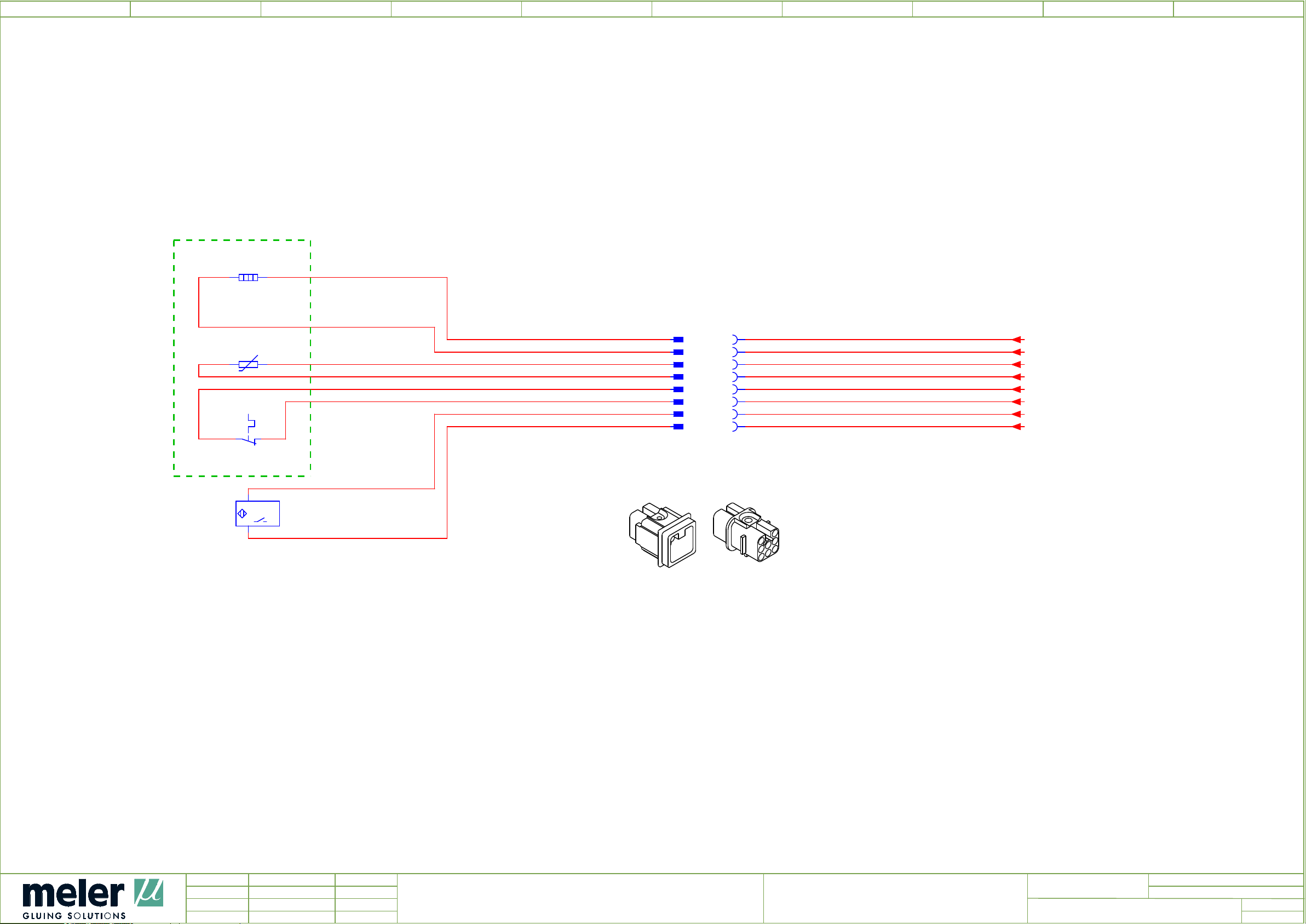
0 76
1
2
4
5
8E1
1 2
1600 W
2,5
G1
BK
8 93
8B1
x1 x2
8S1
1112
GRID
13
8B1.1
14
MAGNETIC SENSOR
1
0,5
0,5
2.1
24V
I2
2,5
BK
BU
BU
G2
BK
2.3
1
BK
8X4 =
8X4
1
PE
8X5 =
8.4
2
3
4
5
6
7
8X5
1
2
3
4
5
6
7
PE
8.5
/
G1
/
G2
/
S1
/
S2
/
2.1
/
2.3
+24V
/
6.1
I2
2.4
2.3
3.0
3.0
2.1
2.1
/
5.9
7
Ed.
Updated
Appr
JOSE A PEREZ
japerez
R.F
Date
10/02/2016
11/05/2016
Denomination
GRID
Equipment
MICRON MOD PT 100
Revision
E00300072
=Name
+
Page
Page
9
8
11
Page 74

0 76
1
2
4
5
8 93
Parts list
Placement QU
2.0
3.2
4.1
5.2
3.0
6.2
8.1
QuantityDevice tag
12A0
POWER BOARD
SIX OUTPUTS
13A2 SENSORS BOARD
14A1 CONTROL BOARD
15A2
LOGO 0BA8
6ED1052-1MD00-0BA8
13B0.1 TEMPERATURE SENSOR TYPE PT 100
16B2
CAPACITIVE SENSOR
RECHNER 85MM Ø10 CABLE 1M+BRIDA
18B1 TEMPERATURE SENSOR TYPE PT 100
MELER_ARTICULOS_PRODUCTO_V2
Designation
8.1
2.4
2.4
2.4
2.5
8.1
7.4
7.6
5.8
18B1.1
MAGNETICALLY OPERATED SWITCH
.
12E4
CARTRIDGE HEATER 300W 230V
9.46 (3/8") X 177
12E4.1
CARTRIDGE HEATER 300W 230V
Ø10x180
12E4.2
CARTRIDGE HEATER 160W 230V
Ø10X160
12E5
CARTRIDGE HEATER 160W 230V
Ø10X160
18E1
HEATER 1600W 230V
MICRON MOD GRID
17H4 YELLOW LED
17H6 BUZZER
15K8 24VDC RELAY WITH TWO CO CONTACTS
12S1 ON - OFF SWITCH
2.1
.
16S3 NO CONTACT
6.3
8
Ed.
Updated
Appr
JOSE A PEREZ
japerez
R.F
Date
10/02/2016
11/05/2016
Denomination
PARTS LIST
Equipment
MICRON MOD PT 100
Revision
E00300072
=Name
+
Page
Page
9.a
9
11
Page 75

0 76
1
2
4
5
8 93
Parts list
Placement QU
6.4
8.1
5.1
2.3
6.3
7.2
7.6
QuantityDevice tag
16S4
18S1
NO CONTACT
SAFETY THERMOSTAT
15V1 POWER SUPPLY 24VDC 1,1A
12W3 FLEXIBLE CABLE 0,6/1KV (2 X 0,5)
16W3 CABLE HOSE DATAFLEX YCY 500V 8x0,22
17W2 FLEXIBLE CABLE 0,6/1KV (2 X 0,5)
17W6 SHIELDED CABLE DATAFLEX YCY 2 X 0.25
MELER_ARTICULOS_PRODUCTO_V2
Designation
2.3
3.0
3.2
3.3
3.5
3.6
3.8
7.4
7.4
12X3 CERAMIC TERMINAL BLOCK
13X0 FEMALE INSERT 8P
13X2 FEMALE INSERT 8P
13X3 FEMALE INSERT 8P
13X5 FEMALE INSERT 8P
13X6 FEMALE INSERT 8P
13X8 FEMALE INSERT 8P
17X5 FEMALE INSERT 2 P
17X5.1 MALE INSERT 2P
18X4 MALE INSERT 8P
8.4
18X5 FEMALE INSERT 8P
8.5
9
Ed.
Updated
Appr
JOSE A PEREZ
japerez
R.F
Date
10/02/2016
11/05/2016
Denomination
PARTS LIST
Equipment
MICRON MOD PT 100
Revision
E00300072
=Name
+
Page
Page
9.b
9.a
11
Page 76

0 76
1
2
4
5
8 93
Parts list
Placement QU
2.0
2.0
2.0
5.6
7.9
7.2
QuantityDevice tag
3XA FEED-THROUGH TERMINAL, 6MM², SCREW CONNECTION, BEIGE TS 35
1XA FEED-THROUGH TERMINAL, 6MM², SCREW CONNECTION, BLUE TS 35
1XA EARTH TERMINAL, 6MM², SCREW CONNECTION, GREEN/YELLOW TS 35
2XC FEED-THROUGH TERMINAL, DOUBLE-TIER, 2,5 MM², TENSION CLAMP CONNECTION,BEIGE TS 35
1XTOK FEED-THROUGH TERMINAL, DOUBLE-TIER, 2,5 MM², TENSION CLAMP CONNECTION,BEIGE TS 35
17Y2
SOLENOID VALVE
2/2 24V CC 10W
MELER_ARTICULOS_PRODUCTO_V2
Designation
9.a
Ed.
Updated
Appr
JOSE A PEREZ
japerez
R.F
Date
10/02/2016
11/05/2016
Denomination
PARTS LIST
Equipment
MICRON MOD PT 100
Revision
E00300072
=Name
+
Page
Page
9.b
11
Page 77

0 76
1
2
4
5
Poligono industrial Los Agustinos C/G Nave D-43
8 93
MELER PORTADA
31160
Phone.
Orcoyen (Navarra)
+34 948 35 11 10
Company / customer
Project description MICRON MOD NI 120
Job number
E00300082
Commission
Manufacturer (company)
Path
MELER
Pages and devices, sequential numbering
Project name E00300082
Make
Type
Place of installation
Responsible for project
Part feature
Created on
Edit date
10/02/2016
11/05/2016
by (short name)
japerez
Number of pages
11
Ed.
Updated
Appr
JOSE A PEREZ
JAPEREZ
R.F
Date
10/02/2016
28/01/2016
Denomination
TITLE PAGE
Equipment
MICRON MOD NI 120
Revision
E00300082
2
=Name
+
Page
Page
1
11
Page 78
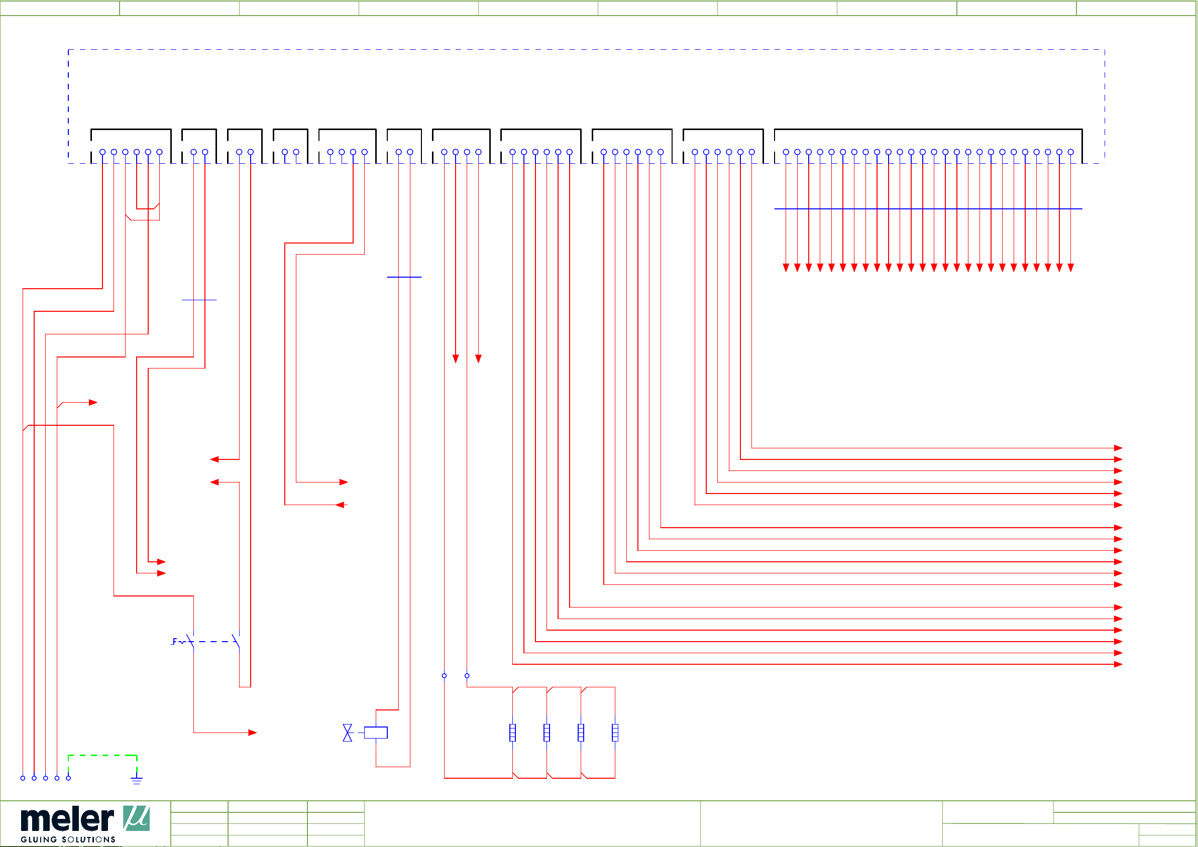
0 76
1
2
4
5
2A0
POWER BOARD
8 93
2,5
L1
BK
2.5
L2
MAIN POWER SUPPLY
CN4
BK
L3
BK
2.5
1
2 3 4 5 6
N
TQ
2.5
/
5.0
N
220 VAC ON/OFF LOW LEVEL
CN8
1
2
CN7
1
2.1
2
BK
1
2W1
4.3
2.2
BK
CN5
CHANNEL 1 & 2 CHANNEL 3 & 4
CN9
1
2 3 4 5 6
CN10
1
2 3 4 5 6
2
TANK HEADER
1
2 3 4
CN6
Tª OK
CN2
PISTON
1
HOT-MELT LEVEL
1
2
CN1
1
2 3 4
CN11
CHANNEL 5 & 6
1
2 3 4 5 6
1
2 3 4 5 6 7 8 9 10 11 12 13 14 15 16 17 18 19 20 21 22 23 24 25 26
CN3
2W6
4.5
4.5
4.5
4.5
4.5
4.5
4.5
4.5
4.6
4.6
4.6
4.6
4.6
4.6
4.6
4.6
4.6
4.6
4.6
4.7
4.7
4.7
4.7
4.7
4.7
4.7
4.7
BK
D1
1
G1
D2
BK
2,5
BK
1
G2
BK
2,5
2W3
2x0,5
1
CN3-1
CN3-2
CN3-3
CN3-4
CN3-5
CN3-6
CN3-7
CN3-8
CN3-9
CN3-10
CN3-11
CN3-12
CN3-13
CN3-14
CN3-15
CN3-16
CN3-17
CN3-18
CN3-19
CN3-20
CN3-21
CN3-22
CN3-23
CN3-24
CN3-25
CN3-26
G2
8.7G18.7
PE
8.7
8.7
220 VAC-1
220 VAC-2
2S1
/
/
2.1
2.3
1A
1B
L1.1
1
BK
P6
BK
1
T-OK
BU
0,5
+24V
BU
0,5
BK
2.3
1
/
4.0
/
4.0
T-OK
+24V
/
5.7
/
6.7
P4
1
BK
C6
BK
1
1
M6
BK
P5
BK
1
C5
BK
1
1
M5
BK
C4
BK
1
1
M4
BK
P3
BK
1
C3
BK
1
1
M3
BK
P2
BK
1
2A
2B
1 2
2X3
L1.1
/ 5.0
2Y3
2E4
1
2E4.1
2
x2
x1
300 W
300 W
1
2E4.2
160 W
2
1
2E5
160 W
2
1
2
C2
BK
1
1
M2
BK
P1
BK
1
C1
BK
1
1
M1
BK
P6
C6
M6
P5
C5
M5
P4
C4
M4
P3
C3
M3
P2
C2
M2
P1
C1
M1
/
3.0
/
3.0
/
3.0
/
3.0
/
3.0
/
3.0
/
3.0
/
3.0
/
3.0
/
3.0
/
3.0
/
3.0
/
3.0
/
3.0
/
3.0
/
3.0
/
3.0
/
3.0
XA
1
1 2 3 4 5
U1
1
MANIFOLDPUMP
3
Ed.
Updated
Appr
JOSE A PEREZ
japerez
R.F
Date
10/02/2016
11/05/2016
Denomination
POWER CIRCUIT WIRING
Equipment
MICRON MOD NI 120
Revision
E00300082
=Name
+
Page
Page
2
11
Page 79
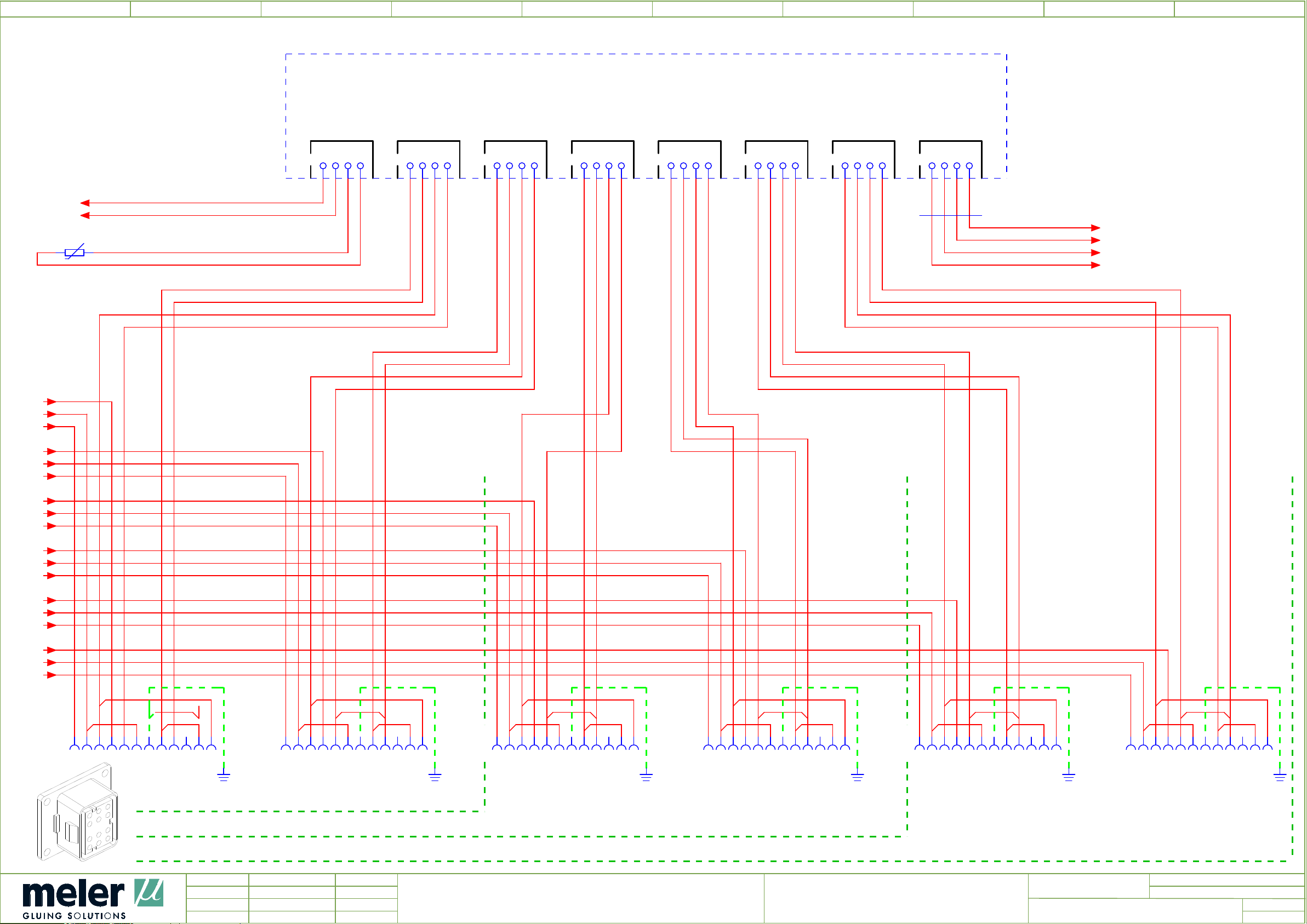
0 76
1
2
4
5
3A2
SENSORS BOARD
TANK CHANNEL 1 CHANNEL 2 CHANNEL 3 CHANNEL 4 CHANNEL 5 CHANNEL 6 CONTROL
8 93
2.9
2.9
2.9
2.9
2.9
2.9
/
/
/
/
/
/
M1
C1
P1
M2
C2
P2
/
8.7
S1
/
8.7
S2
3B0.1
x1 x2
MANIFOLD
CN1
GREEN
BROWN
1
2 3 4 2 3 4
CN2
1
BLUE
BROWN
GREEN
BROWN
BLUE
BROWN
CN3
1
2 3 4
CN4
1
2 3 4
GREEN
BROWN
BLUE
BROWN
CN5
1
2 3 4
GREEN
BROWN
BLUE
BROWN
CN6
1
2 3 4
CN7
BROWN
GREEN
1
BROWN
BLUE
2 3 4
3W7
4.4
CN8
1
2 3 4
BROWN
GREEN
BROWN
BLUE
SEN-4
SEN-3
SEN-2
SEN-1
/
4.0
/
4.0
/
4.0
/
4.0
2.9
2.9
2.9
2.9
2.9
2.9
2.9
2.9
2.9
2.9
2.9
2.9
/
M3
/
C3
/
P3
/
M4
/
C4
/
P4
/
M5
/
C5
/
P5
/
M6
/
C6
/
P6
3X0 =
3X0
3.0
PE PEPE PE PE PE
1
2 3 4 5 6 7 8 9 10 11 12
FOR UNITS 2 OUTPUTS
U1
1
3X1 =
3X1
3.1
1
2 3 4 5 6 7 8 9 10 11 12
U1
1
3X3 =
3X3
1
2 3 4 5 6 7 8 9 10 11 12
3.3
U1
1
3X5 =
3X5
3.5
1
2 3 4 5 6 7 8 9 10 11 12
U1
1
3X6 =
3X6
3.6
1
2 3 4 5 6 7 8 9 10 11 12
U1
1
3X8 =
3X8
3.8
1
2 3 4 5 6 7 8 9 10 11 12
1
U1
FOR UNITS 4 OUTPUTS
FOR UNITS 6 OUTPUTS
2
Ed.
Updated
Appr
JOSE A PEREZ
japerez
R.F
Date
10/02/2016
11/05/2016
Denomination
SENSORS CIRCUIT WIRING
Equipment
MICRON MOD NI 120
Revision
E00300082
=Name
+
Page
Page
4
3
11
Page 80
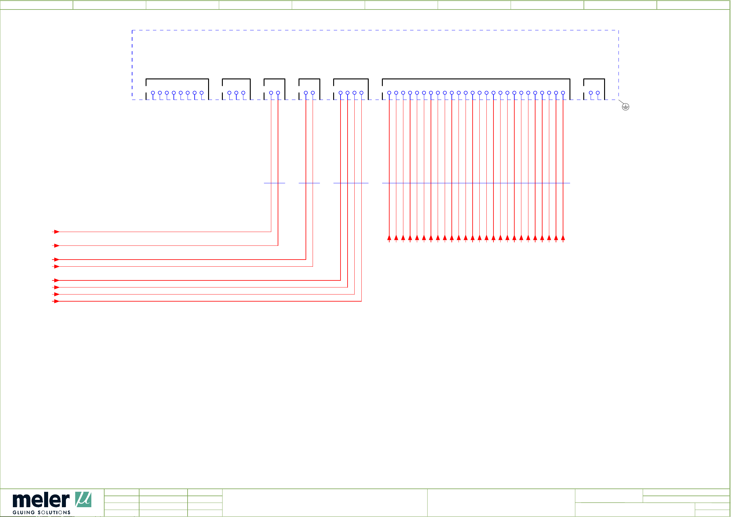
0 76
1
2
4
5
4A1
CONTROL BOARD
EXTERNAL CHANNEL ACTIVATION RS-232 220 VAC STANDBY SENSORS ON-OFF
8 93
/
2.1
220 VAC-1
/
2.1
220 VAC-2
7.9
7.9
/
Q4_1
/
Q4_2
1
2 3 4 5 6 7 8
CN5
CN10
1
2 3
CN9
1
2
CN4
1
2
CN6
1
2 3 4
1
2 3 4 5 6 7 8 9 10 11 12 13 14 15 16 17 18 19 20 21 22 23 24 25 26
CN3
CN11
1
2
7W6
2W1
2.1
7.6
2x0,25
3W7
WHBN
3.7
2W6
2.6
2.6
2.6
CN3-1
CN3-2
2.6
2.6
CN3-3
CN3-4
2.6
2.7
CN3-5
CN3-6
2.7
2.7
CN3-7
CN3-8
2.7
2.7
CN3-9
CN3-10
2.7
2.7
CN3-11
CN3-12
2.7
2.7
CN3-13
CN3-14
2.7
2.8
CN3-15
CN3-16
2.8
2.8
CN3-17
CN3-18
2.8
2.8
CN3-19
CN3-20
2.8
2.8
CN3-21
CN3-22
2.8
2.8
CN3-23
CN3-24
2.8
2.8
CN3-25
CN3-26
3.8
3.8
3.8
3.8
/
SEN-1
/
SEN-2
/
SEN-3
/
SEN-4
3
Ed.
Updated
Appr
JOSE A PEREZ
japerez
R.F
Date
10/02/2016
11/05/2016
Denomination
CONTROL CIRCUIT WIRING
Equipment
MICRON MOD NI 120
Revision
E00300082
=Name
+
Page
Page
5
4
11
Page 81
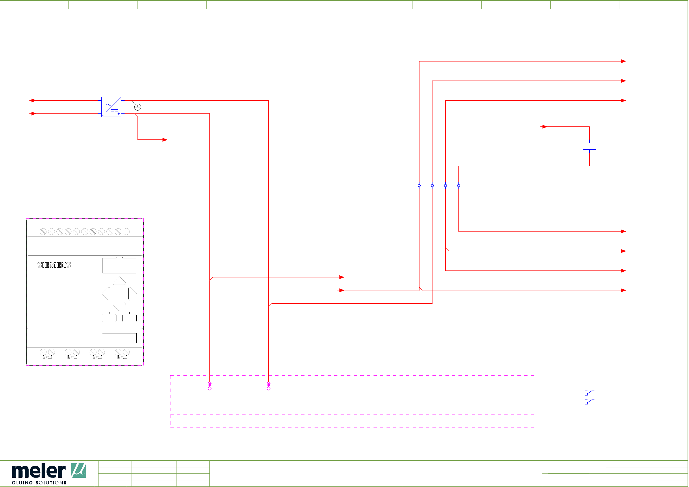
0 76
1
2
4
5
8 93
2.2
/
2.0
L1.1
/
N
5A2
5.2
L+
X10
DC 21/24V
INPUT 8xDC
BU
BN
+24V
/
0V
6.0
/
6.0
5V1
L1.1
1
N
1
BK
TQ
L 0V
AC
N +24V
-
AC
24 V
1,1 A
+24V
BU
0,5
+24V
+24V
BU
0,5
/
2.2
T-OK
/
6.6
T-OK
0,5
BU
A1
+24V
/
8.7
5K8
24VDC
A2
0V
BU
0,5
1.1 1.2 2.1 2.2
XC
BU
+24V
0,5
M
I2
I1
I3
I5 I6 I7
I4
I1, I2 = AI3, AI4 (0...10V)
I7, I8 = AI1, AI2 (0...10V)
I8
0V
BU
0,5
TEMPERATURE OK
0V
BU
0,5
+24V
BU
0,5
/
0V
+24V
7.0
/
7.1
2
12/24RC
1
LOGO!
OUTPUT 4xRELAY/10A
X11
1
Q1
X50
+24V
BU
0,5
/
6.7
+24V
ESC
6ED1052-1MD00-0BA6
2
Q2
2
1
Q3
OK
2
1
Q4
5A2
5.0
6.1
7.1
-X10
X10/1/L+
L+
1
-X10
X10/2/M
M
2
+24V
/
6.5
+24V
BU
0,5
Rack X
Slot Y
+24V
BU
0,5
RD
/
+24V
+24V
1114 6.6
12
2124 7.8
22
7.2
/
7.1
SIEMENS6ED1052-1MD00-0BA6 12/24RC, 8DI(4AI)/4DO 200 BLOCKS X10
4
Ed.
Updated
Appr
JOSE A PEREZ
japerez
R.F
Date
10/02/2016
11/05/2016
Denomination
PLC
Equipment
MICRON MOD NI 120
Revision
E00300082
=Name
+
Page
Page
6
5
11
Page 82
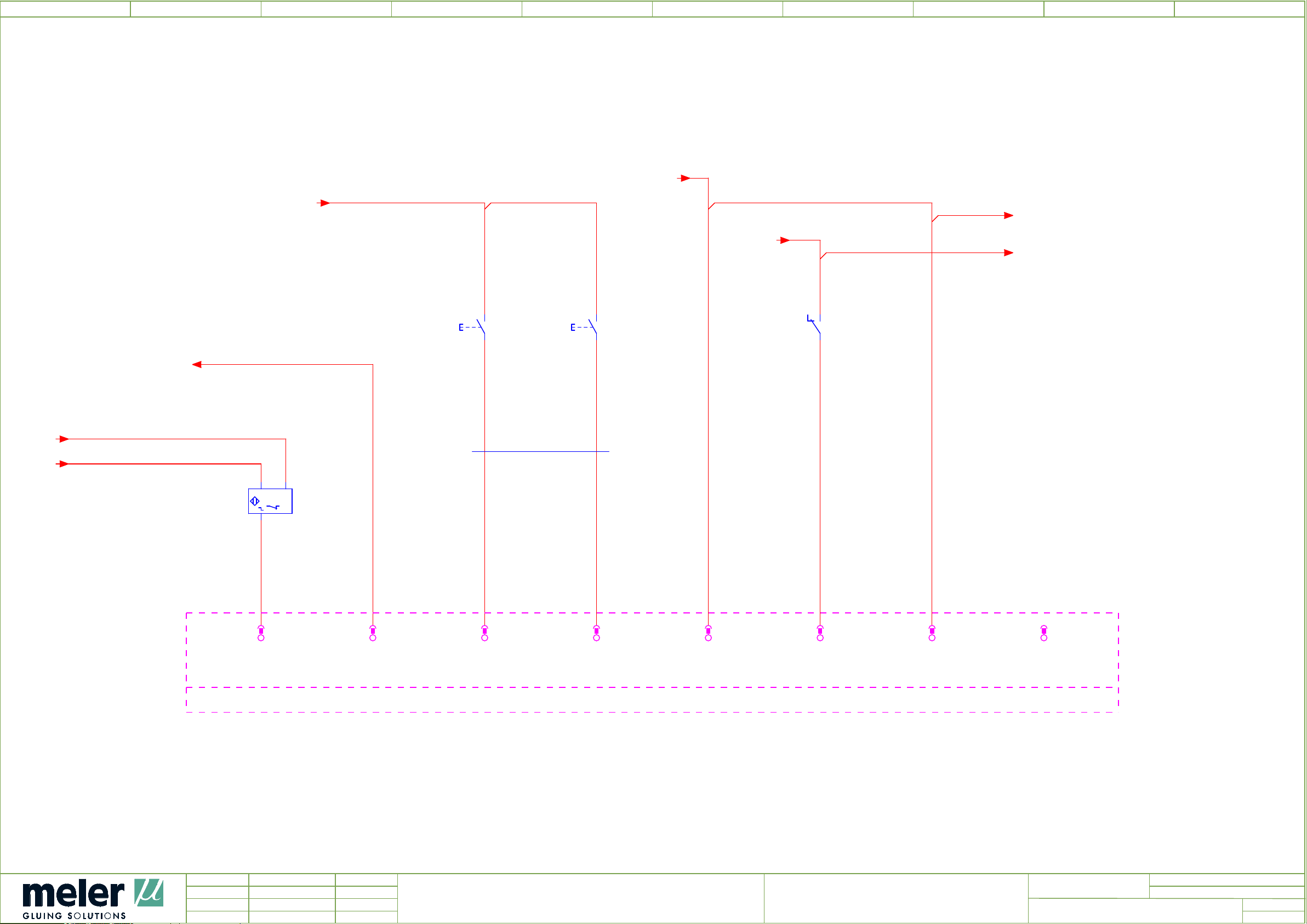
0 76
1
/
7.5
+24V
2
+24V
BU
0,5
4
/
5.4
+24V
5
+24V
BU
0,5
/
5.2
+24V
+24V
+24V
8 93
/
5.4
/
2.2
5.9
5.9
/
+24V
8.7
13
6S3
14
/
I2
6S4
13
121114
5K8
14
5.8
6W3
/
0V
BU
7.3
7.4
8x0,25
BN WH
BN
132
+ -
6B2
5A2
5.2
-X10
I1
I1
X10/3/I1
6B2:3
-X10
I2
I2
X10/4/I2
8X5:PE
BU
0,5
4
BK
3
-X10
I3
I3
X10/5/I3
6S3:14
DI
5
BN
0,25
-X10
I4
I4
X10/6/I4
6S4:14
DI
6
WH
0,25
+24V
-X10
I5
X10/7/I5
5A2:-X10:1
BU
0,5
DI
7
-X10
I6
I6
X10/8/I6
5K8:11
BU
0,5
DI
8
+24V
-X10
I7
X10/9/I7
5A2:-X10:7
BU
0,5
9
-X10
I8
X10/10/I8
10
SIEMENS6ED1052-1MD00-0BA6 12/24RC, 8DI(4AI)/4DO 200 BLOCKS X10
LID SENSOR
LEVEL SENSOR
RESET TEMPERATURE OK
5
Ed.
Updated
Appr
JOSE A PEREZ
japerez
R.F
Date
10/02/2016
11/05/2016
Denomination
PLC DI
Equipment
MICRON MOD NI 120
FEEDER MODESTOP BUZZER
7
Revision
E00300082
=Name
+
Page
Page
6
11
Page 83
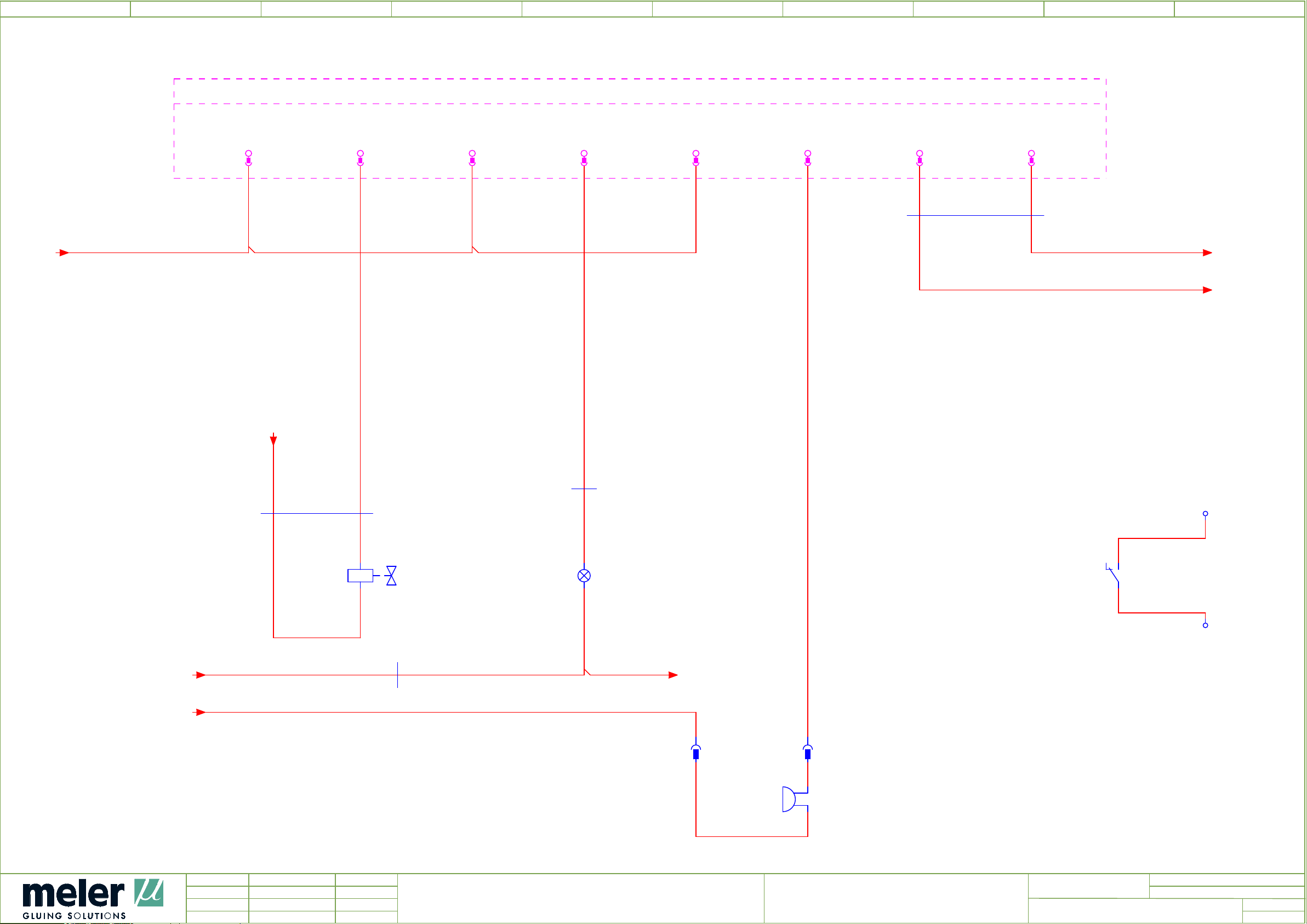
0 76
1
TEMPERATURE OK
2
4
5
8 93
5.9
5A2
5.2
X11
X11/1/Q1_1
Q1
1
-X11 2
DQ1_1
X11/2/Q1_2
-X11 3
DQ1_2
X11/3/Q2_1
Q2
-X11 4
DQ2_1
X11/4/Q2_2
-X11 5
DQ2_2
X11/5/Q3_1
Q3
-X11 6
DQ3_1
X11/6/Q3_2
-X11 7
DQ3_2
X11/7/Q4_1
Q4
-X11 8
DQ4_1
X11/8/Q4_2
-X11
SIEMENS6ED1052-1MD00-0BA6 12/24RC, 8DI(4AI)/4DO 200 BLOCKS
DQ4_2
7W6
4.4
2x0,25
/
0V
WHBN
Q4_2
0,25
Q4_1
0,25
WH
BN
Q4_2
Q4_1
/ 4.0
/ 4.0
5.9
5.9
/
+24V
/
+24V
7W2
2x0,5
5.9
+24V
BN BU
7Y2
BU
Q1_2
0,5
x1
x2
8x0,25
6W3
6.3
RD
6W3
6.3
8x0,25
7H4
YE
Q2_2
0,25
YE
x1
x2
+24V
BU
Q3_2
0,5
XTOK
1
TOK1
BU
0,5
222124
5K8
5.8
TOK2
BU
0,5
/
6.2
2
7X5
LOAD E.V. RESET
7X5 =
7X5.1 =
7X5.1
1 2
7.4
1 2
7.4
x1
7H6
x2
6
Ed.
Updated
Appr
JOSE A PEREZ
japerez
R.F
Date
10/02/2016
11/05/2016
Denomination
PLC DO
BUZZER
Equipment
MICRON MOD NI 120
Revision
E00300082
8
=Name
+
Page
Page
7
11
Page 84
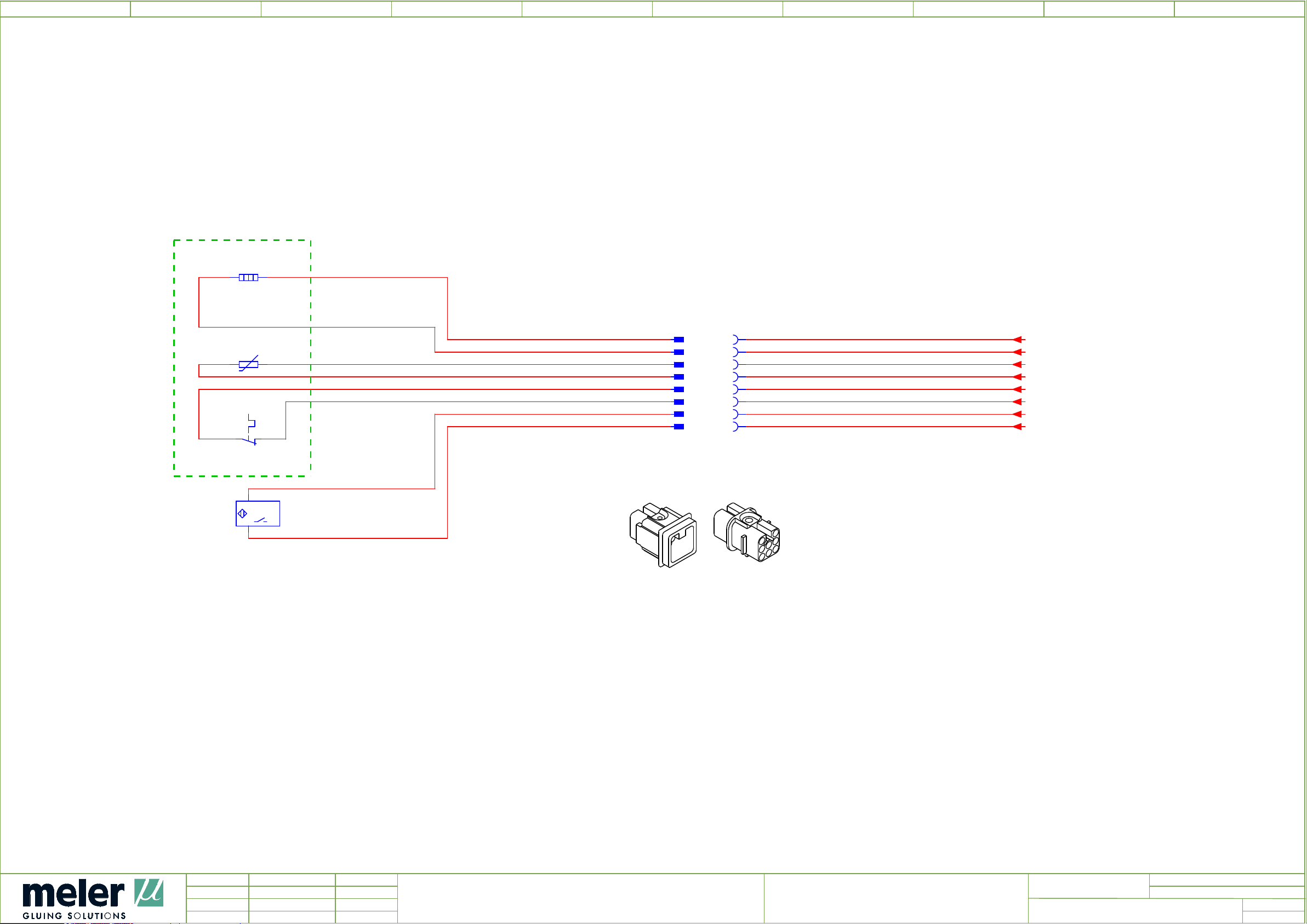
0 76
1
2
4
5
8E1
1 2
1600 W
2,5
G1
BK
8 93
8B1
x1 x2
8S1
1112
GRID
13
8B1.1
14
MAGNETIC SENSOR
1
0,5
0,5
2.1
24V
I2
2,5
BK
BU
BU
G2
BK
2.3
1
BK
8X4 =
8X4
1
PE
8X5 =
8.4
2
3
4
5
6
7
8X5
1
2
3
4
5
6
7
PE
8.5
/
G1
/
G2
/
S1
/
S2
/
2.1
/
2.3
+24V
/
6.1
I2
2.4
2.3
3.0
3.0
2.1
2.1
/
5.9
7
Ed.
Updated
Appr
JOSE A PEREZ
japerez
R.F
Date
10/02/2016
11/05/2016
Denomination
GRID
Equipment
MICRON MOD NI 120
Revision
E00300082
=Name
+
Page
Page
9
8
11
Page 85

0 76
1
2
4
5
8 93
Parts list
Placement QU
2.0
3.2
4.1
5.2
3.0
6.2
8.1
QuantityDevice tag
12A0
POWER BOARD
SIX OUTPUTS
13A2 SENSORS BOARD
14A1 CONTROL BOARD
15A2
LOGO 0BA8
6ED1052-1MD00-0BA8
13B0.1 TEMPERATURE SENSOR TYPE NI 120
16B2
CAPACITIVE SENSOR
RECHNER 85MM Ø10 CABLE 1M+BRIDA
18B1 TEMPERATURE SENSOR TYPE NI 120
MELER_ARTICULOS_PRODUCTO_V2
Designation
8.1
2.4
2.4
2.4
2.5
8.1
7.4
7.6
5.8
18B1.1
MAGNETICALLY OPERATED SWITCH
.
12E4
CARTRIDGE HEATER 300W 230V
9.46 (3/8") X 177
12E4.1
CARTRIDGE HEATER 300W 230V
Ø10x180
12E4.2
CARTRIDGE HEATER 160W 230V
Ø10X160
12E5
CARTRIDGE HEATER 160W 230V
Ø10X160
18E1
HEATER 1600W 230V
MICRON MOD GRID
17H4 YELLOW LED
17H6 BUZZER
15K8 24VDC RELAY WITH TWO CO CONTACTS
12S1
2.1
ON - OFF SWITCH
.
16S3 NO CONTACT
6.3
8
Ed.
Updated
Appr
JOSE A PEREZ
japerez
R.F
Date
10/02/2016
11/05/2016
Denomination
PARTS LIST
Equipment
MICRON MOD NI 120
Revision
E00300082
=Name
+
Page
Page
9.a
9
11
Page 86

0 76
1
2
4
5
8 93
Parts list
Placement QU
6.4
8.1
5.1
2.3
6.3
7.2
7.6
MELER_ARTICULOS_PRODUCTO_V2
QuantityDevice tag
Designation
16S4 NO CONTACT
18S1 SAFETY THERMOSTAT
15V1 POWER SUPPLY 24VDC 1,1A
12W3 FLEXIBLE CABLE 0,6/1KV (2 X 0,5)
16W3 CABLE HOSE DATAFLEX YCY 500V 8x0,22
17W2 FLEXIBLE CABLE 0,6/1KV (2 X 0,5)
17W6 SHIELDED CABLE DATAFLEX YCY 2 X 0.25
2.3
3.0
3.1
3.3
3.5
3.6
3.8
7.4
7.4
12X3 CERAMIC TERMINAL BLOCK
13X0 FEMALE INSERT 12P
13X1 FEMALE INSERT 12P
13X3 FEMALE INSERT 12P
13X5 FEMALE INSERT 12P
13X6 FEMALE INSERT 12P
13X8 FEMALE INSERT 12P
17X5 FEMALE INSERT 2 P
17X5.1 MALE INSERT 2P
18X4 MALE INSERT 8P
8.4
18X5 FEMALE INSERT 8P
8.5
9
Ed.
Updated
Appr
JOSE A PEREZ
japerez
R.F
Date
10/02/2016
11/05/2016
Denomination
PARTS LIST
Equipment
MICRON MOD NI 120
Revision
E00300082
=Name
+
Page
Page
9.b
9.a
11
Page 87

0 76
1
2
4
5
8 93
Parts list
Placement QU
2.0
2.0
2.0
5.6
7.9
7.2
QuantityDevice tag
3XA FEED-THROUGH TERMINAL, 6MM², SCREW CONNECTION, BEIGE TS 35
1XA FEED-THROUGH TERMINAL, 6MM², SCREW CONNECTION, BLUE TS 35
1XA EARTH TERMINAL, 6MM², SCREW CONNECTION, GREEN/YELLOW TS 35
2XC FEED-THROUGH TERMINAL, DOUBLE-TIER, 2,5 MM², TENSION CLAMP CONNECTION,BEIGE TS 35
1XTOK FEED-THROUGH TERMINAL, DOUBLE-TIER, 2,5 MM², TENSION CLAMP CONNECTION,BEIGE TS 35
17Y2
SOLENOID VALVE
2/2 24V CC 10W
MELER_ARTICULOS_PRODUCTO_V2
Designation
9.a
Ed.
Updated
Appr
JOSE A PEREZ
japerez
R.F
Date
10/02/2016
11/05/2016
Denomination
PARTS LIST
Equipment
MICRON MOD NI 120
Revision
E00300082
=Name
+
Page
Page
9.b
11
Page 88

ELECTRICAL DRAWINGSFOCKE MELER GLUING SOLUTIONS
This page is intentionally left blank.
8-2
Page 89
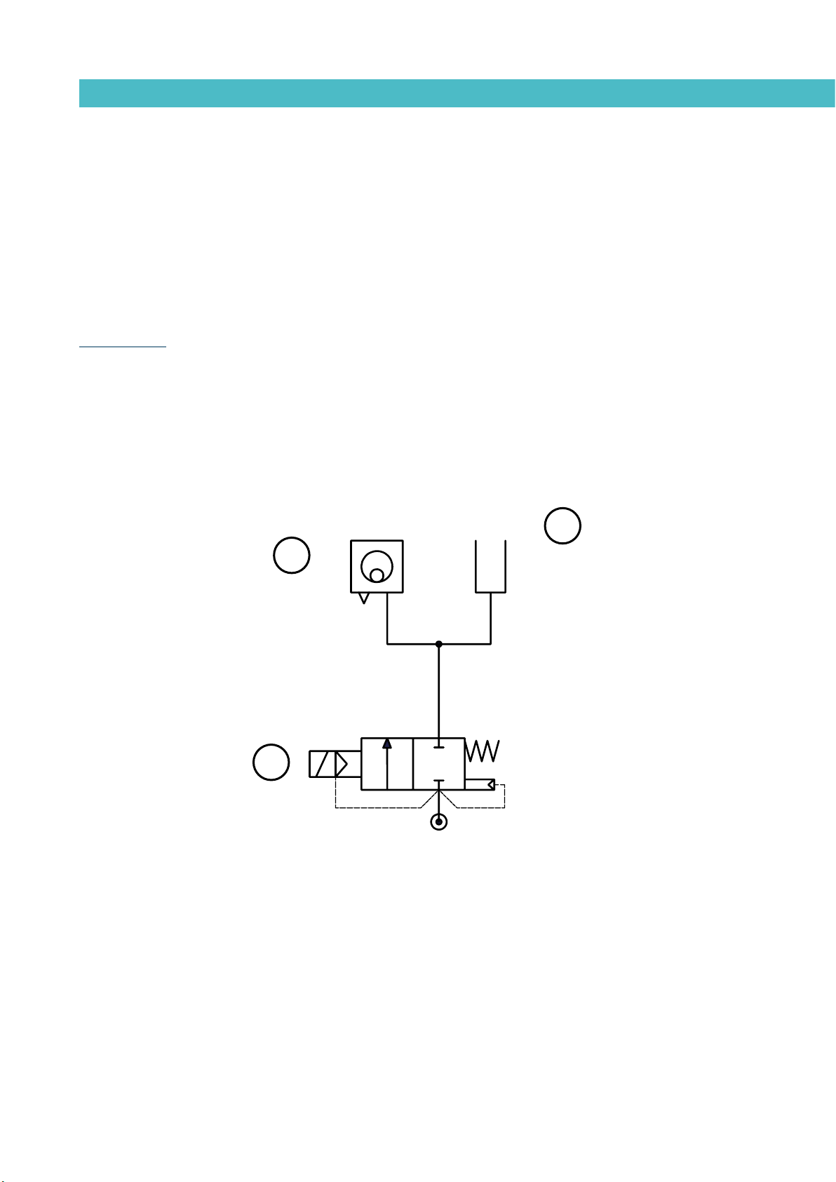
MA-5094-E MICRON MOD ADHESIVE MELTER MANUALPNEUMATIC DIAGRAM
9. PNEUMATIC DIAGRAM
Electro-pneumatic diagram for automatic feeder system
Component list
- 1 Solenoid valve 2/2. 24VDC 10W
- 2 Pneumatic vibrator
- 4 Output air. Venturi system
PNEUMATIC VIBRATOR
2
SOLENOID VALVE 24VDC
1
3
OUTPUT AIR
VENTURI SYSTEM
DRY, FILTERED AND NON LUBRICATED AIR
MAX. 6 BAR
9-1
Page 90
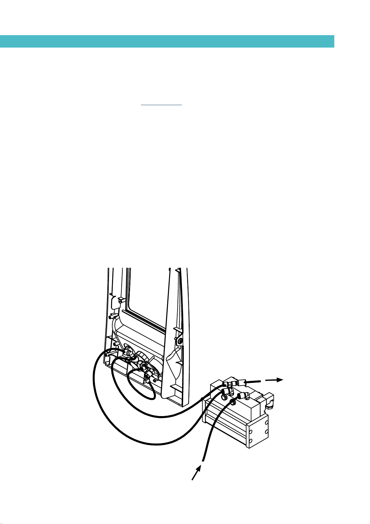
PNEUMATIC DIAGRAMFOCKE MELER GLUING SOLUTIONS
INSTRUCCION DE MONTAJE
MICRON
DENOMINACION/DENOMINATION
TITULO/TITLENº DE HOJAS
REFERENCIA/REFERENCE
IM0004
EDICION
NEUMATICA CILINDRO PEQUEÑO
2
INSTALACION NEUMATICA PARA EL GRUPO PEQUEÑO
Pneumatic connection for 7 cm3/stroke PUMP
Components list
- 1 Inlet filter (filtering disk)
- 2 Solenoid valve 3/2 manual override (230V 50 Hz 1.5VA)
- 3 Pressure regulator 1-8 bar
- 4 Pressure gauge 0-10 bar
- 5 Pneumatic valve 5/2
- 6 Differential valve
- 7 Pneumatic cylinder double acting double chamber
Ø50x50 (7cm3/stroke pump)
- 8 Exhaust port filter
- 9 Pressure discharge valve
PRESSURE
REGULATOR
TO PRESSURE DISCHARGE
VALVE
9-2
PRESSURE
GAUGE
PNEUMATIC UNIT
AIR INPUT MAX. 6 bar
Page 91

Pneumatic diagram for 7 cm3/stroke PUMP
GRUPO 7cc
MA-5094-E MICRON MOD ADHESIVE MELTER MANUALPNEUMATIC DIAGRAM
9-3
Page 92
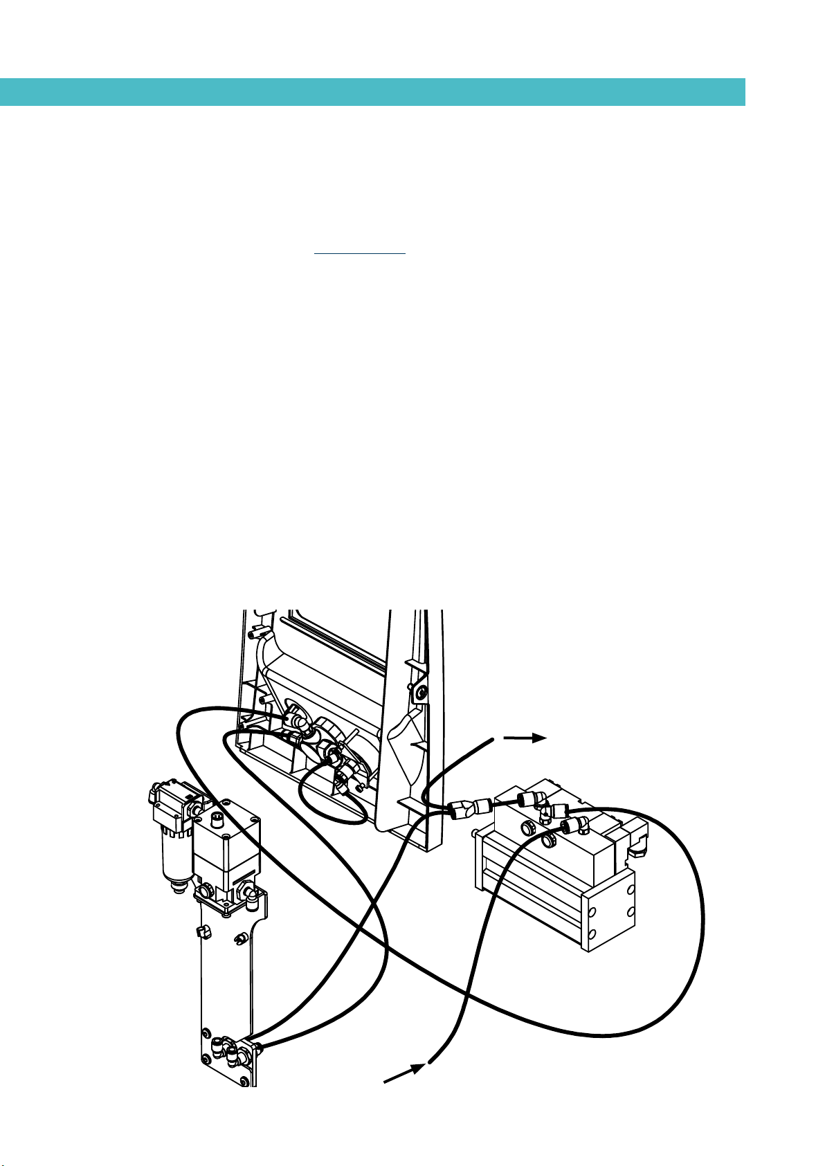
INSTRUCCION DE MONTAJE
DENOMINACION/DENOMINATION
TITULO/TITLEN
º DE HOJAS
FECHA/DATE
6/06/07
REFERENCIA/REFERENCE
IM0004
EDICION
2
VP CON GRUPO NEUMATICO 7cc
Electro-pneumatic connection with pressure regulator VP. 7 cm3/stroke PUMP
Components list
- 1 Inlet filter (filtering disk)
- 2 Solenoid valve 3/2 manual override (230V 50 Hz 1.5VA)
- 3 Pressure regulator 1-8 bar
- 4 Pressure gauge 0-10 bar
- 5 Pneumatic valve 5/2
- 6 Differential valve
- 7 Pneumatic cylinder double acting double chamber
Ø50x50 (7cm3/stroke pump)
PNEUMATIC DIAGRAMFOCKE MELER GLUING SOLUTIONS
PRESSURE
REGULATOR
- 8 Exhaust port filter
- 9 Pressure discharge valve
- 10 Air filter 5µ
- 11 Pressure regulator (proportional valve)
TO PRESSURE DISCHARGE
VALVE
PRESSURE
GAUGE
9-4
VP VALVE
PNEUMATIC UNIT
AIR INPUT MAX. 6 bar
Page 93

MA-5094-E MICRON MOD ADHESIVE MELTER MANUALPNEUMATIC DIAGRAM
06.03.2012
Electro-pneumatic diagram with pressure regulator VP. 7 cm3/stroke PUMP
9-5
Page 94

PNEUMATIC DIAGRAMFOCKE MELER GLUING SOLUTIONS
This page is intentionally left blank.
9-6
Page 95

MA-5078-E MICRON MOD ADHESIVE MELTER MANUALSPARE PARTS LIST
10. SPARE PARTS LIST
The list of the most common spare parts for Micron MOD machines appears in
this section, providing a quick and reliable guide to choosing them.
The spare parts are grouped together naturally, in the same way as they are
located in the melters.
As a visual aid, drawings of the parts are included and are numbered to help
identify them in the list. For further information about the content of the spare
parts, click on the number of the spare part.
10-1
Page 96

FOCKE MELER GLUING SOLUTIONS
SPARE PARTS LIST
This page is intentionally left blank.
10-2
Page 97
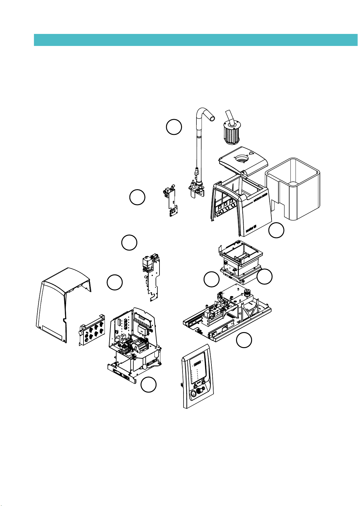
SUCTION TUBE AND
VALVE ASSEMBLY
E
CHASSIS ASSEMBLY
MA-5078-E MICRON MOD ADHESIVE MELTER MANUALSPARE PARTS LIST
F
WARNING LIGHT
H
AND VP-200 SYSTEM
F
ELECTRIC/
ELECTRONIC
ASSEMBLY
G
ELECTRIC/ELECTRONIC ASSEMBLY
B
DISTRIBUTOR
UNIT
A
TANK ASSEMBLY
PUMP
C
ASSEMBLY
D
PNEUMATIC UNIT
10-3
Page 98
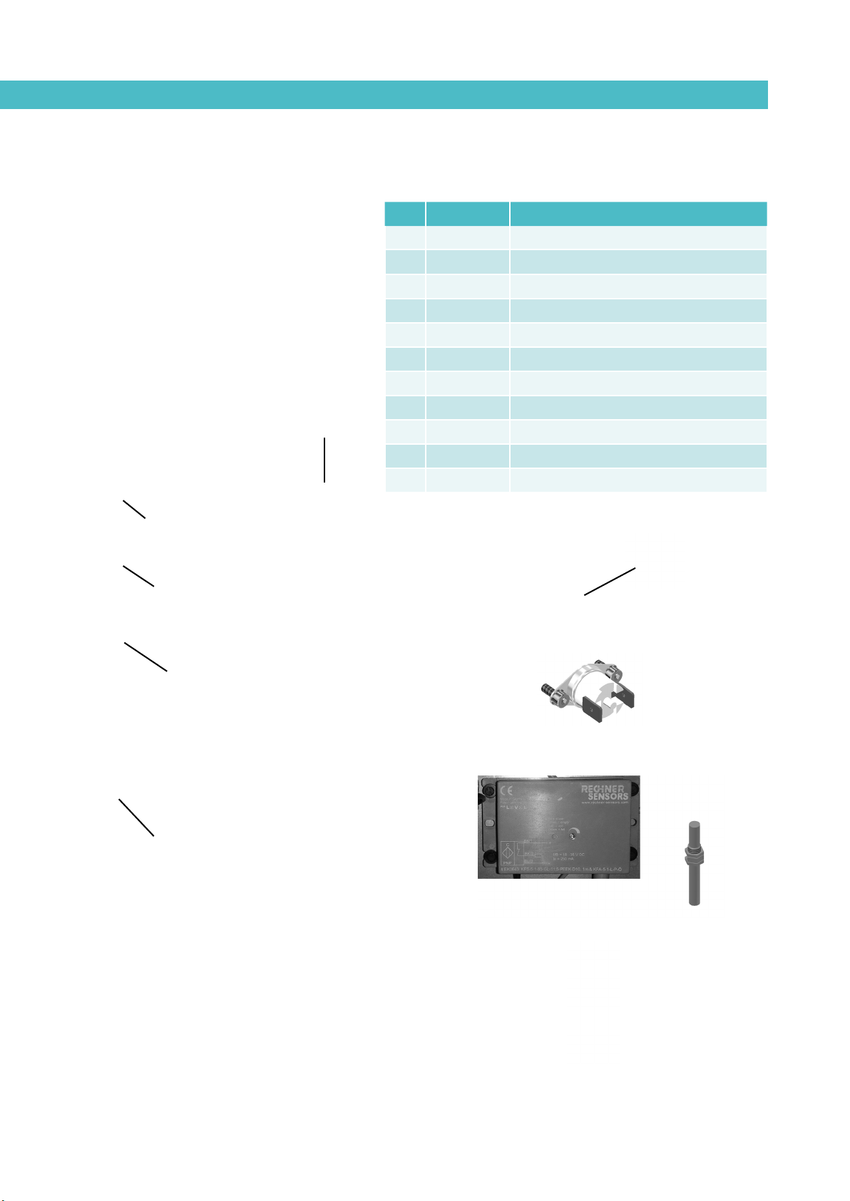
FOCKE MELER GLUING SOLUTIONS
879
2
453
1
6
10
SPARE PARTS LIST
A. TANK ASSEMBLY
Nº Ref. Description
1 150117000 Complete tank assembly 230V
2 150115760 PTFE coated tank 230V
3 150115780 Inlet tank
4 150115790 Insulation mantle inlet tank
5 150113410 Tank insulation mantle
6 150115770 Magnetic detector closed lid
7 10030007 Current connection strip
8 150114510 Safety thermostat, up to 230°C
9 150115890 Capacitive level sensor (amplifier and probe)
10 150022640 Tank sensor Pt100
10 150022650 Tank sensor Ni120
10-4
Page 99
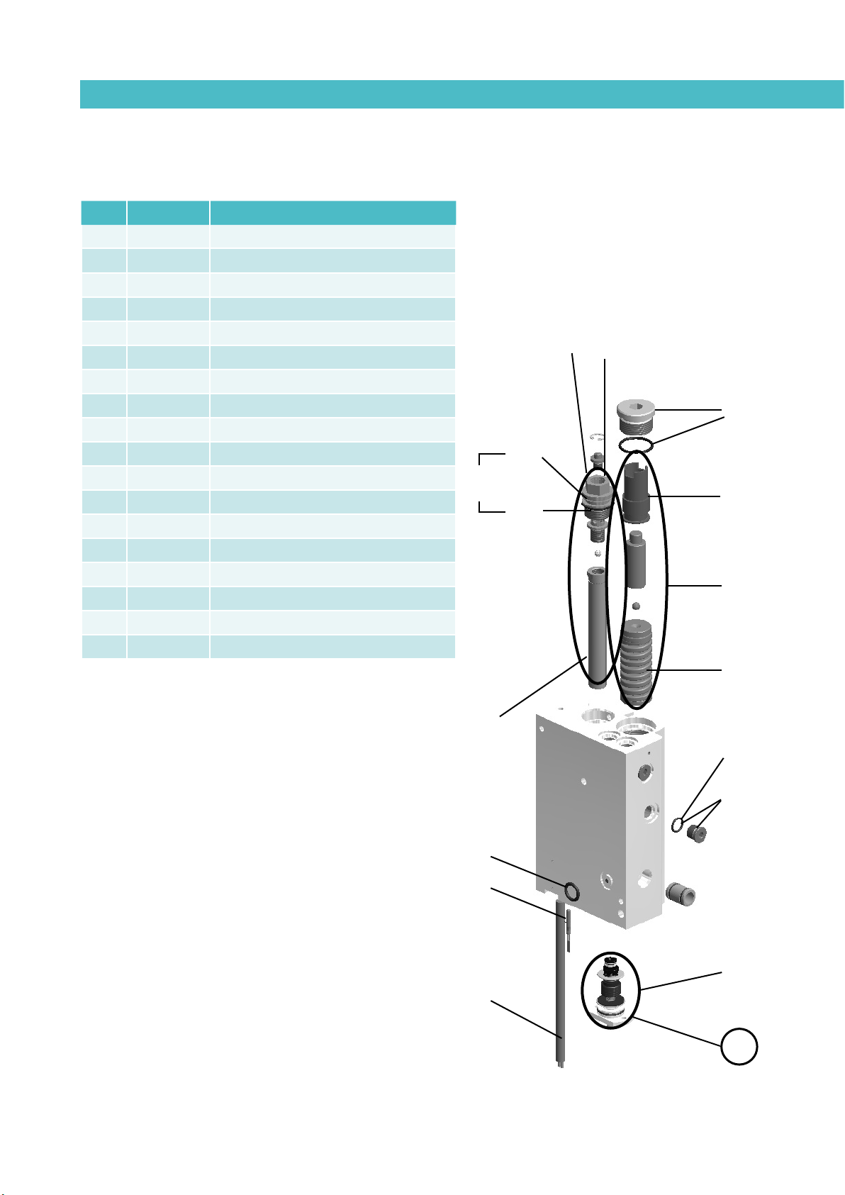
B. DISTRIBUTOR UNIT
6
5
6.1
7
7.1
3.3
4.2
4
4.1
3.2
1
2
3.4
8
3.1
3
3.5
Nº Ref. Description
1 150026350 Heating element 300 W
2 10120032 Tank-distributor seating o-ring
3 150113210 Distributor filter assembly
3.1 150114390 Filter head with purger
3.2 150029250 Filter mesh
3.3 150029260 O-ring 23X3
3.4 150116050 O-ring 29.87 X 1.78
3.5 150113260 O-rings filter assembly kit
4 150021820 Compensation valve assembly
4.1 150021830 Compensation valve piston/plunger assembly
4.2 10100096 Compensation valve spring
5 150022110 Compensation valve plug with O-ring
MA-5078-E MICRON MOD ADHESIVE MELTER MANUALSPARE PARTS LIST
6 150024750 Depressurisation valve assembly
6.1 150024760 Pressure discharge valve o-rings
7 10100082 Pump plug with o-ring
7.1 10100083 Pump o-ring
8 150113050 Sensor Pt100
8 150114540 Sensor Ni120
10-5
Page 100
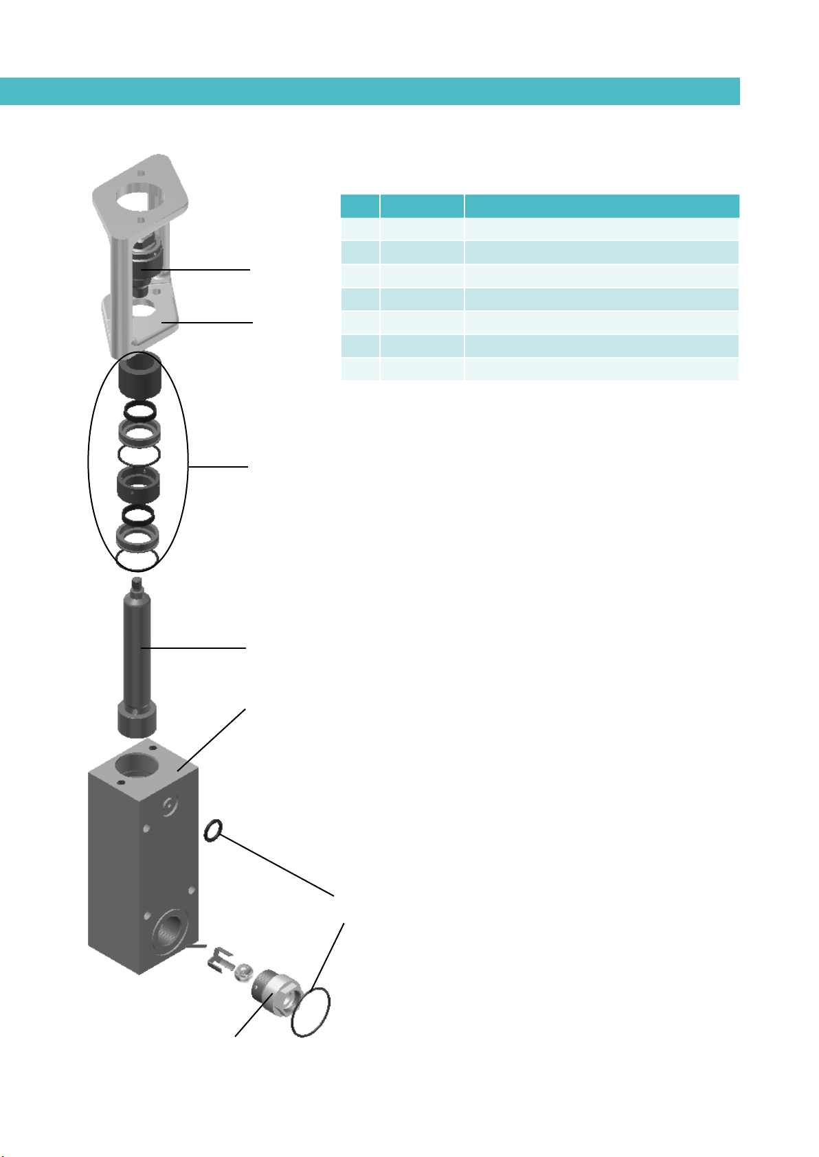
FOCKE MELER GLUING SOLUTIONS
5
1
7
4
2
3
6
SPARE PARTS LIST
C. PUMP ASSEMBLY
Nº Ref. Description
1 150113550 7cc pump body with braces and fittings
2 10100011 Pump shaft 7cc
3 150113570 Tank-pump-distributor seating O-ring kit
4 150113530 7cc pump guide bushing kit
5 150020590 Short ball and socket joint for pump shaft activator
6 150113580 Pump holding support 7cc
7 150024970 Inlet valve fitting micron pump 7cc
10-6
 Loading...