

Page 1
1-4
FUNCTION
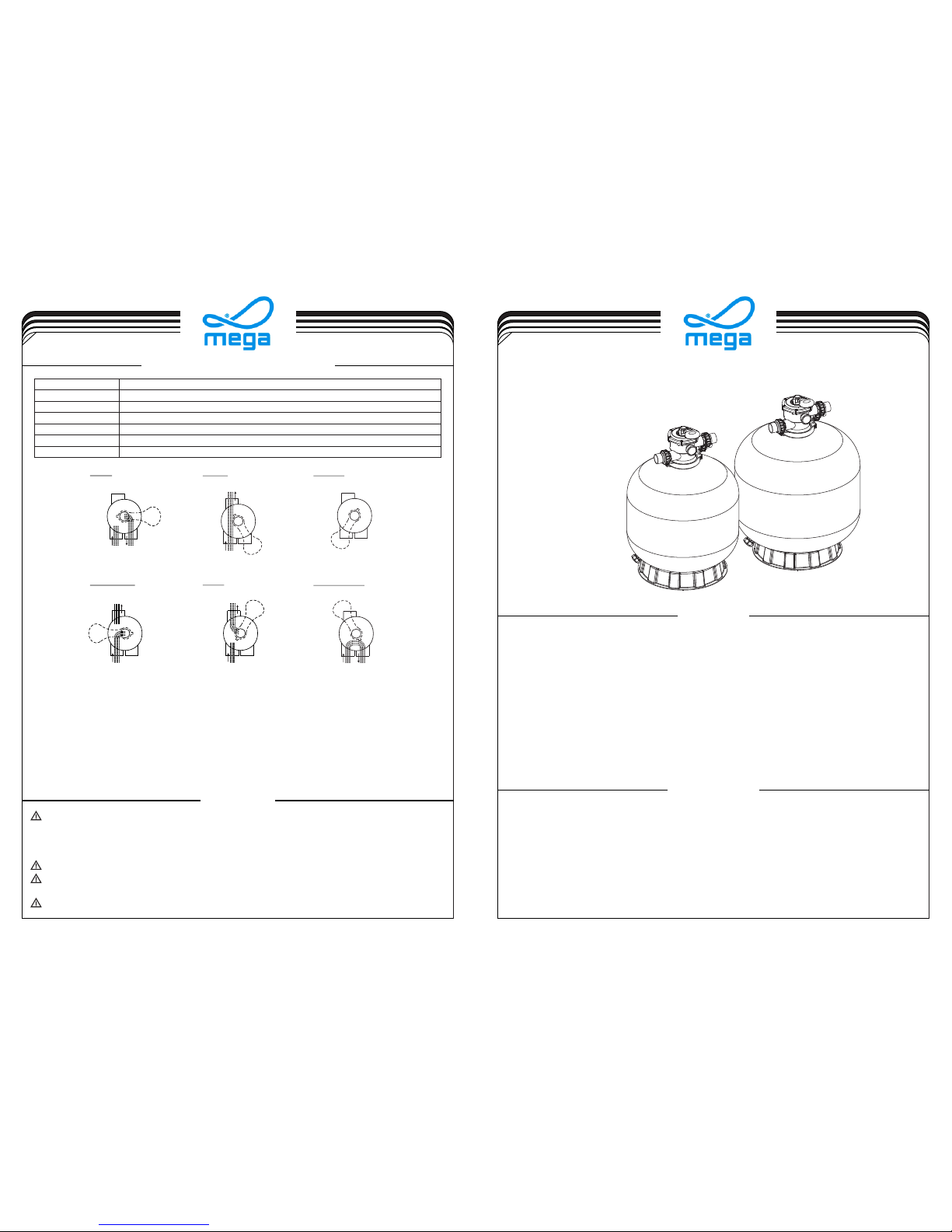
INSTALLATION
(Link by Clamp type Valves)
Models: V400 V450 V500 V650 V700V350 / / / / /
WARNING
4-4
By-passes filter for circulating water to pool
Used after backwash to flush dirt from valve
Cleaning Filter by reversing the flow
By-passes filter, used for vacuuming to waste or lowering water level
CLOSED Shuts off all flow to filter or pool
RECIRCULATE
WASTE
RINSE
BACKWASH
FILTER
Valve Position
Normal Filtration and Vacuuming
Function
EMFI16030750
FUNCTIONS OF VALVE POSITIONS
WASTE
FILTER
BACKWASH
RINSE
WASTE
RECIRCULATE
CLOSED
WASTE WASTE
WASTE WASTE WASTE
IN FLOW
OUT FLOW
IN FLOW
OUT FLOW
IN FLOW
OUT FLOW
IN FLOW
OUT FLOW
IN FLOW
OUT FLOW
IN FLOW
OUT FLOW
GENERAL
1) Pipe tap boss provided for optional influent pressure gauge.
2) SERVICING VALVE( Stop pump,close gate valve in suction&discharge before proceeding):
a) Set handle in filter position. b) Remove cover screws. c) Lift cover and key assembly out.
TO ASSEMBLE:
1) Place valve key so that wedge opening is at TOP port (handle in Filter psn.). Flat edge of cover screw lug should
align with flat edge of body screw lug.
2) Position cover O'Ring.
3) Secure assembly to body with cover screws. Tighten cover screws evenly and alternately. Do not over-tighten.
The filter uses special filter sand to remove dirt particles from pool water. The filter sand is loaded into the filter tank and
functions as a permanent dirt removing media. When the control valve is in the FILTER position, the pool water which
contains suspended dirt particles, is pumped through your piping system and is automatically directed by the
patented filter control valve to the top of the filter tank. As the pool water is pumped through the filter, dirt particles are
trapped by the sand bed, and filtered out. The cleaned pool water is returned from the bottom of the filter tank,
through the control valve and back to the pool through the piping system. This entire sequence is continuous and
automatic. It provides for total recirculation of pool water through your filter and piping system.
After a period of time, the accumulated dirt in the filter causes a resistance to flow, and the flow diminishes. This means
it is time to clean your filter. With the control valve in the BACKWASH position, the water flow is automatically reversed
through the filter so that it is directed to the bottom of the tank, up through the sand, flushing the previously trapped dirt
and debris out the waste line. Once the filter is back-washed of dirt, set control valve to RINSE position and run pump for
about 1/2 to 1 minute, and then set the control valve in the FILTER position, to resume normal filtering.
NOTE: Turn pump off before changing valve position.
Only simple tools (screwdriver and wrenches), plus pipe sealant for plastic adapters, are required to install and service the
filter.
1) The filter should be placed on a level concrete slab, very firm ground, or equivalent. The filter should be placed
2) Loading the sand media. Filter sand media is loaded through the top opening of the filter.
a) Loosen the flange clamp and remove filter control valve (if previously installed).
b) Cap internal pipe with plastic cap to prevent sand from entering it.
c) We recommend filling the tank approximately 1/2 way with water to provide a cushion effect when the filter sand is
poured in. This helps protect the under-drain laterals from excessive shock.
d) Carefully pour in correct amount and grade of filter sand. (Be sure center pipe remains centered in opening.) Sand
surface should be leveled and should come to about the middle of the filter tank. Remove plastic cap from internal
pipe.
THIS FILTER OPERATES UNDER HIGH PRESSURE. WHEN ANY PART OF THE CIRCULATING SYSTEM
(e.g., CLAMP, PUMP, FILTER, VALVES, ETC.) IS SERVICED, AIR CAN ENTER THE SYSTEM AND
BECOME PRESSURIZED . PRESSURIZED AIR CAN CAUSE THE LID OR VALVE TO BE BLOWN OFF
WHICH CAN RESULT IN SEVERE INJURY, DEATH, OR PROPERTY DAMAGE.
TURN PUMP OFF BEFORE CHANGING VALVE POSITION.
TO PREVENT DAMAGE TO THE PUMP AND FOR PROPER OPERATION OF THE SYSTEM, CLEAN
PUMP STRAINER AND SKIMMER BASKETS REGULARLY.
DO NOT UNSCREW SCREWS OF FLANGE CLAMP WHILE PUMP IS RUNNING.
Page 2
17
18
19
20
21
13
14
15
16
6
12
1
2
3
4
5
7
8
9
10
11
17
18
19
22
21
23
24
25
26
B
A
2-4
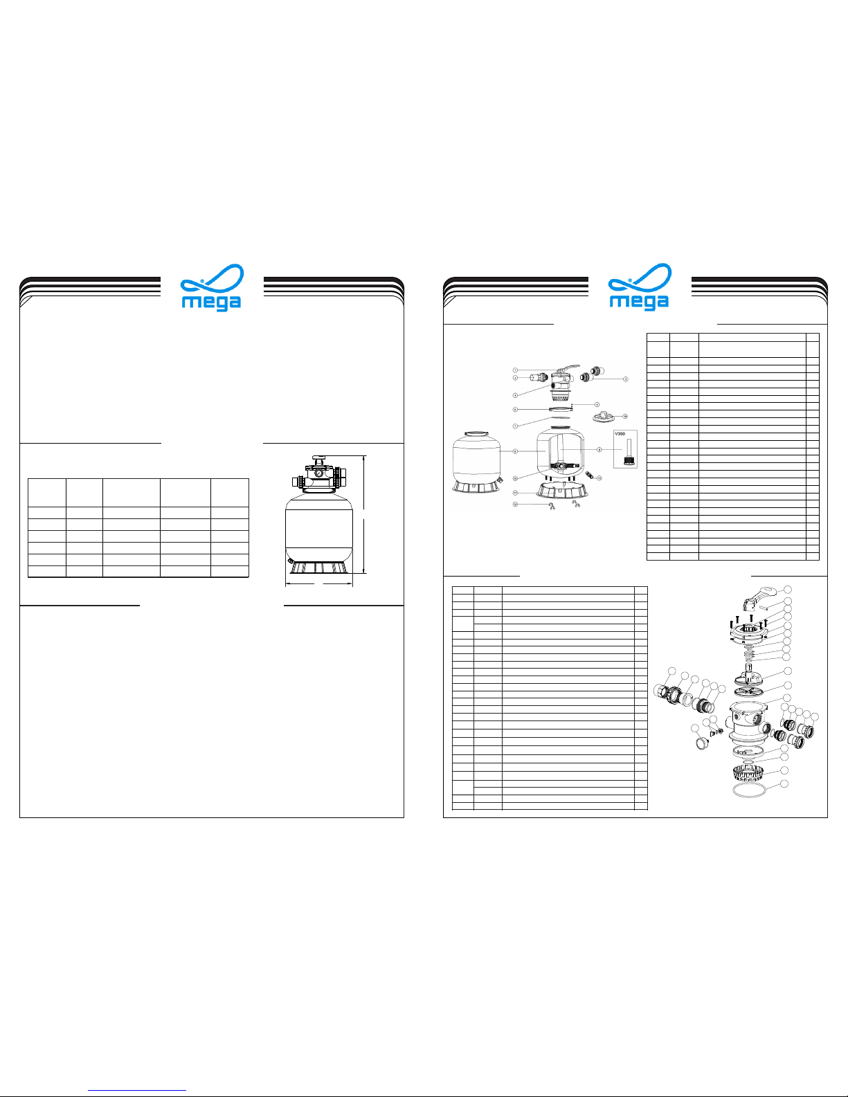
MAIN DIMENSION
REPLACEMENT PARTS OF FILTER
3-4
1) Make sure the correct amount of filter media sand is located in the tank and all connections have been
connected and secured.
2) Depress control valve handle and rotate to BACKWASH position. (To prevent damage to control valve seal, always
depress handle before turning.)
3) Prime and start pump according to pump instructions (be sure all suction and return lines are open), allowing the
filter tank to fill with water. Once water is flowing out of the waste line, run the pump for at least 1 minute. The initial
back-washing of the filter is recommended to remove any impurities or fine sand particles in the sand media.
4) Turn pump off and set valve to RINSE position. Start pump and operate until water in sight glass is clear, about 1/2 to
1 minute. Turn pump off and set valve to FILTER position and restart pump. The filter is now operating in the normal
filter mode, filtering dirt particles from the pool water.
5) Adjust pool suction and return valves to achieve desired flow. Check system and filter for water leaks and tighten
connections, bolts, nuts, as required.
6) Note the initial pressure gauge reading when the filter is clean. (It will vary from pool to pool depending upon the
pump and general piping system.) As the filter removes dirt and impurities from the pool water, the accumulation
of dirt in the filter will cause the pressure to rise and diminish the water flow. When the pressure gauge reading is 1.5
bar, higher than the initial "clean" pressure you noted, it is time to backwash the filter (see BACKWASH under filter
and control valve functions).
INSTALL/START-UP OF FILTER
DIMENSION TABLE
757
726
A
V400
V350
355
410
B
Model
High
Diameter
mm
mm
814V450 455
845V500 535
950V650 635
Inch
Valve Port
Size
Sand
kg
35
20
45
85
145
1.5"
1.5"
1.5"
1.5"
1.5"
1020
V700
710
210
1.5"
REPLACEMENT PARTS OF MULTIPORT VALVE
Key No .
Part N o.
Prod uct Des cript ion
Qty
1
0101 3003
Hand le(Bi g)
120301 8008
Pin fo r Handl e13
0118 1001
Wash er for Ha ndle
1
4
8928 1203
M6×2 5 Screw w ith Nut f or Camb er Lid
6
8928 0107
M6×3 0 Screw w ith Nut f or Stan dard Li d
650101 3004
1.5" Top Mount Va lve Sta ndard L id (Bl ack)
160201 1002
O-Ri ng for 1. 5" Valve Lid
170118 1002
Wash er for Sp ring
1
8
0301 4001
Spri ng for 1. 5" Top M ount Va lve
190201 1022
O-Ri ng for 1. 5" Valve Rot or
2100102 1001
1.5" V alve Ro tor wit h O-Ri ng
1
11
0231 1002
Spid er Gask et112
0101 3007
1.5" Top Mount Va lve Bot tom Bod y Clamp (blac k)
1130101 3011
1.5" D iffus er114
0201 1001
O-Ri ng for Di ffuse r
1150101 3012
1.5" Top Mount Va lve Ove r Drain D iffus er
1160201 1134
O-Ri ng
1
17
0202 0013
O-Ri ng for 1. 5"Conne ctor
3
18
0101 3015
1.5" Connecto r (bla ck)
3190201 1003
O-Ri ng for 1. 5"Union
3
20
0117 1153
1.5" Union (A/ E)
2210101 3017
1.5" Union Nut ( blac k)
3
22
0104 1002
1.5" Union With S ight Gl ass (s hort)
1
23
0117 2026
1.5" Union With S ight Gl ass Hol der
1
24
0111 1048
Conn ector f or pres sure ga uge/s toppe r
1
0201 1139
O-Ri ng125
8902 1303
Drai n Plug wi th O-ri ng
1
26
0601 1029
Oil Pr essur e Gauge W ith O-r ing (4 0psi)
1
3) Assemble filter control valve into the filter tank.
a) Insert filter control valve (with O'ring in place) into the tank neck, taking care that the center pipe slips into the
hole in the bottom of the valve.
b) Place two plastic clamps around valve flange and tank flange and tighten just enough so that the valve may
be rotated on tank for final positioning.
c) Carefully screw pressure gauge (with O'ring in place) into tapped hole in valve body. Do not over-tighten.
d) Connect pump to control valve opening marked PUMP. After connections are made, tighten valve flange
clamps with screwdriver, tapping around clamp with screwdriver handle to help seat valve flange clamp.
4) Make return to pool pipe connection to control valve opening marked RETURN and complete other necessary
plumbing connections, suction lines to pump, waste, etc.
5) Make electrical connections to pump per pump instructions.
6) To prevent water leakage, make sure all pipe connections are tight.
NOTE: During initial clean-up of the pool water it may be necessary to backwash frequently due to the unusually
heavy initial dirt load in the water.
Key No .
Part N o.
Desc ripti on
Qty
1
8828 0150B
6 Way 1. 5" Valv e with 1. 5" unio n set x 3 and
pres sure ga uge (Bl ack)
1
2
8928 0101B
1.5" u nion wi th sigh t glass w ith O-r ing (Bl ack)
1
3
8928 0102B
1.5" u nion se t with O- ring (B lack)
2
4
0602 1013
Plas tic Pre ssure G auge wi th O-Ri ng
1
4
0111 1048
Conn ector f or Pres sure Ga uge/S toppe r
158901 0119
M6*5 0 Screw s with Nu t
2
6
0127 1010
Clam p Lock
2
7
0201 1134
O-Ri ng for Fi lter Ne ck
1
8
8901 0114
V350 F ilter t ank18
8901 0113
V400 F ilter t ank
1
8
8901 0112
V450 Filte r Tank18
8901 0111
V500 F ilter t ank18
8901 0110
V650 F ilter t ank18
8901 0109
V700 F ilter t ank19
8901 0106
V350 L atera l Assem bly wit h Cente r Pipe
198901 0118
V400 S tandp ipe wit h hub
198901 0105
V450 L atera l Assem bly wit h Cente r Pipe
198901 0104
V500 L atera l Assem bly wit h Cente r Pipe
1
9
8901 0103
V650 L atera l Assem bly wit h Cente r Pipe
198901 0102
V700 S tandp ipe wit h Hub
1
10
0117 2007
Late rals( 115mm )
8
10
0117 2008
Late rals (1 26mm)
8110111 1052
V/P3 50 Filt er Base
1110111 1059
16-2 1inch F ilter B ase
1
11
0111 1062
21-2 8" Filt er Base f or V500 / V650/ V 700
1120118 1052
Fast ener fo r Filte r Base
4
13
8901 0107
Wate r Drain S et
1140101 5006
Sand D ivert er (Bla ck) for 1 .5"
1
Notes:10* 01172007 is laterals (115mm) for V350-V450
10* 01172008 is laterals (126mm) for V500-700
Page 3

1-4
Models: V700(B) / V800 V900 V1000 V1200 / / /
(Link by Nuts type Valves)
EMFI16 030752
FUNCTION
INSTALLATION
The filter uses special filter sand to remove dirt particles from pool water. The filter sand is loaded into the filter tank and
functions as a permanent dirt removing media. When the control valve is in the FILTER position, the pool water which
contains suspended dirt particles, is pumped through your piping system and is automatically directed by the
patented filter control valve to the top of the filter tank. As the pool water is pumped through the filter, dirt particles are
trapped by the sand bed, and filtered out. The cleaned pool water is returned from the bottom of the filter tank,
through the control valve and back to the pool through the piping system. This entire sequence is continuous and
automatic. It provides for total recirculation of pool water through your filter and piping system.
After a period of time, the accumulated dirt in the filter causes a resistance to flow, and the flow diminishes. This means
it is time to clean your filter. With the control valve in the BACKWASH position, the water flow is automatically reversed
through the filter so that it is directed to the bottom of the tank, up through the sand, flushing the previously trapped dirt
and debris out the waste line. Once the filter is back-washed of dirt, set control valve to RINSE position and run pump for
about 1/2 to 1 minute, and then set the control valve in the FILTER position, to resume normal filtering.
NOTE: Turn pump off before changing valve position.
Only simple tools (screwdriver and wrenches), plus pipe sealant for plastic adapters, are required to install and service the
filter.
1) The filter should be placed on a level concrete slab, very firm ground, or equivalent. The filter should be placed
2) Loading the sand media. Filter sand media is loaded through the top opening of the filter.
a) Loosen the flange clamp and remove filter control valve (if previously installed).
b) Cap internal pipe with plastic cap to prevent sand from entering it.
c) We recommend filling the tank approximately 1/2 way with water to provide a cushion effect when the filter sand is
poured in. This helps protect the under-drain laterals from excessive shock.
d) Carefully pour in correct amount and grade of filter sand. (Be sure center pipe remains centered in opening.) Sand
surface should be leveled and should come to about the middle of the filter tank. Remove plastic cap from internal
pipe.
WARNING
4-4
By-passes filter for circulating water to pool
Used after backwash to flush dirt from valve
Cleaning Filter by reversing the flow
By-passes filter, used for vacuuming to waste or lowering water level
CLOSED Shuts off all flow to filter or pool
RECIRCULATE
WASTE
RINSE
BACKWASH
FILTER
Valve Position
Normal Filtration and Vacuuming
Function
FUNCTIONS OF VALVE POSITIONS
WASTE
FILTER
BACKWASH
RINSE
WASTE
RECIRCULATE
CLOSED
WASTE WASTE
WASTE WASTE WASTE
IN FLOW
OUT FLOW
IN FLOW
OUT FLOW
IN FLOW
OUT FLOW
IN FLOW
OUT FLOW
IN FLOW
OUT FLOW
IN FLOW
OUT FLOW
GENERAL
1) Pipe tap boss provided for optional influent pressure gauge.
2) SERVICING VALVE( Stop pump,close gate valve in suction&discharge before proceeding):
a) Set handle in filter position. b) Remove cover screws. c) Lift cover and key assembly out.
TO ASSEMBLE:
1) Place valve key so that wedge opening is at TOP port (handle in Filter psn.). Flat edge of cover screw lug should
align with flat edge of body screw lug.
2) Position cover O'Ring.
3) Secure assembly to body with cover screws. Tighten cover screws evenly and alternately. Do not over-tighten.
THIS FILTER OPERATES UNDER HIGH PRESSURE. WHEN ANY PART OF THE CIRCULATING SYSTEM
(e.g., CLAMP, PUMP, FILTER, VALVES, ETC.) IS SERVICED, AIR CAN ENTER THE SYSTEM AND
BECOME PRESSURIZED . PRESSURIZED AIR CAN CAUSE THE LID OR VALVE TO BE BLOWN OFF
WHICH CAN RESULT IN SEVERE INJURY, DEATH, OR PROPERTY DAMAGE.
TURN PUMP OFF BEFORE CHANGING VALVE POSITION.
TO PREVENT DAMAGE TO THE PUMP AND FOR PROPER OPERATION OF THE SYSTEM, CLEAN
PUMP STRAINER AND SKIMMER BASKETS REGULARLY.
DO NOT UNSCREW SCREWS OF FLANGE CLAMP WHILE PUMP IS RUNNING.
Page 4

B
A
MAIN DIMENSION
3) Assemble filter control valve into the filter tank.
a) Insert filter control valve (with O'ring in place) into the tank neck, taking care that the center pipe slips into the
hole in the bottom of the valve.
b) Place two plastic clamps around valve flange and tank flange and tighten just enough so that the valve may
be rotated on tank for final positioning.
c) Carefully screw pressure gauge (with O'ring in place) into tapped hole in valve body. Do not over-tighten.
d) Connect pump to control valve opening marked PUMP. After connections are made, tighten valve flange
clamps with screwdriver, tapping around clamp with screwdriver handle to help seat valve flange clamp.
4) Make return to pool pipe connection to control valve opening marked RETURN and complete other necessary
plumbing connections, suction lines to pump, waste, etc.
5) Make electrical connections to pump per pump instructions.
6) To prevent water leakage, make sure all pipe connections are tight.
REPLACEMENT PARTS OF MULTIPORT VALVE
DIMENSION TABLE
2-4
3-4
1300
1200
A
V900
V800 800
900
B
Model
High Diameter
mm
mm
1400V1000 1000
1600V1200 1200
Inch
Valve Port
Size
Sand
kg
470
355
620
860
2"
2"
2"
2"
1092V700(B) 723
215
2"
Key No .
Part N o.
Prod uct Des cript ion
Qty
1
0101 3003
Hand le (Big )
120301 8008
Pin fo r Handl e13
0118 1027
Wash er for Ha ndle
1
4
8928 0301
M6*3 2 Screw w ith Nut
1050101 3019
2.0" Top Mou nt Valv e Stand ard Lid ( Black )
1
6
0301 4014
Spri ng for 2. 0" Top Mo unt Val ve
170201 1006
O-Ri ng for 2. 0" Top Mo unt Val ve Lid
180201 1022
O-Ri ng for 2. 0" Top Mo unt Val ve Roto r
2
9
0118 1002
Wash er for Sp ring
2100102 1002
2.0" V alve Ro tor
1
11
0231 1003
Spid er Gask et
1120101 3027
2.0" T op Moun t Valve B ottom B ody (bl ack)
1
13
0101 3029
2.0" W ater Tu be
1140101 3030
2.0" D iffus er
1
15
0201 1005
O-Ri ng for Di ffuse r
1160202 0016
O-Ri ng for Co nnect or
6170101 3031
2.0" Conne ctor wi th Exte rnal Th read (B lack)
3
18
0117 1154
2.0" Union A dapto r
3
19
0101 3032
2.0" Union N ut (Bla ck)
3208928 0104
Sigh t Glass w ith O-R ing
1210111 1048
Conn ector f or Pres sure Ga uge/S toppe r
1
22
8902 1303
Drai n Plug wi th O-ri ng
1230601 1029
Oil Pr essur e Gauge W ith O-r ing (40 psi)
1
1) Make sure the correct amount of filter media sand is located in the tank and all connections have been
connected and secured.
2) Depress control valve handle and rotate to BACKWASH position. (To prevent damage to control valve seal, always
depress handle before turning.)
3) Prime and start pump according to pump instructions (be sure all suction and return lines are open), allowing the
filter tank to fill with water. Once water is flowing out of the waste line, run the pump for at least 1 minute. The initial
back-washing of the filter is recommended to remove any impurities or fine sand particles in the sand media.
4) Turn pump off and set valve to RINSE position. Start pump and operate until water in sight glass is clear, about 1/2 to
1 minute. Turn pump off and set valve to FILTER position and restart pump. The filter is now operating in the normal
filter mode, filtering dirt particles from the pool water.
5) Adjust pool suction and return valves to achieve desired flow. Check system and filter for water leaks and tighten
connections, bolts, nuts, as required.
6) Note the initial pressure gauge reading when the filter is clean. (It will vary from pool to pool depending upon the
pump and general piping system.) As the filter removes dirt and impurities from the pool water, the accumulation
of dirt in the filter will cause the pressure to rise and diminish the water flow. When the pressure gauge reading is 1.5
bar, higher than the initial "clean" pressure you noted, it is time to backwash the filter (see BACKWASH under filter
and control valve functions).
INSTALL/START-UP OF FILTER
NOTE: During initial clean-up of the pool water it may be necessary to backwash frequently due to the unusually
heavy initial dirt load in the water.
1
2
3
4
5
6
7
8
9
10
11
12
13
14
15
16
17
16
18
19
20
21
22
23
Key No .
Part N o.
Desc ripti on
Qty
1
8901 0601
Nut wi th Wash er
12
2
8828 0351B
6 Way 2" V alve wi th 2" uni on set x 3
and pr essur e gauge ( Black )
1
3
0601 1029
Maxi mum 40P SI Indi catio n, Stai nless
Stee l Casin g
1
4
8928 0103B
2.0" U nion wi th O-Ri ng (Bla ck)
3
5
8928 0104
Sigh t Glass w ith O-R ing
1
6
0201 1126
Filt er Neck G asket
1
7
8901 0612
V700 B Filte r Tank wi th Base
1
7
8901 0603
V800 F ilter T ank wit h Base
178901 0604
V900 F ilter T ank wit h Base
1
7
8901 0605
V100 0 Filte r Tank wi th Base
1
7
8901 0606
V120 0 Filte r Tank wi th Base
188901 0611
V700 B Stand pipe wi th hub
1
8
8901 0607
V800 S tandp ipe wit h Hub
1
8
8901 0608
V900 S tandp ipe wit h Hub
1
8
8901 0609
V100 0 Stand pipe wi th Hub
1
8
8901 0610
V120 0 Stand pipe wi th Hub
190117 2010
Late rals (1 85mm)
8
9
0117 2011
Late rals (2 33mm)
8
9
8901 0613
Late rals( 129mm & 1 85mm)
8
9
8901 0614
Late rals( 129mm & 2 33mm)
8
10
8901 0107
Wate r Drain S et
1110111 1062
21-2 8inch F ilter B ase
1
11
0111 2038
32-4 0 inch Fi lter Ba se
1
11
0111 2039
Base f or V120 0
1
Notes:9* 01172010 Laterals (185mm) for V700B
9* 01172011 Laterals (233mm) for V800 & V900
9* 89010613 Laterals (129mm & 185mm) for V1000
9* 89010614 Laterals (129mm & 233mm) for V1200
REPLACEMENT PARTS OF FILTER
 Loading...