

Page 1
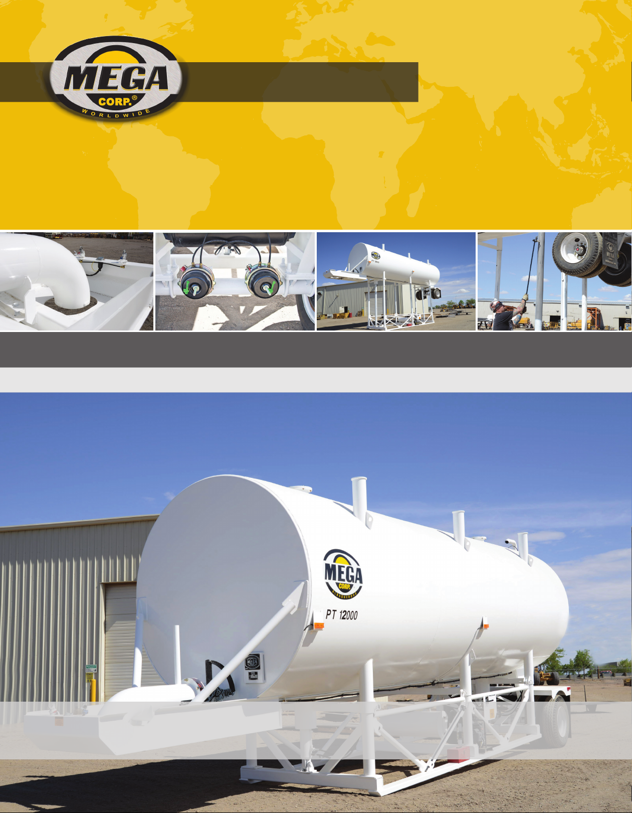
GENUINE MEGA.
MPT
MEGA PORTABLE TANK
TECHNICAL MANUAL
SPECIALTY HAULAGE SOLUTIONS FOR CONSTRUCTION AND MINING
MEGA CORP.®
700 Osuna Rd. N.E. • Albuquerque, NM 87113 • 1-800-345-8889 • 505-345-2661 • Fax 505-345-6190
www.megacorpinc.com
® MEGA Corp., Inc. All Rights Reserved
Page 2

MPT12 Manual
24 May 2017
TABLE OF CONTENTS
Page
Section 1 Definitions and Abbreviations . . . . . . . . . . . . . . . . . . . . . . . . . . . . . . . . . . . . . . . . . . . . . . . . .1-1
Section 2 System Description. . . . . . . . . . . . . . . . . . . . . . . . . . . . . . . . . . . . . . . . . . . . . . . . . . . . . . . . . . . .2-1
Section 3 Commissioning . . . . . . . . . . . . . . . . . . . . . . . . . . . . . . . . . . . . . . . . . . . . . . . . . . . . . . . . . . . . . . . 3-1
Section 4 Operation Instructions. . . . . . . . . . . . . . . . . . . . . . . . . . . . . . . . . . . . . . . . . . . . . . . . . . . . . . . . . 4-1
Section 5 Maintenance and Repair. . . . . . . . . . . . . . . . . . . . . . . . . . . . . . . . . . . . . . . . . . . . . . . . . . . . . . .5-1
Section 6 Scheduled Maintenance Inspections . . . . . . . . . . . . . . . . . . . . . . . . . . . . . . . . . . . . . . . . . . .6-1
Section 7 Recommended Support Parts. . . . . . . . . . . . . . . . . . . . . . . . . . . . . . . . . . . . . . . . . . . . . . . . . . 7-1
Section 8 Illustrated Parts Breakdown. . . . . . . . . . . . . . . . . . . . . . . . . . . . . . . . . . . . . . . . . . . . . . . . . . . .8-1
Section 9 Appendix: Installation Drawings . . . . . . . . . . . . . . . . . . . . . . . . . . . . . . . . . . . . . . . . . . . . . . .9-A
A
Page 3

MPT12 Manual
24 May 2017
TABLE OF CONTENTS
B (Blank)
Page 4
SECTION 1
Definitions and Abbreviations
Contents
MPT12 Manual
24 May 2017
Manual Usage ...................................................................1-1
Warning, Caution And Notes ......................................1-1
Use Of Shall, Will, Should And May ...........................1-1
MANUAL USAGE
This technical manual only contains information
required to safely operate and maintain the Mega
Portable Tank. If your system is not covered in this
manual please contact MEGA Corp. Product Support
at: 1-800-345-8889 or visit our website at
www.megacorpinc.com for more detailed
information.
The exact location of the hazards and description of
the hazards are reviewed in this section. All personnel
working on or operating the machine must become
familiarized with all the safety messages.
Due to the nature of these processes, ensure that all
safety information, warnings and instructions are
read and understood before any operation or any
maintenance procedures are performed. Some
procedures take place with heavy components and
at moderate heights, ensure proper safety
procedures are maintained when performing these
actions. Failure to use and maintain proper safety
equipment and procedures will cause injury, death or
damage to equipment.
Safety Messages ..............................................................1-2
Abbreviations ...................................................................1-3
MPT Overview (Typical) ................................................1-4
WARNING, CAUTION AND NOTES
The following definitions are found throughout the
manual and apply as follows:
Operating procedures and techniques, which could
result in personal injury and/or loss of life if not
carefully followed.
Operating procedures and techniques, which could
result in damage to equipment if not carefully
followed.
Operating procedures and techniques that are
considered essential to emphasize.
USE OF SHALL, WILL, SHOULD AND MAY
Shall and Will – Used when application of a
procedure is mandatory.
Should – Used when application of a procedure is
recommended.
May - Used to indicate an acceptable or suggested
means of accomplishment.
1-1
Page 5
MPT12 Manual
24 May 2017
SECTION 1
Definitions and Abbreviations
SAFETY MESSAGES
There are several specific safety messages applicable
to this machine. Some of these safety messages have
associated warning labels located on the machine.
The descriptions of the hazards and the locations (if
applicable) of their warning labels are reviewed in
this section. All personnel working on or operating
the machine must become familiarized with all the
safety messages.
Make sure that all of the safety labels are legible.
Clean or replace the safety labels if you cannot read
the words. Replace the illustrations if the illustrations
are not legible. When you clean the safety labels, use
a cloth, water and soap. Do not use solvent, gasoline
or other harsh chemicals to clean the safety labels.
Solvents, gasoline or harsh chemicals could loosen
the adhesive that secures the safety labels. Loose
adhesive will allow the safety labels to detach.
Replace any safety label that is damaged or missing.
If a safety label is attached to a part that is replaced,
install a new safety label on the replacement part.
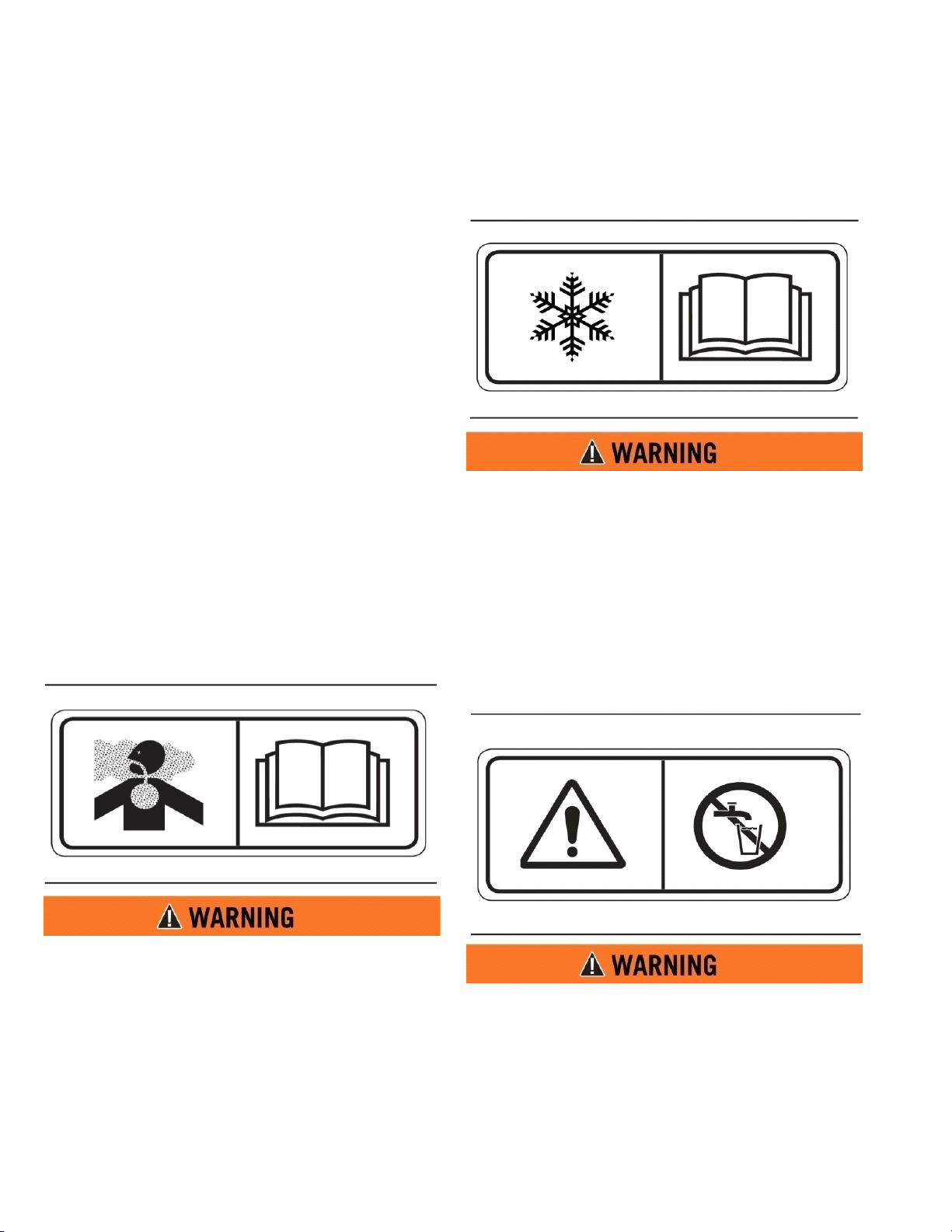
FREEZING (2)
This safety label is located on the front of the
machine, by the discharge pipe..
Drain tank, fill pipe, and drain valve in freezing
weather. Refer to the Operator and Maintenance
Manual for the procedure to follow.
TOXIC GAS HAZ ARD ( 1)
Cutting or welding operation on the inside of the
tank can cause the accumulation of toxic gases.
Read and understand instructions and warnings
in the Maintenance Manual. Failure to provide
proper ventilation or breathing apparatus while
conducting these operations may result in serious
injury or death.
NON-POTABLE (3)
This safety label is located at the rear of the tank, near
the ladder.
Water held within tank is not potable. Do not use
tank for transport of water intended for human or
animal consumption or serious injury or death
may result.
1-2
Page 6
SECTION 1
Definitions and Abbreviations
MPT12 Manual
24 May 2017
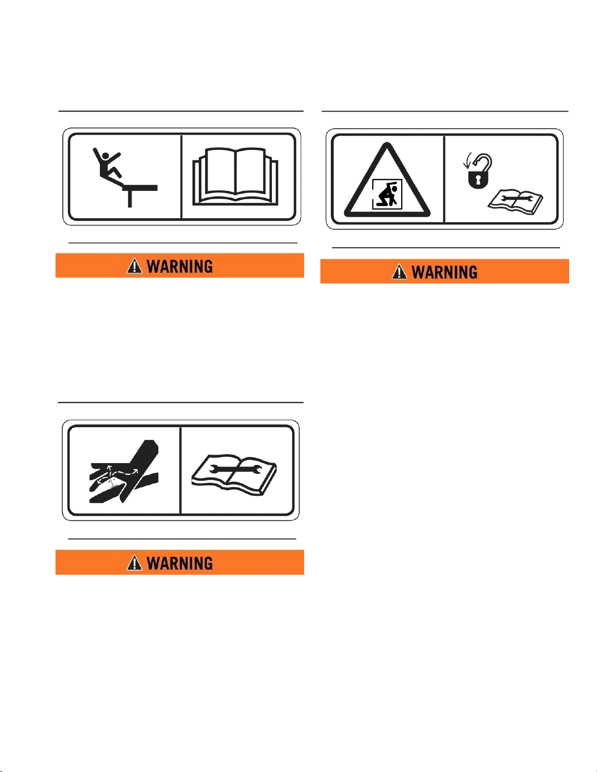
FALL HAZARD (4)
Do not walk on the top of tank without fall arrest
PPE. Serious injury or death could occur from a
fall.
HIGH PRESSURE MOTOR (5)
CONFINED SPACE (6)
Do not enter confined spaces without following
established site specific procedures. Failure to
follow proper safety procedures will result in
serious injury or death.
ABBREVIATIONS
BFV - Butterfly Valve
CCW - Counterclockwise
CW - Clockwise
FIP - Fault Isolation Procedures
Ft-lbs - Foot Pounds of Torque
GPM - Gallons per Minute
IPB - Illustrated Parts Breakdown
LT - Left (as viewed from the rear of the
vehicle looking forward)
MPT - Mega Portable Tank
n-m - Newton Meters of Torque
PSI - Pounds per Square Inch
RT - Right (as viewed from the rear of the
vehicle looking forward)
RPM - Revolutions per minute
Hydraulic motor and supply lines contain oil
under high pressure. Improper removal and
repair procedures could cause severe injury. To
remove or repair, instructions in the Maintenance
Manual must be followed.
1-3
Page 7
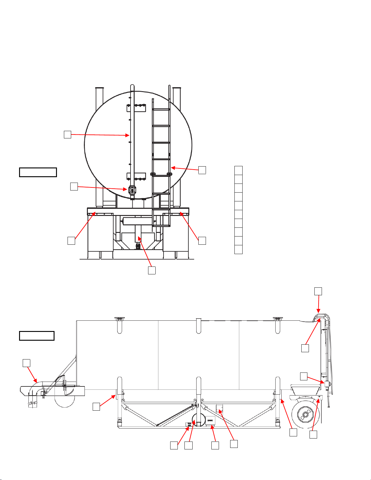
MPT12 Manual
8
1
5
2
4
6
1
HYDRAULIC CYLINDERS
2
ENGINE & HYDRAULIC PUMP
3
LEVER CONTROL SYSTEM
4
FILL PIPE
5
FILL PIPE VALVE
6
ACCESS LADDER
7
TOOL BOX
8
DISCHARGE TUBE
9
D.O.T. LIGHTS
10
HYDRAULIC TANK
REAR VIEW
SIDE VIEW
1
1
3
7
5
4
6
9 9
9
10
24 May 2017
SECTION 1
Definitions and Abbreviations
MPT OVERVIEW (TYPICAL)
1-4
Page 8
SECTION 2
System Description
Contents
MPT12 Manual
24 May 2017
Description.........................................................................2-1
MPT Tank .............................................................................2-1
Self-Raising System .........................................................2-1
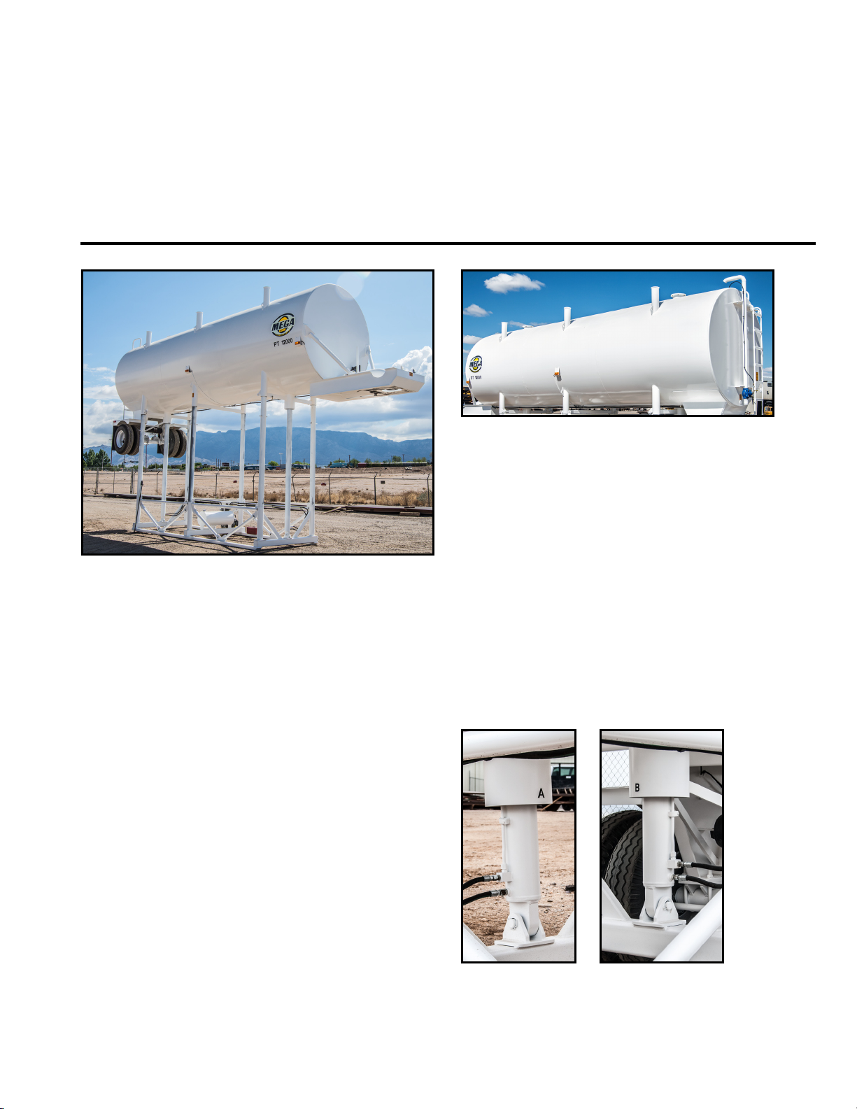
DESCRIPTION
The Mega Portable Tank (MPT) is a 12,000 gallon
platform or stand tank designed for towing with a
fifth-wheel on-highway tractor. The Mega MPT is
used to rapidly fill water distribution equipment to
maximize productivity. All Mega MPTs are selferecting by use of an engine-driven hydraulic pump
and hoist cylinders with pin locks. Mega MPTs have a
10 inch diameter discharge pipe capable of filling a
5,000 gallon tank in approximately 2 minutes. The
MPT can be filled from a municipal water source or
with other water pumping equipment. The 3” fill pipe
is equipped with an automatic shut off to prevent
overfilling.
Water Discharge System ............................................... 2-2
Axle .......................................................................................2-2
MPT TANK
The MPT tank is 2.59m (8.5 ft) in diameter, 11.13m
(36.5 ft.) in length, and has a capacity of 45.42 L
(12,000 gallons). The corners of the tank are
reinforced to provide sturdy connection to supports.
An access ladder leading to the top of the tank is
located at the rear of the trailer, and a ladder is
located inside of the tank. An 8” diameter float is
located inside of the tank for automatic fill shut-off
when the tank is full.
SELF-RAISING SYSTEM
The MPT’s self-raising system incorporates dual
hydraulic cylinders and a 6.5 horsepower engine with
a hydraulic pump.
HYDRAULIC CYLINDERS
The MPT is designed to comply with all Department
of Transportation requirements, and is available in
custom colors and with special signage as specified
by the customer. For more information, please
contact the Mega Sales Department at 1-800-3458889, or contact your local dealer.
Dual 127mm (5 inch) diameter double-acting
hydraulic cylinders that allow the tank to be raised for
connection to a tractor. The frame can be lifted with
the same cylinders after tractor hook-up is complete.
2-1
Page 9
MPT12 Manual
24 May 2017
SECTION 2
System Description
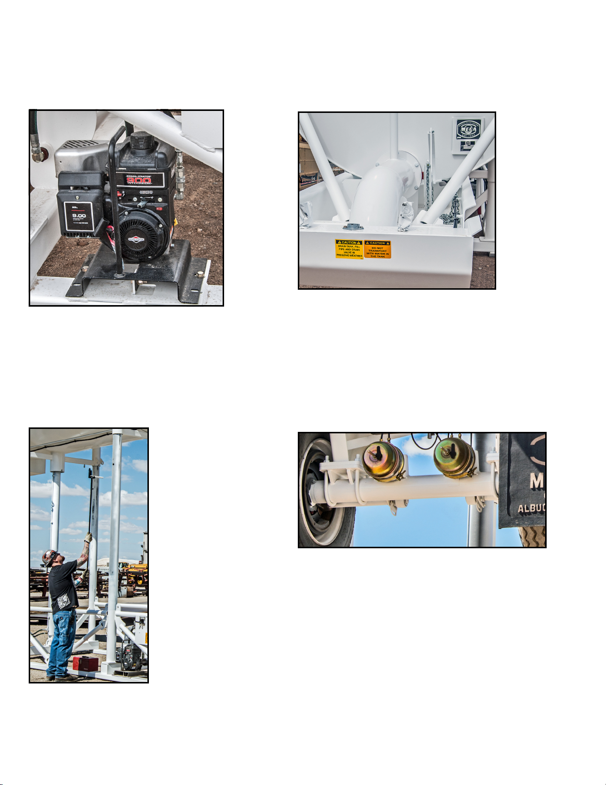
ENGINE
A 6.5 horsepower engine and hydraulic pump that is
mounted on the base of the MPT. The engine is
equipped with a handle for removal and storage after
the tank has been locked in the raised position. Quick
disconnects for the lines to the hydraulic pump are
located on the structure for storage of the hydraulic
hoses after the motor/pump package is removed.
WATER DISCHARGE SYSTEM
The MPT’s water discharge system includes a 10 inch
diameter discharge pipe with a flow rate of
approximately 2,000 gal/min, a shut-off valve with
both a constant force wheel to ensure positive
closure, a weight and pulley system to secure the
chain while positioning the tanker beneath the
discharge pipe spout, and a canvas discharge sock for
the discharge pipe spout.
PIN HANDLER
The Mega Pin Handler is a tool that allows a person to
install and remove all six (6) MPT hitch pins while
standing at ground level, eliminating the need for a
ladder and saving time in the process.
AXLE
The heavy-duty utility axle has a 20,000 lb. capacity
with an oil-lubricated bearing and auto slack
adjusters. It is the highest strength axle tube
generally available for utility vehicle axles. The
materials used allow for a stiffer and stronger axle
beam with no camber required.
The axle utilizes air braking. The backing plate of the
hydraulic brake mounts onto the piloted axle brake
flange, allowing the brakes to perform at their
optimum effectiveness.
2-2
Page 10
SECTION 2
1
2
3
System Description
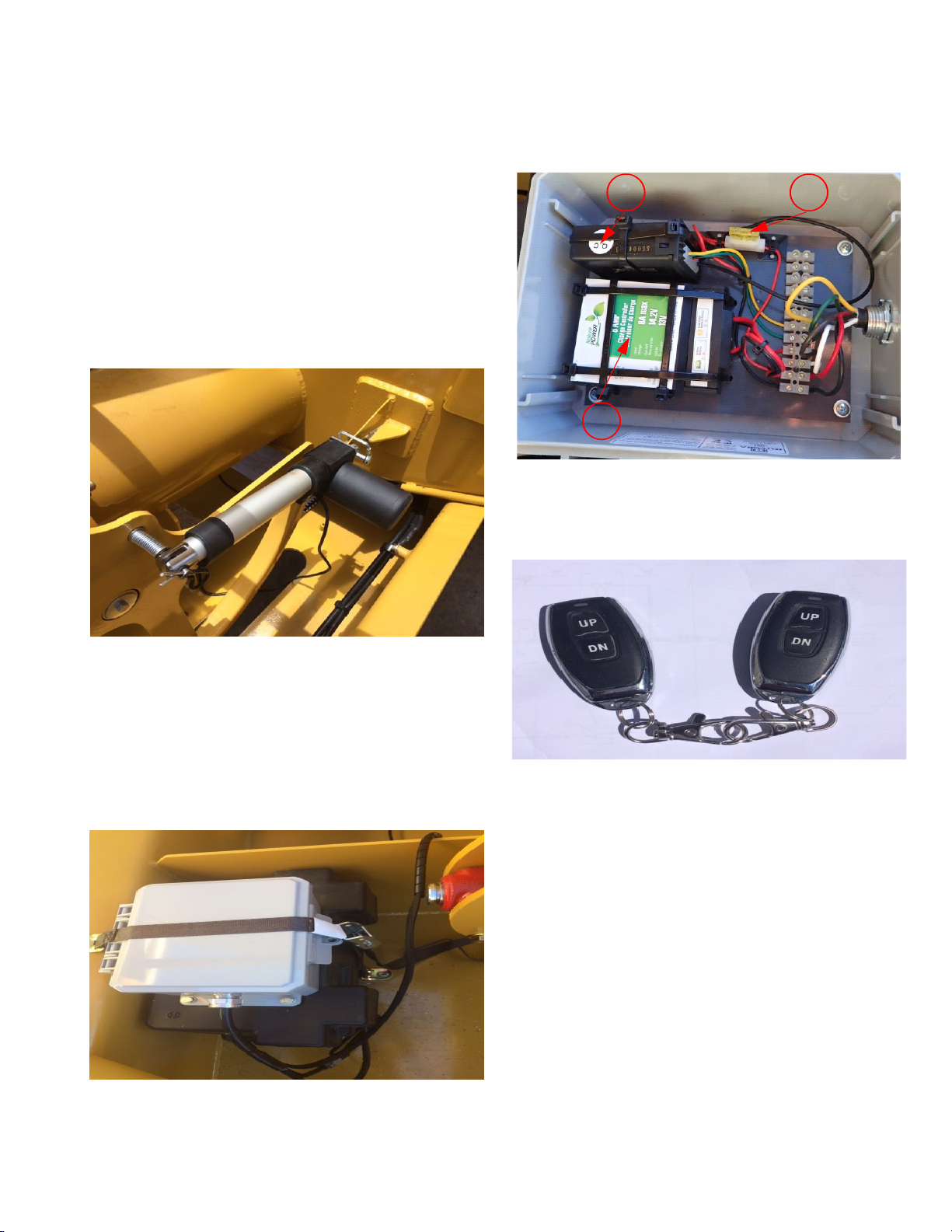
BUTTERFLY VALVE REMOTE CONTROL
SYSTEM (IF EQUIPPED)
The remote control system is designed to let the
operator activate the butterfly valve without using
the force wheel to start and stop water flow from the
tank. The system consists of a linear actuator, remote
control box, remote FOB, sealed battery, and solar
panel charger/analyzer.
Linear Actuator
MPT12 Manual
24 May 2017
1. Remote Control Receiver
2. Solar Panel Charge Controller
3. 20 Amp Actuator Fuse
Mounted to the gooseneck and connected to the
force wheel via a spring-loaded pin. A lanyard is
connected to the spring loaded pin in case power is
low or actuator failure, and the butterfly valve must
be activated by using the manual chain. The actuator
is 12 volts and powered through the remote control
box. Full activator travel is about five (5) seconds.
Remote Control Box
Mounted on top of the battery storage box and
contains the remote control receiver and charger
analyzer. Provides 12-volt power to the linear
actuator as commanded by the remote FOB’s.
Remote FOB’s
Provided to command the operation of the butterfly
valve through the remote control box.
Programming (Remote FOB’s)
The remote control FOB’s can be programmed to
operate in two different ways. From Mega, it is set in
push and hold mode. Push and hold the UP button
to open the valve, push and hold the DN button to
close the valve. If the button is depressed at any time
during open or closing the valve, it will stop in that
position. Mega receives the FOB’s in its default
setting. Press the UP button to open the valve and
the DN button to close the valve. Once pressed and
released, the valve will go to fully open or fully
closed. To stop the valve from opening or closing
fully, press the command directional button a second
time to stop the valve in the commanded position.
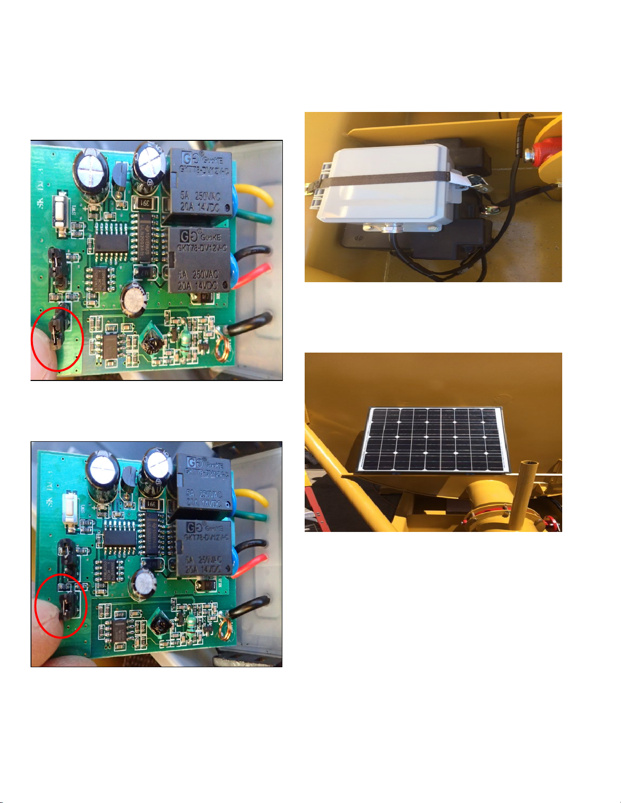
To change the FOB functions , please refer to the
following illustrations: NOTE: Please test prior to
2-3
Page 11
MPT12 Manual
24 May 2017
SECTION 2
System Description
changing functions as the operation of the FOB may
have been changed from the default setting.
• Jumper for S1 on the remote control circuit
board; no pins are connected by the jumper. This
is the DEFAULT setting.
Sealed Battery (Black Box)
A 12-volt sealed battery located in a case and
mounted in the gooseneck. The battery is charged
and conditioned by the chagrer/analyzer unit.
Solar Panel
• Jumper for S1 on remote control circuit board;
both pins connected by jumper. This setting will
activate the “Push and Hold” to operate.
Mounted on the front of the unit. It provides
charging of the sealed battery as controlled by the
charger/analyzer.
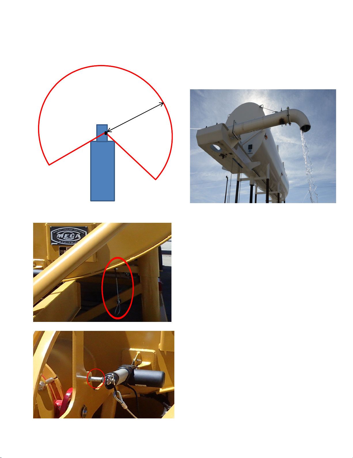
LIMITATIONS
The remote control transmitter range is
approximately 30 to 50 yards (27 to 46 meters) with a
clear line of sight in the raised position. Note: the
transmission range can be limited by metal objects
interfering with the radio signals. See illustration.
2-4
Page 12
MPT12 Manual
M
P
T
1
2
30 – 50 Yards
24 May 2017
SECTION 2
System Description
force wheel to allow for manual operation of the
valve.
SIDE DISCHARGE PIPE (IF EQUIPPED)
Butterfly Valve Remote Control Disconnect
This option provides a means to discharge water to
either side of the unit. The pipe is mounted on a
hinged flange to allow deployment and storage.
Simply unstow the pipe, then swing out to allow
bolting of the hinged flange and secure with the
bolts. Once deployed and bolted, check the wire for
security and adjust the turn buckle accordingly.
Once properly rigged and set, the tank can be raised
and filled.
A disconnect lanyard (1) is provided to allow
disconnect/release of the actuator pin (2) from the
2-5
Page 13

MPT12 Manual
24 May 2017
SECTION 2
System Description
2-6 (Blank)
Page 14

SECTION 3
Commissioning
Contents
Description.........................................................................3-1
DESCRIPTION
The following section details the test procedure steps
required for inspection of the stand tank prior to
placing the stand tank into service. If you are having
difficulties with these procedures, please contact The
MEGA Corp. Product Support Group at: U.S. Toll Free
1-800-345-8889 or Direct 1-505-345-2661 or visit our
website at www.megacorpinc.com for more contact
information.
1. Check hydraulic oil level.
MPT12 Manual
24 May 2017
2. Check oil level in wheel hubs.
3. Check engine oil & fuel.
4. Start engine.
5. Remove locking pins.
6. Raise tank until pin hoist clears top pinhole.
7. Lower tank& replace locking pins.
8. Butterfly in closed position.
9. Fill with water.
10. Pull up on float, adjust valve until water flow
shuts off
11. Fill tank to check operation of float.
12. Drain water back into main supply.
13. Tie down float, toolbox, and hydraulic tank cap.
3-1
Page 15

MPT12 Manual
24 May 2017
SECTION 3
Commissioning
3-2 (Blank)
Page 16
SECTION 4
Operation Instructions
Contents
MPT12 Manual
24 May 2017
Description.........................................................................4-1
Lowering .............................................................................4-1
Transporting ......................................................................4-1
DESCRIPTION
This section includes the steps required for lowering,
transporting, and set-up of the MPT. Failure to adhere
to these steps and their associated warnings,
cautions, and notes may result in death, severe injury,
or damage to the equipment. If your system is not
covered in this manual or you are having difficulties
with the installation please contact The MEGA Corp.
Product Support Group at: U.S. Toll Free 1-800-3458889 or Direct 1-505-345-2661 or visit our website at
www.megacorpinc.com for more contact
information.
LOWERING
1. Read the engine operator’s manual prior to
operation.
2. Remove water from the tank.
Set-Up ..................................................................................4-2
Butterfly Valve Remote Control Disconnect (If
Equipped)...........................................................................4-3
6. Use the hydraulic control valves to lower the tank
until it is resting on the ground.
Keep feet from under the frame or personal injury
could occur. Remove hoses or tools from under
frame before lowering tank.
Extension of the front and rear hydraulic cylinders
are controlled by separate valves. To avoid
damage when raising or lowering the tank adjust
hydraulic cylinders to keep the tank level at all
times.
TRANS PORTIN G
1. Read the engine operator’s manual prior to
operation.
Empty tank of water prior to lowering. Never
move a tank containing water.
3. Start the hydraulic power unit and use the
hydraulic control valves to slightly raise the tank
and remove weight from the hitch pins.
The tank should always be positioned on stable,
level ground before filling with water and/or
raising. The ground beneath the tank must be
capable of supporting the tank and a full payload
of water as well as the weight of the equipment
utilizing the tank.
4. Remove hitch pins and store in the tool box.
5. Turn off the hydraulic power unit.
2. Remove water from the tank.
Empty tank of water prior to transporting. Never
move a tank containing water.
3. Start the hydraulic power unit and use the
hydraulic control valves to lower the tank to level
ground.
4. Start the hydraulic power unit and use the
hydraulic control valves to raise the tank into a
position that aligns the trailer kingpin with the
tractor’s fifth wheel height.
The tank should always be positioned on stable,
level ground before filling with water and/or
raising. The ground beneath the tank must be
capable of supporting the tank and a full payload
of water as well as the weight of the equipment
utilizing the tank.
4-1
Page 17
MPT12 Manual
24 May 2017
SECTION 4
Operation Instructions
5. Back tractor into locking position and connect
the trailer to the tractor. While keeping the tank
level, use the hydraulic control valves to lower the
tank until the tires are on the ground.
Keep feet from under the frame or personal injury
could occur. Remove hoses or tools from under
frame before lowering tank.
Extension of the front and rear hydraulic cylinders
are controlled by separate valves. To avoid
damage when raising or lowering the tank, adjust
hydraulic cylinders to keep the tank level at all
times.
6. Connect air and electrical systems between the
tractor and tank.
7. Check brakes and lights for proper operation.
Check tires for correct air pressure.
8. Use the hydraulic power unit to completely raise
the tank frame.
The tank should always be positioned on stable,
level ground before filling with water and/or
raising. The ground beneath the tank must be
capable of supporting the tank and a full payload
of water as well as the weight of the equipment
utilizing the tank.
SET-UP
1. Read the engine operator’s manual prior to
operation.
2. Select a level area with a stable foundation for
positioning of the tower. The area should be level
in all directions and offer good access to water
haulage equipment.
The tank should always be positioned on stable,
level ground before filling with water and/or
raising. The ground beneath the tank must be
capable of supporting the tank and a full payload
of water as well as the weight of the equipment
utilizing the tank.
3. Disconnect air and electrical controls from the
tractor.
4. Start the hydraulic power unit and remove the
hitch pins from the brackets between the tank
and frame. Retain the pins for use after raising the
tank.
5. Use the hydraulic controls to lower the frame to
the ground. Raise the tank until it is possible to
disconnect the tractor from the tank.
Keep feet from under the frame or personal injury
could occur. Remove hoses or tools from under
frame before lowering tank.
9. Insert hitch pins with hitch pin clips into the
bracket between the tank and tank frame at all
six (6) locations.
10. Pin float ball in locked position.
11. Remove all loose items from the unit. Turn off the
hydraulic power unit. Secure the tool box.
Extension of the front and rear hydraulic cylinders
are controlled by separate valves. To avoid
damage when raising or lowering the tank, adjust
hydraulic cylinders to keep the tank level at all
times.
6. Disconnect the tractor.
7. Remove the float ball pin from the transport
position.
8. Continue to raise the tank evenly until the desired
height is reached.
4-2
Page 18
SECTION 4
Operation Instructions
MPT12 Manual
24 May 2017
9. Install the hitch pins into all six (6) frame legs.
Install all the hitch pins and be sure that they
extend completely through both sides of each
leg. Use the hitch pin installation tool if necessary
to reach the holes.
Failure to install hitch pins in all six (6) frame legs
may result in damage to the tower.
10. Use the hydraulic controls to lower tank until it
rests upon the hitch pins. Turn off the power unit.
Keep feet from under the frame or personal injury
could occur. Remove hoses or tools from under
frame before lowering tank.
Extension of the front and rear hydraulic cylinders
are controlled by separate valves. To avoid
damage when raising or lowering the tank, adjust
hydraulic cylinders to keep the tank level at all
times.
11. Connect the water supply to the tank. Check the
ball float ball and float valve for proper operation.
12. Use tie downs to prevent wind damage to the
tower tank in high wind conditions. Tie-down
locations and details are given in “Figure 4-1: Tiedowns” on page 4-5.
Ensure there is enough distance between the
systems, and all personnel are clear from underneath
tanks. Test to ensure only the desired tank valve
opens when signaled.
REMOTE CONTROL DISCONNECT
To release the pin from the wheel:
1. Remove the pin handler tool from the storage
rack
2. Insert shear pin tool in wire hoop near the left
front leg of tank.
3. Pull down sharply to release cotter pin spring to
eject actuator from wheel. If actuator does not
release from wheel, move manual operation
chain to release tension on actuator until the
actuator springs off of pin allowing manual
operation of butterfly valve
4. Operate the butterfly valve by using the chain.
REMOTE CONTROL RE-CONNECT
To re-install actuator:
1. Ensure tank contains no water
2. Start engine and Raise tank sufficiently to remove
weight from shear pins
3. Remove 6 (six) shear pins and stow in tool box
4. Lower tank to ground
BUTTERFLY VALVE REMOTE CONTROL
DISCONNECT (IF EQUIPPED)
If the valve fails to operate, a release mechanism can
be activated by using the pin installation tool to pull
the release cable. This will release the pin for the
actuator to disengage it from the butterfly valve.
If multiple systems are in close proximity to one
another (less than 100 yards or 92 meters), it may be
possible to operate more then one unit
simultaneously. This may cause unexpected opening
of the butterfly valve releasing water from the tower.
5. Troubleshoot system to isolate failed component
and repair or replace
6. Fully retract actuator
7. Locate wheel pin, three flat washers, spring and
cotter pin
8. Insert actuator pin from the back of the wheel
9. Install one flat washer on outside of pin
10. Install spring on pin
4-3
Page 19
MPT12 Manual
24 May 2017
SECTION 4
Operation Instructions
11. Install one flat washer on outside of spring
12. Compress spring and slide actuator rod onto the
pin
13. Install one flat washer on outside of actuator rod
14. Insert cotter pin in hole of pin.
• Ensure release cable is free and not binding when
cotter pin is installed. Test actuator to ensure correct operation and release cable does not bind or
interfere with butterfly valve wheel, and butterfly
valve moves to the completely closed position.
15. Return stand tank to normal service.
COLD WEATHER STORAGE
Ice will cause serious damage to the fill pipe and fill
pipe valves if water is allowed to freeze in the tank or
water piping. Ensure all water is drained from the unit
when the temperatures are expected to fall below
freezing for any period of time.
1. Ensure that the unit is stable and is positioned on
level ground. Do not lower the tank.
Extension of the front and rear hydraulic
cylinders are controlled by separate valves. To
avoid damage when raising or lowering the tank,
adjust hydraulic cylinders to keep tank level at all
times.
5. Disconnect and drain fill source hosing.
6. Open fill pipe valves. In order to fully drain the
7. fill pipe, the pipe plug (shown in the Section 8
Illustrated Parts Breakdowns) must be
unscrewed.
8. Check to ensure that all water has drained from
tank, fill pipes, and valves.
REACTIVATING UNIT
1. Re-install pipe plug into fill pipe valve.
2. Close discharge BFV and fill pipe valves.
3. Set up the tank in accordance with “Set Up”
operating procedures.
Empty tank of water prior to lowering. Never
move a tank containing water.
2. Shut-off all water fill sources (hydrant or pump) to
the fill pipes.
3. Open discharge BFV and drain water from the
tank. Be careful not to drain the water so quickly
that it will erode the ground beneath the frame.
4. Use the hydraulic controls to lower the frame to
the ground (as described previously in
“Lowering” procedures).
Keep feet from under the frame or personal injury
could occur. Remove hoses or tools from under
frame before lowering tank.
4-4
Page 20
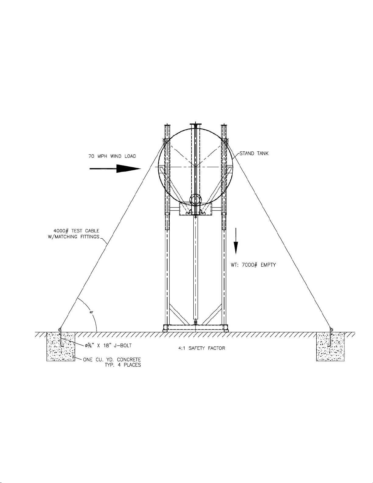
Figure 4-1: Tie-downs
MPT12 Manual
24 May 2017
SECTION 4
Operation Instructions
4-5
Page 21

MPT12 Manual
24 May 2017
SECTION 4
Operation Instructions
4-6 (Blank)
Page 22
SECTION 5
Maintenance and Repair
Contents
MPT12 Manual
24 May 2017
Description.........................................................................5-1
Water Tank..........................................................................5-1
Float Adjustment..............................................................5-2
DESCRIPTION
This section discusses inspection, maintenance, and
repair of the MPT. Failure to perform regular
inspections on your MPT system may result in
damage to the components and reduced life-span of
the MPT. If your system is not covered in this manual
or you are having difficulties with the installation
please contact The MEGA Corp. Product Support
Group at: U.S. Toll Free 1-800-345-8889 or Direct 1505-345-2661 or visit our website at
www.megacorpinc.com for more contact
information.
WATER TANK
Hydraulic Pump Filtration and Installation.............5-3
Axle .......................................................................................5-3
4. (Interior coating equipped only) Inspect tank
interior coating for wear, condition and
deterioration. Repair as required.
5. Inspect all water ways, pipes, and couplings for
security, wear and leaks.
6. Inspect all tank mounted wiring, and hydraulic
hoses for wear, security and leaks.
REPAIR
Paint
Remove corrosion. Prime and paint.
Interior Coating (Epoxy or Urethane)
1. Brief and follow all local confined space entry
requirements and procedures.
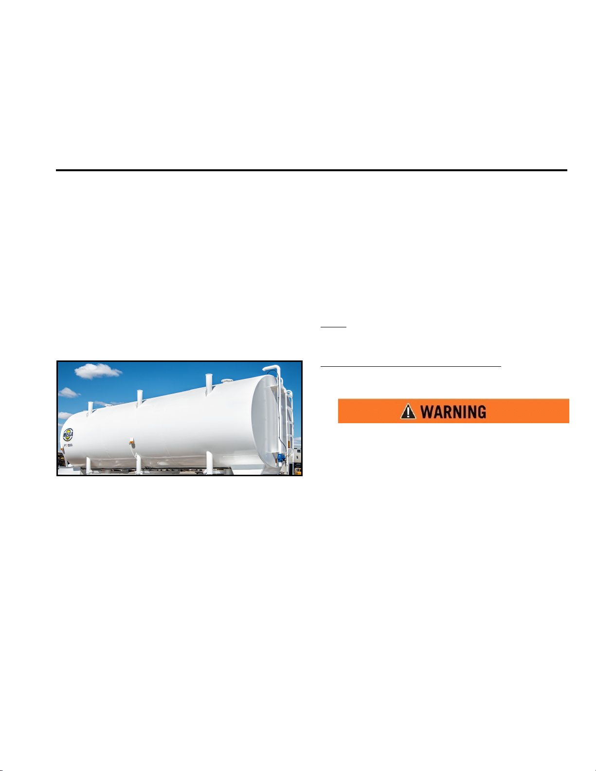
The MPT tank is 2.59m (8.5 ft) in diameter, 11.13m
(36.5 ft.) in length, and has a capacity of 45.42 L
(12,000 gallons). The corners of the tank are
reinforced to provide sturdy connection to supports.
An access ladder leading to the top of the tank is
located at the rear of the trailer, and a ladder is
located inside of the tank. An 8” diameter float is
located inside of the tank for automatic fill shut-off
when the tank is full.
INSPECTION
1. Inspect tank exterior paint for wear and
corrosion.
2. Inspect tank outer skins for damage or leaks.
3. Inspect tank outer structure for damage.
Do not enter confined spaces without following
established site specific procedures. Failure to
follow proper safety procedures will result in
serious injury or death.
2. Use all required safety equipment and
procedures to perform grinding and painting of
interior coatings. Refer to coating manufactures
MSDS information.
3. Inspect coating for flaking, bubbling or cracking.
4. Remove damaged coating via wire brush wheel
or grinder. Ensure coating is removed about 1-2”
beyond the visible crack.
5. Wipe area clean and inspect exposed edges of
the coating. Ensure exposed edges of the coating
still adhere to the metal surface.
6. Wipe clean with Prep Sol or equivalent
preparation solution to remove debris and/or oil.
5-1
Page 23
MPT12 Manual
24 May 2017
SECTION 5
Maintenance and Repair
7. Mix Epoxy or Urethane coating according the
manufacturer’s instructions.
8. Apply coating with roller or natural haired brush.
Ensure coating in applied at the manufacturer’s
recommended thickness. See MSDS sheet for
details.
9. Allow sufficient time for the coating to cure
before filling tank with water.
Leaks
1. Remove paint and corrosion from suspected area.
2. Weld over leak.
3. Prime and paint over weld.
Structure
Contact MEGA Product Support for assistance on
major structural repair at US toll free: 1-800-345-8889
Direct: 1-505-345-2661 or visit our website at
www.megacorpinc.com
information.
for more detailed contact
4. Water should be coming out of float valve (if not
open flow control valve ¼ turn).
5. Pull up on float.
6. If water will not shut off, close flow control
valve ¼ of a turn.
7. Pull up on float (adjust control valve until water
shuts off).
DOUBLE FILL PIPE
FLOAT ADJUSTMENT
SINGLE FILL PIPE
1. Open flow control valve all the way. then close.
1. Make sure both shut off valves are open before
adjusting.
2. Open flow control valves on both fill pipes all the
way. then close.
3. Open flow control valves on both fill
pipes 3 to 3-1/2 turns.
4. Start fill.
5. Water should be coming out of float valve (if not
open flow control valve ¼ turn).
2. Open flow control valve 3 to 3-1/2 turns.
3. Start fill.
6. Pull up on float.
5-2
Page 24
SECTION 5
Maintenance and Repair
MPT12 Manual
24 May 2017
7. If water will not shut off, close flow control valve a
¼ of a turn.
8. Pull up on float (adjust flow control valve until
water shuts off on both fill pipes).
9. Close both shut off valves on each fill pipe to
make sure both valves are shutting off.
10. Open shut off valves.
HYDRAULIC PUMP FILTRATION AND
INSTALLATION
Please follow coupling manufacturer’s recommended
installation instructions
For maximum pump and system component life, the
system should be protected from contamination at a
level not to exceed 214 particles greater than 10
microns per milliliter of fluid.
LUBRICATION
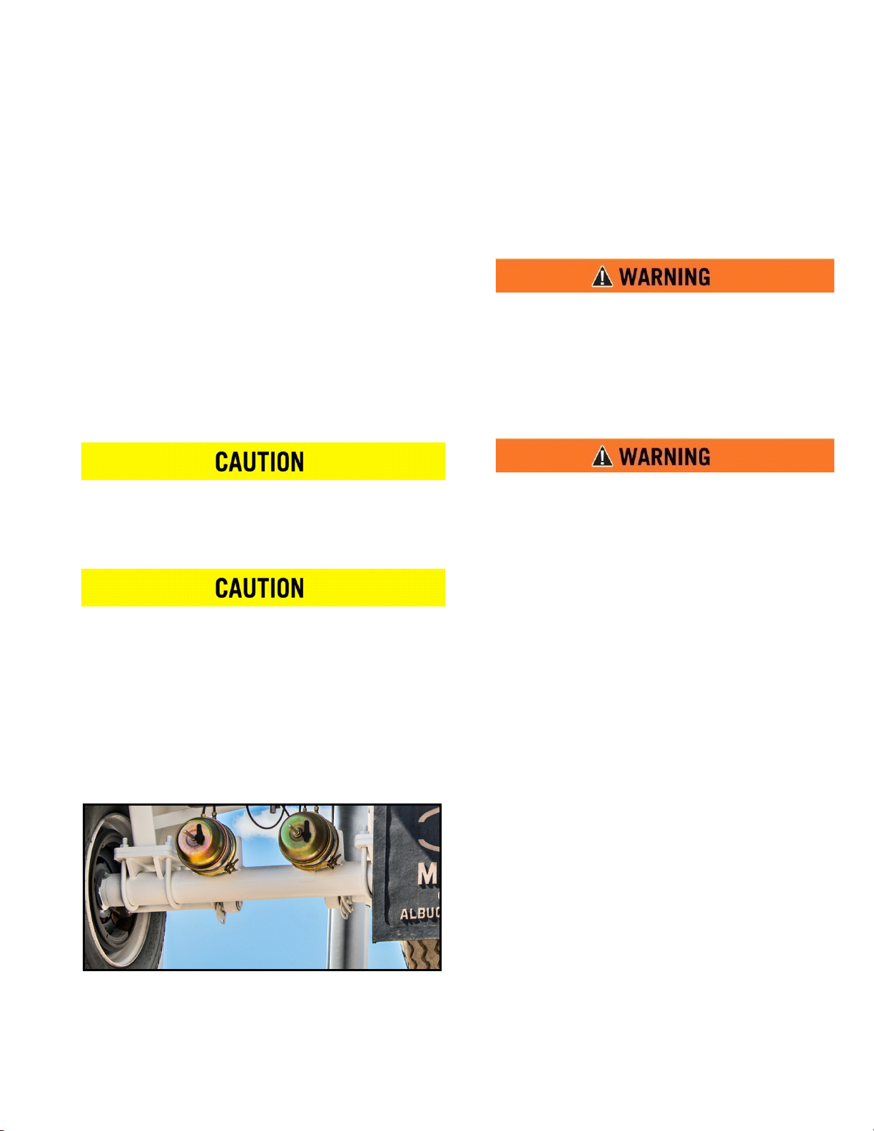
1. Check oil level. If below 0.25”, add oil.
2. Inspect for grease or oil contamination. Change if
required, using the approved greases listed in
Table 5-1.
Do NOT use gasoline to clean parts. Gasoline can
explode or burn, resulting in serious personal
injury or death.
3. Check for grease or oil on the brake disc, drum, or
linings. If necessary, clean the disc or the drum
and replace contaminated linings.
The presence of grease or oil on the brake disc,
drum, or linings can cause poor brake
performance, leading to serious injury or death
and equipment damage.
Pump and motor shaft alignment must be within
0.007 inches total indicator reading using a standard
float coupling. Please follow coupling manufacturer’s
recommended installation instructions to prevent
end thrust on pump shaft. Turn pump by hand to
assure freedom of rotation. Pump and motor must be
on a rigid base. The coupling should be sized to
absorb the peak horsepower developed.
AXLE
The heavy-duty utility axle has a 25,000 lb. capacity
with an oil-lubricated bearing, auto slack adjusters.
and electro-hydraulic air braking. The backing plate
of the hydraulic brake mounts onto the piloted axle
brake flange.
BUTTERFLY VALVE REMOTE CONTROL
SYSTEM (IF EQUIPPED)
If actuator runs slow:
1. Ensure battery connections are good and clean
2. Check battery voltage, ensure battery voltage is
12 VDC to 14.2 VDC
3. Check to ensure solar charging system functions
properly
4. Green LED illuminated – Battery Charged (14.2
VDC)
5. Yellow LED illuminated – Charging (<13 VDC cut
in charge voltage)
6. Check and ensure actuator wiring and
connectors are is good condition and there is no
corrosion or damage present
7. Check butterfly valve to ensure valve is not
binding or dragging
8. Repair as required
If actuator fails to operate:
1. Check battery voltage, ensure battery voltage is
12VDC to 14,2 VDC
2. Ensure all power and ground connections are in
good shape with no corrosion or damage present
5-3
Page 25
MPT12 Manual
24 May 2017
SECTION 5
Maintenance and Repair
3. Check fuse for remote control actuator, ensure
fuse is good
a. If 20 amp fuse in control enclosure box is
blown, high current draw is present
1. Possible damaged actuator, short to
ground in wiring or motor, cut or
damaged wiring or stuck butterfly valve
2. Check to ensure butterfly valve operates
correctly and does not bind or stick
3. Check actuator to ensure maximum
current draw at load does not exceed 12
Amps
4. Check/replace batteries in remote control fobs
a. Replacement batteries are: 2 each CR2016 3V
Lithium cell batteries
5. Check remote control circuit output
a. Ensure when remote control is activated the
output signal is directed to actuator
6. Repair as required
Remote Control System Specifications
• Wireless remote control - Fuse protection – 20
Amp fuse inside of enclosure, 30 to 50 yard operating range, IP65 protection rating, 2 modes of
operation; UP/DOWN (OPEN/CLOSE) (1) Push to
start/Push to stop or (2) Push and hold to operate,
release to stop
• Battery – Group 27 AGM (Absorbed Glass Mat,
spill proof, no maintenance required) 12VDC, 100
Amp Hour rating
• Solar panel – 65 Watt, 3.71 Amps, 12 VDC
monocrystalline panel.
• Solar panel charge controller - 13 VDC cut in voltage, 14.2 VDC cutout voltage, 8 Amp maximum
• Electric actuator – 12 VDC operation, 6” stroke,
400 pound capacity, travel speed 0.98”/second,
IP66 protection rating, 12 Amp maximum full
load current draw, 20% duty cycle, built in travel
limit switches
GREASE AND OIL SPECIFICATIONS
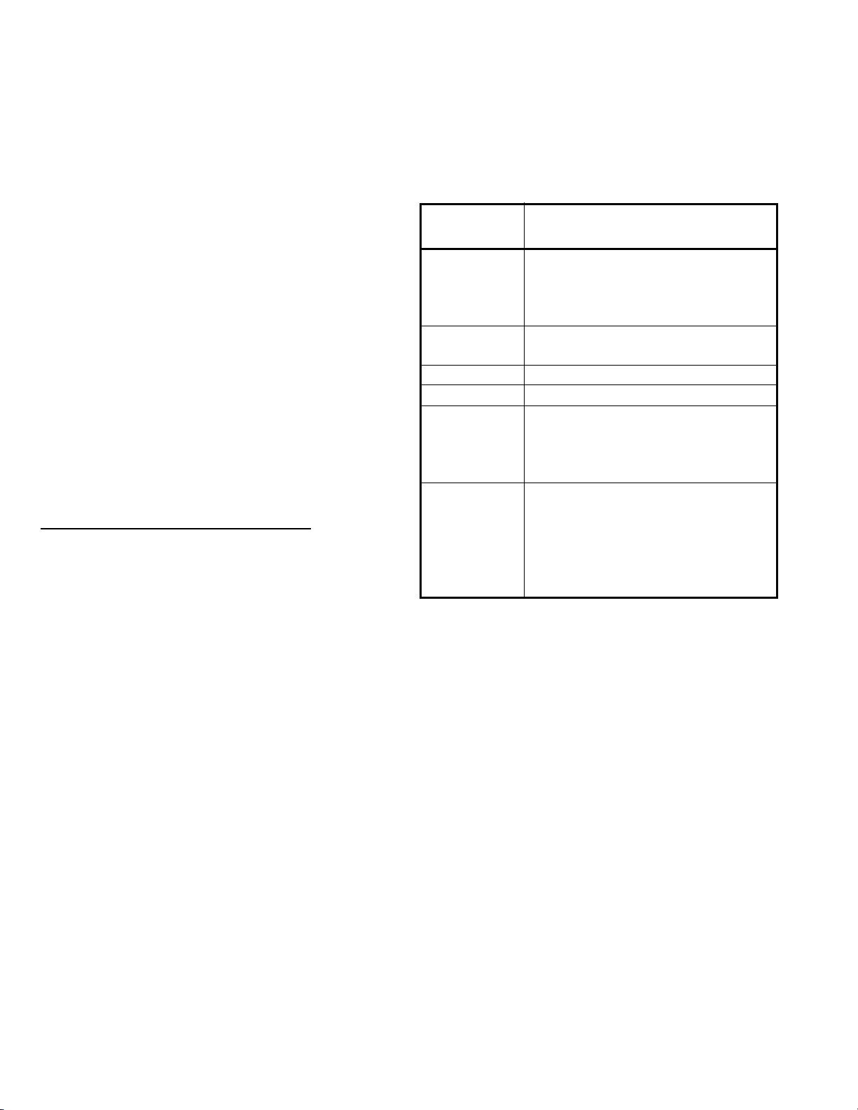
Table 5-1: Approved Greases
Lubricant
Specification
O-616-A
O-617-A
0-617-B
0-637 Witco Chemical Corp. SA-824946
O-641 Never-Seez Anti-Seize
O-645
O-692
Recommendation
Shell Darina Grease No. 1
Texaco Th ermatex EP-1
Texaco Hytherm EP-1
Aralub 3837
Multipurpose Chassis Grease
Mobilgrease 2B (Military)
Mobiltemp SHC 32 (Industrial)
Aerospace Lubricants Inc.
Triolube 12 - Grade 1
Amoco Super Permalube # 2
Citgo Premium Lithium EP-2 #2
Exxon Ronex MP-2 #2
Kendall L-427 Super Blu #2
Mobilith AW-1 #1
Sohio Factran EP-2 #2
5-4
Page 26
MPT12 Manual
SECTION 5
Maintenance and Repair
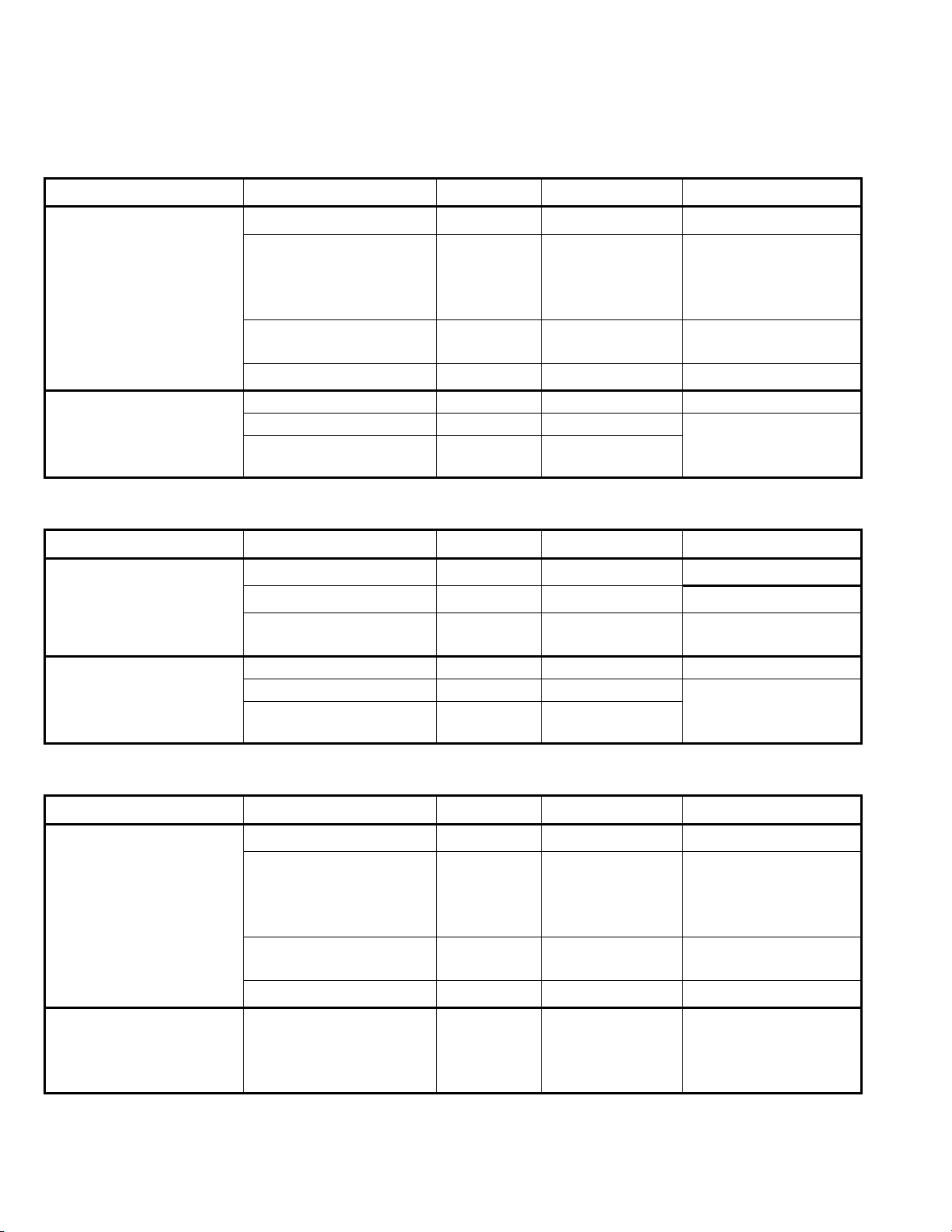
Table 5-2: Cam Brake Grease Specifications
Component Rockwell Specification NLGI Grade Grease Type Outside Temperature
Hold Down Clips,
Anchor Pins,
Rollers (Journals only)
Camshaft Bushings
Camshaft Splines
O-616-A 1 Clay Base
O-617-A
or
O-617-B
O-645 2
1
2
Lithium
12-Hydroxy
Steadate or
Lithium Complex
Synthetic Oil,
Clay Base
O-692 1 and 2 Lithium Base
Any of Above See Above See Above See Above
O-637 1-1/2 Calcium Base See grease
O-641 — Anti-Seize
Down to -40
See grease
manufacturer’s
specifications
Down to -54
Down to -40
manufacturer’s
specifications
24 May 2017
o
C (-40oF)
o
C (-65oF)
o
C (-40oF)
Table 5-3: Automatic Slack Adjuster Grease Specifications
Component Rockwell Specification NLGI Grade Grease Type Outside Temperature
Automatic Slack Adjuster
O-616-A 1 Clay Base
O-692 1 and 2 Lithium Base
O-645 2
Synthetic Oil,
Clay Base
Down to -40
Down to -40
Down to -54
Any of Above See Above See Above See Above
Clevis Pins
O-637 1-1/2 Calcium Base See grease
O-641 — Anti-Seize
manufacturer’s
specifications
Table 5-4: Manual Slack Adjuster Grease Specifications
Component Rockwell Specification NLGI Grade Grease Type Outside Temperature
Manual Slack Adjuster
Clevis Pins
O-616-A 1 Clay Base
O-617-A
or
O-617-B
O-645 2
1
2
Lithium
12-Hydroxy
Steadate or
Lithium Complex
Synthetic Oil,
Clay Base
O-692 1 and 2 Lithium Base
Any of Above
O-637
O-641
See Above
1-1/2
—
See Above
Calcium Base
Anti-Seize
Down to -40
See grease
manufacturer’s
specifications
Down to -54
Down to -40
See Above
See grease
manufacturer’s
specifications
o
C (-40oF)
o
C (-40oF)
o
C (-65oF)
o
C (-40oF)
o
C (-65oF)
o
C (-40oF)
5-5
Page 27
MPT12 Manual
24 May 2017
Component Rockwell Specification
Trailer Axle
Wheel End
SECTION 5
Maintenance and Repair
Table 5-5: Trailer Axle Wheel Oil Specifications
Outside Temperature
Military
Specifications
O-76A, Gear Oil MIL-L-2105-D GL-5, SAE 85W/140 10 None -12 None
O-76D, Gear Oil MIL-L-2105-D GL-5, SAE 8OW/90 -15 None -26 None
O-76E, Gear Oil MIL-L-2105-D GL-5, SAE 75W/90 -40 None -40 None
O-76J, Gear Oil MIL-L-2105-D GL-5, SAE 75 -40 +35 -40 +2
O-76L, Gear Oil MIL-L-2105-D GL-5, SAE 75W/140 -40 None -40 None
O-76M, Full Synthetic Oil MIL-L-2105-D GL-5, SAE 75W/140 -40 None -40 None
O-76N, Full Synthetic Oil MIL-L-2105-D GL-5, SAE 75W/90 -40 None -40 None
Table 5-6: Trailer Axle Wheel Grease Specifications
Grease Type
o
F
Min. Max. Min. Max.
o
C
Grease Rockwell Specification NLGI Grade
Multi-Purpose
Grease
Trailer Axle Bearing O-647 00 Lithium Complex
O-617-A
or
O-617-B
1
2
Grease
Classification
Lithium 12-
Hydroxy Stearate
or Lithium
Complex
Outside Temperature
Refer to the grease
manufacturer’s
specifications for the
temperature service limits.
Refer to the grease
manufacturer’s
specifications for the
temperature service limits.
5-6
Page 28
SECTION 6
Scheduled Maintenance Inspections
Contents
MPT12 Manual
24 May 2017
Description.........................................................................6-1
Axle and Brake System...................................................6-1
MPT Structure ...................................................................6-1
Control System .................................................................6-2
DESCRIPTION
This section establishes scheduled maintenance inspections of the MPT at the designated frequencies.
Performing these inspections will identify potential system discrepancies and allow preventative maintenance
to be performed before a component or system is rendered totally inoperative.
**NOTE: The recommended oil change intervals are based upon operating conditions, speeds, and loads.
Limited service applications may allow the recommended interval to be increased. Sever service applications
may require the recommended interval to be reduced. For more information, contact Mega Product Support at
U.S. Toll Free 1-800-345-8889 or Direct 1-505-345-2661 or visit our website at www.megacorpinc.com for more
contact information.
FREQUENCY
AXLE AND BRAKE SYSTEM
Checkoillevel.Changeoiliftheoillevelislessthan0.25”.
Additionally, change the oil and grease the bearings
wheneverthewheelendisdisturbedduringwheelorhub
removaloriftheoiliscontaminated.
(Heavy‐DutyService)IftheMPTaccumulatesover60,000
milesayear,changetheoilandgreasethebearingsevery
30,000miles.
(Heavy‐DutyService)IftheMPTaccumulateslessthan
60,000milesayear,changetheoilandgreasethe
bearingseverysixmonths.
(Standard‐DutyService)IftheMPTaccumulatesover
100,000milesayear,changetheoi l andgreasethe
bearingsevery100,000miles.
(Standard‐DutyService)IftheMPTaccumulateslessthan
100,000milesayear,changetheoi l andgreasethe
bearingsonceayear.
1000MILES 30,000MILES 100,000MILES EVERY6MONTHS ANNUALLY
X
X
X
X
X
Checkbrakepodsforsecurity,damage,andleaks
STEP
Checkfillerporttrashscreenfordebrisand
1
inspectassemblyforsecurityanddamage.Repair
orreplacetrashscreenasrequired.
Visuallyinspectiontankexteriorfordamageand
2
evidenceofleaks.Repairasrequired
Checkalllightsforproperoperation.Replace
3
lightsasrequired.
Checkallinteriortankstructureforleaks,cracks
4
andconditionofepoxycoating(ifequipped).
Repairstructureandcoatingsasrequired.
MPT STRUCTURE
150HRS
(WEEKLY)
X
6-1
250HRS
(BI‐WEEKLY)
FREQUENCY
500HRS
(MONTHLY)
X
X
X
1,000HRS
(QUARTERLY)
5,000HRS
(ANNUALLY)
X
Page 29
MPT12 Manual
24 May 2017
STEP
Checkenginehydraulictankhosesandcylinders
1
fordamage,leaks,andsecurity.Repairas
required.
Inspectdischargeandinletvalvesfordamage,
2
leaks,andsecurity.Repairasrequired.
Scheduled Maintenance Inspections
CONTROL SYSTEM
SECTION 6
150HRS
(WEEKLY)
250HRS
(BI‐WEEKLY)
FREQUENCY
500HRS
(MONTHLY)
X
X
1,000HRS
(QUARTERLY)
5,000HRS
(ANNUALLY)
6-2
Page 30
SECTION 7
Recommended Support Parts
Contents
MPT12 Manual
24 May 2017
Description.........................................................................7-1
Hydraulic Pump & Engine Parts Group.....................7-1
Water Flow Parts Group .................................................7-1
Brakes Group.....................................................................7-1
Lights Parts Group...........................................................7-1
Miscellaneous Parts Group...........................................7-2
DESCRIPTION
This section contains a listing of recommended support parts to have on the shelf. Do not forget that all MPTs
are not configured the same, and that there are several variations of parts. Ensure MPT serial numbers and
actual component part numbers are checked before ordering any parts.
A. HYDRAULIC PUMP & ENGINE PARTS GROUP
PART DESCRIPTION PART NO. QTY
1. Pump, Hydraulic Gear (4ZC31) 302100 1
2. Flow Control Valve 302244 1
3. Oil Filter, Return 302316 1
B. WATER FLOW PARTS GROUP
PART DESCRIPTION PART NO. QTY
1. Valve, Butterfly, 10” 301486 1
2. Discharge Sock w/Metal Grommet 302253 1
3. Discharge Sock (“Drawstring Style”) 304856 1
4. Worm Drive Clamp 304855 1
5. Float Assembly See Illustrated Parts Breakdown
6. Hairpin 354671
7. Valve, Float, 1” 303202 1
8. Valve, In-Line 3” 302457 1
C. BRAKES GROUP
PART DESCRIPTION PART NO. QTY
1. Couplers, Gladhand, Blue, Emergency Brake Driver’s Side 301300
2. Couplers, Gladhand, Red, Service Brake Passenger Side 301301
3. Petcock, 1/4” 300296 1
D. LIGHTS PARTS GROUP
PART DESCRIPTION PART NO. QTY
1. Clearance Light, Red 355374 2
2. Clearance Light, Amber 355375 4
3. Stop/Tail Light 302607 4
4. Light Bar 300241 1
5. Screw, Pan 10–24 UNC X 0.75 354647 4
6. Nut, Lock 10–24 354648 4
7. Washer, Flat #10 350000 4
7-1
Page 31

MPT12 Manual
24 May 2017
SECTION 7
Recommended Support Parts
E. MISCELLANEOUS PARTS GROUP
PART DESCRIPTION LOCATION / USE PART NO. QTY
1. Chain Front of trailer 353540 1
2. Weight, Counter Balance End of rope on MPT 10 or MPT 12 034810 1
3. Rope Assembly Front of trailer 032826 1
4. Pulley, Swivel
5. Hitch Pin Assembly & Keepers At side posts of tower tank 354255
6. Lynch Pin with Chain At side posts of tower tank 354257
If your system is not covered in this manual or are having difficulties locating the necessary components please
contact MEGA Corp. Product Support Group at:
US Toll Free: 1-800-345-8889 or
Direct: 1-505-345-2661 or visit our website at www.megacorpinc.com for more detailed contact information.
Passenger side of trailer; rope attaches to pully to
smooth the travel of rope
354276 1
7-2
Page 32
SECTION 8
Illustrated Parts Breakdown
Contents
MPT12 Manual
24 May 2017
Description.........................................................................8-1
Single Fill Pipe Float Assembly ....................................8-1
Dual Fill Pipe Float Assembly .......................................8-2
Discharge Valve Group .................................................. 8-3
Hydraulic Control Valve Assembly.............................8-4
Lights....................................................................................8-5
DESCRIPTION
This section contains illustrated parts breakdowns of several MPT assemblies. Do not forget that all MPTs are
not configured the same, and that there are several variations of parts. Ensure MPT serial numbers and actual
component part numbers are checked before ordering any parts.
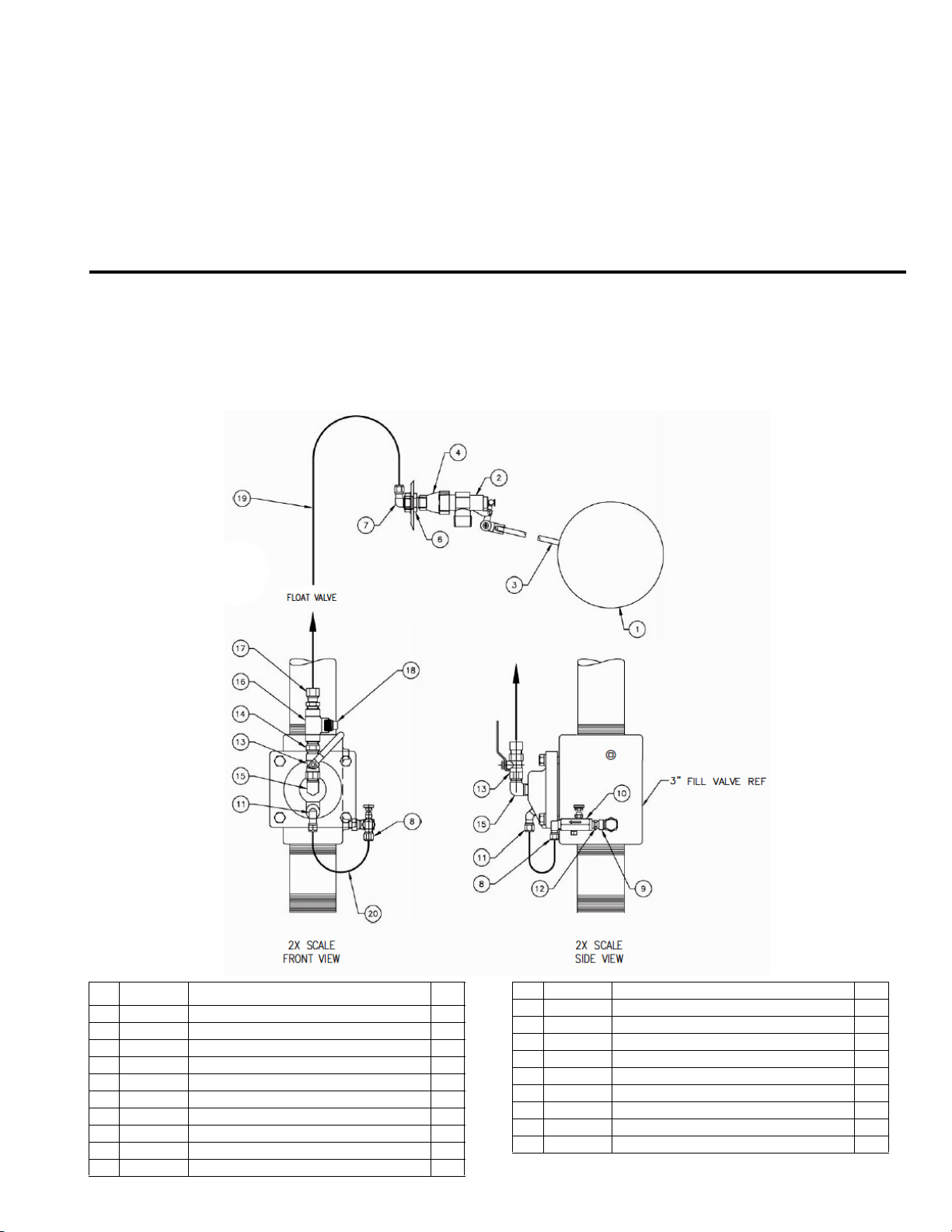
SINGLE FILL PIPE FLOAT ASSEMBLY
NO. PART NO. DESCRIPTION QTY
1 354259 BALL FLOAT 1
2 303202 FLOAT VALVE–1” BRASS 1
3 354422 3/8” ALL-THREAD X 7.00” 1
4 352706 BELL REDUCER 1/2 FPT TO 1 FPT 1
5 354337 HAIRPIN COTTER—3/16” 1
6 354258 CLAMPING STUD 1
7 351088 AIR FTG 1469x8 1
8 351082 AIR FTG 1469x6 1
9 352892 AERO FTG 2089–6–4S 1
10 300283 CONTROL VALVE—1/4 NPT 1
11 351124 AIR FTG 1480x6 1
12 352467 AERO FTG 2083–4–4S 1
13 301299 BALL VALVE, 1/2” EPT 1
14 352472 AERO FTG 2083–8–8S 1
15 354037 AERO FTG 2085–8–8S 1
16 352858 AERO FTG 2090–8–8S 1
17 351072 AIR FTG 1469x8x8 1
18 350852 PLUG, PIPE 1/2” SQ. HEAD 1
19 351142 TUBING—ø1/2” x 126” 1
20 351141 TUBING—ø3/8 x 12” 2
8-1
Page 33
MPT12 Manual
24 May 2017
Illustrated Parts Breakdown
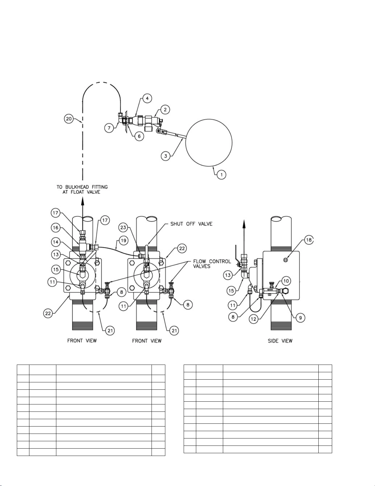
DUAL FILL PIPE FLOAT ASSEMBLY
SECTION 8
NO. PART NO. DESCRIPTION QTY
1 354259 BALL FLOAT 1
2 303202 FLOAT VALVE–1” BRASS 1
3 354422 3/8” ALL-THREAD X 7.00” 1
4 352706 BELL REDUCER 1/2 FPT TO 1 FPT 1
5 354337 HAIRPIN COTTER—3/16” 1
6 354258 CLAMPING STUD 1
7 351088 AIR FTG 1469x8 1
8 351082 AIR FTG 1469x6 2
9 352892 AERO FTG 2089–6–4S 2
10 300283 CONTROL VALVE—1/4 NPT 2
11 351124 AIR FTG 1480x6 2
12 352467 AERO FTG 2083–4–4S 2
13 301299 BALL VALVE, 1/2” FPT 2
14 352472 AERO 2083–8–8S 1
15 354037 AERO 2085–8–8S 2
16 352858 AERO 2090–8–8S 1
17 351072 AIR FTG 1468x8x8 2
18 350851 PIPE PLUG — 3/8” 2
19 351142 TUBING—ø1/2” x 24” 1
20 351142 TUBING—ø1/2” x 126” 1
21 351141 TUBING—ø3/8 x 12” 4
22 302457 VALVE, 3” 2
23 351091 AIR FTG 1469x8x8 1
8-2
Page 34
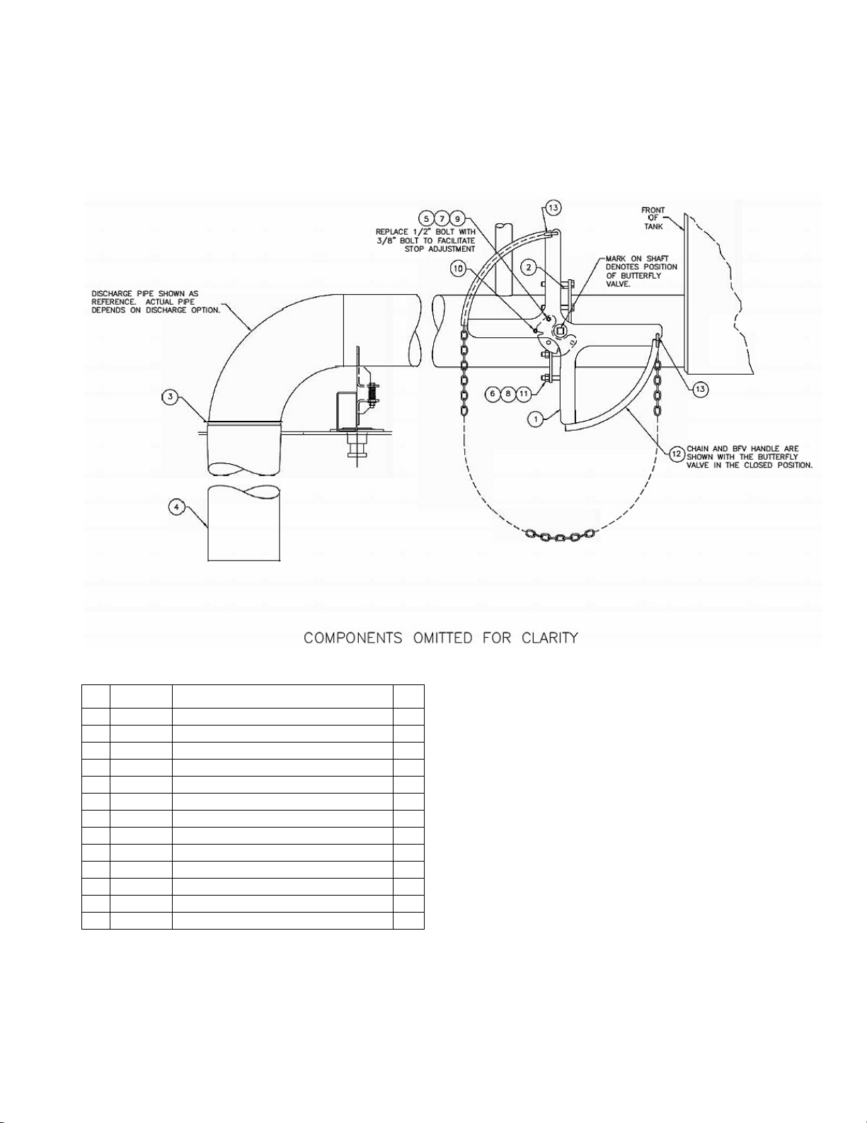
DISCHARGE VALVE GROUP
MPT12 Manual
24 May 2017
SECTION 8
Illustrated Parts Breakdown
NO. PART NO. DESCRIPTION QTY
1 018408 BFV HANDLE ASSEMBLY 1
2 301486 BUTTERFLY VALVE, 10” 1
3 304855 WORM-DRIVE CLAMP 1
4 304856 DISCHARGE SOCK, ø11.5” 1
5 350003 WASHER, FLAT 3/8 1
6 350006 WASHER, FLAT 5/8 12
7 350025 NUT, HEX 3/8—16 UNC 1
8 350029 NUT, HEX 5/8—11 UNC 6
9 350146 SCREW, CAP 3/8—16 UNC X1.25 1
10 350148 SCREW, CAP 3/8—16 UNC X1.75 1
11 350295 SCREW, CAP 5/8—11 UNC X5.00 6
12 353540 UTILITY CHAIN, 3/16” X 23’–0” 1
13 354272 COLD SHUT, 1/4” 2
8-3
Page 35
MPT12 Manual
24 May 2017
SECTION 8
Illustrated Parts Breakdown
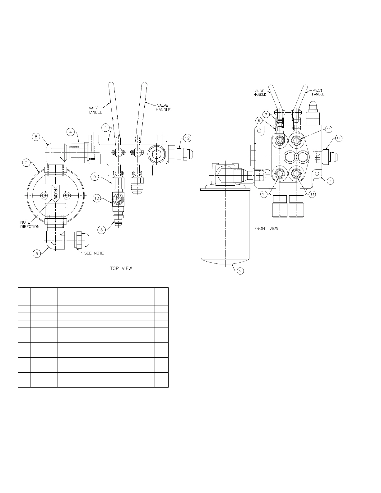
HYDRAULIC CONTROL VALVE ASSEMBLY
NO. PART NO. DESCRIPTION QTY
1 302244 VALVE, HYDRAULIC CONTROL 1
2 302316 FILTER 1
3 352310 AERO 2021–8–8S 1
4 353225 AERO 2216–8–10S 1
5 352452 AERO 2024–12–12S 1
6 352871 AERO 2081–8–4S 1
7 354588 AERO FD90 –1045–4–4S 1
8 354070 AERO 2085–12–8S 1
9 354340 AERO 2216–8–8S 1
10 354704 TEE AERO 2092–8–8S 1
11 352612 AERO 202702–8–10S 3
12 352616 AERO 202702–10–8S 1
8-4
Page 36
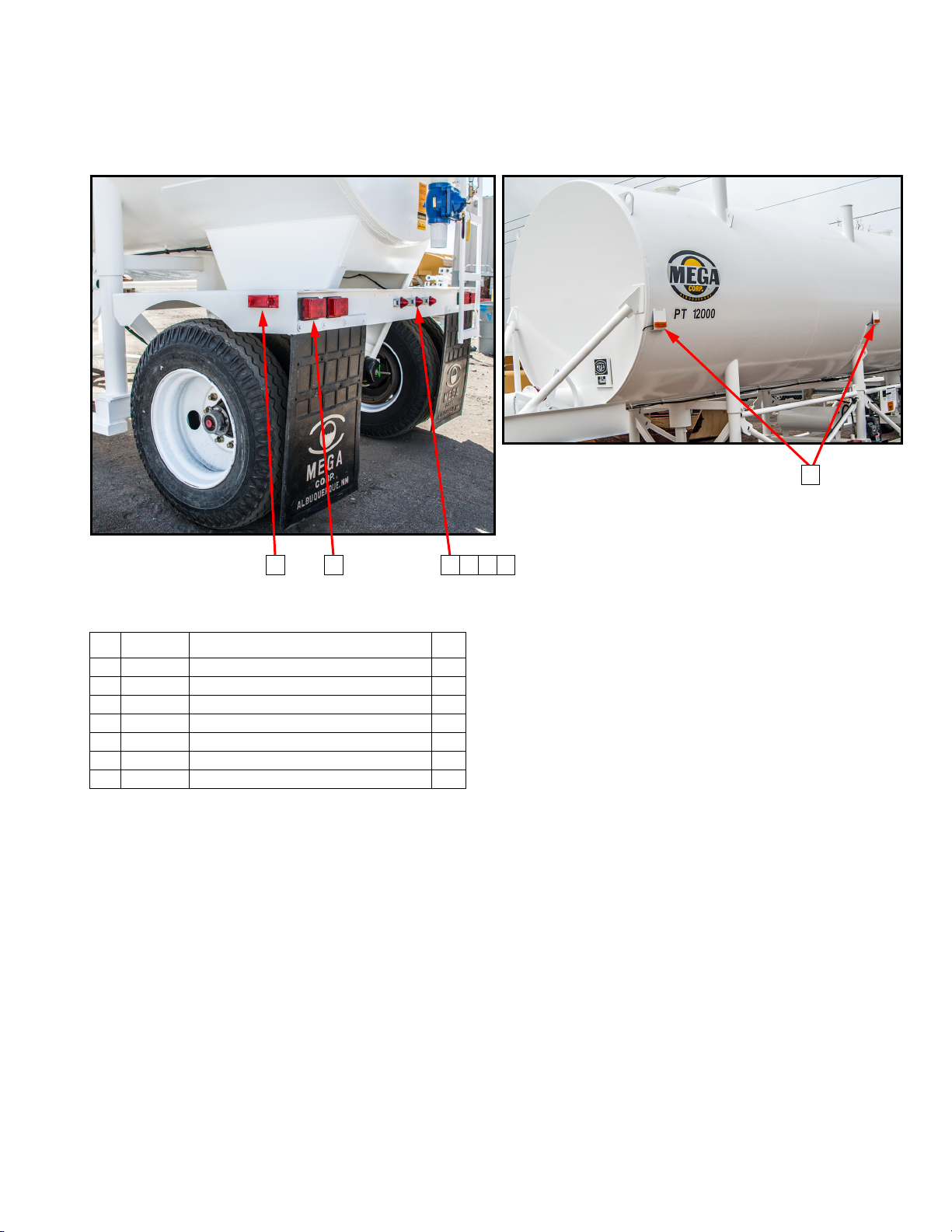
LIGHTS
31 4 5 6 7
2
MPT12 Manual
24 May 2017
SECTION 8
Illustrated Parts Breakdown
NO. PART NO. DESCRIPTION QTY
1 355374 CLEARANCE LIGHT, RED 2
2 355375 CLEARANCE LIGHT, AMBER 4
3 302607 STOP/TAIL LIGHT 4
4 300241 LIGHT BAR 1
5 354647 SCREW, PAN 10–24 UNC X 0.75 4
6 354648 NUT, LOCK 10–24 4
7 350000 WASHER, FLAT #10 4
8-5
Page 37

MPT12 Manual
24 May 2017
SECTION 8
Illustrated Parts Breakdown
8-6 (Blank)
Page 38

SECTION 9
Appendix: Installation Drawings
DESCRIPTION
This section contains all the drawings required to
assemble, transport, and operate the MPT12. These
drawings are MPT12 serial number specific and are
designed to be used in conjunction with previous
section information to successfully produce a fully
operational MPT12 system.
If your system is not covered in this manual, you are
having difficulties with the installation or need
additional information or assistance, please contact
The MEGA Corp. Product Support Group at:
U.S. Toll Free: 1-800-345-8889
Direct: 1-505-345-2661
or visit our website at www.megacorpinc.com for
more contact information.
MPT12 Manual
24 May 2017
9-A
Page 39

MPT12 Manual
24 May 2017
SECTION 9
Appendix: Installation Drawings
9-B (Blank)
Page 40
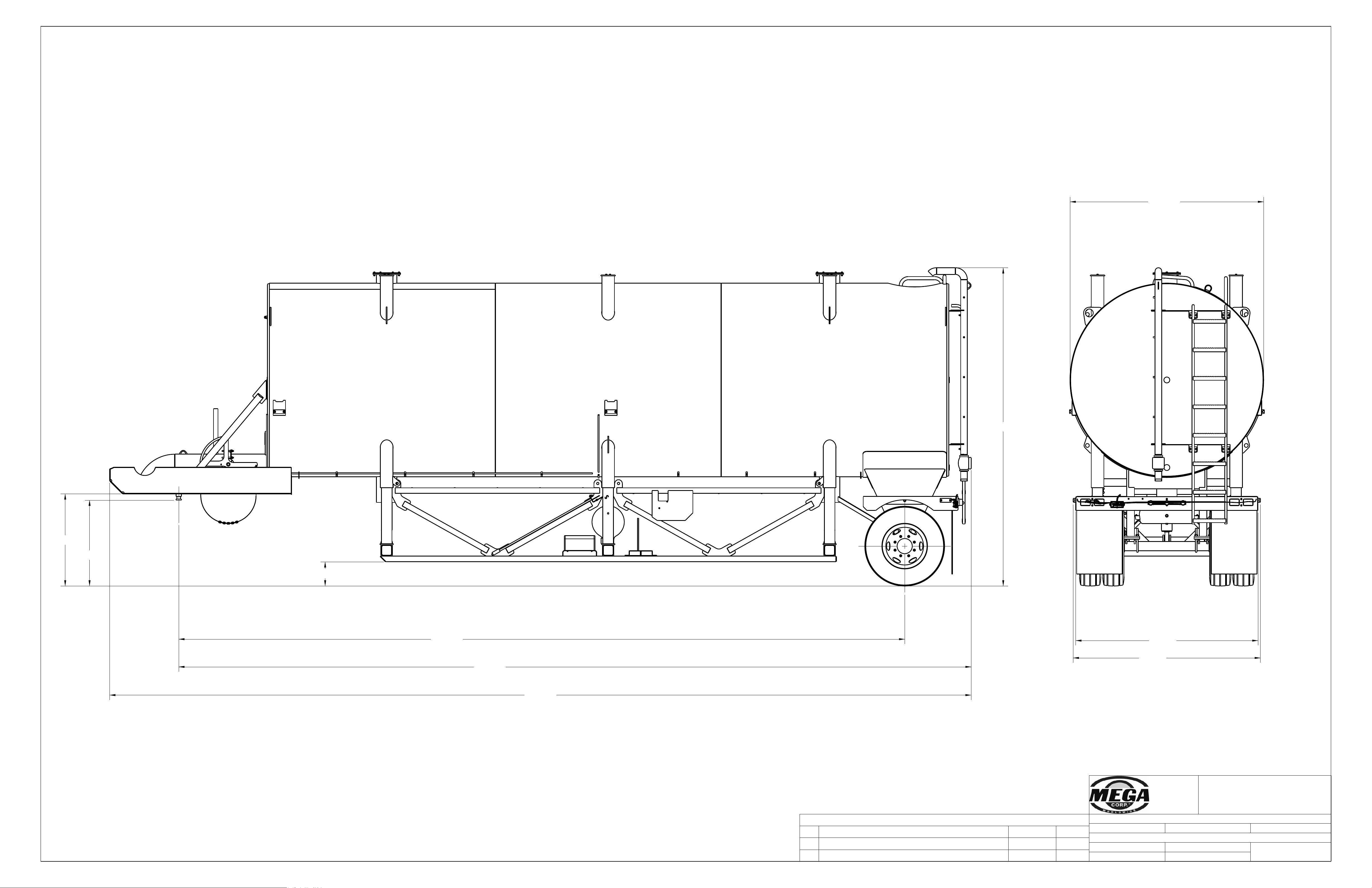
98.62
96.00
102.00
167.65
417.50
453.88
45.22
48.54
382.50
12.75
700 Osuna Rd. N.E.
P.O. Box 26146
Albuquerque, NM 87125
(505) 345-2661
THIS DRAWING IS THE PROPERTY OF MEGA
CORPORATION AND IS USED ONLY IN REFERENCE TO
WORK PROPOSED OR CONTRACTED BY THIS COMPANY.
IT SHALL NOT BE USED FOR ANY OTHER PURPOSE
WITHOUT THE PRIOR CONSENT OF MEGA CORPORATION.
TOLERANCE: UNLESS OTHERWISE SPECIFIED
3 PLACES ± 0.010 2 PLACES ± 0.030 ANGULAR ± 1°
DWG. TITLE: MPT12 SHIPPING DRAWING
SCALE: NTS DATE: Jan-17-17
DWG. NO.
037379
DRAWN BY: DSD SHEET 1 OF 1
REVISIONS
REV DESCRIPTION DATE
ECR
A ADDED SHIPPING WEIGHT APR-19-14 CJD
B NEW DIMS FROM 3D CAD MODEL Jan-17-17 DSD
SHIPPING WEIGHT 24,000 LBS
Appendix A
MPT12
A - 1
Page 41
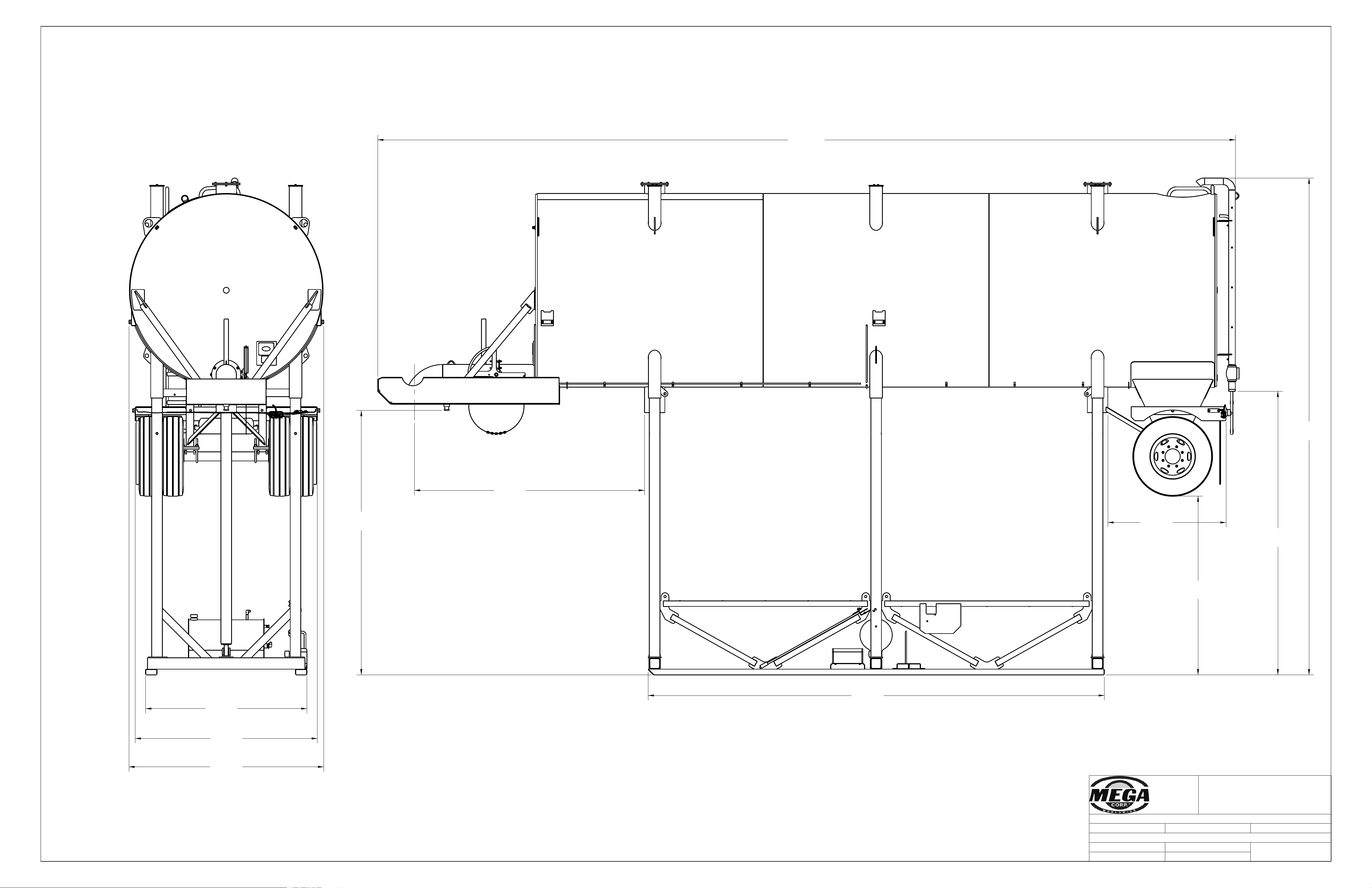
139
[3538]
94
[2393]
262
[6648]
149
[3795]
121
[3078]
103
[2606]
96
[2438]
85
[2159]
62
[1583]
240
[6105]
452
[11478]
700 Osuna Rd. N.E.
P.O. Box 26146
Albuquerque, NM 87125
(505) 345-2661
THIS DRAWING IS THE PROPERTY OF MEGA
CORPORATION AND IS USED ONLY IN REFERENCE TO
WORK PROPOSED OR CONTRACTED BY THIS COMPANY.
IT SHALL NOT BE USED FOR ANY OTHER PURPOSE
WITHOUT THE PRIOR CONSENT OF MEGA CORPORATION.
TOLERANCE: UNLESS OTHERWISE SPECIFIED
3 PLACES ± 0.010 2 PLACES ± 0.030 ANGULAR ± 1°
DWG. TITLE: SALES DRAWING, RAISED, 12,000 GALLONS
SCALE: NTS DATE: Jan-18-17
DWG. NO.
051346
DRAWN BY: DSD SHEET 1 OF 2
TANK SHOWN IN RAISED POSITION
Appendix A
MPT12
A - 2
Page 42
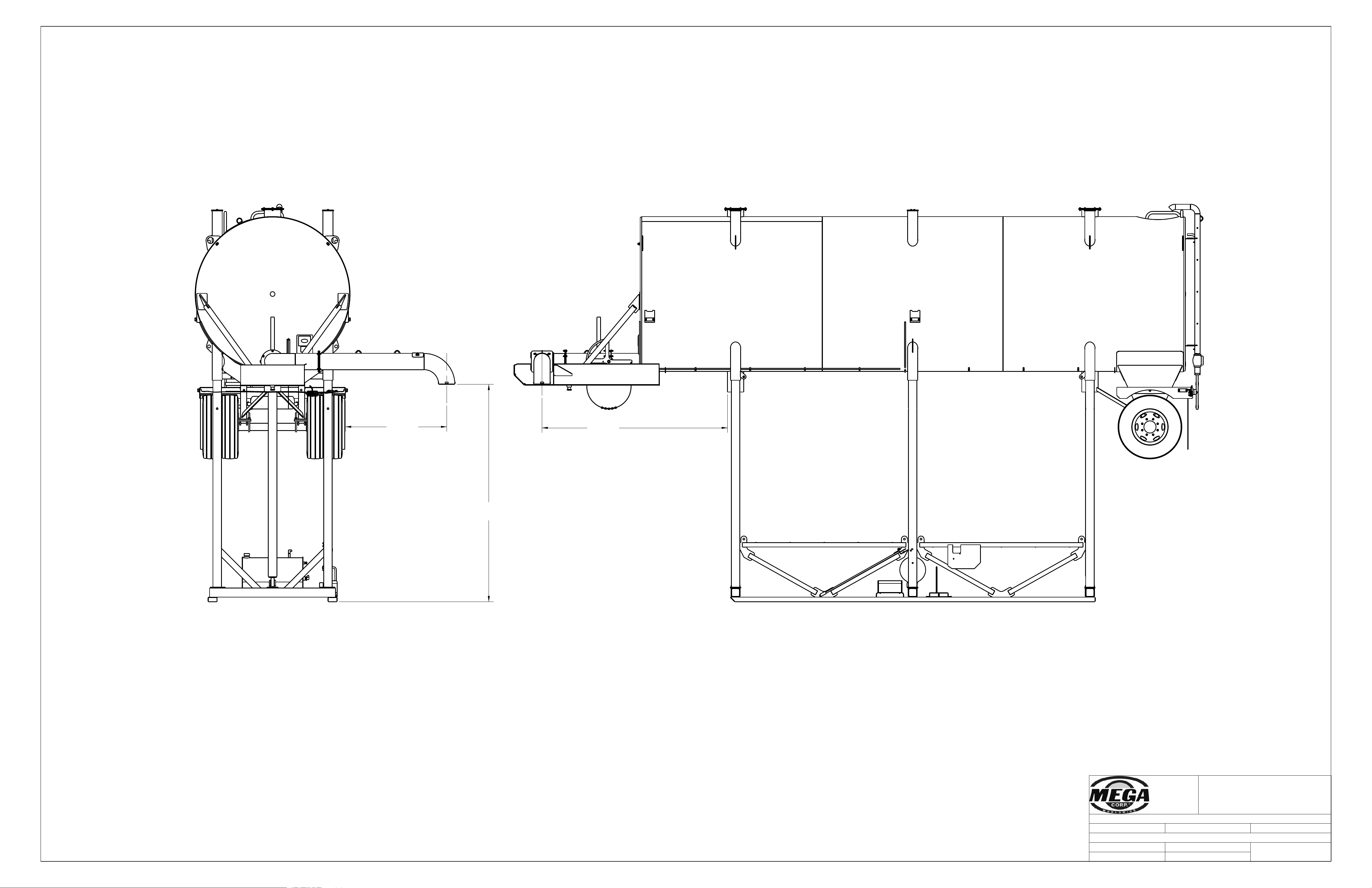
143
[3636]
67
[1694]
122
[3100]
700 Osuna Rd. N.E.
P.O. Box 26146
Albuquerque, NM 87125
(505) 345-2661
THIS DRAWING IS THE PROPERTY OF MEGA
CORPORATION AND IS USED ONLY IN REFERENCE TO
WORK PROPOSED OR CONTRACTED BY THIS COMPANY.
IT SHALL NOT BE USED FOR ANY OTHER PURPOSE
WITHOUT THE PRIOR CONSENT OF MEGA CORPORATION.
TOLERANCE: UNLESS OTHERWISE SPECIFIED
3 PLACES ± 0.010 2 PLACES ± 0.030 ANGULAR ± 1°
DWG. TITLE: SALES DRAWING, RAISED, 12,000 GALLONS
SCALE: NTS DATE: Jan-18-17
DWG. NO.
051346
DRAWN BY: DSD SHEET 2 OF 2
SIDE DISCHARGE OPTION SHOWN
ALL DIMENSIONS SAME AS STANDARD TANK
EXCEPT WHERE INDICATED
Appendix A
MPT12
A - 3
Page 43
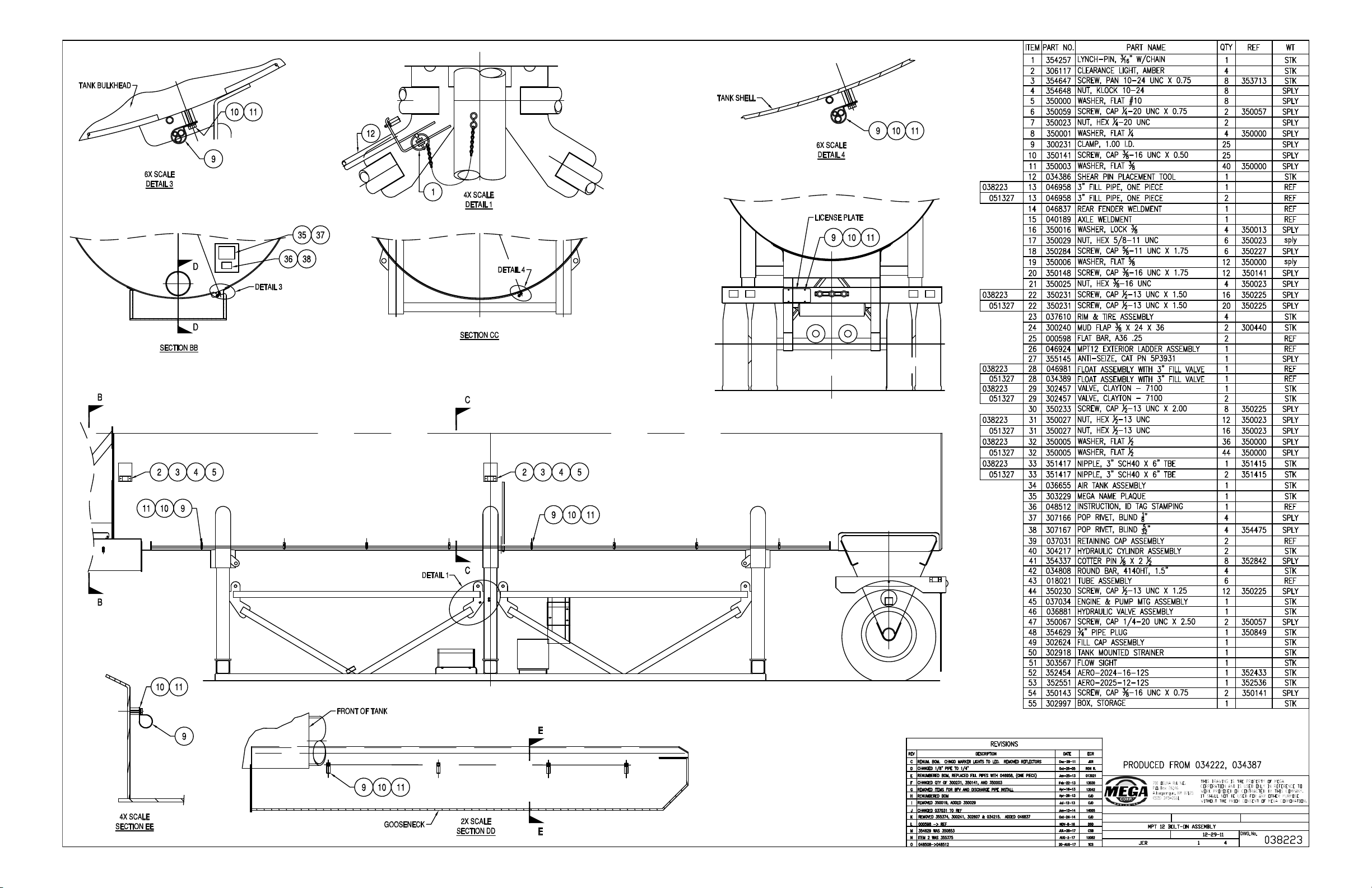
SHEET OF DRAWN BY:
2 PLACES ± 0.03
TOLERANCE: UNLESS OTHERWISE SPECIFIED
3 PLACES ± 0.010
DRAWING TITLE:
SCALE:
DATE:
ANGULAR ± 1°
NONE
HYDRAULIC
CONTROL
VALVE
ENGINE
~
BOX
TOOL
Appendix A
MPT12
A - 4
Page 44
Appendix A
MPT12
A - 5
Page 45
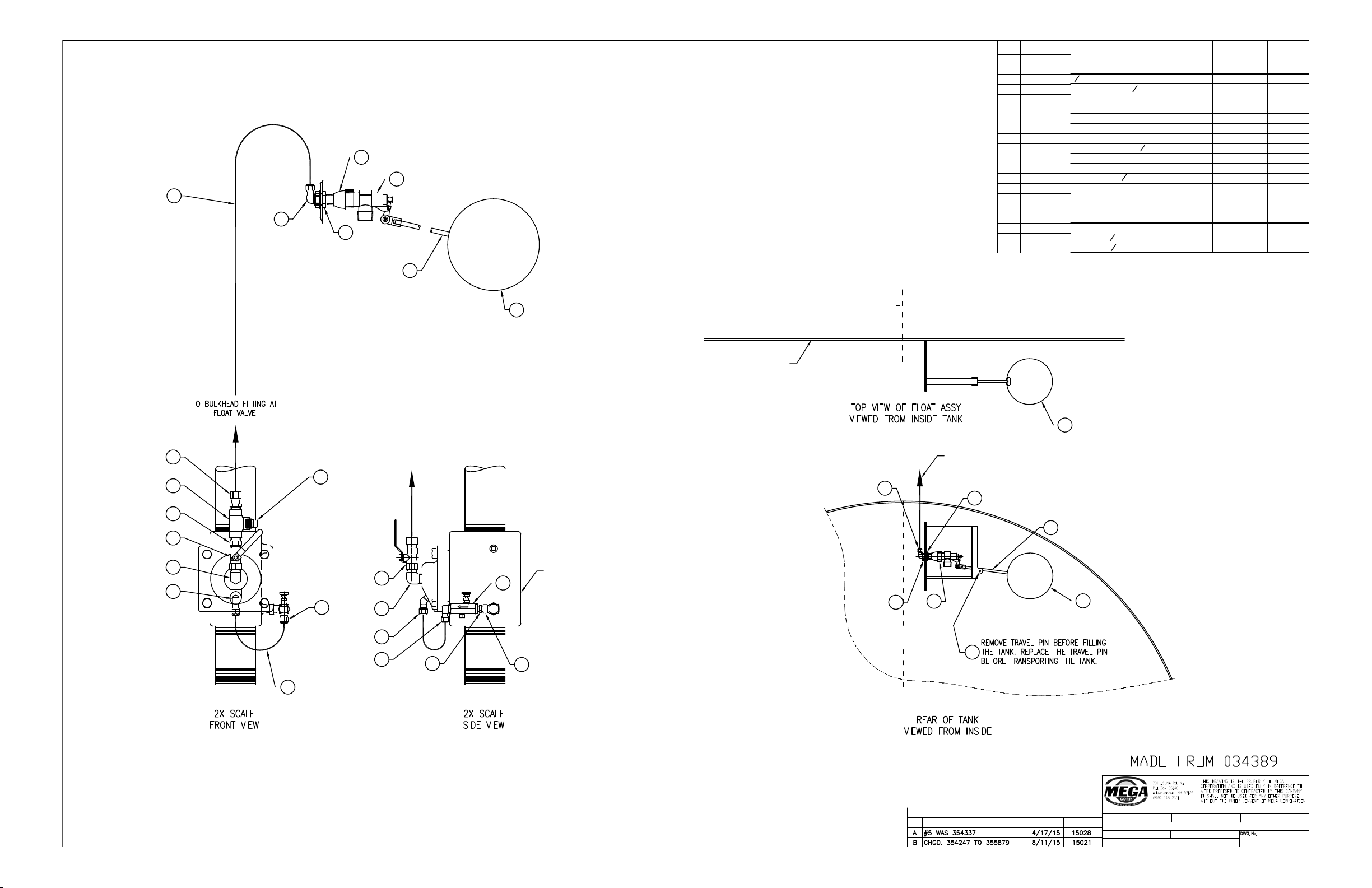
ITEM PART NO. PART NAME
QTY
REF NO. IND. WT.
1
354259 BALL FLOAT
1
STK
2
303202
FLOAT VALVE−1" BRASS
1
STK
3 354422
3
8
" ALL−THREAD X 7.00
1
STK
4
352706 BELL REDUCER
1
2
" FPT TO 1" FPT
1
STK
5 355879 LYNCH PIN
1
STK
6 354258
CLAMPING STUD
1
STK
7
351088 AIR FTG 1469X8
1
STK
8 351082
AIR FTG 1469X6 1 STK
9
352892
AERO FTG 2089−6−4S
1
STK
10 300283
CONTROL VALVE,
1
4
" NPT
1STK
11
351124
AIR FTG 1480X6
1
STK
12
352467
AERO FTG 2083−4−4S 1 STK
13 301299
BALL VALVE,
1
2
" FPT
1
STK
14
352472
AERO 2083−8−8S 1 STK
15 354037
AERO 2085−8−8S
1
STK
16 352858
AERO 2090−8−8S 1 STK
17
351072
AIR FTG 1468X8X8
1
STK
18 350852
PLUG, PIPE 1/2" SQ. HEAD
1
STK
19 351142 TUBING−Ø
1
2
" X 126"
1
STK
20 351141 TUBING−Ø
3
8
" X 12"
2
STK
SHEET OF DRAWN BY:
2 PLACES ± 0.03
TOLERANCE: UNLESS OTHERWISE SPECIFIED
3 PLACES ± 0.010
DRAWING TITLE:
SCALE:
DATE:
ANGULAR ± 1°
NONE
046981
11
CJD
Feb−01−13
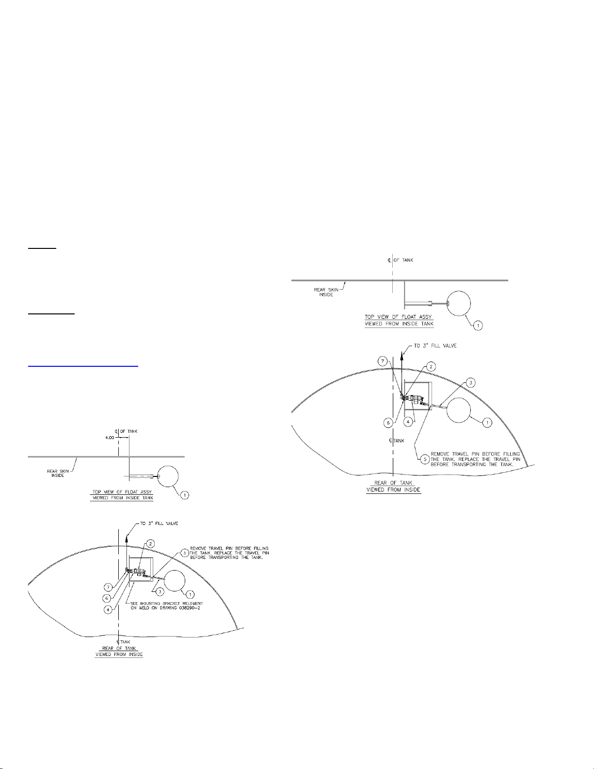
FLOAT ASSEMBLY WITH 3" FILL VALVE
1
2
6
7
19
4
3
9
12
10
11
20
11
15
15
13
14
16
17
18
13
8
8
TANK
1
1
L
C
5
C OF TANK
2
3
7
6
4
REAR SKIN
INSIDE
TO 3" FILL VALVE
3" FILL VALVE REF
DESCRIPTION
REV
REVISIONS
DATE
APPROVED
Appendix A
MPT12
A - 6
Page 46
Appendix A
MPT12
A - 7
Page 47
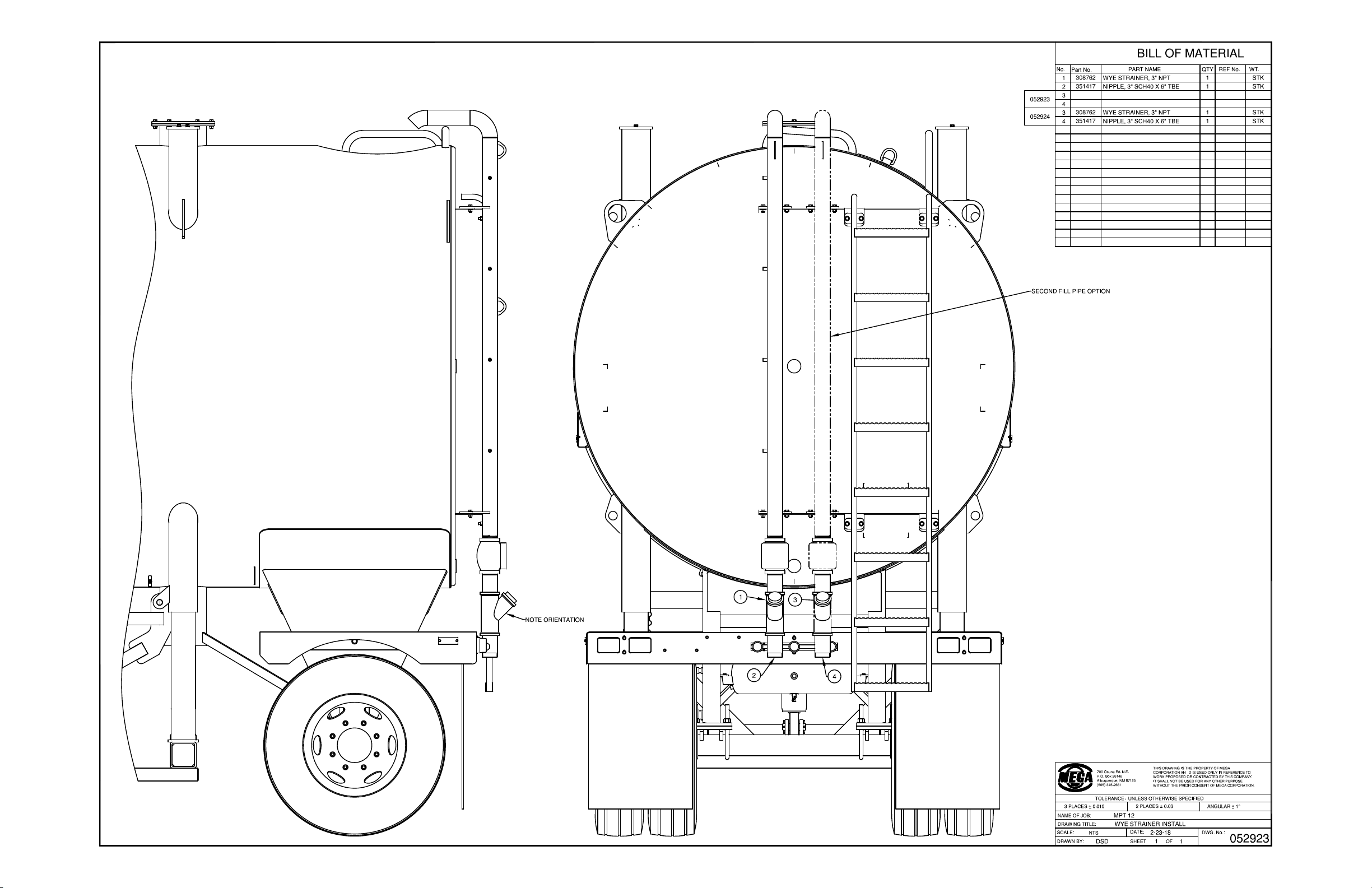
*IF EQUIPPED
Appendix A
MPT12
A - 8
Page 48
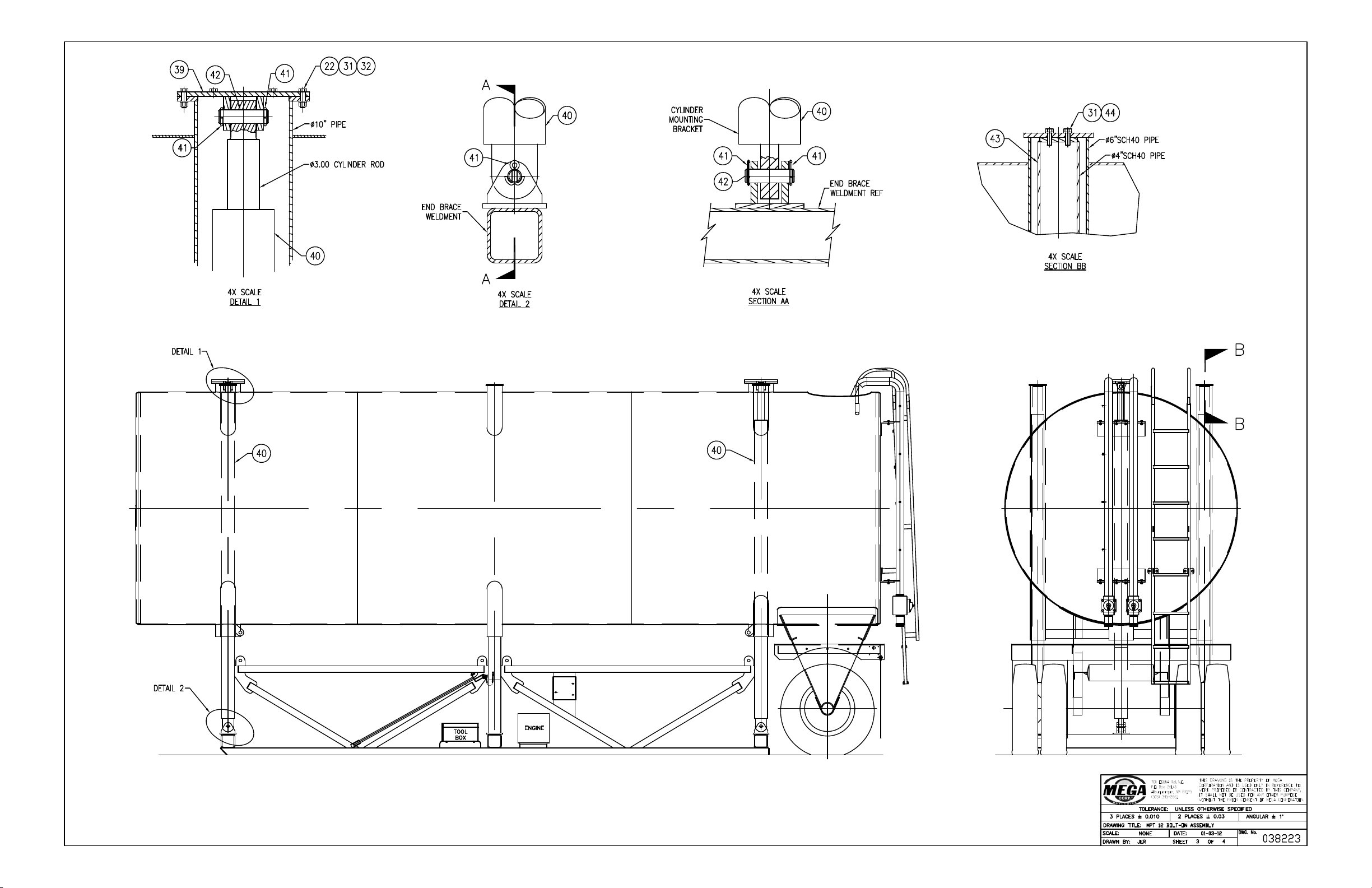
Appendix A
MPT12
A - 9
Page 49
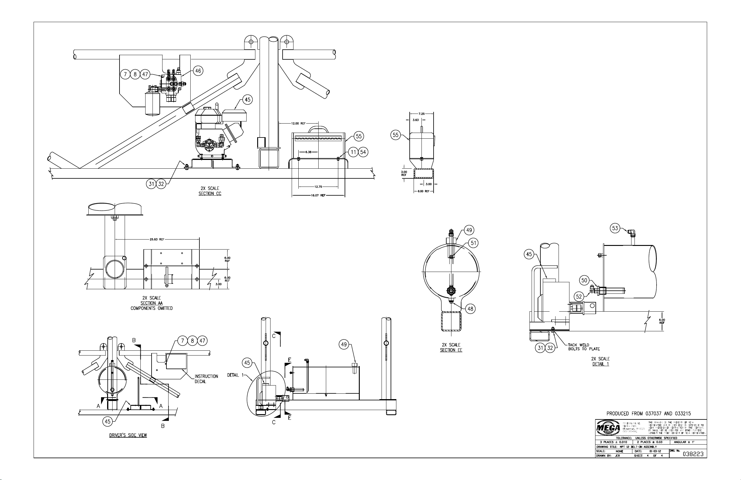
Appendix A
MPT12
A - 10
Page 50
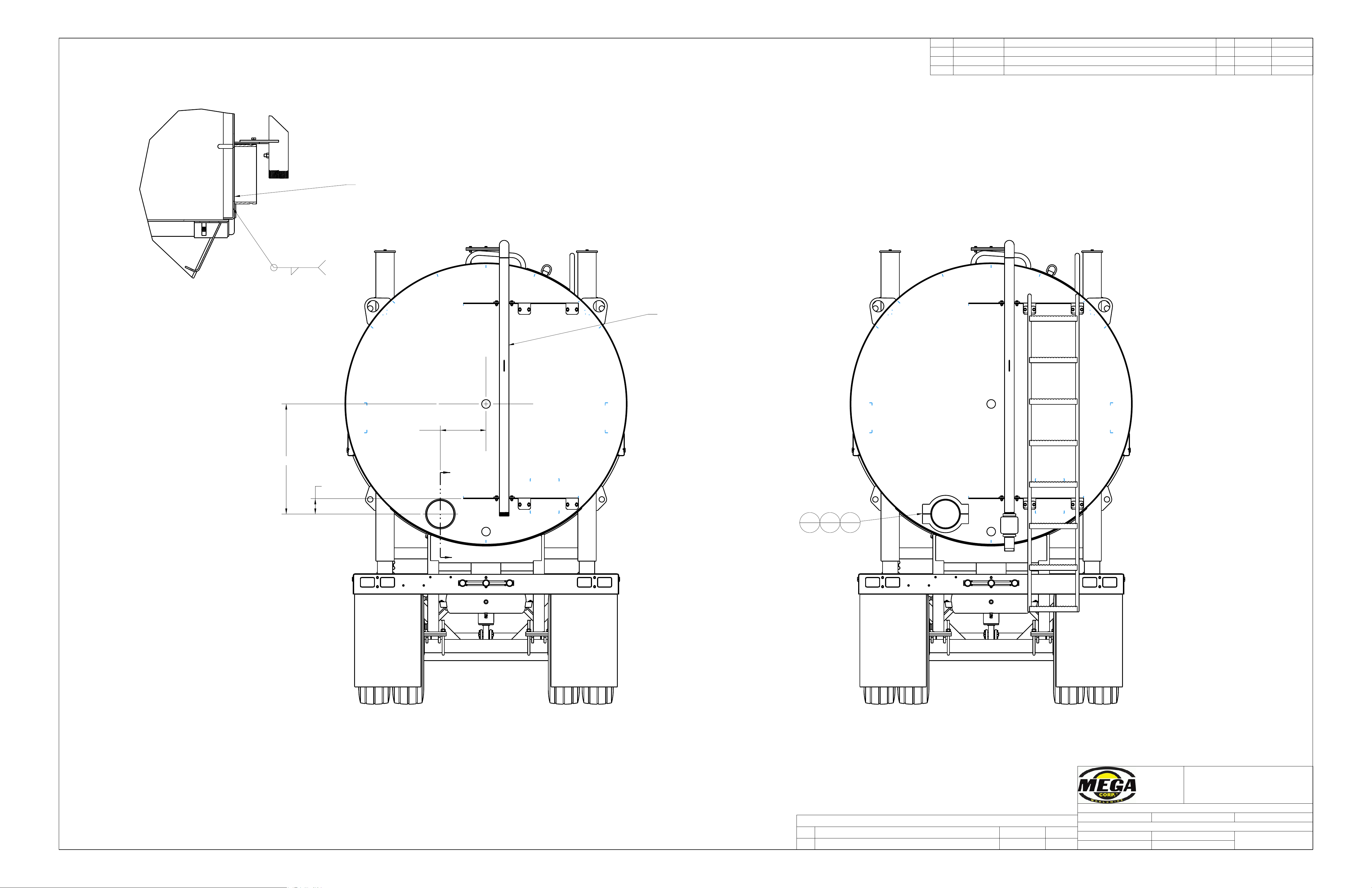
G
G
16.50
39.78
(5.53)
ITEM PART NO. PART NAME QTY REF NO. IND. WT.
1 308195 COUPLING, GROOVED 10" 1 STK
2 308196 CAP, GROOVED COUPLING, 10" 1 STK
3 308198 10" SCH40 VICTAULIC COUPLING, WELDON 1 STK
700 Osuna Rd. N.E.
P.O. Box 26146
Albuquerque, NM 87125
(505) 345-2661
THIS DRAWING IS THE PROPERTY OF MEGA
CORPORATION AND IS USED ONLY IN REFERENCE TO
WORK PROPOSED OR CONTRACTED BY THIS COMPANY.
IT SHALL NOT BE USED FOR ANY OTHER PURPOSE
WITHOUT THE PRIOR CONSENT OF MEGA CORPORATION.
TOLERANCE: UNLESS OTHERWISE SPECIFIED
3 PLACES ± 0.010 2 PLACES ± 0.030 ANGULAR ± 1°
DWG. TITLE: MPT12 10IN VICTAULIC CLEANOUT
SCALE: NTS DATE: Feb-07-17
DWG. NO.
051530
DRAWN BY: DSD SHEET 1 OF 1
REVISIONS
REV DESCRIPTION DATE
ECR
A MOVED TO CLEAR BOTH PIPES Apr-24-17 17033
WELDING MODIFICATIONS
FOR THIS OPTION
ASSEMBLY PORTION FOR
THIS OPTION
FILL PIPE MOVED TO RIGHT
HAND SIDE LOCATION
SECTION G-G
SCALE 0.150
BURN 9.75" HOLE IN REAR HEAD
WP1 TYP
.25
1
1
2
1
3
1
Appendix A
MPT12
A - 11
*IF EQUIPPED
Page 51
C
C
D
D
1.94
700 Osuna Rd. N.E.
P.O. Box 26146
Albuquerque, NM 87125
(505) 345-2661
THIS DRAWING IS THE PROPERTY OF MEGA
CORPORATION AND IS USED ONLY IN REFERENCE TO
WORK PROPOSED OR CONTRACTED BY THIS COMPANY.
IT SHALL NOT BE USED FOR ANY OTHER PURPOSE
WITHOUT THE PRIOR CONSENT OF MEGA CORPORATION.
TOLERANCE: UNLESS OTHERWISE SPECIFIED
3 PLACES ± 0.010 2 PLACES ± 0.030 ANGULAR ± 1°
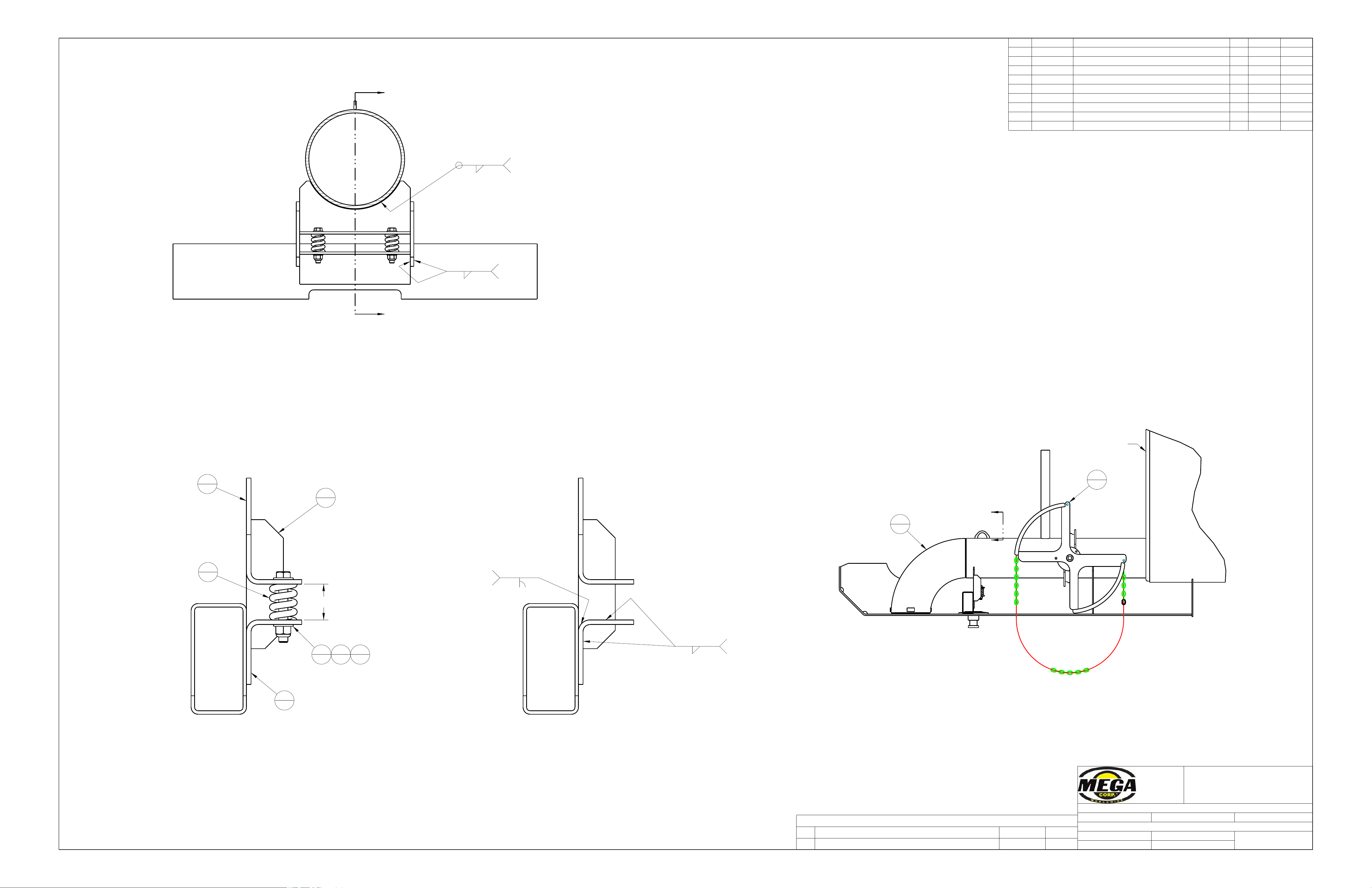
DWG. TITLE: STANDARD DISCHARGE OPTION
SCALE: NTS DATE: Apr-16-13
DWG. NO.
047165
DRAWN BY: CJD SHEET 1 OF 1
ITEM PART NO. PART NAME QTY REF WT
1 031877 PLATE, A36 .38 2 REF
2 037227 MPT12 DRAIN PIPE ASSEMBLY 1 REF
3 039873 PLATE, A36 .25 1 REF
4 039874 PLATE, A36 .25 1 REF
5 047166 MPT12 & 20 BFV AND HANDLE INSTALL 1 REF
6 350005 WASHER, FLAT 1/2 4 SPLY
7 350239 SCREW, CAP 1/2-13 UNC X3.50 2 SPLY
8 352677 NUT, LOCK 1/2-13 2 352583 SPLY
9 354591 SPRING, 13/16 ID X 2.50 2 300180 STK
REVISIONS
REV DESCRIPTION DATE
ECR
A
031877, 037227, 039873, & 039874 TO REF.
Jan-13-14 14005
NOTE 1
PRE-ASSEMBLE ITEMS 039873 & 039874 WITH SPRING.
COMPRESS SPRING WITH 1/2" BOLT AND LOCKNUT, (ITEMS
350239 AND 352677). MAKE THE SPACE 1.94". WELD
ITEM 039873 TO 10" PIPE. BE SURE THAT ITEM 039874
IS IN CONTACT WITH ITEM 037275 BEFORE WELDING.
FRONT OF TANK
SECTION C-C
COMPONENTS OMITTED
SEE NOTE 1
SEE NOTE 1
SECTION D-D
SECTION D-D
COMPONENTS OMITTED
SEE NOTE 1
WP1
.25
WP1
.25
WP1
.25
WP1
.19
2
1
5
1
1
2
3
1
4
1
6
4
9
2
7
2
8
2
Appendix A
MPT12
A - 12
Page 52
700 Osuna Rd. N.E.
P.O. Box 26146
Albuquerque, NM 87125
(505) 345-2661
THIS DRAWING IS THE PROPERTY OF MEGA
CORPORATION AND IS USED ONLY IN REFERENCE TO
WORK PROPOSED OR CONTRACTED BY THIS COMPANY.
IT SHALL NOT BE USED FOR ANY OTHER PURPOSE
WITHOUT THE PRIOR CONSENT OF MEGA CORPORATION.
TOLERANCE: UNLESS OTHERWISE SPECIFIED
3 PLACES ± 0.010 2 PLACES ± 0.030 ANGULAR ± 1°
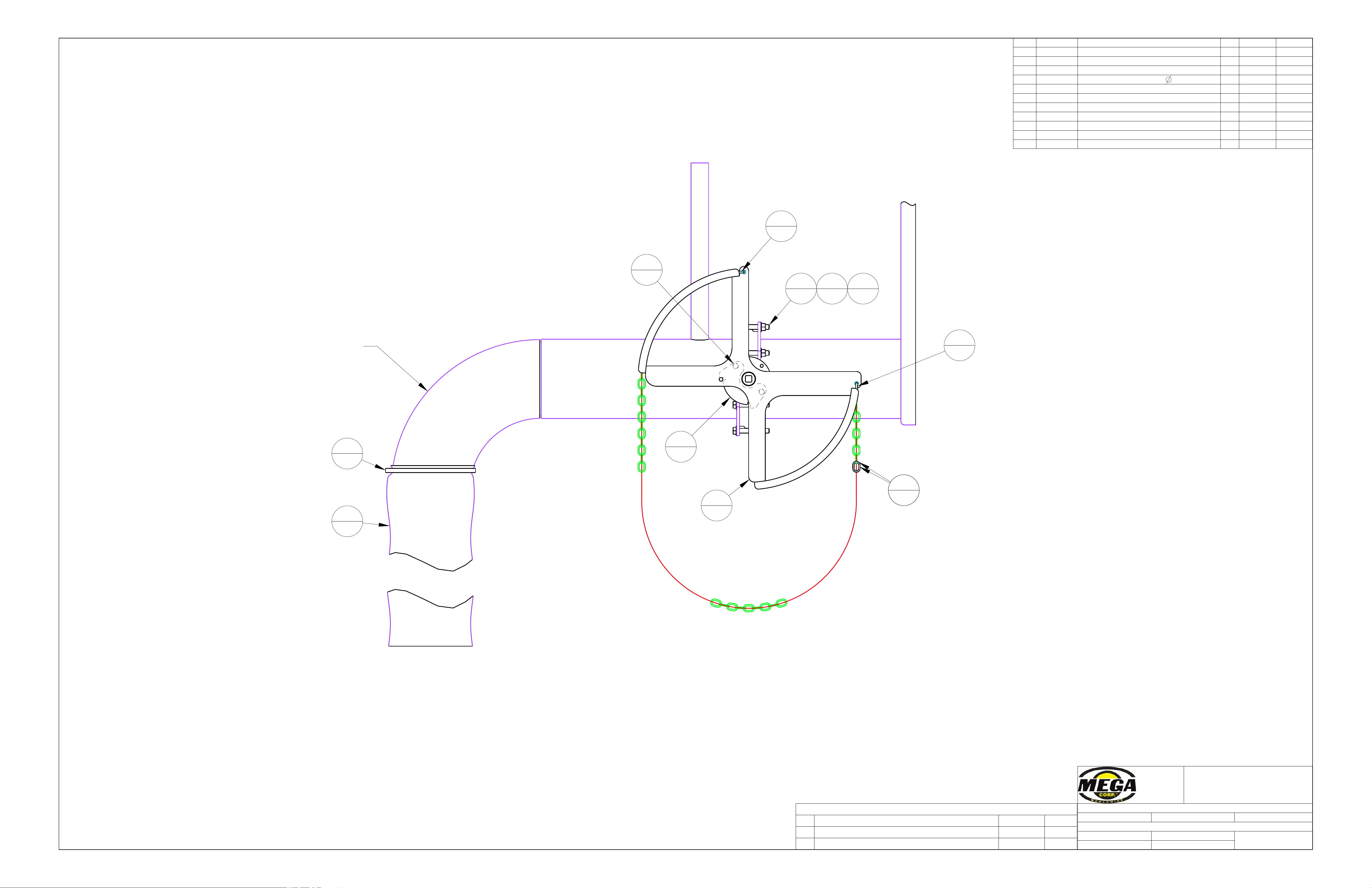
DWG. TITLE: MPT12 & 20 BFV AND HANDLE INSTALL
SCALE: NTS DATE: Apr-17-13
DWG. NO.
047166
DRAWN BY: CJD SHEET 1 OF 1
ITEM PART NO. PART NAME QTY REF WT
1 018408 10" BFV HANDLE ASSEMBLY 1 REF
2 301486 BUTTERFLY VALVE, 10" 1 STK
3 304855 CLAMP, WORM DRIVE 1 SPLY
4 304856 DISCHARGE SOCK, 48 X
11.5" 1 STK
5 350006 WASHER, FLAT 5/8 12 SPLY
6 350029 NUT, HEX 5/8-11 UNC 6 SPLY
7 350231 SCREW, CAP 1/2-13 UNC X1.50 2 SPLY
8 350294 SCREW, CAP 5/8-11 UNC X4.50 6 350277 SPLY
9 353540 UTILITY CHAIN-3/16" X 23'-0" 1 STK
10 353540 UTILITY CHAIN-3/16" X 23'-0" 1 STK
11 354272 COLD SHUT, 1/4" 2 STK
REVISIONS
REV DESCRIPTION DATE
ECR
A REMOVED 350148 Oct-24-14 CJD
B 018408 -> REF Nov-04-16 DSD
TO FACILITATE STOP ADJUSTMENT
350231, (SCREW, CAP 1/2-13 X 1.50)
REPLACE INCLUDED1/2" BOLTS WITH
DISCHARGE OPTION.
PIPE DEPENDS ON
AS REFERENCE. ACTUAL
DISCHARGE PIPE SHOWN
CHAIN AND BFV HANDLE
ARE SHOWN WITH BFV
IN CLOSED POSITION.
1
1
2
1
3
1
7
2
8
6
11
1
11
1
4
1
9110
1
5
12
6
6
Appendix A
MPT12
A - 13
Page 53
ITEM PART NO. PART NAME QTY REF NO. IND. WT.
1 051723 10" BFV HANDLE ASSEMBLY 1 REF
2 051724 MPT12 REMOTE ACTUATOR WELDON 1 REF
3 051833-01 WIRE ROPE, 3/16"x12' 1 308305 STK
4 051833-02 TUBING, NYLON, AIR 3/8" X 96" 1 351141 STK
5 051834 MPT12 REMOTE ACTUATION WIRING 1 REF
6 303056 CLAMP, 0.38 I.D. 2 SPLY
7 303691 STRAIN RELIEF 1/2" SMALL 1 STK
8 308247 LINEAR ACTUATOR 6" TRAVEL 1 STK
9 308299 CLEVIS PIN, 3/8" OD 3-3/4" USABLE LENGTH 1 STK
10 308300 SPRING, 3" LONG, 0.6" OD 1 STK
11 308302 BATTERY BOX, GROUP 27 1 STK
12 308303 BATTERY GROUP 1 STK
13 308304 COTTER PIN, 1/8X2" 1 STK
14 308306 ALUMINUM FERRULE FOR 3/16" WIRE ROPE 1 STK
15 308309 TIE DOWN STRAP, CAM BUCKLE 1 STK
16 308594 SOLAR CELL, 90W 1 STK
17 350001 WASHER, FLAT 1/4 8 SPLY
18 350023 NUT, HEX 1/4-20 UNC 4 SPLY
19 350061 SCREW, CAP 1/4-20 UNC X1.00 4 350057 SPLY
20 354657 PIN, SAFETY SNAP 1 STK
21 355022 LOCKRING NUT 1/2" 1 STK
22 355455 WASHER, FLAT FENDER 3/8 1 SPLY
700 Osuna Rd. N.E.
P.O. Box 26146
Albuquerque, NM 87125
(505) 345-2661
THIS DRAWING IS THE PROPERTY OF MEGA
CORPORATION AND IS USED ONLY IN REFERENCE TO
WORK PROPOSED OR CONTRACTED BY THIS COMPANY.
IT SHALL NOT BE USED FOR ANY OTHER PURPOSE
WITHOUT THE PRIOR CONSENT OF MEGA CORPORATION.
TOLERANCE: UNLESS OTHERWISE SPECIFIED
3 PLACES ± 0.010 2 PLACES ± 0.030 ANGULAR ± 1°
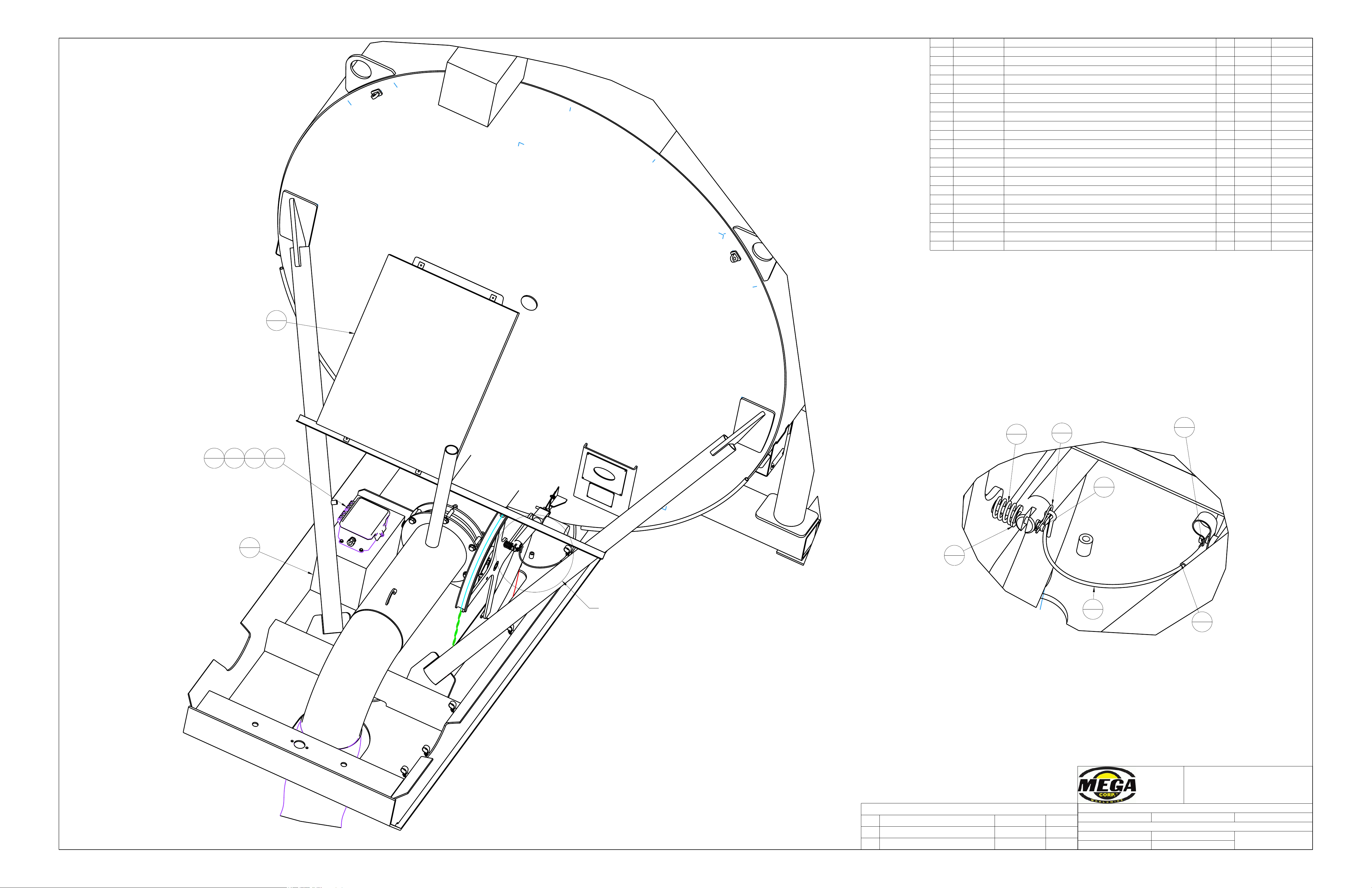
DWG. TITLE: MPT12 REMOTE ACTUATION MECHANICAL ASSEMBLY
SCALE: NTS DATE: May-15-17
DWG. NO.
051833
DRAWN BY: DSD SHEET 1 OF 2
REVISIONS
REV DESCRIPTION DATE APPROVED
A ADDED 308303 Aug-29-17 CSB
B 308307->308594 10-NOV-17 TCS
SEE DETAIL A
DETAIL A
SCALE 0.500
LEAVE 2" OF TUBING
BEYOND P CLAMP
5
1
11
1
16
1
3
1
4
1
6
1
10
1
13
1
9
1
22
1
17
8
18
4
19
4
*IF EQUIPPED
Appendix A
MPT12
A - 14
Page 54
700 Osuna Rd. N.E.
P.O. Box 26146
Albuquerque, NM 87125
(505) 345-2661
THIS DRAWING IS THE PROPERTY OF MEGA
CORPORATION AND IS USED ONLY IN REFERENCE TO
WORK PROPOSED OR CONTRACTED BY THIS COMPANY.
IT SHALL NOT BE USED FOR ANY OTHER PURPOSE
WITHOUT THE PRIOR CONSENT OF MEGA CORPORATION.
TOLERANCE: UNLESS OTHERWISE SPECIFIED
3 PLACES ± 0.010 2 PLACES ± 0.030 ANGULAR ± 1°
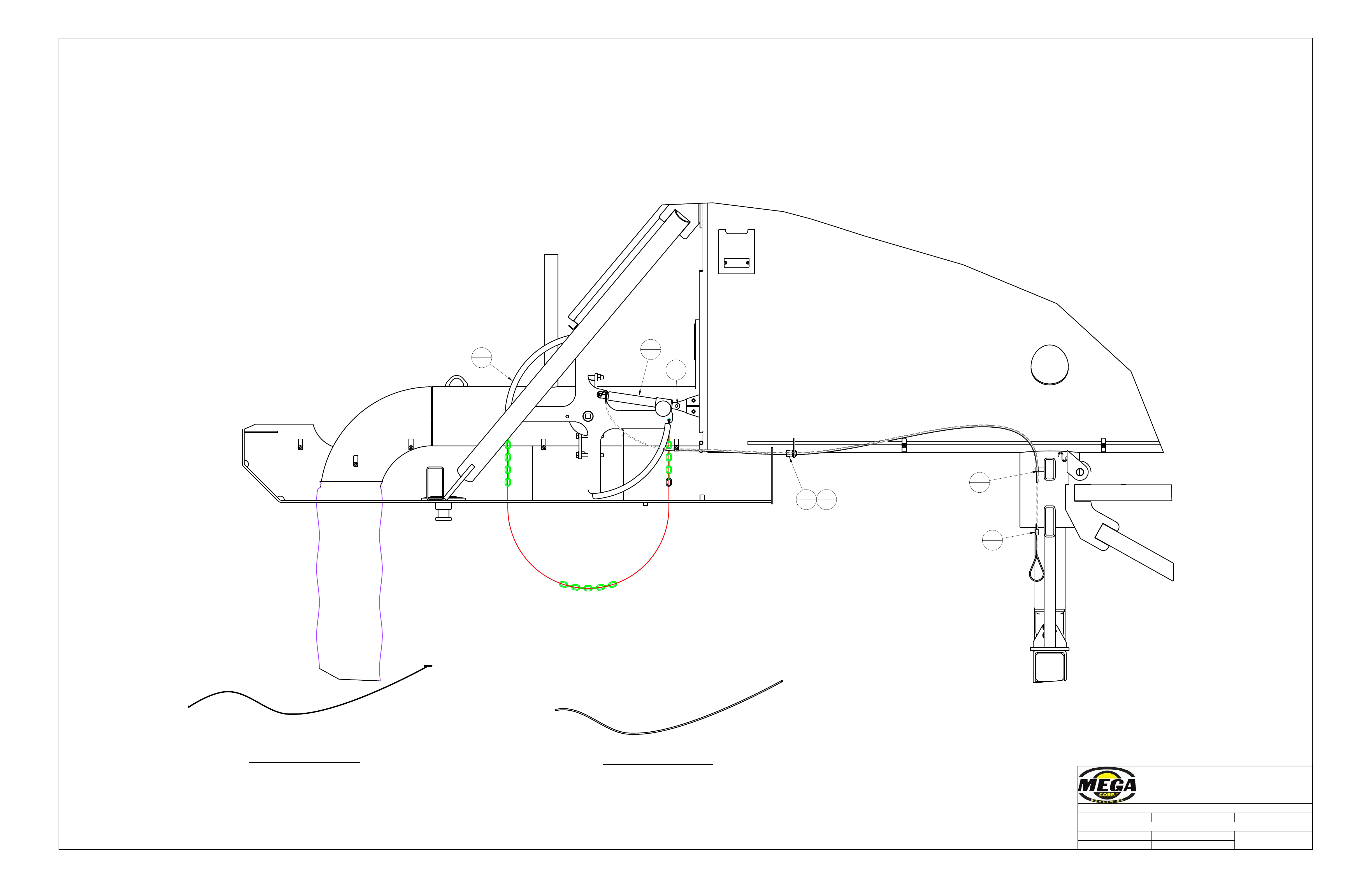
DWG. TITLE: MPT12 REMOTE ACTUATION MECHANICAL ASSEMBLY
SCALE: NTS DATE: May-15-17
DWG. NO.
051833
DRAWN BY: DSD SHEET 2 OF 2
LEAVE 6" LOOP BEFORE
CLAMPING
LEAVE 2" OF TUBING
BEYOND P CLAMP
WIRE ROPE, 3/16"x12'
051833-01
TUBING, NYLON, AIR 3/8" X 96"
051833-02
1
1
7
1
8
1
14
1
20
1
6
1
21
1
Appendix A
MPT12
A - 15
Page 55
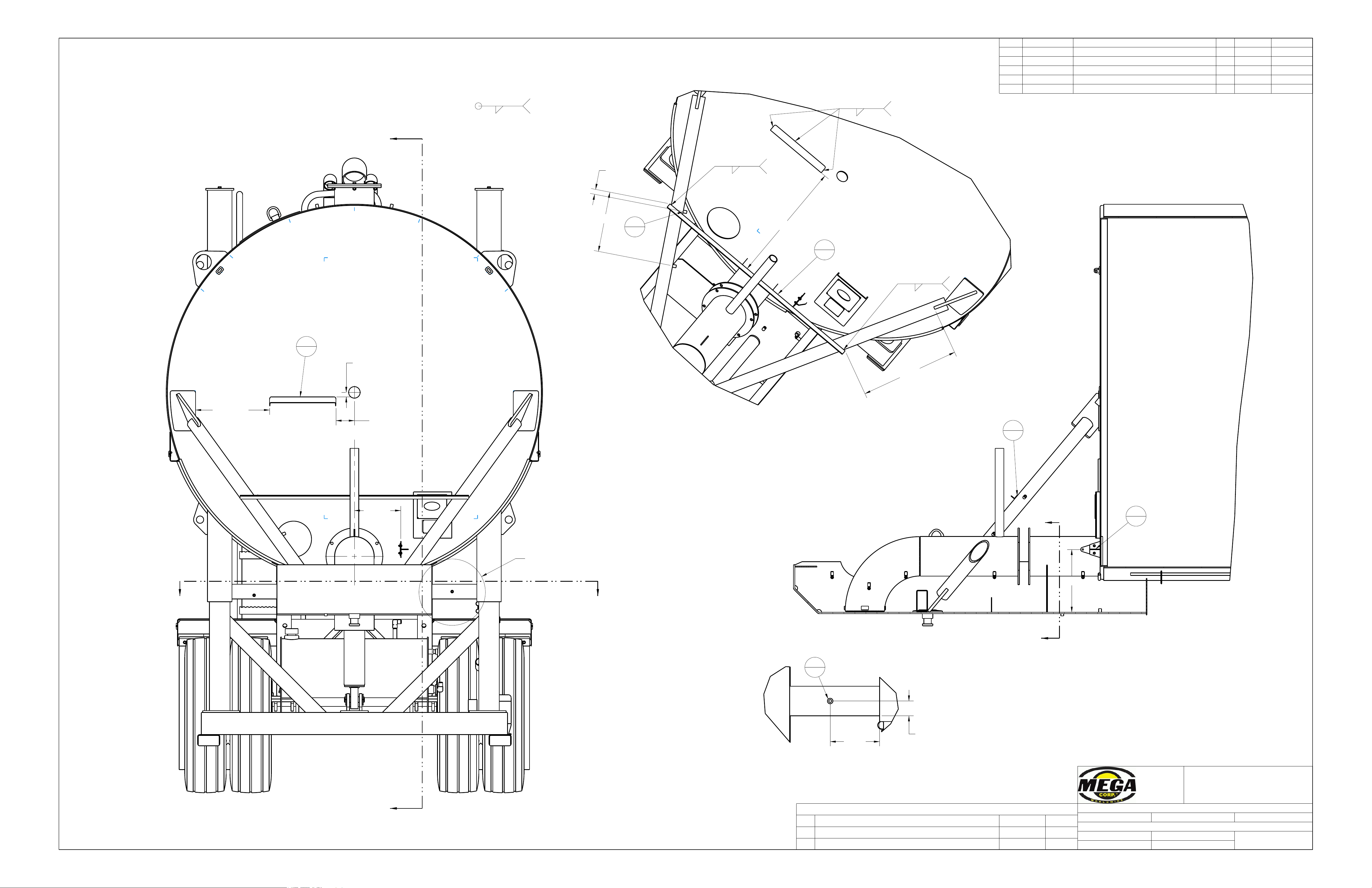
H
H
JJ
K
K
12.53
32.81
6.69
2.00
5.00
1.21
1.35
16.35
17.03
(26.76)
(20.08)
ITEM PART NO. PART NAME QTY REF NO. IND. WT.
1 049008 STANDOFF, M10X1.5 X25MM 7 024634 STK
2 051724-01 ANGLE, 1.25X1.25X.13WT 1 203007
3 051724-02 PLATE, A36 10GA 1 1.5
4 051724-03 PLATE, A36 10GA 1 1.1
5 051725 ACTUATOR BRACKET, WELDON 1 REF
700 Osuna Rd. N.E.
P.O. Box 26146
Albuquerque, NM 87125
(505) 345-2661
THIS DRAWING IS THE PROPERTY OF MEGA
CORPORATION AND IS USED ONLY IN REFERENCE TO
WORK PROPOSED OR CONTRACTED BY THIS COMPANY.
IT SHALL NOT BE USED FOR ANY OTHER PURPOSE
WITHOUT THE PRIOR CONSENT OF MEGA CORPORATION.
TOLERANCE: UNLESS OTHERWISE SPECIFIED
3 PLACES ± 0.010 2 PLACES ± 0.030 ANGULAR ± 1°
DWG. TITLE: REMOTE ACTUATION WELDON
SCALE: NTS DATE: Apr-10-17
DWG. NO.
051724
DRAWN BY: DSD SHEET 1 OF 2
REVISIONS
REV DESCRIPTION DATE
ECR
A ADDED 1 OF 049008 May-19-17 DSD
B MVD -01 FOR NEW PANEL 10-NOV-17 TCS
ALL STANDOFFS
SECTION H-H
SEE DETAIL A
DETAIL A
SCALE 0.200
WP1 TYP
.19
WP1
.19
WP1
.19
WP1
.19
5
1
2
REF
3
1
2
1
1
2
1
1
Appendix A
MPT12
A - 16
Page 56
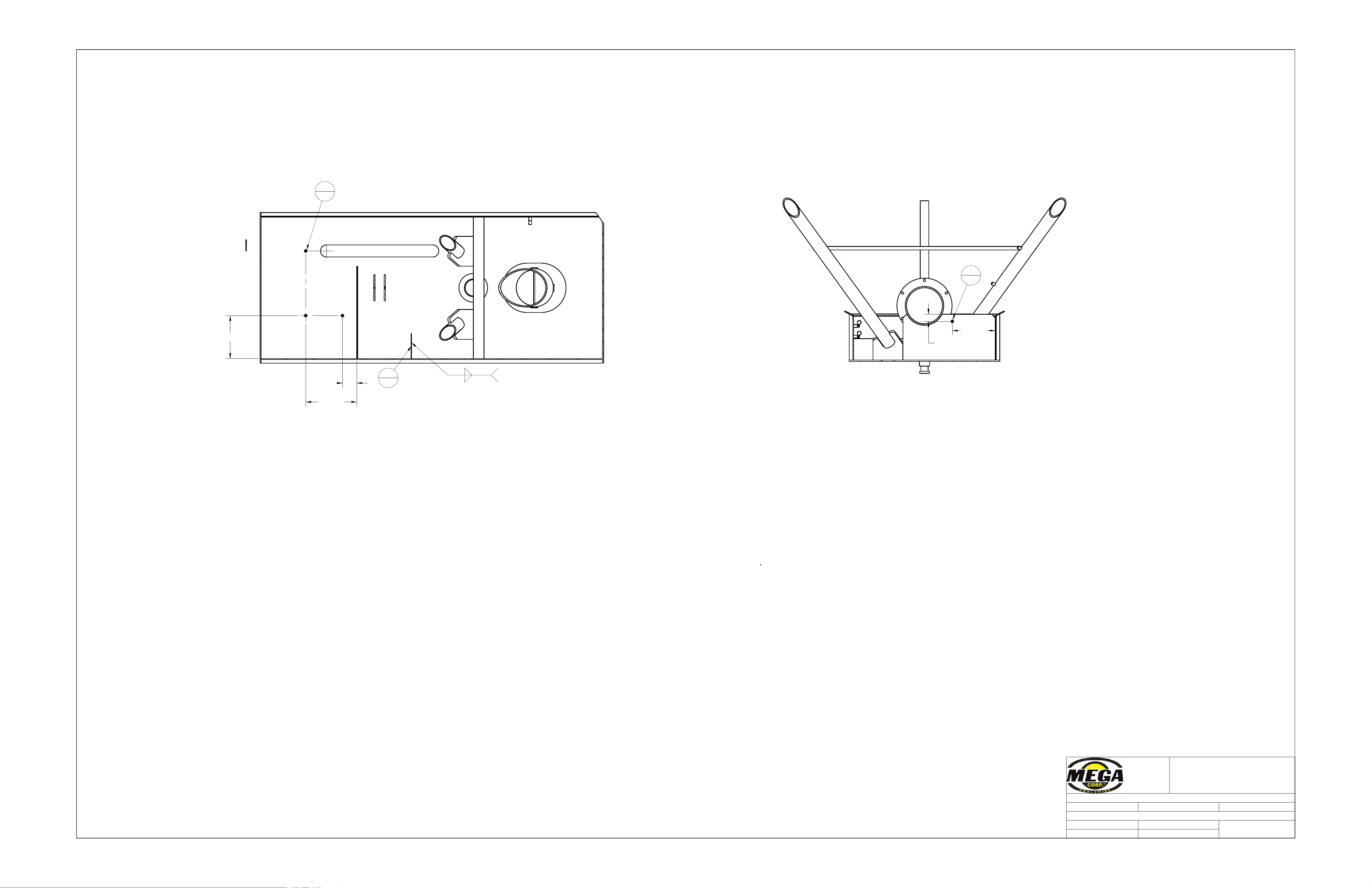
2.00
12.00
4.00
14.25
12.00
700 Osuna Rd. N.E.
P.O. Box 26146
Albuquerque, NM 87125
(505) 345-2661
THIS DRAWING IS THE PROPERTY OF MEGA
CORPORATION AND IS USED ONLY IN REFERENCE TO
WORK PROPOSED OR CONTRACTED BY THIS COMPANY.
IT SHALL NOT BE USED FOR ANY OTHER PURPOSE
WITHOUT THE PRIOR CONSENT OF MEGA CORPORATION.
TOLERANCE: UNLESS OTHERWISE SPECIFIED
3 PLACES ± 0.010 2 PLACES ± 0.030 ANGULAR ± 1°
DWG. TITLE: REMOTE ACTUATOR WELDON
SCALE: NTS DATE: May-11-17
DWG. NO.
051724
DRAWN BY: DSD SHEET 2 OF 2
SECTION J-J
SECTION K-K
WP1
.19
.19
1
3
4
1
1
1
Appendix A
MPT12
A - 17
Page 57
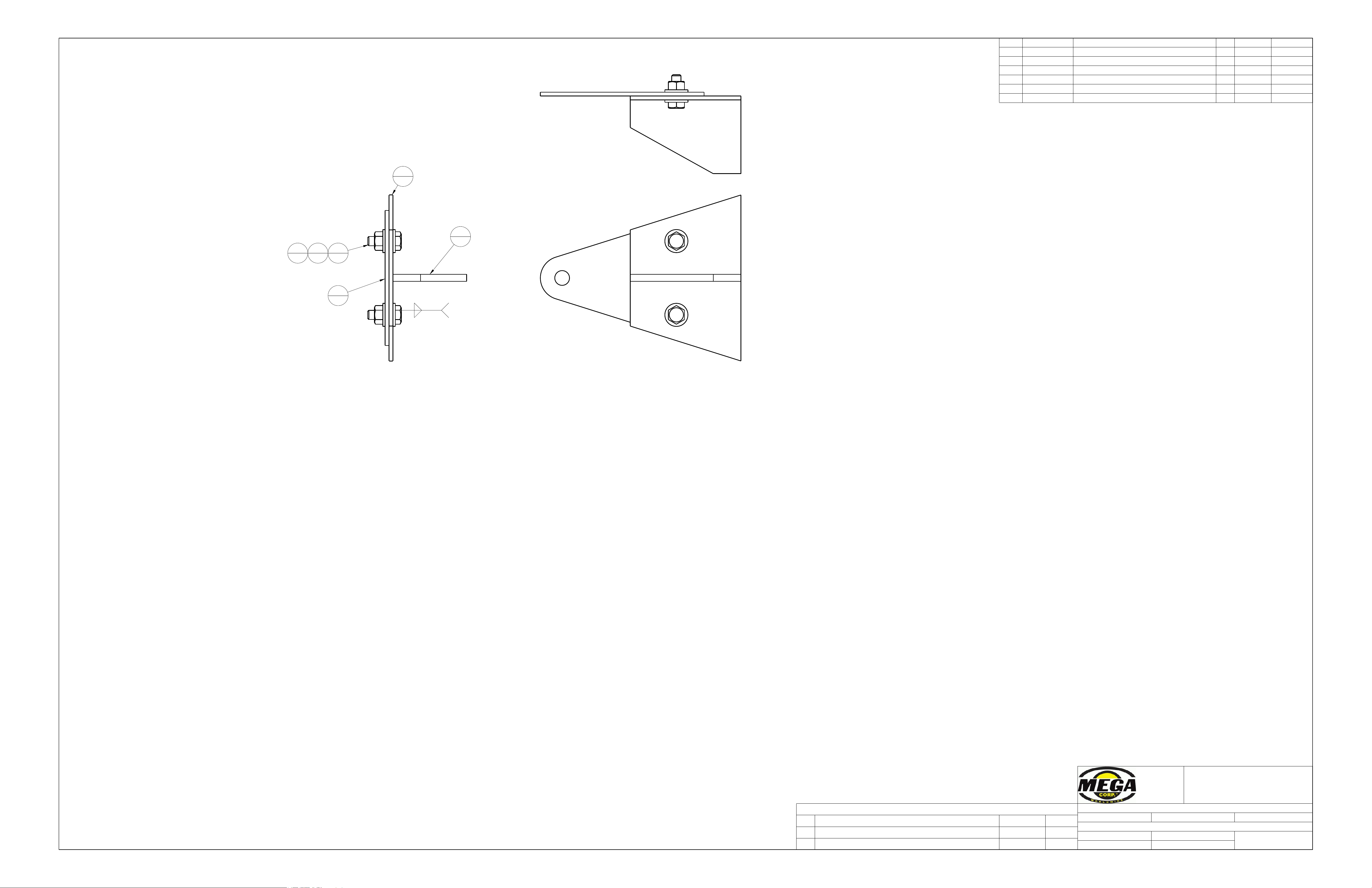
ITEM PART NO. PART NAME QTY REF NO. IND. WT.
1 051725-01 PLATE, A36 12GA 1 0.3
2 051725-02 PLATE, A36 .19 1 0.2
3 051725-03 PLATE, A36 12GA 1 0.3
4 350001 WASHER, FLAT 1/4 4 SPLY
5 350023 NUT, HEX 1/4-20 UNC 2 SPLY
6 350059 SCREW, CAP 1/4-20 UNC X0.75 2 350057 SPLY
700 Osuna Rd. N.E.
P.O. Box 26146
Albuquerque, NM 87125
(505) 345-2661
THIS DRAWING IS THE PROPERTY OF MEGA
CORPORATION AND IS USED ONLY IN REFERENCE TO
WORK PROPOSED OR CONTRACTED BY THIS COMPANY.
IT SHALL NOT BE USED FOR ANY OTHER PURPOSE
WITHOUT THE PRIOR CONSENT OF MEGA CORPORATION.
TOLERANCE: UNLESS OTHERWISE SPECIFIED
3 PLACES ± 0.010 2 PLACES ± 0.030 ANGULAR ± 1°
DWG. TITLE: ACTUATOR BRACKET, WELDON
SCALE: NTS DATE: Apr-10-17
DWG. NO.
051725
DRAWN BY: DSD SHEET 1 OF 1
REVISIONS
REV DESCRIPTION DATE
ECR
A MODIFIED -02, ADDED -03, HARDWARE May-23-17 DSD
B 350058 -> 350059 May-23-17 DSD
WP1
.19
.19
1
1
2
1
3
1
6
2
4
4
5
2
Appendix A
MPT12
A - 18
Page 58
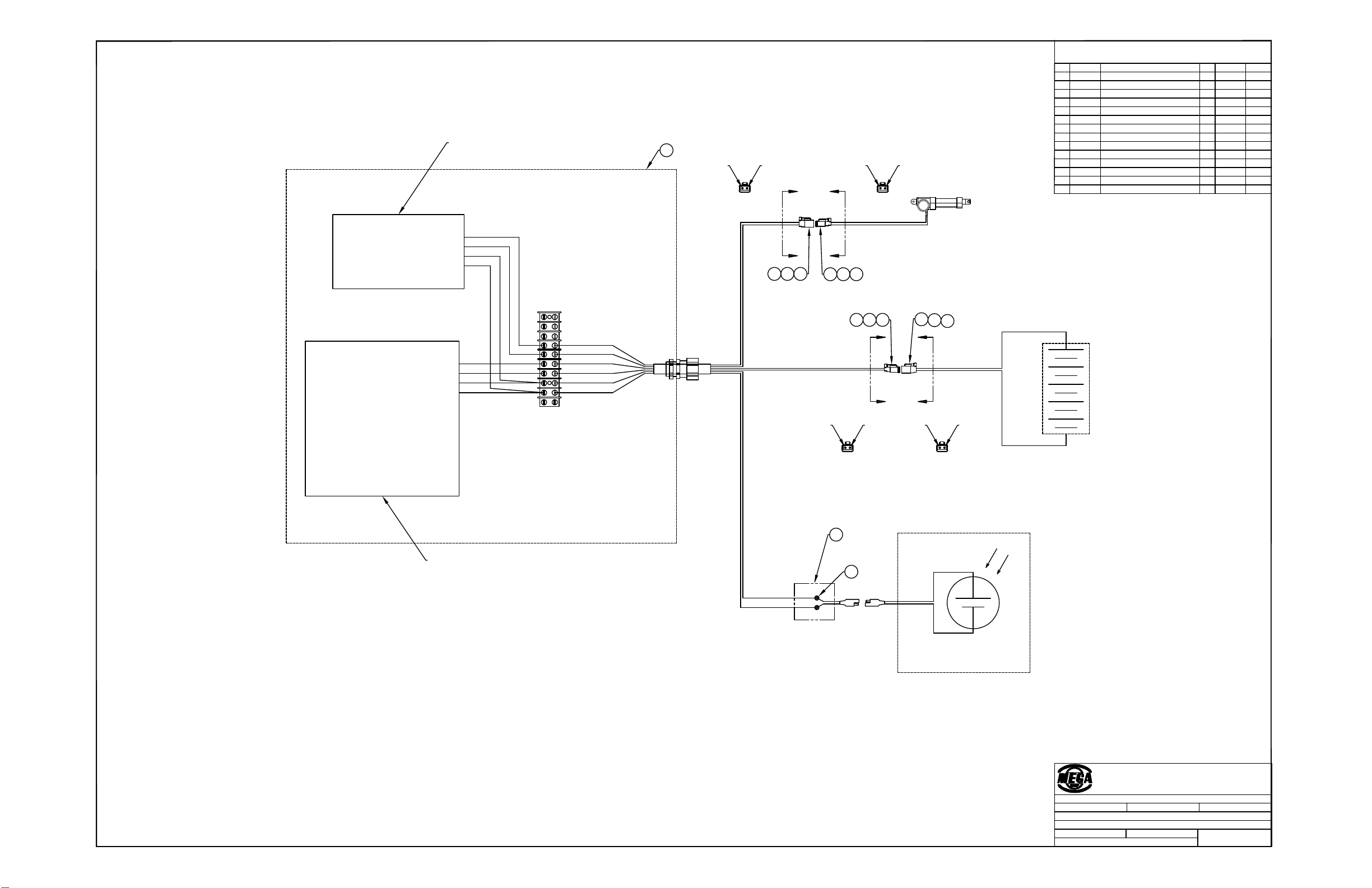
DSD
5−12−17
MPT12 REMOTE ACTUATION
ELECTRICAL INSTALL
051834
NTS
1
5
4
3
2
1
1
DRAWING TITLE:
WT.QTYPART NAME
DATE:
2 PLACES ± 0.03
WITHOUT THE PRIOR CONSENT OF MEGA CORPORATION.
IT SHALL NOT BE USED FOR ANY OTHER PURPOSE
WORK PROPOSED OR CONTRACTED BY THIS COMPANY.
D IS USED ONLY IN REFERENCE TO CORPORATION AN
THIS DRAWING IS THE PROPERTY OF MEGA
DWG. No.:
ANGULAR ± 1°
REF No.
SHEET OF
Part No.
No.
NAME OF JOB:
3 PLACES ± 0.010
SCALE:
DRAWN BY:
TOLERANCE: UNLESS OTHERWISE SPECIFIED
(505) 345−2661
Albuquerque, NM 87125
P.O. Box 26146
700 Osuna Rd. N.E.
BILL OF MATERIAL
051835
ENCLOSURE ASSEMBLY
1
REF
10
9
8
7
6
+
−
ENCLOSURE
306373
2 SPLY
BUTT SPLICE
1
RED
BLACK
RED
BLACK
BATTERY −
BATTERY +
SOLAR PANEL −
SOLAR PANEL +
YELLOW
GREEN
RED
BLACK
BATTERY −
BATTERY +
MOTOR −
MOTOR +
YELLOW
GREEN
BROWN
WHITE
RED
BLACK
A
A
SECTION A−A
(2) BLUE
BROWN (1)
B
B
SECTION B−B
(2) GREEN
YELLOW (1)
D
D
SECTION D−D
(2) BLACK
RED (1)
C
C
SECTION C−C
(2) BLACK
RED (1)
BROWN
WHITE
DEUTSCH RECEPTACLE, 2 CON
DEUTSCH PLUG, 2 CON
SECONDAR Y LOCK, 2 PIN
SECONDARY LOCK, 2 SOCKET
DEUTSCH PIN, 16−10 AWG
DEUTSCH SOCKET, 16−20 AWG
304284
2STK
SPLY
STK
SPLY
SPLY
SPLY
2
2
2
4
4
304285
304384
304385
303366
303380
WIRELESS MOTOR DRIVER
SOLAR CHARGE CONTROLLER
2
3
305272
1 SPLY
HEAT SHRINK, POLYOLEFIN, 3/8
56789
10
6810
5
7
9
SOLAR PANEL
Appendix A
MPT12
A - 19
Page 59
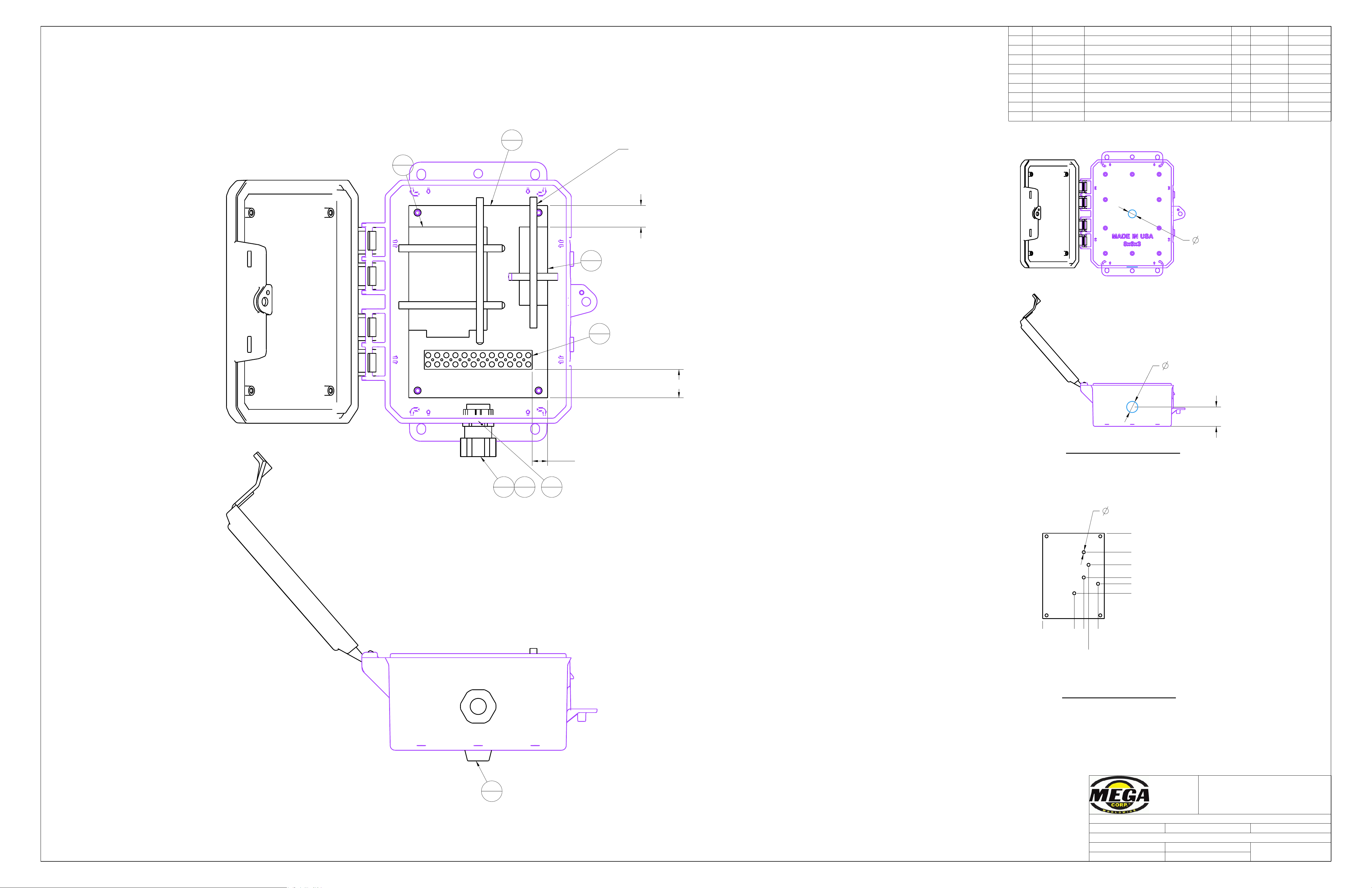
.75
1.00
.55
.88
THRU
.25
5 PLACES
1.50
.00
2.50
3.50
4.00
4.75
2.50
.00
3.25
4.38
3.63
1.54
.63
THRU
ITEM PART NO. PART NAME QTY REF NO. IND. WT.
1 051835-01 ENCLOSURE, MODIFIED 1 308294 DETAIL
2 051835-02 BACKING PLATE, MODIFIED 1 308295 DETAIL
3 303353 TERMINAL STRIP 1 STK
4 305251 CABLE TIE, 12" 5 SPLY
5 305880 CONDENSATION DRAIN, JUNCTION BOX 1 STK
6 308296 SOLAR CHARGE CONTROLLER 1 STK
7 308297 WIRELESS MOTOR DRIVER 1 STK
8 354677 STRAIN RELIEF 1/2" LG. 1 STK
9 355022 LOCKRING NUT 1/2" 1 STK
700 Osuna Rd. N.E.
P.O. Box 26146
Albuquerque, NM 87125
(505) 345-2661
THIS DRAWING IS THE PROPERTY OF MEGA
CORPORATION AND IS USED ONLY IN REFERENCE TO
WORK PROPOSED OR CONTRACTED BY THIS COMPANY.
IT SHALL NOT BE USED FOR ANY OTHER PURPOSE
WITHOUT THE PRIOR CONSENT OF MEGA CORPORATION.
TOLERANCE: UNLESS OTHERWISE SPECIFIED
3 PLACES ± 0.010 2 PLACES ± 0.030 ANGULAR ± 1°
DWG. TITLE: ENCLOSURE ASSEMBLY
SCALE: NTS DATE: May-12-17
DWG. NO.
051835
DRAWN BY: DSD SHEET 1 OF 1
ATTACH COMPONENTS WITH ZIP TIES AS SHOWN
ENCLOSURE, MODIFIED
051835-01
BACKING PLATE, MODIFIED
051835-02
1
1
2
1
3
1
8
1
6
1
7
1
5
1
9
1
Appendix A
MPT12
A - 20
Page 60
C
C
D
D
.13 MAX
4.38
9.00
(.56)
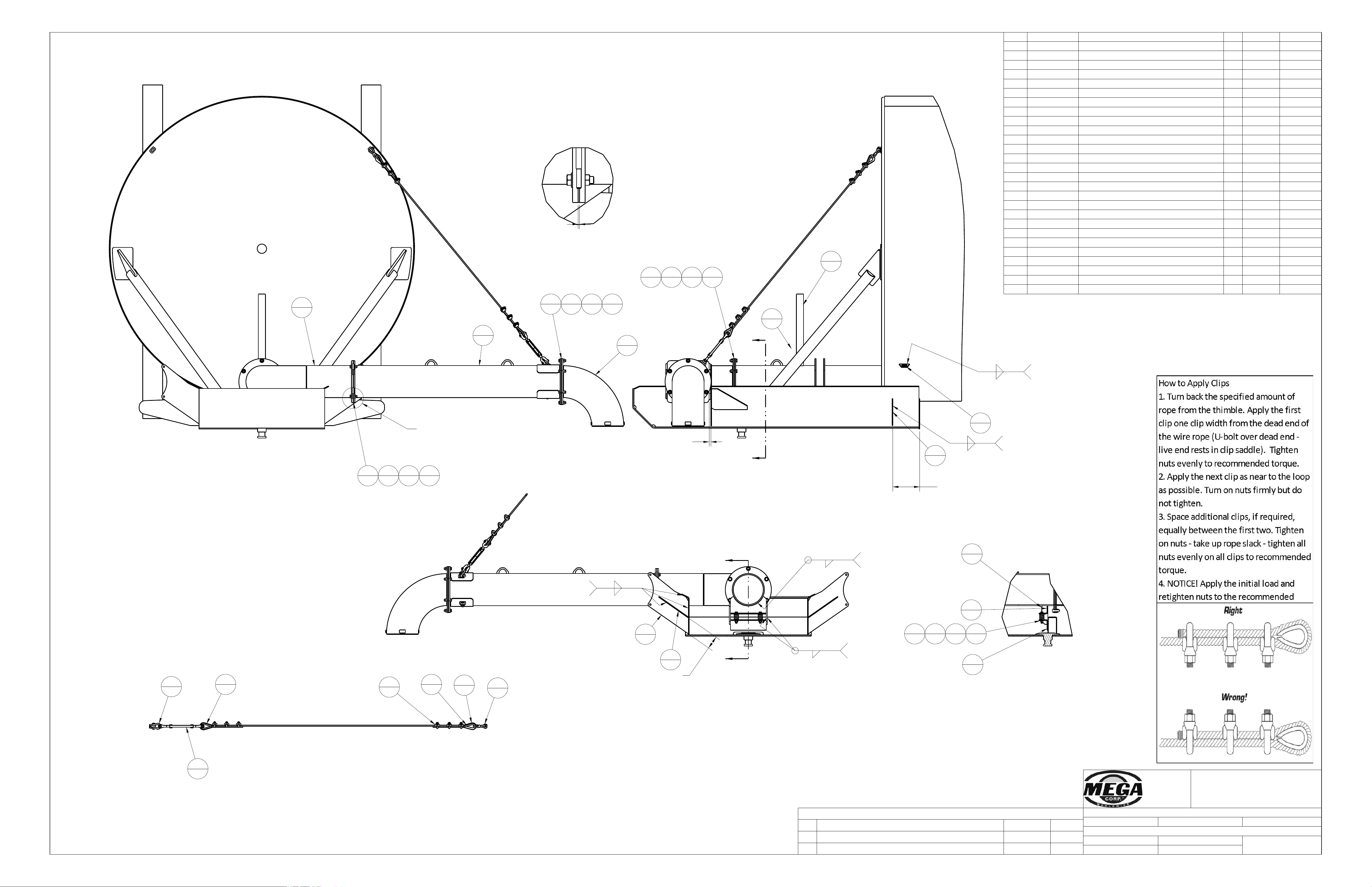
ITEM PART NO. PART NAME QTY REF NO. IND. WT.
1 031877 PLATE, A36 .38 2 REF
2 037294 GASKET, NEOPRENE 1/8" 2 REF
3 039873 PLATE, A36 .25 1 REF
4 039874 PLATE, A36 .25 1 REF
5 047019 MPT12 DRAIN PIPE ASSEMBLY 1 REF
6 047024-01 WIRE ROPE, GALV., .38" X 125" 1 306593 STK
7 047166 MPT12 & 20 BFV AND HANDLE INSTALL 1 REF
8 051328-01 PLATE, A36 .38 2 0.3
9 051328-02 PLATE, A36 .25 2 10.1
10 051328-03 PLATE, A36 .25 2 6.6
11 051328-04 GASKET, NEOPRENE 1/8" 1 0.0
12 051328-05 PLATE, A36 .25 2 10.2
13 051329 DISCHARGE PIPE, FIXED 1 REF
14 051330 DISCHARGE PIPE ASM, MOVING 1 REF
15 051356 ELBOW ASM 1 REF
16 306594 WIRE ROPE CLIP, 3/8" 6 STK
17 306596 WIRE ROPE THIMBLE, 3/8" 2 STK
18 306639 ANCHOR SHACKLE, 3/8" 1 STK
19 306640 JAW & EYE SWIVEL, 3/8" 1 STK
20 306641 TURNBUCKLE 5/8X6 JAW&JAW 1 STK
21 350005 WASHER, FLAT 1/2 4 SPLY
22 350006 WASHER, FLAT 5/8 32 SPLY
23 350029 NUT, HEX 5/8-11 UNC 16 350023 SPLY
24 350239 SCREW, CAP 1/2-13 UNC X3.50 2 SPLY
25 350285 SCREW, CAP 5/8-11 UNC X2.00 16 350277 SPLY
26 352677 NUT, LOCK 1/2-13 2 352583 SPLY
27 354591 SPRING, 13/16 ID X 2.50 2 300180 STK
700 Osuna Rd. N.E.
P.O. Box 26146
Albuquerque, NM 87125
(505) 345-2661
THIS DRAWING IS THE PROPERTY OF MEGA
CORPORATION AND IS USED ONLY IN REFERENCE TO
WORK PROPOSED OR CONTRACTED BY THIS COMPANY.
IT SHALL NOT BE USED FOR ANY OTHER PURPOSE
WITHOUT THE PRIOR CONSENT OF MEGA CORPORATION.
TOLERANCE: UNLESS OTHERWISE SPECIFIED
3 PLACES ± 0.010 2 PLACES ± 0.030 ANGULAR ± 1°
DWG. TITLE: SIDE DISCHARGE ASM, HINGED
SCALE: NTS DATE: Jan-16-17
DWG. NO.
051328
DRAWN BY: DSD SHEET 1 OF 2
REVISIONS
REV DESCRIPTION DATE
ECR
A ADDED -05 Jan-23-17 DSD
B ADDED 051356, MOUNTING HARDWARE Jan-23-17 DSD
COMPONENTS REMOVED FOR CLARITY
NOTE 1: PRE-ASSEMBLE ITEMS 039879 WITH SPRING.
COMPRESS SPRING WITH 1/2" BOLT AND LOCKNUT (ITEMS 350239 & 352677)
MAKE THE SPACE 1.94". WELD ITEM 039873 TO 10" PIPE. BE SURE THAT
ITEM 039874 IS IN CONTACT WITH ITEM 037275 BEFORE WELDING.
NOTE 2: ASSEMBLE DISCHARGE PIPE AND FIT TO GOOSENECK BEFORE WELDING.
SEE DETAIL A
SECTION C-C
SECTION D-D
DETAIL A
SCALE 0.300
WP1 NOTE 2
.19
.19
WP1 TYP NOTE 2
.19
.19
WP1 NOTE 1
.25
WP1
.25
WP1 NOTE 2
.19
.19
13
1
11
1
14
1
15
1
2
1
2
1
5
1
7
1
8
2
12
2
9
2
10
2
1
2
3
1
4
1
21
4
6
1
16
6
17
1
18
1
19
1
20
1
17
1
22
8
25
4
23
4
22
12
23
6
25
6
23
6
25
6
22
12
24
2
26
2
27
2
Appendix A
MPT12
A - 21
*IF EQUIPPED
Page 61
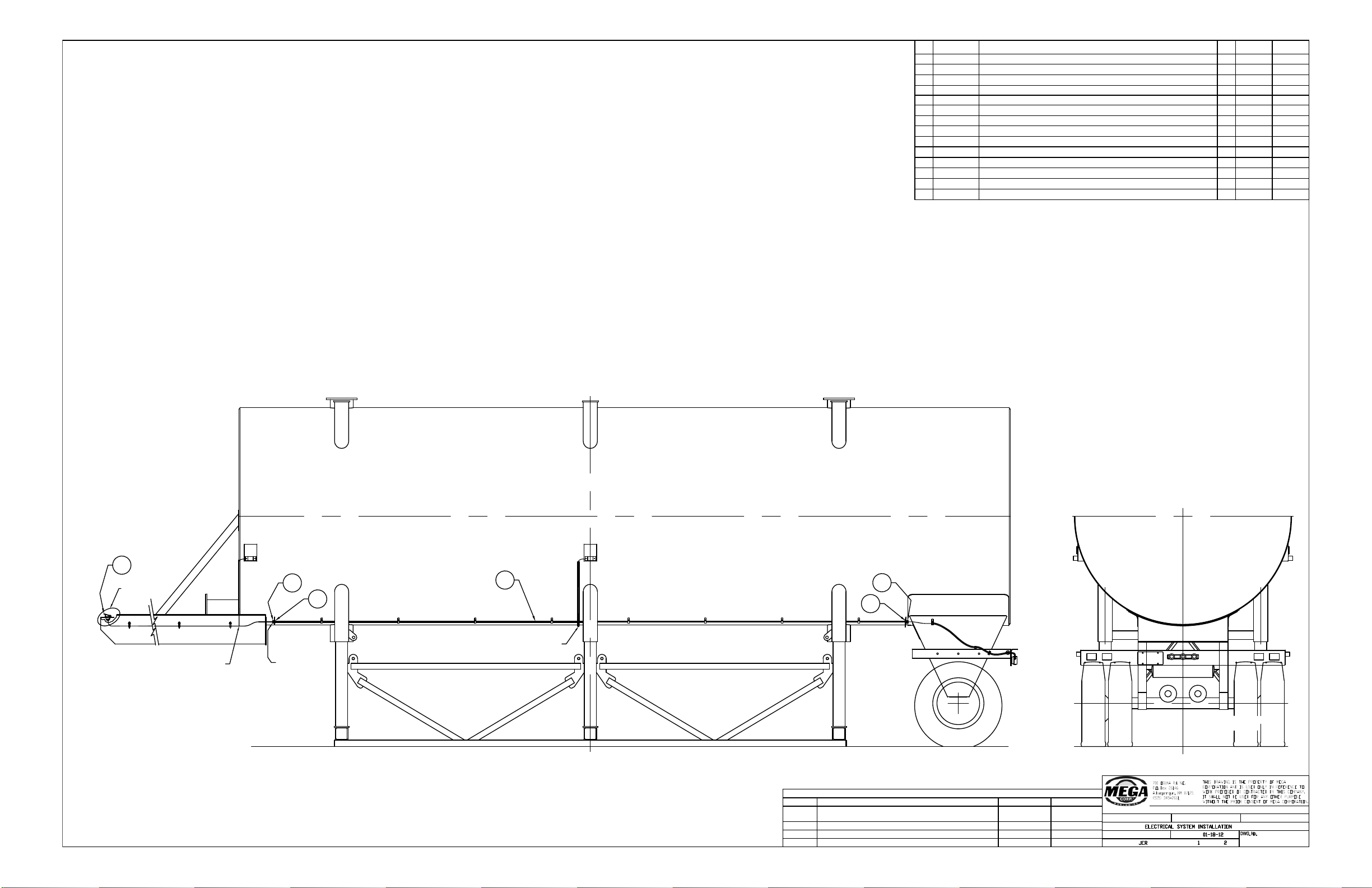
ITEM PART NO. PART NAME
QTY
REF WT
1 300345
FEMALE PLUG ASSEMBLY
1
STK
2 300484
WIRE RED/BLK, 14 GA 2 CONDUCTOR SPLY
3 301794
RUBBER BOOT, SOCKET ELECTRIC
1
STK
4 306373
WIRE TERMINAL, BUTT CONN. SHRINK SLEEVE 16−14GA
8 306373
SPLY
5 306960
WIRE TERMINAL, BUTT CONN. SHRINK SLEEVE 16−14 TO 12−10GA
4 306373
SPLY
6 351141
Ø3/8 NYLON HOSE (SYN FLEX), 40’
1
STK
7 354677
STRAIN RELIEF, ELEC, ALUMINUM, CORD SIZE .312 − .5625
2
STK
8 355022
LOCK RING NUT 1/2" FOR STRAIN RELIEF FITTING
2
STK
9 305434
GROMMET .75ID, 1.63 OD, GROOVE .25 X 1.25Ø
2
STK
10 307073
GROMMET .75ID, 1.63 OD, GROOVE .38 X 1.13Ø
1
STK
11 045811−01
CABLE, 6 CON, 14 AWG X 45’
1 300488
SPLY
12 305161
DEUTSCH PLUG, 6 CON
1
STK
13 305163
LOCK, 6 SOCKET
1
SPLY
14 303380
DEUTSCH PIN, 16−20 AWG
6
SPLY
SHEET OF DRAWN BY:
2 PLACES ± 0.03
TOLERANCE: UNLESS OTHERWISE SPECIFIED
3 PLACES ± 0.010
DRAWING TITLE:
SCALE:
DATE:
ANGULAR ± 1°
NONE
045811
M
REV
DESCRIPTION
DATE
ECR
A
ADDED 306373, 306960, 354677, & 355022 REMOVED
354647, 354648, 350000, 304737K, & 032576
Oct−24−14 CJD
B ADDED 305434, AND 307073 Nov−20−14
CJD
C REMOVED 300486 AND 300488
Jan−29−15
CJD
D ADDED −01, 305161, 305163, 303380 Mar−24−17
DSD
DETAIL 1
SHEET 2
1
6
7
7
8
8
SPLICE FOR
CLEARANCE LIGHTS
SPLICE FOR CLEARANCE LIGHTS
BOTH ENDS OF
ELECTRICAL
CONDUIT
Appendix A
MPT12
A - 22
Page 62
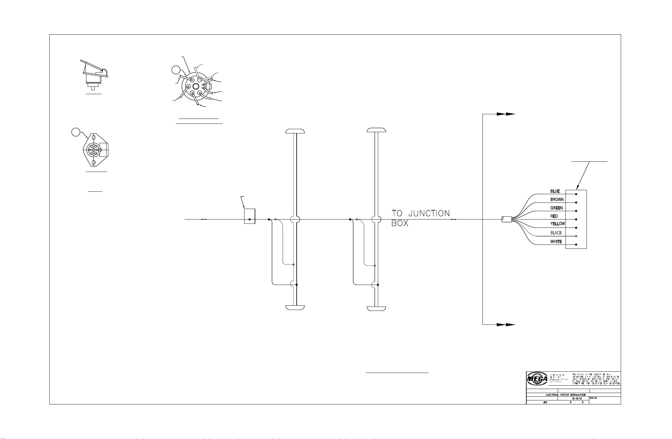
1
3
1WHT
2
B
L
K
3
Y
E
L
4
RE
D
5
G
R
N
6
B
R
N
7
B
L
U
SIDE VIEW
BOTTOM VIEW
FEMALE CONNECTOR
300345
8X SCALE
ENLARGED BOTTOM VIEW
OF CONNECTOR WITH WIRING
NOT TO SCALE
DETAIL 1
SHEET OF DRAWN BY:
2 PLACES ± 0.03
TOLERANCE: UN LESS OTHERWISE SPECIFIED
3 PLACES ± 0.010
DRAWING TITLE:
SCALE:
DATE:
ANGULAR ± 1°
NONE
045811−2
BROWN
GREEN
RED
YELLOW
BLACK
BLACK
2 STR’
WHITE
2 STR’
WHITE
RUBBER BOOT ON
BOTTOM OF
CONNECTOR
FRONT MTG.
PLATE
FROM TRUCK SUPPLY
WIRING DIAGRAM
RED
BLACK
RED
JUNCTION
BOX
LEFT
MIDDLE
CLEARANCE
LEFT
FRONT
CLEARANCE
BLACK
RIGHT
MIDDLE
CLEARANCE
RIGHT
FRONT
CLEARANCE
ITEMS IN
THIS
PORTION
ARE IN
046839
Appendix A
MPT12
A - 23
Page 63
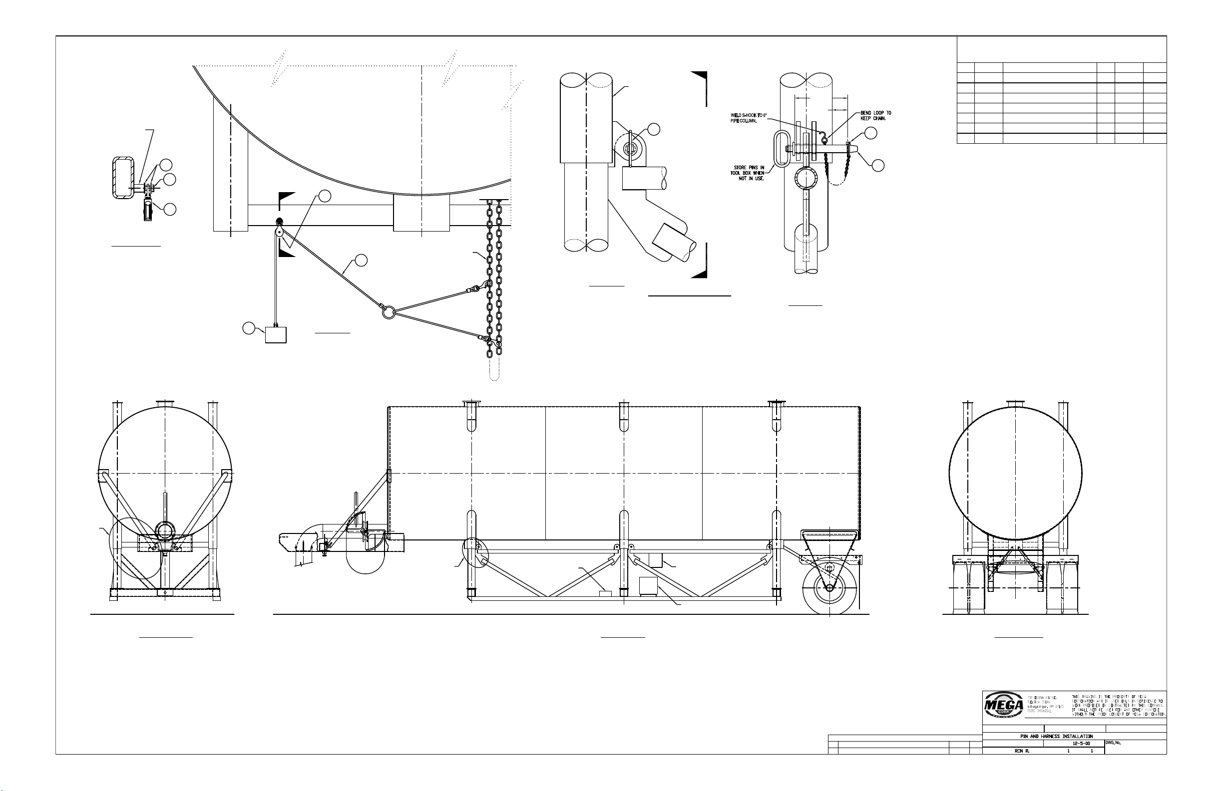
REV DESCRIPTION
REVISIONS
DATE ECR
A (MPT10 & MP T12 ME) ECR 006 RLR 07−09−01 006
Part No.
3
6
7
5
4
2
1
Wt.
BILL OF MATERIAL
Description Qty. Ref. No.
034810
COUNTERBALANCE WELDMENT
1STK
ITEM
HITCH PIN
6
LYNCH PIN W/CHAIN
4
SWIVEL PULLEY
1
354255
354257
354276
350147
C.S. 3/8−16 X 1.50 GR 8
1 350 141
FLAT WASHER 3/8
2 350 000
SASH CORD ASSEMBLY
1
350003
032826
STK
STK
STK
STK
STK
STK
DETAIL 2
6X SCALE
6X SCALE
VIEW BB
B
B
2
2
3
6" PIPE COLUMN
4X SCALE
DETAIL 1
A
A
SECTION AA
8X SCALE
6
5
4
1
4
CHAIN FOR OPERATING
THE BUTTERFLY VALVE
7
ROUND BOSS SEE
DWG 046842
FOR INSTALLATION
DETAIL 1
TOOL BOX
6−1/2 HP
ENGINE
HYDRAULIC
CONTROL
VALVE
DETAIL 2
FRONT VIEW SIDE VIEW REAR VIEW
(5.06)
(1.50)
ASSEMBLY INSTRUCTIONS
ATTACH CHAIN FROM ITEM 354257 TO
S−HOOK. WELD S−HOOK TO 6" PIPE
APPROXIMATELY AS SHOWN.
SHEET OF DRAWN BY:
2 PLACES ± 0.03
TOLERANCE: UNLESS OTHERWISE SPECIFIED
3 PLACES ± 0.010
DRAWING TITLE:
SCALE:
DATE:
ANGULAR ± 1°
NONE
034227
Appendix A
MPT12
A - 24
Page 64
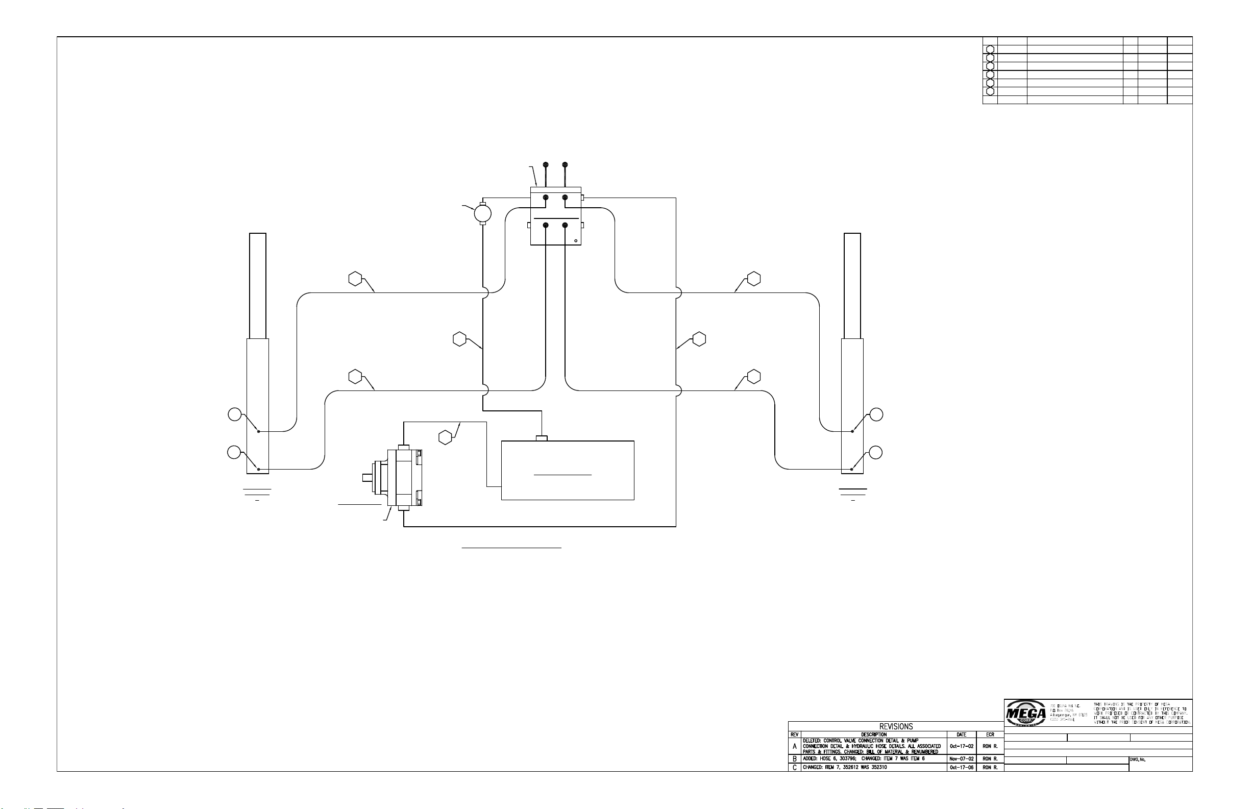
HYDRAULIC RESERVIOR
HYDRAULIC PUMP
HYDRAULIC VALVE
CYLINDER
HYDRAULIC
A
HYDRAULIC
CYLINDER
B
7
SEE DWG.
FILTER
1
4
3
5
5
2
6
034813
034813
034813
034813
034813
1/2" I.D. HOSE ASSY X 121.88"
1/2" I.D. HOSE ASSY X 34.92"
3/4" I.D. HOSE ASSY X 33.30"
3/4" I.D. HOSE ASSY X 41.30"
1/2" I.D. HOSE ASSY X 180.88"
303756
303757
303753
303755
303754
1
2
1
1
1
STK
STK
STK
STK
STK
1
2
3
4
5
352612
AERO−202702−8−8S
4 352296 STK
7
7
7
7
036881
032035
SEE DWG.
HYDRAULIC SYSTEM SCHEMATIC
034813
1/2" I.D. HOSE ASSY X 118.92"
303796
6
1
STK
034813
11
RON R.
Jul−12−01
HYDRAULIC SYSTEM
STAND TANK MPT10 & MPT12 ME
SHEET OF DRAWN BY:
2 PLACES ± 0.03
TOLERANCE: UNLESS OTHERWISE SPECIFIED
3 PLACES ± 0.010
DRAWING TITLE:
SCALE:
DATE:
ANGULAR ± 1°
NTS
NAME OF JOB:
REFPART NAMEPART NO. QTY WTITEM
Appendix A
MPT12
A - 25
Page 65
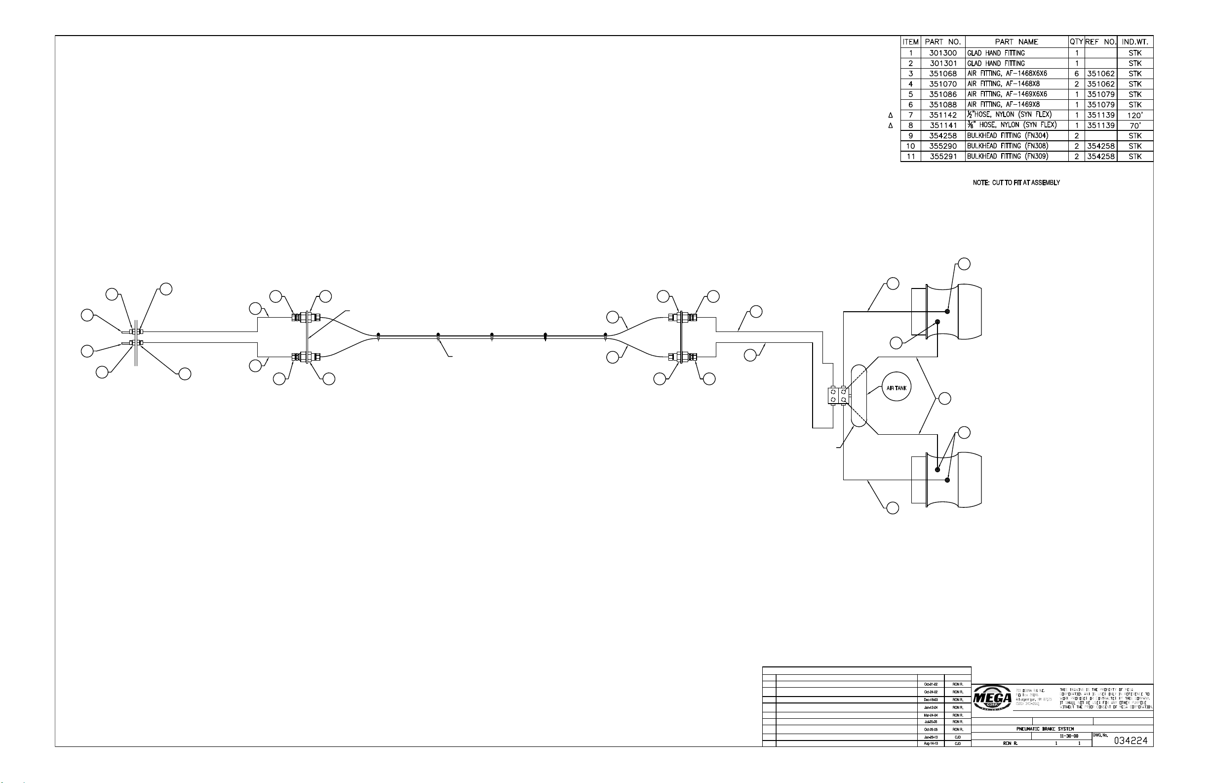
SUPPLY
SERVICE
S
E
L.H. BRAKE
R.H. BRAKE
6
5
3
1
9
9
8
E
S
3
3
8
8
CON
2
7
8
7
8
AIR TANK ASSEMBLY
SEE DWG 034214 REF
7
7
10
4
MANIFOLD PLATE
SUPPORT CLAMP
3 11 11 3
10
4
036655
SHEET OF DRAWN BY:
2 PLACES ± 0.03
TOLERANCE: UNLESS OTHERWISE SPECIFIED
3 PLACES ± 0.010
DRAWING TITLE:
SCALE:
DATE:
ANGULAR ± 1°
NONE
∆
REVISIONS
REV
DESCRIPTION
DATE
ECR
A
ADDED SUPPLY AND RETURN PIPING DETAILS.
B
CHANGED SCHEMATIC & RENUMBERED BOM. DELETED 302534, 350851, 351086,
351082, 300295, & 352474.
C
ADDED 036655.
D
ADDED 351086. CHANGED QTY OF ITEM 1. REPLACED 351088 WITH 351087.
E
CONVERTED PNEUMATIC PIPIN G TO ASSEMBLIES ON BOLT−ON DRW.
F
SEE ECR ST−150.
G
CHANGED SCHEMATIC & BOM. DELETED 351072, 351066, & 352871. RENUMBERED
BOM.
H
REMOVED 03 6655.
I
RENUMBERED BOM.
Appendix A
MPT12
A - 26
Page 66
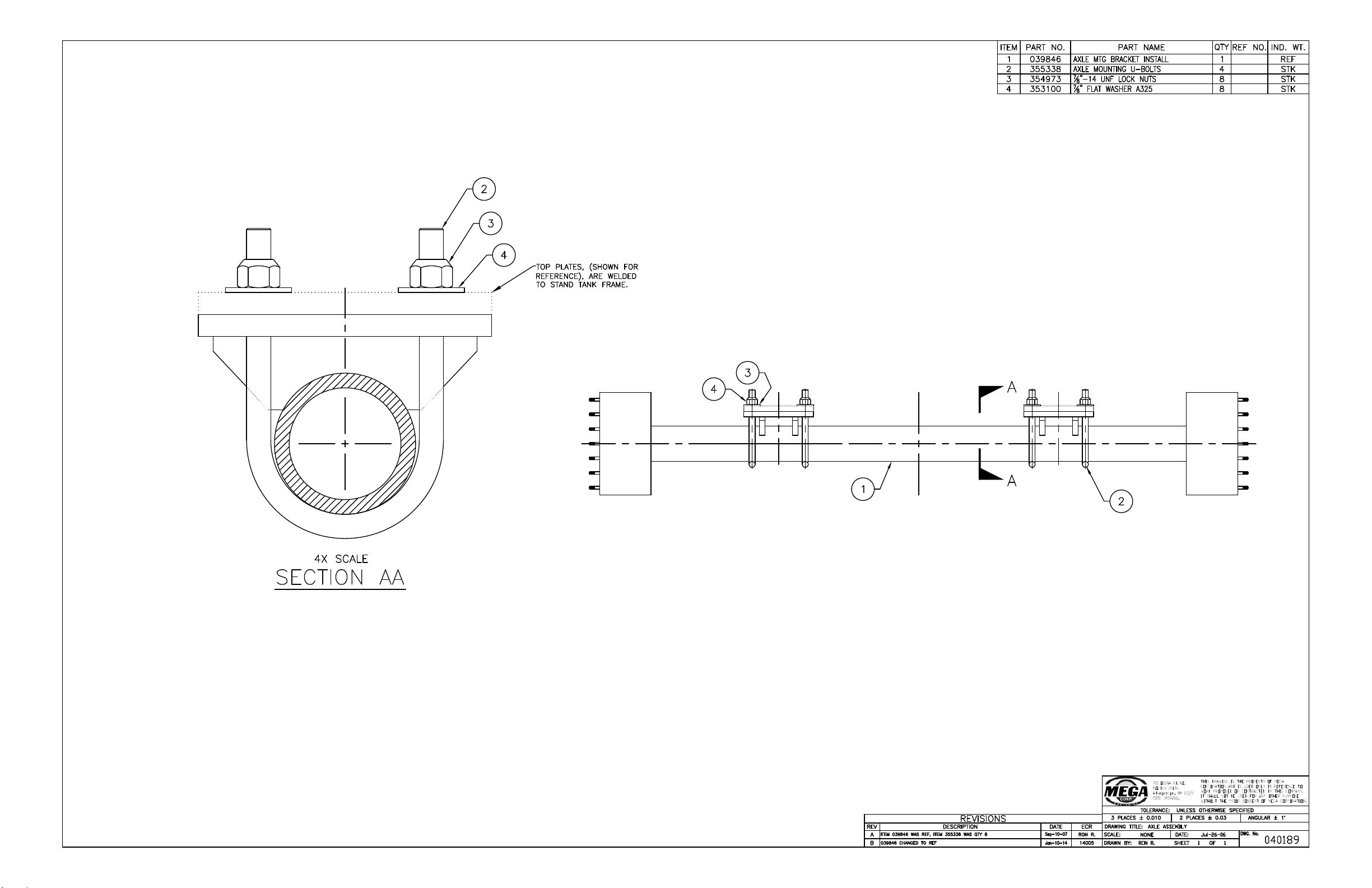
Appendix A
MPT12
A - 27
Page 67
ITEM PART NO. PART NAME QTY REF NO. IND. WT.
1 303230 MEGA ID PLATE 1 STK
700 Osuna Rd. N.E.
P.O. Box 26146
Albuquerque, NM 87125
(505) 345-2661
THIS DRAWING IS THE PROPERTY OF MEGA
CORPORATION AND IS USED ONLY IN REFERENCE TO
WORK PROPOSED OR CONTRACTED BY THIS COMPANY.
IT SHALL NOT BE USED FOR ANY OTHER PURPOSE
WITHOUT THE PRIOR CONSENT OF MEGA CORPORATION.
TOLERANCE: UNLESS OTHERWISE SPECIFIED
3 PLACES ± 0.010 2 PLACES ± 0.030 ANGULAR ± 1°
DWG. TITLE: INSTRUCTION, ID TAG STAMPING
SCALE: NTS DATE: Nov-20-17
DWG. NO.
048512
DRAWN BY: TCS SHEET 1 OF 1
SERIAL NUMBER:
WWWWW
WWWWW IS WORKORDER NUMBER FOR SPECIFIC JOB
MODEL NUMBER:
MPT##
## IS VOLUME OF TANK (AS SPECIFIED ON THE SALES ORDER) DIVIDED BY 1,000 ROUND DOWN TO NEAREST THOUSAND
PART NO.:
MEGA STAND TANK
DATA:
##,### GAL
##,### IS VOLUME OF THE TANK (AS SPECIFIED ON THE SALES ORDER
IN GALLONS ROUNDED DOWN TO THE NEAREST THOUSAND FOR TANKS LARGER THAN OR AT 10,000 GALLONS
OR
IN GALLONS ROUNDED DOWN TO THE NEAREST HUNDERED FOR TANKS SMALLER THAN 10,000 GALLONS
xxxxx
MPT12
12000 GAL
MEGA STAND TANK
Appendix A
MPT12
A - 28
Page 68
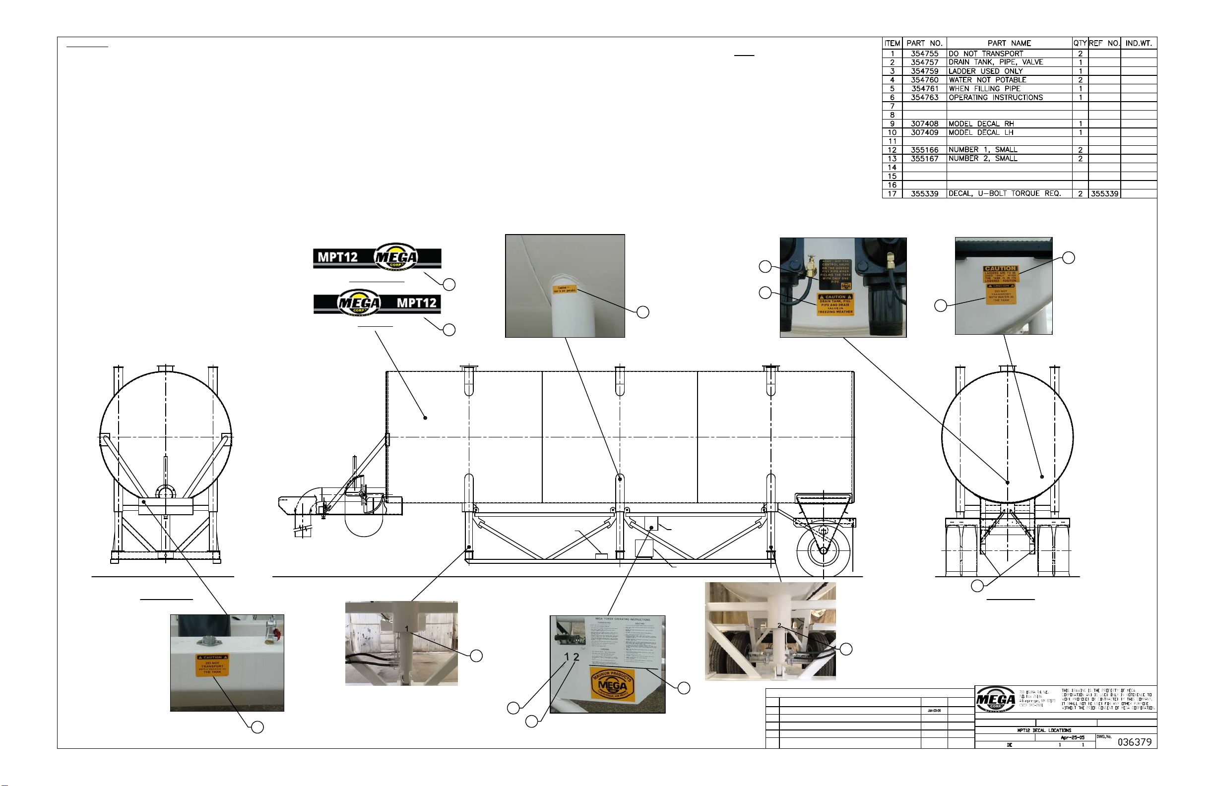
REVISIONS
REV
DESCRIPTION
DATE
ECR
A
ADDED 355339.
RON R.
B 355215 WAS 355073.
Jan−18−12
CSB
C REMOVED 355215
Apr−07−14
CSB
FRONT VIEW
TOOL BOX
6−1/2 HP
ENGINE
VALVE
CONTROL
HYDRAULIC
REAR VIEW
DECAL KIT PART NUMBER 355155
STK
STK
STK
STK
STK
STK
STK
STK
SHEET OF DRAWN BY:
2 PLACES ± 0.03
TOLERANCE: UNLESS OTHERWISE SPECIFIED
3 PLACES ± 0.010
DRAWING TITLE:
SCALE:
DATE:
ANGULAR ± 1°
NONE
4
5
2
1
3
17
6
13
12
1
NOTE
∆ FOR TWO FILL PIPE APPLICATION ONLY
∆
SHIPPING DATA
HEIGHT: 13’−9" (IN LOWERED POSITION)
LENGTH: 40’−6"
WIDTH: 8’−6"
WEIGHT: 21,400 LBS
∆
D CHANGE CYLINDER LABELS TO MATCH CONTROLS
Feb−18−15
CSB
12
13
E
DELETED 354764, 355162, 355165, 355168, 355169, 355177
Mar−23−16
16028
ADDED 307408 & 307409
STK
STK
10
9
THIS SIDE
OPPOSITE SIDE
STK
Appendix A
MPT12
A - 29
 Loading...