

Page 1
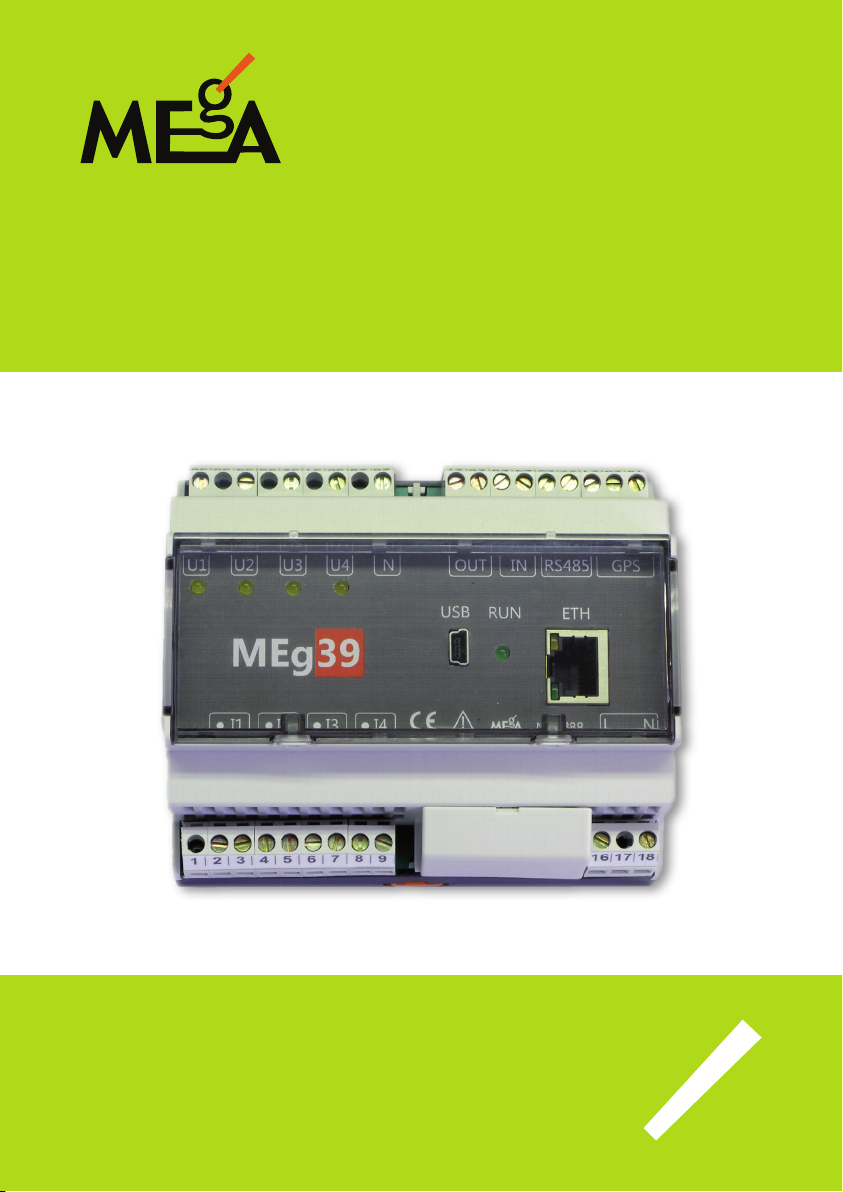
PQ monitor MEg39
User manual
Měřící Energetické Aparáty, a.s.
664 31 Česká 390
Czech Republic
Page 2

Page 3

PQ monitor MEg39 – user manual
PQ monitor MEg39
INTRODUCTION
PQ monitor MEg39 measures four voltage and four current values at LV, MV, HV levels.
It provides the functions of recording, electricity meter and analysis of voltage quality, all
performed simultaneously. In the recording function, PQ monitor MEg39, hereinafter
referred to as the monitor, processes all measured values, evaluates powers, energy and
harmonics up to the order of 64. In the function of class A voltage quality analyser, the
monitor evaluates all parameters for measured three voltages and three currents, as stipulated by the standard. It analyses harmonics and centered subgroups of interharmonics
up to the order of 125. When recording events, the monitor, aside from recording the
course of U
and current. e monitor can operate as an oscillograph with the function of recording
the voltage values U1 to U4 and current values I1 to I4 into data memory; an oscillographic record can be triggered by voltage U4.
RMS1/2
and I
, makes an oscillographic record of all four values of voltage
RMS1/2
e voltage measuring inputs are designed for indirect voltage measurements by means
of instrument transformers for the MV and HV levels and for direct measurements at
the LV level. e current inputs are only designed for indirect measurements by means of
instrument current transformers.
e monitor is supplied by power mains voltage or by DC voltage and it is resistant against short-term power outages. e device can be powered by DC 12 V from a separate
UPS supply MEg101.3. is power supply is connected through the HBUS connector
located in the DIN rail on which the device is installed. is bus connector enables connecting a communication unit MEg202.3, which enables remote transmission of data
from the device by means of GPRS data service using the GSM mobile network. e
monitor is equipped with four communication interfaces. e serial USB interface is
designed for local parameterization of the device and for downloading of measured data,
the Ethernet and RS485 interfaces are designed for connecting to local technological
networks and the RS232 interface is reserved for service purposes.
3
Page 4

Měřící Energetické Aparáty
INFORMATION ON SW
PQ monitor MEg39 package includes a CD with user programs. Parameterization of
measurements, reading of measured data, displaying of direct measurements, including
an oscillographic recording, are carried out by the SW PQ program. Unied program
Data Viewer ensures displaying of measured data in graphic and tabular form of a data
le, export of measured data and printing tasks. Functions of the mentioned programs
are described in separate user manuals [1], [2]. e database based program WebDatOr,
supplied separately, is ready to take care of work with data les from one or more measurement instruments, even of dierent types [3].
BASIC INFORMATION ON MONITOR MEg39
PQ monitor MEg39, Fig.1, is designed for xed mounting in LV, MV and HV networks.
e MEg39 unit is installed in a polycarbonate self-extinguishing box with the dimensions of 108 × 90 × 63 mm with the design for DIN rail mounting. e monitor is installed
under the switchgear box cover with a possibility of sealing to restrict access to the terminals. e instrument panel can be sealed, too. Input terminals of measured voltages and
currents, power supply and communication lines are realized by means of screw terminals for a wire diameter of up to 4 mm
2
. Measured voltages are led to the corresponding
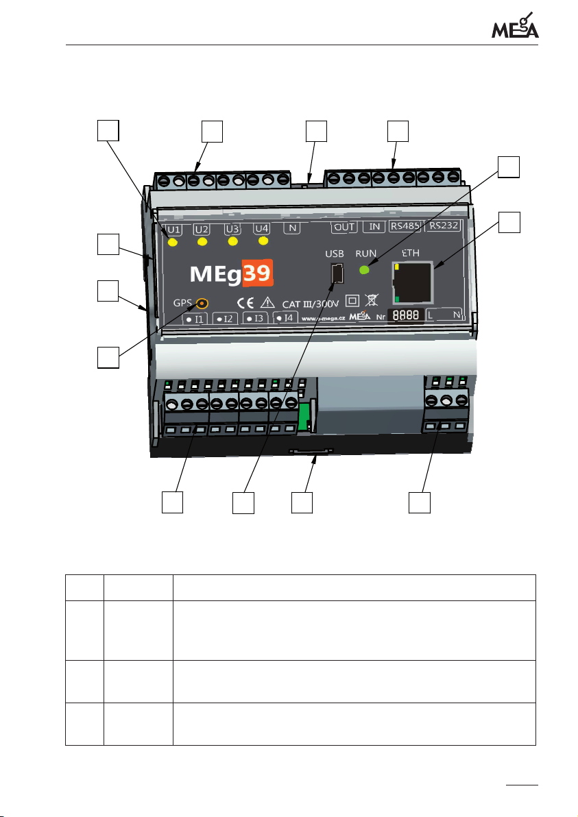
terminals U1 (36), U2 (34), U3 (32), U4 (30) and N (28). e four yellow LEDs U1, U2,
U3 and U4 signalize by permanent light the presence of input voltages within preset
tolerances. If a measured voltage is beyond preset tolerances, the corresponding LED
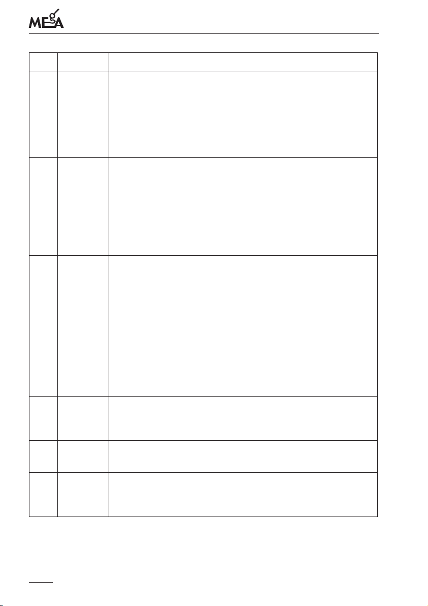
ashes shortly, see the description of LED voltage indicators in Table 1. e unit panel
also contains a green LED indicator RUN, signalizing the operation of the MEg39 unit.
Measured currents are led to the pairs of terminals I1 (2,3), I2 (4,5) and I3 (6,7), I4 (8,9)
whilst the current input terminal is marked by a dot.
Supply voltage is connected to the terminals L (16) and N (18).
Two-value input signal is led to the IN (24,25) terminals, the 25 terminal is positive. e
output signal OUT (26,27) is realized by means of the relay contact.
e miniUSB connector located on the panel of the unit is designed for local communication. Remote communication is realized by means of the RS485 interfaces at the
terminals 22 and 23. Furthermore, it is possible to use the Ethernet interface, whose RJ45
connector is located at the panel of the unit and it enables using the functions provided
by the built-in webserver.
4
Page 5
PQ monitor MEg39 – user manual
Fig. 1 – Designation of elements of PQ monitor MEg39 – description in Table 1
6
12
11
7
1 2 3 4
2
1
8 10
5
4
17 18
8 9
7
5
6
3
8 9
16
Tab. 1: Description of device components
Item Name Description
1
Voltage
inputs
Terminals for connecting signals of the secondary windings of
instrument voltage transformers for the MV and HV levels or for
direct connecting of phase voltages at the LV level.
2
3
Current
inputs
miniUSB
Terminals for connecting signals of the secondary windings of
instrument current transformers. e input is marked with adot.
USB 2.0 interface connector for local communication
connector
5
Page 6
Item Name Description
Měřící Energetické Aparáty
4
5
6
RJ45
connector
Status
of LED
indicator
RUN
Status of
measured
voltages
U1, U2,
U3, U4
ETHERNET 100BaseTx interface connector for connecting in
local network.
• e green LINK_LED signalizes data line speed
(lit 100 Mbit/s / not lit 10 Mbit/s)
• e orange ACTIVITY_LED light signalizes a data transmission in progress
Short ashing – the monitor is performing measurements according to the programmed parameterization.
Repeated short ashing – the monitor has been programmed but
is not measuring yet, because the preset time of measurement
start has not come yet or the supply has not switched on due to
programmed measurement with delayed start.
Alternating light 1:1 – oscillographic recording.
Signalization of the status of voltage at the inputs U1, U2, U3
and U4 during measurement at the LV level (Y-connection) or
U1-U2, U2-U3, U3-U1 during measurement at the MV and HV
level (delta connection).
Light:
• constant – voltage is within the preset tolerance range
to 1.1 Un)
(0.9 U
n
• one ash – voltage is within the preset range of interruption
• two ashes – voltage is within the preset range of dip
• three ashes – voltage is the preset range of swell.
7
8
9
6
GPS
antenna
connector
DIN rail
lock
Power
supply
terminals
Connector for connecting a coaxial cable of antenna for receiving
GPS time synchronization signal.
Orange locks situated at the top and bottom of the device must
be unlocked for dismantling the device from the DIN rail.
Terminals for connecting power supply voltage
Page 7
PQ monitor MEg39 – user manual
Item Name Description
Input and
10
output
signal
terminals
HBUS bus
11
connector
Rating
12
plate
SAFETY INFORMATION
• is information must be read very carefully.
• Warnings warn of issues representing safety risks to operating personnel.
• Cautions state conditions and issues that could result in damage to the monitor.
Warning
• Attention! Operating personnel performing installation of the device into circuits with live parts must be equipped with and use during installation personal protective means and other safety equipment.
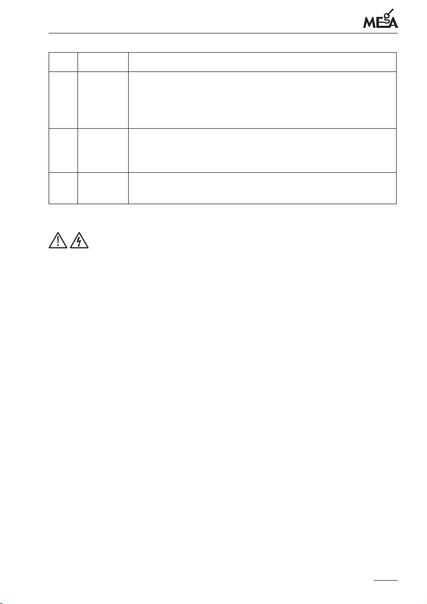
Terminals for connecting two-state signals and data interfaces
RS485 and RS232.
Bus connector for interconnecting with UPS supply MEg101.3
and communication unit MEg202.3
(HBUS is installed between the device base and DIN rail)
e rating plate contains data valid for the specic version of the
monitor
• Any use of PQ monitor MEg39 in a way for which it has not been des igned
by the ma nufacturer can impair the protection provided by the PQ monitor
MEg39.
• Personnel performing installation of the device must be qualied for work under and
near hazardous voltage. ey must also be trained in providing rst aid.
• e monitor can only be operated by qualied personnel.
• Maintenance and repairs of the monitors can only be carried out by the manufacturer or service organizations trained by the manufacturer.
• It is not permitted to use any other accessories than those included in supply of
amonitor.
7
Page 8
Měřící Energetické Aparáty
Caution
e meaning of symbols used in the user manual and in descriptions of the PQ monitor
MEg39:
Note in documentation / Warning, risk of danger
Warning, electric shock hazard
CAT III
Overvoltage category, characterizing the state of temporary overvoltage.
Usually for LV installations in buildings, behind electric energy meter
fuses
Safety class II, double or reinforced insulation
IP code
Degree of protection by cover
Product is designated for recycling and waste-collecting facilities
Declaration of compliance – European Community
e maximum voltage to the common conductor can be 300 VAC otherwise
there is a risk of damage to the monitor
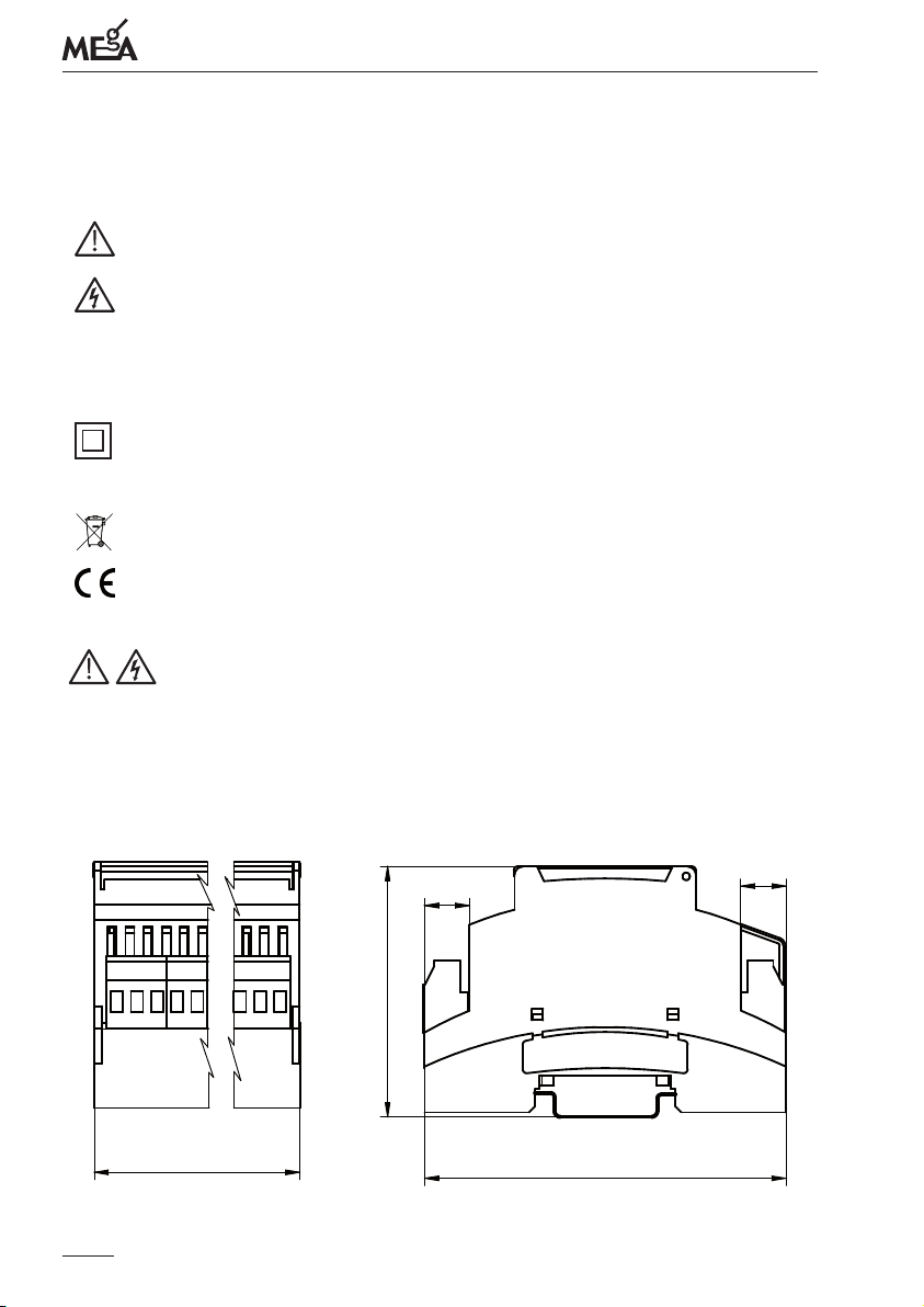
Fig. 2: Dimensions of the device
11,2
11,2
62,2
108
89,7
8
Page 9
PQ monitor MEg39 – user manual
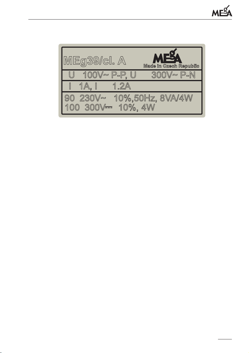
Fig. 3: Design of rating plate for measurements at the MV and HV voltage level
MEg39/cl. A
U
100V~ P-P, U 300V~ P-N
n
I
1A, I 1.2A
n
÷
9
0 230V~ 10%,50Hz, 8VA/4W
1
00 300V 10%, 4W
Explanat ion to the rating plate
e rating plate of the monitor, see Fig. 3, is located on the left side of the cover. In addition to manufacturer‘s identication data and monitor designation, it includes specication
of power supply voltage range and consumption for the stated power supply voltages.
Voltage inputs:
Measurement at the MV and HV levels are delta U1-U2, U2-U3 and U3-U1 with the
rated value of 100 V, voltage U4 is measured against the N input with the rated voltage
of 100 / √3 V.
e maximum voltage value at the inputs U1, U2, U3 and U4 against N is 300 VAC.
Connected to the current inputs I1, I2, I3 and I4 are the secondary windings of instrument current transformers with the rated current of 1 A.
e measuring range of the current inputs is up to 1.2 In.
max
+
-
÷
+
-
Made in Czech Republic
max
MEASURING CONNECTION WITH INSTRUMENT MEASURING
TRANSFORMERS IN A MEASURING CHAIN
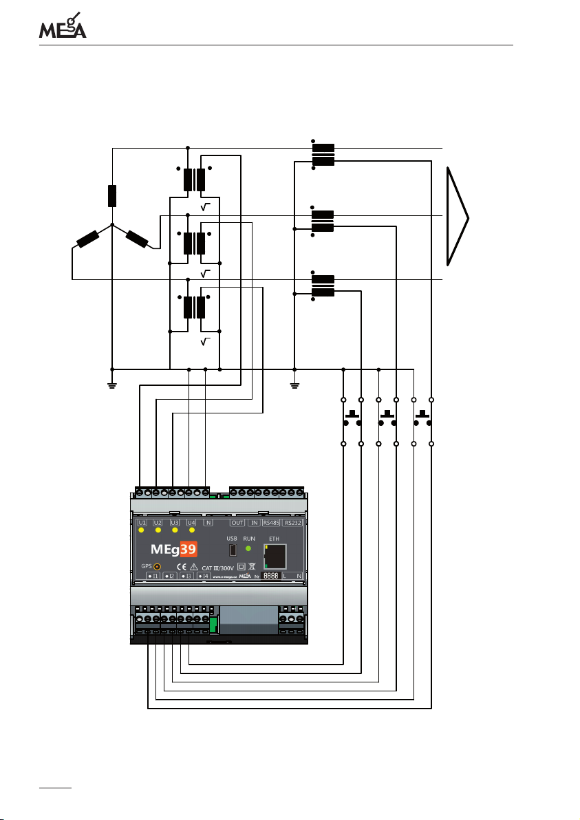
In MV and HV networks, measurements are indirect via measuring instrument transformers.
For three-phase voltage measurement it is necessary to connect voltages U1, U2 and U3
in the left rotation direction, at which the device is calibrated.
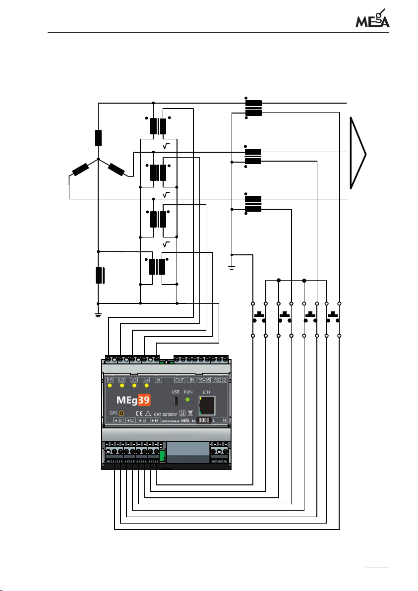
When measuring is performed at the MV level and the voltage input U4 is not used, it is
recommended to connect this input with the N input.
9
Page 10
Měřící Energetické Aparáty
Fig. 4: ree-phase measuring of line to line voltages and phase currents in MV and
HV voltage with earthed center
L1
L2
(U/100/ )V
3
U1
I1
L3
(U/100/ )V
3
U2
U3
I2
Positive
I3
direction
of energy
flow
(U/100/ )V
3
36
19
10
1
18
Page 11
PQ monitor MEg39 – user manual
Fig. 5: Measurement of line to line voltages, U0 voltage, phase currents, I0 current
in a compensated MV network
L1
TL
L2
L3
(U/100/ )V
3
(U/100/ )V
3
U1
U2
U3
I1
I2
Positive
direction
I3
of energy
flow
(U/100/ )V
3
U4
(U/100/3)V
36
19
1
18
11
Page 12
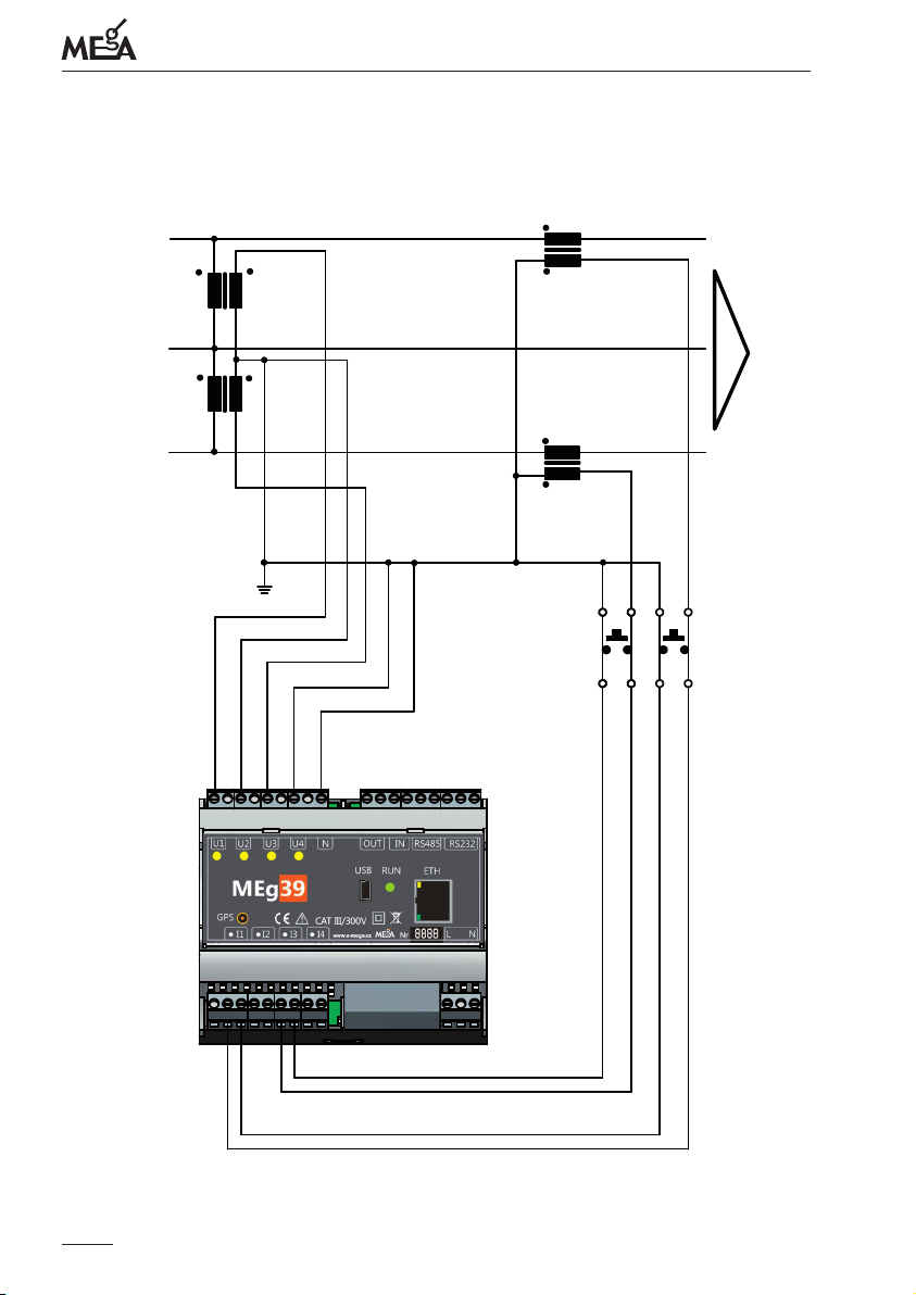
Měřící Energetické Aparáty
Fig. 6: Measurement of line to line voltages and phase currents in the Aron connection
at the MV network
L1
U1
L2
U2
I1
L3
Positive
U3
36
1
19
18
I3
direction
of energy
flow
12
Page 13
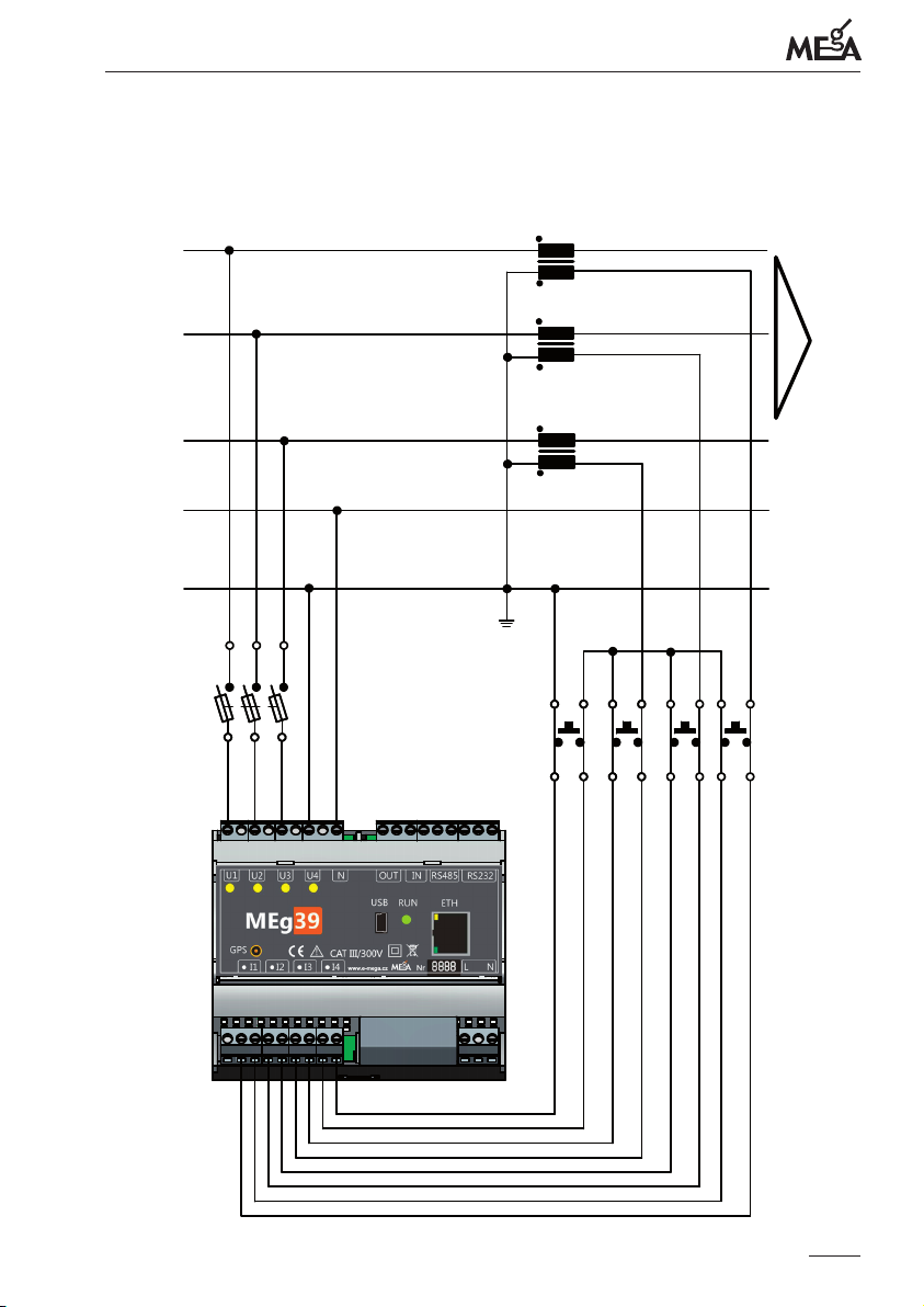
PQ monitor MEg39 – user manual
Fig. 7: Measurement of phase voltages, voltage between neutral conductor and ground
and phase currents including phase currents dierence
L1
I1
L2
I2
L3
N
PE
Positive
I3
36
19
direction
of energy
flow
1
18
13
Page 14
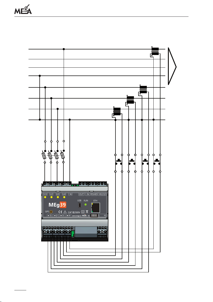
Měřící Energetické Aparáty
Fig. 8: ree-phase measurement of voltage and current at the LV output and measure-
ment of phase voltage and current of another LV output
L1
L2
L3
PEN
L1
L2
L3
PEN
Positive
direction
of energy
flow
36
19
14
1
18
Page 15
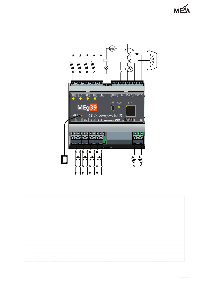
PQ monitor MEg39 – user manual
Fig. 9: Connection of device terminals
36
1
GPS
antenna
U3
U1
U2
I1 I2 I3 I4
max 30V 1A
U4
~
N
RS485
A
B
80230VAC, 50Hz
90300VDC
RS232
5
1
19
18
250V/2A
Tab. 2: Description of the function of MEg39 terminals
Terminal number Function
1 2 I1 current input
3 I1 current output
4 I2 current input
5 I2 current output
6 I3 current input
7 I3 current output
15
Page 16
Terminal number Function
8 I4 current input
9 I4 current output
10 11 12 13 14 15 16 L (power supply)
17 18 N (power supply)
19 RS232 GND
20 RS232 Tx (DTE)
21 RS232 Rx (DTE)
22 RS485 B (negative idle level of signal)
23 RS485 A (positive idle level of signal)
24 IN_GND
25 IN+
26 OUT
27 OUT
28 N
29 30 U4
31 32 U3
33 34 U2
35 36 U1
Měřící Energetické Aparáty
16
Page 17

PQ monitor MEg39 – user manual
MEASURED DATA
e range of measured data depends on connection for measurement and measurement
parameterization. Measured data are divided into data of continuous phenomena of voltage quality, event data and recorder data.
Data of continuous phenomena of voltage quality (aggregation interval 10 min):
- Time of evaluation
- Voltage unbalance
- Frequency
- Voltage magnitude
- Voltage deviations U
over
, U
under
- Flicker Pst and Plt
- THDU
- DC component, fundamental harmonic up to 125th harmonic of voltage
- Centered subgroups of interharmonic component of voltage up to the order of 125
- Level of voltage signals
- Flagged data
- Currents
- Basic to 125th harmonics of currents
- Centered subgroups of interharmonic I up to the order of 125
Data at events :
- Time of event
- Event duration
- Moments when the limits for interruption, dip and swell of voltage and current
are exceeded
- Residual and maximum values of voltage and current
- Curves of voltages U
and currents I
RMS1/2
RMS1/2
- Oscillogram of voltage and current curves during event
- Harmonic voltages and currents during event
17
Page 18

Měřící Energetické Aparáty
Recorder data (aggregation interval from 1 s to ¼ h pursuant to measuring parameterization):
- Time of evaluation
- Voltage
- Currents
- Active powers
- Reactive powers
- PF
- THD
U
- THD
I
- Harmonic components of voltages up to the order of 64.
- Harmonic components of currents up to the order of 64.
- Active and reactive energy (6 registers for each phase)
e above stated data of continuous phenomena of voltage quality are stipulated for the
voltages U1, U2, U3 and currents I1, I2, I3.
e above stated recorded data of events starting from an exceeding of the dened limits
for voltages U1 to U4 and for currents I1 to I3 are recorded for all the stated values.
e above stated recorder data apply to voltages U1 to U4 and currents I1 to I4.
18
Page 19
PQ monitor MEg39 – user manual
INSTALLATION OF MONITOR, PREPARATION FOR MEASUREMENT
Connecting of power supply and measuring voltage circuits must be done in volta-
ge-free state.
It is not permitted to connect the voltage inputs to phase voltages higher than 300 VAC
and line to line voltages higher than 520 VAC in CAT III overvoltage category circuits.
Installation of the MEg39 monitor may only be performed by qualied personnel
equipped with personal protective means against electric shock and trained in pro-
viding the rst aid.
Monitor MEg39 is to be installed on DIN rail TC35, while due to reasons of safety
against electric shock and increased resistance against external machanical impacts, requires covering of cover with terminals by cover panel. DIN rail should be preferentially
in horizontal position, labels on device panel are readable from left to right.
On DIN rail can be installed also power supply MEg101.3a or MEg101.3b and
GPRS communication unit type MEg202.3 if needed. Units are inter connected
using HBUS connec tor.
Power supply connecting
MEg39 monitor can be supplied either directly by AC voltage or by DC voltage connected to power supply terminals 16 and 18 or by DC 12 V from the UPS MEg101.3 via
the HBUS. Connected to terminals 16 and 18 can be AC voltage within the range from
90 V to 230 V or DC voltage from 100 V to 300 V, independent on polarity.
1. Terminals 16 and 18 of the monitor MEg39 are connected via the two-pole LV fuse
disconnector with fuses 2 A / 500 V to the terminals L and N of the network and their
connection is made with cables certied for installation in a LV cabinet.
2. After a temporary state with a duration of ca 1 s, when the processor is checking the
function of all circuits, it is necessary to check the LED RUN status according to
apreviously programmed measuring mode, see in Tab. 1.
Connecting of measured voltages
Measured voltage must always be led to the reference voltage input U1.
e monitor MEg39 can be used for single-phase measurements, too.
19
Page 20
Měřící Energetické Aparáty
3. For indirect measurements at the MV and HV level, the measuring voltage inputs are
connected according to the wiring diagrams in Fig. 4 to Fig. 6 to the output terminals
of voltage instrument transformers.
For direct measurements at the LV level, the measuring voltage inputs are connected
to measured voltages at phases L1, L2 and L3 via the three-pole fuse disconnector
with fuses 2 A / 500 V, see in Fig. 7.
When measuring phase voltage of another, non power-connected branch of the LV
network by means of the measuring input U4, it is necessary to insert a one-pole
fuse disconnector with a fuse between the U4 input of the MEg39 monitor and the
measured voltage, see in Fig. 8.
4. When the fuse disconnector is switched „ON“, check the function of the LEDs U1,
U2, U3 and U4, which signalize the status of measured voltage at the corresponding
inputs.
Connecting measured currents
Connecting current circuits must be performed either with the power switched o or
with short-circuited secondary winding of the current instrument transformer.
All current inputs of the monitor MEg39 have the same value of rated current of either
1 A or 5 A, depending on an order.
e type and rated value of primary current of the current instrument transformer is
set by the user according to voltage level and required measured current at the place of
installation.
5. Currents indirectly measured by measuring instrument transformers are connected
via short-circuited current double terminals to the current inputs I1, I2, I3 and I4,
as the case may be, of the monitor MEg39 according to Fig. 4 to Fig. 8. e secondary winding of the current transformer inserted in the L1 phase is connected to
the I1 input, e secondary winding of the current transformer inserted in the L2
phase is connected to the I2 input, e secondary winding of the current transformer
inserted in the L3 phase is connected to the I3 input. Similar procedure is used for
connecting the current input I4, as necessary.
20
Page 21
PQ monitor MEg39 – user manual
To ensure a reliable function of the connection, it is recommended to earth the secondary
circuit of each instrument transformer. Earthing of the secondary circuit is carried out
at one point.
Start of measurements and check of correct wiring
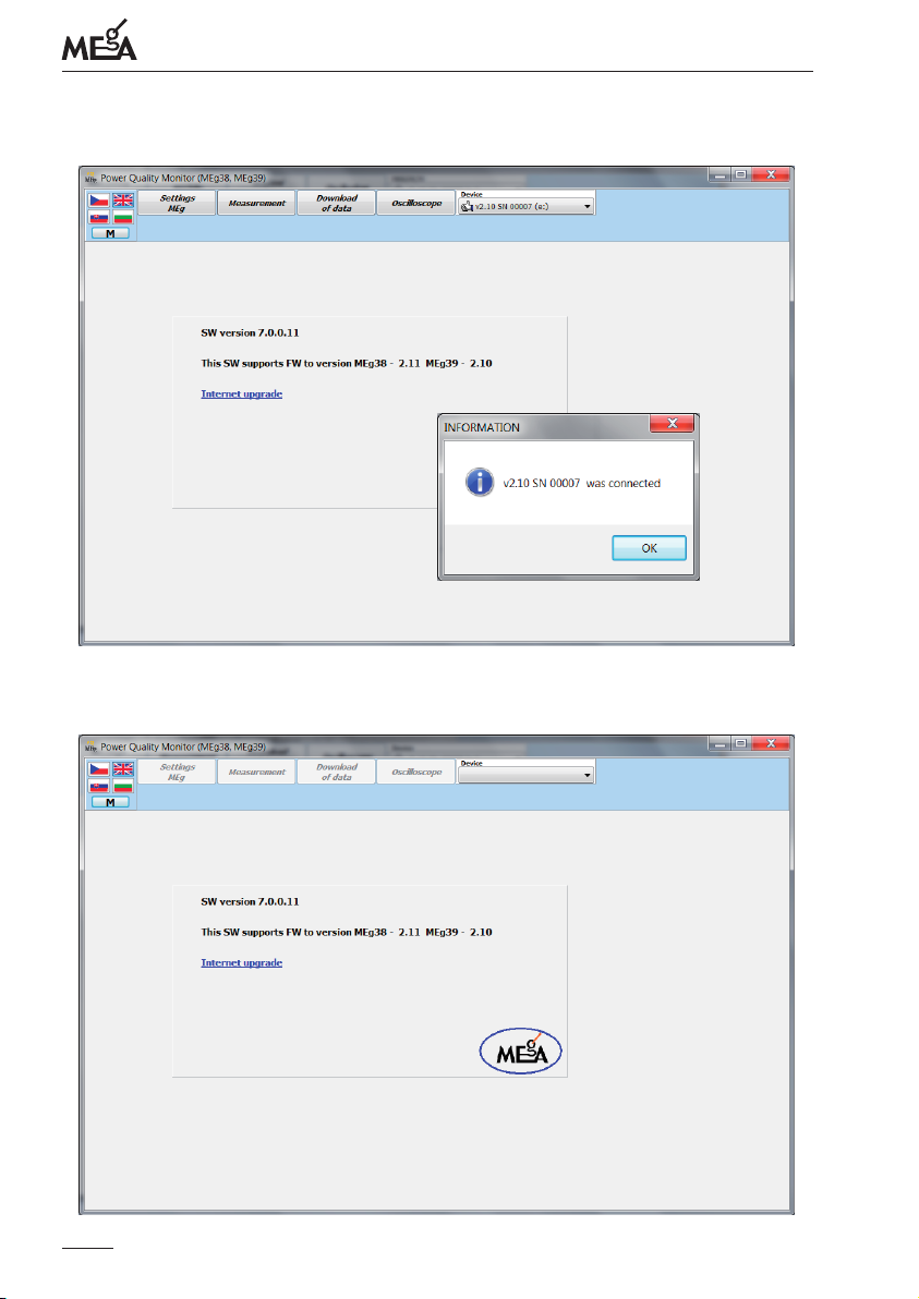
6. Displayed on PC with opened Power Quality Monitor program [1] in the drop-down
menu of connected devices is a pictogram of communication connection with the
monitor, FW version and the monitor serial number. Captions of all buttons in the
window are in bold letters, see in Fig. 10.
If the program Power Quality Monitor is launched and the monitor is disconnected
or connected improperly, PC displays the window with the empty drop-down menu
and the buttons are inactive, see in Fig. 11.
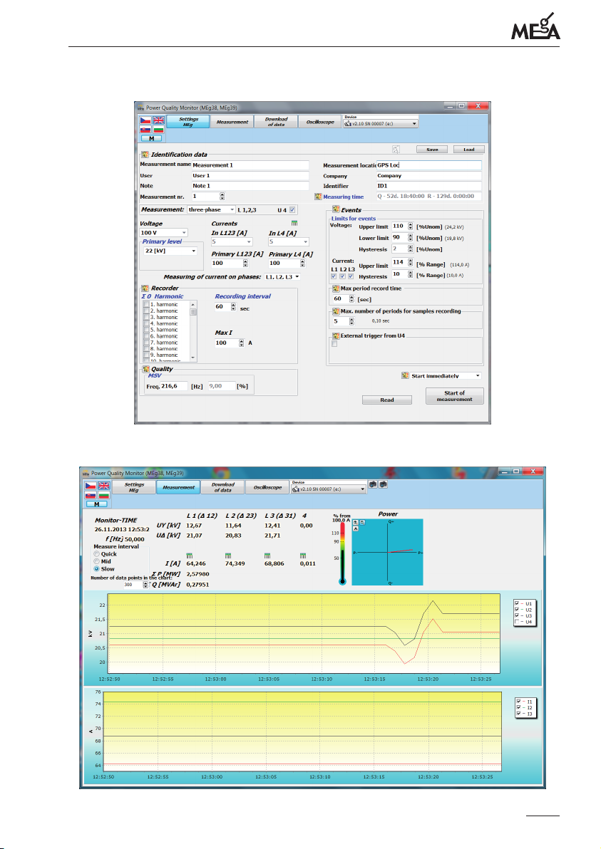
7. Pressing the button Settings MEg displays in the program window the parameterization of measurements, where it is necessary to ll in rst the identication data of
measurement and then, according to measuring connection, to select one-phase or
three-phase measurement, voltage level (in the case of MV/HV), transformer ratio of
the instrument current transformers and other measurement parameters, as the case
may be, see in [1].
An example of measurement parameterization is in Fig. 12
8. Pressing the button Start of measurement deletes all previously measured data stored in the device memory and launches measurements according to the newly selected parameterization. Pressing the button Measurement and selecting the RMS
menu displays the window of measured values, their time courses and the phasor
diagram. An example is in Fig. 13. It is necessary to check the measured values and
the correct direction of installation of the current transformers.
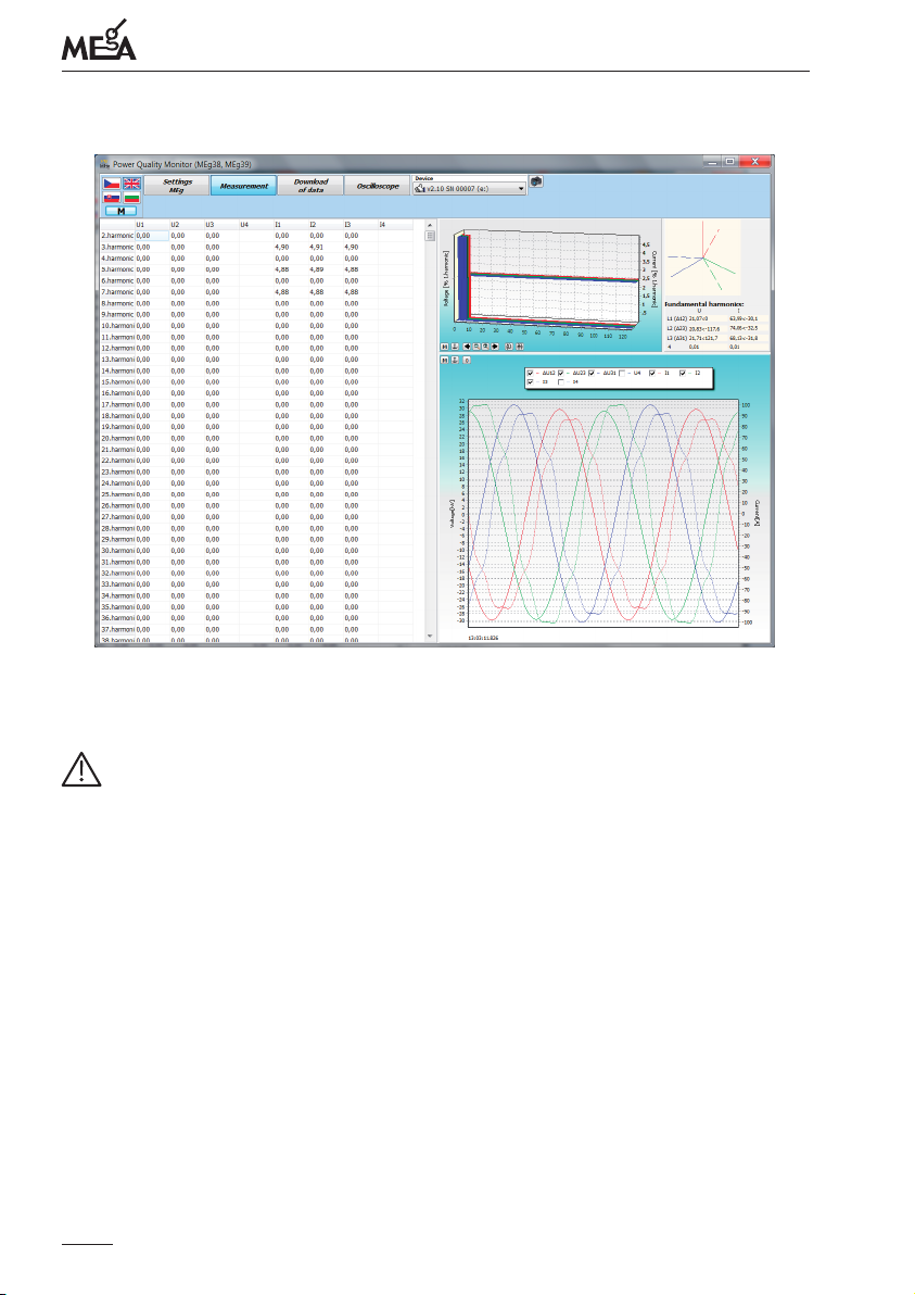
9. Pressing the menu button Measurement and selecting the Samples menu displays
harmonic components of measured voltages and currents, oscillographic curves and
a phasor diagram showing the orientation of current directions to voltage directions.
An example is in Fig. 14.
During measurement of line to line voltage and phase currents at the MV level there is
aphase shift between voltage and current by ca 30°. is does not necessarily apply to
the I4 current..
21
Page 22
Měřící Energetické Aparáty
Fig. 10: e main window of SW PQ when communication with MEg39 has been
established
Fig. 11: e main window of SW PQ when communication with MEg39 has not been
successfully established
22
Page 23
PQ monitor MEg39 – user manual
Fig. 12: An example of settings - measurement parameterization
Fig. 13: Measuring and inspection of connected values, a time course of eective values
23
Page 24
Měřící Energetické Aparáty
Fig. 14: Measurement and inspection of connected values, oscillographic curves and FFT
MAINTENANCE
Caution
• Repairs of the monitory during the valid warranty period may only be performed by
trained and qualied personnel of the manufacturer or service organizations of the
manufacturer.
• e monitor must not be exposed to eects of chemicals
• e monitor may only be transported in the original transport packaging supplied
by the manufacturer
• Re-calibration of PQ monitors MEg39 class A is recommended every two years and
PQ monitors MEg39 class S every three years from the date of purchase or previous
calibration.
When used properly and in accordance with this manual, the monitor does not require
any special maintenance. Only when the device is dirty, it should be cleaned thoroughly
by moist cloth without any cleaning agents.
24
Page 25

PQ monitor MEg39 – user manual
BATTERIES
Used in the monitor are the following batteries:
• lithium battery CR2032 for real time clock circuit,
• supercapacitors with the declared operation life of 10 years.
DISPOSAL
When the monitor is put out of operation, it must be disposed of properly by recycling
in waste collecting facilities according to the regulations for electronic waste handling.
WARRANTY
A warranty period of 24 months from the date of sale is provided for the monitor but no
longer than 30 months after shipping from the manufacturer. Defects occurring during
this warranty period and provably due to defective design, faulty craftsmanship or material defects shall be repaired by the manufacturer or manufacturer‘s service organization
free of charge.
ORDERING
An order must contain quantity of PQ monitors MEg39, class A or S, requiren nominal
voltage level (LV or MV/HV) and required nominal current range (1 A or 5 A).
Optional accessories:
• GPS antenna with 5 m or 10 m cable
• HBUS bus connector for connecting the communication unit and uninterruptible
power supply
• uninterruptible power supply MEg101.3
• communication unit MEg202.3 for remote data transmission by means of the GPRS
service
25
Page 26

Měřící Energetické Aparáty
TECHNICAL PARAMETERS
General information
e stated uncertainties of measurement apply to the reference conditions.
e development and production of the monitor is in accordance with the standard of
ISO 9001.
Reference conditions
Ambient temperature: 23 °C ± 2 K
Relative humidity: 40 % to 60 %
Left-direction voltage system at the inputs U1, U2 and U3.
Supply voltage: 230 V
, 50 Hz
AC
Operating conditions
Operating temperature: -20 °C to +55 °C
Settle time: 10 minutes
Relative humidity: 10 % to 90 %, non-condensing
Storage
Storing temperature: -30 °C to +60 °C
Protection against eects of water and chemicals
Protection against long-term eect of UV-radiation
Desig n data
Dimensions: 110 × 90 × 63 mm
Weight: 0.4 kg
Protection: IP00 according EN 60 529
IP20 when installed into LV switchgear
with cover panel above device terminals
Overvoltage category: CATIII / 300 V according to EN 61010-2-030
Safety class: II, reinforced insulation
26
Page 27
PQ monitor MEg39 – user manual
EMC
EN 61326-1:2006
Electrical equipment for measurement, control and laboratory use – EMC requirements
Part 1: General requirements 31
Voltage on network terminals, electromagnetic interference
EN 55011 ed.3:2010
Industrial, scientic and medical equipment – Radio-frequency disturbance characteristics – Limits and methods of measurement
Emitted high-frequency electromagnetic eld
EN 61000-4-3 ed.3:2006
Electromagnetic compatibility (EMC) – Part 4-3: Testing and measurement techniques
– Radiated, radio-frequency, electromagnetic eld immunity test
Power supply
Supply voltage terminals 16, 18: 90 VAC to 230 VAC ± 10 %, 50 Hz
100 VDC to 300 VDC ±10 %
HBUS supply voltage: 8 VDC to 12 VDC (max 13 VDC) from uninterruptible
power supply MEg101.3
Consumption: 8 VA, 4 W / 230 V
4 W / 300 V
2 W / 12 V
DC
DC
AC
Fuse type: FSK 00.1/500 mA-T,
e fuse is located under the plastic cover located next
to the power terminals 16 and 18.
e fuse can be changed only with the power
supply voltage disconnected at terminals 16 and 18.
Fuse is not connected in the circuit of power supply
voltage 12 V over HBUS connector.
Backup supply without UPS: 3 s with charged supercapacitors, charging time – 5 min
Data memory
Capacity: 512 MB
27
Page 28

Měřící Energetické Aparáty
Measuring characteristics
A/D convertor: 16 bit
Sampling frequency: 256 samples a period
Antialiasing lter: digital lter of the FIR type
Phase lock: controlled by passage of basic harmonic voltage U1 through zero
Aggregation intervals: quality function – pursuant to the standard of EN 61000-4-30, ed. 2
recorder function – from 1 sec to 1/4 hour
Aggregation synchronization: pursuant to the standard of EN 61000-4-30, ed. 2,
Time base: ±1 sec in 24 hours at operating temperature,
when GPS signal not connected
Voltage inputs U1, U2, U3 and U4
SW setting of voltage level: LV MV and HV
Rated phase voltages U
JRated delta voltages UnP-P: 400 VAC 100 V
P-N: 230 VAC 100 / √3 V
n
AC
AC
Measuring range of phase voltages: 300 VAC 190 VAC
Maximum input voltage P-N: 300 V
AC
Uncertainty of voltage measurement
with f = 50 Hz: 0.05 % rdg ± 0.025 % U
n
Frequency range: up to 7.2 kHz
Input resistance: 1.68 MΩ
Temperature coecient: 0.05 % / 10 K
Measurement: direct indirect
Max. voltage transforming ratio: none 999 kV / 100 V (optional SW PQ)
Current inputs
Rated current value I
Current measuring range: 5 % I
: 1 A or 5 A
n
to 120 % In
n
Frequency range: 40 Hz to 7.2 kHz
Current measurement uncertainty
I
= 1 A, 5 A: 0.05 % rdg. ± 0.025 % In (45 Hz to 60 Hz)
n
Temperature coecient: 0.02 % / 10 K
Harmonic measurement uncertainties
I
= 1 A, 5 A: ± 5 % I
n
harm
at I
harm
a ± 0.15 % In at I
28
≥ 3 % In
< 3 % I
harm
n
Page 29
PQ monitor MEg39 – user manual
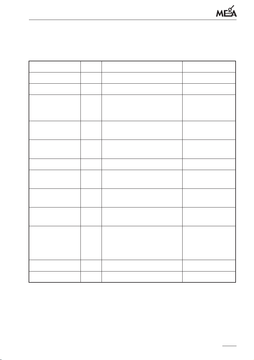
Uncertainties of measurement and measuring parameters of voltage quality in the
testing states 1, 2, 3 according to the standard EN 61000-4-30, ed. 2
LV, MV, HV level, f = 50 Hz
Parameter Class Uncertainty Measuring range
Frequency A ± 2 mHz 42.5 Hz – 57.5 Hz
Voltage A ± 0.1 % U
Flicker P
st
A 5 % P
st
IEC 61000-4-15, ed. 2
n
10 % Un – 150 % U
Pst (0.2 – 10.0)
1 – 4 000
changes/min
Flicker P
inst, max
A 8 % P
st
P
= 1.0
st
sinus, right-angle
Voltage phenomena A Amplitude: ± 0.2 % U
Duration: ± 1 period
n
5 % Un – 150 % U
0.02 sec – 60 sec
n
Interruption A Duration: ± 1 period 0.02 sec – 180 sec
Asymmetry A ± 0.1 % 0.5 % u
0.5 % u0 – 5 % u
Harmonic voltages A 5 % U
0.05 % Un, U
Interharmonic
voltages
A 5 % U
0.05 % Un, U
Signals in voltage A ± 5 % U
3 % Un ≤ U
harm
harm
sig
, U
harm
harm
, U
harm
harm
for
≤ 15 % Un,
sig
≥ 1 % U
< 1 % Un
≥ 1 % U
< 1 % U
n
10 % – 200 % class 3
IEC 61000-2-4
n
n
10 % – 200 % class 3
IEC 61000-2-4
0.5 % Un – 15 % U
– 5 % u
2
2
0
± 0.15 % Un pro
1 % Un ≤ U
≤ 3 % U
sig
n
Voltage deviations A ± 0.1 % Un 10 % Un – 150 % Un
Time base
1)
S ± 1 sec in 24 hrs -
n
n
1)
without GPS connection
29
Page 30

REFERENCES
[1] User description of SW PQ, www.e-mega.cz
[2] User description of Data Viewer, www.e-mega.cz
[3] User description of WebDatOr, www.e-mega.cz
MANUFACTURER
MEgA – Měřící Energetické Aparáty, a.s.
664 31 Česká 390, Czech Republic
Tel. +420 545 214 988
e-mail: [email protected]
web: www.e-mega.cz
Měřící Energetické Aparáty
30
Page 31

Page 32

PQ monitor MEg39
User manual
Měřící Energetické Aparáty, a.s.
664 31 Česká 390
Czech Republic
www.e-mega.cz
Edition: 2/2014
 Loading...