

Page 1
MEgA – Měřící Energetické Aparáty, a.s.MEgA – Měřící Energetické Aparáty, a.s.
664 31 Česká 390664 31 Česká 390
Czech RepublicCzech Republic
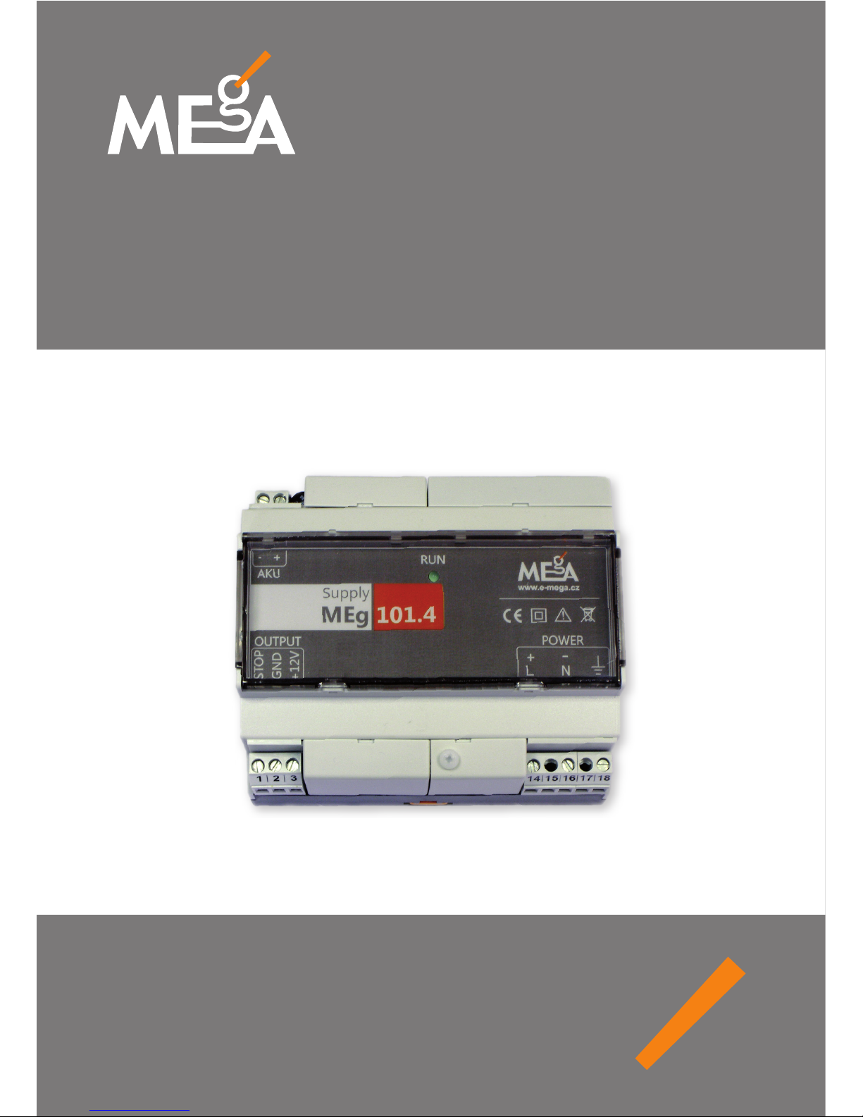
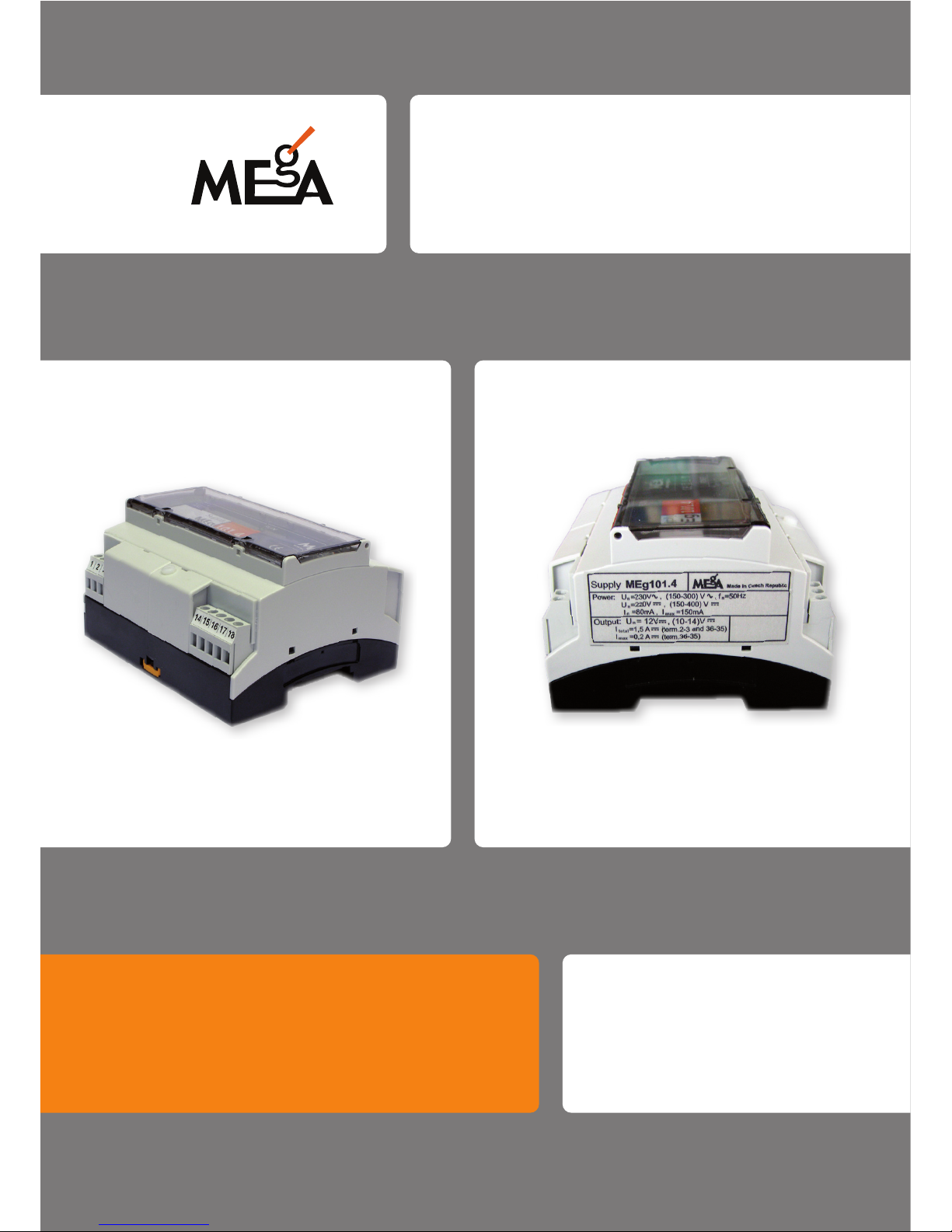
Uninterruptible power supply
Supply MEg101.4
Page 2

Page 3

Uninterruptible power supply Supply MEg101.4
3
Uninterruptible power supply
MEg101.4
1/ CHARACTERISTICS
e uninterruptible power supply MEg101.4 is designed for feeding the measuring and
communication devices with 12 V nominal supply voltage. Its core is a High-frequency voltage converter that converts the supply voltage with high eciency to the output
uninterruptible DC voltage. When the supply voltage is interrupted, the power supply
delivers the output DC voltage from the internal supercapacitor for 3 sec at least or if
an external a 12 V lead-acid accumulator is connected, it will extend duration of power
supply according its capacity. If necessary, the uninterruptible power on the output of
the power supply unit can be blocked. e output of the power supply is equipped with
overcurrent protection and with a replaceable fuse on the input accessible from outside.
e accumulator circuit is also equipped with a replaceable fuses. MEg101.4 also meets
requirements of overvoltage category CAT IV / 300 V and therefore is suitable do LV distribution networks.
Page 4

Měřící Energetické Aparáty
4
2/ TECHNICAL DATA
Power supply MEg101.4 input
Supply voltage: DC AC, f = 50 Hz
Rated voltage: 220 VDC 230 V
AC
Minimum voltage: 150 VDC 150 V
AC
Maximum voltage: 300 VDC 300 V
AC
Rated current: 180 mADC 180 mA
AC
Maximum current: 250 mADC 250 mA
AC
Input power: 20 W / 45 VA
Insulation voltage: 5.4 kVAC
Overvoltage category: CAT IV / 300 V
AC
Fuse FU1: FSK001 / 1 A-T
Accumulator
Type, rated voltage, capacity: lead-acid, gel type, 12 V, 1.2 Ah to 24 Ah
Fuse FU2: FSK001 / 2,5 A-T
Fuse FU3: FSK001 / 0,16 A-T
Power supply MEg101.4 output
Rated output voltage: 12 V
DC
Output voltage range: 10 VDC to 14 VDC
Maximum output current,
terminals 2, 3: 1.3 A
Rated power: 15 W
Uninterrupted power supply period: 3 sec. / without external accumulator connected
up to 4 hrs / when 6 Ah accumulator is connected
Max. accumulator charging current,
AKU, terminals 35, 36: 0.2 A
Starting current inrush: 5 A / 3 ms
Page 5

Uninterruptible power supply Supply MEg101.4
5
Design data
Length × width × height: 108 × 90 × 63 mm
Weight: 0.4 kg
Installation: DIN rail TS 35
Terminal block,
max. wire cross-section: 4 mm
2
Operating conditions
Rated operating temperature: 22 °C
Operating temperature range: -20 °C to +55 °C
Operation: interior, with cover panel of terminals
outdoor, in waterproof case
Protection rating: IP00
Relative humidity: 20 % to 90 %
Altitude: up to 2 000 m
Operating position: vertical with ventilation openings on upper side,
installation on DIN rail
Safety: EN 61010-1:2010
EMC: EN 61326-1:2013
Pollution degree: 2
Page 6
Měřící Energetické Aparáty
6
3/ EXPLANATION OF SYMBOLS IN USER MANUAL
FOR POWER SUPPLY MEg101.4
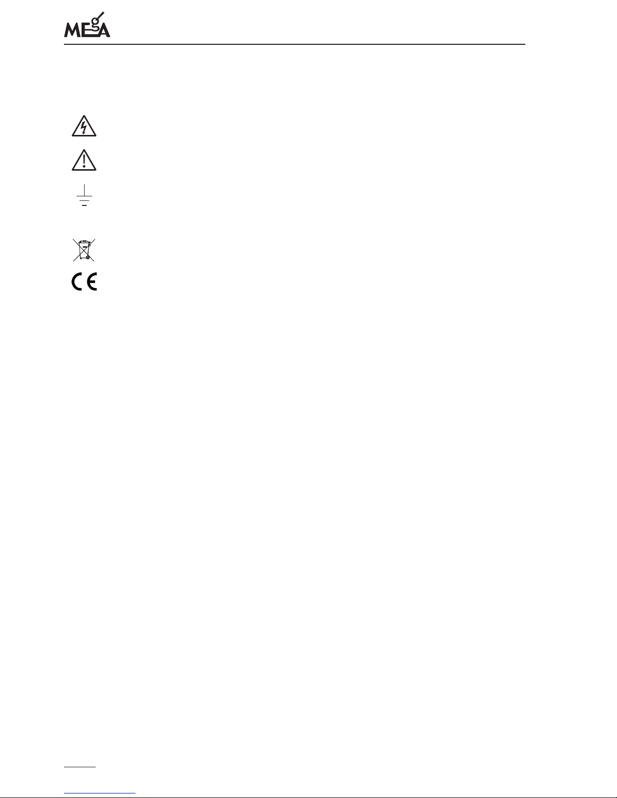
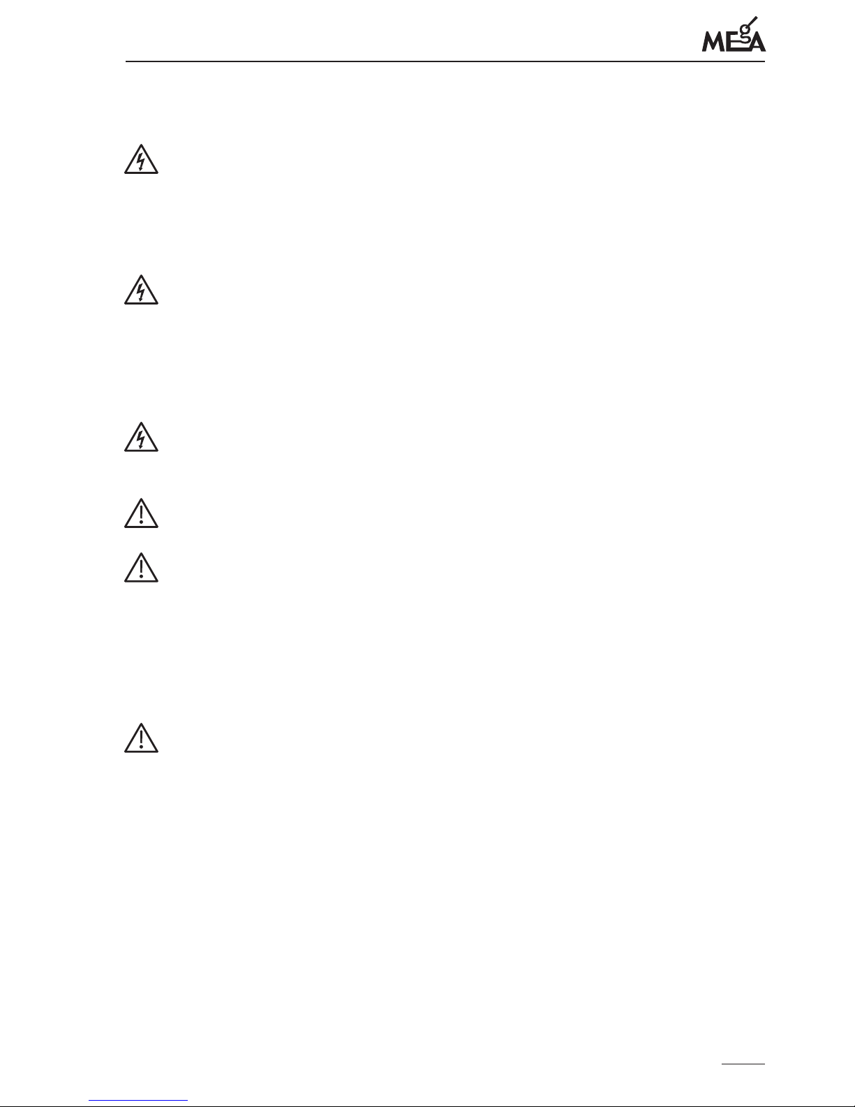
Danger, electric shock risk
Note in documentation / Danger, risk of danger
Ground, grounding terminal for RF grounding
IP kód
Degree of protection provided by enclosure
e product is intended for recycling and collection spots
Declaration of Conformity – European Community
4/ CONSTRUCTION
e uninterruptible power Supply MEg101.4 is built in a plastic case made of self-extinguishing polycarbonate. e power supply is installed on the DIN rail TS 35 using upper
or lower spring latches. e power supply can be located in the case together with the
external accumulator.
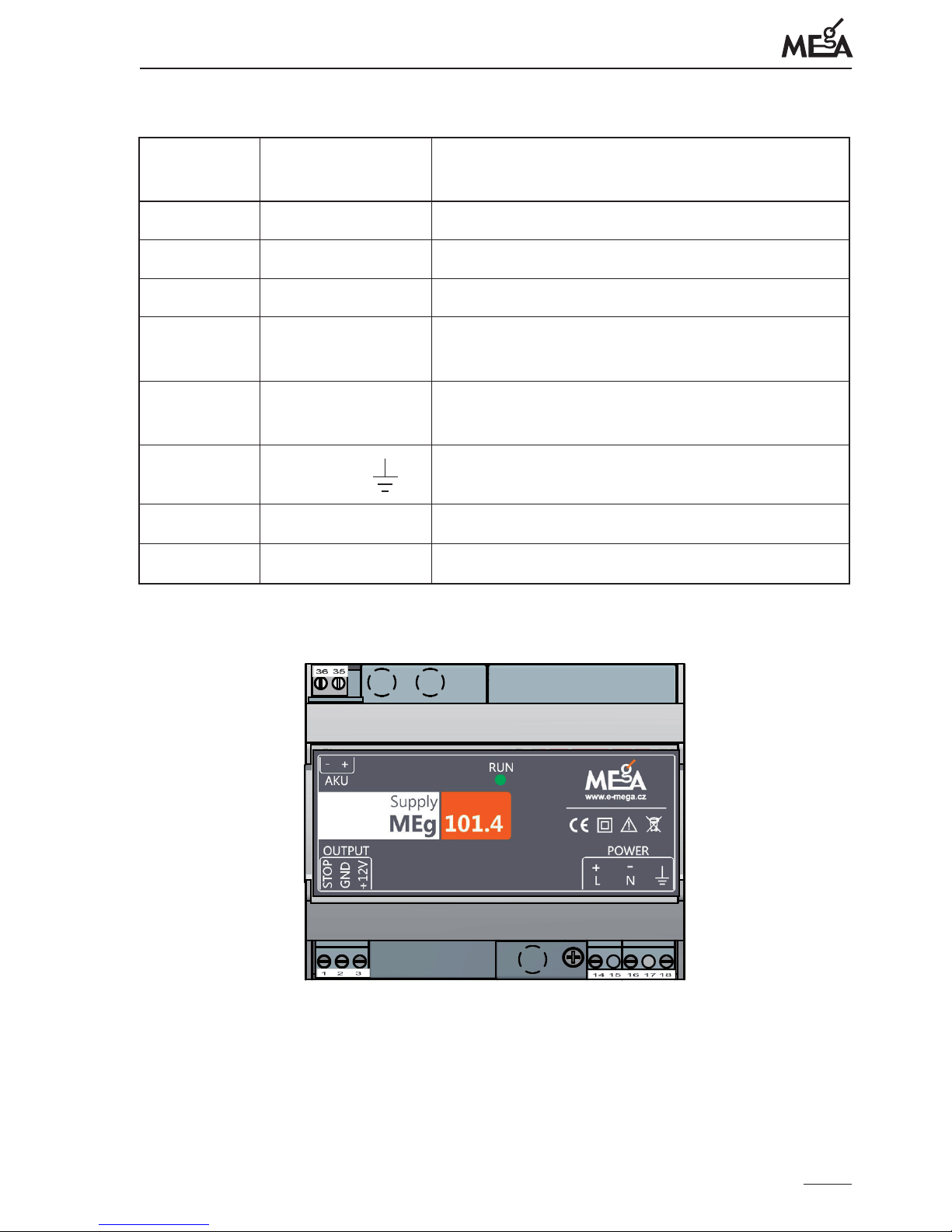
Global conguration of the MEg101.4 power supply is on Fig. 1. e LED indicator RUN
is on the unit's panel, indicating the presence of 12 V
DC
voltage on the output of the units on
terminals with label OUTPUT. e group of terminals POWER with AC or DC supply
voltage and the group of OUTPUT terminals with 12 VDC output voltage and blocking
are located on the lower part of the unit and their denotation and explanation are given
in Tab. 1. e group of AKU terminals is designed for possible connection of an external
accumulator and it is found on the upper part of the unit. Maximum cross-section of the
connected wire is 4 mm2. e replaceable input fuse FU1 is in socket under the screwed
cover next to the input supply POWER voltage terminals. Both replaceable fuses FU2 and
FU3 in the external accumulator circuit are found under the cover located next to the group
of AKU terminals. e rated voltage of the external gel gas-tight lead-acid accumulator is
12 VDC and the accumulator can have the capacity up to 24 Ah. Without the external accumulator, the supercapacitors used in the uninterruptible power supply provide power with
the voltage drop from 12 V to 10 V for 3 sec at 15 W load.
Page 7
Uninterruptible power supply Supply MEg101.4
7
Tab. 1: Power supply MEg101.4 terminals
Terminal
number
Terminal
denotation
Terminal description
1 OUTPUT STOP Uninterruptible output voltage blocking
2 OUTPUT GND Output ground of power supply MEg101.4
3 OUTPUT +12 V Uninterruptible output voltage +12 V
DC
14
POWER L
POWER +
AC phase conductor or
DC supply voltage positive pole
16
POWER N
POWER
–
AC neutral conductor or
DC supply voltage negative pole
18
POWER
RF grounding
35
AKU
+
Positive pole of the 12 V lead-acid accumulator
36
AKU
–
Negative pole of the 12 V lead-acid accumulator
Fig. 1: Power supply MEg101.4 unit
FU2
FU1
FU3
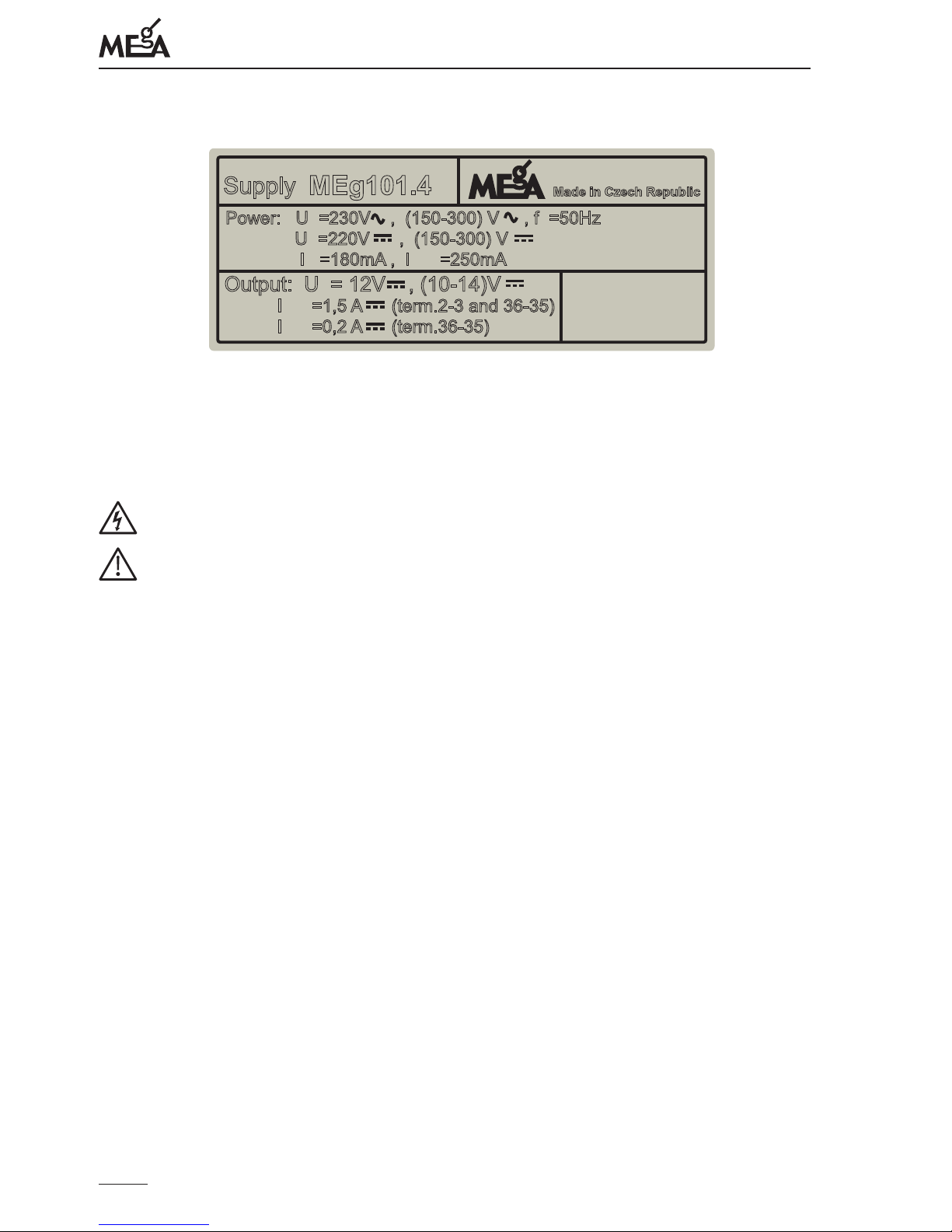
On the left side of the MEg101.4 power supply unit, there is a rating label with detailed
information about the power supply, see the example in Fig. 2.
Page 8
Měřící Energetické Aparáty
8
Obr. 2: MEg101.4 rating label example
MEg101.4
Made in Czech Republic
Supply
P
ower: U =230V , (150-300) V , f =50Hz
n
O
utput: U = 12V , (10-14)V
n
max
U
=220V , (150-300) V
n
I
=180mA , I =250mA
n
max
I
=1,5 A (term.2-3 and 36-35)
total
I
=0,2 A (term.36-35)
n
5/ SAFETY INFORMATION
Maximum attention must be paid to this information
Warnings draw attention to the facts, constituting safety risks to the operator.
Cautions indicate conditions and facts that may cause damage to the uninterrup-
tible power supply MEg101.4.
• e operator engaged in installation of the power supply MEg101.4, commissioning, maintenance and dismantling must be equipped with personal protective
equipment against electrical shock and must use other protection devices as well.
• e operator engaged in installation of the power supply MEg101.4, commissioning, maintenance and disassembly must have qualications for work near dangerous voltages. e operator must also be trained to administer rst aid.
• e power supply MEg101.4 may be operated by skilled personnel only.
• e power supply MEg101.4 may be connected to supply by permanent maximum
voltages 300 V
AC
and 300 VDC, otherwise there is a risk of electrical injury.
• It is necessary to incorporate circuit breakers in the circuits of the power supply
MEg101.4 with respect to the type of supply voltage, see Fig. 4.
• Repairs of the power supply MEg101.4 may only be carried out by the manufacturer or service organizations authorized by the manufacturer.
• e replacement of FU1 fuse for AC or DC supply voltage may be carried out only
with the supply voltage switched o.
• When connecting an external 12 V battery the terminals must not to be short circuited and as the last the inlet connects to positive pole of the supply source.
Page 9
Uninterruptible power supply Supply MEg101.4
9
6/ INSTALLATION AND PUTTING IN OPERATION
If the uninterruptible power supply MEg101.4 is used in ways other than origi-
nally intended, the protection provided by the power supply may be impaired.
e uninterruptible power supply MEg101.4 is a Class A product designed
for industrial environments. It may cause radio interference in other environments.
e power supply MEg101.4 unit is placed only in vertical position and is always
installed on DIN rail (35 mm) in the case or under the terminal cover panel so that
protection rating, re resistance, mechanical impact resistance for the required
environment can be reached. Due to protection against electrical injury and mechanical impact resistance improvement require overlapping the terminals cover
by the cover panel.
e uninterruptible power supply MEg101.4 may only be installed by the per-
son authorized to work with input voltage and equipped with personal protection
equipment against electrical injury and familiarized with the instruction manual.
e denotation of supply terminals in the POWER L and N section applies to AC
mains supply and the denotation + and – applies to DC supply voltage.
e power supply MEg101.4s with the external lead-acid accumulator is delivered
unconnected. When handling the accumulator, its output terminals must not be
short-circuited. When installing the MEg101.4 set with the external accumulator,
the correct polarity must be respected. In case of incorrect connection of the
accumulator to the power supply terminals (terminal 35 is + pole, terminal 36 is
–pole), the fuse FU2 (2.5 A) will burn out. In case of short-circuit of the accumulator terminals (terminals 35 and 36) the fuse FU3 (0.16 A) will burn out.
Regardless of the power supply voltage direction or way of grounding (DC or AC,
none or one grounded pole), it is neccessary to connect both supplying wires via
fuse switch-disconnector according to Fig. 4.
It is also neccessary to place the fuse switch-disconnector as close as possible and
as easily reachable as possible.
e uninterruptible power supply MEg101.4 is installed always on the DIN rail TS 35.
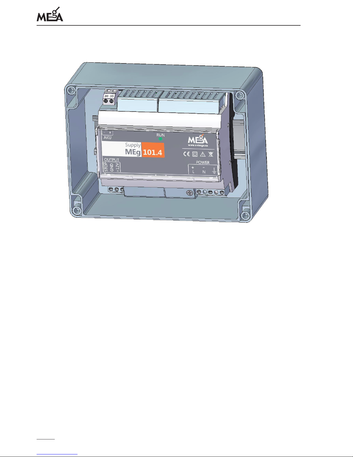
e MEg101.4 is always in vertical position with ventilation openings on upper side and
the inscription on the unit's panel is readable from left to right, see Fig. 3.
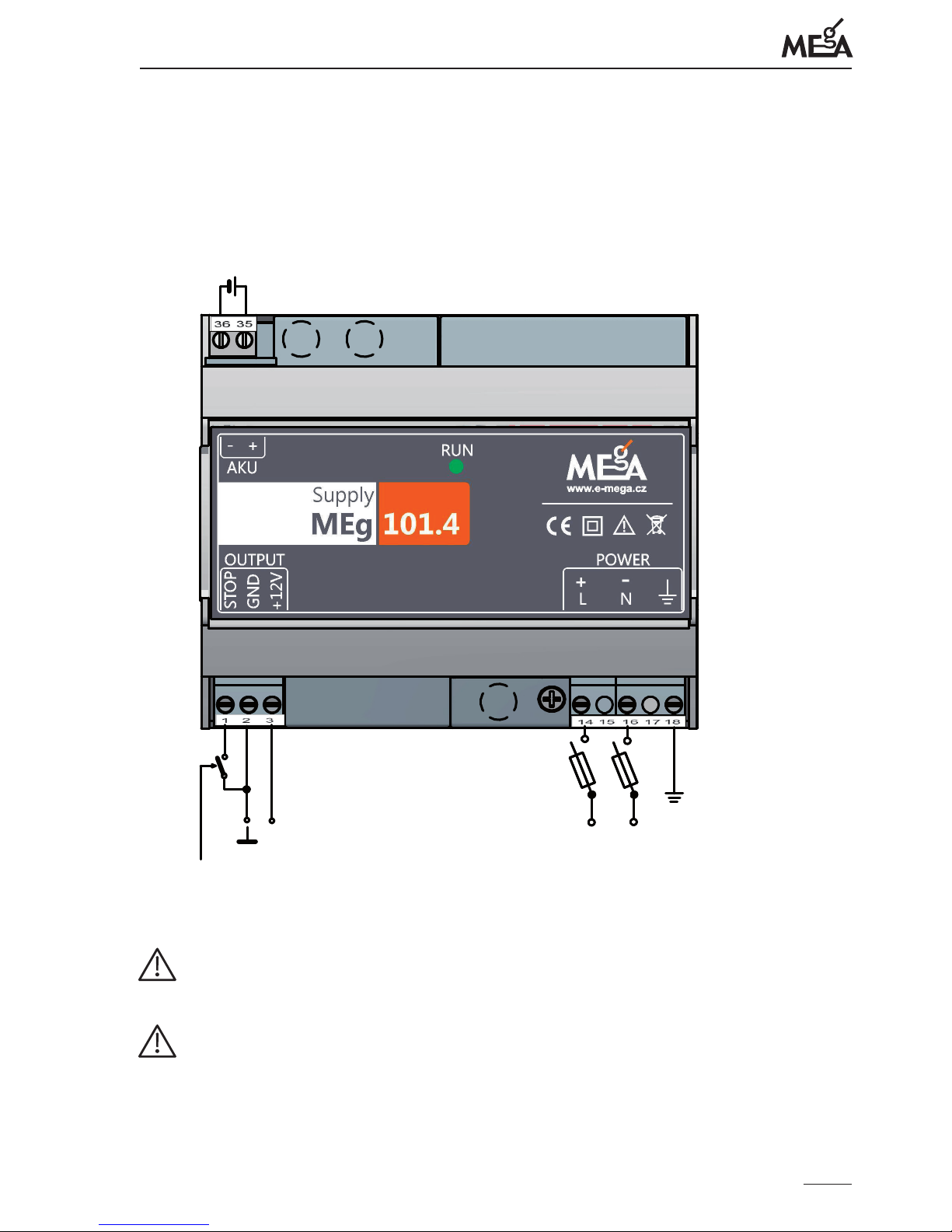
Power supply MEg101.4 wiring is in Fig. 4.
Page 10
Měřící Energetické Aparáty
10
Fig. 3: Example of installation source unit in vertical position to box with DIN rail
e power supply terminal (18) for RF grounding must be connected to the grounding
system in the power supply installation site.
Based on the type of power supply, AC or DC supply voltage is brought to terminals (14)
and (16). e power supply MEg101.4 can be fed by AC voltage ranging from 150 VAC
to 300 VAC.
e power supply MEg101.4 can be fed by DC voltage ranging from 150 VDC to 300 VDC.
When the uninterruptible power supply MEg101.4 is used for feeding external devices,
the uninterruptible output voltage is +12 V / max. 1.3 A is available at terminals (2) and
(3). e terminal (1) connected with terminal (2) is used for blocking the uninterruptible
supply voltage. In this way, it is possible to block unnecessary discharging of the external
accumulator, e.g. during functional checks and inspections.
After connection of the input supply voltage, the LED indicator RUN on the power
supply panel is lit and the output DC voltage U
nom
= +12 VDC is available on the output
and internal supercapacitors and also alternatively the external lead-acid accumulator
connected are charged at the same time. When the supply voltage is interrupted, the
power supply unit is fed by DC output voltage ranging from 10 V to 14 V for the period of
Page 11
Uninterruptible power supply Supply MEg101.4
11
uninterruptible power supply. e termination of uninterruptible power supply is indicated by the LED indicator RUN turned o. Renewal of the uninterruptible power supply
is started up also by short-term renewal of the input supply voltage.
Fig. 4: Power supply MEg101.4 wiring
Lead-acid Accu
12V, max.24Ah
DC
+12V
+/L -/N
150V to 300V
150V to 300V ,50Hz
DC
DC
AC
AC
Power
STOP 12V
DC
FU1
FU2
FU3
e discharged accumulator with capacity 6 Ah is fully charged in 48 hours even
with maximum load of the power supply.
e uninterruptible power supply MEg101.4 has an internal power source (superca-
pacitors) so it is not permitted to remove its cover when it is in operation.
Page 12
Měřící Energetické Aparáty
12
7/ MAINTENANCE REQUIREMENTS
e repairs of the power supply MEg101.4 during the warranty period may only
be carried out by the manufacturer's skilled and trained personnel or by the manufacturer's service organizations. e contact to the manufacturer's service is indicated on the website www.e-mega.cz.
e power supply MEg101.4 unit may not be exposed to chemicals.
e power supply MEg101.4 may be transported in its original container only.
e power supply MEg101.4 has no requirements for forced cooling.
When polluted, the power supply unit is carefully cleaned with a damp cloth wi-
thout using cleaning agents.
When the power supply MEg101.4 with external lead-acid accumulator is stored
for a long time or the input voltage is not connected, it is necessary to charge the
battery, preferably through the MEg101.4 power supply, after 1 year at the latest.
e minimum charging time for the 6 Ah accumulator is 48 hours. When an external lead-acid accumulator with a dierent capacity is connected, the charging
time will be modied proportionally.
It is recommended to perform preventive inspections after every 4 years of operation.
e preventive inspection includes:
• checking the unit for mechanical integrity,
• checking the level of output DC voltage,
• checking the output DC voltage blocking by connecting the power supply contacts
(1) and (2) with disconnected supply voltage,
• checking the capacity of the external lead-acid accumulator or preventive replacement of the accumulator.
• When the power supply is used without the external accumulator connected, check
the function of the uninterruptible power supply from internal supercapacitors in
such a way that the power supply is connected for 10 minutes to the supply voltage
and then the time of uninterruptible power supply is checked according to loading
level, see Tab. 2.
Page 13

Uninterruptible power supply Supply MEg101.4
13
Tab. 2: Informative periods of uninterruptible power supply without connected
external accumulator with voltage drop to 10 V
P [W] 10 15
t [sec] 8 4
8/ DISPOSAL
When the power supply MEg101.4 service life is over, have the unit recycled in waste
disposal sites according to rules for electronic waste disposal. e power supply set may
include the accumulator as well.
9/ CONTENTS OF THE SET
Basic set
– Uninterruptible power supply MEg101.4
– 1 pc fuse FU1 type FSK 001 / 1 A-T
– 1 pc fuse FU2 type FSK 001 / 2,5 A-T
– 1 pc fuse FU3 type FSK 001 / 0,16 A-T
– CD with user description
Optional parts of the set
– DIN rail TS 35 with accessories
– n pc fuse FU1 type FSK 001 / 1 A-T
– n pc fuse FU2 fuse type FSK 001 / 2,5 A-T
– n pc fuse FU3 type FSK 001 / 0,16 A-T
– 2-pole disconnector OPVA 10-2
Page 14

Měřící Energetické Aparáty
14
10/ WARRANTY
It is not permitted to open the power supply MEg101.4 during warranty period.
e power supply MEg101.4 design is covered by a 24-month warranty from the date of
purchase, however, 30 months after removal from the manufacturer storage at longest.
Defects originating during this period as a demonstrable result of defective design, manufacturing or using improper material will be repaired free of charge by the manufacturer
or his service organization e external lead-acid accumulator delivered in the MEg101.4
power supply set is covered with a warranty in compliance with delivery terms of the
accumulator supplier.
During the warranty period, after 1 year at the latest, it is necessary to connect the power
supply with the external lead-acid accumulator to the rated supply voltage for 48 hours
at least.
e warranty becomes invalid if the user carries out unauthorized modications or changes on the power supply if he connects the power supply incorrectly or if operated contrary to technical conditions and user description.
e defects on the power supply and its accessories originating during the warranty period shall be claimed by the user to the manufacturer or to the service organization authorized by the manufacturer.
e manufacturer bears in any case no responsibility for subsequent damages caused by
using the MEg101.4 power supply.
No responsibility which would exceed the price of the power supply follows for the manufacturer from this guarantee.
11/ MANUFACTURER
MEgA – Měřící Energetické Aparáty, a.s.
664 31 Česká 390, Czech Republic
tel. +420 545 214 988
e-mail: [email protected]
www.e-mega.cz
Page 15

Page 16
MEgA – Měřící Energetické Aparáty, a.s.
664 31 Česká 390
Czech Republic
www.e-mega.cz
Edition: 7/2015
Uninterruptible power supply
Supply MEg101.4
 Loading...