

Mega H-550A Instruction Manual

AUTOMATIC BANDSAW
H-550A
INSTRUCTION MANUAL
MEGA MACHINE CO., LTD.
DOC NO
:
H550A-100.U
CTRL NO
:
06
UPDATE
:
1998/07/27
DOC VER
:
A

FOREWORD
We hope that the owner of this heavy-duty bandsaw machine will
have years of trouble-free service. The machine has been built
to the highest standards to enable fast accurate cutting to be obtained.
In order that the best results can be achieved from your MEGA band
saw we would ask all operators and maintenance engineers to READ
THIS MANUAL CAREFULLY BEFORE STARTING UP THE MACHINE.
The manual contains full instructions on installation, operation, lubrication,
maintenance and trouble-shooting.
As MEGA MACHINE COMPANY LIMITED is constantly improving the
design of its machines, there may be some instance where this book differs
somewhat from the machine with which you are concerned. So, always
quote the Serial Number of your machine, when ordering spare parts
or in correspondence relating to the machine.
MODEL : H550A
Serial Number :
Request for service and spare parts should be made to :
ADDRESS: NO. 180, INDUSTRIAL ROAD, TAI-PING CITY, 41107 TAICHUNG,
TAIWAN R. O. C.
E-MAIL: mega@ms1.hinet.net; mega@mail.mold.net.tw
URL: www.bandsaw.com.tw
TEL: 886 4 22712877(PRES.) FAX:886 4 22715016

TABLE OF CONTENTS
Item
Unit
Page
1 Introductory Illustrations 1-1
1.1
Principal parts
1-1
2 Specifications
2.1 Specifications 2-1
2.2 Standard Accessories 2-1
3 Installation
3.1 Moving and lifting 3-1
3.2 Foundation layout and Set-up 3-2
3.2.1 Foundation 3-2
3.2.2 Leveling 3-3
3.2.3 Cleaning and oiling 3-3
3.2.4 Power Source Connection 3-4
4 Operation
4.1 Control Panel 4-1
4.2 Operating preparation 4-3
4.3 Manual Operation 4-4
4.4 Automatic operation 4-5
4.5 Special Operation 4-5
4.6 Break -In Operation 4-5
5 Maintenance
5.1 Hydraulic Circuit 5-1
5.2 Oiling and Lubrication 5-2
5.3 Others 5-3
6 Trouble Shooting Guide
6.1 Sawing Problems and Solution 6-1
6.2 Minor Operating Troubles and Remedies 6-2
6.3 Error information 6-3
7 Reference Charts
7.1 Standard cutting Chart 7-1
7.2 Standard cutting Chart 7-2
7.3 Standard cutting Chart 7-3
Electrical Circuit
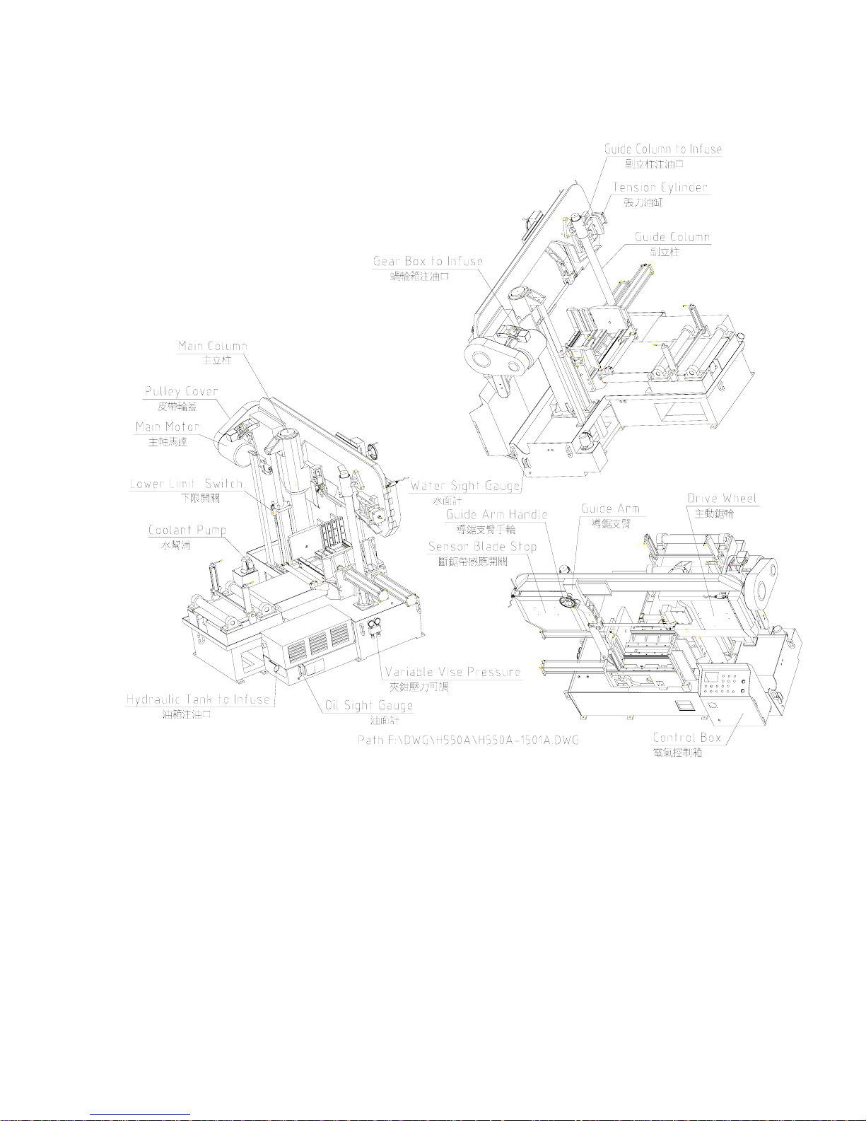
1. INTRODUCTORY ILLUSTRATIONS
1.1 Principal Parts
1 – 1

2. SPECIFICATIONS
2.1 SPECIFICATIONS
Model
Specifications
H-550A / H-550GA
(mm)
φ550 □550H*600W
(in)
Max
φ21 □21*23
(mm)
φ190 □ 550H * 190W
Cutting Capacity
(in)
Min
φ7.48 □ 21H * 7.48W
Bundle Cutting (mm) 250H*440W
(mm) 41W * 1.30t * 5800L
Blade Size
(in) 1-1/2W * 0.051t * 226L
(m/min ) 25,32,42,55,70,80
Blade Speed
(ft/min) 82,105,138,180,230,260
(kW) Blade 5.6 Hydraulic1.5 Coolant0.1
Motor Output
(HP) Blade 7.5 Hydraulic 2 Coolant 1/8
Hydraulic pressure (bar) 40
(kg) Net / Gross 3800 / 4500
Weight
( lb. ) Net / Gross 8360 / 9900
* Specifications subject to change without notice for improvement and modification.
2.2 STANDARD ACCESSORIES
1. Tools with tool box ..................... 1 set
2. 7 ft.(2M) long roller table ............. 1 set
3. Band-cleaning wire brush ................ 2 pieces
4. Band saw blade .......................... 1 piece
5. Vertical guide rollers .................. 1 set
6. Instruction manual ...................... 1 copy
2-1
3. INSTALLATION:
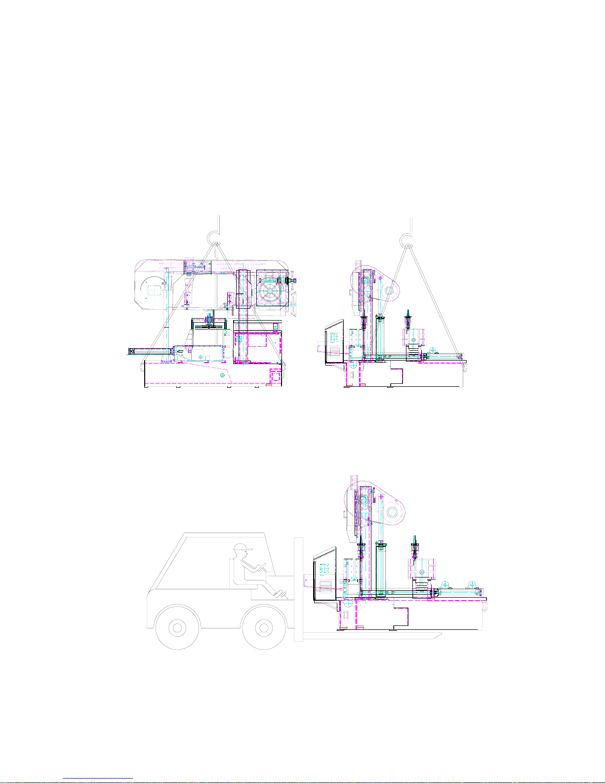
3.1 Moving and lifting:
Unpack your machine carefully, and use a crane or forklift to set it in position.
If a crane is used to lift the machine attach the lifting cable carefully to the machine as shown in the
fig 2. If forklift is used then fig 3.
Sufficient space should be left around the machine to allow safe handling of materials , and inspection
and maintenance operation. Should there be other machinery causing vibration or dust that near your
machine ,then precautions must be taken to keep your machine away from of vibration and dust.
(1) Use Crane :
Fig 2
(2) Use Forklift :
Fig 3
3 - 1
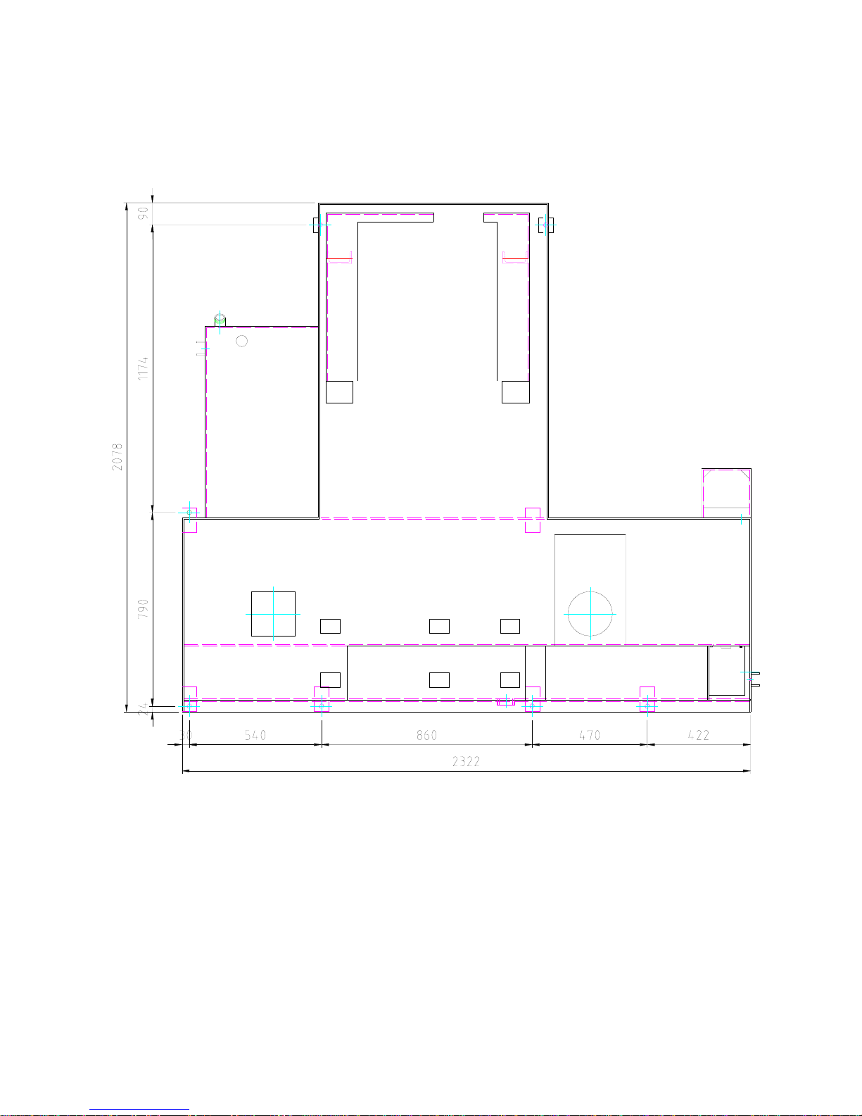
3.2 Foundation layout and set-up:
(1) Foundation:
The foundation should be constructed of reinforced concrete and must be level and flat. After the proper
leveling position has been obtained, anchor the machine with anchor bolts. The position of anchor bolts
and floor dimensions are shown in fig 4:
□ Contact portion with floor
○ Position of anchor bolts
Fig. 4
※ All leveling bolts should support the weight of the machine evenly .
3 ─ 2
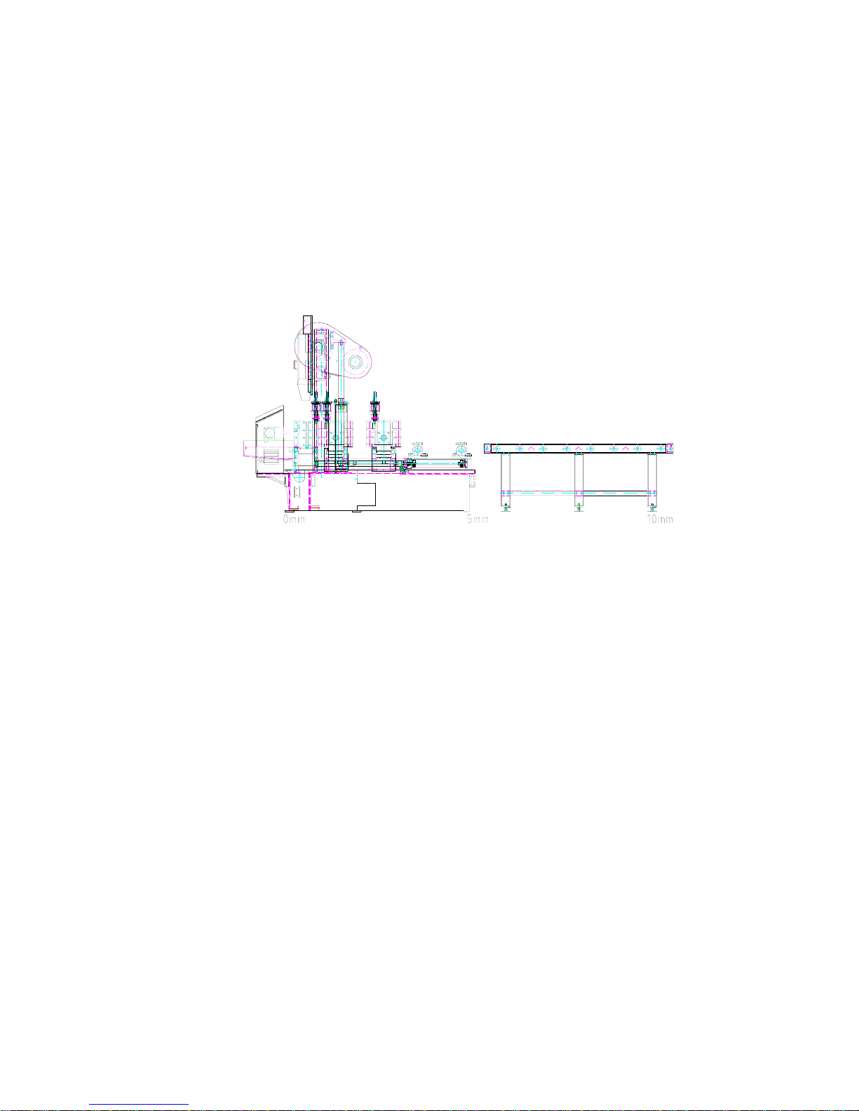
(2) Leveling:
The production accuracy of all precision machinery depends on the accuracy which the machine is
installed. Manufacturing tolerance of the machine can only be guaranteed if the machine is firmly and
properly installed . Once the machine is lowered on the prepared foundation. Machinist levels should be
Used alternately on the vise slide plates and the work feed table , and adjust the left-and-right and
fore-and-aft level of the machine with leveling bolt .
The fore-and-aft level should be adjusted so that the level of the rear end is approximately 10 mm (3/8" -
1/2") higher than the level of the front end , to provide proper return of the cutting fluid , and easy
operation of car feeding .
The left-and-right level should be adjusted so that the level of the left end is approximately 3 mm (1/8")
higher than the level of the right end , to provide proper return of the cutting fluid , After the proper
leveling position has been obtained anchor the machine with anchor bolts .
CAUTION : All leveling bolts should support the weight of the machine evenly .
Leveling as fig 5 below :
FIG 5
(3) Cleaning and oiling :
After the machine has been placed in position , thoroughly remove its rust preventive coating using a
suitable cleaning solvent and then apply a coat of machine oil . To clean the machine , Kerosene is
preferable to gasoline . It does not evaporate and level dried slushy compound on finished surfaces.
Rags are better than waste as they leave no lint or strings. The machine as received by you. has been
completely drained of all oil. Before any attempt is made to run it . Before any motor connections are
made .... every detail of the following oiling instruction must be complied with. Refer to the oiling chart in
chapter 7. Especially, don't forget to fill up the cutting fluid mixture. Usually, the ratio of cutting fluid to
water should be 1:30 - 1:50. Check the sight gauge to ascertain the fluid level in the tank every day.
Transmission gear box, bar feed gear box, hydraulic oil tank should to topped up monthly. Oil levels
should
be strictly observed, for it is of primary importance for proper operation and long life.
(4) Power Source Connection :
A. Power Source - This machine is equipped with 7.5HP main motor and 2HP hydraulic motor, and
1/8HP coolant pump. Connect the power supply cable to the circuit breaker (N.F.B.) terminals.
The power supply to your machine should agree with the wring voltage that is indicated on the label
attached to the electrical enclosure and main motor.
B. Earth - Be sure to connect the earth cable to the earth terminal.
C. Starting - After making the necessary wiring connections, turn the power switch on the control panel
clockwise to turn power on, depress the vise limit switch (if necessary, e.g. if there is no stock bar clamped
in the vise) and push the button to see if the saw head moves upward.
If the saw head does not rise , the hydraulic pump motor is rotating in the wrong direction.
If the motor runs in the wrong direction, turn off the power switch and disconnect the power supply cable,
Then interchange any two phase connections.
3 ─ 3
4. OPERATION
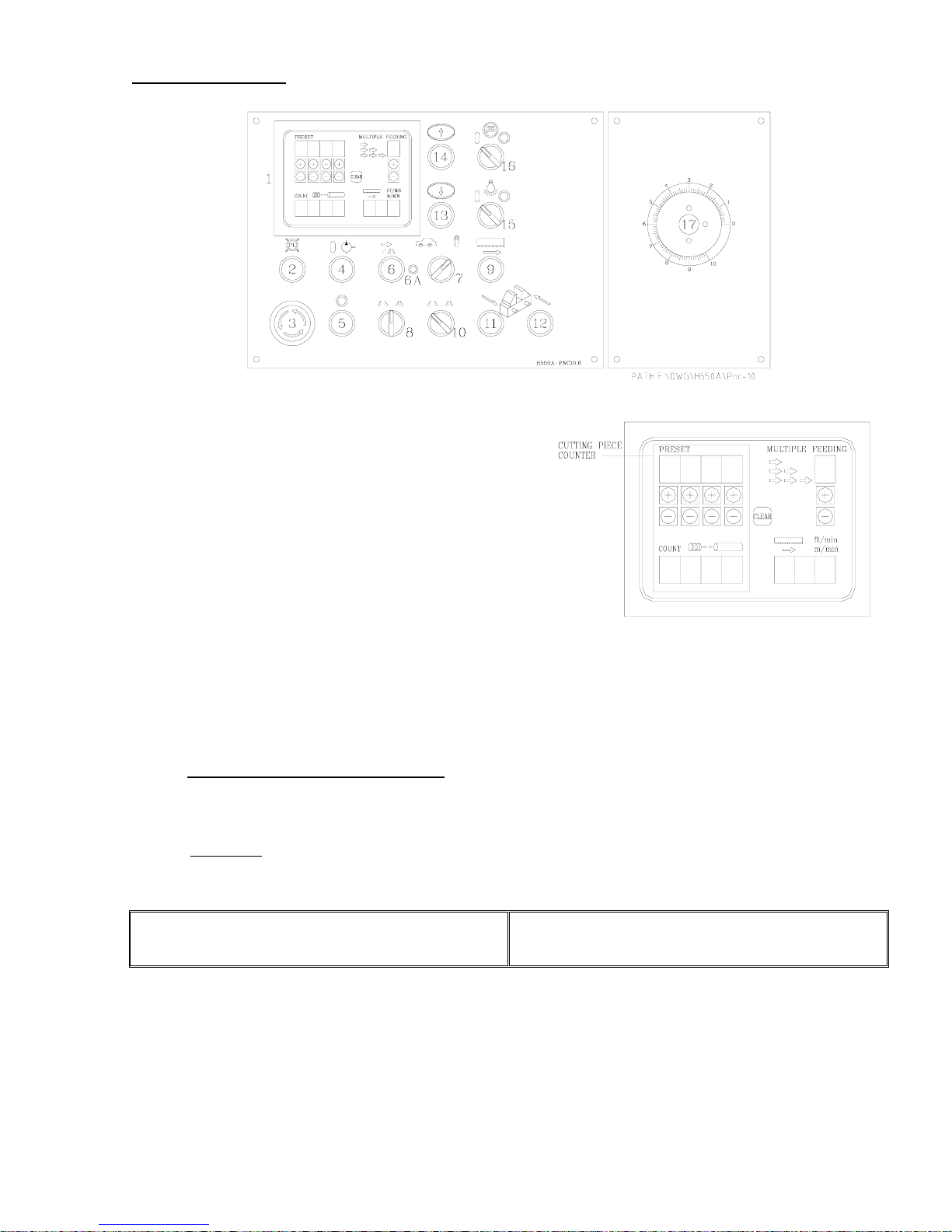
4.1 Control Panel
(1) PNC Control Panel
Cutting Piece Counter – This counter is used to preset
the number of cuts required on the automatic operation.
When the counter reaches the preset number, the machine
stops automatically . To activate the counter, preset the
counter switch with number at least “1”.
Clear – This key is used to clear the counted number cut
already and to have new number input available.
Multiple stroke feed counter – This counter makes it
possible to multiply the number of index cycles when off-cut pieces longer than 500mm are required.
Maximum 9-time stroke can be set.
Blade speed LED-Display -- This blade speed tachometer indicates how fast the saw blade is running in
meter per minute by LED display.
To see digital cut length counter
L (length req.) + K (blade thickness)
S =
N (multiple feed times)
- K
EXAMPLE:
1200 +1.5
S =
3
-1.5 = 400.5-1.5 = 399
L = Required cut length N = Multiple feeding times
K = Cutting loss ( Blade thickness ) S = Digital counter length setting
Total bar feed needed = length + blade thickness
Single step feed = length + K
Multiple step feed only needs 1 allowance for blade
Thickness ...hence…L + K divided by number of steps
Then less K = Digital counter setting length….
4 - 1
 Loading...