

Mega FSF350-6W, FSF400-6W, FSF450-6W Instruction Manual
14
INSTALLATION
* Install filtration system including pump, filter tank and multiport valve.
* The filter system should be installed as close as possible to the swimming pool and preferably at a level
of 0.50 metres below the surface of the water in the swimming pool. Make sure there is drainage available at the
place where the filter is to be installed.
* PUMP
1.Only qualified, licensed personnel should install pump and wiring.
2.Electrical Contractors Please Note: All 230 volt 50Hz pump must be wired to the main power supply trough an
approved and correctly rated contractor.
3.Allow for gate valve in suction piping.
4.Pump suction and discharge connections have moulded in thread stops, do not try to screw pipe inbeyond these
stops.
* FILTER TANK and MULTIPORT VALVE
1.Loading the sand media. Filter sand media is loaded through the top opening of the filter.
a.Loosen the plastic clamps from tank neck.
b.Cap internal pipe with plastic cap to prevent sand from entering it.
c.We recommend filling tank approximately 1/2 way with water to provide a cushion effect when the filter sand is
poured in. This helps protect the under-drain laterals from excessive shock.
d.Carefully pour in correct amount and grade of filter sand. Be sure center pipe remains centered in opening. Sand
surface should be leveled and should come to about the middle of the filter tank. Remove plastic cap from internal
pipe.
2.Assemble filter control valve to filter tank.
a.Insert filter control valve(with O'ring in place)into the tank neck, taking care that the center pipe slips into the hole
in the bottom of the valve.
b.Place two plastic clamps around valve flange and tank neck and tighten just enough so that the valve may Be
rotated on tank for final positioning.
c.Carefully screw pressure gauge(with O'ring in place)into tapped hole in valve body. Do not over-tighten.
D.Connect pump to control valve opening marked PUMP with hose. After connections are made, tighten clamps with
screwdriver, tapping around clamp with screwdriver handle to help seat valve flange clamp.
3.Make return to pool pipe connection to control valve opening marked RETURN and complete other necessary
plumbing connections, suction lines to pump, waste, etc.
4.To prevent water leakage, be sure all pipe connections are tight.
By-passes filter for circulating water to pool
Used after backwash to flush dirt from valve
Cleaning Filter by reversing the flow
By-passes filter, used for vacuuming to waste or lowering water level
CLOSED Shuts off all flow to filter or pool
RECIRCULATE
WASTE
RINSE
BACKWASH
FILTER
Valve Position
Normal Filtration and Vacuuming
Function
THIS FILTER OPERATES UNDER HIGH PRESSURE. WHEN ANY PART OF THE CIRCULATING
SYSTEM (e.g., CLAMP, PUMP, FILTER, VALVES, ETC.) IS SERVICED, AIR CAN ENTER THE
SYSTEM AND BECOME PRESSURIZED . PRESSURIZED AIR CAN CAUSE THE LID OR VALVE
TO BE BLOWN OFF WHICH CAN RESULT IN SEVERE INJURY, DEATH, OR PROPERTY
DAMAGE TURN PUMP OFF BEFORE CHANGING VALVE POSITION.
TO PREVENT DAMAGE TO THE PUMP AND FOR PROPER OPERATION OF THE SYSTEM.
CLEAN PUMP STRAINER AND SKIMMER BASKETS REGULARLY.
DO NOT UNSCREW SCREWS OF FLANGE CLAMP WHILE PUMP IS RUNNING.
WARNING
!
!
!
!
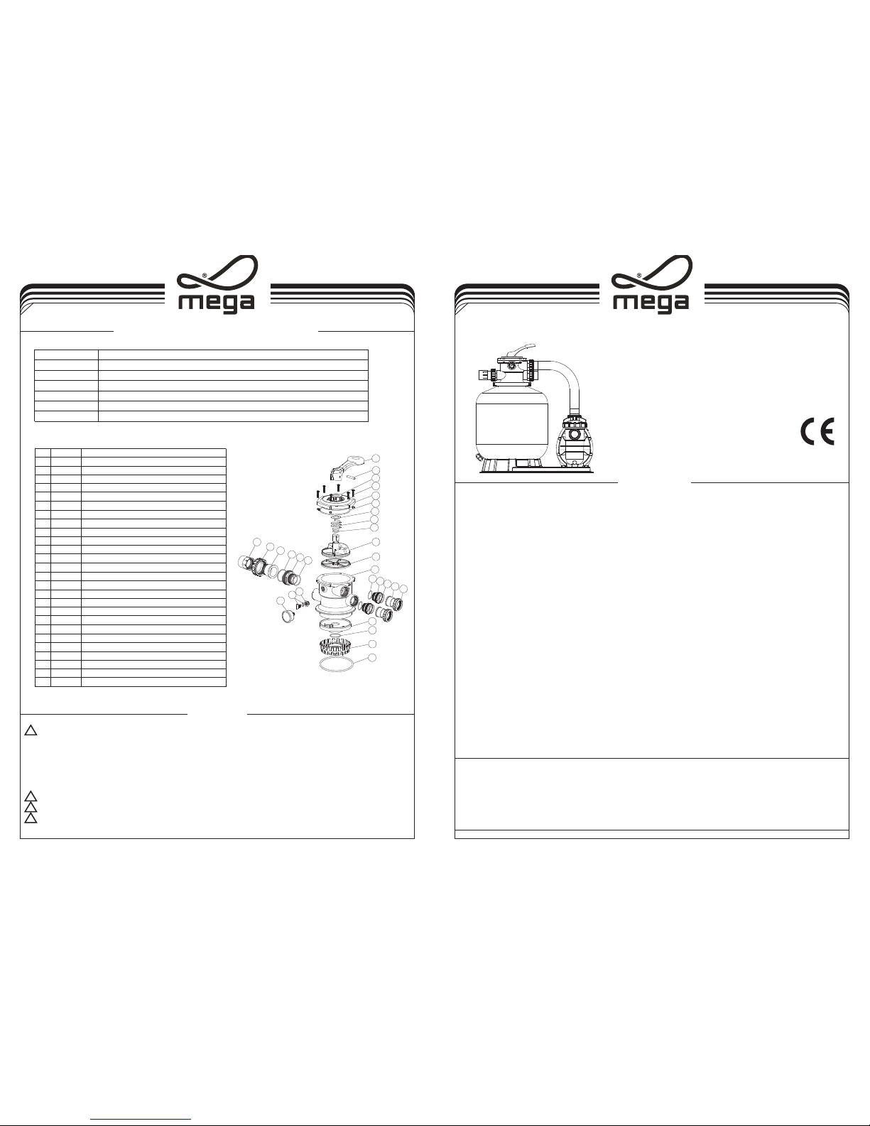
EM-MV40B VALVE REPLACEMENT PARTS
FILTER & PUMP COMBO
Installation & Operating
Instruction
MEFS10121717
FSF350-6W,FSF400-6W,FSF450-6W
17
18
19
20
21
13
14
15
16
6
12
1
2
3
4
5
7
8
9
10
11
17
18
19
22
21
23
24
25
26
Item Part No Description
1 01013003 Handle(Big)
2 03018008
Pin for Hand le
3 01181001 Washe r for Handle
4 89280107 M6×30 Screw wit h Nut for S tandard Lid
5 01013004
1.5"Top Mount Valve Standard L id (Black)
6 02011002 O-Ring for 1.5" Valve Lid
7 01181002 Washe r for Spring
8 03014001 Spring for 1.5 " Top Mount Valve
9 02011022
O-Ring for 1. 5" Valve Rotor
10 01021001 1.5" Valve Rotor
11 02311002
Spider Gasket
12 01013007
1.5"Top Mount Valve Bottom Body Clamp (Black)
13 01013011
1.5" Diffuser
14 02011001 O-Ring for Diffu ser
15 01013012 1.5"Top Mount Valve Over Drain Diffuser
16 02011134 O-Ring
17 02011151 O-Ring for 1.5"Connecto r
18 01013015 1.5"Connector (Black)
19 02011003 O-Ring for 1.5"Union
20 01171153 1.5"Union (A/E)
21 01013017 1.5"Union Nut (Black)
22 01041002 1.5"Union With Sigh t Glass (short)
23 01172026 1.5"Union With Sigh t Glass Holder
24 01111048 Connector for pressu re gauge/sto pper
25 89021703 Drain Plug with O-ring
26 06011029 Oil Pressure Gauge W ith O-ring (40Psi)
IMPORTANT NOTICE
All MEG A pumps mus t be wire d to the
Insta llati on of ele ctric al item s must co mply wi th Loca l Rules a nd Ordi nance s. Belo w infor matio n are for
refer ence on ly:
! Local R ules (U K): Accor ding to B S7671
! Local R ules (N L): Accor ding to N EN101 0
! Local R ules (B e): Accor ding to ARE I 50
main po wer sup ply wit h corre ct rati ng and by a c ertif ied ele ctric ian.
2 3
REPLACEMENT PARTS OF FILTER
1. Be sure correct amount of filter media sand is in tank and that all connections have been made and are secure.
2. Depress control valve handle and rotate to BACKWASH position. (To prevent damage to control valve seal, always
depress handle before turning.)
3. Prime and start pump. Never tun pump dry! Running pump dry may damage seals, causing leakage and flooding!
Fill pump with water before starting motor. (be sure all suction and return lines are open), allowing the filter tank to fill
with water. Once water is flowing out of the waste line, run the pump for at least 1 minute. The initial back-washing
of the filter is recommended to remove any impurities or fine sand particles in the sand media.
4. Turn pump off and set valve to RINSE position. Start pump and operate until water in sight glass is clear, about 1/2
to 1 minute. Turn pump off and set valve to FILTER position and restart pump. The filter is now operating in the
normal filter mode, filtering dirt particles from the pool water.
5. Adjust pool suction and return valves to achieve desired flow. Check system and filter for water leaks and tighten
connections, bolts, nuts, as required.
6. Note the initial pressure gauge reading when the filter is clean. (It will vary from pool to pool depending upon the
pump and general piping system.) As the filter removes dirt and impurities from the pool water, the accumulation in
the filter will cause the pressure to rise and flow to diminish. When the pressure gauge reading is 1.5 bar, higher
than the initial "clean" pressure you noted, it is time to backwash the filter (see BACKWASH under filter and control
valve functions).
NOTE: During initial clean-up of the pool water it may be necessary to backwash frequently due to the unusually
heavy initial dirt load in the water.
INSTALL/START-UP OF FILTRATION
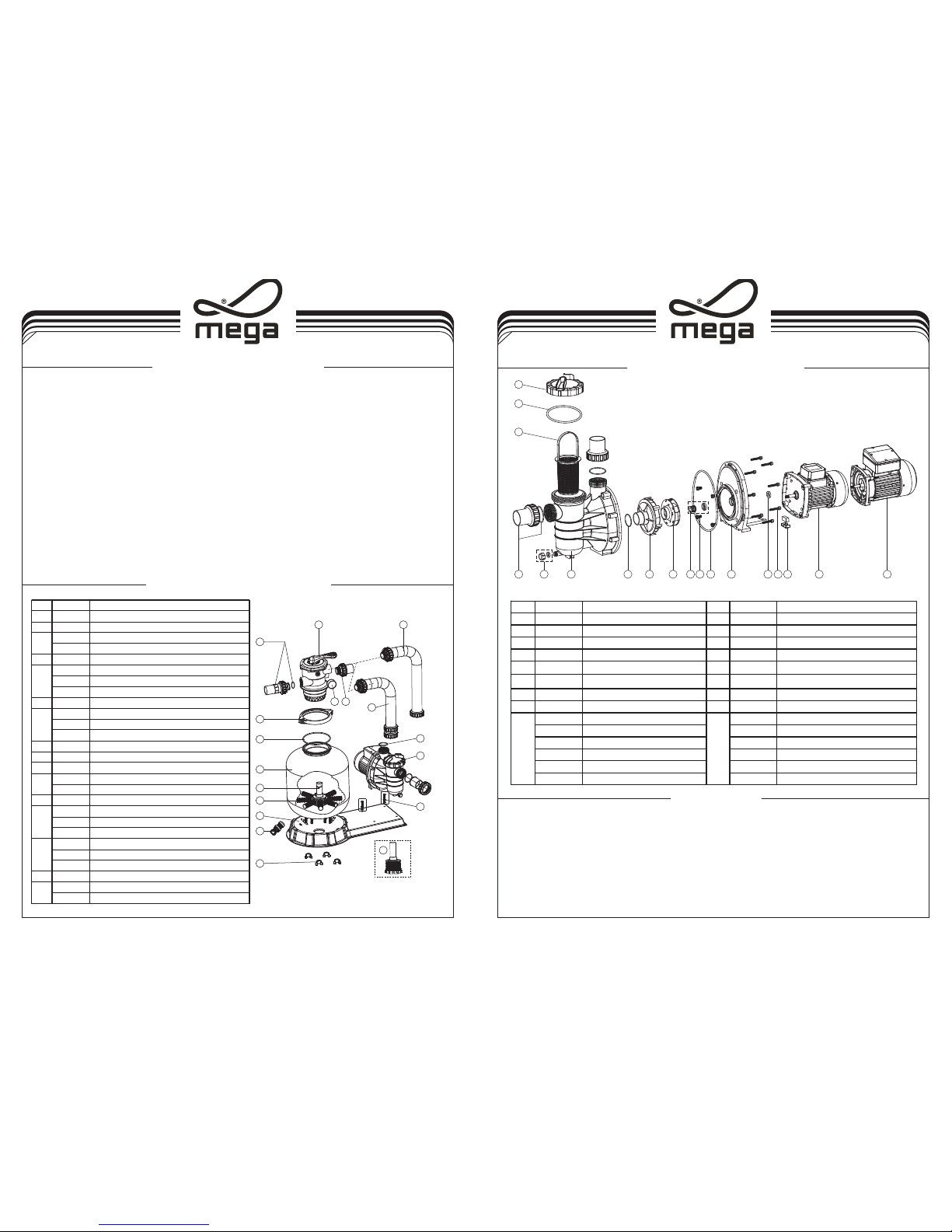
SS PUMP REPLACEMENT PARTS
4
Release all air from filter and piping system.
4
In a flooded suction system (water source higher than pump), pump will prime itself when suction
and discharge valves are opened.
4
If pump is not in a flooded suction system, unscrew and remove trap cover; fill trap and pump with
water.
4
Clean and inspect Ring; re-install on trap cover.
4
Replace trap cover on trap; turn clockwise to tighten cover.
NOTICE: Tighten trap cover by hand only. Pump should prime now. Priming time will depend on
vertical length of suction lift and horizontal length of suction piping.
PRIMING PUMP
1
2
3
5 6 4 7 8 9 11 10 12 13 1415 16 17 17
A B
FSF350-6W
FSF400-6W
FSF450-6W
9
10
11
13
12
14
15
16
8
7
6
5
43
51
2
V350
13
Item Part No. Description
1
88280105
1.5"Top Mount Valve
2 89280101 1.5" Unio n With S ight Glass, O-Ring
06011029 O il Pressure G auge With O -ring (40Psi)
01111048 Connec tor for pressure g auge
4 89280102 1.5" Unio n Set Wi th O-Ring
89032004 F SF350-6W P lastic Hos e with Nut
89032104 F SF400-6W P lastic Hos e with Nut
89032202
FSF450-6W P lastic Hos e with Nut
6 02011104 O-R ing for Pump
08030007 F SF350-6W P ump(SS033)
08030008 F SF400-6W P ump(SS050)
08030009 F SF450-6W P ump(SS075)
8 89032001 Pump A ssembly Scre w
9 01181052 Fastener f or Filter Base
10
89010107
Water Dr ain Set
01111056 F SF350-6W Co mbo Base
01111053 F SF400 - FSF45 0 Combo Base
12 01172007 V400-V45 0 Laterals (11 5mm)
89010106
V350 Lateral Assembly with Center Pipe and Lateral
89010116 V40 0 Lateral Asse mbly with Center P ipe
89010105 V45 0 Lateral Asse mbly with Center P ipe
89010115
V350 Filter tank
89010113 V40 0 Filter tank
89010112 V45 0 Filter tank
15 02011134 O-R ing for Filter Ne ck
89010119 M6* 50 Screws W ith Nut
01271010 Cla mp Lock
16
3
5
7
11
13
14
Item Part No. Description Item Part No. Description
1 01041025 Transparent Lid 10 89022403 M8*16 Screw with washer
2 02011074 O-Ring for lid 11 04015002 1/2"Mechanical seal
3 89022401 Basket with Handle 12 02011090 O-Ring for Flange
4
01021064
SS Pump Pre-filter 13
01021065
SS Pump Flange
5 89021702 1.5"union 14 03011035 M6*30 Screw
6 89022402 Drain Plug With O'ring 15 02011156 Motor Slinger for SS020;SS033
7 02011004 O-Ring for diffuser 15 02011153 Motor Slinger for SS050-SS120
8 01111014 Diffuser 16 89022404 Motor support
01311015 I mpeller SS020(230V/50 HZ) 89022109 M otor SS020(230V/50HZ)
01311016 I mpeller SS033(230V/50 HZ) 89022110 M otor SS033(230V/50HZ)
01311017 I mpeller SS050(230V/50 HZ) 89022105 M otor SS050(230V/50HZ)
01311018 I mpeller SS075(230V/50 HZ) 89022106 M otor SS075(230V/50HZ)
01311019 I mpeller SS100(230V/50 HZ) 89022107 M otor SS100(230V/50HZ)
01311014 I mpeller SS120(230V/50 HZ) 89022108 M otor SS120(230V/50HZ)
9 17
 Loading...