

Page 1
MD 9028 BDA GB 27.08.2002 9:42 Uhr Seite 1
09/02
MSN 5000 4839
®
Gecontroleerd voor het gebruik in Nederland
Tested to be used in Great Britain
Testet til brug i Danmark
0165
0682
®
DK
Medion Service Center
Meterbuen 6-12,
Bygning 8
DK-2740 Skovlunde
Hot-Line: +(45) 44 8405 42
Fax: +(45) 44 8400 41
NL
Medion Service Center
Postbus 7140
NL-5980 AC Panningen
Hot-Line: 0900 6334660
Fax: 0900 6546540
GB
Medion Electronics Ltd.
130 Faraday Park
Faraday Road
Dorcan
Swindon SN3 5JF
GB-Wiltshire
0870 7270370 • +44 (0) 1793 715699 (EIRE)
Fax 01793 715716
BETJENINGSVEJLEDNING
HANDLEIDING
OPERATING MANUAL
TRÅDLØST RADIO-OVERVÅGNINGSSYSTEM
DRAADLOOS BEWAKINGSSYSTEEM
WIRELESS RADIO MONITORING SYSTEM
MD 9028
Page 2

MD 9028 BDA GB 27.08.2002 9:42 Uhr Seite 2
CONTENTS
Controls and connections 7
Camera/Video Sender
and Video Receiver 7
Camera/Video Sender 8
Video Receiver 9
Connecting Up 10
Setting up the Power Supply 10
Setting up the Camera/Video Sender 11
Setting up the Video Receiver 12
Fine Tuning Your System 14
INTRODUCTION
Your Wireless Camera Kit consists of a Color Video Camera with
built-in 2.4 GHz Video Sender, and a Video Receiver unit which you
connect to a TV anywhere in your home (up to 100 ft. away from the
Camera). The Camera/Video Sender converts the video and audio
signals from the camera into a radio signals and transmits them
(even through walls) to the Video Receiver.
The Video Receiver converts the signals back to video and audio
signals which are fed through a cable to your TV's COAX or A/V
input jacks.
You can purchase additional cameras and power supplies so you
can have a multiple camera system. You can then set all cameras
to the same channel as the receiver and turn the cameras on and
off remotely so as to only ever have one camera turned on at a time.
There are just a few simple steps to follow to hook up your Camera
and Video Sender kit.
Page 3
MD 9028 BDA GB 27.08.2002 9:42 Uhr Seite 3
SAFETY NOTES
!
12. Grounding or Polarization - This product is equipped with a polarized alternating current line plug (a plug having one blade wider
than the other). This plug will fit into the power outlet only one way.
This is a safety feature. If you are unable to insert the plug fully
into the cutlet, try reversing the plug. If the plug should still fail to
fit, contact your electrician to replace your obsolete outlet. Do not
defeat the safety purpose of the polarized plug.
13. Power-Cord Protection - Power supply cords should be routed so
that they are not likely to be walked on or pinched by items placed
upon or against them, paying particular attention to cords at plugs,
convenience receptacles, and the point where they exit from the
product.
14. Lightning - For added protection for this product during a lightning
storm, or when it is left unattended and unused for long periods
of time, unplug it from the wall outlet and disconnect the antenna
or cable system. This will prevent damage to the product due to
lightning and power-line surges.
15. Overloading - Do not overload wall outlets, extension cords, or
integral convenience receptacles as this can result in a risk of fire
or electric shock.
16. Object and Liquid Entry - Never push objects of any kind into this
product through openings as they may touch dangerous voltage
points or short-out parts that could result in a fire or electric shock.
Never spill liquid of any kind on the product.
17. Servicing - Do not attempt to service this product yourself as
opening or removing covers may expose you to dangerous voltage
or other hazards. Refer all servicing to qualified service personnel.
18. Damage Requiring Service - Unplug this product from the wall
outlet and refer servicing to qualified service personnel under the
following conditions:
a) When the power-supply cord or plug is damaged,
b) If liquid has been spilled, or objects have fallen into the product,
c) If the product has been exposed to rain or water,
d) If the product does not operate normally by following the
operating instructions.
Adjust only those controls that are covered by the operating instructions as an improper adjustment of other controls may
result in damage and will often require extensive work by a qualified technician to restore the product to its normal operation,
e) If the product has been dropped or damaged in any way, and
f) When the product exhibits a distinct change in performance -
this indicates a need for service.
19. Heat - The product should be situated away from heat sources
such as radiators, heat registers, stoves, or other products including amplifiers) that produce heat.
SAFETY NOTES
!
1. Read Instructions - All the safety and operating instructions should be
read before the product is operated.
2. Retain Instructions - The safety and operating instructions should
be retained for future reference.
3. Heed Warnings - All warnings on the product and in the operating
instructions should be adhered to.
4. Follow Instructions - All operating and use instructions should be
followed.
5. Cleaning - Unplug this product from the wall outlet before cleaning.
Do not use liquid cleaners or aerosol cleaners. Use a damp cloth
for cleaning.
6. Attachments - Do not use attachments not recommended by the
product manufacturer as they may cause hazards.
7. Water and Moisture - Do not use this product near water - for
Example, near a bath tub, wash bowl, kitchen sink, or laundry tub,
in a wet basement, or near a swimming pool; and the like.
8. Accessories - Do not place this product on an unstable cart, stand,
tripod, bracket, or table. The product may fall, causing serious injury
to a child or adult, and serious damage to the product. Use only
with a cart, stand, tripod, bracket, or table recommended by the
manufacturer, or sold with the product. Any mounting of the product
should follow the manufacturer’s instructions, and should use a
mounting accessory recommended by the manufacturer.
9. A product and cart combination should be moved with care. Quick
stops, excessive force and uneven surfaces may cause the product
and cart combination to overturn.
10. Ventilation - Slots and openings in the cabinet are provided for
ventilation and to ensure reliable operation of the product and to
protect if from overheating, and these openings must not be
blocked or covered. The openings should never be blocked by
placing the product on a bed, sofa, rug, or other similar surface.
This product should not be placed in a built-in installation such as
a bookcase or rack unless proper ventilation is provided or the
manufacturer’s instructions have been adhered to.
11. Power Sources - This product should be operated only from the
type of power source indicated on the marking label. If you are not
sure of the type or power supply to your home, consult your product dealer or local power company. For products intended to operate from battery power, or other sources, refer to the operating
instructions.
Page 4
MD 9028 BDA GB 27.08.2002 9:42 Uhr Seite 4
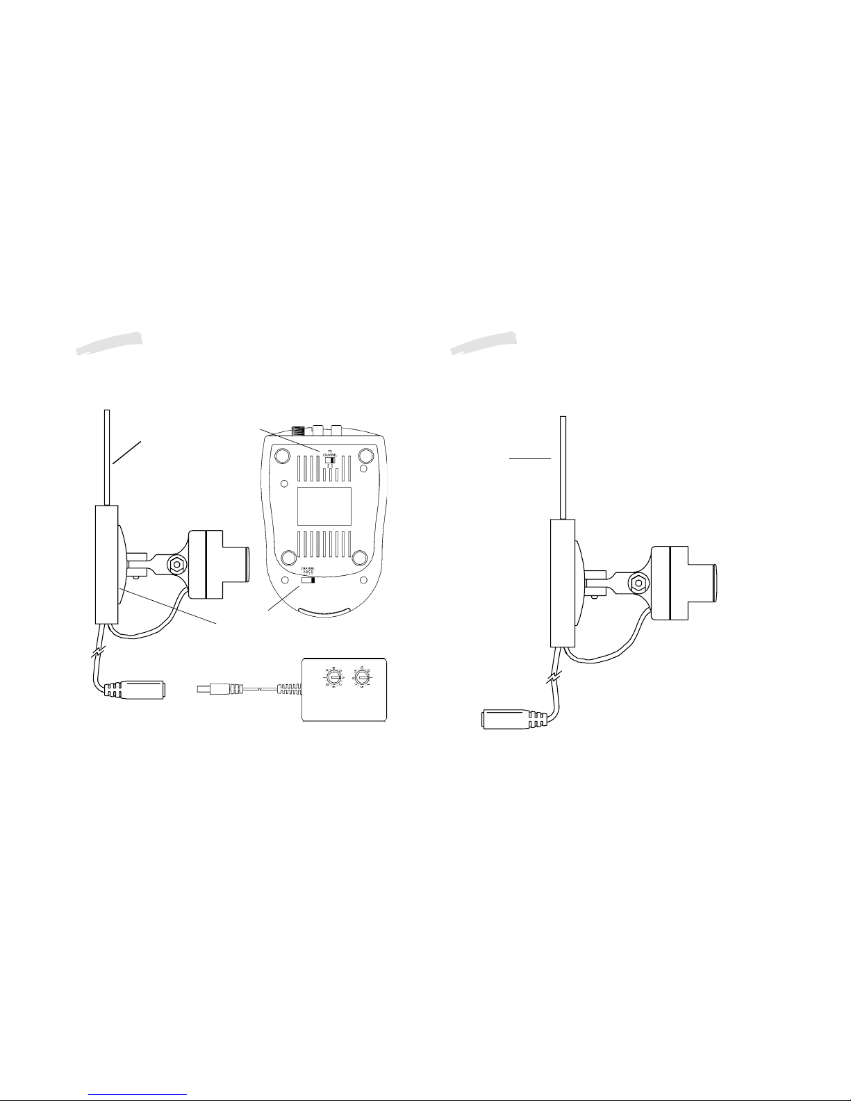
CONTROLS AND CONNECTIONS
2.4 GHz
Channel
Switch
TV
Channel
Switch
Power Supply
Socket
2.4 GHz
Video
Antenna
Camera/Video
Sender
Video Receiver
(Bottom View)
2.4 GHz Video
Antenna
Set channel switch to
match setting on
Video Receiver.
Cable adapter.
Mounting
plate
CONTROLS AND CONNECTIONS
Camera/Video Sender
Page 5

MD 9028 BDA GB 27.08.2002 9:42 Uhr Seite 5
CONTROLS AND CONNECTIONS
Video Receiver
2.4 GHz
Video
Antenna
TV Output
Connector
A/V Jacks
Power Supply
Jack
2.4 GHz Channel
Switch
(on bottom)
TV Channel
Switch
(on bottom)
ON-OFF
Switch
(on side)
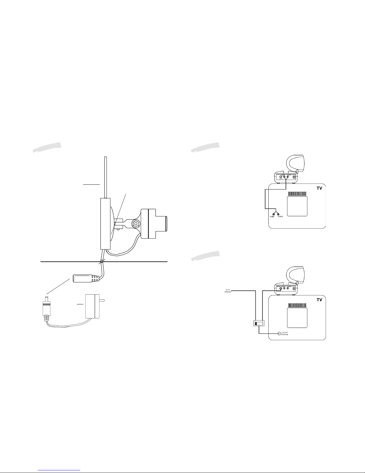
SETTING UP THE CAMERA/VIDEO SENDER, POWER SUPPL Y
Referring to the diagrams below and on the next page:
1. Attach the camera to a wall using the screws provided.
2. If you install the camera outdoors, make a small hole in your
exterior wall and pass the low voltage power jack through it.
3. Plug the power supply jack into the socket on the adapter cable
from the camera.
4. Plug the power supply into any 230 V/~50 Hz AC outlet.
5. Set the channel switch on the camera to any letter A, B, C, or D
6. Adjust the antenna if necessary to aim it in the direction of the
TV or monitor that you will view the camera on.
Page 6
MD 9028 BDA GB 27.08.2002 9:42 Uhr Seite 6
SETTING UP THE CAMERA/VIDEO SENDER, POWER SUPPL Y
2.4 GHz Video
Antenna
Plug power
supply in here.
Important:
Unplug
power supply before
unplugging power jack.
Plug into
any AC
outlet
Set channel switch to
match setting on
Video Receiver.
Outdoors
Indoors
Attach camera to a
wall, indoors or
outdoors.
Set codes
wheels.
HOOKING UP THE VIDEO RECEIVER
1. Connect a set of Audio/Video
cables to the A/V OUT jacks on the
Video Receiver. Connect the other
end to your TV (use either L or R
channel for audio).
2. Plug the Video Receiver's Power
Supply jack (the power supply
with NO code wheels) into the
Video Receiver and plug the
power supply into a
230 V/~50 Hz wall outlet.
3. Turn the Video Receiver's
power switch (on side of unit)
on.
4. Set the channel switch to the
same letter as you set on the
camera, A, B, C, or D.
5. Position the Video Receiver in a
convenient location such as on
top of the TV and orient the antenna so that the flat side points in
the direction of the room where you set up the Camera/Video
Sender.
You can use the supplied coaxial
cable to connect the TV OUT
socket on the Video Receiver to
the Antenna input on your TV.
If you already have an antenna
connected to
your TV,
you will need to use a
TV antenna splitter.
Set your TV and the
TV Channel switch on
the Video Receiver
(on bottom) to the
same channel (3 or 4).
IF YOUR TV DOES NOT HAVE A/V CONNECTORS
Page 7
MD 9028 BDA GB 27.08.2002 9:42 Uhr Seite 7
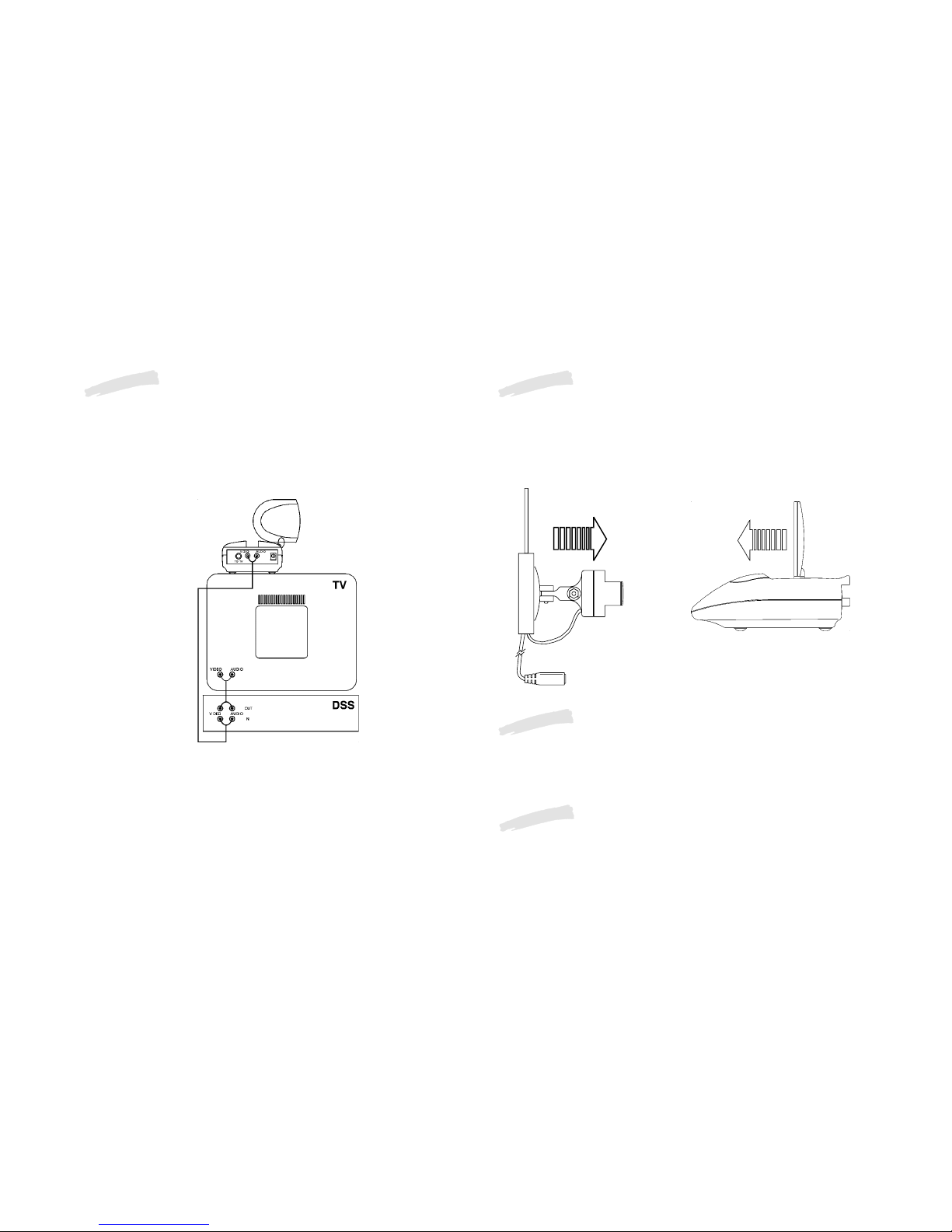
IF YOUR TV IS ALREADY HOOKED UP TO A DBS R RECEIVER
OR OTHER A/V DEVICE
If a DBS Receiver or other A/V component is connected to the TV
using A/V cables, you can connect the Video Receiver to the free
LINE IN jacks on the component. If there are no LINE IN jacks, you
will need to use a TV antenna splitter as described earlier.
FINE TUNING YOUR SYSTEM
The Wireless Video Sender usually works best with the flat faces of
the antennas on the Sender and Receiver unit facing each other (i.e.
in “Line of sight” - see diagram below). Sometimes, however,
reflections and other effects in the home may affect the signal so that
some adjustment of either the Sender or Receiver antenna may be
necessary to get the best the signal.
Check that the CHANNEL slide switch (labeled A, B, C, D) on both
units (on bottom) is set to the same letter.
If you are using coaxial TV connections from the Video Receiver,
check that the TV is tuned to the same channel as the TV Channel
switch on the bottom of the Video Receiver (3 or 4).
IF THE SIGNAL IS POOR, OR THERE IS INTERFERENCE
Try changing the channel on both units. Do this by adjusting the
CHANNEL slide switch on each unit to any position (A, B, C, or D).
Make sure both units are set to the same letter.
IF YOU ARE NOT GETTING ANY SIGNAL AT ALL
 Loading...