

Page 1

MEDIAEDGE
Technical Manual
- Configuration and Operation -
MEDIAEDGE Version 4.10
Ver.4.10, 1st Edition, February 2012
Page 2

MEDIAEDGE Technical Manual Ver4.10
LIMITED LICENSE TO USERS
Notice to the Readers
MEDIAEDGE makes no warranty of any kind with regards to this material, including, but not
limited to, the implied warranties of merchantability and fitness for a particular purpose.
MEDIAEDGE shall not be liable for errors contained herein or for incidental, consequential
damages in connection wi t h t he furnishing, performance, or use of this mater ial.
This document contains proprietary information which is protected by copyright. All rights are
reserved. No part of this document may be photocopied, reproduced, or translated into another
language without the prior written consent of MEDIAEDGE.
The information in this docu ment is subject to change without notice.
Warranty
MEDIAEDGE warrants that the enclosed product media will be free from defects for ninety (90)
days after purchase of the software. The software and any related document ation are prov ided "as
is" without warranty of any kind. MEDIAEDGE specifically does not warrant that the software will
run uninterrupted or error-free. The exclusive remedy for a defect in the product media is for the
customer to notify MEDIAEDGE of the defect in writing within the respective warranty period, to
return the product media to MEDIAEDGE and follow any other reasonable procedures which
MEDIAEDGE may establish. MEDIAEDGE’s sole obligation shall be to provide the customer with
a functioning copy of the product media within a reasonable time after receiving notification of the
defect or to refund the purchase price and terminate this license agreement, a choice to be made
by MEDIAEDGE. The foregoing warranty does not apply if customer mishandles, alters,
improperly uses or stores t he pr oduct me dia.
MEDIAEDGE has made the best efforts in generating this technical manual as accurate as
possible at the time of its publication. MEDIAEDGE cannot assume, however, any responsibility
for any inaccuracies that may be contained in the manual. In no event will MEDIAEDGE be li able
for direct, indirect, special, incidental, or consequential damages resulting from any defect or
omission in the manual even i f advised of the possibility of such damages.
MEDIAEDGE IS NOT RESPONSIBLE FOR ANY LOST PROFITS, LOST SAVINGS, OR OTHER
INCIDENTAL OR CONSEQUENCIAL DAMAGES ARISING OUT OF THE USE OF, OR INABILITY
TO USE, THIS P RO D U CT. THIS IN CL UDE S D AM AG E T O PRO P ERTY AN D, T O THE EX TE NT
PERMITTED BY LAW, DAMAGES FOR PERSONAL INJURY. THIS WARRANTY IS IN LIEU OF
ALL OTHER WARRANTIES OF MERCHANTABILITY AND FITNESS FOR A PARTICULAR
PURPOSE.
Notes
1. Microsoft and Windows are registered trademarks of Microsoft Corporation in the US. Other
product names and related items are trademarks or registered trademarks of their respective
companies.
2
Page 3

MEDIAEDGE Technical Manual Ver4.10
The information in this manual is described accordin g to the following MEDIAEDGE products unless
otherwise noted.
MEDIAEDGE-SVS4
MEDIAEDGE-SWT4
MEDIAEDGE-DAS4
MEDIAEDGE-STB4
MEDIAEDGE-STB4H
MEDIAEDGE-LEB4
MEDIAEDGE-LEB60
MEDIAEDGE-LSB
HDMA-4100
3
Page 4
MEDIAEDGE Technical Manual Ver4.10
4
I.
····················································· 11
························ 12
································································· 15
II.
···························· 23
- Table of Contents -
MEDIAEDGE System Overview ············· 10
I-1. What Is MEDIAEDGE?
I-2. MEDIAEDGE4 Component Devices
■ I-2-1. MEDIAEDGE-SVS4 ····································································· 12
■ I-2-2. MEDIAEDGE-STB4 ····································································· 12
■ I-2-3. MEDIAEDGE-STB4H ··································································· 12
■ I-2-4. HDMA-4100 ··············································································· 13
■ I-2-5. MEDIAEDGE-SWT4 ···································································· 13
■ I-2-6. MEDIAEDGE-LSB ······································································· 14
■ I-2-7. MEDIAEDGE-LEB4 ····································································· 14
■ I-2-8. MEDIAEDGE-LEB60 ··································································· 14
I-3. Server functions
■ I-3-1. MEDIAEDGE S erver Configuration ················································· 15
■ I-3-2. S t ream Serv er ············································································ 16
■ I-3-3. Database Server ········································································· 17
■ I-3-4. DHCP Serv er ············································································· 18
■ I-3-5. DNS Server ··············································································· 19
■ I-3-6. Web Server ················································································ 19
■ I-3-7. Time Server ··············································································· 20
■ I-3-8. SWT Authent ication Server ··························································· 21
MEDIAEDGE System Performance ········ 22
II-1. Delivery Performance of Servers
■ II-1-1. Network Interface (NIC) ······························································· 24
■ II-1-2. Disk ························································································· 25
■ II-1-3. CPU ························································································ 27
■ II-1-4. Memory ···················································································· 27
■ II-1-5. Other Factors ············································································ 27
■ II-1-6. Checking the Load on the Server ··················································· 28
Page 5
MEDIAEDGE Technical Manual Ver4.10
5
········ 29
····················· 34
······················································ 35
·············································· 36
III.
··········································· 38
·································· 39
································ 40
II-2. Validation Results of Server Performance
■ II-2-1. Express5800 110Gc (SATA-HDD model) ········································· 29
■ II-2-2. Express5800 110Ri-1 (SAS-Raid model) ········································· 30
■ II-2-3. Express5800 120R i-2 (SAS-Raid model)········································· 31
■ II-2-4. Express5800 120R i-2 (SATA-Raid model) ······································· 32
■ II-2-5. PowerEdge 2950 III (SATA-Raid model) ·········································· 33
II-3. Performance of the Network Switch
■ II-3-1. Key points of the network switch ···················································· 34
■ II-3-2. Port Speed ················································································ 34
■ II-3-3. Delivery Performa nce of Unicast ··················································· 34
■ II-3-4. Delivery Performa nce of Multicast ·················································· 34
II-4. Reception by Clients
■ II-4-1. Reception on MEDIAEDGE-STB4/STB4H/HDMA-4100 ····················· 35
■ II-4-2. Reception by MEDIAEDGE-SWT4 ················································· 35
II-5. Delivery on the Live Unit
■ II-5-1. Understanding the Delivery ·························································· 36
■ II-5-2. Understanding the Relay ······························································ 36
■ II-5-3. Multicast Pac kets ······································································· 36
MEDIAEDGE System Design ··············· 37
III-1. System Design Guideline
■ III-1-1. Required items for system require ment s ········································ 38
■ III-1-2. Setting factors decided from the required spec ific ation s ···················· 38
III-2. Capacity of the Content Drive
III-3. Data delivered on the Network
■ III-3-1. Performance and li m itations of MEDIAEDGE system
regarding streaming data ···························································· 40
■ III-3-2. Using only "unicast delivery" ························································ 42
■ III-3-3. Using only "multicast delivery" ······················································ 43
■ III-3-4. Using "unicast delivery" and "multicast delivery" simultane ously ·········· 44
■ III-3-5. Using ME DIAEDGE-LSB/LEB4/LEB60 ·········································· 44
Page 6
MEDIAEDGE Technical Manual Ver4.10
6
·························· 49
······································ 54
IV.
····················································· 56
······················································ 61
··············································································· 63
······································································ 65
■ III-3-6. Improving Multicast De liv er y Performances over the Network
Using IGMP Snooping ································································ 46
■ III-3-7. Calculation of the st r eam data ······················································ 47
III-4. Improving System Performances
■ III-4-1. Improving Network Perfor mances ················································· 49
■ III-4-2. Server Load Dispersion ······························································ 49
■ III-4-3. TS Packet s ··············································································· 51
■ III-4-4. Improving Perfor m ance with Network Switch Configuration ················ 53
■ III-4-5. Bandwidth control functions of MEDIAEDGE-LEB4 ·························· 53
III-5. Tuning Server Performance
■ III-5-1. Improving Perfor m ance with NIC Configuration································ 54
■ III-5-2. Improving Performance with Disk Conf igurat ion ······························· 54
■ III-5-3. Setting Process Priorit y······························································· 54
MEDIAEDGE System Co nfiguration ····· 55
IV-1. Server configuration
■ IV-1-1. Single Server/Single Segment Configuration ··································· 56
■ IV-1-2. Multi Server ·············································································· 57
■ IV-1-3. Multi-segment ··········································································· 58
■ IV-1-4. How to change the computer name of the ser ver
where MEDIAEDGE-SVS4 is inst alled ··········································· 60
IV-2. Client Configuration
■ IV-2-1. Mixed Configuration with MEDIAEDG E-STB4/SWT4 ························ 61
■ IV-2-2. Configuration for MEDIAEDGE-DAS4 ············································ 62
IV-3. Multicast
■ IV-3-1. Controlling Multicast Streams by IGMP ·········································· 63
IV-4. Live Delivery
■ IV-4-1. Configuration for direct delivery fro m ME DI AEDGE-LSB/LEB4/LEB60
to clients ·················································································· 65
■ IV-4-2. Configuration for relay delivery by ser ver ········································ 66
■ IV-4-3. Configuration where MEDIAEDGE-LSB/LEB4/LEB60 and clients
are divided into segments ··························································· 67
■ IV-4-4. MEDIAEDGE-LSB/LEB4/LEB60 multicast delivery conf iguration ········· 69
Page 7
MEDIAEDGE Technical Manual Ver4.10
7
··········································································· 71
············································································ 72
·························································································· 75
V.
······················································································ 80
························································································ 83
IV-5. Using NAS
■ IV-5-1. Configuration with NAS······························································· 71
IV-6. Using VPN
■ IV-6-1. VPN connection between server and clients (Remote delivery) ··········· 72
■ IV-6-2. VPN connection of MEDIAEDGE-LSB/LEB4/LEB60,
Server and Clients ( Re m ote) ······················································· 73
■ IV-6-3. Connection via NAT/NAPT ·························································· 74
IV-7. IPv6
■ IV-7-1. Configuration without an IPv6 router ·············································· 75
■ IV-7-2. Configuration with an IPv6 router ·················································· 76
■ IV-7-3. Controlling multicast stream by ML Dv 2 ·········································· 77
Settings and Operation Controls ············ 79
V-1. Server
■ V-1-1. Setting the exent log ··································································· 80
■ V-1-2. Web server security ···································································· 80
■ V-1-3. Synchronizing the Clock ······························································ 82
V-2. Client
■ V-2-1. Changing the remote control ID ····················································· 83
■ V-2-2. Notes on Setting Up Using Internet Explorer ···································· 84
■ V-2-3. Updating firmware ······································································ 85
■ V-2-4. Managing clients with the Server console ········································ 88
■ V-2-5. Redirect ··················································································· 89
■ V-2-6. MEDIAEDGE-STB4 menu ··························································· 90
■ V-2-7. Remote Serial ··········································································· 97
■ V-2-8. Setting Wake On LAN ································································· 97
■ V-2-9. Setting the output format······························································ 98
■ V-2-10. Reviewing the log ····································································· 99
■ V-2-11. Downloading the log file ····························································· 100
■ V-2-12. Using MEDIAE DGE-DAS4 on MEDIAEDGE-SWT4 ························· 101
Page 8

MEDIAEDGE Technical Manual Ver4.10
8
··············································································· 102
············································································· 105
······················································· 114
··················································· 117
···················································································· 120
V-3. Live unit
■ V-3-1. URL························································································· 102
■ V-3-2. Direct delivery to clients ······························································· 102
■ V-3-3. Updating firmware ······································································ 103
■ V-3-4. Reviewing the log ······································································· 103
■ V-3-5. Remote Serial ··········································································· 104
■ V-3-6. Wake On LAN ··········································································· 104
V-4. Database
■ V-4-1. Using Microsoft SQL Server Management St udio Express (SSMSE) ···· 105
■ V-4-2. Limiting the memory usage ·························································· 105
■ V-4-3. Security settings (remote access, sa password) ······························· 107
■ V-4-4. Backup and restoration································································ 109
■ V-4-5. Compressing data on the SQL Server, and r es t r uct ur ing index ············ 111
■ V-4-6. Operating database with MS-Access ·············································· 113
V-5. Managing contents
■ V-5-1. Registering MPEG file content s ····················································· 114
■ V-5-2. Registering live contents ······························································ 115
■ V-5-3. Live record ················································································ 115
■ V-5-4. Registering relay contents ···························································· 115
■ V-5-5. Relay record ············································································· 116
V-6. Managing schedules
■ V-6-1. Setting schedules ······································································· 117
■ V-6-2. Multicast schedules ···································································· 118
■ V-6-3. Unicast schedules ······································································ 119
V-7. SNMP
■ V-7-1. SNMP support ··········································································· 120
■ V-7-2. SNMP settings on MEDIAEDGE-STB4/STB4H/HDMA-4100/
MEDIAEDGE-LSB/LEB4 ····························································· 120
■ V-7-3. SNMP settings on server ····························································· 120
■ V-7-4. MIB ························································································· 121
Page 9

MEDIAEDGE Technical Manual Ver4.10
9
····· 122
···················································· 124
·················································································· 130
V-8. Using Vendor Specific Information Editor
■ V-8-1. Applying parameters ··································································· 122
■ V-8-2. Reloading ················································································· 122
■ V-8-3. Opening DHCP management console ············································ 122
■ V-8-4. Copying or moving the environment to another Server ······················· 122
■ V-8-5. Applying different settings on a unique unit ······································ 123
V-9. Sample Applications
V-10. Notes
■ V-10-1. Notes on Operation over Long Periods of Time ······························· 130
■ V-10-2. Notes on remote access of the ActiveX control ······························· 130
■ V-10-3. Using ActiveX of the server (MeSrv . Me Srv Ctrl) remotely (DCOM) ······· 130
Page 10

MEDIAEDGE Technical Manual Ver4.10
10
I.
MEDIAEDGE System Overview
Page 11

MEDIAEDGE Technical Manual Ver4.10
11
I-1. What Is MEDIAEDGE?
MEDIAEDGE is a content delivery system that delivers video content via the network.
MEDIAEDGE allows clients to play back v ideo that is sent fro m the serv er, and allows the server t o
record live video as a file.
The video content that MEDIAEDGE can handle includes the following:
・ File content
MPEG file content stored i n t he s erver. MPEG2 (SD/HD) and H.264 are available.
・ Live content
Video content input in t he live device connected to the server.
Video content sent from a live unit via network.
MEDIAEDGE offers three delivery methods: VOD d elivery, Scheduled d elivery, and Relay delivery.
・ VOD (Video on Demand) deliver y
Video data is se lect ed and played from the menu.
Data delivered to the network is in unicast.
・ Scheduled delivery
Video data is delivered according to predefined schedules. On clients, you can choose a
channel to watch to play bac k the video being delivered at that time.
Delivery is multicast or un i cast.
・ Relay delivery
Live video delivered from liv e units can be received and relayed it to ot her c l ient.
Delivery is multicast or un i cast.
MEDIAEDGE offers four live recording functions:
・ Manual recording of live contents
・ Scheduled recording o f l iv e c ont ents
・ Manual recording of relay contents
・ Scheduled recording o f relay contents
Recorded data are available to deliver once they are registered as file co nt ents.
On MEDIAEDGE version 4. 1, the following functions are also available.
・ MEDIAEDGE-STB4/STB4H/HDMA-4100/MEDIAEDGE-SWT4-DS functionality expansion
(all of the following features are available on the DCM, Display Content Manager.)
Display of still image
Audio playback
Flash playback
Display of tickers
SMIL contents support (support s multiple contents and layouts).
HTML
QuickTime playback (MEDIAEDGE-SWT4-DS only)
Even when the DCM is not used, these features are available by directly specifying the URI with
the client control (Redirect control) from the Server console.
Page 12

MEDIAEDGE Technical Manual Ver4.10
12
■
■
■
■
■
■
■
■
■
■
■
■
■
■
■
■
■
■
■
■
■
■
■
■
■
■
I-2. MEDIAEDGE4 Component De vices
MEDIAEDGE consists of the following devices and software.
・ Server
Server that delivers data to clients, and includes Delivery Server and DB Server. Must be
configured in Windows Server .
・ Playback client
Client that receives and play s back video se nt from a serv er. Video data sent fr om a server
is received via the network. Dat a is not stored on the client; rather, it is played back in real
time.
・ Live unit
Streaming unit that is connected to a camera and delivers live video. It has video/audio
input and a network interface, which allows to deliver a live content. Video fr om a li ve uni t
can be either played directly on the playback client or relayed on a server before being
played on the client.
MEDIAEDGE Server software
I-2-1. MEDIAEDGE-SVS4
Delivers MPEG2, or H.264 stream.
Provides VOD (video on demand) and scheduled delivery.
Records and delivers live video, utilizing live units or live devices.
Supports multicast and unicast deliveries.
Provides a Web appl ication for configuring contents and schedules.
Playback client
I-2-2. MEDIAEDGE-STB4
Supports MPEG2 and H.264 reception and playback.
Provides a customizable menu screen.
Provides an HDMI port and component ports that allow playback in high resolution.
Provides a gigabit LA N po r t .
Supports a remote c ont r ol ler (optional).
Provides a built-in Web server for modifying variou s set t ings via a browser.
Provides playback control by means of the redirect function.
Supports time adjust by NTP.
Supports SNMP.
I-2-3. MEDIAEDGE-STB4H
SupportsMPEG2 and H.264 reception and playback.
Provides a customizable menu screen.
Provides an HDMI port t hat allows playback in high resolution.
Provides a gigabit LA N po r t .
Supports a remote c ont r ol ler (optional).
Provides a built-in Web server for modifying various settings via a browser.
Provides playback control by means of the redirect function.
Supports time adjust by NTP.
Supports SNMP.
Page 13

MEDIAEDGE Technical Manual Ver4.10
13
■
■
■
■
■
■
■
■
■
■
■
■
■
■
■
■
■
■
■
■
■
■
■
■
I-2-4. HDMA-4100
Supports MPEG2 a nd H.2 64 playback.
Equipped with 2.5 inch HDD or SDD.
Supports schedule d pl ayback with the date and time specified. (Schedul ed playback mode)
Provides serial control functions with DVD/LD-c ompatible commands. (Serial control mode)
Provides a customizable menu screen. (Menu mode)
Maintains contents and schedules via network.
Supports playbac k from the internal HDD (or SDD).
Supports playback from external memory devices (HDD, USB memory) connected with the
USB.
Supports power management by the UPS connected to the USB. *
Provides a built-in Web server, which allows modifyi ng various settings via a browser.
Provides playback control by the redirect function.
Supports time adjus t by NTP.
Supports SNMP.
* OMRON uninterruptible power supply sy st em (BX 35F, BX50F) is supported.
BX35F and BX50F are trademarks or registered trademarks of OMRON Corporation.
I-2-5. MEDIAEDGE-SWT4
The MEDIAEDGE-S WT4 contains the following two modules.
- MEDIAEDGE-SWT4-DS:
Client application that suppor ts layout playback
- MEDIAEDGE-SWT4 (ActiveX Control):
ActiveX Control for stream ing v ideo playback
Supports MPEG2 and H.264 reception and playback.
Displays video on the desktop.
Supports streaming playback sent from the MEDIAEDGE-SVS4.
Supports displaying layout contents on the computer.
Supports displaying movie, still picture, HTML file, mov file, and/or ticker as co ntent.
Supports playbac k of the file contents on the local storage (control led by Schedule.txt).
Provides two authentication methods: dongle and network.
Provides playback control by the redirect function.
Page 14

MEDIAEDGE Technical Manual Ver4.10
14
■
■
■
■
■
■
■
■
■
■
■
■
■
■
■
■
■
■
■
■
■
■
■
■
■
Live unit
I-2-6. MEDIAEDGE-LSB
Strea m ing d elivery of HD video (MPEG2-HD) input through IEEE1394.
Multicast and unicast can be s w itc hed.
Delivers contents automatically to a specific multicast gr oup at startup.
Provides a built-in Web server for modifying various settings via a browser.
Provides serial port for p assthrough.
Supports SNMP.
I-2-7. MEDIAEDGE-LEB4
Encodes video signal to H.264 in rea l t i me, and performs streaming delivery.
Enables switching between multicast and unicast.
Delivers cont ents automatically at startup.
Provides on-demand delivery by request from the MEDIAEDGE-STB4/STB4H/HDMA-4100/
MEDIAEDGE-SWT4 or the relay servers.
Provides serial port s for passthrough.
Provides a built-in Web server for modifying various settings via a browser.
Can display date/time and t it les on str eaming video.
Supports SNMP.
I-2-8. MEDIAEDGE-LEB60
Encodes analog video signal to MPEG1 or MPEG2 in real time, and performs streaming
delivery.
Enables switching between multicast and unicast.
Delivers cont ents automatically to a specific multic ast group at startup.
Provides on-demand delivery by request from the MEDIAEDGE-STB4/STB4H/HDMA-4100/
MEDIAEDGE-SWT4 or the relay servers.
Provides serial port s for passthrough.
Provides a built-in Web server for modifying various settings via a browser.
Provides a frame-skip function, which prevents video quality from deteriorating.
Can display date/time and t it les on str eaming video.
Page 15
MEDIAEDGE Technical Manual Ver4.10
15
■
Client
RTSP
RTP
SQL
SQL
HTTP
SQL
HTTP
MeSrv
SQL server
Web server
DNS
DHCP
SWT
Time
NTP
Web browser
I-3. Server function s
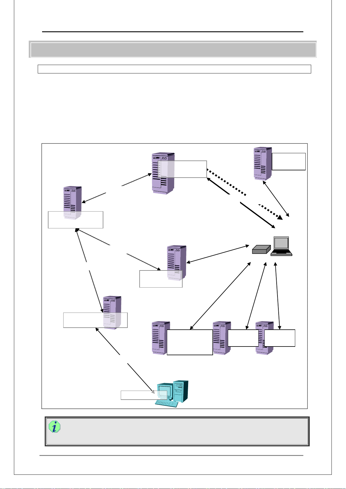
I-3-1. MEDIAEDGE Server Configuration
The MEDIAEDGE Server consists of the following components (which can but need not be
installed on a single server):
・ Stream server (required)
・ Database server (required)
・ DHCP server
・ DNS server
・ Web server (required)
・ Time server (NTP server)
・ SWT authenticat i on ser ver
server
Stream server
Database server
Web server
Server console
Menu server
authentication
server
Control computer
(Web browser)
server
server
Controlling, surveying server
Managing clients and contents
Multiple stream servers can be set up.
Depending on the load, the system can be configured on a single server or on multiple
servers.
Page 16
MEDIAEDGE Technical Manual Ver4.10
16
■
I-3-2. Stream Server
The stream server is a software package that receives requests from clients and exports MPEG
streams. It functions as a ser vice (MeSrv) on the server.
○Stream Server Functions and Roles
I RTSP server
Exchanges RTSP messages with clients. Client s send content or channel requests and
the server provides inform at ion necessary for receiving stream.
II RTP server
Delivers VOD contents (as requested by RTSP) and scheduled playback contents to
the channels following the defined schedule.
The delivery protocol is RTP.
III Storing content files
Normally, content files are stored in the local storage on the stream server. Files that
are created with a Live Record or Relay Record are also saved here.
IV Database client
Inquires of the database for the whereabouts of the MPEG data (information on MPEG
files or live devices) to be exported with R TSP URL as the key.
It also checks in with the database periodically to confirm the schedule registered on
the database.
V Scheduler
Causes delivery to be started/stopped according to the registered schedule.
VI RTSP redir ect cl i ent
Issues RTSP redirect commands by calling up the necessary program interface that
has been disclosed.
VII Relay delivery of live stream
Receives the stream sent from the MEDIAEDGE-LSB/LEB4/LEB60 and relays it to
clients.
The stream server can be said t o be a client of the MEDIAEDGE-LSB/LEB4/LEB60.
To activate stream-server s ervice, you must connect the USB dongle to the ser ver.
Software Installation
Set the MEDIAEDGE-SVS4 installation DVD, check the components of the stream server,
and perform the installati on. I f the DB server is not inst alled at the sa me time as the st ream
server, you are prompted to specify the DB serv er w hen you install the stream server.
Page 17
MEDIAEDGE Technical Manual Ver4.10
17
■
I-3-3. Database Server
The MEDIAEDGE system utilizes the database to use the Web server (which provides client
content or acts as Server console) and the streaming server. Mi crosoft SQL Server 2005, and
Microsoft SQL Server 2005 Express Edition are supported. Decentralization of the servers is
available along with online content and schedule update using the databa s e.
Data mainly stored in the database:
1 All information on video contents (excluding MPEG files)
2 All information on the schedu le
3 Information on the clients
4 Information on the relay c ont ents
Additional information can be added by the users. For example, client contents can be
controlled based on added information, i.e. charges and viewers.
For details on the database, see the "MEDIAEDGE Technical Manual - Technical
References -".
Software Installation
Set the MEDIAEDGE-SVS4 installation DVD, check the components of the database
server, and perform the installation. During installation, you can install SQL Server 2005
Express Edition. To use versions or editions of DBMS other than SQL Server 2005
Express Edition, you must have the other DBMS versions or editions inst al led in advance.
Page 18
MEDIAEDGE Technical Manual Ver4.10
18
■
I-3-4. DHCP Server
DHCP (Dynamic Host Configuration Protocol) server is placed in the network mainly to automate
assignments of IP addresses. By using the DHCP server, IP addresses do not need to be
assigned to each client and net work parameters can be distributed a ut omatically .
DHCP server functions are standard features in Windows Server 2008/Windows Server 2008
R2/Windows Server 2003. Not installed by default, they can be installed by selecting the DHCP
server service during or a fter installation of Windows Server.
DHCP server ca n be additionally installed in one MEDIAEDGE Server , but in a large-scale system
(multi-server confi gur ation), DHCP server should be included on a different server from those with
stream servers.
○DHCP Server in the MEDIAEDGE System
Automatic IP Address Assignment and Centr alized Control
IP address for MEDIAEDGE-STB4/STB4H/HDMA-4100 can either be set up as a fixed IP
address or as a DHCP client. For DHCP client, the DHCP server defines the scopes and the
IP address is assigned by setting up an address pool. MEDIAEDGE-STB4/STB4H/HDMA4100 will send requests for assignment of IP address to the DHCP server when it is turned
ON or when the system is reset .
For MEDIAEDGE-SWT4, DHCP can be setup to be used in Windows network settings
(default). IP address assigned by the DHCP server is not necessary the same each time, but
a lease period can be assi gned t o t he IP address during which other cl ients will not be able to
use it.
Assignment of Reserved IP Address
When IP addresses are a utomatical ly assigned by the DHCP server, it may be difficult to keep
track of these assignments. To solve this problem, a list of MAC addresses and IP addresses
can be used, which is created by the Windows Server administrative tool. Reservation
function can be used whe n you want to pre-assign IP addresses to the cl ie nts.
MAC address is needed to make reservations. MEDIAEDGE-STB4/STB4H/HDMA-4100
address is written on the bottom of the main unit. Reservations can easily be made using
the "V ender-specific Information Editor".
Network Parameter Notif icat ions
DHCP server not only automatically assigns IP addresses to the clients, but also notifies the
IP address of the DNS server and domain name simultaneously. When specifying client
content menu or vide o co ntent U RL using server names, bot h DNS ser v er a nd do m ain na mes
will be needed, therefore setting up these network parameters at the same time is
recommended. Rout er ( default gateway) IP addresses can also b e setup if needed.
Software Installation
Add the server as a Windows component. See the “MEDIAEDGE-SVS4 User Guide” for
configuration details.
Page 19

MEDIAEDGE Technical Manual Ver4.10
19
■
■
I-3-5. DNS Server
Main function of the DNS server is to provide the means for name resolution. One or more DNS
servers can be set up in a networ k. By using DNS s e rv ers, users w ill be free d fr om the pr ep aration
of name & IP address list for each c li ent and updating these lists will be easier.
DNS server functions are standard features in Windows Server 2008/Windows Server 2008
R2/Windows Server 2003. Not installed by default, they can be installed by selecting the DNS
server service during or a fter installation of Windows Server.
DNS server can be installed in one MEDIAEDGE Server, but in a large-scale system (multi-server
configuration), DNS serv er should be in cluded on a dif fere nt server from those with stream servers .
Host name/IP address of MEDIAEDGE Server should be defined by the DNS server.
Functions of the DNS serv er in t he MEDIAEDGE system:
• Name resolution for HTTP URL
• Name resolution for RTSP URL
In a system not using a DNS serv er, the IP addresses must be used as the server names for HTTP
or RTS P UR Ls . Alternatively on MEDIAEDGE-SVS4/SWT4, the HOSTS file that contains entries
of server name & IP address can be used.
Software Installation
Add the server as a Windows component. See the “MEDIAEDGE-SVS4 User Guide” for
configuration details.
I-3-6. Web Server
MEDIAEDGE system uses Web server – Web browser combination as user interface for client
contents. This is also true for Server console.
Functions of the Web serv er:
1 Provides clients with the menu
2 Provides a Server console page for controlling the servers
As A SP (Active Server Pages) is used for the standard menu and the Server console, IIS (Internet
Information Services Ver.6.0 for Windows Server 2003, and Internet Information Services Ver. 7.0
for Windows Server 2008) is required for the Web server.
In Windows Server 2008/Windows Server 2008 R2/Windows Server 2003, IIS is a standard
function but is not installed by default. Install the Web server, following the “MEDIAEDGE-SVS4
User Guide”, BEFORE installing MEDIAEDGE-SVS4.
MEDIAEDGE-SWT4 uses the Windows Internet Explorer for the browser. HTML files can be
placed in the local disk of the computer also.
Web server is requir ed for displaying the menu.
Depending on the combinations of Web server and browser, following features will be av ail able:
1. Easy Customiz at ion of Client Contents
A menu sy st em is a must as the user interface for ma king sel ecti ons from v ari ous conte nt s
in VOD or scheduled playback. Combination of Web server and browser allows easy
configuration of the menu system.
MEDIAEDGE-SWT4 supports various plug-ins and can implement animations.
2. Easy Generation of Client Contents Li nked to the Database
Updates on the video contents will be reflected in the menu for clients.
Menu linked to the video contents can be created by preparing scripts on the Web server,
dynamically generating an HTML document referring to the database, and sending it to
clients. It is also possible to implement search or narrowing down functions in the menu or
to change contents by clients, viewers, or timeframes.
Page 20

MEDIAEDGE Technical Manual Ver4.10
20
■
3. Using Server console from a Remote computer
Important information is stored in the server, therefore it is a must that they are securely
administered for safe oper ations. O n the other hand, when secur ity get s tighter, its usability
will decrease. That is why users are looking for remote control and monitoring servers or
managing clients and contents from a non-server computer via network. Remote
maintenance will be avail able with the combination of Web server and browser.
Use of remote computer as console is also recommended to lighten the burden on the
server. Windows uses graphic driver and API that operates in kernel mode on GUI,
therefore when Server console is executed on the server, its performance declin es. This is
especially true when Server console is executed on the stream server, posing problems in
exporting streams.
4. Easy Customization of Server console Contents
To make full use of the server functions, a Server console allowi ng usage of al l functi ons
has been prepared for MEDIAEDGE.
This Server console can be customiz ed by the users.
Ex)
Prohibit usage of basic system settings function of the Server console for the
operator.
Add standardized editing funct ions for a more efficient shuf fling of contents.
Software Installation
Add IIS as a Windows component. See the “MEDIAEDGE-SVS4 User Guide” for
configuration details.
Then add the Server console and the Sample menu from the "MEDIAEDGE-SVS4
Installation DVD".
I-3-7. Time Server
MEDIAEDGE-STB4/STB4H/HDMA-4100/MEDIAEDGE-LSB/LEB4 support time acquisition with
NTP.
When the time is specified, the time of the log is precisely recorded.
For details on how to use the Windows Server 2008/W indows Server 2008 R2/W indows Server
2003 as an NTP server, see "■ V-1-3 Synchronizing the Clock."
The following methods are available to adjust the time of the NTP server :
・ To acquire time from a time-c orr ec t i on unit
Device utilizing GPS
Device utilizing long-wave
Device utilizing FM broadcast
Device utilizing telephone line (Telephone JJY)
・ To acquire time from the NT P server that is connected to the Internet
Aside from the methods a bove, you can adju st time by directly referenc ing the NT P ser ver un it that
has the time-correction function (GPS, etc) and the NTP server functions from MEDIAEDGESTB4/STB4H/HDMA-4100 units.
Software Installation
On Windows Server 2008/Windows Server 2008 R2/Windows Server 2003, modify the
configuration by changing the Windows Time service registry. For details, see "■ V-1-3
Synchronizing the Clock."
Page 21
MEDIAEDGE Technical Manual Ver4.10
21
■
Dongle
Client PC
Server
Dongle
MEDIAEDGE-SWT4
Dongle
MEDIAEDGE-SVS4
MEDIAEDGE-DAS4
MEDIAEDGE-SWT4
Dongle
I-3-8. SWT Authentication Server
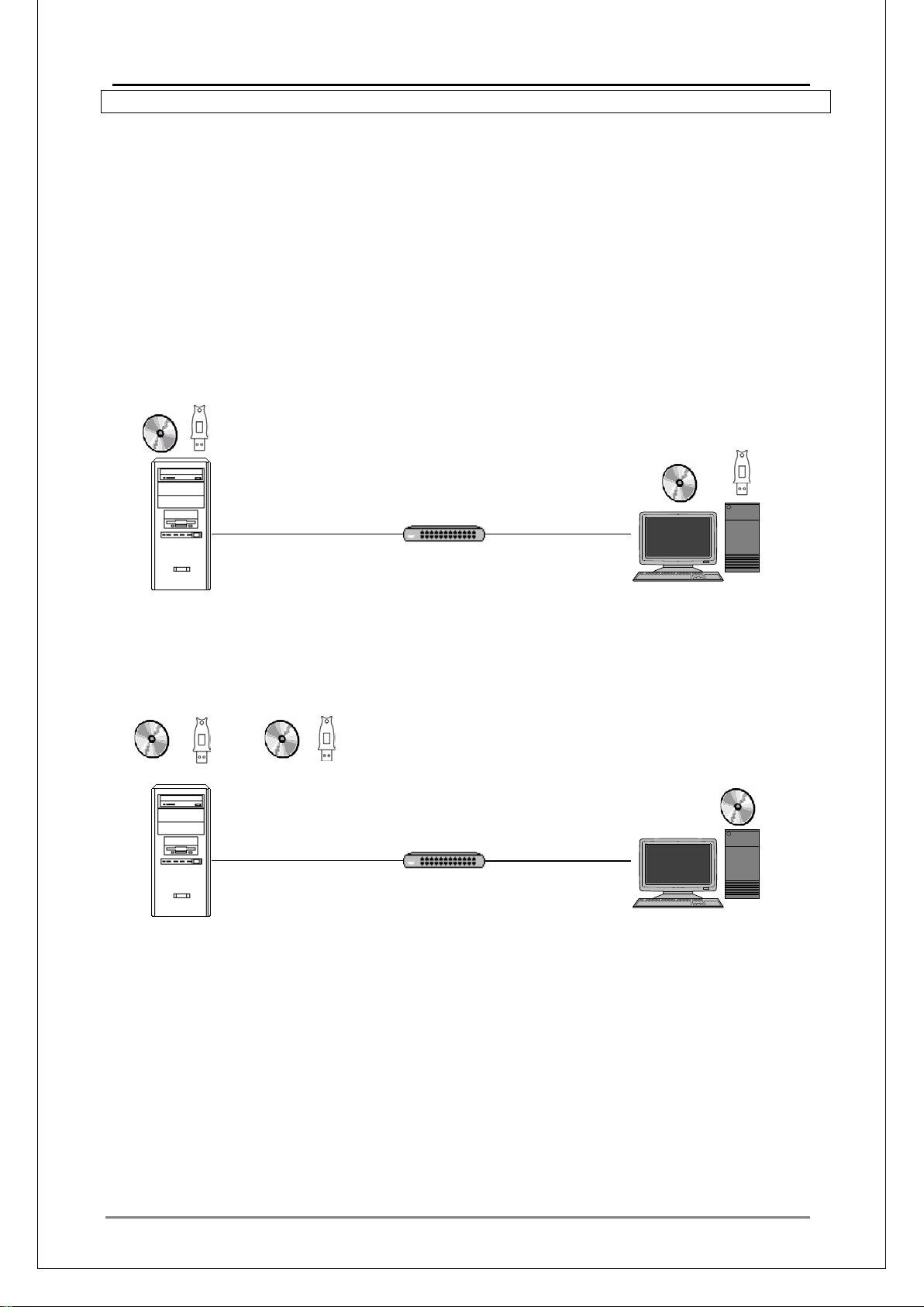
There are two authenticati on m et hods for license management of the MEDIAEDGE-SWT4.
1 MEDIAEDGE-SWT4 (Dongle authentication)
Authenticated by a dongle attached to a client computer.
2 MEDIAEDGE-SWT4 (Server authentication)
Authenticated on the netw ork by the aut henticati on serv er (MEDIAEDGE-DAS4) where
a dongle is attached. I n t hi s method, dongles need not be set on the client computers.
MEDIAEDGE-DAS4 works as an authentication server to manage the MEDIAEDGE-SWT4
licenses. According to the number of client computers, you can choose either 50, 100, or 1000
licenses.
MEDIAEDGE-SWT4 (Dongle authentication) Diagram
MEDIAEDGE-SVS4
MEDIAEDGE-SWT4 (Server authentication) Diagram
Client computer Server
Software Installation
Install DAS4 from the MEDIAEDGE-DAS4 installation disc.
Page 22

MEDIAEDGE Technical Manual Ver4.10
22
II.
MEDIAEDGE System Performance
Page 23

MEDIAEDGE Technical Manual Ver4.10
23
II-1. Delivery Performance of Servers
The most important feature of the MEDIAEDGE Server is its delivery capabilities. Performance,
which is measured by the amount of streams it can simultaneously deliver to clients, is indicated
by the sum of the video bitr at e of co ntents.
Aside from video, the delivery data has audio, header information, and packetization overhead.
Therefore the actual dat a delivered on the network is larger than this value.
Delivery performance of a server is indicated by the total bitrate of the contents that can be
delivered simultaneously. Performance varies depending on several factors such as delivery
method (file or relay) and t he number of the TS Packets sent by an RTP packet.
When server performance is low, the following phenomenon may occur:
・ Loss of packets on clients during delivery
The image becomes unstable; distortion and improper color can bee seen. In worst case ,
the screen remains black.
・ Delay of packets on clients during delivery
The image becomes unstable; distortion and improper color can be seen.
・ Loss of relay packets during relay
When relay contents are delivered, the image becomes unstable; distortion and improper
color can be seen. In the worst cas e, t he scr een remains black.
・ Splitt i ng of the recorded file during relay recording
Part of the video data is lost, making the recorded file split (the files are connected when
they are automatically registered as contents). Note that portions where the packets are
lost are skipped.
In Scheduled recording, an invalid MPEG file may be generated.
According to the server specifications, MEDIAEDGE performance can vary. Implementation only
after thorough invest igation is recommended.
Below are some contributi ng factors that determine performance:
・ Network Interface
・ Disk
・ CPU
・ Memory
Page 24

MEDIAEDGE Technical Manual Ver4.10
24
■
Factor
Description
Notes
Link speed
Actual speed of the linked
network interface.
1000Base-T: Up to 500Mbps
100Base-TX: Up to 60Mbps
Controller
performance
Capacity of the controller
installed in the NIC.
Depends on the capacity of the controller chip
and the bus bandwidth that can be occupied.
NIC settings
NIC driver settings
Settings on delivery/ r eception buffer, flow
control, QoS, etc.
■
NIC
Performance (VOD)
Intel Pro/100+
60Mbps VOD: 6Mbps x 10
Realtek RTL8139
54Mbps VOD: 6Mbps x 9
■
NIC
Performance (VOD)
Notes
IntelPro/1000 CT
440Mbps or higher
VOD: 10Mbps x 44
Delivery limit under the te st environment
On-board Gigabit Ethernet
PCI GN-1000TE
220Mbps
VOD: 10Mbps x 22
PCI board compatible with both 32/64Bit &
33/66MHz connected to 3 2bit 33MHz PCI bus
II-1-1. Network Interface (NI C)
Based on the performance of the NIC, the total bitrate of the contents that can be delivered
simultaneously from the server varies.
In file delivery, relay delivery, or live delivery, when the maximum bitrates are similar, there is a
possibility that the performance of the network interface is bottlenecked.
100Base-TX Network Int er f ace
When 100 BASE-TX NIC (network interface) is used, amount of data the stream server can
transmit is up to approximately 60Mbps per NIC. This number is the total for video only,
therefore when transmitting such additions as audio data and RTP packet header, the total will
add up to around 80Mbps . Performance will differ dependin g on the NIC used.
Differences in Perform ance by 100Base-TX NIC
* The results reflect ideally configured test environment to avoid effects from disk performance,
etc., to measure the perfo rma nc e of the network itself.
* Performance is affected by the capabilities of servers outs i de t he net work also.
1000Base-T Network Int er face
When a 1000BASE-T NIC is used, up to 500Mbps is confirmed as the amount of data that a
stream server can send. However, in actual delivery, this value is heavily affected by various
factors including the disk speed and the bus bandwidth of the server, and may thus be much
lower than this value.
Differences in Perform ance by 1000Base-T NIC
* Results reflect an ideally configured test environment (one that avoids effects from disk
performance, etc.) to mea sur e t he performance of the network itself.
* Performance is also heavily affected by the capabilities of servers outside the network.
Page 25
MEDIAEDGE Technical Manual Ver4.10
25
■
Factor
Description
Notes
Disk
configuration
Single drive/
RAID0,1,5, etc.
RAID0,5 is fast. If the capability of the controller is
sufficient, more disks yield faster performance.
Disk
capabilities
Capability of the disk
Rotation frequency of the disk, capacity (capacity
per platter)
Performance
Capacity of the controller,
with the server
For RAID5, check if the parity calculation is
II-1-2. Disk
Depending on the disk capab ilities of the str eam server, the maximum bitrate for VOD delivery and
for recording vary.
On the stream server, the capabilities of the hard disk where video contents are stored must be
high. It is especially important that the capabilities on random a ccess be high.
of the
controller
size of cache, speed of
cache, connection bus
executed in time. A bigger cache yields higher
performance.
With regard to the benchmark result, a rough estimate on the performance is one-half the
benchmark result with a file of about 1GB where a random access is executed by 512Kbyte
units. However, when a file delivery and a r ecord ing are executed si multaneo usly, reading and
writing are executed simultaneously. In normal benchmark inspection, Read/Write are not
measured simultaneously. When Read/Write are executed simultaneously, performance
depends on the frequency rates of Read/Write and controls, and a through inspection is
required.
Disk performance is affected by various factors including cache and must be inspected in an
actual delivery. Also note that, even if no problem occurs in a test for 10 minutes and the disk
is configured to be scanned r egul ar ly, errors can occur in a test of long duration.
In the default settings on the OS and the RAID controller, the cache may be disabled. In
particular, the cache for Write (WriteThrough) may be disabled. If you set it to enabled
(WriteBack), writing performance improves. In this case, reading capability may be lowered
depending on the RAID contr ollers.
When the RAID is being initialized or rebuilt, performance is lowered. To continue operations
in those occasions, inspect how much performance is lowered and consider changing the
ratio of the rebuild, if necessary.
If the disk is heavily fragmented, problems such as low performance or imag e distor t ion can arise.
The recommendation is t hat you regularly defrag the disk before adding or aft er deleting content.
Refrain from starting up applications, copying files, starting up, or operating Server console which
require disk access when the server is delivering data to avoid abnormal deliveries, i.e., dropping
frames. This may not become a problem if there is sufficient space remaining on the disk.
Capabilities of HDD used in MEDIAEDGE
When high delivery performance or a RAID 5 level reliability is not required, a standard
ATA-HDD can be used. D eliv er y can be improved using the following:
1. HDD with hig h -r otation disks
2. HDD with large cache memor y capacity
3. High-speed interface (Serial ATA 600 Mbyte/sec, etc.)
Page 26

MEDIAEDGE Technical Manual Ver4.10
26
HDD
Performance
(VOD-file)
HDD
Comments
HDD-1
300Mbps
VOD:10Mbps x30
120GB 7200rpm
Buffer2MB UAT A 100
Manufactured: Feb 2004
HDD-2
100Mbps
VOD:10Mbps x10
20GB 7200rpm
Buffer2MB UAT A 33
Manufactured: Aug 1999
HDD-3
70Mbps
VOD:10Mbps x7
8GB 5400rpm
Buffer512kB UATA33
Manufactured: April 1999
ATA Hard Disk
ATA hard disk capabilities depend on the disk specifications (rotation frequency, cache,
interface speed, etc.).
Performances of the Different HDDs
* The results reflect ideally configured test environment to avoid effects from network, etc., to
measure the capab ilit ie s of the HDD itself (no disk fragmentat ion).
* Performance is heavily affected by the capabilities of the server (parts other than HDD) also.
Copying from a Low-speed Device
Low speed devices, i.e. CD-ROM, eat up more band pass of the bus than the actual transfer
rate, therefore when copies are made from CD-ROM to the hard disk on the server during
delivery on MEDIAEDGE, problems, i.e. distorted playback images or live recording cannot be
executed correctly, are seen more frequ ently.
Page 27

MEDIAEDGE Technical Manual Ver4.10
27
■
Factor
Description
Relay
reception
Large influence. Proportional to the total bitrate.
Depends on the number of TS packets per R TP packet.
FEC (relay)
Large influence. Proportional to the total bitrate.
Depends on the number of TS packets per RTP packet.
FEC
(delivery)
Large influence. Proportional to the total bitrate.
Depends on the number of TS packets per RTP packet.
Relay delivery
Moderate influence. Proportional to the total bitrate.
Depends on the number of TS packets per RTP packet.
File delivery
Small influence. Proportional to the total bitrate.
Depends on the number of TS packets per RTP packet.
■
■
II-1-3. CPU
In the delivery of MEDIAEDGE, the CPU performance can cause a bottleneck. For example:
In real-time delivery, if the CPU load reaches 100%, delivery cannot be executed properly in time.
To avoid this problem, keep t he m axi m um load on the CPU to 99% or lower.
When jumps are performed frequently, the CPU load increases.
When you open or operate the Server console with the browser on the MEDIAEDGE Server, the
CPU load increases.
TS Packets (See "■ III-4-3 TS Packets")
1.
Decreasing the number of the TS packets sent by an RTP packet increases the CPU
load.
(varies inversely)
2. Relay reception
Receiving stream using relay function increases the CPU load in proportion to the
bitrate to receive.
3.
FEC
Enabling FEC increases the CPU load for both sending and receiving.
Distribution
4.
Increasing delivery bitrate increases the CPU load, although not so obviously as for
relay reception.
II-1-4. Memory
Memory speed and size in fl uence delivery performance.
Memory is also used as buffer when the writing speed is not sufficient in recording. Therefore, to
execute recording, it is recommended to ensure a certain minimum size (about 2G B) of memory.
II-1-5. Other Factors
Operation that temporarily causes a heavy load or that occupies network or disk IO can affect
delivery performance. W hen such software is running, even if delivery is not affected in the short
run (say, 10 minutes), it may be affect ed in the long run.
Page 28

MEDIAEDGE Technical Manual Ver4.10
28
■
Performance object
Counter
Instance
Scale
Processor
ProcessorTime
Total
Specified value
Memory
Committed Bytes
0.0000001
PhysicalDisk
IdleTime
0:C: D:
Specified value
PhysicalDisk
Disk Read Bytes/sec
0:C: D:
0.000001
PhysicalDisk
Disk Write Bytes/sec
0:C: D:
0.000001
NetworkInterface
Bytes Received/sec
NIC 1
0.000001
NetworkInterface
Bytes Sent/sec
NIC 1
0.000001
II-1-6. Checking the Load on th e Server
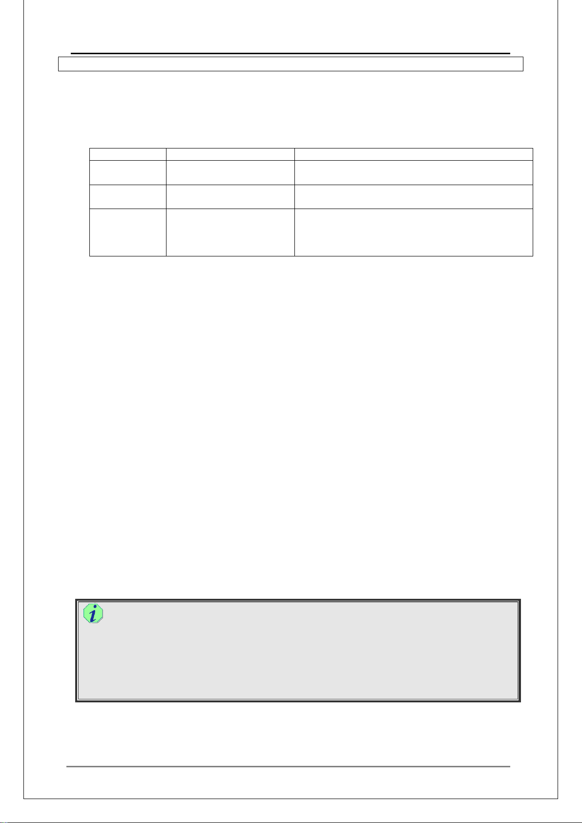
If you che ck the load on the server using the following method, you can tell if there are problems
on the server under the current circumstances or in the current condition. Normally you want to
check the load on the stream servers, but you can also check the load on the DB server in the
same way (if the system is configured by multi-servers).
1. Check the performance w i t h the actual operation or under a similar environ me nt .
2. On the server, execute Performance of the Administrator tools.
3. Right-click on the chart and add t he f ol lowing counters.
4. On the Properties, change the scale as follows: Modify the thickness and color of the line in
the chart so that they are easy t o view.
5. Perform the delivery operations to put load on the server. (This can also be done by client
control on the Server console.) For file delivery, use multiple file contents.
If multiple NICs exist, add the correspo nding nu mber of instances. If multiple DISKs exist,
add the corresponding number of instances.
Points to check
1. Video that is played back on the client
Check for video noise and delay. You can also gain some information by chec king the playba ck
condition status on t he MEDIAEDGE-STB4/STB4H/HDMA-4100 Web Console.
2. CPU load
Check the CPU load. If it reaches 100% even temporarily, performance may degrade. Run the
Task Manager and also ch eck the load on each CPU.
To check performance wit h the Task Manager.
In the Task Manager, click the Performance tab and enable the [One graph per
CPU] option. Confirm that each graph does not reach 100%.
3. Disk Idle
Check disk usage. If that value drops to around 20%, delivery may be influenced. A value of
40% or higher is desirable.
4. Memory
Check memory usage. If that value increases during recording, writing to the disk is not
executing in time, and the data has temporarily been stored in memory.
5. Receive/Send on the network
Check the receive/send values on your network. Normally these values are stable and do not
fluctuate. If they fluctuate by much, delivery/reception may not be executing properly.
6. Read/Write on the physical disk
Check the read/write values on the disk. Normally these values fluctuate somewhat, but
average to a value similar t o t he act ual w r iting/reading bitrate.
If you find any problems in t he above points, server performance may be low er than required.
Page 29

MEDIAEDGE Technical Manual Ver4.10
29
■
Item
Specification
Notes
Model
Express5800 110Gc
Manufacturer
NEC
NIC
Intel Pro 1000 MT
HDD
WDC WD800JD
SATA 80GB cache 8MB 7200rpm
CPU
Intel Celeron D 2.66GHz
Memory
512MB
Type
Model
Manufacturer
Note
Server
Express5800 110Gc
NEC
Switch
DGS-3627
D-link
Everything is in 1000Base-T. Used in
default settings.
Client
STB3
MEDIAEDGE
Live unit
LSB
MEDIAEDGE
HDV input from ADVC-HDM1 (25Mbps)
Item
Setting and condition
Note
TS Packets
Server=7, LSB=7
NIC setting
Default
Disk
Default
Item
Result
Bottle-neck
Note
File delivery
125Mbps (25Mbps x 5)
CPU
Relay
reception
100Mbps (25Mbps x 4)
CPU
Relay delivery
75Mbps (25Mbps x 3)
CPU
25Mbps x 3 for both rel ay
reception/delivery
Relay record
175Mbps (25Mbps x 7)
CPU/
25Mbps x 3 for relay r ecord
operation.
File del ivery +
75Mbps+75Mbps
25Mbps x 3)
CPU/
25Mbps x 1 for relay r eception
operation.
II-2. Validation Results of Server Performance
Below are results of an actual validation. According to other settings and configurations, results
may vary. Note that the values listed in this section have been validated with MEDIAEDGE-STB3
used as a client.
II-2-1. Express5800 110Gc (SATA-HDD model)
Server Specifications
Devices used
Setting condition
V alidation result
Disk Idle
Relay record
Notes
・ When CPU performance is low, operating the Server console or Explorer may increase
the load, resulting in noise on the delivered video.
・ When memory size is small, swapping to virtual memory may occur. If this happens during
maximum load, the system may cr ash and require rebooting.
(File 25Mbps x 3 + Rec
Disk Idle
Crashes with the load of the Explorer
Crashes with the load of the Explorer
Page 30

MEDIAEDGE Technical Manual Ver4.10
30
■
Item
Specifications
Note
Model
Express5800 110Ri-1
Manufacturer
NEC
NIC
Intel Pro 1000 PL / 82566DM-2
82566DM-2 is not used in validation.
HDD
Internal SAS-RAID
RAID-5 / SAS73GB x 3 / Cache 128MB
CPU
Intel Xeon X3350
Quad Core 2.66GHz
Memory
2GB
Type
Model
Manufacturer
Note
Server
Express5800 110Ri-1
NEC
Switch
DGS-3627
D-link
Everything is in 1000Base-T. Used in
Client
STB3
MEDIAEDGE
Live unit
LSB
MEDIAEDGE
HDV input (25Mbps) from ADVC-HDM1
Item
Setting and condition
Note
TS Packets
Server=7, LSB=7
NIC setting
Default
Disk
Default
Item
Result
Bottle-neck
Note
File delivery
500Mbps (25Mbps x 20)
Disk
Relay
reception
125Mbps (25Mbps x 5)
Network
Pro 1000 PL is usable, but relay
reception is not available in 82566DM-2.
File del ivery +
500Mbps+125Mbps
25Mbps x 5)
Disk
25Mbps x 5 for relay record
II-2-2. Express5800 110Ri-1 (SAS-Raid model)
Server Specifications
Devices used
Setting condition
default settings.
V alidation result
relay record
(File 25Mbps x 20 + Rec
/Network
Notes
・ Because it is in SAS-RAID, it demonstrates quite high performa nc e on file delivery.
・ Write cache is set to O FF by default.
・ Because NIC 82566DM-2 performance is low, relay reception (25Mbps x5) is not
available. (It operates but ev entual ly p ac ket l oss o ccur s.) For del iver y and rela y recept ion,
it is recommended that you use Pr o 1000 PL.
Page 31

31
■
Item
Specification
Note
Model
Express5800 120Rj-2
Manufacturer
NEC
NIC
Intel Pro 1000 EB with IO acce leration
Equip 2 ports on-board.
HDD
Internal SAS-RAID
RAID-5 / SAS73GB x 3 / Cache 128MB
CPU
Intel Xeon X5460
Quad Core 3.16GHz x 2
Memory
4GB
Type
Model
Manufacturer
Note
Server
Express5800
120Rj-2
NEC
Switch
DGS-3627
D-link
Everything is in 1000Base-T. Used in
default settings.
Client
STB3
MEDIAEDGE
Live unit
LSB
MEDIAEDGE
HDV input (25Mbps) from ADVC-HDM1
Item
Setting and condition
Note
TS Packets
Server=7, LSB=7
NIC setting
Default
Divide segments with 1 port for delivery,
1 port for relay reception.
Disk
IO = Cached, Write Cache = ON,
Rebuild Rate=low, Consistency
Item
Result
Bottle-neck
Note
File delivery
500Mbps (25Mbps x 20)
Disk
Relay
reception
500Mbps (25Mbps x 20)
CPU
Relay delivery
500Mbps (25Mbps x 20)
CPU
Sends 20 LSB streams to clients
Relay delivery
300Mbps (25Mbps x 12)
Sends 1 LSB stream
Relay record
500Mbps (25Mbps x 20)
Disk
Limit. Crashes by the Explorer operation.
File delivery +
375Mbps+250Mbps
25Mbps x 10)
Disk
25Mbps x 10 for relay reception
File delivery +
200Mbps+375Mbps
25Mbps x 15)
Disk/CPU
25Mbps x 15 for relay reception
II-2-3. Express5800 120Ri-2 (SAS-Raid model)
Server Specifications
Devices used
Setting condition
MEDIAEDGE Technical Manual Ver4.10
ReadCache = AdaptiveReadAhead
check=low, PatrolRead=low
V alidation result
relay record
relay record
(File 25Mbps x 15 + Rec
(File 25Mbps x 8 + Rec
Notes
・ Because it is in SAS-RAID, it demonstrates quite high performance on file delivery and
recording.
・ Write cache is set to O FF by default.
・ Because CPU performance is high, it demonstrates quite high performance on receiving
relay.
Page 32

MEDIAEDGE Technical Manual Ver4.10
32
■
Item
Specification
Note
Model
Express5800 120Rj-2
Manufacturer
NEC
NIC
Intel Pro 1000 EB with IO acce lerat ion
Equips 2 ports on-board
HDD
Internal SATA-RAID
RAID-5 / SATA250GB x 3 / Cache 128MB
CPU
Intel Xeon
Quad Core 2GHz x 2
Memory
4GB
Type
Model
Manufacturer
Note
Server
Express5800
120Rj-2
NEC
Switch
FS-926S
Allied Telesis
Server side: 1000Base-T
Client side: 100Base-TX
Client
STB3
MEDIAEDGE
Live unit
LEB60
MEDIAEDGE
Item
Setting and condition
Note
TS Packets
Server=7, LSB=7
NIC setting
Default
Divides segments with 1 port for delivery,
1 port for relay reception.
Disk
IO = Cached, Write Cache = ON,
ReadCache = AdaptiveReadAhead
Rebuild Rate=low, Consistency
check=low, PatrolRead=low
Item
Result
Bottle-neck
Note
File delivery
200Mbps (10Mbps x 20)
Copying from CD to disk wh ile deli very is
available.
Relay record
100Mbps (10Mbps x 10)
File deli ve ry +
200Mbps+100Mbps
10Mbps x 10)
10Mbps x 1 for relay r eception
II-2-4. Express5800 120Ri-2 (SATA-Raid model)
Server Specifications
E5405
Devices used
Setting condition
V alidation result
relay record
(File 10Mbps x 20 + Rec
Notes
・ This is a validation result of S D o n STB3.
Page 33

33
■
Item
Specification
Note
Model
PowerEdge 2950 III
Manufacturer
DELL
NIC
Broadcom BCM5708 C Ne t Xtreme II
Equips 2 ports on-board
HDD
Internal SATA-RAID
RAID-5 / SATA 1TB x 6 / Cache 256MB
CPU
Intel Xeon E5410
Quad Core 2.33GHz
Memory
4GB
Type
Model
Manufacturer
Note
Server
PowerEdge 2950 III
DELL
Switch
DGS-3627
D-link
Everything is in 1000Base-T. Used in
default settings.
Client
STB3
MEDIAEDGE
Live unit
LSB
MEDIAEDGE
HDV input (25Mbps) from ADVC-HDM1
Item
Setting and condition
Note
TS Packets
Server=7, LSB=7
NIC setting
TOE=invalid
Divides segments with 1 port for
delivery, 1 port for relay reception.
Disk
IO = Cached, Write Cache = ON,
ReadCache = AdaptiveReadAhead
Rebuild Rate=low, Consistency
check=low, PatrolRead=low
Factor
Result
Bottle-neck
Note
File delivery
175Mbps (25Mbps x 7)
Network
If it’s surpasses 200Mbps, data can not
be sent properly to client s.
File delivery
250Mbps (25Mbps x 10)
Network
On NIC on the server side, Intel Pro1000
PT is used.
Relay
reception
175Mbps (25Mbp s x 7)
Network
If it’s surpasses 200Mbps, data can not
be sent properly to client s.
File del ivery +
175Mbps+250Mbps
25Mbps x 10)
Disk/CPU
25Mbps x 10 for relay r ecept ion
II-2-5. PowerEdge 2950 III (SATA-Raid model)
Server Specifications
Devices used
Setting condition
MEDIAEDGE Technical Manual Ver4.10
V alidation result
relay record
(File 25Mbps x 7 + Rec
Notes
・ Although it is in SATA-RAID, because the number of disks, capacity, and cache are big, it
demonstrates high disk p erformance.
・ Disk Idle drops down ab out once per hour, caus ing packet loss.
Page 34

MEDIAEDGE Technical Manual Ver4.10
34
■
■
■
■
II-3. Performance of the Network Switch
II-3-1. Key points of the network switch
Key points of the netw ork switch are:
1. Speed o f eac h por t
Everything is in 1000Base / 1000Base for uplink, 100Base for others/everything is in 100Base
2. Delivery performance of unicast
3. Delivery performance of multicast
II-3-2. Port Speed
1. Everything is in 1000Base (Full gigabit switch)
This is most suitable for MEDIAEDGE4. While the s erv ers can u se s ufficient bandwidth, pac ket
loss is reduced when a client is linked with 1000M .
2. 1000Base for Uplink
Although connecting a client with 100M can provide good cost performance, it can also cause
packet loss. Be sure to validate b ef or e use.
3. Everything Is in 100Base
Using 100Base for everything means that server features cannot be delivered fully. This
configuration can be acceptable if you have only a few clients and live units, and the sum of all
streams is within the limit of the 100Base-TX (60Mbps).
II-3-3. Delivery Performance of Unicast
Delivery performance of unicast using a network switch normally does not cause problems. When
using a router, however, pay attention to the throughput. On the MEDIAEDGE system, the actual
bitrate that can be delivered is low er than the bitrate, sometimes by as much as half.
Some switches with QoS functions may be set to "Not prioritized" by default. In that case, when
multiple streams flow simultaneously and a certain amount is accumulated in the buffer, the data
may be rejected, leading to video distortion or a blank screen upon playback on the clients. It is
recommended that y ou set t he switch to prioritize the MEDIAEDGE stream, if at all possible.
II-3-4. Delivery Performance of Multicast
Delivery performance of multicast may be low in some inexpensive switches that operate lower
than 100Mbps. Before executing a multicast delivery, be sure to perform a thorough val idation.
Also note that, even when some multicast streams can be delivered from a server, if an additional
live unit is added for multicast delivery, the multicast source increases. This may reduce system
performance.
Page 35
MEDIAEDGE Technical Manual Ver4.10
35
■
■
Client Type
Delivery Method
Data
Reception
Unicast
MPEG2-SD
2M - 15M bps
MPEG2-HD
15M - 30M bps
H.264
1M - 20M bps
Multicast
MPEG2-SD
2M - 15M bps
MPEG2-HD
15M - 30M bps
H.264
1M - 20M bps
II-4. Reception by Clients
II-4-1. Reception on MEDIAEDGE-STB4/STB4H/HDMA-4100
MEDIAEDGE-STB4/STB4H/HDMA-4100 has an Ethernet port compatible with 10BASE-T
(IEEE802.3)/100BASE-TX (IEEE802.3u)/1000BASE-T (IEEE802.3ab) and supports full-duplex
and auto-negotiation. Connection to switching hub with a port supporting full-duplex 1000BASE-T
is recommended.
When connected to half-duplex repeater hub, stream flow may be hindered by other devices
connected to the same network or by communication with other devices, therefore the Ethernet
line will not be very effi cient. In such configuration, high quality streams cannot be delivered.
To deliver high quality streams from server to the client, more line capacity the better, and a
network configuration us in g 1000Mbps or 100Mbps Ethernet switching hub is recommended.
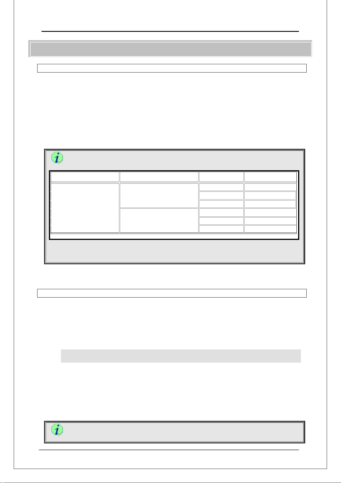
Delivered data types and reception capabilities of MEDIAEDGE-STB4/STB4H/HDMA-
4100
STB4/STB4H/
HDMA-4100
*1
*1 Amount of data one MEDIAEDGE-STB4/STB4H/HDMA-4100 can process
-> Multicast stream + stream reception = up to 500M bps
・ When MEDIAEDGE-STB4/STB4H/HDMA-4100 unit is linked in 100Base-TX, frequent
packet losses may occur on some network switches.
II-4-2. Reception by MEDIAEDGE-SWT4
Since MEDIAEDGE-SWT uses computers, it is affected by capabilities of NIC installed on the
computer.
* On Windows Vist a or later, the number o f the receiv e d pa c kets v ia netw or k is l imit ed by M M CSS
(Multimedia Class Sched uler Service)
You can specify the limit to a certain value (number of packets that MEDIAEDGE-SWT4 can
receive per second) by changing the following registry value:
HKEY_LOCAL_MACHINE\SOFTWARE\MICROSOFT\Windows NT\CurrentVersion\Multimedi
a\SystemProfile NetworkThrottlingIndex
Under the Ethernet environment (packet length: 1500byte), if the number of packets is (10),
according to the follow ing formula, it’s lim ited at 120Mbps approximately.
1500(byte) x 10 (packets) x 8 (bit) x 1000 (millisecond) = 120,000,000 (120Mbps)
Based on this formula, calculate the value according to network environment, content bitrate
and number of pac ket s.
The upper limit of the received packets is 100Mbps at the default value “10”. To disable
the limit to receive packets surpassing it, set the registry to “FFFFFFFF”.
Page 36

MEDIAEDGE Technical Manual Ver4.10
36
■
■
■
II-5. Delivery on the Live Unit
II-5-1. Understanding the Delivery
Two kinds of stream are delivered from live unit s: unicast and multicast.
1. Unicast (MEDIAEDGE-LSB/LEB60)
Can send one stream at a time, to a single client. When a delivery is requested from a second
client, the later request is canc eled and the current delivery continues.
2. Unicast (MEDIAEDGE-LEB4)
Can send one stream to multiple clients via unicast. N ote that the maximum number of the
clients are determined depending on the bitrate of the stream.
3. Multicast
Can send one stream at a time, to multiple clients simultaneously. Therefore playback can be
performed simultaneously on multiple clients.
When delivery mode is set to automatic, the live unit automatically starts sending in multicast
when it is started up.
II-5-2. Understanding the Relay
When a stream (relay) server is started up, it connects to the live unit and becomes ready to
receive streams. Therefore, even though you do not specify delivery or recording of the relay
content, the streaming bandwidth is always occupied when the server is started up.
II-5-3. Multicast Packets
Although a live unit can deliver multicast packets, when another live unit or a server on the same
network delivers multicast packets, the first live unit cannot help but receive those packets,
depending on the network configuration. When a live unit receives too many such packets, it
cannot receive other p ackets, making it impossible to control properly.
Configure the system so that multicast packets that come in are up to 60Mbps for 100Base-TX,
and 500Mbps for 100 0Base-T connections.
Page 37

MEDIAEDGE Technical Manual Ver4.10
37
III.
MEDIAEDGE System Design
Page 38

MEDIAEDGE Technical Manual Ver4.10
38
■
■
III-1. System Design Guideline
MEDIAEDGE system has many functions, including VOD, scheduled playback, and live delivery.
These functions, along with the whole setup of the system, can be customized according to the
targeted effe cts by the users.
In order to design the system, the requirements on the network configuration and the server
performance can be decid ed based on the following factors.
III-1-1. Required items for system requirements
・ Number of the clients, and the physical placement.
・ Content type/bitrate
・ Capacity of contents to retain (time x bitrate)
・ Delivery method
・ Content selection method (menu/control)
・ Client settings (IP address/settings)
・ Live unit usage
・ Availa b ility of recording
・ Other functions
・ Redundancy of the server
III-1-2. Setting factors decided from the required specifications
・ Network topology ( configuration)
・ Number/performance of servers (Model selection)
・ Number/perfor ma nce of network switch (Model selection)
・ Number/performance of clients (Computer selection for MEDIAEDGE-SWT4 operation)
・ Additional software
Scheduler softwar e, serial control, content transfer
Page 39

MEDIAEDGE Technical Manual Ver4.10
39
Content bitrate
Capacity
hour
40GB
80GB
500GB
1TB
2Mbps
About 1.0GB
40 hours
80 hours
500 hours
1000 hours
4Mbps
About 1.9GB
21 hours
42 hours
263 hours
526 hours
6Mbps
14 hours
28 hours
178 hours
357 hours
8Mbps
10 hours
21 hours
135 hours
270 hours
10Mbps
8 hours
17 hours
108 hours
217 hours
15Mbps
3.4 hours
11 hours
72 hours
144 hours
18Mbps
4.8 hours
9.7 hours
60 hours
121 hours
25Mbps
About 11.4GB
3.5 hours
7 hours
43 hours
87 hours
III-2. Capacity of the Content Drive
This section describes the c apacity required to store MPEG files for MEDIAEDGE.
Based on the bitrate and the t otal playback time of the file, the required ca pacity is:
Duration of v i de o ac cording to content bitrat e and disk capacity
(When audio bitra t e is 224Kbps)
required for 1
About 2.8GB
About 3.7GB
About 4.6GB
About 6.9GB
About 8.2GB
The actual file size is larg er t han t hese values because of the overhead for th e M PEG system.
The actual disk size is smaller t han t hese values because of the disk format.
Also note that, because drive capacity is calculated with 1Gbytes = 1,000,000,000Bytes but OS
disk capacity is calculated with 1Gbytes = 1024 x 1024 x 1024 bytes, there will be a slight
difference.
Page 40

MEDIAEDGE Technical Manual Ver4.10
40
■
●
●
●
●
III-3. Data delivered on the Network
III-3-1. Performance and limitations of MEDIAEDGE system regarding streaming data
MEDIAEDGE must be configured with the following li mitations considered.
* While bitrate values lower than the minimum limit can be specified (the minimum limit is 1/3
of the lowest range), doing so may decrease video quality. If you set a lower value, be sure to
check the encoded dat a.
Video format avail abl e for streaming (MEDIAEDGE-SVS4)
Video format Video resolution
1080i 1920x1080 15000 - 30000
720p 1280x720
MPEG2
H.264
Video format avail abl e for streaming (MEDIAEDGE-LEB4)
Video format Video resolution
H.264
Video format avail abl e for streaming (MEDIAEDGE-LEB60)
Video format Video resolution
MPEG2
Video format avail abl e for streaming (MEDIAEDGE-LSB + ADVC-HDM1)
Video format Video resolution
MPEG2
Full-D1
Half-D1 352x480 352x576 2000 - 8000
SIF 352x240 352x288 1000 - 8000
1080i 1920x1080
720p 1280x720
1080i
720p 1280x720 4000 - 10000
Full-D1 720x480 720x576 2000 - 10000
MPEG1 352x240 352x288 1000 - 1800
Full-D1
VGA 640x480 3000 - 15000
Half-D1 352x480 352x576 2000 - 8000
SIF 352x240 352x288 1000 - 4000
QCIF 176x144 256 - 2000
HDV
ADVC-HD
M1
720x480 720x576 4000
704x480 704x576 3000 - 15000
1920x1080 5000 - 20000
1440x1080
720x480 720x576
704x480 704x576 3000 - 15000
1920x1080
1280x720 25000
1920x1080
1280x720 11000 - 30000
Bitrate (kbps)
MPEG file
15000
25000
25000
- 30000
- 15000
1000 - 20000
Bitrate (kbps)
5000
- 20000
Bitrate (kbps)
LEB60
4000 - 15000
Bitrate (kbps)
LEB4
LSB
Page 41
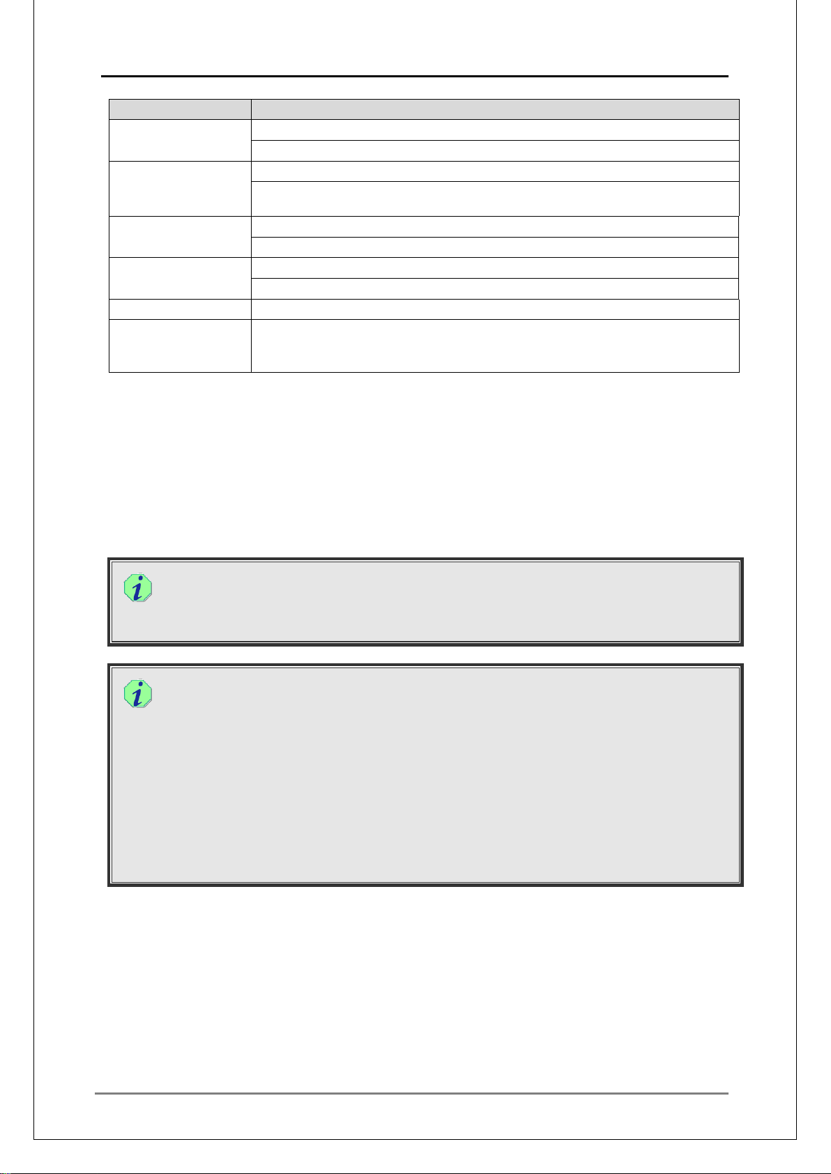
MEDIAEDGE Technical Manual Ver4.10
41
●
Limitations
Name/Function Limitations or notes
MEDIAEDGE
Stream Server
MEDIAEDGE-STB4
MEDIAEDGE-STB4H
HDMA-4100
MEDIAEDGE-LEB4 Up to 60M bps of multicast data in total can be entered when linked in 100BASE-TX
MEDIAEDGE-LSB Up to 60M bps of multicast data in total can be entered when linked in 100BASE-TX
MEDIAEDGE-LEB60 Up to 60M bps of multicast data in total can be entered.
Live video Up to 4 live videos is available for a MEDIAEDGE Stream Server. (Up to 8,
Up to 60M bps of stream data in total for a 100BASE-TX NIC.
Up to 500M bps of stream data in total for a 1000BASE-T NIC.
Up to 60M bps of stream data in total can be received when linked in 100BASE-TX
Up to 500M bps of stream data in total can be received when linked in 1000BASE-T
Up to 500M bps of multicast data in total can be entered when linked in 1000BASE-T
Up to 500M bps of multicast data in total can be entered when linked in 1000BASE-T
theoretically).
(Optional OHCI board is required for an input channel of live video.)
The above limitations are the software specifications of the MEDIAEDGE system.
According to the performance of your server and network configurations, some features may not
be available.
When VOD is used from multiple clients, the load on the stream server’s hard disk will become
heavy. The number of units that can be accessed varies depend ing on the speed of the dis k drive
and the RAID configurations.
To calculate the amount of streams, v ideo bitrate is used. I f the content is in VB R, use the
maximum bitrate for calculations.
As the actual dat a contains packet headers and audi o str eam, t he siz e wi ll be b igg er tha n
the calculated value.
In stream delivery utilizing the "FEC" (Forward Error Correction) function, the stream is
delivered with redundant packets for correcting the corrupt data generated by FEC
parameters (Number, Interval).
Even when the delivered packet is damaged, it can be repaired by redundant packets.
This is a very useful function w hen you are delivering video under a WAN environment.
Note that the total amount of bitrate increases.
Regarding the video bitrate in FEC mode, the amount of the stream can be calculated
from the bitrate found in the “MEDIAEDG E Technical Manual - Technical Ref er ences -".
* The video delivered from the MEDIAEDGE-LSB/LEB4/LEB60 wher e F EC is enabled is
relayed by MEDIAEDGE-SVS4, and the stream is relayed in the same bitrate,
regardless of the FEC setting on the MEDIAEDGE-SVS4.
Page 42
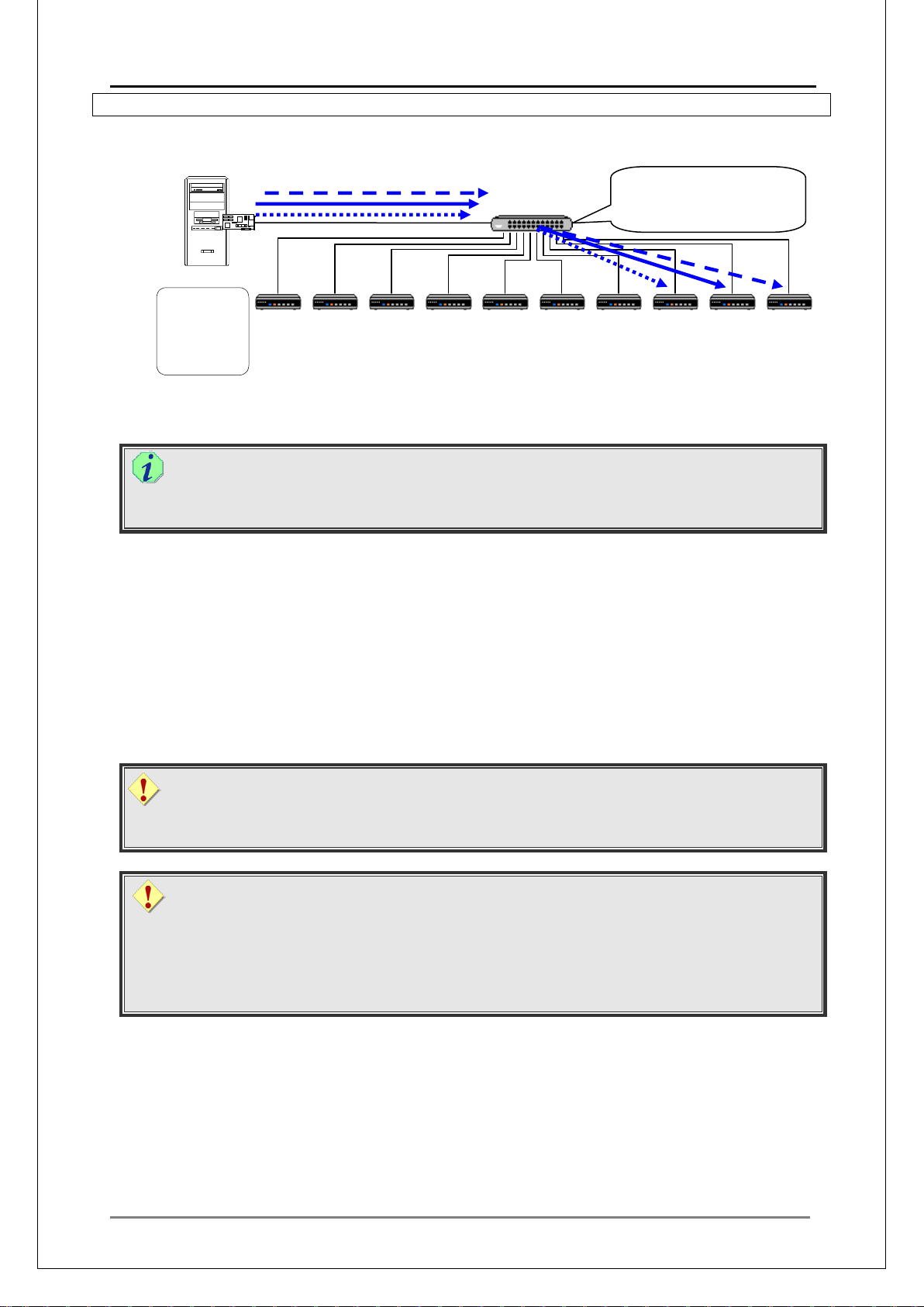
MEDIAEDGE Technical Manual Ver4.10
42
■
▼
▼
Unicast stream is switched by
the switching hub, so as to be
Unicast
III-3-2. Using only "unicast delivery"
NIC
Switching HUB
delivered only to the client.
MEDIAEDGE-SVR
Stream server
DBMS server
Web server
DNS server
DHCP server
STB4 STB4 STB4 STB4 STB4
STB4
STB4 STB4
STB4
When only the Unicast is used, the total amount of the stream data delivered from the stream
server is calculated by the following formula.
Total amount of the stream data delivered when only the Unicast i s used
Total amount of stream data delivered (Mbps) = Content max bitrate (Mbps) x Number
of clients
STB4
For example:
When an MPEG2-HD file of 18Mbps is used as a cont ent and
when an NIC in 100BASE-TX is used in the stream server:
18Mbps x 3 = 54Mbp s < 60Mbps (Maximum limit of 100BASE-TX)
Up to 3 clients can be connected.
when an NIC in 1000BASE-T is used in the stream server:
18Mbps × 27 = 486Mbps < 500Mbps (Maximum limit of 1000BASE-T)
Up to 27 clients can be co nnect ed.
Live video
Similar to the MPEG file delivery, the bitrate for the live video delivery can be calculated
by the bitrate (Mbps).
Number of clients that can be connected
Note that the number o f clients ca lcul ated h ere i s a r ough estim ate. Pr eli minar y operat ion
tests may be required depending on the hardware specifications.
The load on the stream server’s hard disk can be heavy. The number of connectible
clients varies accordin g t o the speed of the disk drive and the RAID configurat ions.
Page 43
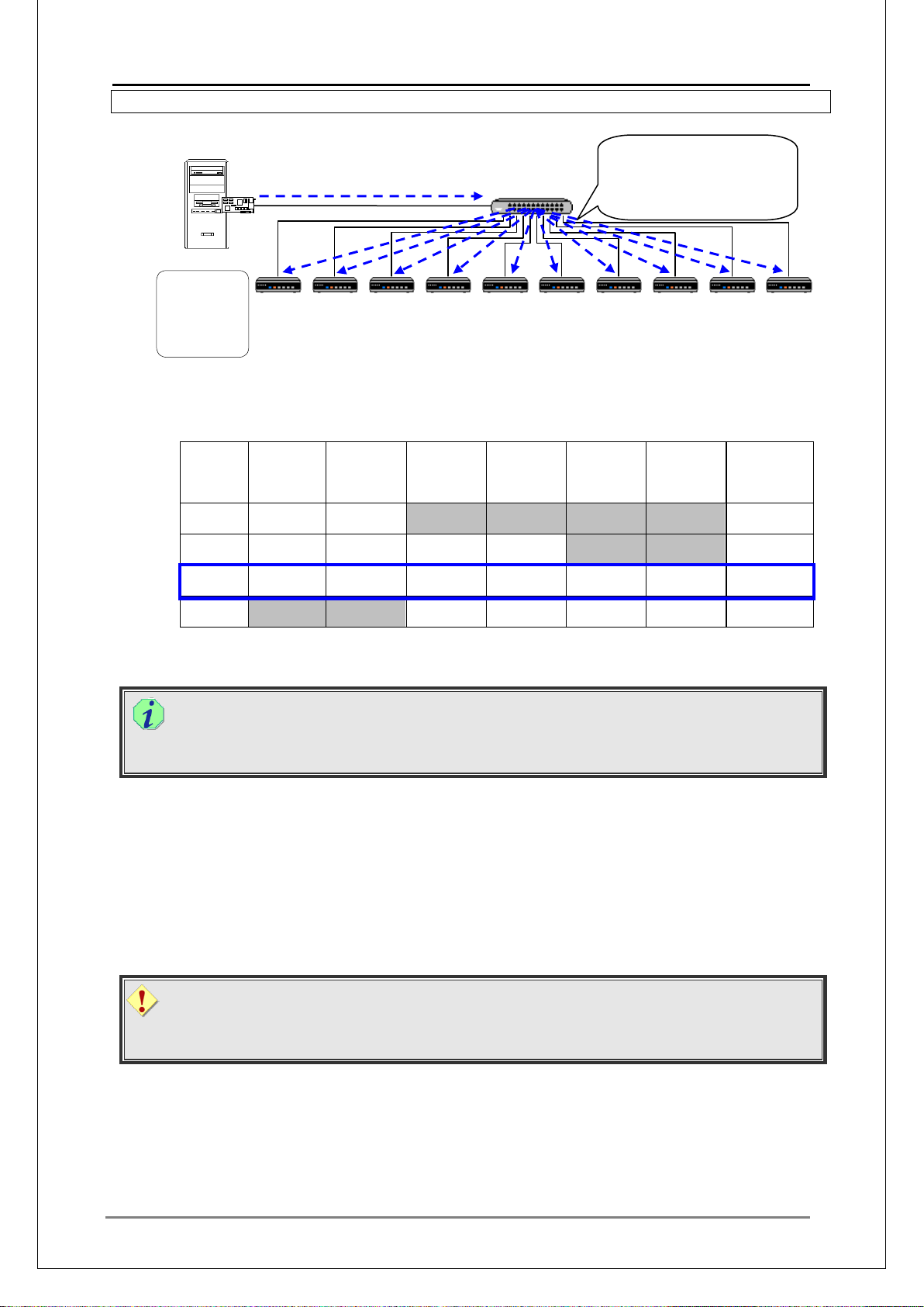
MEDIAEDGE Technical Manual Ver4.10
43
■
6M
6M
None
None
None
None
12M
6M
6M
20M
20M
None
None
52M
6M
Content
6M
Content
20M
Content
20M
Content
25M
Content
25M
Content
102M
None
None
20M
Content
20M
Content
25M
Content
25M
Content
90M
Multicast stream is delivered
s being
Multicast
III-3-3. Using only "multicast delivery"
NIC
Switching HUB
to all the clients connected,
regardless whether it’
watched.
MEDIAEDGE-SVR
Stream server
DBMS server
Web server
DNS server
DHCP server
STB4 STB4 STB4 STB4 STB4
STB4
STB4 STB4
STB4
In multicast delivery, sum the bitrate of each channel for period of time, and use the value to
find the maximum sum.
For example, in the following video delivery schedule:
Total
Start at Channel1 Channel2 Channel3 Channel4 Channel5 Channel6
10:00 -
11:00 -
12:00 -
Content
Content
Content
Content
Content
Content
Amount of
Stream
Data
STB4
13:00 -
The "12:00 –" period is the highest peak, and its total amount of stream data is 102Mbps.
Multicast
Generally, in "Schedule delivery ( M ulticast)," the total amount of the delivery stream data
and the amount of the stream data which video clients receive, are the same.
Unlike Unicast, a Multicast stream will be deliv ered t o all the clients. In the above example, if
all the clients connected to the switching hub are linked up via 1000BASE-T, any channel
can be viewed from any client. In those cases, there is no theoretical limit on the number of
the clients that can be co nnected.
However , if ther e is even one c lient t hat is l inked u p v ia 100BASE-TX, when the total amount
of the stream exceeds 60Mbps, then the entire network may not work properly, causing
playback troubles on every channel.
Bitrate for live video
Similar to the MPEG file deliver y, the bitrate for t he live video can be calculated by the
bitrate (Mbps).
Page 44
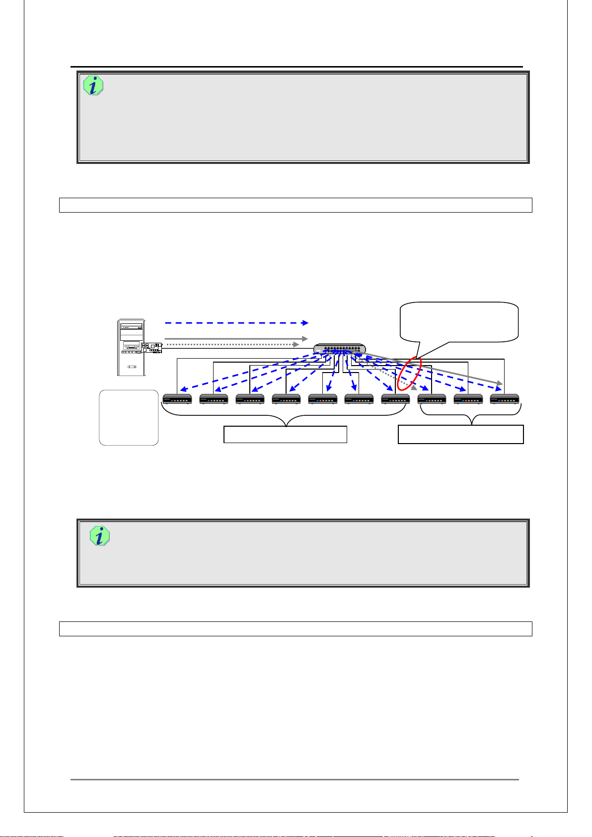
MEDIAEDGE Technical Manual Ver4.10
44
■
■
Multicast
Unicast
Video on Demand clients
How to realize multicast d elivery exceeding 60Mbps when clients that are connected via
100BASE-TX exist among other clients connec t ed via 1000BASE-T
When the total amount of the stream data is larger than 60Mbps, this m eans it surpasses
the limit of 100BASE-TX, but by using an IGMP router, L3 switching hub and L2 switch
that supports IGMP Snooping, the multicast packets can be controlled, thus allowing
delivery of larger multicast data.
III-3-4. Using "unicast deliver y" and "multicast delivery" simultaneously
Calculate the maximum amount of stream data delivered and the amount of stream data received
by clients.
For example:
Schedule playback and Video on Demand are performed as be low.
Switching HUB
Multicast data will be
delivered to the Video on
Demand clients also.
NIC
MEDIAEDGE-SVR
Stream server
DBMS server
Web server
DNS server
DHCP server
STB4 STB4 STB4 STB4 STB4
Scheduled playback clients
スケジュール再生専用端末 VOD 専用端末
STB4
STB4 STB4
STB4
STB4
The Multicast data for schedule playback will be delivered to all the clients on the same
network. Even though the clients are divided according to usage as shown above, the
multicast data for sch edule playback will be delivered to all the clients.
Amount of Stream Data
The total amount of stream data sent and stream data rece iv ed by a client is the sum of
the values found in "■ III-3-2 Using only "unicast delivery"” and "■ III-3-3 Using only
"multicast delivery"”.
III-3-5. Using MEDIAEDGE-LSB/LEB4/LEB60
MEDIAEDGE-LSB/LEB4/LEB60 can deliver live stream even in st and-alone mode.
● Single Delivery system without server (Unicast)
In the unicast delivery of MEDIAEDGE-LEB60, you can choose an encode mode from the 5
presets for streaming data.
In the unicast delivery of MEDIAEDGE-LEB4, the data is delivered in the parameters (such
as bitrate) specified in advance according to the input resolution.
In the unicast delivery of MEDIAEDGE-LSB, data is delivered in the specified parameters
when the unit is connected to ADVC-HDM1, in the output settings of the camera when it’s
connected to a camera.
Page 45
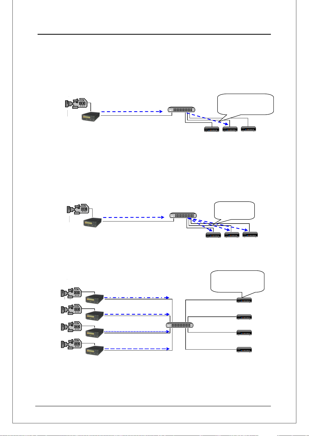
45
The available client for MEDIAEDGE-LSB/LEB60 is limited to only one unit. The
Unicast×1
○ × ×
Multicast
Multicast
MEDIAEDGE-LEB4 can have perform unicast distribution to multiple clients.
While the number of the a vailable c lients t o MEDIAEDGE-LEB4 can be speci fied betwee n 1
to 16, the actual number of the client s v aries de pen ding on b itrat e of deliver y, FEC settings,
and network status. When the delivery condition changes, and exceeds the delivery
capacity, all the delivery fails.
To realize the similar functions on MEDIAEDGE-LSB or MEDIAEDGE-LEB60, utilize the
relay functions of MEDIAEDGE-SVS4.
LSB/LEB
● Single delivery system without serv er (Multicast)
In the multicast delivery of MEDIAEDGE-LEB60, multicast stream can be delivered using
any of the preset encode modes.
In the multicast delivery of MEDIAEDGE-LSB, contents can be delivered with the values
(bitrate, etc) specified in a dvance according to the input resolution.
The number of clients w here the cont ent can be v iewed is the oretical ly unli mited. Practic ally
though, the number varies depending on the network configuration.
LSB/LEB
● Multi delivery system without server
With multiple MEDIAEDGE-LSB/LEB4/LEB60 units used, and if each MEDIAEDGELSB/LEB4/LEB60 delivers multicast streams, video can be switched and viewed by each
client.
LSB/LEB
LSB/LEB
LSB/LEB
LSB/LEB
MEDIAEDGE Technical Manual Ver4.10
Switching HUB
Switching HUB
Switching HUB
Can be viewed by one of
the clients (if the stream
is sent from LSB/LEB60)
STB4
STB4
STB4
Can be viewed by
any client.
STB4
Video from any camera
can be viewed by each
client.
STB4
STB4
STB4
STB4
STB4
STB4
Page 46
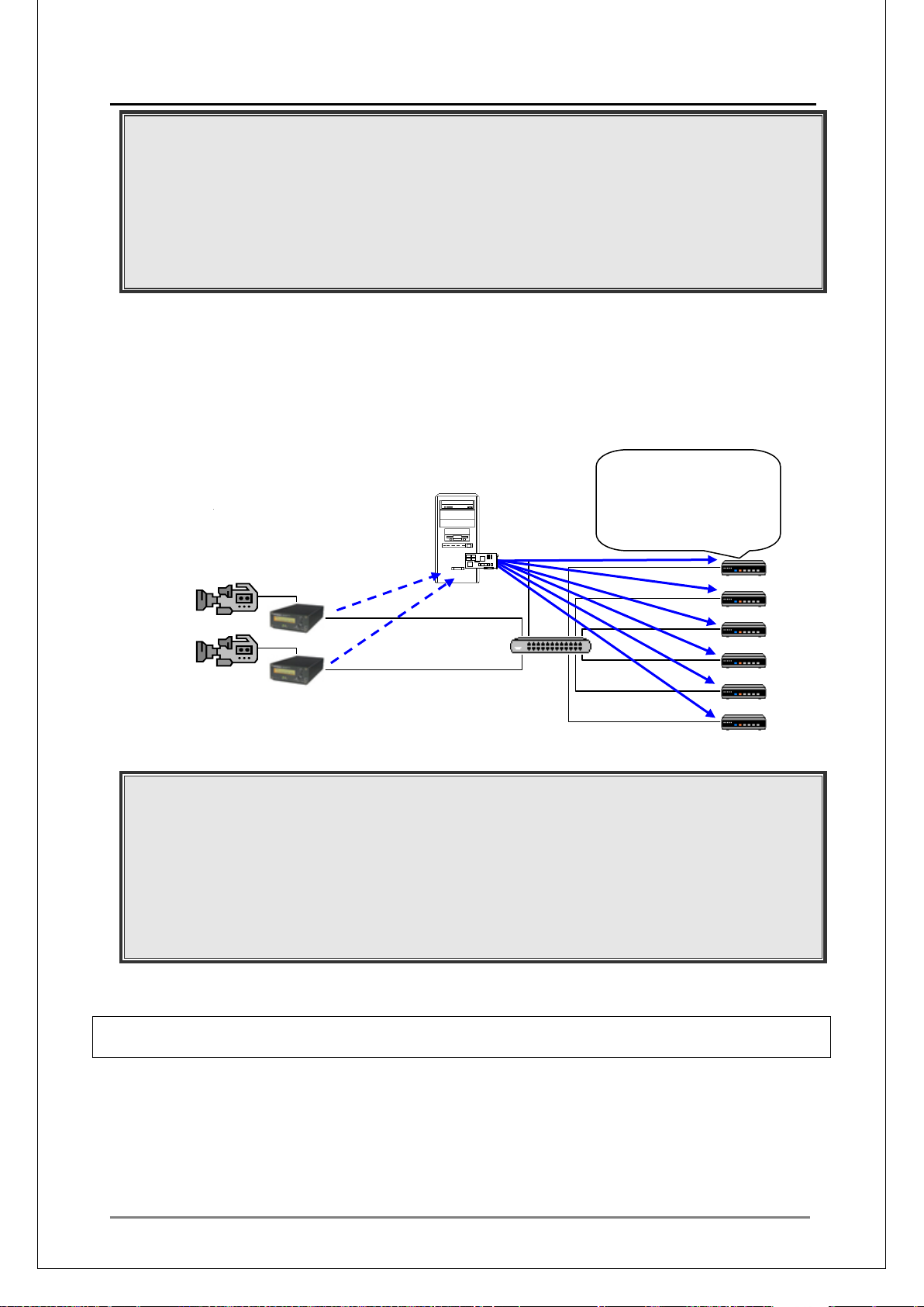
MEDIAEDGE Technical Manual Ver4.10
46
■
Unicast
Unicast/Multicast
Multicast data will be delivered not only to clients but also to MEDIAEDGE-LSB/LEB4/
LEB60.
Multicast data will be delivered to all the units connected to the switching hub. As
MEDIAEDGE-LEB60 and MEDIAEDGE-STB4/STB4H/HDMA-4100 are connected in
100BASET-TX, the stream data must be less than 60Mbps.
MEDIAEDGE-STB4/STB4H/HDMA-4100 has to be set to Channel mode, and each
MEDIAEDGE-LSB/LEB4/LEB60 content has to be preset.
(Remote control of contents using STB menu is not available.)
● Combination with a server (MEDIAEDGE-SVS4 is used)
Utilizing the content relay function of the MEDIAEDGE Server, features such as delivering
the video from a MEDIAEDGE-LSB/LEB4/LEB60 to mul tiple clients and recording will be
available, along with the Video on Demand mode and the schedule delivery.
A combination of the MEDIAEDGE-LSB/LEB4/LEB60 (a small unit whose setup location is
hardly limited by its size) and the MEDIAEDGE-SVS4 (which has flexible video delivery
functions) is very useful.
MEDIAEDGE-SVR
NIC
LSB/LEB
LSB/LEB
Switching HUB
Each client can choose from
"Video on Demand,"
"schedule delivery," or
"video from camera" to
view.
STB4
STB4
STB4
STB4
STB4
STB4
Multicast data will be delivered not only to video clients but also to MEDIAEDGE-LSB/
LEB4/LEB60.
Multicast data will be delivered to all the clients connected t o t he s w itc hing hub. Because
MEDIAEDGE-LEB and MEDIAEDGE-STB4/STB4H/HDMA-4100 are connected in
100BASET-TX, the stream data must be less than 60Mbps. (When linked in 100Mbps,
MEDIAEDGE-STB4/LSB also has similar limitations.)
From the MEDIAEDGE-STB4/STB4H/HDMA-4100, content can be selected with a menu
screen, or viewed in Channel mode.
III-3-6. Improving Multicast Delivery Performances over the Network Using IGMP
Snooping
In a network configuration using switching hubs, multicast packet is delivered to all clients,
therefore when the server has high del ivery c apabilit ies, recepti on cap acity of the clie nts bec ome a
problem.
In this case, configuring a network with an IGMP compatible router and a L3 switch will allow
delivery of multicast packets only to the clients with av aila bl e r eception.
In IPv6, configuring a network with an MLDv2 compatible router and a L3 switch produces the
similar effect.
Page 47

MEDIAEDGE Technical Manual Ver4.10
47
■
[
•
×10M
Max Bitrate of
Number of clients
(b)
•
Content Bitrate
Mbps
Mbps
Mbps
Mbps
Mbps
Total (bps)
×10M
(e)
Max Bitrate of
(f)
M
⇒
2
40
2 8 12
20
60
8
×
5
=
0
2 8 2
8
12
20
28
8
III-3-7. Calculation of the stream data
Calculate the total amount of the video stream in order to determine the system construction.
Use the following Stream Data Calculation Sheet to calculate the total amount of sent stream
data and the total a m ount of stream received by the clients.
Note that the live video in live v ideo delivery can be calculated similar to MPEG cont ents.
In the FEC mode, see the bitrate listed in [S t ream Dat a Calculat ion Sheet] to est imate the
amount of the stream.
Example]
5 STB4s are used as clients, and there are 5 contents of 8Mbps, 10 contents of 6Mbp s, and 2
contents of 4Mbps which are used as Video on Demand, and 2 Channels of contents of
6Mbps, and 2 Channe ls of contents of 4Mbps are used as S chedule delivery.
(Live video is not used)
Strea m server: Total amount of stream data to send.
Content bitrate
Number of contents
for simultaneous
schedule delivery
(Multicast)
2Mbps 4Mbps 6Mbps 8Mbps 10Mbps
contents
×2M
=
Contents
=
M
×4M
M
contents
×6M
=
M
=
contents
×8M
contents
=
M
M
(a)
Total (bps)
M
Video on Demand
(Unicast)
content
M bps units
Stream server: Amount of stream data to send Total
Client: Total amount of stream data to r eceive.
Number of contents
for simultaneous
schedule delivery
(Multicast)
Video on Demand
(Unicast)
2
contents
×2M
=
content
M bps
4
contents
×4M
=
M
M
6
contents
×6M
=
Number of live streams
8
contents
×8M
=
M
M
10
contents
=
M
(c)
(d)
Copy to
M
M
M
M
Client: Amount of stream data to receive Total
(g)
Page 48

MEDIAEDGE Technical Manual Ver4.10
48
•
×10M
M
Max bitrate of
Number of clients
M
M
•
Content Bitrate
Mbps
Mbps
Mbps
Mbps
Mbps
Total (bps)
×10M
M
Max Bitrate of
M
M
×
=
⇒
Stream Data Calculation Sheet
Use this sheet to calculate t he am ount of stream data for the stream server and the clients.
Note that the live video in live v ideo delivery can be calculated similar to MPEG cont ents.
Strea m server: Total amount of stream data to send.
Content bitrate
Number of contents
for simultaneous
schedule delivery
(Multicast)
Video on Demand
(Unicast)
2Mbps 4Mbps 6Mbps 8Mbps 10Mbps
contents
×2M
=
content
M bps units
contents
=
M
×4M
M
contents
×6M
=
M
=
contents
×8M
contents
=
M
(a)
M
(b)
Total (bps)
Stream server: Amount of stream data to send Total
Client: Total amount of stream data to r eceive.
2
Number of contents
for simultaneous
schedule delivery
(Multicast)
Video on Demand
(Unicast)
contents
=
M bps
×2M
=
M
content
Client: Amount of stream data to receive Total
4
contents
×4M
M
6
contents
×6M
=
Number of live streams
8
contents
×8M
=
M
M
10
contents
=
M
Copy to
(c)
(d)
(e)
(f)
(g)
Page 49
49
III-4. Improving System Performances
■
■
III-4-1. Improving Networ k Perf or ma nce s
Improving Performances Using Multiple NICs
Amount of stream data delivered can be increased by using multiple NICs. This will allow
additional clients per server. Numbers of NICs that can be used simultaneously depends on
the capabilities of the server used.
Improving Performances Using a Gigabit Ethernet
By using a gigabit Ethernet (i.e. 1000Base-T), delivery will be dramatical ly improv ed compar ed
to 100Base-TX. In this case, a 1000Mbps compatible hub must be implemented where the
server will be connected.
Gigabit Ethernet (1000BASE-T) is heavily affected by the capabilities of the NIC and PCI bus.
The amount of video data that can be exported is a maximum of 500Mbps per NIC.
III-4-2. Server Load Dispersion
MEDIAEDGE Technical Manual Ver4.10
MEDIAEDGE Servers should be operated with the below configurations:
1. Strea m server (contents server)
2. Database server
3. DHCP server
4. DNS server
5. Web server for Server console
6. Web server for clie nt cont ents
In a system with a small lo ad, all funct ions c an phy sical ly be oper ate d on o ne ser ver (single ser ver
configuration). On the other hand, a large-scaled system with a heavy load requires operation on
multiple servers (multi-server configur ation).
"When load on the stream ser ver becomes a burden…"
When the database is accessed or the Web server is operated by a heavily loaded
stream server, database access takes a long time leading to lowered response and
stream server throughput, ending up with degraded quality images. Files may not be
saved correctly during liv e rec or di ngs.
Spreading Out the Server Load
By setting up the server with the heaviest load on a separate computer, the load can be
dispersed. When the numbers of clients or streams to be delivered is large, burden on the
stream server will be even larger. By spreading out the server as below, based on the
requested delivery performance, burden on streaming can be dispersed.
1. Separating NIC for Relay Reception and Delivery
Assign one NIC to receive the stream from the LSB/LEB4/LEB60, and the other NIC to
deliver the stream to the clients. With this setting, MEDIAEDGE can be operated without
affecting the distribution on the delivery.
2. Stream Server Dispersion
To reduce the load on a stream server, configure the system with separate servers, one
for the stream server and one for another server. This will relieve the burden on the
stream server from Web services and database acc ess, allow ing use of all its capacity for
streaming.
Page 50

MEDIAEDGE Technical Manual Ver4.10
50
3. Multiple Stream Server Configuration
In a system where the amount of streams to be delivered is greater than the capacity of
one stream server, multiple stream servers will be required. This system will consist of
one database server ( including Web, DHCP, and DNS) and multiple stream servers.
4. Separating NIC for Streaming and Database Access
Each stream server will have two NICs (network interface), one for streaming and the
other for connecting with the database server. This will suppress traffic on the
stream-side during database access. Also, by using segmentation for database access,
the Server console can be oper at ed w it hout affecting the traffic on the st r eam-side.
Page 51

MEDIAEDGE Technical Manual Ver4.10
51
■
Conditions (Server)
Delivery Performance
Packet Size
Comments
Celeron 2.6GHz
35Mbps
TS Packets=7
Delivers a LEB
content
Celeron 2.6GHz
1000Base-T
200Mbps
TS Packets=128
Delivers a LEB
Delivers contents
III-4-3. TS Packets
Changing the number of the TS packets delivered per RTP packet will affect the delivery
performances.
Generally, the bigger the packet size, the lesser the ser ver load will become, while the smaller the
packet size, the greater t he ser ver load will become. This is also the case on clients.
The bigger the packet size, the greater the load on the network devices will become. Normally, to
ease the network load, specify a small packet size, say, TS Packets=7.
When the CPU performance of the server causes bottle neck, using a greater packet size may
solve the problem. However, in many cases, packet losses that happens on the network devices
will increase.
Note that some network device does not allow fragmented packet pass.
256MB Memory
1000Base-T
256MB Memory
6Mbps x 4
8Mbps x 25
stream
Delivers relay
stream
When the quality of the network line is poor (for example, in VPN via the Internet), setting the
maximum value of TS packets (188byte), which are sent by an RTP packet, may reduce the
distortion of the video.
However, setting it too low is inefficient, and m ay cause problems such as a big load on STB.
How to calculate the maximu m s ize of TS packets and RT P packets:
[1] Use the ping command, and check the MTU (Maximum T r ansmission Unit).
If the system is constructed using a MEDIAEDGE Server, ping from a server to
MEDIAEDGE-LSB/LEB4/LEB60.
If MEDIAEDGE-LSB/LEB4/LEB60 and MEDIAEDGE-STB4/STB4H/HDMA-4100 are
connected directly, connect a computer to either network and ping to the other unit.
ping -f -l (size) (Target IP address)
Ping several times at various sizes. The value calculated by adding 28 to the largest
successful size is the max MTU.
(Ex) In the fiber-access network that NTT provides in Japan, size is 1368. Therefore,
1396 (1368 +28) is the MTU.
[2] When the system is constructed using a MEDIAEDGE Server, use a tool such as
"NetTune" t o adjust the MTU of the MEDIAEDGE Server.
In MEDIAEDGE-LSB/LEB4/LEB60 construction, open the Web Console, and adjust
the [Path MTU] in [Local S et t ings] .
[3] To use the FEC mode, chec k the F EC Header Size.
FEC Header Size =
When FEC is not used
0 Byte
When ( Number - 1 ) x Interval + 1 is lower than 24
12 Bytes (RFC 2733 compatible)
In other cases
28 Bytes (Extended specification)
Page 52
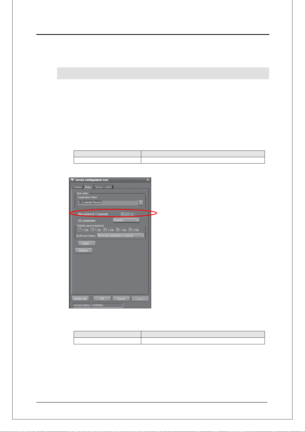
MEDIAEDGE Technical Manual Ver4.10
52
Parameter
Setting Option
TS packet count
[Max number of TS packets] option on Video tab
Parameter
Setting option
TS packet count
[Packet count] in [Video]
[4] Calculate the maximum number of TS packets and RTP packets with the following
formula:
See the “TS packets Optimal Value" section on the "MEDI AEDG E Techni cal Manual Technical References -" for the calculated values.
TSPackets = ((MTU – IP Header Size[20]) x n - UDP Header Size[8]
- RTP Header Size[12] - FEC Header Size[0 or 12 or 28]) / 188
(Example)
With MTU=1500 and FEC Header Size=0 ( FE C d isa bled), either of 7, 15, 23, 31 (n
= 1, 2, 3, 4)
With MTU=1396 and FEC Header Size=12, either of 7, 14, 21, 29 (n = 1, 2, 3, 4)
[5] Specify t he Max number of TS packets.
For MEDIAEDGE Server:
Specify the value with the Server Configuration tool.
n = Ethernet packet count
For MEDIAEDGE-LSB/LEB4/LEB60:
Specify the value in the Local Settings on the Web Console.
Page 53

MEDIAEDGE Technical Manual Ver4.10
53
■
■
III-4-4. Improving Performance with Network Switch Configur ation
When many packet losses occur, you can set t he net work switch QoS to [Strict].
III-4-5. Bandwidth cont rol functions of MEDIAEDGE-LEB4
MEDIAEDGE-LEB4 version 1.3 or later is equipped with bandwidth control functions provided by
means of PSPacer.
PSPacer, a software module that enables accurate bandwidth control and smooth traffic, is
open-source software that runs on Linux, created and released by AIST, Advanced Industrial
Science and Technology.
For more information on PSPacer, see the following pages.
http://www.gridmpi.org/gridtcp.en.jsp
http://www.aist.go.jp/aist_j/aistinfo/aist_today/vol05_09/vol05_09_topics/vol05_09_topics.html
III-4-5-1. Modifying t he bandwidth control set t ings
Open the MEDIAEDGE-LEB4 Web Console, access the [SETTINGS – Local settings –
Distribution] page, and s et a value (in 100 0bp s unit s) to t he maximum value o f [Bandwi dth cont rol].
The value is set to 0 by default, which means that bandwidth control is disa bl ed.
When bandwidth control is enabled, MEDIAEDGE-LEB4 mandatorily sets NIC to 100Mbps
Full-Duplex or lower .
III-4-5-2. Determining the parameters for bandwidth contr ol
To execute distribution wit h certai n encoding p ara meters, open the Web Con sole, acc ess [S t at us –
Full log], and review the valu e of “max rate =”.
This value is the maximum transfer rate for the TS stream that the MEDIAEDGE-LEB4 delivers.
The bandwidth contr ol value can be calculated as follows:
Bandwidth control value = (max rate + 100 to 200 kbps) * (number of streams to deliver
simultaneously) * (x 2 if FEC is enabled)
Normally, the number of the streams that can be delivered simultaneously is 1. To deliver multiple
unicast distributions si mu ltaneously, set the relevant number.
The maximum bandwidth control value is 10Mbps.
If the transfer rate of the stream to be delivered actually exceeds the bandwidth control value,
either of the following proble m s will occur:
- Distribution from the MEDIAEDGE-LEB4 will be delayed, causing problems in playback for
clients.
- The transfer buffer of the MEDIAEDGE-LEB4 will run out, and the distribution operation will
restart.
Page 54

MEDIAEDGE Technical Manual Ver4.10
54
■
■
■
III-5. Tuning Server Performance
III-5-1. Improving Performance with NIC Configuration
Some NICs have hardware s et t ings on the send and receive descriptors.
Increasing these settings may i mprove sending and receiving performance respectiv ely. However,
larger settings use more memory.
Also, changing the flow-c ontrol settings may improve performance.
III-5-2. Improving Perf ormance with Disk Configur ation
When disk performance is low, check the following set t ings.
For single drive:
・ Check if the disk controlle r is set t o DMA transfer.
・ Check if the disk cache is enabled.
For RAID:
・ Check if the cache is enabled.
Note that the Write cache is likely to be set to OFF by default. In that case, you must
change it in the BIOS men u on t he controller.
III-5-3. Setting Process Priority
If packet losses occur when you operate the Server console on the server, this may be because
the CPU load is too large. In that case, prioritizing the stream-server process may solve the
problem.
To modify the settings, open the Server Configuration Tool, select the [Common] tab, and change
the priority settings. To make the settings take effect, restart service (which causes delivery and
recording to temporarily stop).
It is recommended that y ou set the pri ority t o [High]. If you set it to [Realt ime], per formance m ay be
lowered for other reasons.
Page 55

MEDIAEDGE Technical Manual Ver4.10
55
IV.
MEDIAEDGE System Configuration
Page 56
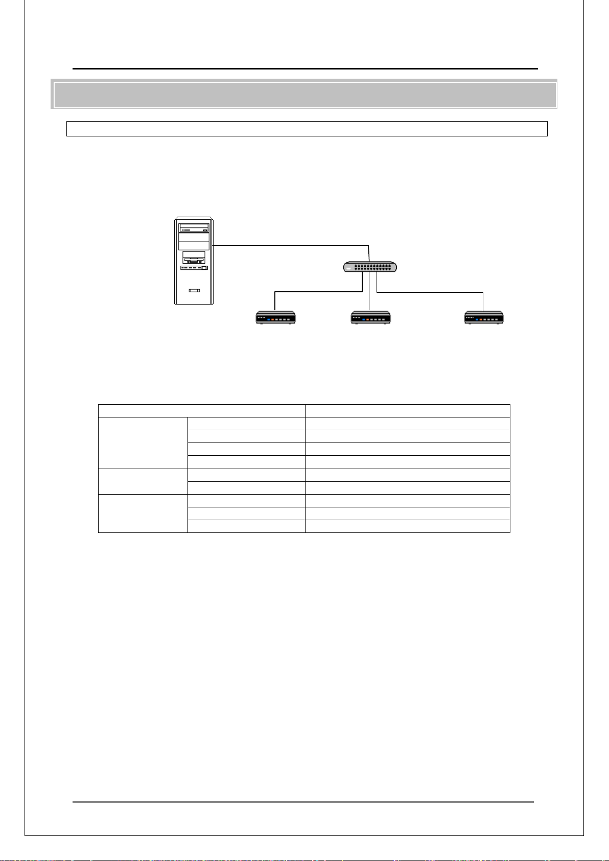
MEDIAEDGE Technical Manual Ver4.10
56
■
Computer name
mediaedge-svr
IP Address
192.168.1.1
Subnet Mask
255.255.255.0
Default Gateway
None
DNS Address
192.168.1.1
DNS
Zone Name
localdomain
Host
mediaedge-svr / 192.168.1.1
Scope
192.168.1.101-192.168.1.200
DNS Server
192.168.1.1
DNS Domain Na me
localdomain
MEDIAEDGE Server
192.168.1.1/24
DB Server
IV-1. Server configuration
IV-1-1. Single Server/ Single Segment Configura t ion
Single server/single segment is a simple configuration consisting of one server mounted with one
NIC. This is the simplest and basic configuration.
System Configuration
Web Server
DHCP Server
DNS Server
Stream Server
STB4
192.168.1.101 / 24
STB4
192.168.1.102 / 24
STB4
192.168.1.103 / 24
System Setup (Example)
MEDIAEDGE Server Setup
NIC
DHCP
Notes on the System Setup
• Using class C IP address is recommended.
• MEDIAEDGE-STB4 will first search for the DHCP server. When it is found, an IP address
will be retrieved.
• If scheduled deli very (m ulti cast ) is used, MEDIAEDGE-STB4 reception limitations must be
considered. When the MEDIAEDGE-STB4 is linked with 100base-TX, up to 60Mbps can be
received. When linked with 1000Base-T, up to 500Mbps can be received.
By using L3 switch, only the stream for the requested channel is delivered to the client,
thereby relieving the netw or k loa d.
Page 57
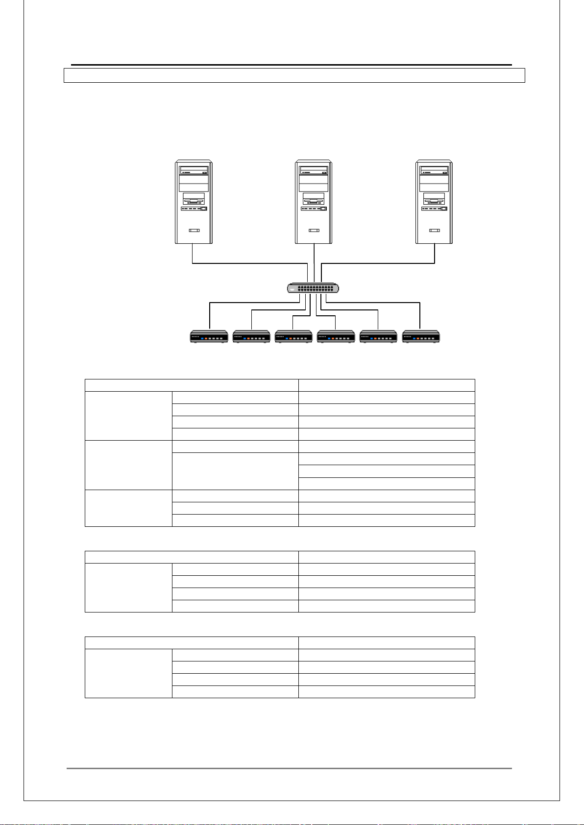
57
■
Computer name
mediaedge-svr01
IP Address
192.168.1.1
Subnet Mask
255.255.255.0
Default Gateway
None
DNS Address
192.168.1.1
Zone Name
localdomain
mediaedge-svr01 / 192.168.1.1
mediaedge-svr02 / 192.168.1.2
mediaedge-svr03 / 192.168.1.3
Scope
192.168.1.101-192.168.1.200
DNS Server
192.168.1.1
DNS Domain Na me
localdomain
Computer name
mediaedge-svr02
IP Address
192.168.1.2
Subnet Mask
255.255.255.0
Default Gateway
None
DNS Address
192.168.1.1
Computer name
mediaedge-svr03
IP Address
192.168.1.3
Subnet Mask
255.255.255.0
Default Gateway
None
DNS Address
192.168.1.1
MEDIAEDGE Server 01
192.168.1.1/24
MEDIAEDGE Server 02
MEDIAEDGE Server 03
192.168.1.2/24
192.168.1.3/24
IV-1-2. Multi Server
System Configuration
Three-server configurat ion:
MEDIAEDGE Technical Manual Ver4.10
DB Server
Web Server
DHCP Server
DNS Server
Stream Server
System Setup (Example)
Stream Server
mediaedge-svr01 (i.e. Database, Menu, D H CP, DNS Servers)
NIC
DNS
Registered Host
Stream Server
DHCP
mediaedge-svr02 (Stream server)
NIC
mediaedge-svr03 (Stream server)
NIC
Page 58
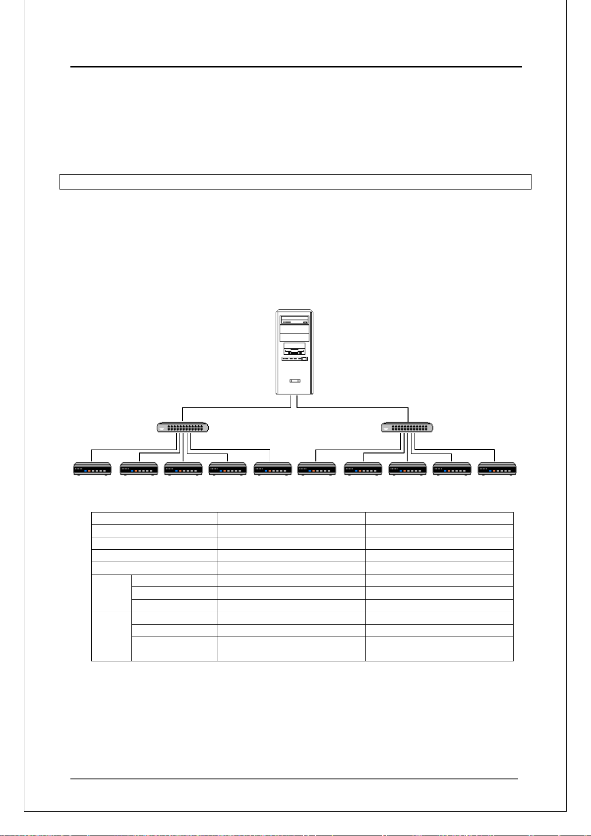
MEDIAEDGE Technical Manual Ver4.10
58
■
NIC1
NIC2
IP Address
192.168.1.1
192.168.2.1
Subnet Mask
255.255.255.0
255.255.255.0
Default Gateway
None
None
DNS Address
192.168.1.1
192.168.2.1
Zone Name
localdomain
localdomain2
Host Name
mediaedge-svr
mediaedge-svr
Host Address
192.168.1.1
192.168.2.1
Scope
192.168.1.101-192.168.1.200
192.168.2.101-192.168.2.200
DNS Server
192.168.1.1
192.168.2.1
DNS Domain
Name
DB Server
MEDIAEDGE Server
192.168.1.1/24
192.168.2.1/24
Notes on System Setup
• Servers other than the first serv er shall be c onfigured as stream servers.
• Host names and IP addresses of all servers shall be registered on the DNS server.
• Use the Server console to register the servers (other than the first one).
• Allow the Database and ActiveX remote access.
IV-1-3. Multi-segment
By using multiple NICs, and dividing the segment of the clients, the delivery performance can be
improved.
System Configuration
System configuration exa mp le w ith ONE server and two NICs.
Web Server
DHCP Server
DNS Server
Stream Server
System Setup (Example)
MEDIAEDGE Server Setup
DNS
DHCP
By setting up two domains on DNS, router (default gateway) in DHCP scope options will not
need to be specified.
localdomain localdomain2
Page 59
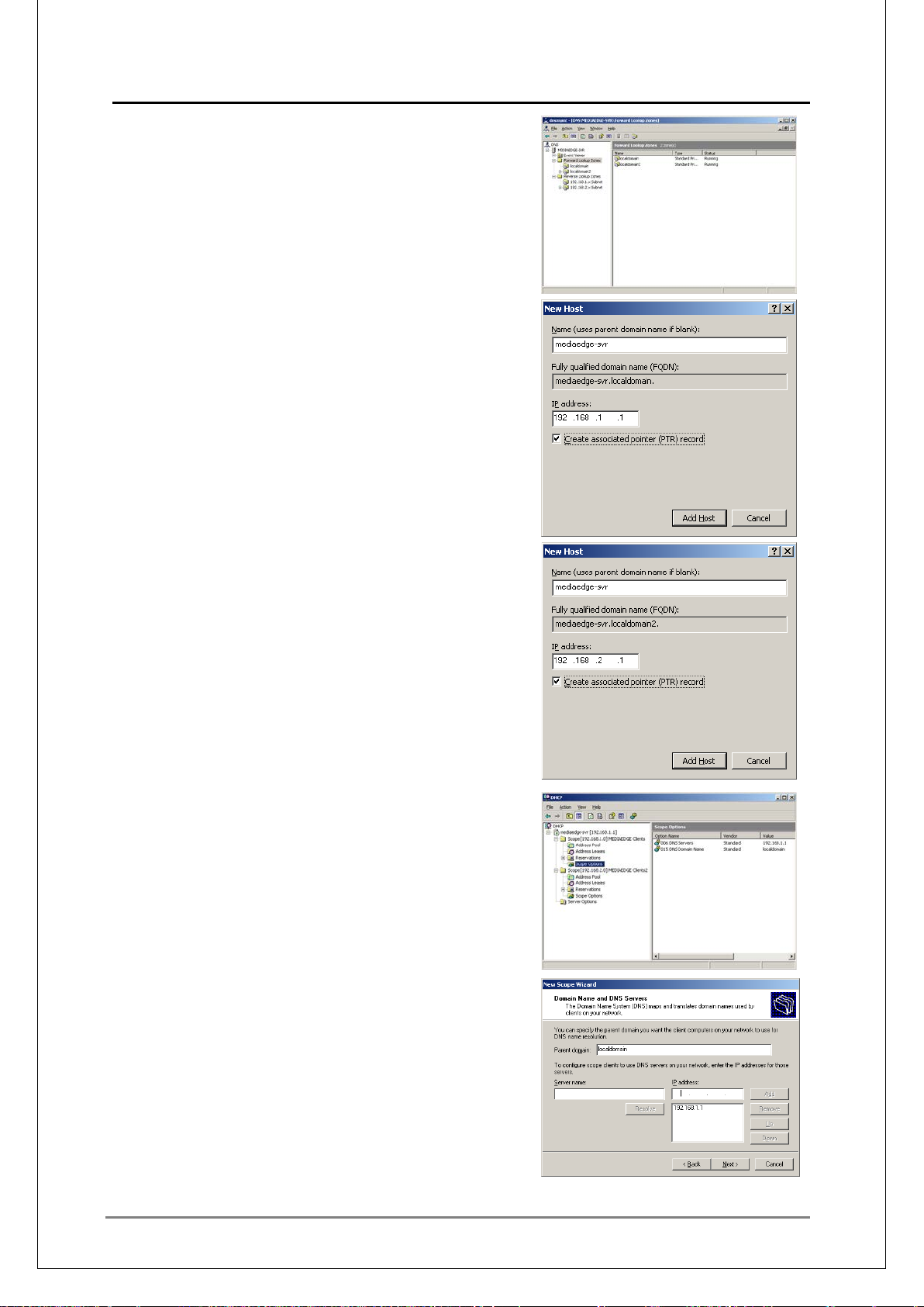
59
System Setup
Two zones will be setup on DNS:
Forward lookup zone:
localdomain, localdomain2
Reverse lookup zone:
192.168.1.x, 192.168.2. x
Add a host to the "localdoma in" zone.
Add a host to "localdomai n2" zone.
Create DHCP scope.
MEDIAEDGE Technical Manual Ver4.10
Page 60

MEDIAEDGE Technical Manual Ver4.10
60
■
IV-1-4. How to change the computer name of the server where MEDIAEDGE-SVS4 is
installed
1. Export the current registration information
Use the Registration Information Export Tool to expor t t he cur r ent r egistration information from the
database.
Check the following option s:
- Export all definitions in source server
- Delete all definitions in installation server
- Copy files required for installation
Uncheck the following opti on:
- Copy MPEG files
Click [Start Exporting] to export the registration information to a specified folder.
* Note that all contents of the specified folder will be deleted.
2. Change the com puter name
Right-click [Computer], choose [Properties] – [Change], change the computer name, and restart
the server.
3. Change the DNS registration
When a DNS server is used, choose [Computer Management] – [Roll]-[DNS server] on the DNS
server , delete r egistration s for the old s erver name, and add registr ations for t he new server name.
4. Change the database server name
If the database is installed on a server whose name has been changed, run the Server
Configuration Tool on the server, choose [Database] – [Computer name], and change the name to
the new computer name.
If the sample menu is used, open “C:\MediaEdge\Sample\global.asa” with a text editor and
change
DBServerName = "<old computer name>"
to
DBServerName = "<new computer name>"
5. Update the registration information
Open the folder where the r egistr at ion information is exported (see step 1) and run Cont I nst .exe.
The information registered on the database will be updated to that for t he new server name.
6. Change the sample menu
When the Static menu in the sample menus is used, open the HTML file and the SMIL file stored
under "C:\MediaEdge\Sample\STB4\static\" with a text editor and change the strings of the old
server name in the URL to those of the new server name.
Sample menu folder for other clients:
MEDIAEDGE-STB4:
C:\Mediaedge\Sample\STB4\Static
MEDIAEDGE-SWT4:
C:\Mediaedge\Sample\SWT4\English
Page 61
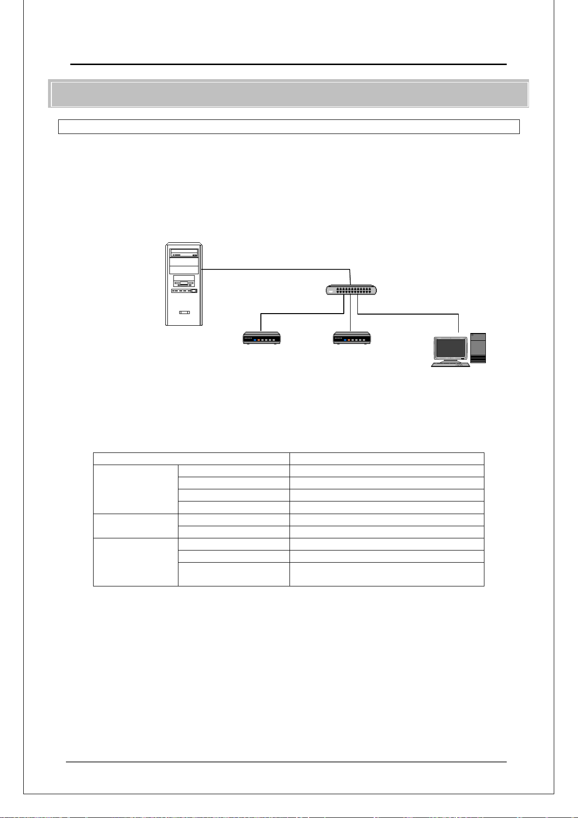
MEDIAEDGE Technical Manual Ver4.10
61
■
Computer name
mediaedge-svr
IP Address
192.168.1.1
Subnet Mask
255.255.255.0
Default Gateway
None
DNS Address
192.168.1.1
DNS
Zone Name
localdomain
Host Name
mediaedge-svr / 192.168.1.1
Scope
192.168.1.101-192.168.1.200
DNS Server
192.168.1.1
DNS Domain
Name
MEDIAEDGE Server
192.168.1.1/24
STB4
STB4
SWT4
IV-2. Client Configur ati on
IV-2-1. Mixed Configurat ion wit h MEDIAEDGE-STB4/SWT4
System configuration example with mixed configuration of MEDIAEDGE-STB4/SWT4 in single
server, single segment.
System Configuration
DB Server
Web Server
DHCP Server
DNS Server
Stream Server
192.168.1.101 / 24
System Setup (Example)
MEDIAEDGE Server Setup
NIC
DHCP
Notes on the System Setup
• Using class C IP address is recommended.
192.168.1.102 / 24
192.168.1.103 / 24
localdomain
• MEDIAEDGE-STB4/SWT4 will first search for the DHCP server. When it is found, an IP
address will be retrieved.
Page 62
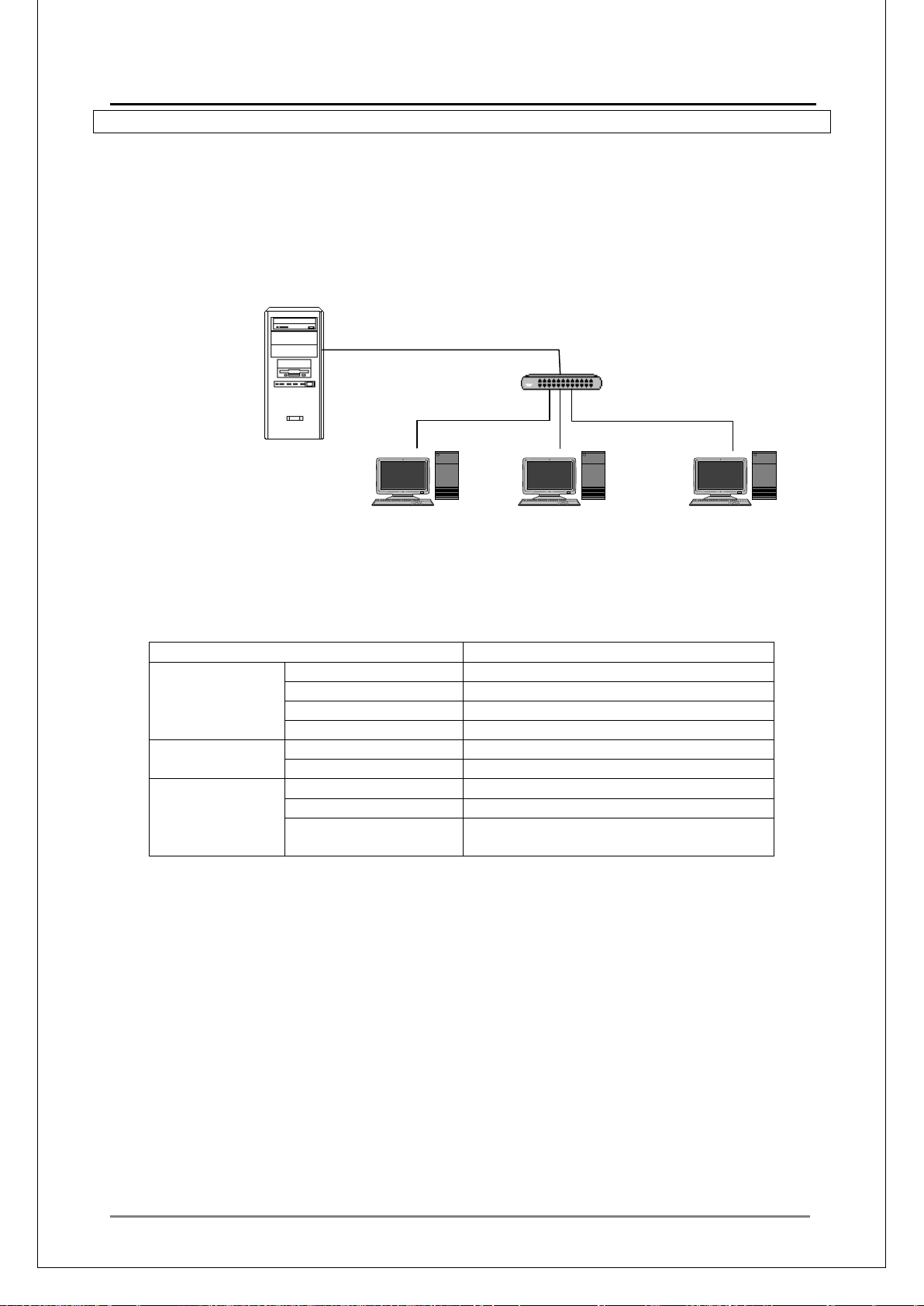
MEDIAEDGE Technical Manual Ver4.10
62
■
Computer name
mediaedge-svr
IP Address
192.168.1.1
Subnet Mask
255.255.255.0
Default Gateway
None
DNS Address
192.168.1.1
DNS
Zone Name
localdomain
Host Name
mediaedge-svr / 192.168.1.1
Scope
192.168.1.101-192.168.1.200
DNS Server
192.168.1.1
DNS Domain
Name
MEDIAEDGE Server
192.168.1.1/24
DB Server
IV-2-2. Configuration for MEDIAEDGE-DAS4
System configuration example where the MEDIAEDGE-SWT4 is authenticated via network with a
SWT4 authentication server (MEDIAEDGE-DAS4 added to a single MEDIAEDGE Server.
System Configuration
Web Server
DHCP Server
DNS Server
Stream Server
DAS4 Server
SWT4
192.168.1.101 / 24
SWT4
192.168.1.102 / 24
SWT4
192.168.1.103 / 24
System Setup (Example)
MEDIAEDGE Server Setup
NIC
DHCP
localdomain
Notes on the System Setup
• Using class C IP address is recommended.
• MEDIAEDGE-SWT4 will first search for the DHCP server. W hen it is f ound, an IP address
will be retrieved.
• Dongle is not required on the client where the MEDIAEDGE-SWT4 is installed. The
authentication server set t i ngs will be used.
Page 63
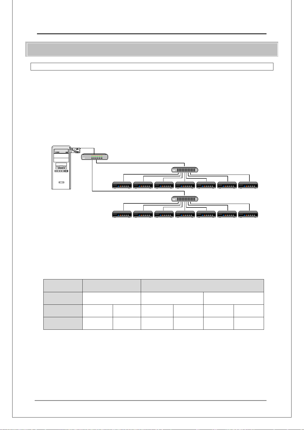
MEDIAEDGE Technical Manual Ver4.10
63
■
IGMP Function
Not Used
Multicast
address
Video
(Client)
Amount
received
DB Server
L3 Switching HUB
L2 Switching HUB
L2 Switching HUB
192.168.1.1/24
192.168.1.254/24
STB4: 192.168.2.101~ /24
IV-3. Multicast
IV-3-1. Controlling Multicast Streams by IGMP
In a network with only one switching hub (L2 switch), all multicast streams will be delivered to all
the clients during scheduled deliveries. When the clients receive packets larger than their
reception capacity, problems including distorted images and images not being played back, will
occur.
By configuring the network with IGMP version 2 compatible router or level 3 switch, and IGMP
snooping capable layer 2 switch, only requested multicast stream will be delivered to each client.
System Configuration
MEDIAEDGE Server
Web Ser v er
DHCP Server
DNS Server
Stream Server
(IGMPv2 Compatible)
(IGMPv2 Snoop Feature Compatible)
(IGMPv2 Snoop Feature Compatible)
In this configuration, the IGMP version 2 capable router has two responsibilities, one as an
IGMP querier and an ot her to stop unknown multicast packet s.
IGMP snooping featur e cont rols each mu lticast addr ess, ther efore assig ning dif ferent m ulticast
addresses to each channel will be very effective. Wh en the multica st address is t he same and
there are multiple channels with different ports, they will be treated as one multicast group.
Even when a client requests reception for one of the streams in this group, all the streams in
that group will be delivere d t o t he c lient.
・In the case where 8 channels are c r eat ed, and contents in 10Mbps are deliv er ed:
IGMP Function Used
--- Universal Unique
Playing Stopped Playing Stopped Playing Stopped
80Mbps 80Mbps 80Mbps 0Mbps 10Mbps 0Mbps
To make full use of the IGMP function, specify unique addresses for the Multicast address of
channels.
Page 64
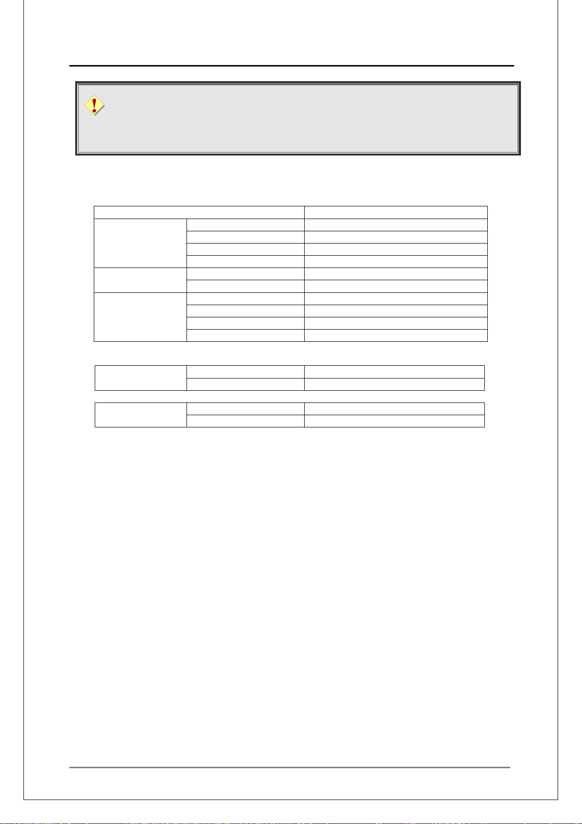
MEDIAEDGE Technical Manual Ver4.10
64
Computer name
mediaedge-svr
IP Address
192.168.1.1
Subnet Mask
255.255.255.0
Default Gateway
192.168.1.254
DNS Address
192.168.1.1
DNS
Zone Name
localdomain
Host
mediaedge-svr / 192.168.1.1
Scope
192.168.2.101-192.168.2.200
DNS Server
192.168.1.1
DNS Domain Na me
localdomain
Default Gateway
192.168.2.254
LAN (on the
server side)
IP Address
192.168.1.254
Subnet Mask
255.255.255.0
LAN (on the client
side)
IP Address
192.168.2.254
Subnet Mask
255.255.255.0
IGMP compati bl e MEDIAEDGE-STB4/STB4H/HDMA-4100
MEDIAEDGE-STB4 supports I GMP versions 2 & 3. The version operated by default will
differ depending on the multicast address to allow normal operations of network devices
compatible to IGMP version 2. IGMPv3 is given priority for Source-Specific Multicast
(232.0.0.0/8), while IGM Pv2 is prioritized in other cases.
System Setup (Example)
MEDIAEDGE Server Setup
NIC
DHCP
Router (L3 switch) on the server side
Router (L3 switch) on the client side
Notes on the System Setup
• Enable IGMP function of the L3 switch or the rout er.
• Enable IGMP snooping function of L2 switch.
• Enable IGMP fast-leave function of L2 sw itch.
• When th e DHCP serv er and DHCP client are on se par ate segment s, DHCP relay function i s
required on L3 switch or the router.
Page 65
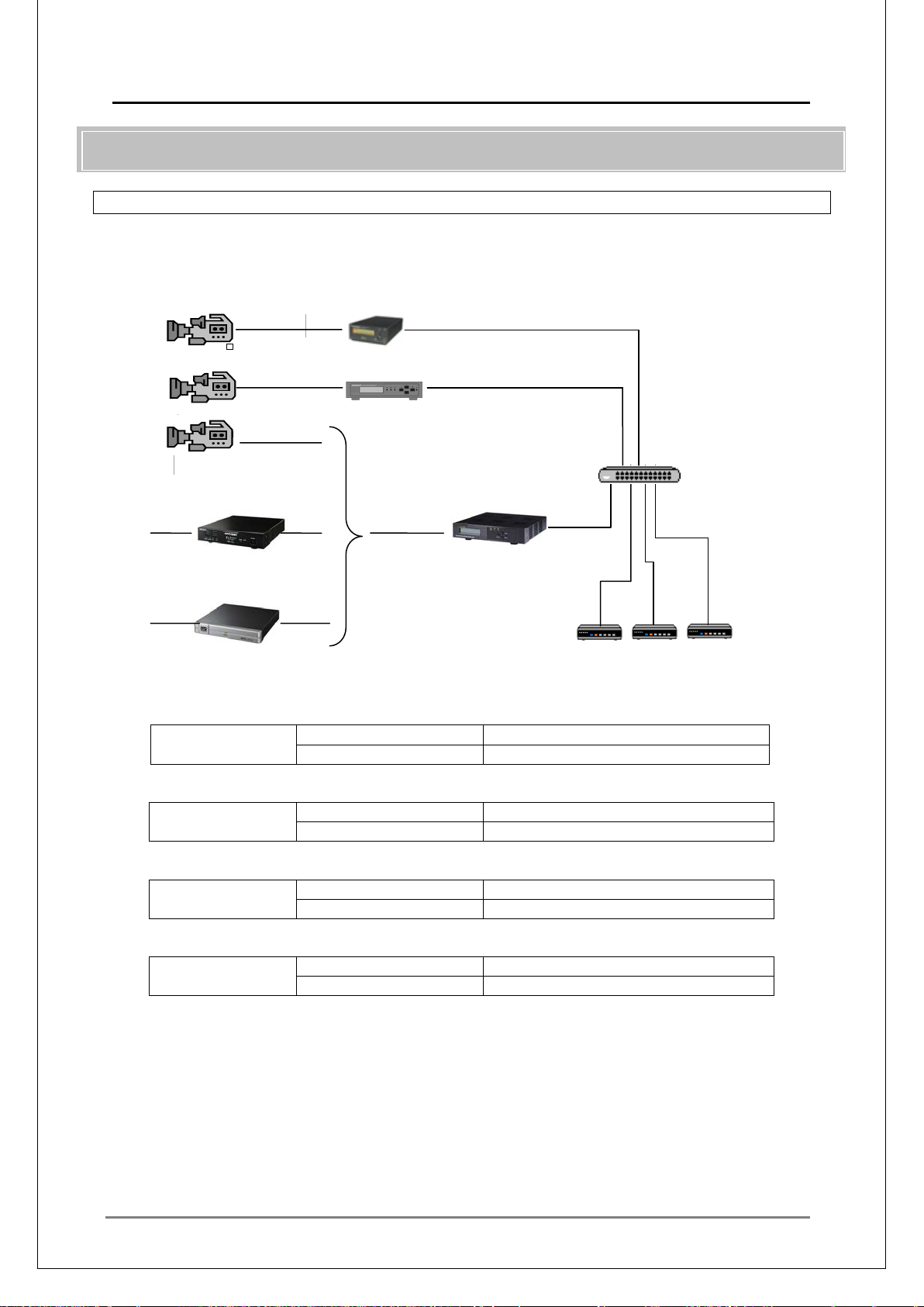
MEDIAEDGE Technical Manual Ver4.10
65
■
IP Address
192.168.1.101 – 192.168.1.103
Subnet Mask
255.255.255.0
IP Address
192.168.1.21
Subnet Mask
255.255.255.0
IP Address
192.168.1.31
Subnet Mask
255.255.255.0
IP Address
192.168.1.11
Subnet Mask
255.255.255.0
Video camera
Video camera
STB4
STB4
STB4
IV-4. Live Delivery
IV-4-1. Configuration for direct delivery from MEDIAEDGE-LSB/LEB4/LEB60 to clients
This is a simple configuration that c onsists only units, without using a ser ver.
While there are operational l i mitations, it's inexpensive and is tough to mech anical failure.
System Configuration
MEDIAEDGE-LEB60
MEDIAEDGE-LEB4
Switching HUB
HDV camera
HD-SDI
ADVC-HDM1
HDMI
ADVC-HD50
System Setup (Example)
MEDIAEDGE-STB4 Setup
NIC
MEDIAEDGE-LSB Setup
NIC
MEDIAEDGE-LEB4 Setup
NIC
MEDIAEDGE-LEB60 Setup
HDV
MEDIAEDGE-LSB
NIC
Notes on the System Setup
• W ithout using the MEDIAEDGE-LSB/LEB4/LEB60 menu, perform channel settings on the
clients (MEDIAEDGE-STB4) by changing the VOD setting to t he channel mode.
• The length of the IEEE1394 cables to be used for MEDIAEDGE-LSB input is standalized to
be up to 4.5m.
• In unicast delivery from MEDIAEDGE-LSB/LEB60, a video from a MEDIAEDGE-LSB/
LEB60 can only be viewed on a client.
• To view video sent from MEDIAEDGE-LSB/LEB60 on multiple clients, execute multicast
delivery from the MEDIAEDGE-LSB/LEB60.
Page 66
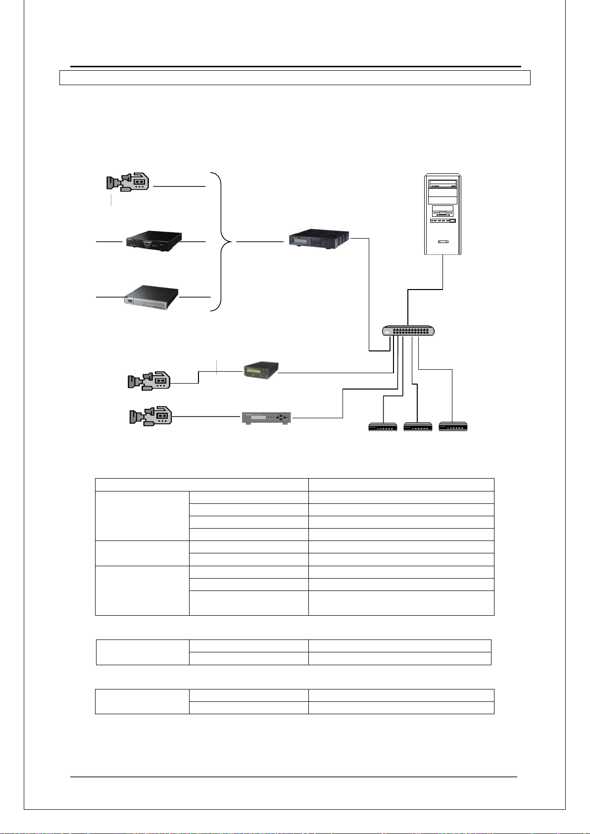
MEDIAEDGE Technical Manual Ver4.10
66
■
Computer name
mediaedge-svr
IP Address
192.168.1.1
Subnet Mask
255.255.255.0
Default Gateway
None
DNS Address
192.168.1.1
DNS
Zone Name
localdomain
Registered Host
mediaedge-svr / 192.168.1.1
Scope
192.168.1.100 -192.168.1.200
DNS Server
192.168.1.1
Name
localdomain
IP Address
DHCP (192.168.1.101 - )
Subnet Mask
DHCP
IP Address
192.168.1.11
Subnet Mask
255.255.255.0
MEDIAEDGE Serv e r
Video camera
Video camera
STB4
STB4
STB4
IV-4-2. Configuration for relay delivery by server
This is a configuration where the MEDIAEDGE Server receives a video source sent from a
MEDIAEDGE-LSB/LEB4/LEB60, and then relays it to clients.
Flexible operations, inc luding choosing video from the menu, can be rea liz ed.
System Configuration
HDV camera
HD-SDI
ADVC-HDM1
HDMI
ADVC-HD50
System Setup (Example)
MEDIAEDGE Server Setup
NIC
HDV
MEDIAEDGE-LSB
Switching HUB
MEDIAEDGE-LEB60
MEDIAEDGE-LEB4
DHCP
MEDIAEDGE-STB4 Set up
NIC
MEDIAEDGE-LEB60 Setup
NIC
DNS Domain
Page 67
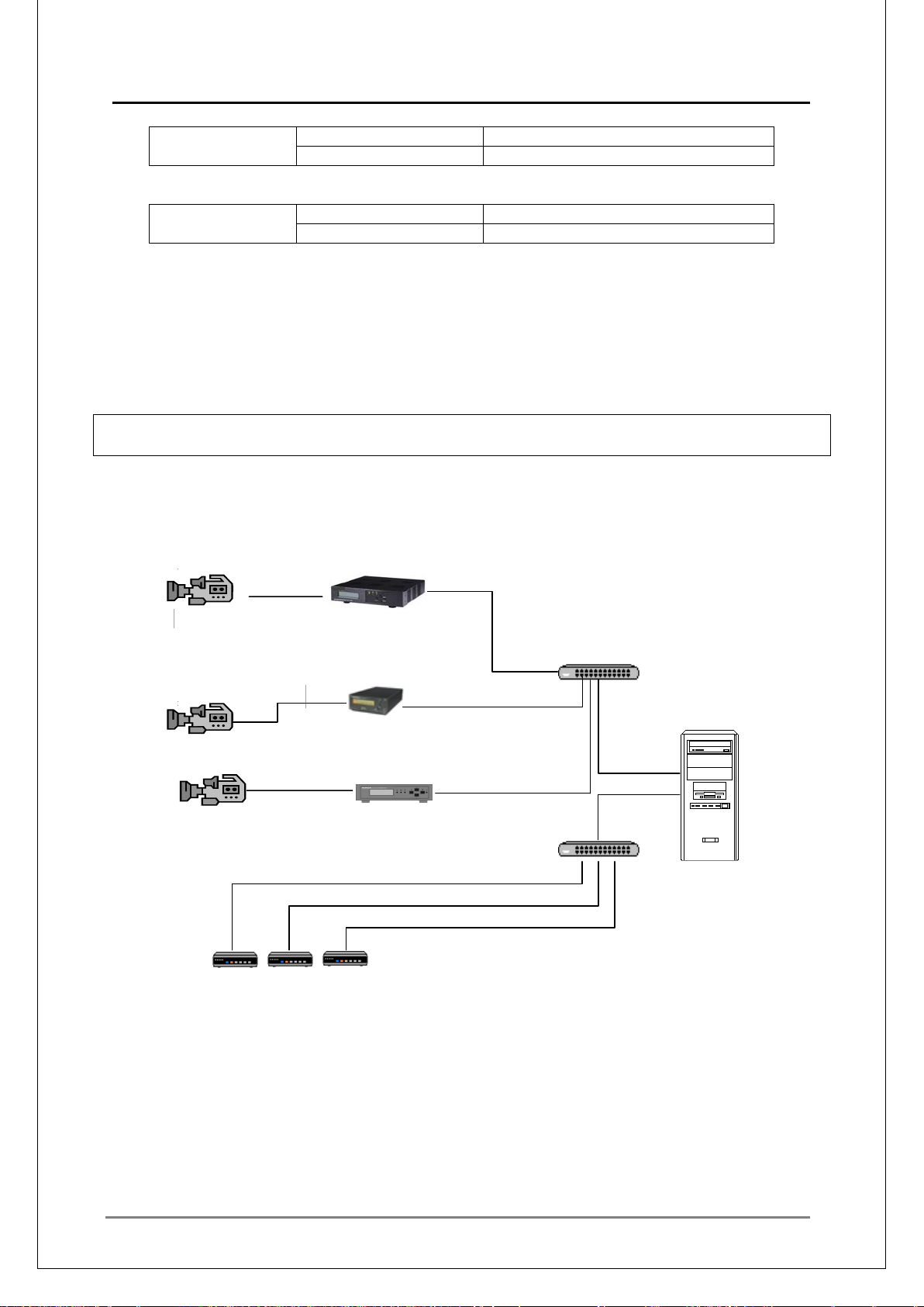
MEDIAEDGE Technical Manual Ver4.10
67
IP Address
192.168.1.21
Subnet Mask
255.255.255.0
IP Address
192.168.1.31
Subnet Mask
255.255.255.0
■
MEDIAEDGE Serv e r
Video camera
STB4
STB4
STB4
MEDIAEDGE-LSB Setup
NIC
MEDIAEDGE-LEB4 Setup
NIC
Notes on the System Setup
• The length of the IEEE1394 cables to be used for MEDIAEDGE-LSB input is standalized to
be up to 4.5m.
• Register MEDIAEDGE-LSB/LEB4/LE B60 as relay content.
• By requesting a MEDIAEDGE relay cont ent from a client, relayed video can be viewed.
IV-4-3. Configuration where MEDIAEDGE-LSB/LEB4/LEB60 and clients are divided into
segments
This is a configuration where video source and the clients are divided into segments to distribute
the network load.
System Configuration
HDV
HDV camera
Video camera
MEDIAEDGE-LSB
Switching HUB
MEDIAEDGE-LEB60
MEDIAEDGE-LEB4
Switching HUB
Page 68

MEDIAEDGE Technical Manual Ver4.10
68
NIC1 (LSB/LEB4/LEB60 side)
NIC2 (STB side)
IP Address
192.168.1.1
192.168.2.1
Subnet Mask
255.255.255.0
255.255.255.0
Default Gateway
None
None
DNS Address
192.168.1.1
192.168.2.1
Zone Name
localdomain
localdomain2
Host Name
mediaedge-svr
mediaedge-svr
Host Address
192.168.1.1
192.168.2.1
Scope
192.168.2.101-192.168.2.200
DNS Server
192.168.2.1
DNS Domain
Name
IP Address
DHCP (192.168.2.101 - )
Subnet Mask
DHCP
IP Address
192.168.1.11
Subnet Mask
255.255.255.0
IP Address
192.168.1.21
Subnet Mask
255.255.255.0
IP Address
192.168.1.31
Subnet Mask
255.255.255.0
System Setup (Example)
MEDIAEDGE Server Setup
DNS
DHCP
localdomain2
MEDIAEDGE-STB4 Setup
NIC
MEDIAEDGE-LEB60 Setup
NIC
MEDIAEDGE-LSB Setup
NIC
MEDIAEDGE-LEB4 Setup
NIC
Notes on the System Setup
• MEDIAEDGE-LSB/LEB4/LEB60 uses a static IP.
• Register MEDIAEDGE-LSB/LEB4/LEB60 as relay contents.
• By requesting a MEDIAEDGE relay content from a client, relayed video can be v iewed.
Page 69
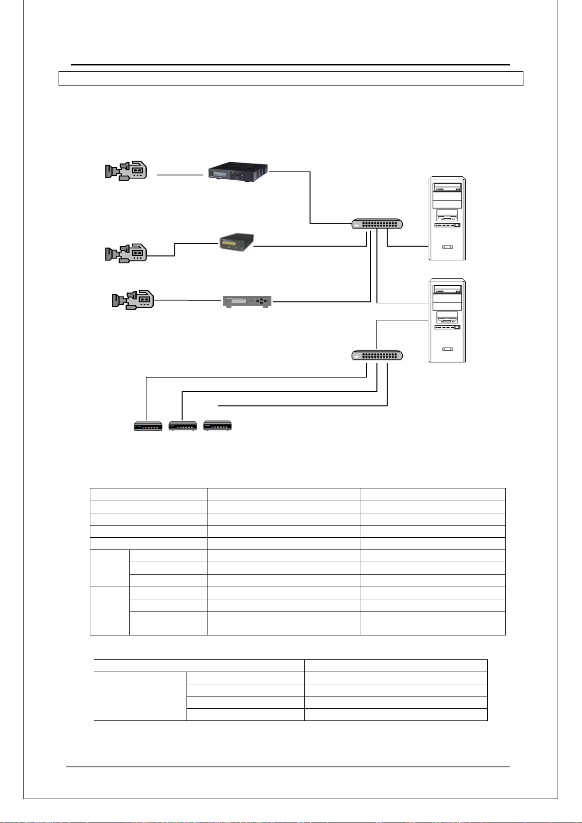
MEDIAEDGE Technical Manual Ver4.10
69
■
NIC1 (LSB/LEB4/LEB60 side)
NIC2 (STB side)
IP Address
192.168.1.1
192.168.2.1
Subnet Mask
255.255.255.0
255.255.255.0
Default Gateway
None
None
DNS Address
192.168.1.1
192.168.2.1
Zone Name
localdomain
localdomain2
Host Name
mediaedge-svr
mediaedge-svr
Host Address
192.168.1.1
192.168.2.1
Scope
192.168.2.101-192.168.2.200
DNS Server
192.168.2.1
DNS Domain
Name
Computer name
mediaedge-svrbk
IP Address
192.168.1.2
Subnet Mask
255.255.255.0
Default Gateway
None
DNS Address
192.168.1.1
MEDIAEDGE SVR BK
Video camera
MEDIAEDGE-SVR
IV-4-4. MEDIAEDGE-LSB/LEB4/LEB60 multicast delivery configuration
This is a configuration to execute multicast delivery from MEDIAEDGE-LSB/LEB4/LEB60, and to
record data by 2 servers for redundancy. D ata delivery to clients is executed by a single server.
System Configuration
HDV
HDV camera
Video camera
STB4 STB4 STB4
MEDIAEDGE-LSB
MEDIAEDGE-LEB60
MEDIAEDGE-LEB4
System Setup (Example)
Primary MEDIAEDGE Server (MEDIAEDGE-SVR) Setup
Switching HUB
Switching HUB
DNS
DHCP
Sub MEDIAEDGE Server (MEDIAEDGE-SVRBK) Setup
localdomain2
NIC
Page 70

MEDIAEDGE Technical Manual Ver4.10
70
IP Address
DHCP (192.168.2.101 - )
Subnet Mask
DHCP
IP Address
192.168.1.11
Subnet Mask
255.255.255.0
IP Address
192.168.1.21
Subnet Mask
255.255.255.0
IP Address
192.168.1.31
Subnet Mask
255.255.255.0
MEDIAEDGE-STB4 Setup
NIC
MEDIAEDGE-LEB60 Setup
NIC
MEDIAEDGE-LSB Setup
NIC
MEDIAEDGE-LEB4 Setup
NIC
Notes on the System Setup
• MEDIAEDGE-LSB/LEB4/LEB60 uses a static IP.
• Execute multicast delivery from MEDIAEDGE-LSB/LEB4/LEB60.
• Register MEDIAEDGE-LSB/LEB4/LEB60 as relay contents to the primary/sub
MEDIAEDGE Servers.
• Function to execute recording operations on primary/sub servers simultaneously, such as
synchronization of the schedu le dat a, simultaneous input of the external trigger, is required.
Page 71
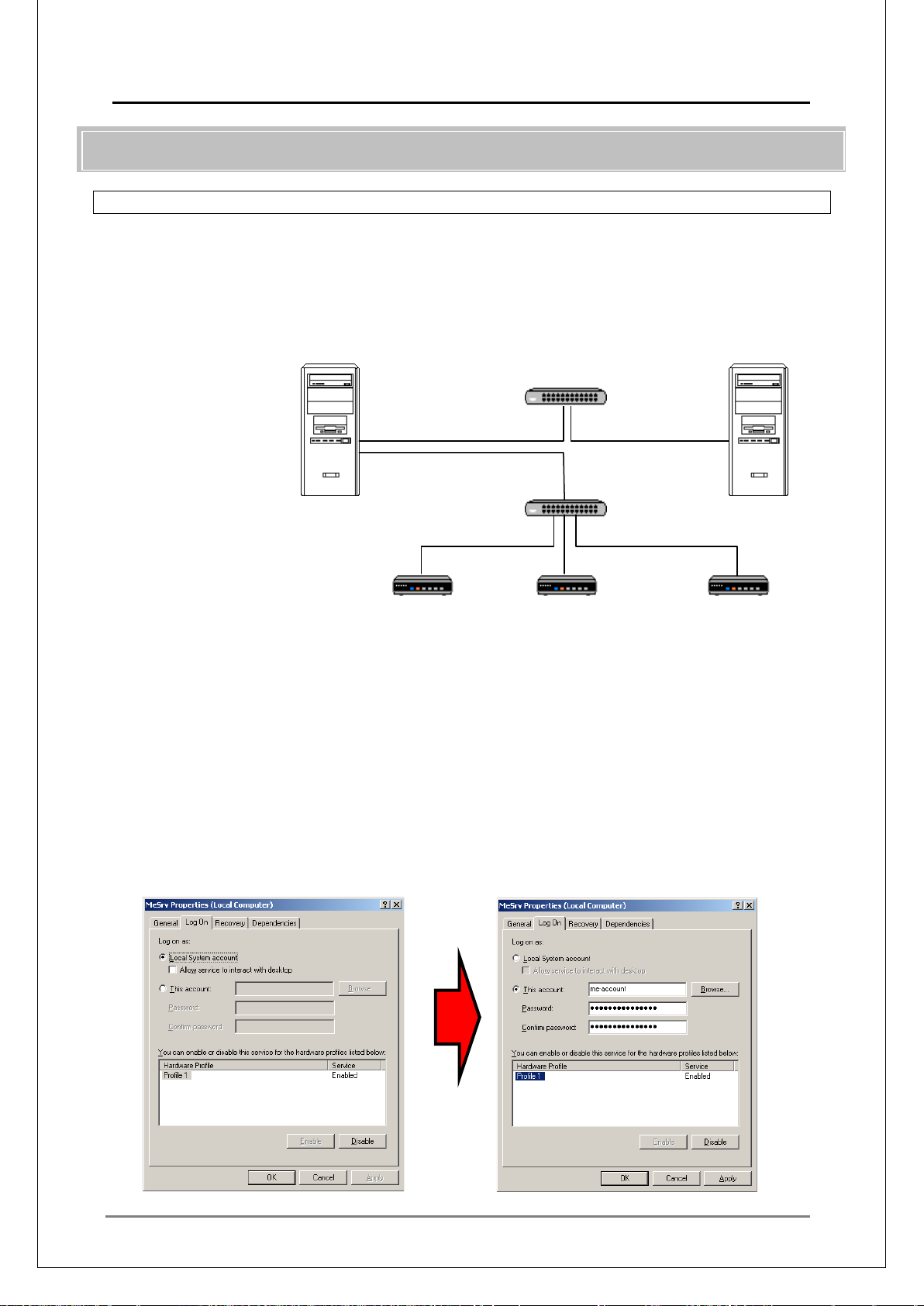
MEDIAEDGE Technical Manual Ver4.10
71
■
MEDIAEDGE Server
file-svr
192.168.1.1/24
192.168.100.2/24
DB Server
IV-5. Using NAS
IV-5-1. Configuration wi th NAS
This is a configuration wh er e MPEG files are stored in another server (NAS).
System Configuration
192.168.100.1/24
Web Ser v er
DHCP Server
DNS Server
Stream Server
STB4
192.168.1.101 / 24
STB4
192.168.1.102 / 24
STB4
192.168.1.103 / 24
Notes on system setup
File server and MEDIAEDGE-STB4 are placed on different network segments each other,
in order to distribute the n et w or k loa d.
Create a single Windows account on both the stream server and the file server.
Change the log-on account for the Windows servic e of the MEDIAEDGE.
Specify the file by a UNC path.
Setup Example
Change the Windows service (MeSrv) for the MEDIAEDGE.
Specify an account that can access both stream server and file server.
Page 72
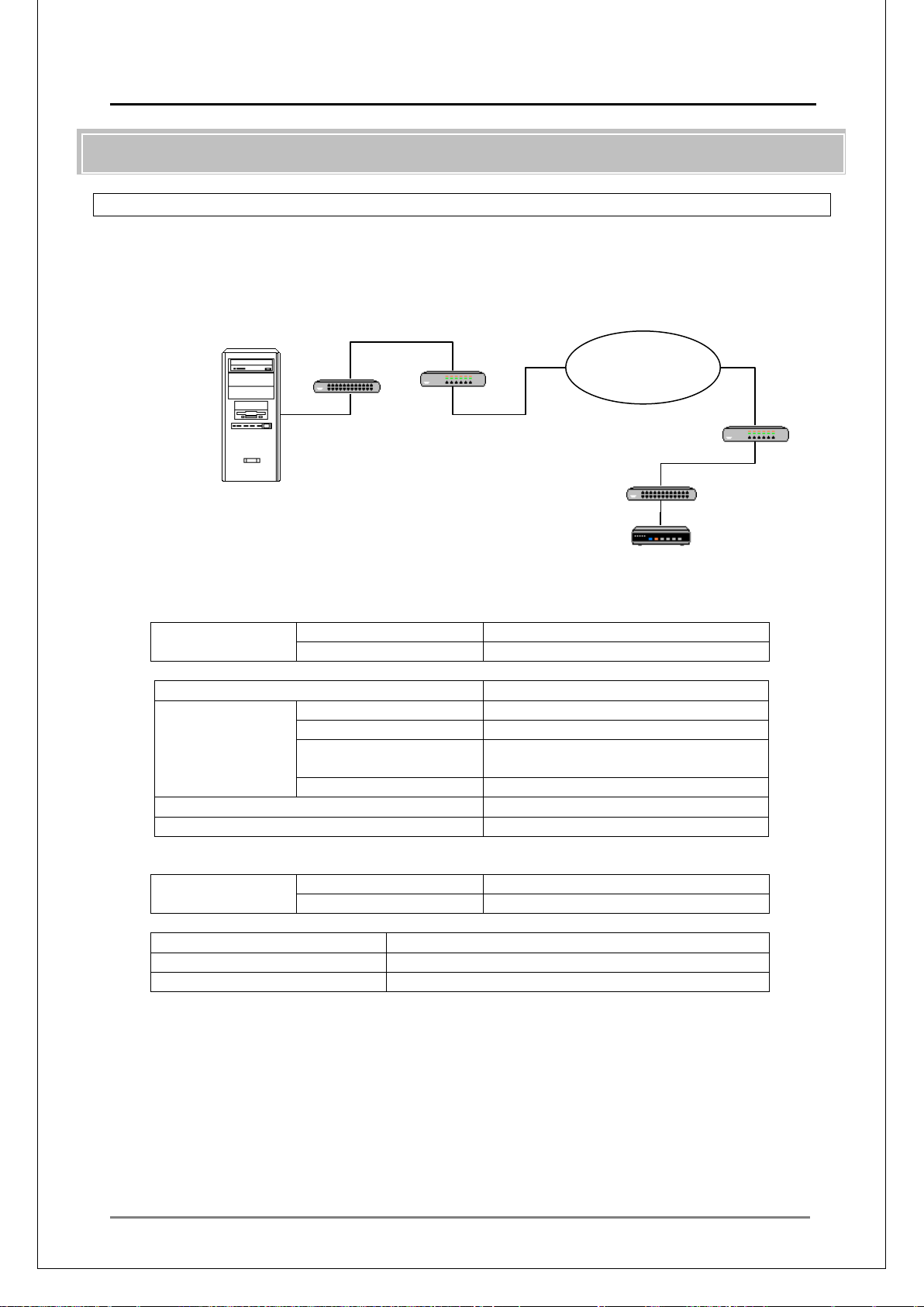
MEDIAEDGE Technical Manual Ver4.10
72
■
LAN
IP Address
192.168.1.254
Subnet Mask
255.255.255.0
Computer name
mediaedge-svr
IP Address
192.168.1.1
Subnet Mask
255.255.255.0
192.168.1.254
(IP address of the router)
DNS Address
None
DNS
None
DHCP
None
LAN
(client side)
IP Address
192.168.2.254
Subnet Mask
255.255.255.0
IP Address
192.168.2.101
Subnet Mask
255.255.255.0
Default Gateway
192.168.2.254 (IP address of the router)
MEDIAEDGE Server
VPN router
Switching hub
VPN router
Switching hub
STB4 192.168.2.101/24
192.168.1.1/24
192.168.1.254
Wide Area IP
IV-6. Using VPN
IV-6-1. VPN connection bet wee n ser ver and clients (Remote delivery )
This is a configuration with a server and clients connected remotely by VPN connection.
System Configuration
Network
192.168.2.254
System Setup (Example)
Router (server side)
(server side)
MEDIAEDGE-SVR Server
NIC
Default Gateway
Router (client side)
MEDIAEDGE-STB4 Setup
Notes on the System Setup
• DHCP server cannot be used via VPN conn ect ion
• Since DHCP cannot be used, clients n eed t o be setup individually
• Use IP address (i.e. 192.168.1.1) in the place of the server name since DNS is not used
• Using the standard settings, there may be times where the VPN transfer speed becomes
insufficient and videos cannot be correctly played back. In this case, UDP packet lengths
and Number of TS packets may need to be adjusted. See "■ III-4-3 TS Packets" for how to
modify the settings.
Page 73
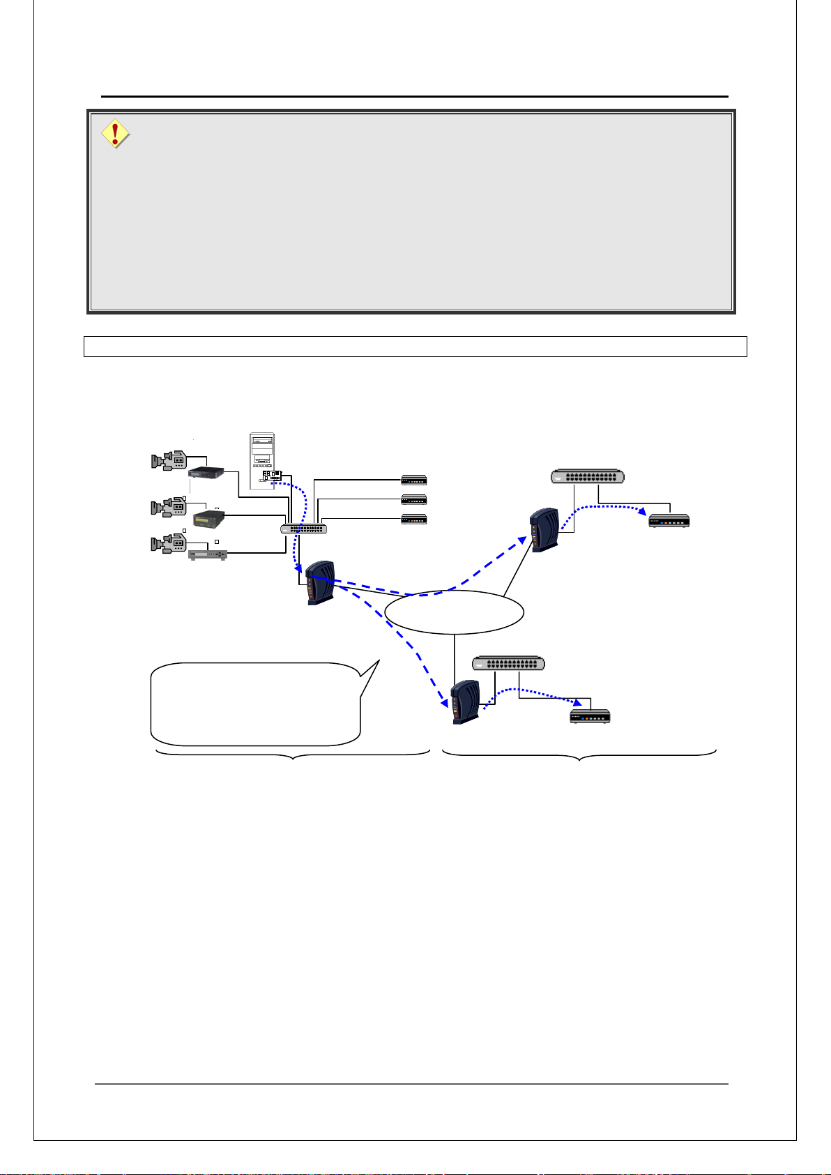
MEDIAEDGE Technical Manual Ver4.10
73
■
Multicast
Wide Area IP
Network
VPN
VPN
Router
VPN
Router
Unicast
Unicast
Multicast
Multicast
Multicast data will be capsulated by
function of the
Number of TS packets
Take the fiber-access network which NTT provides in Japan, for example. B y a d ju sti ng the
number of TS packets to 30, the MTU to 1396, 3 MPEG2 channels 4Mbps could be
delivered (in file delivery).
However , this do es not mean t he abov e set tin g examp le can w or k in any VPN connect ions ,
the transfer situation may get worse.
Also, note that the deliverable stream rate depends largely on the network service, line
status or the VPN router c apabilities.
See the "MEDIAEDG E Technica l Manual - Technical Re ferences -".
IV-6-2. VPN connectio n of MEDIAEDGE-LSB/LEB4/LEB60, Server and Clients (Remote)
Combination with a server (With a server installed on the sender’s side)
Using a Wide Area IP Network and VPN with IPsec, video can be delivered to the clients
installed in each area.
LSB
MEDIAEDGE Server
STB
Switching HUB
LEB60
LEB4
STB4
Switching HUB
the layer 2 tunneling
router before delivering in unicast.
Sender
Router
STB4
Receiver
Page 74
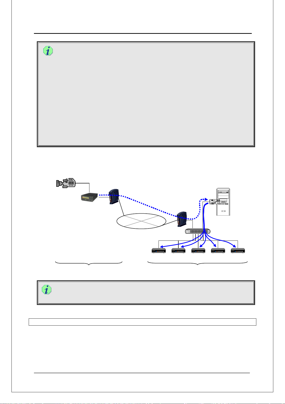
MEDIAEDGE Technical Manual Ver4.10
74
■
Router
LEB
Video
Camera
Switching HUB
STB4
STB4
STB4
STB4
STB4
VPN
Wide Area IP
Network
Unicast
Unicast/Multicast
Multicast (schedule delivery) video delivery
Generally, a multicast stream can’t be delivered in a Wide Ar ea I P Network, therefore, by
utilizing the layer 2 tunnelling function, the multicast data is delivered as unicast data
within the Wide Area IP Network, wrapped in another packet header (capsulat ion).
In this case, if there are multiple receivers, the multicast packets are copied as many
times as there are rece iv er s in t he router of the sender, before delivering them as unicast
to each client.
The delivered unicast data will be reverted to multicast data in the router of the receiver
before delivering to each client.
Therefore, the line which connects the sending location to the Wide Area IP Network has
to have as wide bandwidth as [the maximum bitrate x number of the receiving locations].
If multiple clients are used in each receiving location, the multicast could be utilized to its
full extent.
In the above example, if there is only one client in a receiving location, the number of
required bands to connect the sending location to the Wide Area IP Network is the same
as that for unicast, and the advantages of multicast are few. Since the data is sent as
unicast, wrapped in another packet header (capsulat ion), the transfer will be inefficient.
Combination w it h a ser ver (With a server installed on the receiver’s side)
Using MEDIAEDGE-LSB/LEB4/LEB60, which is a small unit whose setup location is
hardly limited by its size, and the Wide Area IP Network and VPN with IPsec, video can
be delivered to the clients installed in each area.
Sender
VPN
Router
MEDIAEDGE Server
NIC
Receiver
As the video from the MEDIAEDGE-LSB/LEB4/LEB60 will be redelivered using the relay
function of the MEDIAEDGE, data will be delivered to the Wide Area IP Network as
uncast.
IV-6-3. Connection via NAT/NAPT
MEDIAEDGE does not support the connection via NAT/NAPT.
Video stream cannot be receiv ed under the env iron ment w here any of the cli ent , live unit or server
can only be accessed via NAT/NAPT.
In such cases, use a VPN router, and establish a VPN connection.
Page 75
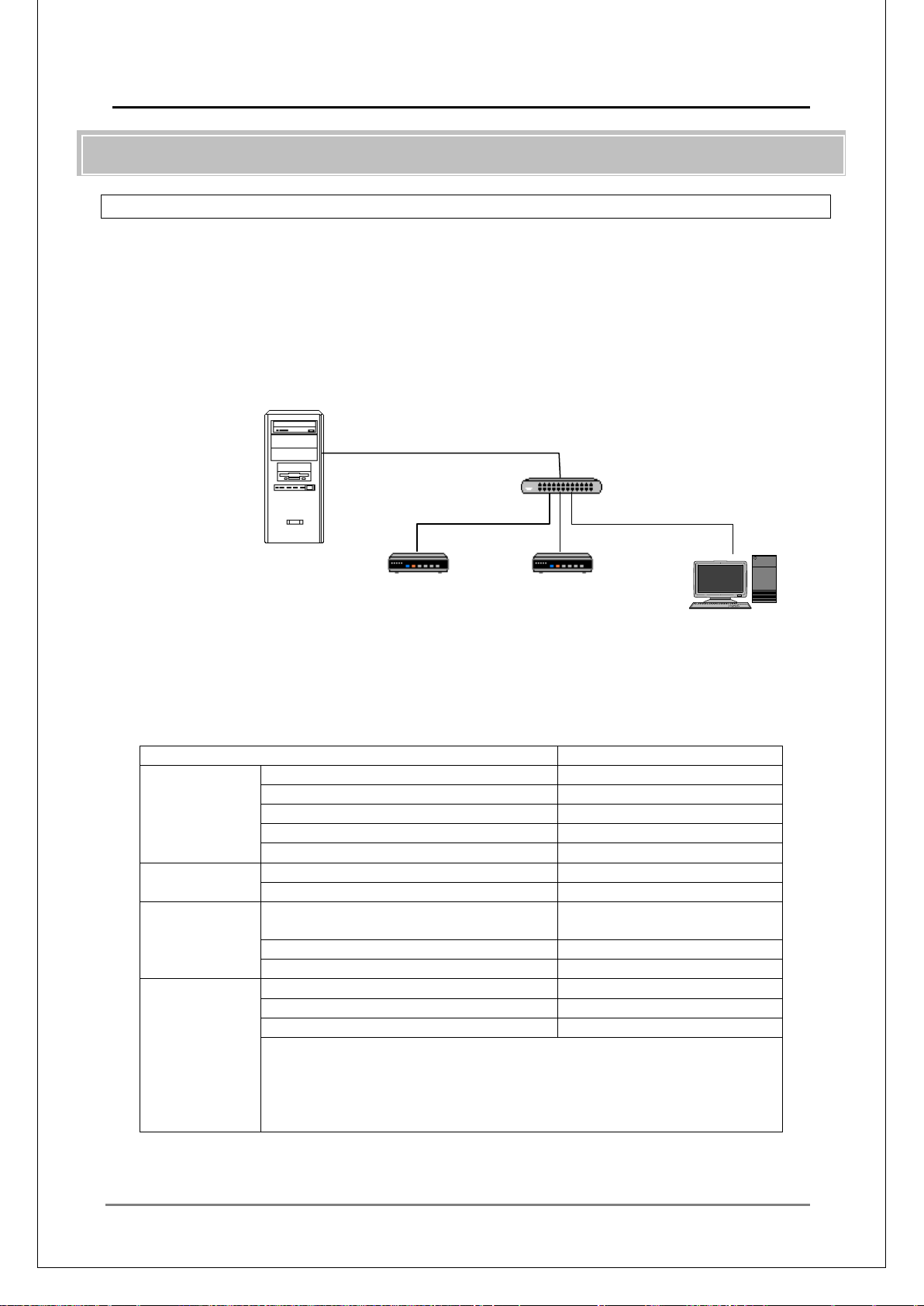
MEDIAEDGE Technical Manual Ver4.10
75
■
Computer name
mediaedge-svr
IP Address
fd00::1
Subnet Prefix Length
64
Default Gateway
None
DNS Address
::1
Primary DNS Suffix
mediaedge.local
DNS
Zone Name
mediaedge.local
Host (AAAA)
mediaedge-svr / fd00::1
Scope
fd00::0/64
(Excluding range: fd00::1)
DNS Server
fd00::1
DNS Domain Name
mediaedge.local
Router
Router Advertisement
Enabled
Managed Flag
Enabled
Other Flag
Enabled
(How to specify from netsh interface)
name.
MEDIAEDGE Server
fd00::/64
STB4
STB4
SWT4
IV-7. IPv6
IV-7-1. Configuration wi th out an IPv6 router
System configuration example with mixed configuration with MEDIAEDGE-STB4/SWT4 in
single server, single segment, without IPv6 router.
System Configuration
DB Server
Web Server
DHCPv6 Server
DNS Server
Stream Server
System Setup (Example)
MEDIAEDGE Server Setup
NIC
DHCPv6
Advertisement
netsh interface ipv6 s et interface “Local Area N et w or k”
advertise=enabled managedaddress=enabl ed ot herstateful=enabled
* Replace the “Local Area Network” section by an actual int er fa ce
Page 76
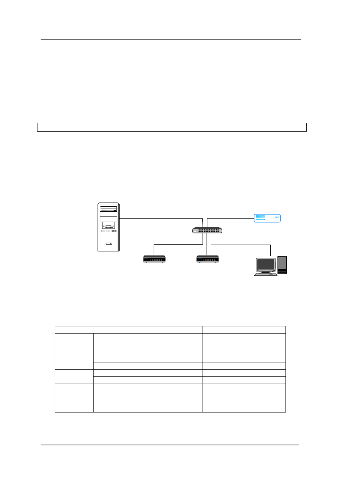
MEDIAEDGE Technical Manual Ver4.10
76
●
•
•
•
•
■
●
●
Computer name
mediaedge-svr
IP Address
fd00::1
Subnet Prefix Length
64
Default Gateway
None
DNS Address
::1
Primary DNS Suffix
mediaedge.local
DNS
Zone Name
mediaedge.local
Host (AAAA)
mediaedge-svr / fd00::1
Scope
fd00::0/64
(Excluding range: fd00::1)
DNS Server
fd00::1
DNS Domain Name
mediaedge.local
MEDIAEDGE Server
fd00::/64
DB Server
STB4
SWT4
IPv6 router
Notes on the System Setup
At the factory settings, the IPv6 is disabled on MEDIAEDGE-STB4.
When the MEDIAEDGE-STB4 starts up, it issues a router solicitation. When it receives a
router advertisement, whether DHCPv6 is used is determined. Therefore, the
MEDIAEDGE Server must be ready to issue a router adv ertisement w ithin sever al tens of
seconds after the , MEDIAEDGE-STB4 starts up.
In DHCPv6 configuration, Choose [Disable DHCPv6 stateles s m ode] .
On the DNS tab of the DHCP scope properties, check [Always update AAAA and PTR
record of DNS dynamically].
IV-7-2. Configuration with an IPv6 router
System Configuration example with mixed configuration with MEDIAEDGE-STB4/SWT4 in
single server, single segment, with an IPv6 router
System Configuration
Web Server
DHCPv6 Server
DNS Server
IPv6 router
Stream Server
System Setup (Example)
MEDIAEDGE Server Setup
NIC
STB4
DHCPv6
Page 77
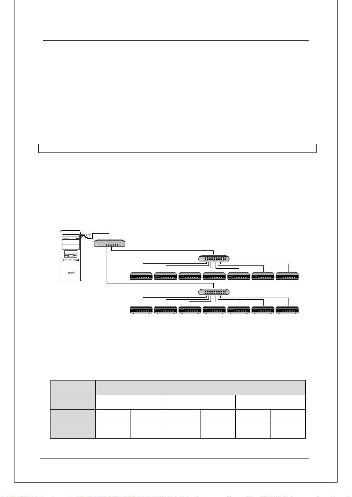
MEDIAEDGE Technical Manual Ver4.10
77
●
•
•
•
•
•
■
●
MLD function not
used
Multicast
address
Video
(Client)
Amount of
reception
MEDIAEDGE Server
DB Server
L3 switching HUB
L2 switching HUB
L2 switching HUB
fd00::1/64
Notes on the system Setup
At the factory settings, the IPv6 is disabled on MEDIAEDGE-STB4.
When the MEDIAEDGE-STB4 starts up, it issues a router solicitat io n. When it receives a
router advertisement, whether DHCPv6 is used is determined. Therefore, the
MEDIAEDGE Server must be ready to issue a ro uter adv ertisement within sev eral tens of
seconds after the , MEDIAEDGE-STB4 starts up.
In DHCPv6 configuration, Choose [Disable DHCPv6 stateless mode].
On the DNS tab of the DHCP scope properties, check [Always update AAAA and PTR
record of DNS dynamically].
Enable Managed flag and O flag in settings options on the router advertisement on the
IPv6 router. See the product manual for how to modify the router settings.
IV-7-3. Controlling multicast stream by MLDv2
In IPv6, MLD (Multicast Listener Discovery ) pr ovides the similar functions as IGMP in IPv4.
By constructing a network with the router or the L3 switch that has the MLDv2 snoopi ng f unction
and the L2 switch that has the MLDv2 snooping function, multicast packets can be delivered only
to the port of the clients that receives them.
System Configuratio n
(MLDv2)
(MLDv2 snooping)
Web Server
DHCP Server
DNS Server
Stream Server
(MLDv2 snooping)
In this construction, the MLDv2 router has two roles: a role as a MLDv2 querier MLDv2 and a role
to block unknown multicast packets.
MLD snooping controls on each multicast address, setting unique multicast address to each
channel will prod uc e good result.
The channels whose multicast addresses are same and that have different ports are regarded as
they are in a multicast group.
・When 8 channels are created, and when contents of 10Mbps is sent.
MLD function used
--- Same Unique
Playing Stop Playing Stop Playing Stop
80Mbps 80Mbps 80Mbps 0Mbps 10Mbps 0Mbps
Page 78

MEDIAEDGE Technical Manual Ver4.10
78
●
Computer name
mediaedge-svr
IP Address
fd00::1
Subnet Prefix Length
64
Default Gateway
None
DNS Address
::1
Primary DNS Suffix
mediaedge.local
DNS
Zone Name
mediaedge.local
Host (AAAA)
mediaedge-svr / fd00::1
Scope
fd00::0/64
DNS Server
fd00::1
DNS Domain Name
mediaedge.local
Router
Router Advertisement
Enabled
Managed Flag
Enabled
Other Flag
Enabled
(How to specify from netsh interface)
section by an actual interface
name.
●
•
•
•
•
•
•
To make good use of the MLDv2 function, specify unique address to the multicast address of the
channels.
Using Source-Specific Multicast (ff3x::/96) allows you to filter the clients according to the source
address by a multicast address, producing the similar result as above. In this case, multiple IPv6
addresses must be specified on the MEDIAEDGE Server, and the network interfaces that send
stream must be changed accor ding to the channels.
System Setup (Example)
MEDIAEDGE Server Setup
NIC
DHCPv6
Advertisement
netsh interface ipv6 s et interface “Local Area N et w or k”
advertise=enabled managedaddress=enabl ed ot herstateful=enabled
* Replace the “Local Area Network”
Notes on the System Setup
Enable MLDv2 on the L3 switch or the router.
Enable MLDv2 snooping function on the L2 switch.
If the DHCPv6 server and the DHCPv6 clients belong to different segment, DHCPv6
relay function is required on t he L3 switch or router
In DHCPv6 configuration, Choose [Disable DHCPv6 stateless mode].
On the DNS tab of the DHCP scope properties, check [Always update AAAA and PTR
record of DNS dynamically].
To issue a router adver tisement from the IPv6 rout er, above router advert isement settings
is not required, equivalent settings must be done on the IPv6 router. See the product
manual for how to modify sett ings on the router.
(Excluding range: fd00::1)
Page 79

MEDIAEDGE Technical Manual Ver4.10
79
V.
Settings and Operation Controls
Page 80
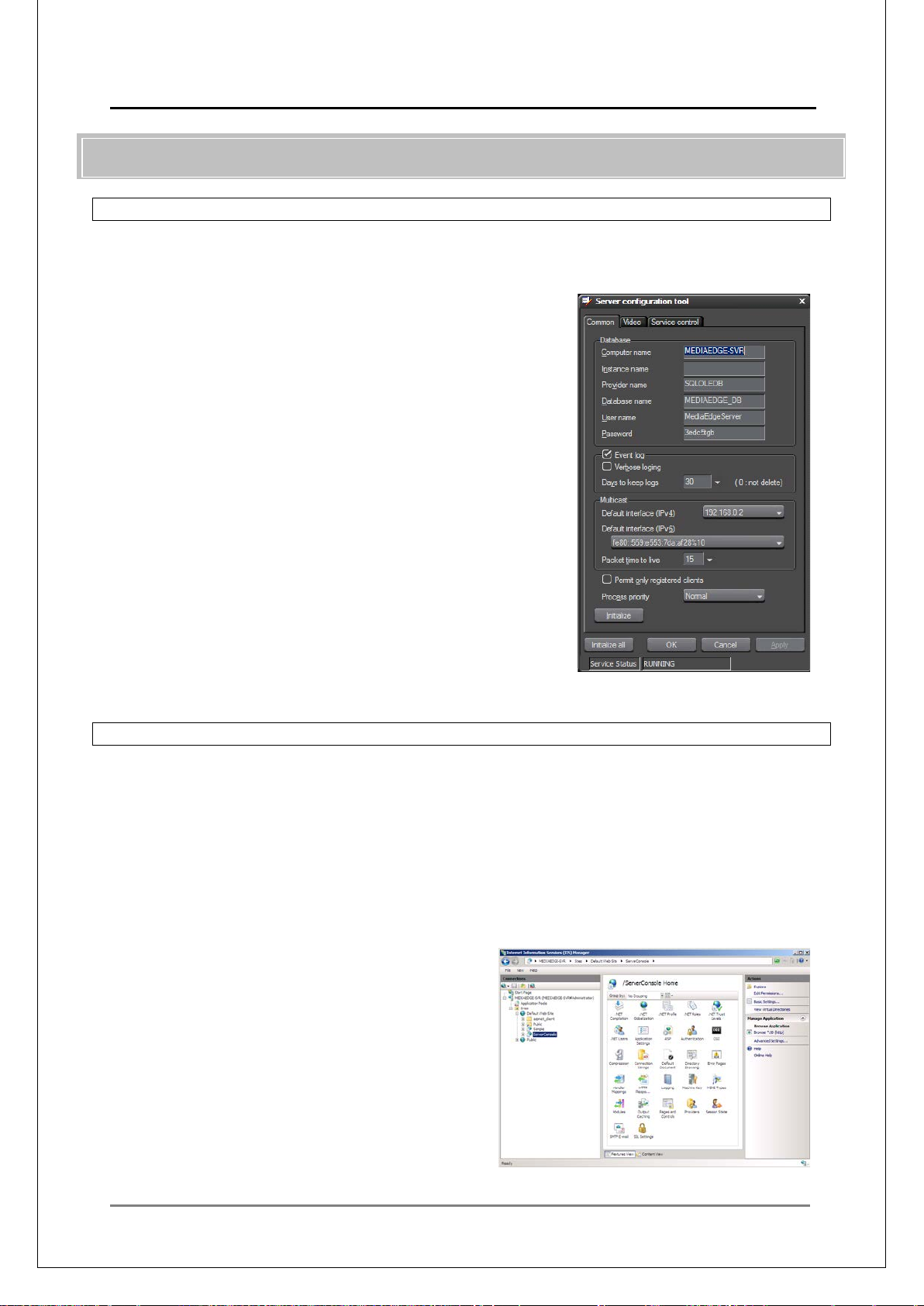
MEDIAEDGE Technical Manual Ver4.10
80
■
■
V-1. Server
V-1-1. Setting the exent log
The settings on the MEDIAEDGE-SVS4 event log can be specified by the Server Configuration
Tool.
Check [Event log] on the [Common] tab, to record log in
the T_EventLog table on the database. The log can be
viewed on the Event Log page of the Server console.
Check [verbose loging] to record more events.
For details, See the T_EventLog section on the
“MEDIAEDGE Technical Manual - Technical References
-".
V-1-2. Web server security
■ IIS security settings
In the default IIS settings after t he MEDIAEDGE installation, t he “Server console” uses the
integrated Windows authentication , while “Sample” allows the anonymous user access.
This section describes how to limit the users who can access the "ServerConsole".
[1] Choose [Start] > [Administrative Tools] and run the "Internet Information Service (IIS)
Manager".
[2] Sekect [ServerConsole] in [Default Web
site].
Page 81
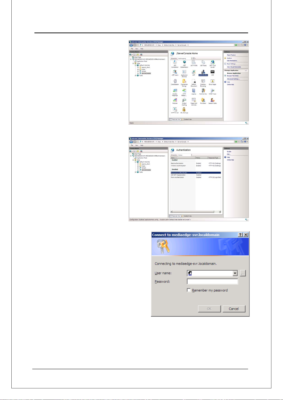
81
[3] Change the screen to [Feat ur e
View] and double-click
[Authentication].
[4] Change [Anonymous
Authentication] to [Disab le].
Setting is completed.
When you open a browser and access
http://mediaedge-svr/ServerConso le/ , t he
password input dialo g appears.
Enter the user name and the pas s w or d.
MEDIAEDGE Technical Manual Ver4.10
Page 82
MEDIAEDGE Technical Manual Ver4.10
82
■
V-1-3. Synchronizi ng t he Clock
For successful scheduled playback or recording, the system c lock must be accurate. If the system
is connected to the Int ernet, it is wise to use the NT P. If the syst em is not c onne cted to the Internet,
you may want to use an atomic clock or an FM clock.
To adjust multiple clocks on the MEDIAEDGE system, it is recommended that you use an NTP
server . You can prepare a time-server device that supports NTP, or you can conf igure the serv er to
be an NTP server t o w hich cli ents refer.
[How to set up NTP Server on Windows server]
Changing registry
Set
HKEY_LOCAL_MACHINE\SYSTEM\CurrentControlSet\Services\W32Time\Config\AnnounceFlag
s to "5."
Set
HKEY_LOCAL_MACHINE\SYSTEM\CurrentControlSet\Services\W32Time\TimeProviders\NtpSer
ver\Enabled to "1."
Restart the service "Windows Time."
Time adjust pr ogram
A progr am that ad just the ser ver clock utiliz ing an at om ic cloc k or a FM c lock i s av ailable.
For details, contact MEDIAEDGE.
Page 83

MEDIAEDGE Technical Manual Ver4.10
83
■
●
ID assignment
DIP switches
Note
Setting ID by remote controller
operations
All switches are OFF
Factory default
ID is fixed to 0
Only SW1 is set to ON
ID is fixed to 1
Only SW2 is set to ON
ID is fixed to 2
Only SW3 is set to ON
ID is fixed to 3
Only SW4 is set to ON
●
V-2. Client
V-2-1. Changing the remote control ID
You can allocate the number 0 to 3 to your MEDIAEDGE-STB4/STB4H/HDMA-4100 and the
remote controller. Default ID is 0. The setting must be performed on both the remote controllers
and the units.
Assigning ID to Remote Cont r ol
You can allocate the ID number 0 to 3 t o each r emote controller.
Modify the setting with any of the numeric number, [0], [1], [2] or [3] and the down key. No
signal, such as sound or message, appears, when the ID number is changed.
Example) Set ID to 3
1. Press "3" and downward arrow key at the s ame time for more than one second.
2. Now, MEDIAEDGE-STB4 with ID# 3 can be controlled by the remote control.
Setting by DIP switch
You can assign the ID nu mber by t he DIP sw itch. The DIP switches to assign ID num ber c an
be found under the battery lid of the remote controller .
Assigning ID to MEDIAEDGE-STB4/STB4H/HDMA-4100
You can connect a MEDIAEDGE-STB4/STB4H/HDMA-4100 to a server that has a DHCP to
acquire IP addre ss auto matica lly, or assign IP address to a MEDIAEDGE-STB4/STB4H/HDMA4100 manually.
1. Startup Internet Explorer and open the MEDIAEDGE-STB4/STB4H/HDMA-4100 Web
Console.
Example) When the IP address to the MEDIAEDGE-STB4/STB4H/HDMA-4100 is
192.168.0.16:
<URL http://192.168.0.16>
2. When MEDIAEDGE-STB4/STB4H/HDMA-4100 settings page appears, click [Settings] –
[Local settings] – [System].
3. Select ID number from "Remote control ID".
4. When finished, click "Apply " at the top right corner of t he page.
5. Enter the user name and the password, and then click [Save].
6. Once the setting is done, you can operate the MEDIAEDGE-STB4/STB4H/HDMA-4100
with a remote controller of t he spec i f ied ID.
Page 84

MEDIAEDGE Technical Manual Ver4.10
84
■
V-2-2. Notes on Setting Up Usi ng I nternet Explorer
Notes on Internet Explorer Temporar y Files
MEDIAEDGE-STB4/STB4H/HDMA-4100 can be set up using Web browsers i.e. Internet
Explorer (it’s called the Web Console). When using Internet Explorer, it may look as if
changes have not been reflected w hen the settings page is re-opened after initializing the
settings or after upgrading the firmware. This is due to cache remaining in the Internet
Explorer. Changes have been implemented in the MEDIAEDGE-STB4/STB4H/HDMA4100, but by further changing the settings without reloading the Internet Explorer, old
settings left on the cache will once again be written over on MEDIAEDGE-STB4/STB4H/
HDMA-4100 and the settings can never be initialized. Remember to reload the Internet
Explorer after initialization or updating firmware by clicking the browser refresh button
while pressing the "Ctrl" key before making further changes.
Notes on Windows Server 2008/Windows Server 2008 R2/Windows
Server 2003
In the Windows Server 2008/Windows Server 2008 R2/Windows Server 2003
environment, the Web Console of MEDIAEDGE-STB4/STB4H/HDMA-4100 may not be
properly displayed. This i s bec ause t he JavaScript is restricted. (In the default sett ings of
Internet Explorer, the [Internet Zone] is restricted, and is set to [Internet].)
In such cases, in the Internet Zone setting, add the URL of the Web Co nsole (http://"IP
address to the device"/) to [Tr ust ed sit es] or [Local intranet].
Notes on Windows Vista/Windows 7
When MEDIAEDGE-SWT4 (ActiveX Control) is used on Internet Explorer 7 or later, note
that ActiveX controls may not be loaded properly, or their functions may be limited. In
those cases, access the int er net zone settings and add “MEDIAEDGE-SWT4” to “trusted
site” or enable “security mode”.
Page 85
MEDIAEDGE Technical Manual Ver4.10
85
■
●
V-2-3. Updating firmware
MEDIAEDGE-STB4/STB4H/HDMA-4100 firmware will be updated, using the Web Console.
Open the MEDIAEDGE-STB4/STB4H/HDMA-4100 setup page from a Web browser and open
[System] - [Firmware Update], and specify the storage path where firmware archive files are
stored.
If the firmware update file exists on the computer where you open the Web browser, press the
[Browse] button on the [Firmware update] page to open the dialog, and choose the update file, so
as to specify the file as follow s .
C:\MediaEdge\public\
STB4\stb4.1.5.3.system
Firmware update file
There are following types of t he f irmware update files.
Example) Firmware versi on: 1.5.3
・stb4.1.5.3.system: Firmware update file (that saves the settings)
・stb4_full.1.5.3.system: Firmware update file (that updates the settings completely)
・stb4_mnt.1.5.3.tgz: Firmware binary file for maintenance mode
* On the MEDIAEDGE-SVS4 DVD-ROM, files are stored in the [Rom] folder.
- \SVS\Firmware\STB4\Rom
- \SVS\Firmware\STB4H\Rom
- \SVS\Firmware\HDMA-4100\Rom
[Disable version check] o ption
When this option is checked, the firmware is updated regardless of the current version.
Therefore, version down o f the MEDIAEDGE-STB4/STB4H/HDMA-4100 will be available.
When this option is unchecked, the firmware can only be updated from the current version to a
higher version.
Downgrading the firmware
If you want to downgrade the firmware, make sure to use the firmware
“stb4_full.xxx.system”.
Using “stb4.xxx.syst em m ay cause troubles on the operations.
Page 86
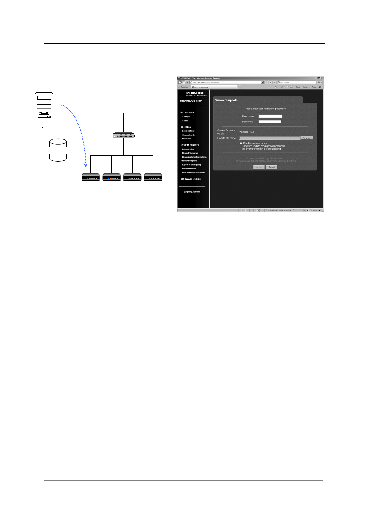
MEDIAEDGE Technical Manual Ver4.10
86
It takes a certain ti m e t o update.
Do not play contents or perform remote controller operations while update is in progress. Do not
turn off the MEDIAEDGE-STB4/STB4H/HDMA-4100.
stb4.xxx.system
Firmware
Archive file
STB
STB
STB
STB
Page 87
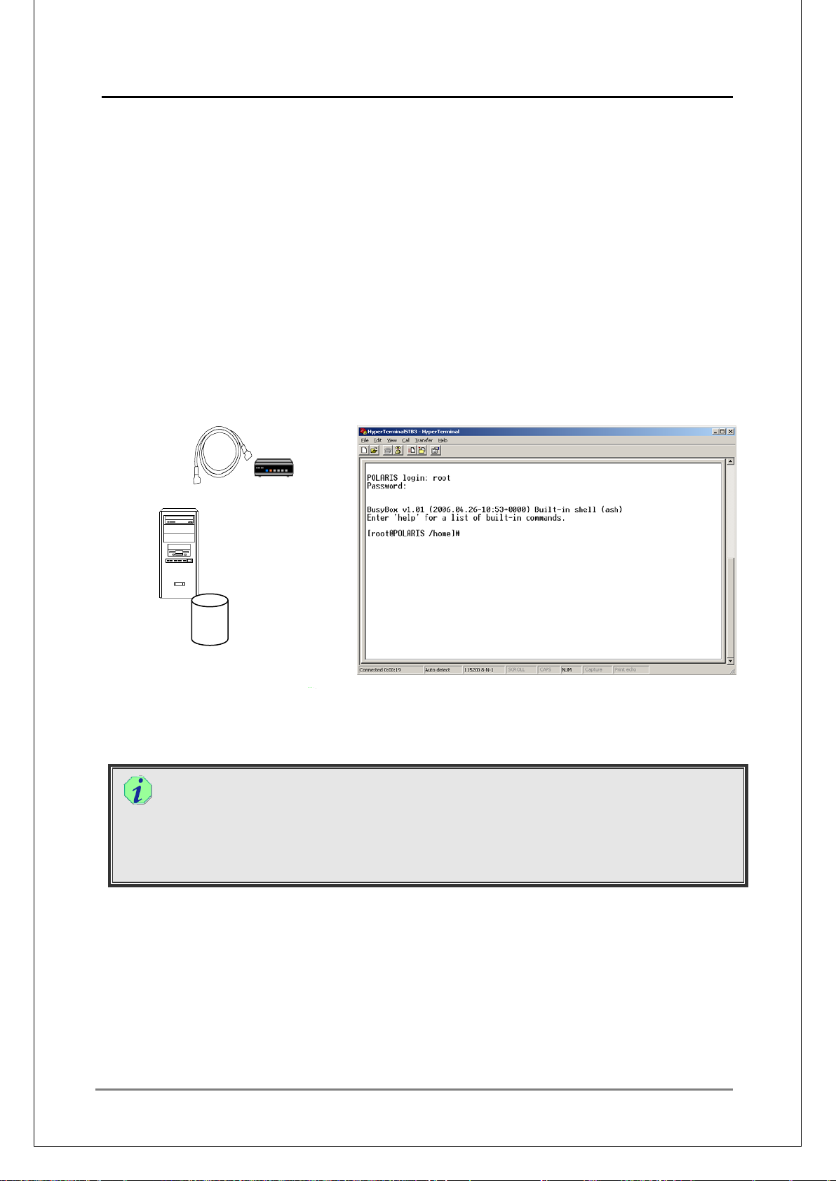
MEDIAEDGE Technical Manual Ver4.10
87
●
●
stb4_mnt.xxx.tgz
Updating MEDIAEDGE-STB4/STB4H/HDMA-4100 in maintenance mode
MEDIAEDGE-STB4/STB4H/HDMA-4100 Maintenance Mode is the recovery program that is
used when the firmware update, as described in the previous section “Updating Firmware,”
has failed and MEDIAEDGE-STB4/STB4H,HDMA-4100 no longer functions. It is also used
when you forget the user name and password that you have set in the [User name and
Password] screen.
In those cases, use the firmwar e binary file for maintenance mode to update the f irmware.
stb4_mnt.XXX.tgz (XXX is replaced with a version number.)
To use the maintenance mode, connect the computer with the MEDIAEDGE-STB4/STB4H/
HDMA-4100 with a serial cross cable, and specify the firmware binary file with a
communication soft ware such as Hyper Terminal.
For details, see the “MEDIAEDGE-STB4 Setup Guide”, “MEDIAEDGE-STB4H Setup Guide”,
“HDMA-4100 User Guide”.
STB
Firmware
binary file
Firmware binary files
The firmware binary file is stored in the [Rom] folder on the MEDIAEDGE-SVS4
Installation DVD. The extension is tgz.
- \SVS\Firmware\STB4\Rom
- \SVS\Firmware\STB4H\Rom
- \SVS\Firmware\HDMA-4100\Rom
Automatic Update via DHCP
With the [Vendor Specific Information Editor] supplied with the MEDIAEDGE-SVS4, specify
the URL for the firmware. If [DHCP] and [Automatic configuration/update via DHCP] are
enabled, the firmware will automatically be updated when the client starts up. See the
supplied manual for details.
Page 88

MEDIAEDGE Technical Manual Ver4.10
88
■
■
■
■
V-2-4. Managing clients with the Server console
Setting the client information
Registering, updating, and deleting client information is done in [Server Console] > [Client List].
Direct Control
When DHCP server is used, client registration can be executed collectively from the
leased IP address us in g " Vendor specific information editor ".
(How to manage)
From the [Command] menu of the Vendor specific inform ation editor, choose [Add STB
address to client list], to add the STB to the client list.
Changing and deleting in d ividua l clie nt infor mat ion c an be e xecut ed on " Serv e r conso le".
Control via Network
Client information can be registered, changed, and deleted on "Server console".
Surveying client status
Client status can be monitored from [ServerConsole ] > [Client Surveillance]. Connection status
and playback status will b e listed. But note that clients which have selected sched ule channels
will show up as playing back even when scheduled delivery is not being execut ed.
The information displayed on this page is the delivery status from the server to the registered
clients.
Switching/Rebooting c li ent video
Clients are control led from the "Server console".
By using [ServerConsole] – [Client Control], starting to play a specified content on a specified
client, specified group of clie nts, or all clients can be executed.
In [ServerConsole] – [Reboot], rebooting a specified client, specified group of clients, or all
clients can be execute d.
Page 89
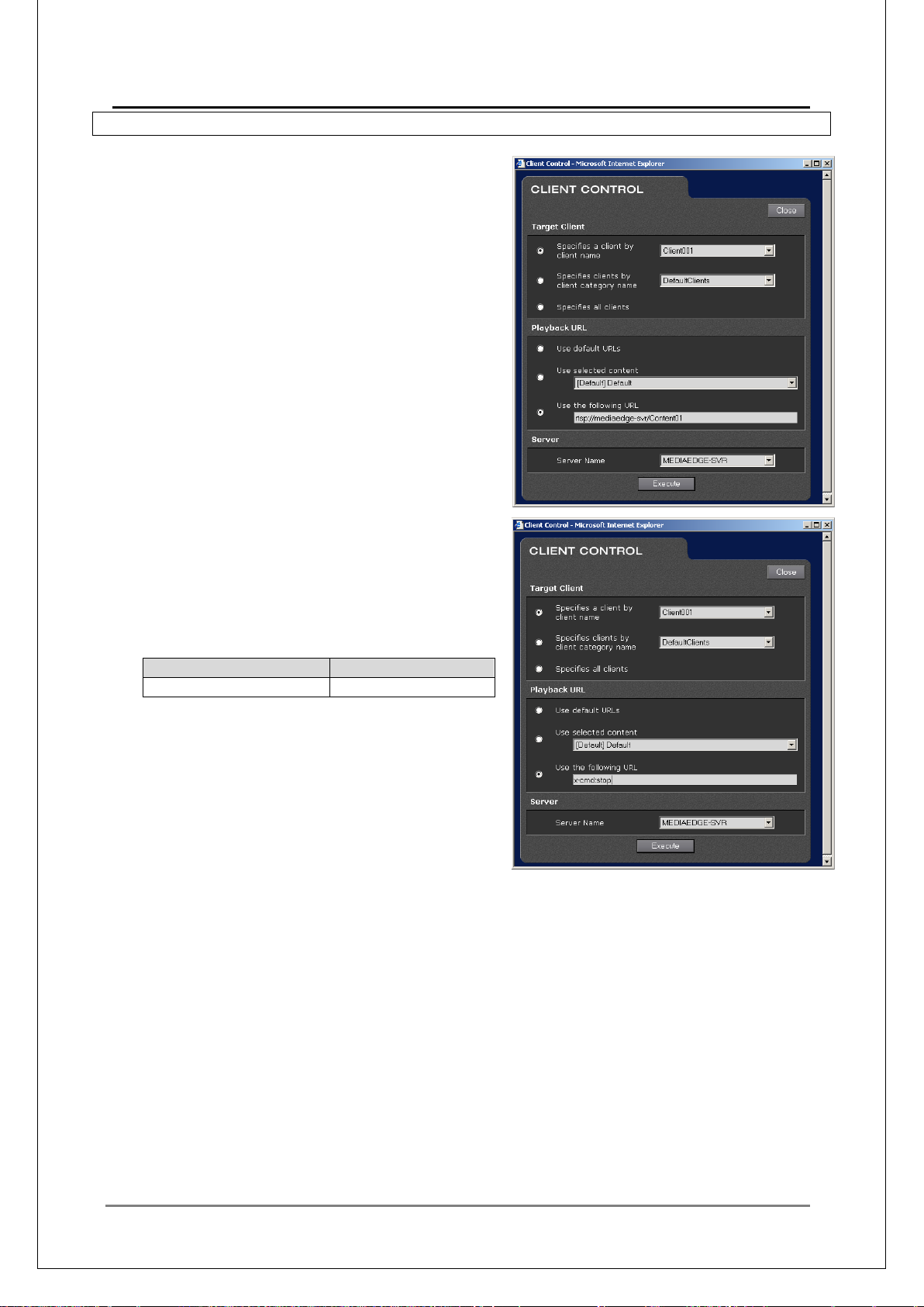
89
■
●
●
Command
Operation
x-cmd:stop
Stop
●
V-2-5. Redirect
Specify ing contents or channel s by RTSP URL
Using redirect, you can specify content by RTSP
and play it.
Description
rtsp://server name/content name
Example)
rtsp://mediaedge-svr/content01
Stop command
On MEDIAEDGE-STB4/STB4H/HDMA-4100/
MEDIAEDGE-SWT4, the following command can
be redirected as an extended co m m and.
MEDIAEDGE Technical Manual Ver4.10
For the details on other c ommands, see the
“MEDIAEDGE Technical Manual - Technical
References -".
Displaying the menu
By specifying the HTTP menu URL to the [URL] field on the Client Control dialog, the menu
can be displayed.
Note that redirecting the HTTP U RL in the Channel mode will display the menu, but the cursor
will not be displayed and the screen cannot be used as a menu. (On the HDMA-4100, as the
cursor will not appear in Schedule mode and Serial control mode, they can't be used as a
menu.)
Page 90
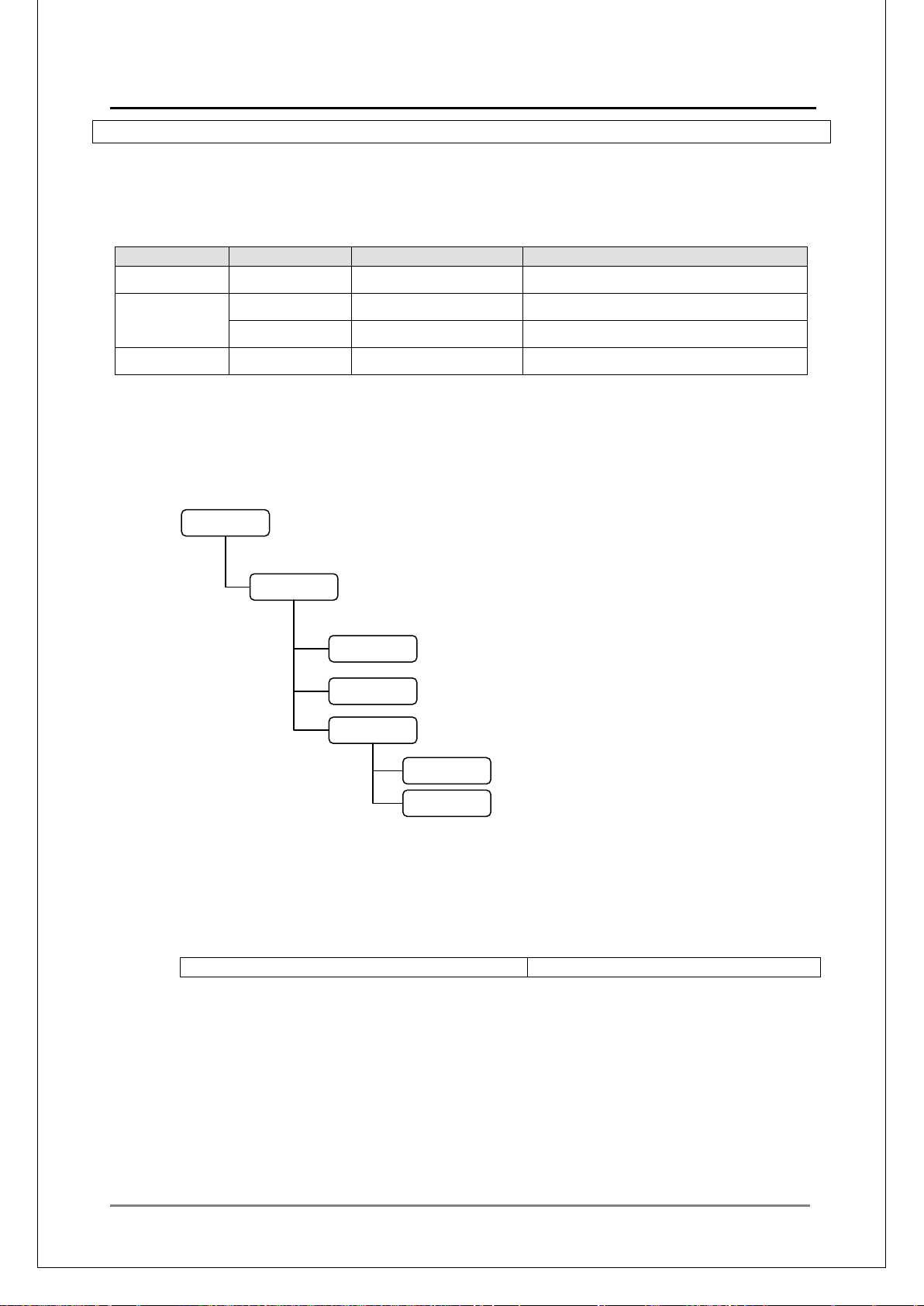
MEDIAEDGE Technical Manual Ver4.10
90
■
Name
Title
Content component s
http://server name/sample/stb4/index.asp
STB4 menu
Sample
STB4
resource
english
japanese
common.asp
index.asp
Contents.asp
menu.asp
menu_en.html
menu_ja.html
resource_set.vbs
resource_set.vbs
resource_def.asp
V-2-6. MEDIAEDGE-STB4 menu
When the MEDIAEDGE Server is installed, sample contents and the menu will also be installed.
When creating your own menu, see the sample contents and menu page. The MPEG files copied,
the names and the titles of the contents registered on the database by the installer will be as
follows.
MPEG2 Content01 The statue of liberty \Contents\Sample\Content01.m2p
MPEG2-HD
HD-Content01 Snow \Contents\Sample\HD-Content01.m2t
Resort Resort \Contents\Sample\Resort.m2p
H.264/AVC ResortAVC Resort \Contents\Sample\ResortAVC.m2ts
A sample menu page for selecting them will also be installed. There is a Static and a Dynamic
menu in the sample. The folder name on the Web server which contains these sample menus will
be specified during installation.
common.vbs
global.asa
menu.asp
dynamic
static
resource.css
Virtual directory for the Web server will be registered as "sample". Underneath that folder is the
"STB4" folder, and underneath each will be a "st atic" and a "dynamic" folders.
"static"---Menu which doe s not r efer to the database and is described only usi ng HTML.
"dynamic"---Menu that re fer s to t he datab ase and build the menu page dyna mically using ASP.
Both menus can be accessed by the following HTTP URL:
index.asp displays links to the static menu (menu_xx.html in the "static" folder) and dynamic
menu (menu.asp in the "dynamic" folder).
Stat ic menu (menu_xx.html) includes links for playing back the above listed sample contents.
Dynamic menu (menu.asp) inquires to the database for a list of categories and channels
registered in the datab as e, and creates links to them.
When one of the categories has been selected, it will call up Contents.asp. Contents.asp will
inquires to the database for a list of contents included in that category and creates links to
them. When one content is selected, it will be played back. When a channel is selected in
menu.asp, that channel wi ll be re ceived.
Page 91

91
●
Notes on St at i c m enu (that does not refer to database)
○Description of RTSP Requests
Send the following RTSP requests to the stream server for video playback req uest
rtsp://(StreamServerName)/(ContentName)
StreamServerName Stream server name
ContentName Content name registered to the database
(Note: not content title or comments)
○Description Meth od for the Menu
Describe the RTSP request on the URL of the hy per link tag.
Example:
<a href="rtsp://MEDIAEDG-SVR/Content01">Statue of Laverty </a><br>
MEDIAEDGE Technical Manual Ver4.10
Page 92

MEDIAEDGE Technical Manual Ver4.10
92
●
●
Notes on the Dynamic menu ( that refers to database)
The sample menu which refers to the database (dynamic menu) has the same mechanism
as the menu which does not refer to the database, except that it retrieves information from
the database when nec essary to make the RTSP request s.
To specify the Dynamic menu t he Home URL, specify as follows:
http://servername/sample/STB4/dynamic/index.asp
Connecting to the Database
Settings for database connection have been setup as below in \Sample\global.asa:
Sub Session_OnStart
Dim DBServerName
Dim DBName
DBServerName = "MEDIAEDG-SVR"
DBName = "MEDIAEDGE_DB"
DBUserID = "MediaEdgeUser"
DBPassword = "1qaz2wsx"
Session("ConsoleDB") = "Provider=SQLOLEDB;Data Source=" & DBServerName & _
";Initial Catalog=" & DBName & "; User ID=" & DBUserID & _
";Password=" & DBPassword & ";"
Session("Lang") = GetAcceptLanguage()
If Session("Lang") <> "en-us" And Session("Lang") <> "ja" Then
Session("Lang") = "en-us"
End If
End Sub
Values for DBServerName and DBName will differ depending on the installed
environment. The values entered for database connection ar e sav ed t o a sess ion varia ble
"ConsoleDB", therefore each ASP file will use this session variable in connecting to the
database.
Function for databas e connection is prepared in \Sample\common.asp.
Function ADOOpenConnection()
Dim objConn
Dim objErr
On Error Resume Next
Err.Clear
Set objConn = Server.CreateObject("ADODB.Connection")
If Err.Number <> 0 Then
On Error Goto 0
Set ADOOpenConnection = Nothing
Exit Function
End If
objConn.ConnectionTimeout = 20
objConn.CommandTimeout = 10
objConn.Open Session(" Cons ol eD B")
If Err.Number <> 0 Then
On Error Goto 0
Set ADOOpenConnection = Nothing
Page 93

MEDIAEDGE Technical Manual Ver4.10
93
●
Exit Function
End If
On Error Goto 0
Set ADOOpenConnection = objConn
End Function
Retrieving Content and Stream Server Names from the Database:
<!-- #include file="../../common.asp" -->
<%
Dim objConn
Dim objRecord
Dim CategoryName
On Error Resume Next
‘ Connecting database
Set objConn = ADOOpenConnection()
‘ Creating record set object
Set objRecord = Server.CreateObject("ADODB.Recordset")
%>
<html>
<head><title>MEDIAEDGE</title></head>
<body>
<% SetContentList(CategoryName) %>
<%
‘ Closing database
objConn.Close
set objRecord = nothing
set objConn = nothing
%>
</body>
</html>
<%
Sub SetContentList(s zCate goryName)
dim strServerName
if szCategoryName = "" then
SQLs = GetNoCategorySQL
else
SQLs = "SELECT * FROM T_Content WHERE ContentSystemFlag = 0 AND " & _
"ContentCategoryName = N'" & SQLEncode(szCategoryName) & "' ORDER BY
ContentName ASC"
end if
objRecord.Open SQLs, objConn, adOpenStatic,adLockReadOnly
if objConn.Errors.Count = 0 then
if objRecord.EOF then
response.write("<DIV>" & RES_NOCONTENTS & "</DIV>")
serial = serial + 1
end if
do until (objRecord.EOF)
if (serial \ 10) + 1 = PageNo then
strServerName = GetServerAlias(objRecord("ServerName"))
if InStr(strServerName, ":") then
strServerName = "[" & strServerName & "]" 'IPv6 URL Encode
Page 94

MEDIAEDGE Technical Manual Ver4.10
94
end if
response.write("<DIV>" & (serial + 1) mod 10 & ". ")
response.write("<a href='rtsp://" & strServerName & "/" &
Server.UrlEncode(objRecord("ContentName")) & "'")
response.write(" accesskey='" & (serial + 1) mod 10 & "'>")
response.write("<img src='../resource/dummy.gif' width='0' height='0' alt='" &
Encode2HTML(objRecor d( " Cont e ntTitle"),0) &"'>")
response.write( Encode2HTML( objR ecor d( "C onte ntTitle"),26) & "</a ></D IV >" &
vbCr)
end if
objRecord.MoveNext
serial = serial + 1
loop
end if
objRecord.Close
End Sub
%>
Page 95

MEDIAEDGE Technical Manual Ver4.10
95
●
●
Using form to Display User Authentication and Me nus for Individual Users
Display the user ID and password entry dialog using the <form> tag.
<form> tag allows users to input items in the STB4 menu using the remote control for
entering numbers.
【Sample】
<html>
<head>
<title>Member Authentication</title>
</head>
<body alink=#AAFFAA link=#558855>
<p>****** Enter the ID number and the pin number.******</p>
<form method="get" action="login.asp">
<p>ID number<input type="text" name="ID"></p>
<p>Pin number<input type="password" name="PW"></p>
<input type="submit" value="Submit">
<input type="reset" value="Clear">
</form>
</body>
</html>
Page 96

MEDIAEDGE Technical Manual Ver4.10
96
●
Operations witho ut Menu
Operation that does not display menus can be set specifying channel mode for the VOD
mode on clients.
[1] Open the Web Console.
[2] On MEDIAEDGE-STB4, choose [SETTINGS] - [Local settings] - [VOD mode] and
choose "Channel mode" on the [Video-on-demand] option.
* On MEDIAEDGE-STB4H/HDMA-4100:
Choose [SETTINGS] - [Local settings] - [System] and choose "Channel mode" on
the [Boot mode] option.
[3] Click [APPLY] at the top right corner of the page to app ly the settings.
[4] Open the channel mode set t ings on MEDIAEDGE-STB4/STB4H/HDMA-4100.
[5] Specify the information on [Default content] and [Ch annel setting].
・Default content
Content to be played at the startup of MEDIAEDGE-STB4/STB4H/HDMA-4100.
・Channel setting
Content to be played when a number is specified by the remote controller op er at ions.
[6] Click [APPLY] at the top right corner of the page, enter [User name] and [Password],
and then click [Save].
Page 97

MEDIAEDGE Technical Manual Ver4.10
97
■
■
V-2-7. Remote Serial
Byte-string data that is input via a MEDIAEDGE-STB4/STB4H/HDMA-4100 serial port (RS-232C)
can be transferred to anot her computer such as a server. Data transferred from another computer
can be exported from the ser ia l port.
If the IP address and port number of the target computer ar e pr edefined, data can be sent to that
target. The purpos e of thi s funct ion is to pr ovide a tr ansfer r oute betw ee n an ex ternal d ev ice and a
computer. This function does not process the data to be transferred.
Also note that the software that receives the data on a computer must be developed to
accommodate the devices us ed by those who construct the system. (Because this f unct i on
reads/writes only the netw or k por ts, SDK or sample programs are not provide d. )
Although various external devices that use RS-232C are available to conne ct, software must be
developed for the devices.
How to use the data transfer function of the serial port
[Settings]
Open the MEDIAEDGE-STB4/STB4H/HDMA-4100 Local Settings.
* On MEDIAEDGE-STB4H or HDMA-4100, open the [Serial] page and check "Remote
serial" on the [Ser ia l por t f unct ion] option in advance.
[1] At the [Remote serial] field on the [Serial], choose [Connect with the linked server] or
[Connect with the fixed host].
Link: Connects in sync with the connected stream server.
Note: Available only when it receives a stream.
Fixed: Always connects t o a fix ed host computer.
[2] If the above remote serial is set to [Connect with the fixed host], enter the host
computer name or the IP address to the [Host name or IP address] f ield.
[3] Specify the por t number to use to connect to the client at the [Host port number] field.
[4] Specify the port nu mber th at t he MEDIAEDGE-STB4/STB4H/HDMA-4100 uses at t he
[Listening port number] field.
[5] Choose a protocol to use at the [Pr ot ocol] f ie ld.
[6] Specify the communication conditions at [Baud rate], [Data bits], [Parity], [Stop bits]
fields.
[Communication method]
[1] From a computer, when data is sent to the listening port of a MEDIAEDGE-STB4/
STB4H/HDMA-4100 of the IP address, specified above, the data is output from the
serial port of the MEDIAEDGE-STB4/STB4H/HDMA-4100.
[2] The data input to the serial port of a MEDIAEDGE-STB4/STB4H/HDMA-4100 is sent
to the host port of the computer, specified above.
V-2-8. Setting Wake On LAN
MEDIAEDGE-STB4/STB4H/HDMA-4100 supports Wake On LAN.
To enable Wake On LAN, set the DIP switch 1 found on t he r ear panel of a MEDIAEDGE-STB4/
STB4H/HDMA-4100 unit, and then turn off the MEDIAEDGE-STB4/STB4H/HDMA-4100 unit.
* When the DIP switc h i s changed while the MEDIAEDGE-STB4 is turned off, the chang es do not
take effect.
Install a software that can send magic packets, and sent magic packets to a MEDIAEDGE-STB4/
STB4H/HDMA-4100.
To send magic packets, MAC address is required.
Page 98

MEDIAEDGE Technical Manual Ver4.10
98
■
At the center on the rear panel of a MEDIAEDGE-STB4/STB4H/HDMA-4100 unit, a sticker with a
MAC address is paste d.
<Note: Shutting down MEDIAEDGE-STB4/STB4H/HDMA-4100>
You can shut down the units by pressing the Power button on the remote contr oller or by SNMP.
V-2-9. Setting the output format
Hold the [MENU] button during MEDIAEDGE-STB4/STB4H/HDMA-4100 startup (from when the
unit is turned on until the system starts running) to access the Network settings screen.
On the Network settings scr een, pr ess t he DISP switch to switch the video output format.
Setting DIP switch 8 on the rear panel of the MEDIAEDGE-STB4 (DIP switch 4 on the rear panel
of the MEDIAEDGE-STB4H/HDMA-4100) to ON also opens the Network settings s cr een.
[How to open the Network Settings screen with the DIP switches]
1. Turn the MEDIAEDGE-STB4/STB4H/HDMA-4100 off if it's run ni ng.
2. Set the DIP switch 8 on the rear panel of the MEDIAEDGE-STB4 (DIP switch 4 on the rear
panel of MEDIAEDGE-STB4H/HDMA-4100) to ON.
3. Run the MEDIAEDGE-STB4/STB4H/HDMA-4100, and wait until the Power LED changes
from blinking to lit.
4. By pressing the [DISP] button on the r em ot e c ont r oller, the output format wil l change.
When the video format is set t o a pr oper one, "Network settings" screen appears.
5. Pressing [OK] will reboot the MEDIAEDGE-STB4/STB4H/HDMA-4100.
6. While the MEDIAEDGE-STB4/STB4H/HDMA-4100 is starting up, set the DIP switch on the
rear panel of the MEDIAEDGE-STB4/STB4H/HDMA-4100 back to OFF.
* If you fail to set the DIP switch back to OFF, press the [POWER] button on the remote controller
to shut down the MEDIAEDGE-STB4, and then set it to OFF.
[Switching order of the vid eo format]
1. NTSC(J)
2. 1080/59.94i(Component) * MEDIAEDGE-STB4 only
3. 720/59.94p(Component) * MEDIAEDGE-STB4 only
4. NTSC(US)
5. PAL
6. 1080/50i(Component) * MEDIAEDGE-STB4 only
7. 720/50p(Component) * MEDIAEDGE-STB4 only
8. 1080/59.94i(HDMI)
9. 720/59.94p(HDMI)
10. 720x480/59.94p(HDMI)
11. 1080/59.94p(HDMI)
12. 1080/50i(HDMI)
13. 720/50p(HDMI)
14. 720x576/50p(HDMI)
15. 1080/50p(HDMI)
16. 640x480/60p (HDMI)
Then it returns to 1.NTSC(J) and repeats the cycle.
* The available video formats and their switching order differ according to the client devices.
Page 99
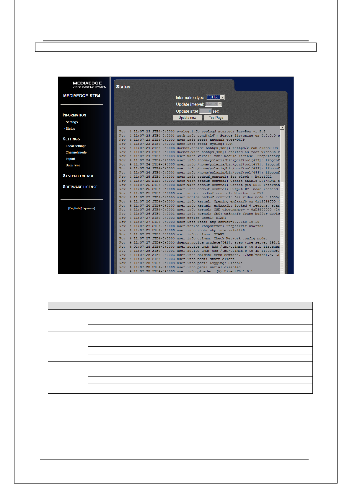
99
■
Device
Display type
Description
STB4
Status
Lists the status of the unit chronologically.
Full log
Lists the full log chronologically .
Play log
Displays the operational status of play/stop chronologically.
STB4H
Status
Lists the status of the unit chronologically.
Full log
Lists the full log chronologically .
Play log
Lists the operati onal status of play/stop chronologic ally.
Transfer log
Lists the operational status of file transfer chronologically.
HDMA-4100
Status
Lists the status of the unit chronologically.
Full log
Lists the full log chronologically .
Play log
Lists the operati onal status of play/stop chronologic ally.
V-2-10. Reviewing the log
You can check the operation status w ith the log.
Open the [Status] page with a Web br ow ser.
MEDIAEDGE Technical Manual Ver4.10
Log type
The log contents to display can be selected by [Display type].
Transfer log Lists the operational status of fil e t r ansfer chronologically.
With the [Update intervals] option, automatic update with the specified intervals or manual update
can be applied.
Page 100
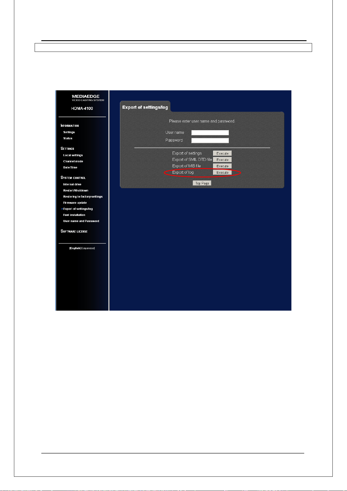
MEDIAEDGE Technical Manual Ver4.10
100
■
V-2-11. Downloading the log file
Y ou can down load the full log as a file from the [SYSTEM CO NTROL – Export of settings/log] page
of the Web Console.
Open the Setup screen with a Web browser and choose [SYSTEM CONTROL – Export of
settings/log – Export of lo g] .
 Loading...