

Media5 Mediatrix 4401, Mediatrix4402, Mediatrix 4401plus, Mediatrix 4402plus, Mediatrix 4404 Installation Manual
Page 1

Discover the Power of 5
Hardware Installation Guide
Mediatrix® 4400 Series
Digital Gateways
Mediatrix 4401 / 4402 / 4404 and plus models (BRI)
Product Version 2.0 Document Revision 16
March 1, 2012
Pb
RoHS
COMPLIANT
2002/95/EC
Page 2

Media5 Corporation Hardware Installation Guide
Media5 Corporation
4229 Garlock Street
Sherbrooke, Québec, Canada J1L 2C8
Mediatrix® 4400 Series Hardware Installation Guide
© 2012, Media5 Corporation
All rights reserved. No part of this publication may be reproduced or used in any form or by any means
– graphic, electronic, or mechanical, including photocopying, recording, taping, or information storage
and retrieval systems – without the express written permission of the publisher.
Media5 Corporation reserves the right to revise this publication and make changes at any time and
without the obligation to notify any person and/or entity of such revisions and/or changes.
Trademarks
Microsoft and Windows are registered trademarks of Microsoft Corporation.
Adobe and Acrobat are registered trademarks of Adobe Systems Incorporated.
All other trademarks and registered trademarks are the property of their respective owners.
Third-Party Software Copyright Information
®
The Mediatrix
4400 Series firmware aggregates some third-party software modules (open source
and commercial) that are distributed to you in accordance with their respective licenses. Refer to the
Third Party Software Copyright Information addendum available on the Mediatrix Download Portal,
which lists the third-party software modules along with any copyright and license information.
Page 3

Hardware Installation Guide
Contents
Preface
About this Manual.............................................................................................................vii
Document Objectives.................................................................................................................................. vii
Intended Audience..................................................................................................................................... viii
Related Documentation............................................................................................................................. viii
Document Structure................................................................................................................................... viii
Document Conventions ...............................................................................................................................ix
Warning Definition................................................... ... .................................................................................................ix
Other Conventions ......................................................................................................................................................ix
SCN vs PSTN..............................................................................................................................................................ix
Standards Supported ............................................................................................................ ......................................ix
Obtaining Documentation.............................................................................................................................x
Media5 Web Site......................................................................................................................................................... x
Media5 Download Portal............................................................................................................................................. x
Documentation Feedback ........................................................................................................................................... x
End User Technical Support.........................................................................................................................x
Chapter 1
Overview ..............................................................................................................................1
Overview.......................................................................................................................................................1
Key Features...............................................................................................................................................................1
Mediatrix 4400 Connectors and Indicators ............... ....................................... ... ... ... ....................................2
Product Serial Number Location .................................................................................................................................2
Front Indicators and Connectors.................................................................................................................................2
Rear Connectors.........................................................................................................................................................3
Port Numbering Convention ..................................... ... ....................................... ... ... .... ................................4
Bypass Feature (Mediatrix 4402plus / 4404plusModels)..............................................................................4
Chapter 2
Installation ...........................................................................................................................5
Planning the Installation................................................................................................................................5
Installation Checklist....................................................................................................................................................5
Site Log.......................................................................................................................................................................6
Network Information....................................................................................................................................................6
Safety Recommendations.............................................................................................................................6
Maintaining Safety with Electricity...............................................................................................................................6
General Safety Practices.............................................................................................................................................7
Preventing Electrostatic Discharge Damage...............................................................................................................7
Required Mounting Tools and Equipment ....................................................................................................7
Unpacking and Inspection ............................................................................................................................7
Location and Mounting Requirements .........................................................................................................8
Location.......................................................................................................................................................................8
Wall-Mounting .............................................................................................................................................................9
Free Standing Unit .......................................................... ... .................................... ... ... ...............................................9
Condensation ..............................................................................................................................................................9
Cleaning......................................................................................................................................................................9
Mediatrix 4400 – Digital Gateway
iii
Page 4

Contents
Hardware Installation..................................................................................................................................10
Connecting Cables....................................................................................................................................................10
Chapter 3
Powering on the Mediatrix 4400.......................................................................................13
IP Address Discovery or Configuration.......................................................................................................13
Dynamic IPv4 Address Discovery............................................................................................................................. 13
Default Static IPv4 Address Configuration................................................................................................................14
IPv6 Link Local Address Configuration .....................................................................................................................15
Verifying the Installation............................................................................................................................................15
Indicators (LEDs)........................................................................................................................................16
LED Patterns – Specific Conditions ..........................................................................................................................16
LED Patterns – Default Behaviour ......................................................... .. ... .............................................................. 17
RESET/DEFAULT Button...........................................................................................................................18
At Run-Time..............................................................................................................................................................18
At Start-Time.............................................................................................................................................................18
Partial Reset..............................................................................................................................................................19
Factory Reset............................................................................................................................................................20
Management Choices.................................................................................................................................20
Appendix A
Standards Compliance and Safety Information .............................................................21
Standards Supported..................................................................................................................................21
Disclaimers .................................................................................................................................................22
CE Marking................................................................................................................................................................22
RoHS China ..............................................................................................................................................................22
Translated Warning Definition ....................................................................................................................23
Safety Warnings .........................................................................................................................................24
Circuit Breaker (15A) Warning ..................................................................................................................................24
TN Power Warning.................................................................................................................................................... 24
Product Disposal Warning.........................................................................................................................................24
No. 26 AWG Warning................................................................................................................................................24
LAN Connector Warning ...........................................................................................................................................24
ISDN BRI Connector Warning...................................................................................................................................24
Socket Outlet Warning ..............................................................................................................................................25
Safety Recommendations...........................................................................................................................25
Appendix B
Cabling Considerations....................................................................................................27
RJ-45 Cable................................................................................................................................................27
Straight Through Cable.............................................................................................................................................28
Crossover Cable........................................................................................................................................................29
Appendix C
Standard Hardware Information.......................................................................................31
Industry Standard Protocols ..................................... ... ... .... ... ... ... ....................................... ... .....................31
Hardware Features.....................................................................................................................................32
Interfaces...................................................................................................................................................................32
Power........................................................................................................................................................................32
iv
Mediatrix 4400 – Digital Gateway
Page 5

Hardware Installation Guide
Product Architecture Details.......................................................................................................................32
Real Time Fax Router Technical Specifications.........................................................................................32
Audio Specifications ...................................................................................................................................33
DTMF Tone Detection ........................................................................ ... ... ... ...............................................33
DTMF Tone Generation.................. ... .... ... ... ....................................... ... ... ... ...............................................33
Power Consumption ...................................................................................................................................34
MTBF Value.................... ... ... .... ... ....................................... ... ... ... ...............................................................34
Operating Environment................... ... .... ...................................... .... ... ... ... ..................................................34
Dimensions and Weight..............................................................................................................................34
Warranty.....................................................................................................................................................35
Appendix D
Glossary.............................................................................................................................37
Appendix E
List of Acronyms...............................................................................................................41
Mediatrix 4400 – Digital Gateway
v
Page 6

Contents
vi
Mediatrix 4400 – Digital Gateway
Page 7

P REFACE
P
About this Manual
Thank you for purchasing the Mediatrix 4400 Series from Media5 Corporation.
The Mediatrix 4400 Series ISDN BRI VoIP Digital Gateways allow enterprises to lower communications costs
over any IP link. The Mediatrix 4400 units constitute an ideal solution for enterprise voice applications or for
connecting to a service provider’s broadband access.
Table 1: Mediatrix 4400 Series Models
Model Interfaces
Mediatrix 4401 1 BRI port up to 2
Mediatrix 4401plus 1 BRI port up to 2
Mediatrix 4402 2 BRI ports up to 4
Mediatrix 4402plus 2 BRI ports up to 4
The Mediatrix 4402plus and Mediatrix 4404plus models may use either BRI port #1 or BRI port #2 as a bypass
port for optimized call-routing and risk-free operation. See “
4404plusModels)” on page 4 for more details.
The Mediatrix 4400 Series ISDN BRI VoIP Digital Gateways offer two Ethernet connectors switches enabling
to establish two connections between conventional analog telephones or Group 3 fax machines and either a
WAN, a LAN or a personal computer.
VoIP Call
Capacity
Bypass Feature (Mediatrix 4402plus /
BRI Power
Feeding
Power over
Ethernet
Bypass
Document Objectives
The Mediatrix 4400 Hardware Installation Guide provides technical information on how to physically install the
Mediatrix 4400. It also describes the cabling required for the Mediatrix 4400 device.
The information included in this guide consists of:
Hardware descriptions of the Mediatrix 4400 device
Hardware installation instructions
Installation scenarios examples
LED indications
Cabling and pin-out data
Note: There are many flavours of the Mediatrix 4400 device. Because of this, some of the information
provided may not apply to your particular Mediatrix 4400 device model.
Please refer to the Dgw v2.0 Software Configuration Guide for software configuration information.
Use the Mediatrix 4400 Hardware Installation Guide in conjunction with the appropriate publications listed in
Related Documentation” on page viii.
“
Mediatrix 4400 – Digital Gateway
vii
Page 8

Preface - About this Manual Intended Audience
Intended Audience
This guide is intended for the following audiences:
Technical staff who are familiar with electronic circuitry, networking theory and have experience
as an electronic technician.
System administrators with a basic networking background and experience, but who might not
be familiar with the Mediatrix 4400 device.
System administrators who are responsible for installing and configuring networking equipment
and who are familiar with the Mediatrix 4400 device.
Related Documentation
In addition to this manual, the Mediatrix 4400 document set includes the following:
Dgw v2.0 Software Configuration Guide
Describes how to configure and operate the Mediatrix 4400.
Mediatrix 4400 Installation Guide
This booklet allows you to quickly setup and work with the Mediatrix 4400. The booklet for your
specific platform is available at: http://www.media5corp.com/quickstart
Configuration Reference Guide
Lists all the parameters, tables, and commands available in the Mediatrix 4400.
Notification Reference Guide
Lists and describes all syslog messages and notification messages that the Mediatrix 4400 may
send.
Third Party Software Copyright Information
This document lists the third-party software modules used in the Mediatrix 4400 along with any
copyright and license information. This document is available at: http://www.media5corp.com/
repository/common%20manuals/Third-Party_Software_Copyright_Information_Mediatrix.pdf.
Be sure to read any readme files, technical bulletins, or additional release notes for important information.
Document Structure
The Mediatrix 4400 Hardware Installation Guide contains the following information.
“Chapter 1 “Chapter 2 -
“Chapter 3 page 13
“Appendix A Information” on page 21
“Appendix B page 27
viii
Overview” on page 1 Provides a brief description of the Mediatrix 4400.
Installation” on page 5 Contains instructions for installing the Mediatrix 4400
Powering on the Mediatrix 4400” on
Standards Compliance and Safety
Cabling Considerations” on
Table 2: Mediatrix 4400 Hardware Installation Guide Chapter/Appendices
Title Summary
and connecting the cables.
Leads you through the basic steps to start the
Mediatrix 4400.
Lists the various standards compliance of the
Mediatrix 4400.
Describes the pin-to-pin connections for cables used
with the Mediatrix 4400.
Mediatrix 4400 – Digital Gateway
Page 9
Document Conventions Hardware Installation Guide
Table 2: Mediatrix 4400 Hardware Installation Guide Chapter/Appendices (Continued)
Title Summary
“Appendix C on page 31
Standard Hardware Information”
Document Conventions
The following information provides an explanation of the symbols that appear on the Mediatrix 4400 and in the
documentation for the product.
Warning Definition
Warning: Means danger. You are in a situation that could cause bodily injury. Before you work on any
equipment, you must be aware of the hazards involved with electrical circuitry and be familiar with standard
practices for preventing accidents.
Where to find Translated Warning Definition
For safety and warning information, see “Appendix A - Standards Compliance and Safety Information” on
page 21.
This Appendix describes the international agency compliance and safety information for the Mediatrix 4400. It
also includes a translation of the safety warning listed in the previous section.
Other Conventions
Lists the technical hardware information of the
Mediatrix 4400.
The following are other conventions you will encounter in this manual.
Caution: Indicates a potentially hazardous situation which, if not avoided, may result in minor or moderate
injury and/or damage to the equipment or property.
Note: Indicates important information about the current topic.
Standards Supported Indicates which RFC, Draft or other standard document is supported for a
SCN vs PSTN
In Media5’ and other vendor’s documentation, the terms SCN and PSTN are used. A SCN (Switched Circuit
Network) is a general term to designate a communication network in which any user may be connected to any
other user through the use of message, circuit, or packet switching and control devices. The Public Switched
Telephone Network (PSTN) or a Private Branch eXchange (PBX) are examples of SCNs.
Standards Supported
When available, this document lists the standards onto which features are based. These standards may be
RFCs (Request for Comments), Internet-Drafts, or other standards.
The Mediatrix 4400’s implementations are based on the standards, so it’s possible that some behaviour differs
from the official standards.
For more information on and a list of RFCs and Internet-Drafts, refer to the IETF web site at http://www.ietf.org
specific feature.
.
Mediatrix 4400 – Digital Gateway
ix
Page 10
Preface - About this Manual Obtaining Documentation
Obtaining Documentation
These sections explain how to obtain documentation from Media5.
Media5 Web Site
Media5 offers the latest version of its products’ documentation on its web site. You will thus be able to access
and download the most current Media5 documentation. Follow this link: http://www.media5corp.com/en/
documentation.
Note: This site does not contain any firmware versions.
Media5 Download Portal
Media5 offers online documentation via a self register web-portal. You will thus be able to access and
download the most current Media5 documentation. Follow this link to register: http://www.media5corp.com/en/
support-portal.
Note: This site does not contain any firmware versions.
Documentation Feedback
Media5 welcomes your evaluation of this manual and any suggestions you may have. These help us to
improve the quality and usefulness of our publications.
Please send your comments to:
Media5 Corporation
Attention: Documentation Department
4229, Garlock Street
Sherbrooke, Quebec
Canada J1L 2C8
Fax: +1 (819) 829-5100
We appreciate your comments.
End User Technical Support
In order to maximize technical support resources, Media5 works through its partners to resolve technical
support issues. All end users requiring technical support are encouraged to contact their vendor directly.
x
Mediatrix 4400 – Digital Gateway
Page 11

C HAPTER
1
Overview
Overview
This chapter describes the Mediatrix 4400 connectors and indicators.
Provider-specific profiles ensure that the Mediatrix 4400 is a genuine plug and play solution. It offers a low total
cost of ownership as it reduces installation and maintenance costs. Moreover, the Mediatrix 4400 integrates
features such as TLS, SRTP, and HTTPS designed to bring enhanced security for network management, SIP
signalling and media transmission aspects.
The Mediatrix 4400 series ISDN BRI VoIP Digital Gateways allow enterprises to lower communications costs
over any IP link. Designed specifically for enterprise applications, the Mediatrix 4400 digital gateways make
use of existing broadband access equipment to connect to any standards-based VoIP network.
The Mediatrix 4400 digital gateways meet the requirements of enterprises that want to connect their ISDN
equipment, such as PBXs, through a BRI (Basic Rate Interface) to an IP network or as a gateway to the PSTN.
Mediatrix 4400 digital gateways provide transparent ISDN port extensions over an IP network. The remote
ISDN terminals can be managed centrally and benefit from PBX services such as calling groups and voice
mail.
The Mediatrix 4400 digital gateways offer two Ethernet connectors switches enabling to establish two
connections between conventional analog telephones or Group 3 fax machines and either a WAN, a LAN or
a personal computer.
The following are the Mediatrix 4400 Series models currently available:
Mediatrix 4401 1 BRI port up to 2
Mediatrix 4401plus 1 BRI port up to 2
Mediatrix 4402 2 BRI ports up to 4
Mediatrix 4402plus 2 BRI ports up to 4
Key Features
Table 3: Mediatrix 4400 Series Models
Model Interfaces
VoIP Call
Capacity
BRI Power
Feeding
Up to 8 simultaneous calls
Two Ethernet ports
ISDN BRI interface ports
HTTP, SNMP, FTP and TFTP for configuration and management
True Plug-and-Play
Automatic configuration script download
Call Routing service
Secure SIP signalling
Secure Media transmission
SNMPv3 and web management
DHCP Client
PPPoE Client
Power over
Ethernet
Bypass
Mediatrix 4400 – Digital Gateway
1
Page 12

Chapter 1 - Overview Mediatrix 4400 Connectors and Indicators
1
2
3
4
5
T.38 support
Command Line Interface (CLI)
SSL/TLS Encryption
Optional Power Feeding Over Ethernet (plus models).
Optional Power Feeding over ISDN Line (plus models).
Mediatrix 4400 Connectors and Indicators
This section provides an overview of the front and rear panels of the Mediatrix 4400.
Product Serial Number Location
The serial number label for the Mediatrix 4400 device is located on the bottom of the unit.
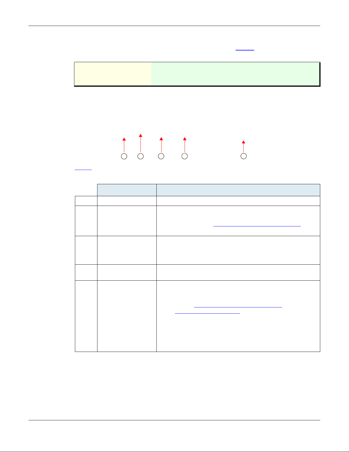
Front Indicators and Connectors
See “Indicators (LEDs)” on page 16 for a description of the LED patterns the Mediatrix 4400 may have and
the states they represent.
Figure 1
shows the five visual indicators located on the front of the Mediatrix 4400.
Figure 1: Front Panel Indicators
describes the LEDs on the front panel of the Mediatrix 4400.
Table 4
Table 4: Mediatrix 4400 Front LEDs
LED Description
1. ETH2 Provides the state of the network connected to the ETH2 connector.
2. Ready When lit, the Mediatrix 4400 is ready to initiate or receive a call. The unit does not
have to be registered to a server.
3. In-Use When lit, at least one of the BRI lines is in use.
4. ETH1 Provides the state of the network connected to the ETH1 connector.
5. Power When lit, power is applied to the Mediatrix 4400.
2
Mediatrix 4400 – Digital Gateway
Page 13
Mediatrix 4400 Connectors and Indicators Hardware Installation Guide
2
5
1
3 4
Rear Connectors
The Mediatrix 4400 has several connections that must be properly set. Figure 2 shows the rear panel of the
Mediatrix 4400.
Standards Supported • IEEE P802.3af DTE Power via MDI
• ITU-T I.430 Basic user-network interface - Layer 1
specification (section 9).
Figure 2: Rear Panel Connectors
Table 5
describes the rear panel connections (from left to right).
Table 5: Rear Connections of the Mediatrix 4400
Connection Description
1. Power connector External 12 Vdc power supply.
2. RESET/DEFAULT
button
Resets configuration parameters of the Mediatrix 4400 to default
(known) values. It can be used to reconfigure the unit.
Warning: Read Section “RESET/DEFAULT Button” on page 18 before
attempting to reset the unit.
3. ETH1 A 10/100 BaseT Ethernet RJ-45 connector for access to a LAN, WAN
or computer. The Mediatrix 4400 may also offer the option to use this
connector as a remote power feeding over Ethernet as per 802.3af
when the network offers the capability.
4. ETH2 A 10/100 BaseT Ethernet RJ-45 connector for access to a LAN, WAN
or computer.
5. BRI 1 – BRI 4
connectors
Up to four RJ-45 connectors to attach BRI lines.
• The Mediatrix 4402 and Mediatrix 4404 models offer an
optional metallic bypass relay between Connectors #1 and
#2. See “
Bypass Feature (Mediatrix 4402plus /
4404plusModels)” on page 4 for more details.
• The Mediatrix 4400plus models offer the option to use
Power Feeding over ISDN in NT mode as per ITU-T I.430
(section 9).
Note: Connectors 2, 3, and 4 are optional and not available on all
Mediatrix 4400 models.
Mediatrix 4400 – Digital Gateway
3
Page 14

Chapter 1 - Overview Port Numbering Convention
BRI connector state LED
BRI
Connector
#2
BRI
Connector
#3
BRI
Connector
#1
BRI
Connector
#4
The Mediatrix 4400 also has one indicator (LED) for each BRI connector. Table 6 describes these indicators.
Table 6: Rear Panel LEDs
LED Description
BRI Indicates the state of each BRI connector:
• Yellow LED: The connection has a Loss of Signal (LOS).
• Green LED: The connection works properly.
Port Numbering Convention
The following describes the BRI connectors numbering convention.
Note: Connectors 2, 3, and 4 are optional and not available on all Mediatrix 4400 models.
Figure 3: BRI Connectors Numbering Conventions
Bypass Feature (Mediatrix 4402plus / 4404plusModels)
In the event of a power failure or network failure, the optional bypass feature permits users to make and
receive calls even when the Mediatrix 4400 is not operating. The Mediatrix 4400 BRI 1 and BRI 2 connectors
may either act as a SCN bypass. For instance, if you decide to connect a SCN line into the BRI 2 connector,
you can use a BRI telephone connected into the BRI 1 connector to make calls.
Furthermore:
The connector on which the SCN line is connected must be configured as a TE.
The other connector must be configured as a NT.
Refer to the Software Configuration Guide for more details on how to configure the line type.
During normal operation, the direct connection between the BRI 1 and BRI 2 connectors is switched out
through commuting relays and both ports resume normal functions. When power is removed from the
Mediatrix 4400, the relay setting is restored to a connected state and the SCN line can be used as an
emergency line. Consequently, a BRI telephone used on the other port is directly connected to this SCN line.
When the power is restored, this automatically removes the Bypass connection; this means that any ongoing
call on the Bypass connection is terminated.
4
Mediatrix 4400 – Digital Gateway
Page 15

C HAPTER
2
This chapter describes the installation of the Mediatrix 4400.
Planning the Installation
Before installing the Mediatrix 4400, you should complete the following tasks:
Create a network diagram (see section “Network Diagram” on page 6).
Gather IP-related information (see section “IP-Related Information” on page 6 for more
information).
Install the hardware and software needed to configure the Mediatrix 4400 (see section
“Network Information” on page 6).
Installation Checklist
The installation checklist lists the tasks for installing the Mediatrix 4400. Print a copy of this checklist and mark
the entries as you complete each task. Include the completed checklist in your site log.
Mediatrix 4400 name/serial number _________________________________________________________
Installation
Figure 4: Installation Checklist
Task Verified By Date
Network information available & recorded in site log
Environmental specifications verified
Site power voltages verified
Installation site pre-power check completed
Required tools available
Additional equipment available
Mediatrix 4400 received
Quick start guide received
Regulatory compliance and safety information received
Warranty card received
Software version verified
Rack, desktop, or wall mounting of chassis completed
Initial electrical connections established
ASCII terminal attached to console port
Cable length limits verified
Initial configuration performed
Initial operation verified
Mediatrix 4400 – Digital Gateway
5
Page 16

Chapter 2 - Installation Safety Recommendations
Site Log
Media5 recommends that you maintain a site log to record all actions relevant to the Mediatrix 4400, such as:
Installation: Print a copy of the installation checklist and insert it into the site log.
Upgrades and maintenance: Use the site log to record ongoing maintenance and expansion
history. Update the site log to reflect the following:
• Configuration changes
• Maintenance schedules, requirements, and procedures performed
• Comments, notes, and problems
• Software changes and updates to firmware
Network Information
When planning the installation of the Mediatrix 4400, you should consider the following network information.
Network Diagram
It is always good practice to draw a network overview diagram that displays all neighbouring IP nodes, serial
connected elements, and other components. It is recommended that you keep a copy in the site log (see “Site
Log” on page 6 for more information on keeping a site log).
IP-Related Information
Before you can install the Mediatrix 4400, you need to have the following information:
IP addresses and subnet mask used for the Ethernet WAN connector
IP addresses of the central SIP server
IP addresses of the central server used for configuration upload and download
Power Source
If you suspect that your AC power is not reliable, for example if room lights flicker often or there is machinery
with large motors nearby, have a qualified professional test the power. Install a power conditioner if necessary.
Safety Recommendations
The following are safety recommendations and best practices to follow when working with the Mediatrix 4400.
Maintaining Safety with Electricity
Warning: Do not work on the Mediatrix 4400, connect or disconnect cables during periods of lightning
activity.
Warning: Disconnect all power before servicing the Mediatrix 4400.
Warning: Hazardous network voltages might be present in WAN, LAN, and telephone networks
connectors regardless of whether power to the device is OFF or ON. Use caution when working near these
connectors to avoid electric shock. When detaching cables, detach the end away from the Mediatrix 4400
first.
6
Mediatrix 4400 – Digital Gateway
Page 17

Required Mounting Tools and Equipment Hardware Installation Guide
General Safety Practices
Follow these guidelines to ensure personal safety and protect the equipment:
Keep the Mediatrix 4400 clear and dust-free during and after installation.
Locate the emergency power-off switch for the room in which you are working. Then, if an
electrical accident occurs, you can act quickly to turn off the power.
Disconnect all power before installing the Mediatrix 4400.
Do not work alone if potentially hazardous conditions exist.
Never assume that power is disconnected from a circuit. Always check.
Do not perform any action that creates a potential hazard to people or makes equipment
unsafe.
Warning: This equipment must be installed and maintained by service personnel. Incorrectly connecting
this equipment to a general-purpose outlet could be hazardous. The telecommunications lines must be
disconnected before unplugging the main power connector.
Preventing Electrostatic Discharge Damage
Wear an ESD-preventive wrist strap, ensuring that it makes good skin contact. Connect the clip to earth ground
to channel unwanted ESD voltages to ground safely.
Required Mounting Tools and Equipment
You will need the following tools and parts to properly install the Mediatrix 4400:
Screws and anchors for wall-mounting, if required.
• Four wood screws or other fasteners, for installing the chassis on a wall.
ESD-preventive wrist strap.
In addition, you might need the following external equipment:
Modem for remote access.
Unpacking and Inspection
If you haven’t already done so, unpack the Mediatrix 4400 device. Carefully remove it from the package and
packing material. The Mediatrix 4400 package contains the following items:
1 x Mediatrix 4400 unit
1 x power supply for the country in which you are using the Mediatrix 4400
2 x Ethernet RJ-45 cables for BRI connections (Mediatrix 4401)
3 x Ethernet RJ-45 cables for BRI connections (Mediatrix 4402)
5 x Ethernet RJ-45 cables for BRI connections (Mediatrix 4404)
1 x Bumpon
1 x Printed Flyer
You may also need additional 10/100 BaseT Ethernet RJ-45 cables.
TM
kit for desktop use
Mediatrix 4400 – Digital Gateway
7
Page 18

Chapter 2 - Installation Location and Mounting Requirements
Location and Mounting Requirements
Warning: To prevent fire or shock hazard do not expose the unit to rain or moisture.
The Mediatrix 4400 is suitable for use in an office environment where it can be placed in the same room or
cabinet where the PBX/telephony equipment is located. The unit can be wall-mounted, mounted on a standard
48.26 cm (19 in.) equipment rack, or free standing. In addition, the Mediatrix 4400 can be rack-mounted in a
wiring closet or equipment room.
Location
Install the Mediatrix 4400 in a well-ventilated location where it will not be exposed to high temperature or
humidity. Do not install the Mediatrix 4400 in a location exposed to direct sunlight or near stoves or radiators.
Excessive heat could damage the internal components.
When deciding where to position the Mediatrix 4400, ensure that:
The Mediatrix 4400 is accessible for future upgrade, maintenance and troubleshoo ting, and
cables can be easily connected.
The cabling is away from the following:
• Sources of electrical noise such as radios, transmitters, and broadband amplifiers.
• Power lines and fluorescent lighting fixtures.
• Water or moisture that could enter the casing of the Mediatrix 4400.
The airflow is not restricted around the Mediatrix 4400 or through the vents of the unit. The unit
requires a minimum of 25 mm (1 in.) clearance.
The operating temperature is between 0
The humidity is not over 85% and is non-condensing.
o
C and 40oC.
Wiring Requirements
Make sure that the telephone wiring, LAN and WAN cables reach the device and can be dressed in a manner
that is safe for the wiring, does not pull or create lateral stress on the connectors on the device, and does not
present a trip hazard to personnel working in the vicinity of the equipment. Do not connect any cable or wiring
at this time.
8
Mediatrix 4400 – Digital Gateway
Page 19

Location and Mounting Requirements Hardware Installation Guide
Front
Rear
Screw holes
Wall-Mounting
The Mediatrix 4400 has two screw holes on its bottom surface, allowing a single unit to be wall-mounted.
To wall-mount the Mediatrix 4400:
1. Disconnect all of the cables from the Mediatrix 4400 before mounting.
2. Ensure that the wall you are using is smooth, flat, dry and sturdy. Attach a piece of plywood,
approximately 250 mm x 200 mm x 12 mm (10 inches x 8 inches x 0.5 inches) securely to the wall,
if necessary.
3. Position the Mediatrix 4400 against the wall (or plywood) as illustrated in Figure 5
Figure 5: Bottom View - Wall Mounting Screw Holes
.
4. Mark the position of the screw holes on the wall. Drill the two holes and install two screws.
5. Place the screw holes of the Mediatrix 4400 over the screws installed in the previous step.
6. Proceed to “
Free Standing Unit
When installing the Mediatrix 4400 on a desk or table, it should be located at least 20 cm from your monitor,
computer casing or other peripherals, including speakers. Never put books or paper on the Mediatrix 4400.
You must also apply the Bumpon
These will stabilize the Mediatrix 4400 and offer skidding resistance.
Condensation
When bringing the unit into a warm environment from the cold, condensation may result that might be harmful
to the unit. If this occurs, allow the unit to acclimatize for an hour before powering it on.
Cleaning
To clean the Mediatrix 4400, wipe with a soft dry cloth. Do not use volatile liquids such as benzine and thinner
that are harmful to the unit casing.
For resistant markings, wet a cloth with a mild detergent, wring well and then wipe off. Use a dry cloth to dry
the surface.
You can position the Mediatrix 4400 any way you want.
Hardware Installation” on page 10.
TM
authoadhesive protective products to the bottom of the Mediatrix 4400.
Mediatrix 4400 – Digital Gateway
9
Page 20
Chapter 2 - Installation Hardware Installation
2 43
Hardware Installation
This section describes how to set the connectors of the Mediatrix 4400.
Caution: The Mediatrix 4400 must be installed on a circuit equipped with a breaker so that you can easily
power the unit off if required.
See “Appendix B - Cabling Considerations” on page 27 for more details on the cables the Mediatrix 4400 uses.
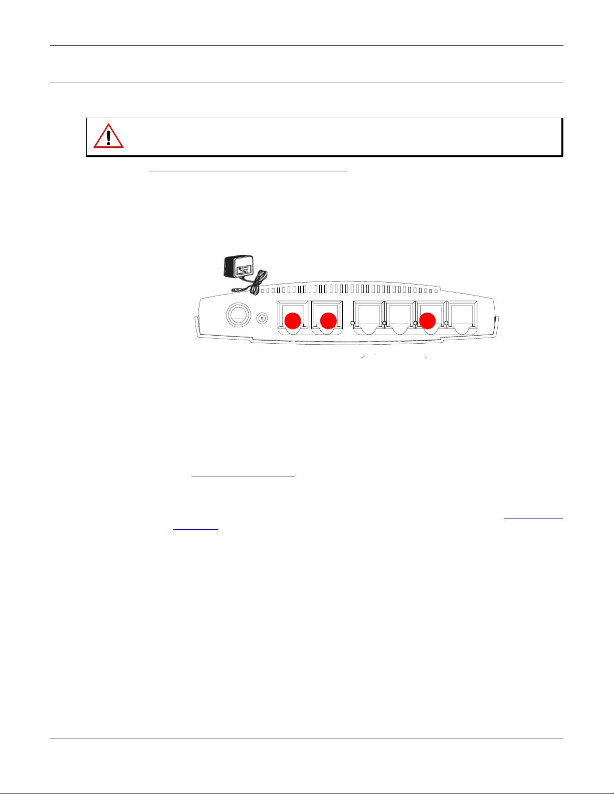
Connecting Cables
The following describes how to connect the various cables to the Mediatrix 4400.
Figure 6: Hardware Installation
Power Supply
To install the cables:
1. Before you begin, be sure that the Mediatrix 4400 is powered off.
2. Connect a 10/100 BaseT Ethernet RJ-45 cable into the ETH1 connector of the Mediatrix 4400.
The other end of the cable is connected to the WAN via a modem or other means.
See “RJ-45 Cable” on page 27
3. Connect a 10/100 BaseT Ethernet RJ-45 cable into the ETH2 connector of the Mediatrix 4400 and
connect the other end to the network card of a computer.
Use a standard telecommunication cord with a minimum of 26 AWG wire size. See “
on page 27 for more details.
4. Connect up to four BRI RJ-45 straight-through cables into any of the BRI connectors (labelled BRI
1, BRI 2, BRI 3, and BRI 4) (BRI connectors 2, 3, and 4 are optional and not available on all models).
If you are using the Mediatrix 4400 with a PBX, connect the other end of the cables to the PBX.
If you are using the Mediatrix 4400 with the PSTN, connect the other end of the cables to a proper
PSTN outlet.
If you are using the Mediatrix 4400 with ISDN telephones, connect the other end of the cables to
ISDN telephones. You have two choices to power your ISDN telephones.
ETH1 1 IRB2 IRB
/TESER
TLUAFED
cdV21
IP Network Connection
ETH2
4 IRB
BRI ISDN Connection
(PBX, PSTN, ISDN phones)
3 IRB
for more details on this cable.
RJ-45 Cable”
• Provide an alternate power feeding to the ISDN telephones. This could be by plugging
the telephones into a standard electrical outlet or by using an ISDN device that
provides power feeding such as an S-bus. This option depends on the type of
telephone you are using.
• Use the Mediatrix 4400’s ISDN Power Feeding feature if available. The versions of the
Mediatrix 4400 that provide ISDN power feeding are identified as the Mediatrix
4401plus, Mediatrix 4402plus, and Mediatrix 4404plus. This identification appears on
the label located on the bottom side of the unit. If you have such a unit, you can directly
10
Mediatrix 4400 – Digital Gateway
Page 21

Hardware Installation Hardware Installation Guide
connect your ISDN telephones. Note that not all ISDN telephones support this feature.
You must also enable the feature as described in the Software Configuration Guide.
Refer to “RJ-45 Cable” on page 27 for more details on this cable.
You are now ready to start the Mediatrix 4400.
Mediatrix 4400 – Digital Gateway
11
Page 22

Chapter 2 - Installation Hardware Installation
12
Mediatrix 4400 – Digital Gateway
Page 23
C HAPTER
3
Powering on the Mediatrix 4400
This chapter describes the initial provisioning of the Mediatrix 4400.
IP Address Discovery or Configuration
This section describes how to contact the Mediatrix 4400's management interface to start with unit
configuration.
Note that the Mediatrix 4400 IPv6 interface is disabled by default.
Once the physical connection is complete and the Mediatrix 4400 is powered up, you must first find out the IP
address the Mediatrix 4400 is using. The Mediatrix 4400' s IP address can be set either dynamically or
statically. The default behaviour of the Mediatrix 4400 is to try to obtain a dynamic IP address through a DHCP
server.
Dynamic IPv4 Address Discovery
The default configuration is set so that the unit can be directly plugged into a network and provisioned with a
DHCP server. Media5 strongly recommends to set your DHCP server before installing the unit on the network.
This way, you know the IP address associated with a particular unit.
Caution: If you set a Mediatrix 4400 with a static eth1-4 IPv4 address in a subnet (for instance,
192.168.200.1) and the eth5 interface receives a dynamic IP address in the same subnet (via a DHCP
server or PPP peer), you will not be able to contact the unit via the WAN. You must be careful that a dynamic
IP address does not overlap a static IP subnet that is already configured. Note that the current default value
of the Mediatrix 4400 is 192.168.0.10.
See the Software Configuration Guide for more details on how to set an external DHCP server.
Caution: If you are experiencing problems, or if you do not want to use a DHCP server and use a static IP
address instead, perform a Partial Reset procedure, as explained in “Partial Reset” on page 19.
DHCP servers generally allocate a range of IP addresses for use on a network and reserve IP addresses for
specific devices using a unique identifier for each device. The Mediatrix 4400 unique identifier is its media
access control (MAC) address. You can locate the MAC address as follows:
It is printed on the label located on the bottom side of the unit.
It is stored in the System Information page of the web interface.
If you have not reserved an IP address, you can discover which IP address has been assigned to the Mediatrix
4400 by either:
consulting your DHCP server's logs to find out details on the DHCP lease that was given to the
Mediatrix 4400.
using a network packet sniffer (e.g., Wireshark) to examine the DHCP messages exchanged
between the Mediatrix 4400 and your DHCP server while the Mediatrix 4400 boots up.
Mediatrix 4400 – Digital Gateway
13
Page 24
Chapter 3 - Powering on the M ediatrix 4400 IP Address Discovery or Configuration
To start the Mediatrix 4400 with a dynamic IP address:
1. If you need to discover the IP address of the Mediatrix 4400, install and start your network packet
sniffer.
2. Power on the Mediatrix 4400 by connecting the power cord to the unit and then connecting the other
end to an electrical outlet. If this is the very first time you are installing the Mediatrix 4400, it will
restart twice.
Warning: The electrical outlet must be installed near the Mediatrix 4400 so that it is easily accessible.
Note: If the Power LED is always blinking and never turns on, this means that the Mediatrix 4400 cannot
find a DHCP server. Check that you have a DHCP server properly configured on your network.
You can now access the Mediatrix 4400 web interface. Refer to the Software Configuration Guide
for more details.
Initial Provisioning Sequence
When starting the Mediatrix 4400 for the first time, it needs to be configured before it can support calls. This
process is known as provisioning. This sequence assumes that you have installed the Mediatrix 4400
hardware as per “
The Mediatrix 4400 requests its configuration only on the first restart. You can change the configuration at will
after the initial provisioning and the provisioning system can refresh the Mediatrix 4400 configuration.
Hardware Installation” on page 10.
Initial provisioning sequence:
1. When the Mediatrix 4400 starts, it broadcasts a message requesting DHCP services (if the unit is
configured to start in DHCP mode).
2. The DHCP server responds with a set of IP addresses and network parameters, one of which is the
Mediatrix 4400 IP address.
The following are some of the network parameters assigned via DHCP:
• Mediatrix 4400 IP address
• Subnet Mask
• Default Router IP address
• DNS IP addresses
• Configuration script server IP address and port number (optional)
• SIP Servers IP address and port number
3. The Mediatrix 4400 request its configuration by using a configuration file.
Default Static IPv4 Address Configuration
If there is no DHCP server in your network, then the IP address has to be configured statically.
To start the Mediatrix 4400 with a static IP address:
1. Power on the Mediatrix 4400 by connecting the power cord to the unit and then connecting the other
end to an electrical outlet. If this is the very first time you are installing the Mediatrix 4400, it will
restart twice.
Warning: The electrical outlet must be installed near the Mediatrix 4400 so that it is easily accessible.
2. Reconfigure the IP address of your computer to 192.168.0.11 and the Subnet Mask to
255.255.255.0. Restart the computer.
14
Mediatrix 4400 – Digital Gateway
Page 25

IP Address Discovery or Configuration Hardware Installation Guide
3. Insert a small, unbent paper clip into the RESET/DEFAULT hole located at the rear of the Mediatrix
4400.
The Power LED will start blinking, and after a few seconds, all the LEDS will start blinking. Release
the paper clip after all the LEDs start blinking and before they all stop blinking (between 7-11
seconds).
This procedure is called a partial reset. After a partial reset is performed, the Mediatrix 4400 uses
the default IP address 192.168.0.1/24. Refer to “Partial Reset” on page 19 for details on the partial
reset procedure.
The corresponding link-local IPv6 address is also available and printed on the sticker under the
Mediatrix 4400.
You can now access the Mediatrix 4400 web interface. Refer to the Software Configuration Guide
for more details.
IPv6 Link Local Address Configuration
If there is no DHCPv6 server or IPv6 router in your network, you can use the link local address to contact the
unit. Note that the Mediatrix 4400 IPv6 interface is disabled by default.
1. With a 10/100 Hub and two 10/100 BaseT Ethernet RJ-45 straight cables, connect both cables to
the Hub; one of them is connected into the connector. The other cable links the computer to the
Hub.
2. Power on the Mediatrix 4400 by connecting the other end of the power cord to an electrical outlet.
The electrical outlet must be installed near the Mediatrix 4400 so that it is easily accessi ble .
3. Insert a small, unbent paper clip into the RESET/DEFAULT hole located at the rear of the Mediatrix
4400.
The Power LED will start blinking, and after a few seconds, all the LEDS will start blinking. Release
the paper clip after all the LEDs start blinking and before they all stop blinking (between 7-11
seconds).
This procedure is called a partial reset. After a partial reset is performed, the Mediatrix 4400 enables
its link local IPv6 address. Refer to “Partial Reset” on page 19 for details on the partial reset
procedure.
The corresponding link-local IPv6 address is also available and printed on the sticker under the
Mediatrix 4400.
4. Proceed with accessing the Mediatrix 4400’s web interface by using the unit’s link local address.
The unit’s link local address is printed on a sticker under the unit.
The link local address can be determined by using the following pattern: [fe80::290:f8ff:feXX:XXXX]
where XXXXXX are the last 6 digits of the unit’s MAC address. Example: The link local address for
the Mediatrix 4400 with MAC address 00:90:F8:12:34:56 would be [fe80::290:f8ff:fe12:3456].
Note: On Windows, a scope ID needs to be added to the link local address ([fe80::290:f8ff:fe12:3456%11]).
You can find this number by executing the ‘ipconfig’ command in a command prompt. Note the number at
the end of the IPv6 default Gateway for the interface used to contact the unit.
On Linux, the scope identifier may be the link name or the interface number. The interface number can be
determined through the Linux command line.
Verifying the Installation
There are a few ways to verify that the Mediatrix 4400 is properly connected to the IP network and is working:
By contacting it with a SNMP browser
By contacting it via the CLI
By contacting it via a web browser
By pinging it
Mediatrix 4400 – Digital Gateway
15
Page 26

Chapter 3 - Powering on the M ediatrix 4400 Indicators (LEDs)
These procedures assume that you know the IP address of the Mediatrix 4400 you want to verify. If the
Mediatrix 4400 does not respond, do the following:
Verify that the WAN cable is securely connected to the Mediatrix 4400 and to the network
connector.
Be sure that you did not connect crossover network cables.
Verify the state of the IP network to ensure it is not down (the ETH1 or ETH2 LED should be
ON or blinking).
Indicators (LEDs)
The indicators (LEDs) of the Mediatrix 4400 are described in “Mediatrix 4400 Connectors and Indicators” on
page 2.
LED Patterns – Specific Conditions
Table 7 describes the different states a Mediatrix unit can have and their associated LED patterns.
Table 7: LED Patterns
Condition Description LED Pattern
RestartPending Triggered when the RESET/DEFAULT button is
pressed in the ResetPending state. The unit
prepares for a physical shutdown and restart.
RecoveryPending Triggered when the RESET/DEFAULT button is
pressed at start-time or for at least 7 seconds.
DefaultSettingsPending Triggered when the RESET/DEFAULT button is
not released while in ResetPending state.
At run time, if the RESET/DEFAULT button is
released within 5 seconds, the unit applies
default settings, otherwise the action is
cancelled and the unit goes back to the
operation mode state or it resets.
At start time, the unit stays in this state until the
RESET/DEFAULT button is released. The unit
then applies the default settings and restarts.
UpdateInProgress A firmware pack is downloaded into the unit
and written to persistent storage.
UpdateFailed Triggered after a failure of a firmware pack
download operation. After 4 seconds, the unit
restarts.
Power LED:
• blinking, 1Hz, 50%
duty
All other LEDs:
•OFF
All LEDs:
• blinking, 1Hz, 50%
duty
All LEDs:
• steady ON
All LEDs:
• cycling from left to
right, individually
blinking 1Hz, 33%
duty
All LEDs:
• blinking at 3Hz,
50% duty. One LED
out of two has a 180
degree phase. This
pattern lasts for 8
seconds.
16
Mediatrix 4400 – Digital Gateway
Page 27

Indicators (LEDs) Hardware Installation Guide
Table 7: LED Patterns (Continued)
Condition Description LED Pattern
Rescue Network
Enabled
BootOnRecoveryBank Triggered when the unit is booting on the
Automatic network
configuration in
progress
No network address set Triggered when the unit cannot be contacted
NetworkRescue The unit tries to download and install a firmware
Triggered after the user has performed a partial
reset procedure.
recovery bank and no update is pending.
Waiting for DHCP (IPv4 or IPv6) answer or IPv6
router advertisement or PPPoE connection.
because DHCP failed, PPP failed, and no static
interface is configured.
given by the Network Rescue server.
LED Patterns – Default Behaviour
When no specific condition matches those described in Table 7, the LEDs behave individually according to
the following rules:
Power and In Use LEDs:
• blinking
(synchronized)
1Hz, 75% duty
Power LED:
• blinking, 0.25Hz,
75% duty
All LEDs:
• Blinking green,
3Hz, 50% duty
Power LED:
• blinking, 3 Hz, 50%
duty.
Ready LED:
•Off
All other LEDs:
• blinking to show a
LED displacing light
from left to right and
right to left.
Table 8: Default LED Behaviour
Mediatrix 4400 – Digital Gateway
LED Type Condition Behaviour
RestartInProgress Blinking, 1 Hz, 50% duty
Power
RestartCompleted Steady ON
Network traffic Blinking, variable rate
ETH
No network traffic Steady ON
Network traffic Blinking, variable rate
ETH2
No network traffic Steady ON
Lines Idle and Unlocked Steady OFF
Lines InUse and Unlocked Steady ON
In Use
Shutting Down Steady yellow
Locked Blinking yellow, 1 Hz, 50% duty
17
Page 28

Chapter 3 - Powering on the M ediatrix 4400 RESET/DEFAULT Button
Table 8: Default LED Behaviour (Continued)
LED Type Condition Behaviour
Ready
RESET/DEFAULT Button
The RESET/DEFAULT button allows you to:
Cancel an action that was started.
Revert to known factory settings if the Mediatrix 4400 refuses to work properly for any reason
or the connection to the network is lost.
Reconfigure a unit.
At Run-Time
The RESET/DEFAULT button can be used at run-time – you can press the button while the Mediatrix 4400 is
running without powering the unit off. Table 9
All lines are enabled
(operational state).
All lines are disabled
(operational state).
At least one line is enabled
and at least one line is
disabled (operational state).
describes the actions you can perform in this case.
Table 9: RESET/DEFAULT Button Interaction
Steady ON
Steady OFF
Blink 0.25 Hz 75%
DEFAUL T Button
2 to 6 seconds Restarts the
7 to 11 seconds Sets the Mediatrix
12 to 16 seconds Restarts the
17 seconds and
more
At Start-Time
You can use the RESET/DEFAULT button at start-time – you power the unit off, and then depress the button
until the LEDs stop blinking and remain ON. This applies the “Factory Reset” procedure (see “
on page 20). This feature reverts the Mediatrix 4400 back to its default factory settings.
RESET/
Pressed for:
Action Comments LEDs Pattern
No changes are made to the
Mediatrix 4400
4400 in Partial Reset
Mode
Mediatrix 4400 in
Factory Reset
No action is taken The RESET/DEFAULT Button
Mediatrix 4400 settings.
Sets some of the Mediatrix 4400
configuration to pre-determined
values.
Deletes the persistent
configuration, creates a new
configuration file with the default
factory values, and then restarts
the unit.
Pressed event is ignored
Power LED:
• blinking, 1Hz,
All other LEDs:
•OFF
All LEDs
• blinking, 1Hz,
All LEDs
• steady ON
N/A
50% duty
50% duty
Factory Reset”
18
Mediatrix 4400 – Digital Gateway
Page 29

RESET/DEFAULT Button Hardware Installation Guide
Partial Reset
The Partial reset provides a way to contact the Mediatrix 4400 in a known and static state while keeping most
of the configuration unchanged.
Following a partial reset, the Mediatrix 4400 management interface is set to the Rescue interface. The default
address for this interface is 192.168.0.1/24 and has its corresponding link-local IPv6 available and printed on
the sticker under the Mediatrix 4400. Any existing network interface that conflicts with the Rescue interface
address is disabled.
You can contact the Mediatrix 4400 at this address to access its configuration parameters. It is not advised to
access the unit on a regular basis through the Rescue network interface. You should reconfigure the unit’s
network interfaces as soon as possible in order to access it through another interface. See “After a Partial
Reset” on page 19 for more details.
In a partial reset, the following services and parameters are also affected:
AAA service: User(s) from profile are restored with their factory password.
SNMP service: Resets the enableSnmpV1, enableSnmpV2, enableSnmpV3 and snmpPort
values to their default values.
WEB service: Resets the serverPort to its default value.
To trigger the Partial Reset:
1. Insert a small, unbent paper clip into the RESET/DEFAULT hole located at the rear of the Mediatrix
4400. While pressing the RESET/DEFAULT button, restart the unit.
Do not depress before all the LEDs start blinking (between 7-11 seconds).
2. Release the paper clip.
After a Partial Reset
Following a partial reset, you should:
1. Create or activate network interfaces as described in the Software Configuration Guide, Chapter
Interface Parameters, Section Interfaces Configuration. Do not disable the Rescue interface!
2. Change the Mediatrix 4400 system management network interface to something other than Rescue
as described in the Software Configuration Guide, Chapter Miscellaneous – Management Interface,
Section Management Interface Configuration.
Note that you must be able to cont act the interface you select in order to continue with the following
steps.
3. Contact the Mediatrix 4400 through the new system management network interface.
4. Disable the Rescue network interface as described in the Software Configuration Guide, Chapter
Interface Parameters, Section Interfaces Configuration.
Mediatrix 4400 – Digital Gateway
19
Page 30
Chapter 3 - Powering on the M ediatrix 4400 Management Choices
Factory Reset
The Factory reset reverts the Mediatrix 4400 back to its default factory settings. It deletes the persistent MIB
values of the unit, including:
The firmware pack download configuration files.
The SNMP configuration, including the SNMPv3 passwords and users.
The PPPoE configuration, including the PPP user names and passwords.
The Factory reset creates a new configuration file with the default factory values. It should be performed with
the Mediatrix 4400 connected to a network with access to a DHCP server. If the unit canno t find a DHCP
server, it sends requests indefinitely.
To trigger the Factory Reset:
1. Power the Mediatrix 4400 off.
2. Insert a small, unbent paper clip into the RESET/DEFAULT hole located at the rear of the Mediatrix
4400. While pressing the RESET/DEFAULT button, restart the unit.
Do not depress before the LEDs stop blinking and are steadily ON.
3. Release the paper clip.
The Mediatrix 4400 restarts.
This procedure resets all variables in the MIB modules to their default value.
When the Mediatrix 4400 has finished its provisioning sequence, it is ready to be used with a DHCP-
provided IP address and MIB parameters.
This procedure can also be performed at run-time.
Note: The Factory reset alters any persistent configuration data of the Mediatrix 44 00.
Management Choices
Congratulations for properly installing the Mediatrix 4400. You can now configure the software parameters of
the unit.
The Mediatrix 4400 offers various management options. All these options are described in the Dgw v2.0
Software Configuration Guide.
Management Choice Features
Web GUI The Mediatrix 4400 web interface allows you to configure the following information:
SNMPv1/2/3 The Mediatrix 4400 SNMP feature allows you to configure all the MIB services.
Command Line
Interface (CLI)
Table 10: Management Options
• Network attributes
• SIP parameters
• VoIP settings
• Management settings such as configuration scripts, restore / backup,
etc.
The Mediatrix 4400 CLI feature allows you to configure all the MIB services.
Unit Manager
Network
20
The UMN offers the following:
• Auto-discovery
• Group provisioning
• SNMP access and remote management.
Mediatrix 4400 – Digital Gateway
Page 31
A PPENDIX
A
This Appendix lists the various standards compliance of the Mediatrix 4400.
Standards Supported
The Mediatrix 4400 complies to the following standards:
Category Specification
Agency approvals • European Union, CE mark (Declaration of Conformity)
Safety standards • IEC 60950 (1st Edition 2001 With all national deviations)
Emissions • FCC Part 15:2004 Class B
Immunity EN55024:1998 including the followi ng (with amendments A1 and A2):
Telecom • TBR3:1995 (with amendments A1: 1997)
Standards Compliance and
Safety Information
Table 11: Standards Compliance
• EN55022 (2006) Class B
• EN61000-3-2 (2000) Harmonic current emissions
• EN61000-3-3 (1995) Voltage fluctuations and flicker (with amendment
A1)
• EN61000-4-2 (1995), ESD
• EN61000-4-3 (1996), Radiated RF
• EN61000-4-4 (1995), Burst Transients
• EN61000-4-5 (1995), Surge
• EN61000-4-6 (1996), Conducted RF
• EN61000-4-11 (1995), Voltage Dips and Interruptions
a
a. Clauses 9.2.1, 9.2.6, 9.2.7, 9.2.9, 9.2.10, 10.1 to 10. 6, 10.8, 10.10, 11.1 to 11.3, 11.4.2, 11.4.4, 11.4.5, 11.5
Note: The standards compliance of the Mediatrix 4400 are printed on a sticker located on the bottom of the
unit.
Mediatrix 4400 – Digital Gateway
21
Page 32

Appendix A - Standards Compliance and Safety Information Disclaimers
Disclaimers
The following are the disclaimers related to the Mediatrix 4400.
CE Marking
DECLARATION OF CONFORMITY
We Media5 Corporation, located at 4229 Garlock st. Sherbrooke, Québec, Canada J1L 2C8
declare that for the hereinafter mentioned product the presumption of conformity with the
applicable essential requirements of DIRECTIVE 1999/5/EC OF THE EUROPEAN
PARLIAMENT (RTTE DIRECTIVE) is given.
Any unauthorized modification of the product voids this declaration.
For a copy of the original signed Declaration Of Conformity please contact Media5 at the above address.
RoHS China
22
Mediatrix 4400 – Digital Gateway
Page 33

Translated Warning Definition Hardware Installation Guide
Translated Warning Definition
The following information provides an explanation of the symbols which appear on the Mediatrix 4400 and in
the documentation for the product.
Warning: Means danger. You are in a situation that could cause bodily injury. Before you work on any
equipment, you must be aware of the hazards involved with electrical circuitry and familiar with standard
practices for preventing accidents.
Waarschuwing: Dit waarschuwingssymbool betekent gevaar. U overtreat in een situatie die lichamelijk
letsel kan veroorzaken. Voordat u aan enige apparatuur gaat werken, dient u zich bewust te zijn van de bij
elektrische schakelingen betrokken risico's en dient u op de hoogte te zijn van standaard maatregelen om
ongelukken te voorkomen.
Varoitus: Tämä varoitusmerkki merkitsee vaaraa. Olet tilanteessa, joka voi johtaa ruumiinvammaan. Ennen
kuin työskentelet minkään laitteiston parissa, ota selvää sähkökytkentöihin li ittyvistä vaaroista ja
tavanomaisista onnettomuuksien ehkäisykeinoista.
Attention: Ce symbole d'avertissement indique un danger. Vous vous trouvez dans une situation pouvant
causer des blessures ou des dommages corporels. Avant de travailler sur un équipement, soyez conscient
des dangers posés par les circuits électriques et familiarisez-vous avec les procédures couramment utilisées
pour éviter les accidents.
Warnung: Dieses Warnsymbol bedeutet Gefahr. Sie befinden sich in einer Situation, die zu einer
Körperverletzung führen könnte. Bevor Sie mit der Arbeit an irgendeinem Gerät beginnen, seien Sie sich der
mit elektrischen Stromkreisen verbundenen Gefahren und der Standardpraktiken zur Vermeidung von
Unfällen bewußt.
Avvertenza: Questo simbolo di avvertenza indica un pericolo. La situazione potrebbe causare infortuni alle
persone. Prima di lavorare su qualsiasi apparecchiatura, occorre conoscere i pericoli relativi ai circuiti elettrici
ed essere al corrente delle pratiche standard per la prevenzione di incidenti.
Advarsel: Dette varselsymbolet betyr fare. Du befinner deg i en situasjon som kan føre til personskade. Før
du utfører arbeid på utstyr, må du vare oppmerksom på de faremomentene som elektriske kretser innebærer,
samt gjøre deg kjent med vanlig praksis når det gjelder å unngå ulykker.
Aviso: Este símbolo de aviso indica perigo. Encontra-se numa situação que lhe poderá causar danos físicos.
Antes de começar a trabalhar com qualquer equipamento, familiarize-se com os perigos relacionados com
circuitos eléctricos, e com quaisquer práticas comuns que possam prevenir possíveis acidentes.
¡Advertencia!: Este símbolo de aviso significa peligro. Existe riesgo para su integridad física. Antes de
manipular cualquier equipo, considerar los riesgos que entraña la corriente eléctrica y familiarizarse con los
procedimientos estándar de prevención de accidentes.
Varning!: Denna varningssymbol signalerar fara. Du befinner dig i en situation som kan leda till
personskada. Innan du utför arbete på någon utrustning måste du vara medveten om farorna med elkretsar
och känna till vanligt förfarande för att förebygga skador.
Mediatrix 4400 – Digital Gateway
23
Page 34
Appendix A - Standards Compliance and Safety Information Safety Warnings
Safety Warnings
This section lists the following safety warnings:
Circuit Breaker (15A) Warning
TN Power Warning
Product Disposal Warning
No. 26 AWG Warning
LAN Connector Warning
ISDN BRI Connector Warning
Socket Outlet Warning
Circuit Breaker (15A) Warning
Warning: This product relies on the building's installation for short-circuit (overcurrent) protection. Ensure
that a fuse or circuit breaker no larger than 120 VAC, 15A U.S. (240 VAC, 10A international) is used on the
phase conductors (all current-carrying conductors).
TN Power Warning
Warning: The device is designed to work with TN power systems.
Product Disposal Warning
Warning: Ultimate disposal of this product should be handled according to all national laws and
regulations.
No. 26 AW G Warning
Warning: To reduce the risk of fire, use only No. 26 AWG or larger telecommunication line cord.
LAN Connector Warning
Warning: Do not connect the LAN connector directly to the Public Switched Telephone Network (PSTN),
to an off premise application, an out of plant application, any exposed plant application, or to any equipment
other than the intended application, connection may result in a safety hazard, and/or defective operation
and/or equipment damage.
Exposed plant means where any portion of the circuit is subject to accidental contact with electric lighting or
power conductors operating at a voltage exceeding 300V between conductors or is subject to lightning
strikes.
ISDN BRI Connector Warning
Warning: Do not connect the ISDN BRI connectors directly to an off premise application, an out of plant
application, any exposed plant application, or to any equipment other than the intended application,
connection may result in a safety hazard, and/or defective operation and/or equipment damage.
24
Mediatrix 4400 – Digital Gateway
Page 35
Safety Recommendations Hardware Installation Guide
Socket Outlet Warning
Warning: The socket outlet, if used, shall be located near the equipment and shall be easily accessible by
the user.The AC adaptor inlet is considered as disconnection device. The device must be readily
operational.
Safety Recommendations
To insure general safety follow these guidelines:
Do not open or disassemble this product.
Do not get this product wet or pour liquids into it.
Do not perform any action that creates a potential hazard to people or makes the equipment
unsafe.
Caution: When using this equipment, basic safety precautions should always be followed to reduce the
risk of fire, electric shock and injury to persons, including the following:
• Do not use this product near water, for example, near a bath tub, wash bowl, kitchen sink or laundry
tub, in a wet basement or near a sw imming pool.
• Avoid using a telephone (other than a cordless type) during an electrical storm. There may be a remote
risk of electric shock from lightning.
• Do not use the telephone to report a gas leak in the vicinity of the leak.
Mediatrix 4400 – Digital Gateway
25
Page 36

Appendix A - Standards Compliance and Safety Information Safety Recommendations
26
Mediatrix 4400 – Digital Gateway
Page 37
A PPENDIX
1
2
3
4
5
6
7
8
B
This Appendix describes the pin-to-pin connections for cables used with the Mediatrix 4400.
RJ-45 Cable
The RJ-45 connector is commonly used for network cabling and for telephony applications. It is used to wire
both ends identically so the signals pass straight through.
RJ-45 cabling is also known as Twisted-pair Ethernet (TPE), Unshielded twisted pair (UTP) and 10/100
Base-T.
Cabling Considerations
Warning: To reduce the risk of fire, use only No. 26 AWG or larger telecommunication line cord.
Figure 7: RJ-45 Cable
When connecting an Ethernet cable to the Mediatrix 4400, use a standard telecommunicatio n cord with a
minimum of 26 AWG wire size. It is possible to use either a crossover or straight Ethernet cable to connect in
the Ethernet connectors. These connectors perform automatic MDI / MDIX detection, meaning that they adapt
to the type of cable connected to them.
The auto MDI / MDIX feature works only when the connectors are configured in auto detect mode, which is
the default mode.
Whenever you force the Mediatrix 4400 to use a specific Ethernet mode (for example 100 Mb Full Dup lex),
the type of cable to use depends on the other peer. For example, a straight cable is required to connect the
Mediatrix 4400 to a hub or a switch, while a crossover cable is required to connect the Mediatrix 4400 to a PC.
Mediatrix 4400 – Digital Gateway
27
Page 38
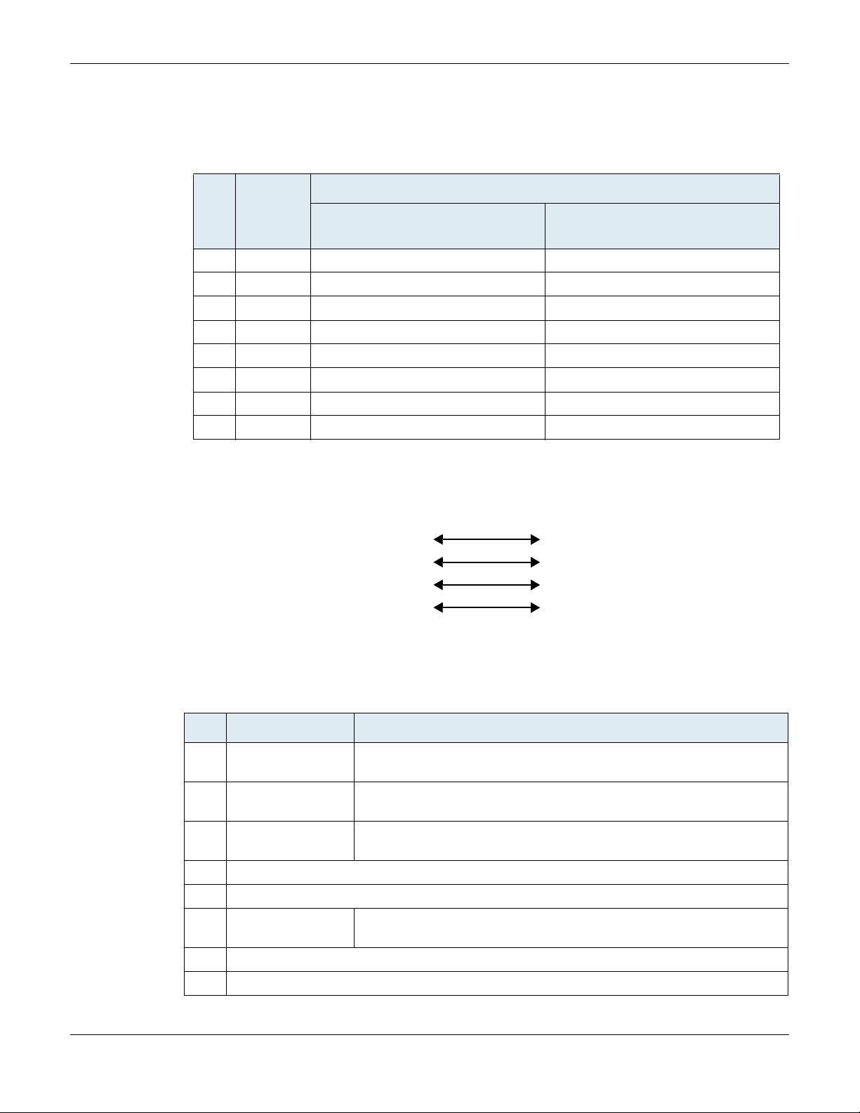
Appendix B - Cabling Considerations RJ-45 Cable
Pin 1
Pin 2
Pin 3
Pin 6
Pin 1
Pin 2
Pin 3
Pin 6
Straight Through Cable
A RJ-45 straight through cable is used to connect a computer to a network device. For instance, you must use
straight through cables to connect a computer to a network hub, switch, and router.
Table 12: RJ-45 Pinout Information
Colour Coding
Pin # Function
EIA/TIA 568A
1 Transmit + White with green stripe White with orange stripe
2 Transmit - Green with white stripe or solid green Orange with white stripe or solid orange
3 Receive + White with orange stripe White with green stripe
4 N/A Blue with white stripe or solid blue Blue with white stripe or solid blue
5 N/A White with blue stripe White with blue stripe
6 Receive - Orange with white stripe or solid orange Green with white stripe or solid green
7 N/A White with brown stripe or solid brown White with brown stripe or solid brown
8 N/A Brown with white stripe or solid brown Brown with white stripe or solid brown
EIA/TIA 568B
AT&T 258A
The RJ-45 cable uses two pairs of wires: one pair for transmission and the second pair for reception. It is wired
so that pins 1 & 2 are on one twisted pair and pins 3 & 6 are on a second pair according to common wiring
standards which meet the EIA/TIA T568A and T568B requirements.
Figure 8: Straight Through Connectivity
Pin Name and Function
The following is the function of each pin in a RJ-45 cable.
Table 13: Pin Name and Function
Pin # Name Function
1 Transmit Data Plus Positive signal for the TD differential pair. This signal contains the serial
output data stream transmitted onto the network.
2 Transmit Data Minus Negative signal for the TD differential pair. This contains the same output as
pin 1.
3 Receive Data Plus Positive signal for the RD differential pair. This signal contains the serial
input data stream received from the network.
4 not connected
5 not connected
6 Receive data minus Negative signal for the RD differential pair. This signal contains the same
input as pin 3.
7 not connected
8 not connected
28
Mediatrix 4400 – Digital Gateway
Page 39

RJ-45 Cable Hardware Installation Guide
1- TX+
2- TX3- RC+
6- RC-
TX+ -1
TX- -2
RC+ -3
RC- -6
Crossover Cable
A RJ-45 crossover cable is used when only two systems are to be connected to each other, peer to peer, at
the Ethernet Cards by “crossing over” (reversing) their respective pin contacts. An example would be
connecting two computers together to create a network. The crossover eliminates the need for a hub when
connecting two computers. A crossover cable may also be required when connecting a hub to a hub, or a
transceiver to transceiver or repeater to repeater. When connecting a hub to a transceiver, a straight through
cable is always used.
Note: This is not an IEEE supported configuration and should be used for test purposes only.
A crossover cable is sometimes called a null modem. The coloured wires at either end are put into different
pin numbers, or crossed over.
Figure 9: Crossover Connectivity
Mediatrix 4400 – Digital Gateway
29
Page 40

Appendix B - Cabling Considerations RJ-45 Cable
30
Mediatrix 4400 – Digital Gateway
Page 41

A PPENDIX
C
Standard Hardware Information
The specifications and information regarding this product are subject to change without notice. Every effort is
made to ensure the accuracy of this document. Because of ongoing product improvements and revisions,
Media5 cannot guarantee its accuracy, nor can be responsible for errors or omissions. Please contact your
Media5 sales representative to obtain the latest version of the technical specifications.
Industry Standard Protocols
The Mediatrix 4400 has been designed to support all major industry standards used today, as well as those
that will eventually be implemented at a later date. Because of this specific design characteristic, the Mediatrix
4400 can be integrated with existing telephone, fax and data equipment such as PCs and routers.
Parameter Description
Vocoders • G.711 (a-law, u-law) with optional VAD support
Table 14: Industry Standard Protocols
• G.723.1a
•G.726
• G.729a
• G.729ab
IP Telephony Protocols • SIP - RFC 3261, RFC 3262, RFC 3263
Real-Time Transport Protocols • RTP/RTCP - RFC 1889, RFC 1890, RFC 2833, RFC 3389
Network Management
Protocols
Data Features • PPPoE client - RFC 1332, RFC 1661, RFC 1334, RFC 1994,
QoS • ToS
•SNMPv3
• DHCP - RFC 2131, RFC 2132
• TFTP - RFC 1350
• Syslog - RFC 3164
• HTTP 1.0 - RFC 1945
• HTTP 1.1 - RFC 2616
• HTTPS
• Basic and digest HTTP authentication - RFC 2617
RFC 2516, RFC 1471, RFC 1472, RFC 1473, RFC 1877.
Note: some PPPoE RFCs are implemented partially.
• TFTP or HTTP auto-provisioning
• DHCP server
• NAPT
• DiffServ
•802.1p
•802.1Q
Mediatrix 4400 – Digital Gateway
31
Page 42

Appendix C - Standard Hardware Information Hardware Features
Table 14: Industry Standard Protocols (Continued)
Parameter Description
Voice Signalling • Euro ISDN EDSS-1 / ETSI BRI/NET3
• ETS 300 012-1 (ITU-T I.430)
• ETS 300 402-2 (ITU-T Q.921)
• ETS 300 403-1/2 (ITU-T Q.931)
• ETS 300 102-2 (ITU-T Q.931)
• ETS 300 402-1 (ITU-T Q.921)
• ETS 300 403-2 (ITU-T Q.931)
• ETS 300 102-1 (ITU-T Q.931)
• ISDN speech, audio and data (Fax Gr 4, UDI 64, RDI 64)
• ECMA-143 (QSIG-BC)
Hardware Features
Interfaces
2 x RJ-45 WAN connectors, 10/100 BaseT Ethernet access
Up to 4 RJ-45 BRI connectors for ISDN connectivity
Power
External 12 Vdc power supply (wall plug or desktop, based on country/area model).
Product Architecture Details
Supports multiple concurrent communications using any vocoders.
DSP-based DTMF detection and generation.
DSP-based fax relay.
Embedded IPv4 TCP/IP stack with configurable QoS implemented by:
• ToS byte at Network layer 3
• 802.1p at Data Link layer 2
Network parameters assigned via DHCP
Real Time Fax Router Technical Specifications
Automatic selection between voice and fax.
Table 15: Fax Technical Specifications
Parameter Description
Ethernet 10/100 BaseT Ethernet
Data Link Ethernet
Network IP (Internet Protocol)
32
Mediatrix 4400 – Digital Gateway
Page 43

Audio Specifications Hardware Installation Guide
Table 15: Fax Technical Specifications (Continued)
Parameter Description
Transport TCP / UDP
Protocols Group 3 Fax
Clear channel (G.711) or T. 38 Real Time Fax Over IP protocol Stack
Fax Data Compression MH
Fax Transmission Up to 14.4 kbps
Audio Specifications
Software-adjustable dynamic and static jitter buffer protection.
Programmable by country: Call progress tone generation including dial tone, busy tone,
ringback and error tones.
Silence detection/suppression level software adjustable.
DTMF Tone Detection
Parameter Description
16-Digit DTMF Decoding 0 to 9, *, #, A, B, C, D
Permitted Amplitude Tilt High frequency can be +2 dB to -8 dB relative to low frequency
Dynamic Range -35 dBm to +3 dBm per tone
Frequency Accept ± 1.5% of nominal frequencies
Minimum Tone Duration 40 ms
Interdigit Timing Detects like digits with a 40 ms interdigit delay
DTMF Tone Generation
Parameter Description
Per Frequency Nominal -6 dBm to -4 dBm
Frequency Deviation Less than 1%
Table 16: DTMF Tone Detection
Table 17: DTMF Tone Generation
Mediatrix 4400 – Digital Gateway
33
Page 44

Appendix C - Standard Hardware Information Power Consumption
Power Consumption
Table 18: Power Consumption
MTBF Value
The Mean Time Before Failure (MTBF) value of the Mediatrix 4400 models is estimated as follows:
These values are at 25 degrees Celsius ambient temperature. It has been defined using RelCalc v5.0, Bellcore
method (LimitedStress - Method I, Case 3), Desktop unit without the external power supply.
Mediatrix
Model
44xx
44xxplus
Voltage/
Frequency
120Vac / 60Hz all channels active 90 4.5 11 4.5
240Vac / 50Hz all channels active 60 5 14 5
12Vdc all channels active 290 3.5 3.5 3.5
120Vac / 60Hz all channels active,
240Vac / 50Hz all channels active,
12Vdc all channels active,
Operating
Condition
4W load
4W load
4W load
Mediatrix 4400 standard models: 275,000 hours
Mediatrix 4400plus models: 200,000 hours
Current
(mA)
205 12.5 25 8.5
13013319
85010106
Power (W) VA
Thermal
Dissipatio
n (W)
Operating Environment
Parameter Description
Operating Temperature 0°C to 40°C
Humidity Up to 85%, non-condensing
Storage -20°C to +70°C
Dimensions and Weight
Parameter Description
Dimensions Height: 4.9 cm (1.9 in)
Table 19: Operating Environment
Table 20: Dimensions and Weight
Width: 22 cm (8.7 in)
Depth: 17.6 cm (6.9 in)
34
Mediatrix 4400 – Digital Gateway
Page 45

Warranty Hardware Installation Guide
Table 20: Dimensions and Weight (Continued)
Parameter Description
Weight Mediatrix 4401/4402/4404: 458g (1.0 lb)
Mediatrix 4401plus/4402plus/4404plus= 514g (1.1 lb)
Warranty
All Media5 products carry Media5 Corporation's standard three-year hardware and software warranty. An
extended warranty is available.
Mediatrix 4400 – Digital Gateway
35
Page 46

Appendix C - Standard Hardware Information Warranty
36
Mediatrix 4400 – Digital Gateway
Page 47

A PPENDIX
D
10 BaseT
An Ethernet local area network that works on twisted pair wiring.
100 BaseT
A newer version of Ethernet that operates at 10 times the speed of a 10 BaseT Ethernet.
Basic Rate Interface (BRI)
An Integrated Services Digital Network configuration defined in the physical layer standard I.430 produced by
the ITU. This configuration consists of two 64 kbit/s “bearer” channels (B ch annels) and one 16 kbit/s “data”
channel (D channel). The B channels are used for voice or user data, and the D channel is used for any
combination of: data, control/signalling and X.25 packet networking. The two B channels can be bonded
together giving a total data rate of 128 kbit/s. BRI is the kind of ISDN interface most likely to be found in
residential service.
Domain Name Server (DNS)
Internet service that translates domain names into IP addresses. To use a domain name, a DNS service must
translate the name into the corresponding IP address. For instance, the domain name www.example.com
might translate to 198.105.232.4.
Dual-Tone Multi-Frequency (DTMF)
In telephone systems, multi-frequency signalling in which a standard set combinations of two specific voice
band frequencies, one from a group of four low frequencies and the other from a group of four higher
frequencies, are used. Although some military telephones have 16 keys, telephones using DTMF usually have
12 keys. Each key corresponds to a different pair of frequencies. Each pair of frequencies corresponds to one
of the ten decimal digits, or to the symbol “#” or “*”, the “*” being reserved for special purposes.
Glossary
Dynamic Host Configuration Protocol (DHCP)
TCP/IP protocol that enables PCs and workstations to get temporary or permanent IP addresses (out of a pool)
from centrally-administered servers.
Federal Communications Commission (FCC)
U.S. government regulatory body for radio, television, interstate telecommunications services, and
international services originating in the United States.
Gateway
A device linking two different types of networks that use different protocols (for example, between the packet
network and the Public Switched Telephone Network).
Integrated Services Digital Network (ISDN)
A set of digital transmission protocols defined by the international standards body for telecommunications, the
ITU-T (formerly called the CCITT). These protocols are accepted as standards by virtually every
telecommunications carrier all over the world.
ISDN complements the traditional telephone system so that a single pair of telephone wires is capable of
carrying voice and data simultaneously. It is a fully digital network where all devices and applications present
themselves in a digital form.
Mediatrix 4400 – Digital Gateway
37
Page 48

Appendix D - Glossary International Telecommunication Union (ITU)
International Telecommunication Union (ITU)
Organization based in Geneva, Switzerland, that is the most important telecom standards-setting body in the
world.
Internet Protocol (IP)
A standard describing software that keeps track of the Internet’s addresses for different nodes, routes outgoing
messages, and recognizes incoming messages.
Light Emitting Diode (LED)
A semiconductor diode that emits light when a current is passed through it.
Local Area Network (LAN)
Data-only communications network confined to a limited geographic area, with moderate to high data rates.
See also WAN.
Media Access Control (MAC) Address
A layer 2 address, 6 bytes long, associated with a particular network device; used to identify devices in a
network; also called hardware or physical address.
Network
A group of computers, terminals, and other devices and the hardware and software that enable them to
exchange data and share resources over short or long distances. A network can consist of any combination
of local area networks (LAN) or wide area networks (WAN).
Private Branch Exchange (PBX)
A small to medium sized telephone system and switch that provides communications between onsite
telephones and exterior communications networks.
Protocol
A formal set of rules developed by international standards bodies, LAN equipment vendors, or groups
governing the format, control, and timing of network communications. A set of conventions dealing with
transmissions between two systems. Typically defines how to implement a group of services in one or two
layers of the OSI reference model. Protocols can describe low-level details of machine-to-machine interfaces
or high-level exchanges between allocation programs.
Public Switched Telephone Network (PSTN)
The local telephone company network that carries voice data over analog telephone lines.
Router
A specialized switching device which allows customers to link different geographically dispersed local area
networks and computer systems. This is achieved even though it encompasses different types of traffic under
different protocols, creating a single, more efficient, enterprise-wide network.
Switched Circuit Network (SCN)
A communication network, such as the public switched telephone network (PSTN), in which any user may be
connected to any other user through the use of message, circuit, or packet switching and control devices.
Server
A computer or device on a network that works in conjunction with a client to perform some operation.
Session Initiation Protocol (SIP)
A protocol for transporting call setup, routing, authentication, and other feature messages to endpoints within
the IP domain, whether those messages originate from outside the IP cloud over SCN resources or within the
cloud.
38
Mediatrix 4400 – Digital Gateway
Page 49

Subnet Hardware Installation Guide
Subnet
An efficient means of splitting packets into two fields to separate packets for local destinations from packets
for remote destinations in TCP/IP networks.
Transmission Control Protocol/Internet Protocol (TCP/IP)
The basic communication language or protocol of the Internet. It can also be used as a communications
protocol in a private network (either an intranet or an extranet).
V o ice Over IP (VoIP)
The technology used to transmit voice conversations over a data network using the Internet Protocol. Such
data network may be the Internet or a corporate Intranet.
Wide Area Network (WAN)
A large (geographically dispersed) network, usually constructed with serial lines, that covers a large
geographic area. A WAN connects LANs using transmission lines provided by a common carrier.
Mediatrix 4400 – Digital Gateway
39
Page 50

Appendix D - Glossary Wide Area Network (WAN)
40
Mediatrix 4400 – Digital Gateway
Page 51

A PPENDIX
E
List of Acronyms
AWG American Wire Gauge
BRI Basic Rate Interface
CE Cummunauté européenne (French)
DHCP Dynamic Host Configuration Protocol
DNS Domain Name Server
IETF Internet Engineering Task Force
LAN Local Area Network
LED Light Emitting Diode
MAC Media Access Control
MDI Media Dependent Interface
MDIX Media Dependent Interface Crossover
PBX Private Branch eXchange
PSTN Public Switched Telephone Network
RFC Request for Comment
SCN Switched Circuit Network
SIP Session Initiation Protocol
TPE Twisted-Pair Ethernet
UTP Unshielded Twisted pair
VoIP Voice over Internet Protocol
WAN Wide Area Network
Mediatrix 4400 – Digital Gateway
41
Page 52

Appendix E - List of Acronyms
42
Mediatrix 4400 – Digital Gateway
Page 53

Index
Numerics
10 BaseT 3, 10, 27
37
defined
see also cabling
100 BaseT
3, 10, 27
37
defined
see also cabling
A
acronyms 41
audience, intended
auto MDI/MDIX
viii
27
B
Bypass connection, in BRI 4
C
cables, connecting 10
cabling
RJ-45
crossover
pin name
pinout information
straight through
see also 10 BaseT
see also 100 BaseT
cleaning the unit
compliance to standards. see standards compliance
condensation
connecting
cables during installation
unit
10
connectors
BRI ports
ETH1
3
3
ETH2
2
front
rear
3
RESET/DEFAULT
universal power supply unit
crossover cable. see cabling
customer services
29
28
28
28
9
9
10
3
3
3
x
D
document
conventions
objectives
structure
documentation
Media5 download portal
Mediatrix download portal
where to obtain
ix
vii
viii
x
x
x
E
end user technical support x
F
factory reset
reverting to
see also partial reset
front
connectors
indicators
20
2
2
H
humidity level 8
I
indicators
2
front
3
rear
inspecting the contents
installation
cables, connecting
checklist
connecting the hardware
default static IP address configuration
dynamic IP address discovery
free standing unit
network information
proper location
provisioning sequence, initial
required tools and equipment
reserving IP address
safety recommendations
selecting site for
setting up the unit for the first time
site log
verifying
wall-mounting
wiring requirements
intended audience
5
6
15
7
10
10
9
6
8
13
6
8
9
8
viii
K
key features 1
L
LAN
15
cable
defined
38
LEDs
38
defined
states
16
location, defining for installation
M
MAC address 13
38
defined
MDI/MDIX, auto
Media5 download portal
Mediatrix download portal
mounting, on a wall
27
x
x
9
14
13
14
7
13
8
Mediatrix 4400 – Digital Gateway
43
Page 54

Index
O
objectives of document vii
operating temperature
overview of the product
8
1
P
partial reset 19
see also factory reset
power feeding over Ethernet
power feeding over ISDN
product models
product overview
provisioning, initial sequence
1
1
3
3
14
R
rear
connectors
indicators
related documentation
Reset, partial reset procedure
reset, factory reset procedure
RJ-45. see cabling
3
3
viii
19
20
S
safety
recommendations
warnings
Circuit Breaker (15A)
LAN Connector
No. 26 AWG
Product Disposal
Socket Outlet
TN Power
site, selecting for unit
standards compliance
agency approvals
CE marking
emissions
immunity
RoHS China
safety standards
telecom
standards supported
straight through cable. see cabling
support services
21
21
25
24
24
24
24
25
24
8
21
22
21
22
21
ix
x
W
wall-mounting the unit 9
wiring, requirements for installation
8
T
technical support for end user x
temperature, operating
TPE. see cabling
translated warning definition
8
23
U
unpacking the contents 7
using this manual
UTP. see cabling
ix
V
verifying the installation 15
44
Mediatrix 4400 – Digital Gateway
 Loading...