

Page 1
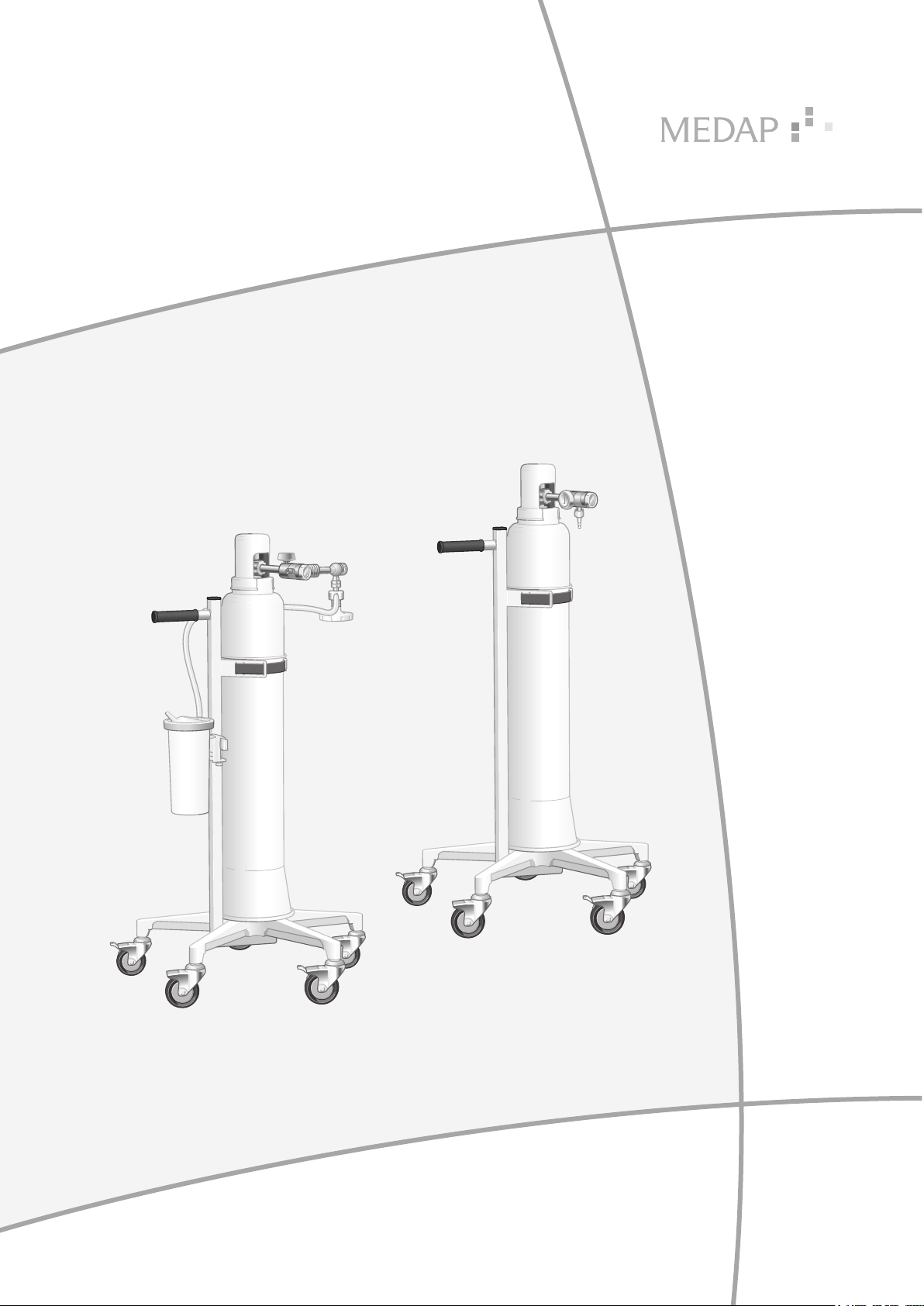
OPERATING INSTRUCTIONS
OXYRATOR
OXYRATOR WITH ASPIRATOR
GA 5752 5555 GB 05
Page 2

Subject to technical modification!
Illustrations and technical specifications may vary slightly from those in these Operating
Instructions as a result of ongoing product development.
V05 2019-12
2
GA 5752 5555 GB 05
Page 3

Table of contents
Table of contents
1 Introduction ..............................................................................................................................................5
1.1 Foreword .................................................................................................................................................... 5
1.2 How to use these operating instructions .................................................................................................... 5
1.2.1 Abbreviations ...............................................................................................................................5
1.2.2 Symbols .......................................................................................................................................5
1.2.2.1 Cross-references ....................................................................................................... 5
1.2.2.2 Actions and responses .............................................................................................. 5
1.2.3 Definitions ....................................................................................................................................6
1.2.3.1 Design of safety notes ............................................................................................... 6
1.2.3.2 Structure of notes ......................................................................................................6
1.2.4 Symbols used ..............................................................................................................................6
1.3 Disposal ......................................................................................................................................................7
1.3.1 Packaging ....................................................................................................................................7
1.3.2 ATMOS products .......................................................................................................................... 7
1.4 Overview of Oxyrator (REF 5752 5548) ..................................................................................................... 8
1.5 Overview of Oxyrator with aspirator (REF 5752 5549) ............................................................................... 9
1.6 Basic requirements .....................................................................................................................................9
1.6.1 Use in accordance with the intended purpose ............................................................................. 9
1.6.2 Applicable standards ..................................................................................................................10
1.6.3 Treatment system as per Article 12 ............................................................................................ 10
1.6.4 Intended purpose ....................................................................................................................... 10
1.6.5 Interface description of Oxyrator ................................................................................................ 12
1.6.5.1 Oxygen cylinder ....................................................................................................... 12
1.6.5.2 Connection tube ......................................................................................................12
1.6.5.3 Bubble humidifier (REF 5752 5315) ........................................................................ 12
1.6.6 Interface description of Oxyrator with aspirator ......................................................................... 12
1.6.6.1 Oxygen cylinder ....................................................................................................... 12
1.6.6.2 Vacuum connection tube ......................................................................................... 12
1.6.6.3 Suction tube .............................................................................................................13
1.6.6.4 Connection tube ......................................................................................................13
1.6.6.5 Bubble humidifier (REF 5752 5315) ........................................................................ 13
2 Safety notes ............................................................................................................................................14
3 Initial operation .......................................................................................................................................15
3.1 General .....................................................................................................................................................15
3.2 Connecting the pressure regulator ........................................................................................................... 15
GA 5752 5555 GB 05
3
Page 4

Table of contents
3.3 Oxyrator (REF 5752 5548) ....................................................................................................................... 16
3.3.1 Oxygen supply via tube adapter ................................................................................................ 16
3.3.2 Connecting accessories (optional) ............................................................................................. 17
3.3.2.1 Connection of bubble humidifier (REF 5752 5315) ................................................. 17
3.3.2.2 Connection of disposable humidifiers from other manufacturers ............................ 17
3.4 Oxyrator with aspirator (REF 5752 5549) ................................................................................................. 18
3.4.1 Connecting the fine regulator ..................................................................................................... 18
3.4.2 Connecting the gas-jet pump ..................................................................................................... 18
3.4.3 Mounting the tubes ....................................................................................................................19
3.4.4 Aspiration and oxygen therapy .................................................................................................. 19
3.4.4.1 Oxygen supply via tube adapter .............................................................................. 19
3.4.4.2 Connecting accessories (optional) .......................................................................... 20
4 Operation ................................................................................................................................................22
4.1 Function test ............................................................................................................................................. 22
4.2 Check the filling level of the oxygen cylinder............................................................................................ 22
4.3 Oxygen extraction ....................................................................................................................................23
4.4 Setting the vacuum level (only for Oxyrator with aspirator) ...................................................................... 23
5 Taking the unit out of operation ............................................................................................................ 24
5.1 Stopping oxygen extraction ...................................................................................................................... 24
5.2 Replacing the oxygen cylinder .................................................................................................................24
5.3 Oxyrator with aspirator ............................................................................................................................. 26
5.3.1 Detaching tubes ......................................................................................................................... 26
6 Cleaning and disinfection ......................................................................................................................27
6.1 General .....................................................................................................................................................27
7 Maintenance ............................................................................................................................................28
7.1 General .....................................................................................................................................................28
7.2 Periodic tests ............................................................................................................................................ 28
7.3 Visual and functional inspections .............................................................................................................28
7.4 Malfunctions and troubleshooting.............................................................................................................29
7.5 Repairs ..................................................................................................................................................... 29
7.6 Service hotline .......................................................................................................................................... 30
7.7 Sending in the device ............................................................................................................................... 30
8 Technical specifications ........................................................................................................................ 31
8.1 Ambient conditions ................................................................................................................................... 31
8.2 Technical specifications ............................................................................................................................ 31
8.3 Dimensions and weights ..........................................................................................................................31
9 Approved accessories ...........................................................................................................................32
9.1 Accessories .............................................................................................................................................. 32
9.2 Consumables ...........................................................................................................................................32
4
GA 5752 5555 GB 05
Page 5

1 Introduction
1.1 Foreword
Your facility has selected the leading-edge medical technology made by ATMOS. We sincerely
appreciate the trust you have placed in us.
1.2 How to use these operating instructions
These operating instructions are provided to familiarise you with the features of this ATMOS
product.
They are subdivided into several chapters.
Please note:
• Please read these operating instructions carefully and completely before using the product for
the first time.
• Always proceed in accordance with the information contained herein.
• Store these operating instructions in a location near the product.
Introduction
Foreword
1
1.2.1 Abbreviations
EN European standard
EEC European Economic Community
VDE Verband der Elektrotechnik Elektronik Informationstechnik (Association for
Electrical, Electronic & Information Technology)
1.2.2 Symbols
1.2.2.1 Cross-references
References to other pages in these operating instructions are identified with a double arrow
symbol ‘’.
1.2.2.2 Actions and responses
The ‘’ symbol identifies an action taken by the user, while the ‘’ symbol identifies the reaction
that this will induce in the system.
Example:
Turn on the light switch.
Lamp lights up.
GA 5752 5555 GB 05
5
Page 6
Introduction
1
How to use these operating instructions
1.2.3 Definitions
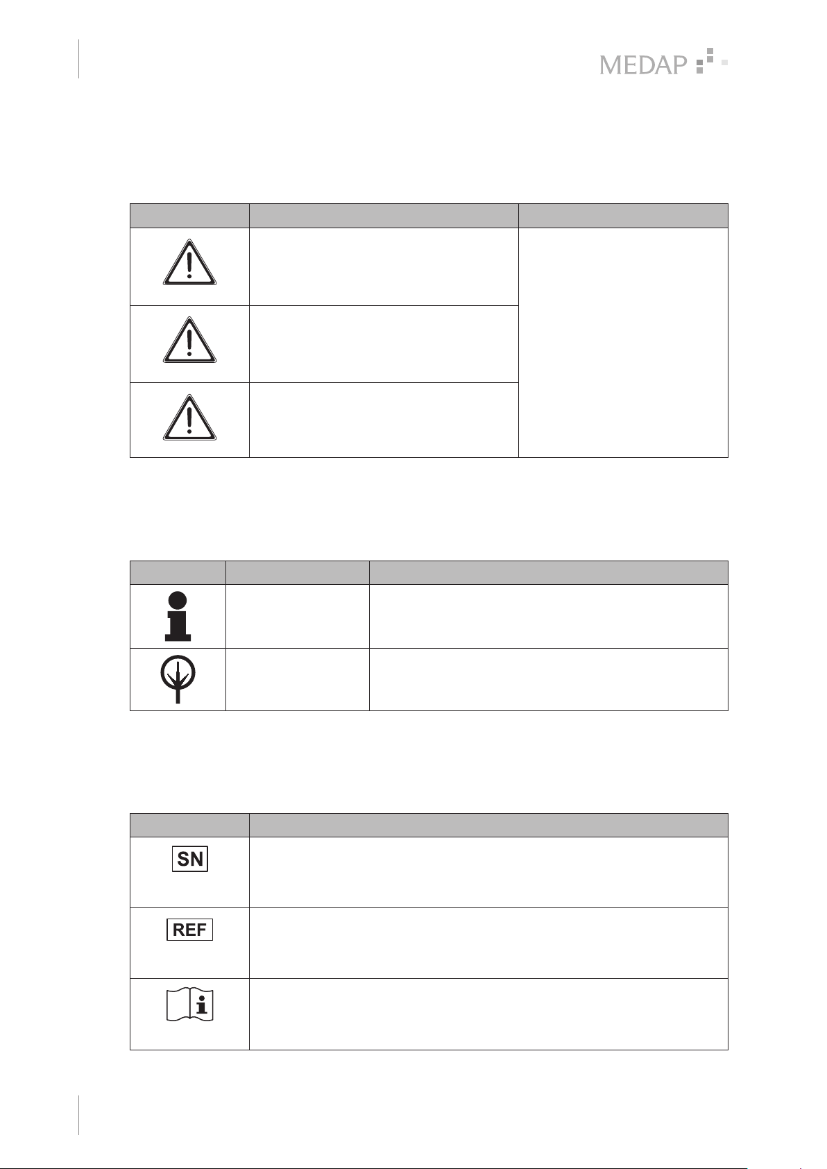
1.2.3.1 Design of safety notes
Pictogram Descriptor Text
DANGER!
Indicates a direct and immediate risk to
persons which may be fatal or result in
most serious injury.
WARNING!
Indicates a potential risk to persons or
property which may result in health hazard
or grave property damage.
CAUTION!
Indicates a potential risk to property which
may result in property damage.
The text for the safety note
describes the type of risk and
how to avert it.
Tab. 1: Design of safety notes
1.2.3.2 Structure of notes
Notes not referring to personal injury or property damage are structured as follows:
Pictogram Descriptor Reference to
NOTE Supplementary assistance or further useful information
ENVIRONMENT Information regarding proper disposal.
Tab. 2: Structure of notes
1.2.4 Symbols used
Symbols are attached to products, type plates and packaging.
Symbols Identification
without potential injury to persons or property damage is
described in the text of the note.
Labelling in compliance with the ISO 15223-1 standard.
Symbol for ‘Serial number’.
6
GA 5752 5555 GB 05
Labelling in compliance with the ISO 15223-1 standard.
Symbol for ‘Product number’.
Labelling in compliance with the ISO 15223-1 standard.
Symbol for ‘Follow operating instructions’.
Page 7
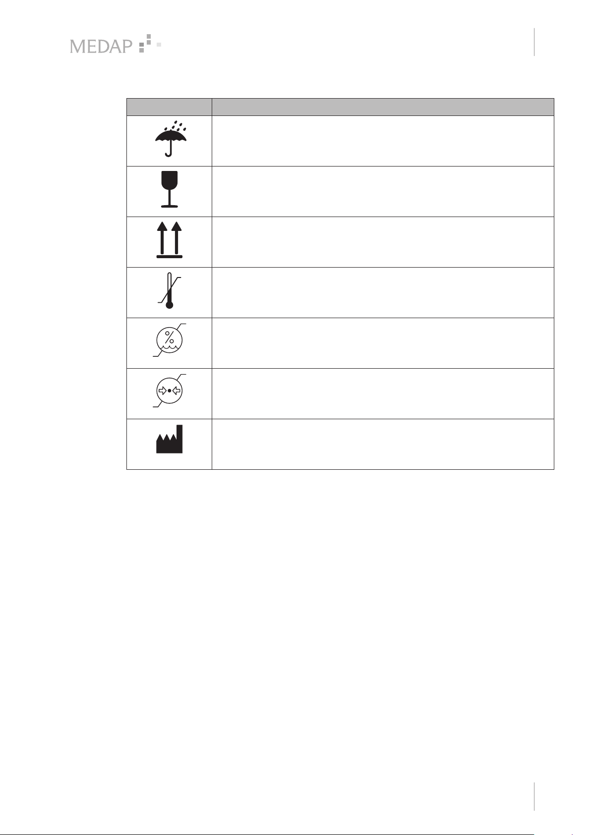
Symbols Identification
Packaging label.
Symbol for ‘Keep dry’.
Packaging label.
Symbol for ‘Fragile! Handle with care’.
Packaging label.
Symbol for ‘Top’.
Labelling in compliance with the ISO 15223-1 standard.
Symbol for ‘Temperature limitations’.
Introduction
Disposal
1
Tab. 3: Symbols
1.3 Disposal
1.3.1 Packaging
The packaging is made of materials compatible with the environment. ATMOS will dispose of the
packaging materials upon request.
1.3.2 ATMOS products
ATMOS will take back used products or those which are no longer in service.
Please contact your ATMOS representative for more detailed information.
Labelling in compliance with the ISO 15223-1 standard.
Symbol for ‘Relative humidity’.
Labelling in compliance with the ISO 15223-1 standard.
Symbol for ‘Atmospheric pressure’.
Labelling in compliance with the ISO 15223-1 standard.
Symbol for ‘Name and address of the manufacturer as well as date of
manufacture’.
GA 5752 5555 GB 05
7
Page 8
Introduction
1
2
4
3
5
6
1
Overview of Oxyrator (REF 5752 5548)
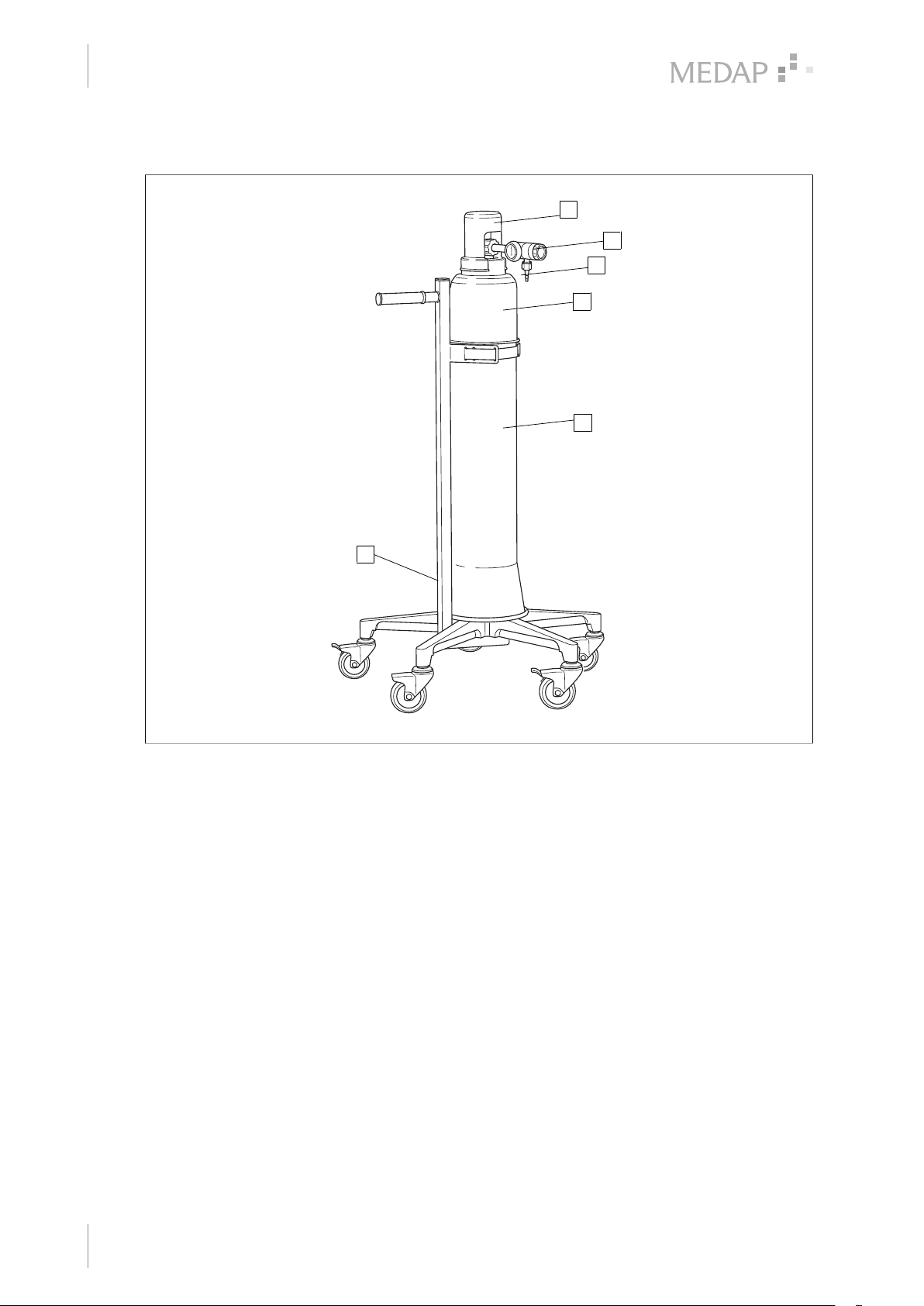
1.4 Overview of Oxyrator (REF 5752 5548)
1
2
3
4
5
6
Fig. 1: Overview of Oxyrator
1 Valve cap 4 Cylinder cover
2 Pressure regulator 5 Cylinder jacket
3 Tube adapter 6 Cylinder trolley
8
GA 5752 5555 GB 05
Page 9
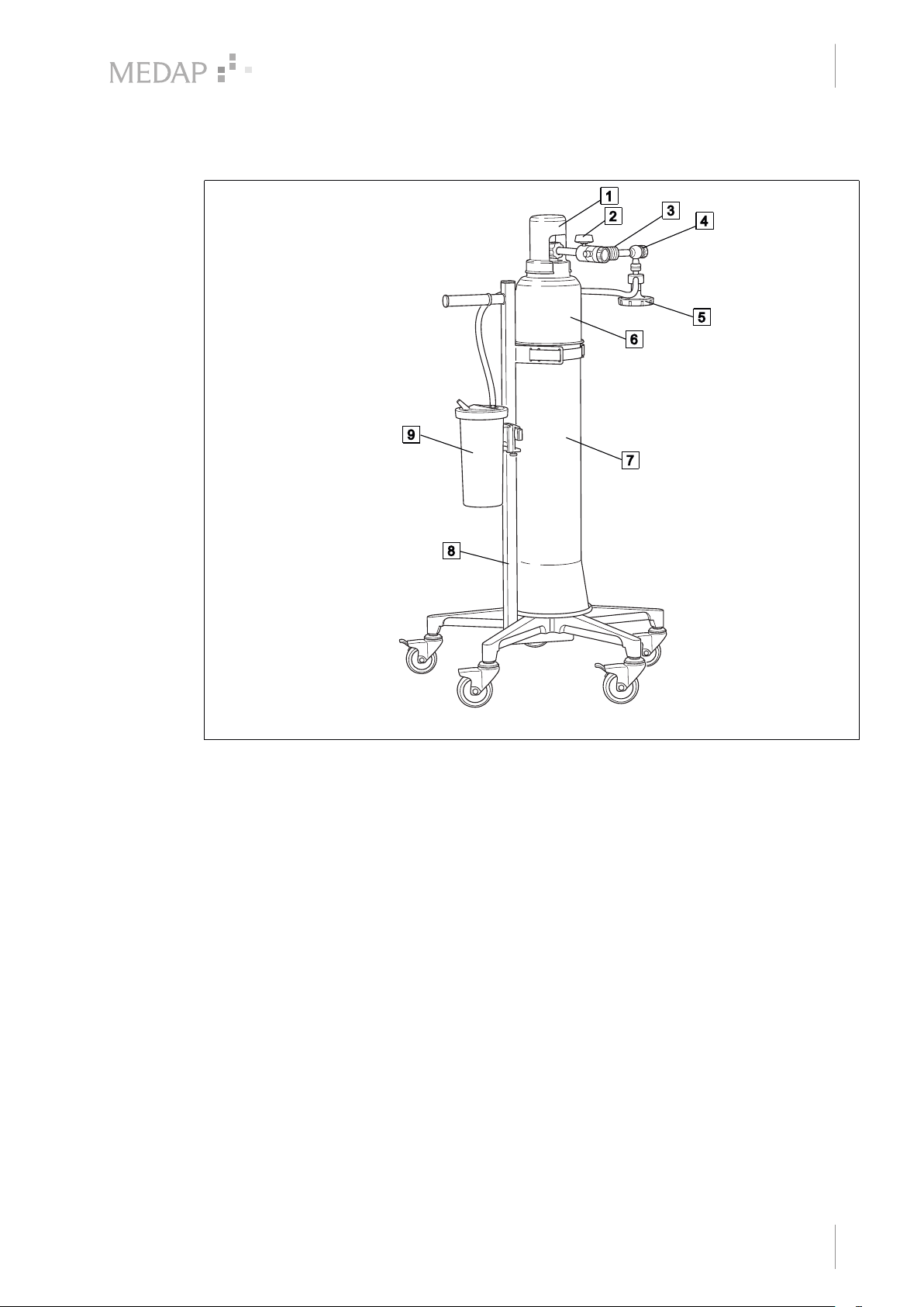
Overview of Oxyrator with aspirator (REF 5752 5549)
1.5 Overview of Oxyrator with aspirator (REF 5752 5549)
Introduction
1
Fig. 2: Overview of Oxyrator with aspirator
1 Valve cap 5 Gas-jet pump
2 Gauge of pressure regulator 6 Cylinder cover
3 Pressure regulator 7 Cylinder jacket
4 Fine regulator 8 Cylinder trolley
1.6 Basic requirements
1.6.1 Use in accordance with the intended purpose
This product is a medical device according to the Medical Devices Directive 93/42/EEC.
This product is to be used exclusively in human medicine.
Patients may be placed on the device and put in position only under the supervision of medical
personnel.
Accessories
Accessories or combinations of accessories may be utilised only as and when indicated in these
operating instructions.
Use other accessories, combinations and parts subject to wear only if these are intended
expressly for the application and will not adversely affect performance features or safety
requirements.
9 Aspiration set
GA 5752 5555 GB 05
9
Page 10

Introduction
1
Basic requirements
1.6.2 Applicable standards
The product satisfies the basic requirements set forth in Annex I to Council Directive 93/42/EEC
concerning medical devices (Medical Devices Directive) as well as the applicable national
(German) codes and the Medical Devices Act (MPG) in Germany. This has also been
demonstrated through the application of the corresponding standards which have been
harmonised with Directive 93/42/EEC.
1.6.3 Treatment system as per Article 12
The product consists of several components which together comprise one treatment system as
per Article 12 of the Medical Devices Directive 93/42/EEC (Paragraph 10 of the Medical Devices
Act).
The Oxyrator consists of the following components:
• O2 pressure regulator with flowmeter (REF 5752 5543)
• Cylinder trolley for 10 or 11 litre oxygen cylinders (REF 5752 4675)
• Cylinder jacket for 10 or 11 litre oxygen cylinders, complete with valve cap and cylinder cover
(REF 5752 4676).
The Oxyrator with aspirator consists of the following components:
• Pressure regulator with flowmeter and additional DIN coupling (REF 5752 5544)
• Cylinder trolley for 10 or 11 litre oxygen cylinders (REF 5752 4675)
• Cylinder jacket for 10 or 11 litre oxygen cylinders, complete with valve cap and cylinder cover
(REF 5752 4676).
• 20 cm equipment rail with holder for cylinder trolley (REF 5752 4677)
• FINA fine regulator O2 (REF 5752 3705)
• Gas-jet pump O2 LF/HV (REF 5750 7540)
• Application set aspiration (REF 5752 4681)
All Oxyrator and Oxyrator with aspirator components may be reused after disinfection. Combined
use with the Oxyrator is restricted exclusively to equipment or parts which have been approved
by ATMOS for such use. The intended purposes and operating instructions of the application
parts must be observed.
1.6.4 Intended purpose
Name: Oxyrator
Main function: Treatment system consisting of several components for
Medical indications /
application:
10
GA 5752 5555 GB 05
Oxyrator with aspirator
administration of oxygen, in addition, the Oxyrator with aspirator is
suitable for bronchial aspiration
Supply of patients with medical oxygen if a central gas supply is not
available (e.g. interhospital transport). The Oxyrator with aspirator
also allows for the conversion of the oxygen into vacuum using the
Venturi principle for bronchial aspiration.
Page 11

Introduction
Basic requirements
1
Specification of the main
function:
User profile: Doctor, medically trained staff
Patient groups: Patients of all ages
Application organ: Outlet flowmeter: Lung
The Oxyrator and the Oxyrator with aspirator are treatment systems
as per Article 12 of the Medical Devices Directive 93/42/EEC
(Paragraph 10 of the Medical Devices Act).
The components are listed in the following chapter of this operating
instructions.
The cylinder trolley provides a basis for a 10 or 11 l oxygen
cylinder. A pressure reducer is connected to the oxygen cylinder
and reduces the pressure to the usual pressure of central gas
supply systems. An integrated flowmeter in the pressure reducer
can be used for inhalation or insufflation of oxygen within the scope
of oxygen enrichment for patients breathing by themselves. For the
Oxyrator with aspirator the pressure reducer has an additional
coupling DIN. In the coupling DIN a fine regulator oxygen can be
inserted. A gas-jet pump can be connected to the outlet of the fine
regulator, converting the oxygen into vacuum via the Venturi
principle. The application set aspiration consists of a septic fluid jar
with lid for bronchial aspiration. The permissible pressure in the
oxygen cylinder is 200 bar.
Outlet coupling: No specific organ
Application time: For continuous operation; in practice, short-term use on the patient
(< 30 days)
Application site: The application site is the clinical environment and doctor’s
practices. The application of the product may only be performed by
medically trained and instructed staff.
Contraindications: The Oxyrator and Oxyrator with aspirator may not be used for the
following purposes:
• Outside the medical sector
• In MR areas
• For ultra-pure gases
• For corrosive, aggressive and toxic gases, acetylene, propane,
butane and other flammable gases
• With a supply pressure higher than 200 bar
• The undosed supply of medical oxygen (connection of tapping
units intended for this purpose is strictly necessary)
• When applying oxygen in its function as a medication, it is absolutely necessary to measure the flow rate
The product is: Active
Sterility: Not a sterile product
Single-use product /
reprocessing:
The treatment system and parts of the accessories are reusable.
For information on reprocessing, cleaning and disinfection please
see the operating instructions
GA 5752 5555 GB 05
11
Page 12

Introduction
1
Basic requirements
1.6.5 Interface description of Oxyrator
1.6.5.1 Oxygen cylinder
The oxygen cylinder is mounted to the carrying board with a clamp bracket and supplies oxygen
to the emergency oxygen unit.
Technical specifications
• 10 or 11 l
• Cylinder diameter 140 mm
• Cylinder height approximately 1000 mm
• Weight maximum 16 kg
• 200 bar / 20000 kPa
• Connection DIN 477-1
1.6.5.2 Connection tube
The connection tube is used to connect the tube adapter on the flowmeter outlet of the pressure
regulator to the inhalation mask.
Technical specifications
• Inner diameter 5 mm
Prerequisites
• The inner diameter of the connection tube should match the tube connector on the flowmeter
outlet of the pressure regulator and the tube connector of the inhalation mask.
1.6.5.3 Bubble humidifier (REF 5752 5315)
The bubble humidifier can be integrated between the flowmeter outlet of the pressure regulator
and the connection tube of the inhalation mask to humidify the oxygen. The bubble humidifier is
connected to the flowmeter outlet of the pressure regulator. The connection tube to the inhalation
mask is connected at the outlet of the bubble humidifier [ Page 17].
1.6.6 Interface description of Oxyrator with aspirator
1.6.6.1 Oxygen cylinder
The oxygen cylinder is mounted to the carrying board with a clamp bracket and supplies oxygen
to the emergency oxygen unit.
Technical specifications
• 10 or 11 l
• Cylinder diameter 140 mm
• Cylinder height approximately 1000 mm
• Weight maximum 16 kg
• 200 bar / 20000 kPa
• Connection DIN 477-1
1.6.6.2 Vacuum connection tube
The vacuum connection tube is used to connect the tapping unit and the septic fluid jar.
12
GA 5752 5555 GB 05
Page 13

Technical specifications
• Shore hardness of 60
• Inner diameter 6 mm
• Length 50 cm (±10 cm)
• Vacuum resistant down to −95 kPa (may not collapse)
Prerequisites
• The inner diameter of the vacuum connection tube should match the outer diameter of the
tube connector on the septic fluid jar cap of the pump.
The vacuum connection tube will be referred to only as ‘connection tube’ below.
1.6.6.3 Suction tube
The suction tube is used to connect the tube connector on the septic fluid jar on the patient side
and the fingertip or the utensil.
Technical specifications
• Shore hardness of 60
• Inner diameter 6 - 8 mm
• Length 1.3 m to 3.0 m
• Vacuum resistant down to −95 kPa (may not collapse)
Introduction
Basic requirements
1
Prerequisites
• The outer diameter of the tube connector on the patient side of the septic fluid jar cap must
match the inner diameter of the suction tube.
1.6.6.4 Connection tube
The connection tube is used to connect the tube adapter on the flowmeter outlet of the pressure
regulator to the inhalation mask.
Technical specifications
• Inner diameter 5 mm
Prerequisites
• The inner diameter of the connection tube should match the tube connector on the flowmeter
outlet of the pressure regulator and the tube connector of the inhalation mask.
1.6.6.5 Bubble humidifier (REF 5752 5315)
The bubble humidifier can be integrated between the flowmeter outlet of the pressure regulator
and the connection tube of the inhalation mask to humidify the oxygen. Instead of the tube
adapter, the angled adapter (REF 5752 5606) is connected to the flowmeter outlet of the
pressure regulator for this purpose. The bubble humidifier is connected at the outlet of the angled
adapter, and the connection tube to the inhalation mask is connected at the outlet of the bubble
humidifier [ page 21].
GA 5752 5555 GB 05
13
Page 14
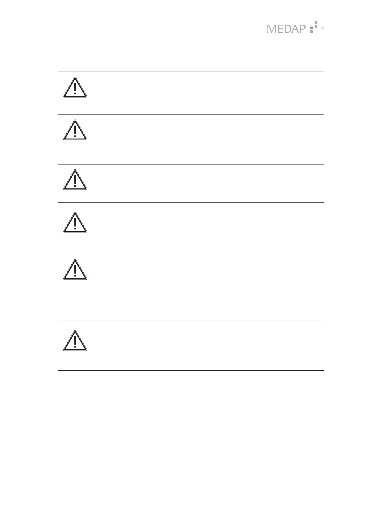
Safety notes
2
Basic requirements
2 Safety notes
DANGER!
Danger to life!
The undosed supply of gases is hazardous to the patient.
Use only tapping units with dosing systems.
WARNING!
Risk of injury!
Hazard resulting from incorrect handling.
Be absolutely sure to observe the operating instructions for all the products used in
the configuration.
WARNING!
Risk of injury!
Worn or damaged products or accessories can cause injuries.
Use only products and accessories which are in perfect condition.
CAUTION!
Observe ambient conditions!
The precision, operation, mechanical stability and tightness of the product cannot
be guaranteed if the maximum upper and lower ambient temperatures are
exceeded.
DANGER!
Danger to life!
Danger due to improper configuration of the system.
The configuration of the overall system as well as the functional testing are subject
to the overall responsibility of the medical staff. The operator must check the proper
functionality and suitability of the connected accessories for each intended
application prior to every use, in particular, connection parts, sealing properties and
suitability with regard to material, work pressure and flow.
CAUTION!
Property damage!
Danger of tipping if position is unstable!
Place the product on a firm, level surface. Operation is only permitted when the
castors are in a locked position.
14
GA 5752 5555 GB 05
Page 15
3 Initial operation
1
3.1 General
WARNING!
Infection hazard!
Contaminated components may endanger the health of staff and patients.
Ensure the product is prepared as per hygiene standards before using it for the first
time.
NOTE
Refer to the operating instructions of the cylinder trolley (REF 5752 4732) for
information on how to assemble the cylinder trolley and the cylinder jacket.
NOTE
The oxygen cylinder is not included in the scope of delivery.
Initial operation
General
3
The scope of delivery includes the operating instructions as well as the ordered product version
Oxyrator (REF 5752 5548) or Oxyrator with aspirator (REF 5752 5549) in line with the respective
individual components.
Remove the product from its packaging and check the shipment for completeness and to ensure
the scope of delivery is intact.
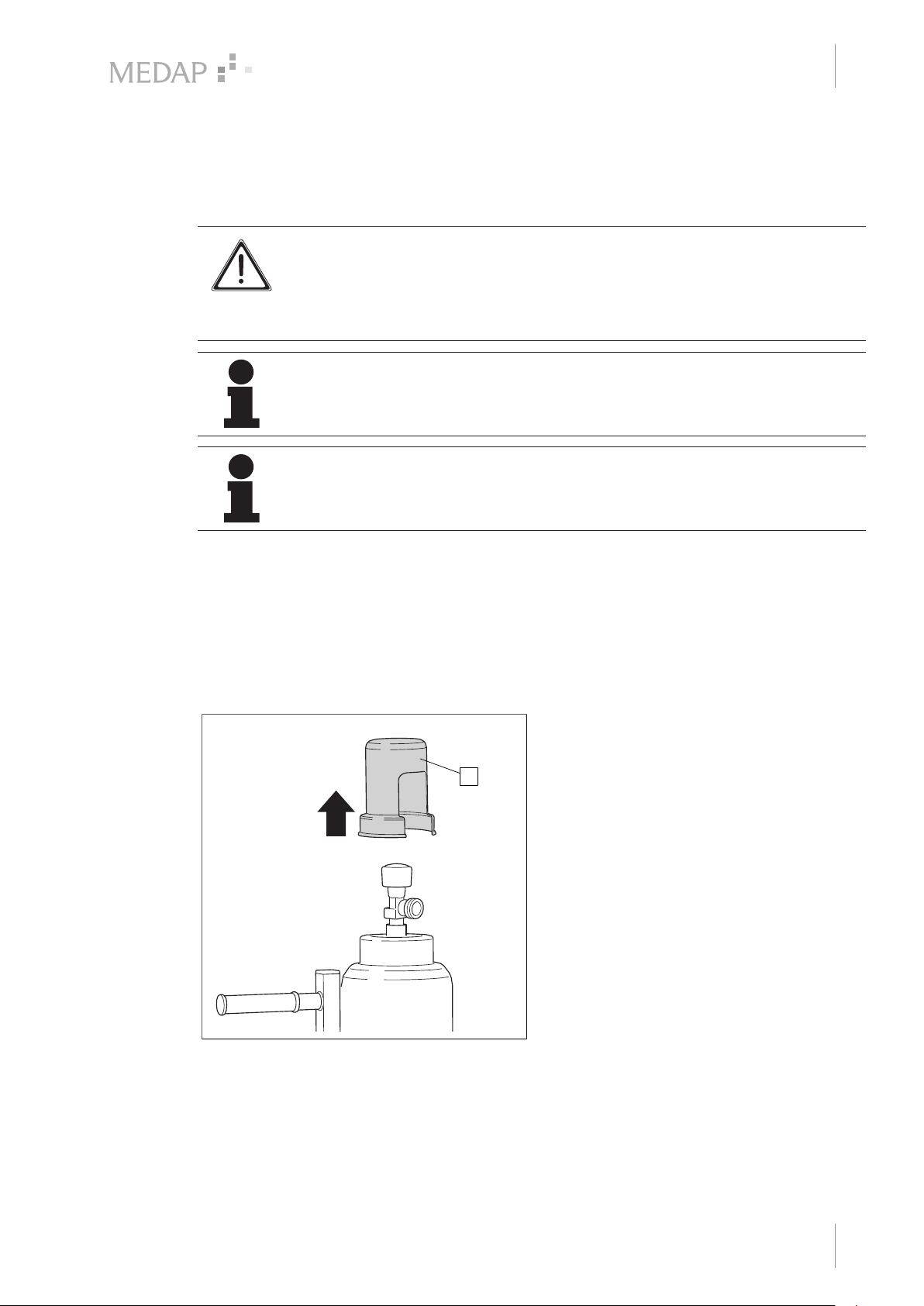
3.2 Connecting the pressure regulator
Mounting is described using the pressure regulator (REF 5752 5543) as an example.
Remove the valve cap (1).
1
Fig. 3: Removing the valve cap
GA 5752 5555 GB 05
15
Page 16
3
2
1
1
2
Initial operation
Oxyrator (REF 5752 5548)
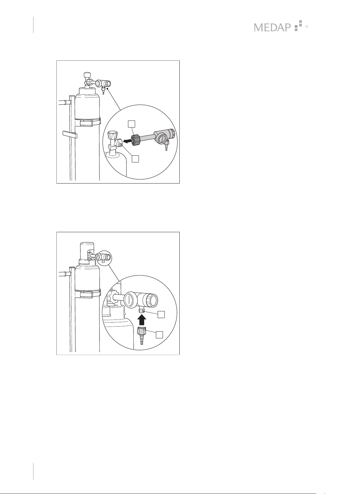
Connecting the pressure regulator
Ensure that the pressure regulator is
closed.
Plug the cap nut (1) of the pressure
regulator onto the thread of the connection
valve (2) of the oxygen cylinder.
Tighten the cap nut by hand.
1
2
The pressure regulator is mounted.
Fig. 4: Connecting the pressure regulator
3.3 Oxyrator (REF 5752 5548)
3.3.1 Oxygen supply via tube adapter
Screwing on the tube adapter
Screw the tube adapter (1) onto the tube
connector (2) of the pressure regulator.
2
1
16
Fig. 5: Screwing on the tube adapter
GA 5752 5555 GB 05
Page 17
Initial operation
1
2
1
2
3
4
5
Oxyrator (REF 5752 5548)
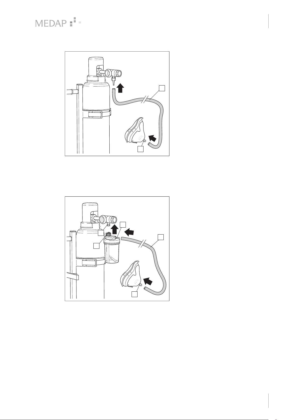
Connecting the connection tube
Attach the connection tube (1) to the tube
adapter.
Attach the other end of the connection tube
to the inhalation mask (2).
1
2
Oxygen supply is functional.
3
Fig. 6: Connecting the connection tube
3.3.2 Connecting accessories (optional)
3.3.2.1 Connection of bubble humidifier (REF 5752 5315)
Connecting the bubble humidifier
4
2
3
1
5
Ensure that the tube connector of the
bubble humidifier has two seals.
Screw the bubble humidifier (1) directly to
the flowmeter outlet (2) and tighten fingertight as far as it will go.
Attach the connection tube (3) to the tube
connector (4) of the bubble humidifier.
Attach the other end of the connection tube
to the inhalation mask (5).
Oxygen supply is functional.
Pay attention that no tensile forces affect
the bubble humidifier.
Fig. 7: Connection of bubble humidifier
3.3.2.2 Connection of disposable humidifiers from other manufacturers
Disposable humidifiers may be connected to the flowmeter outlet. An angled adapter must be
used for disposable humidifiers.
Screw the disposable humidifier directly to the flowmeter outlet (2) and tighten finger-tight as
far as it will go.
GA 5752 5555 GB 05
17
Page 18
Initial operation
1
2
3
Oxyrator with aspirator (REF 5752 5549)
3.4 Oxyrator with aspirator (REF 5752 5549)
NOTE
Oxygen supply via tube adapter [ Page 16] or connecting accessories.
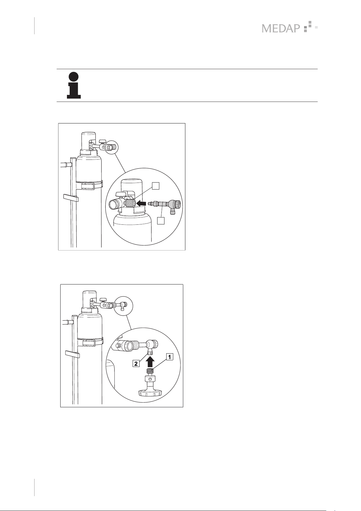
3.4.1 Connecting the fine regulator
2
Connecting the fine regulator
Insert the fine regulator (1) into the DIN
coupling (2) on the pressure regulator.
Fig. 8: Connecting the fine regulator
3.4.2 Connecting the gas-jet pump
1
Connecting the gas-jet pump
Fit the cap nut (1) of the gas-jet pump onto
the connection thread (2) of the fine
regulator.
Tighten the cap nut.
The gas-jet pump is mounted.
18
Fig. 9: Connecting the gas-jet pump
GA 5752 5555 GB 05
Page 19
3.4.3 Mounting the tubes
NOTE
Use the hydrophobic bacterial and viral filter (REF 5752 2557) instead of the tube
adapter (REF 5752 2295) to increase safety.
Initial operation
Oxyrator with aspirator (REF 5752 5549)
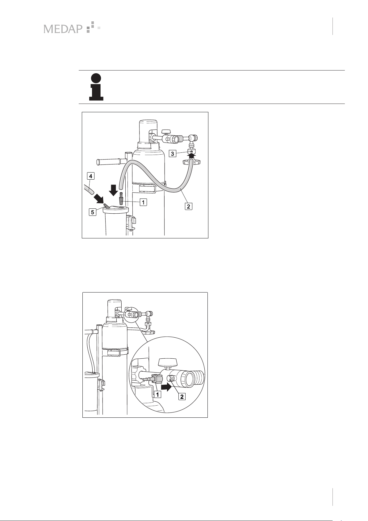
Mounting the tubes
Fit the adapter (1) into the septic fluid jar
cap.
Attach the connection tube (2) to the
adapter.
Attach the other end of the connection tube
to the tube connector (3) on the gas-jet
pump.
Attach the suction tube (4) to the patient-
side tube connector (5) on the septic fluid
jar cap.
Aspiration set is functional.
3
Fig. 10: Mounting the tubes
3.4.4 Aspiration and oxygen therapy
3.4.4.1 Oxygen supply via tube adapter
Screwing on the tube adapter
Screw the tube adapter (1) onto the tube
connector (2) of the pressure regulator.
Fig. 11: Screwing on the tube adapter
GA 5752 5555 GB 05
19
Page 20
3
Initial operation
Oxyrator with aspirator (REF 5752 5549)
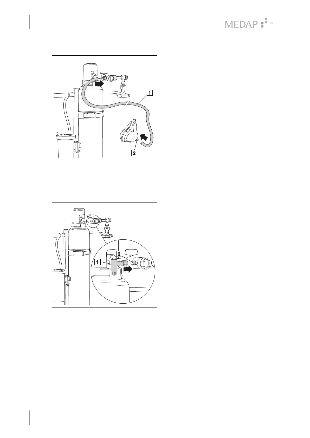
Connecting the connection tube
Attach the connection tube (1) to the tube
adapter.
Attach the other end of the connection tube
to the inhalation mask (2).
Oxygen supply is functional.
Fig. 12: Connecting the connection tube
3.4.4.2 Connecting accessories (optional)
Connection of bubble humidifier (REF 5752 5315)
Fig. 13: Connecting the angled adapter / adapter
for humidifier
Connection of angled adapter (REF 5752
5606) (optional)
Ensure that the adapter for humidifier
contains a flat gasket.
Screw the angled adapter (1) onto the tube
connector (2) of the pressure regulator.
20
GA 5752 5555 GB 05
Page 21
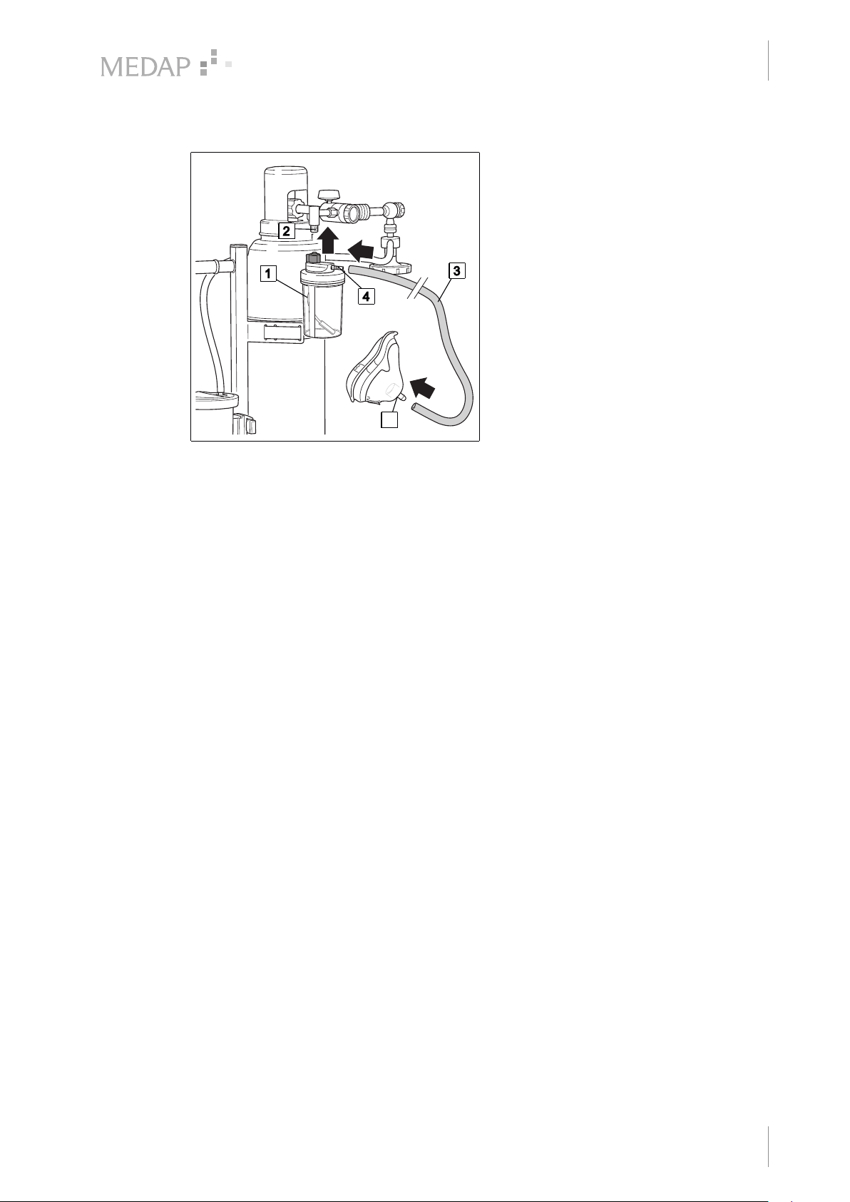
Initial operation
Oxyrator with aspirator (REF 5752 5549)
Connecting the bubble humidifier
Ensure that the tube connector of the
bubble humidifier has two seals.
Screw the bubble humidifier (1) directly to
the angled adapter (2) and tighten fingertight as far as it will go.
Attach the connection tube (3) to the tube
connector (4) of the bubble humidifier.
Attach the other end of the connection tube
to the inhalation mask (5).
Oxygen supply is functional.
Pay attention that no tensile forces affect
the bubble humidifier.
5
3
Fig. 14: Connecting the bubble humidifier
Connection of disposable humidifiers from other manufacturers
Disposable humidifiers may be connected to the flowmeter outlet. An angled adapter must be
used for disposable humidifiers.
Screw the disposable humidifier directly to the flowmeter outlet (2) and tighten finger-tight as
far as it will go.
GA 5752 5555 GB 05
21
Page 22
Operation
4
Function test
4 Operation
4.1 Function test
Prior to using the system, the operator must check that the product is fully functional and in good
condition. Prior to each use, carry out the following functionality checks:
Pressure regulator
• State of manual tightening
• State of seal in cap nut
• Ease of movement at the connector threads (difficulty of movement is an indication of damage
or soiling to the threads)
• Damage to supply tubes
• Airtightness
• Intact connection thread for accessories
NOTE
Unscrew manual tightening only after pressure has been fully released from the
pressure regulator. First, close the valve on the oxygen cylinder; then release the
pressure on the click-stop flowmeter.
Aspirator unit (only for Oxyrator with aspirator)
• Damage of seal rims of float in the overflow protection device
• Any cracks in septic fluid jar
• Splintering at the contact surfaces of the septic fluid jar
• Damage to seal of the septic fluid jar cap
• Cracked or hardened connection tubes
• State of seal in cap nut of gas-jet pump
• Free movement of fine regulator for gas-jet pump
Oxygen cylinder
• Sufficient filling level
4.2 Check the filling level of the oxygen cylinder
NOTE
Check airtightness of all accessory connections before beginning treatment.
Manually retighten connecting nuts as necessary and readjust to the amount of
oxygen required.
The duration of use in treatment depends on the filling level of the oxygen cylinder. The filling
level may be checked as follows:
Cylinder pressure (kPa) * cylinder volume (V) / O2 dosage (l/min)
Example of calculation:
• Cylinder pressure = 200 kPa
• Cylinder volume = 10 l
• O2 dosage = 4 (l/min)
• 200 X 10 / 4 = 500 min
The cylinder contents will last for approximately 8 hours.
22
Checking the filling level
Open the cylinder valve.
GA 5752 5555 GB 05
Page 23
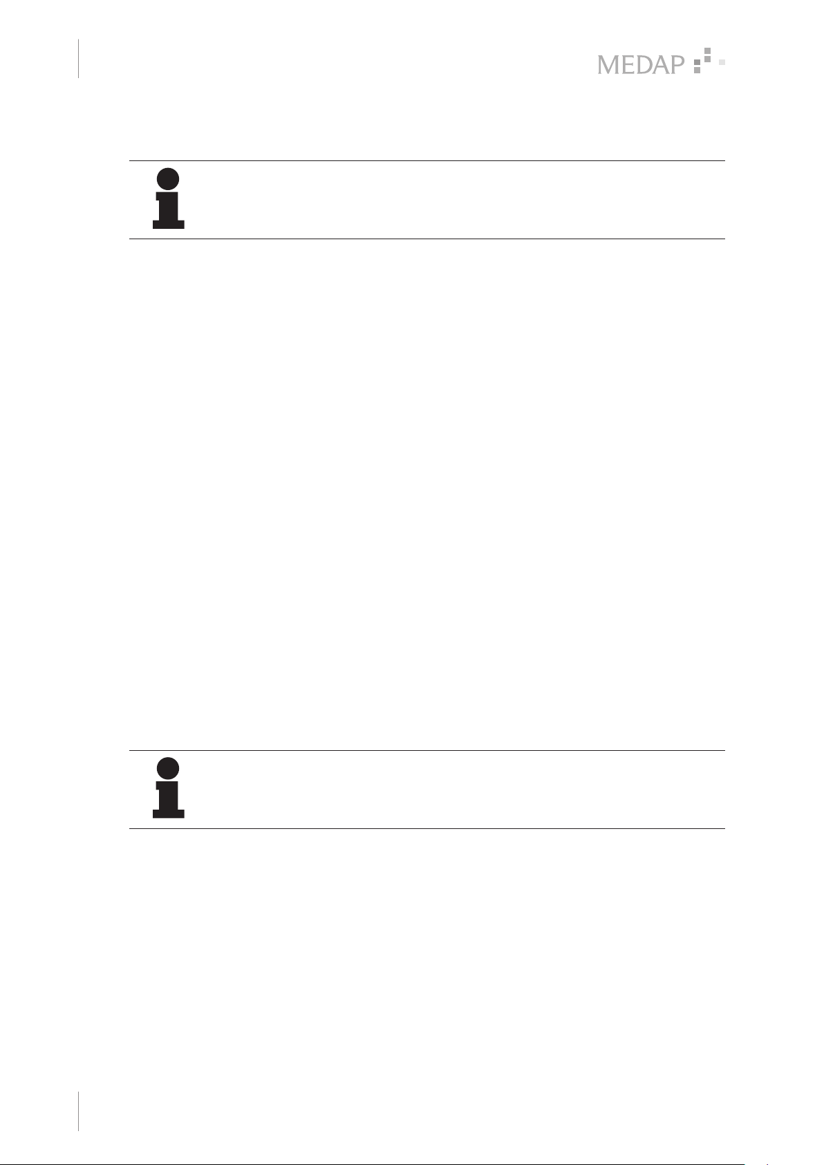
Set the hand wheel of the click-stop flowmeter at the pressure regulator.
3
2
1
Check the gauge to see whether the cylinder contains sufficient oxygen for treatment.
4.3 Oxygen extraction
Operation
Oxygen extraction
Setting the flow
Remove the valve cap.
Set the hand wheel (1) of the click-stop
flowmeter to zero (2).
Open the cylinder valve of the oxygen
cylinder and check whether the cylinder
3
contains sufficient content for treatment [
Page 22].
Set the desired flow quantity on the hand
wheel.
The arrow (3) on the pressure regulator
indicates flow quantity.
4
2
Fig. 15: Setting the flow
4.4 Setting the vacuum level (only for Oxyrator with aspirator)
NOTE
Check airtightness of all accessory connections before beginning treatment.
Manually retighten connecting nuts as necessary and readjust to the amount of
oxygen required.
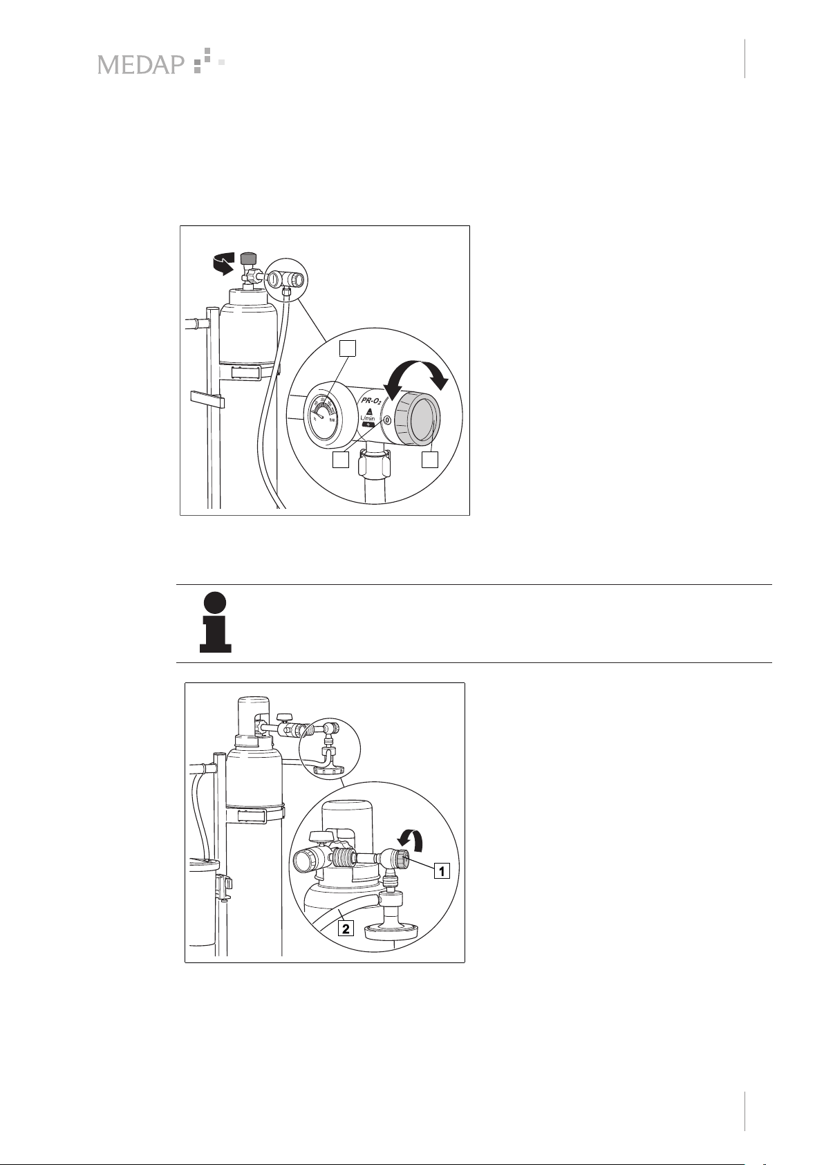
1
Setting the vacuum level
Close the control valve (1) on the fine
regulator.
Open the cylinder valve of the oxygen
cylinder and check whether the cylinder
contains sufficient content for treatment [
Page 22].
Turn the control valve of the fine regulator
slowly one full rotation in an anticlockwise
direction.
Bend the suction tube (2).
Set the suction rate required using the
control valve.
Fig. 16: Setting the vacuum level
GA 5752 5555 GB 05
23
Page 24
Taking the unit out of operation
2
1
1
5
Stopping oxygen extraction
5 Taking the unit out of operation
5.1 Stopping oxygen extraction
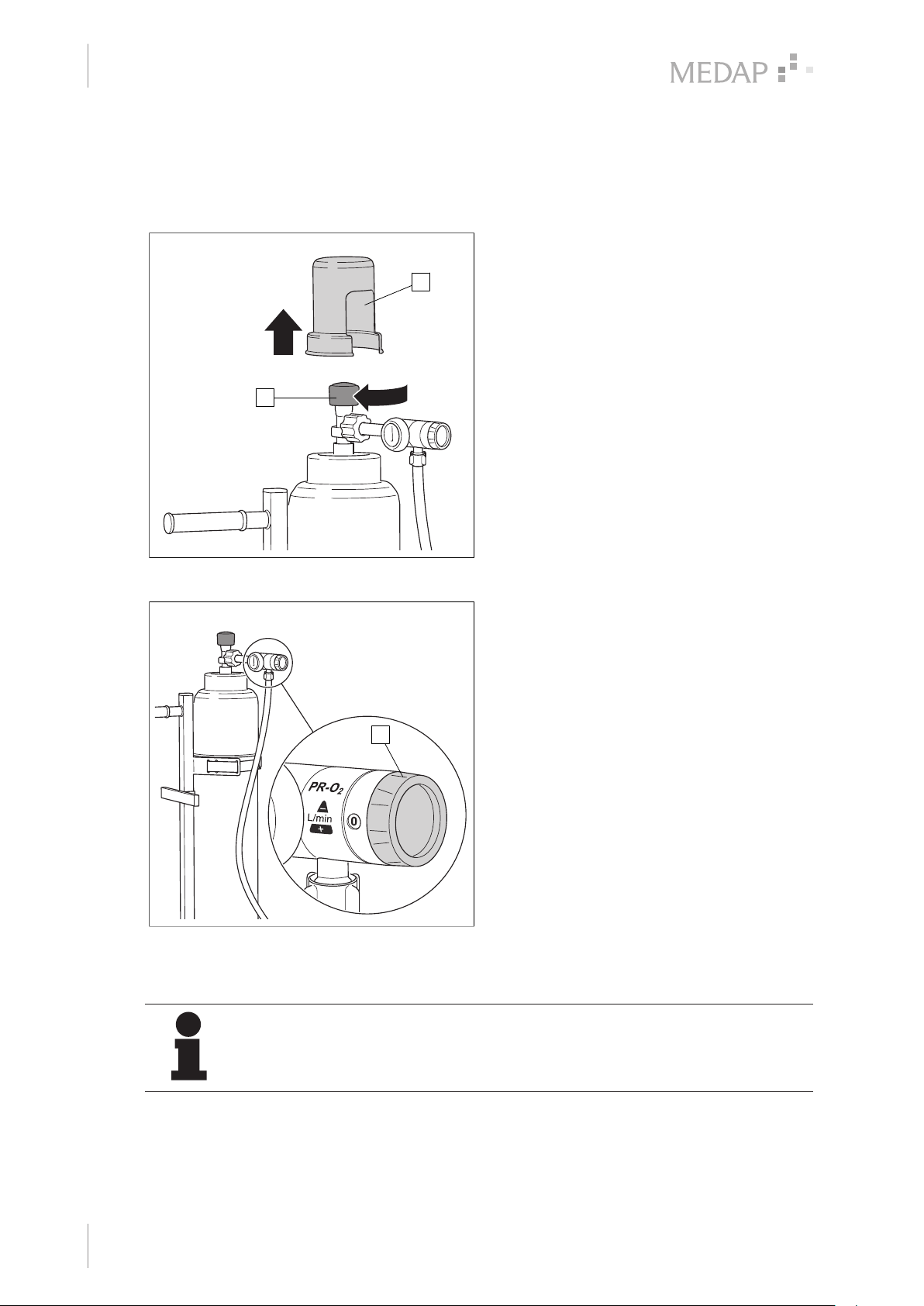
1
2
Closing the cylinder valve
Remove the valve cap (1).
Turn the hand wheel (2) of the cylinder
valve slowly in a clockwise direction.
Cylinder valve is closed.
Oxygen supply is interrupted.
Fig. 17: Closing the cylinder valve
Fig. 18: Closing the pressure regulator
5.2 Replacing the oxygen cylinder
NOTE
Unscrew manual tightening only after pressure has been fully released from the
pressure regulator. First, close the valve on the oxygen cylinder; then release the
pressure on the click-stop flowmeter.
Releasing the pressure
Set the hand wheel (1) of the click-stop
flowmeter to [15].
Pressure is released.
Closing the pressure regulator
1
Set the hand wheel (1) of the click-stop
flowmeter to [0].
24
GA 5752 5555 GB 05
Page 25
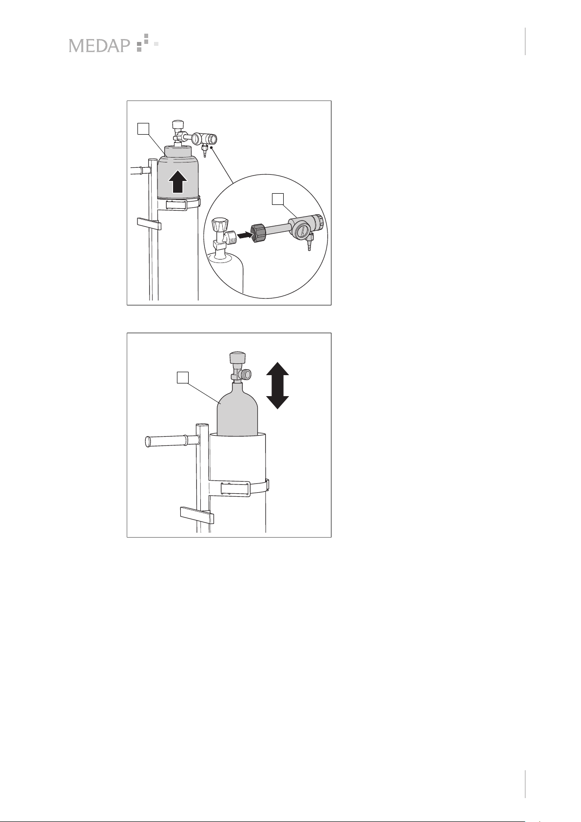
Taking the unit out of operation
2
1
3
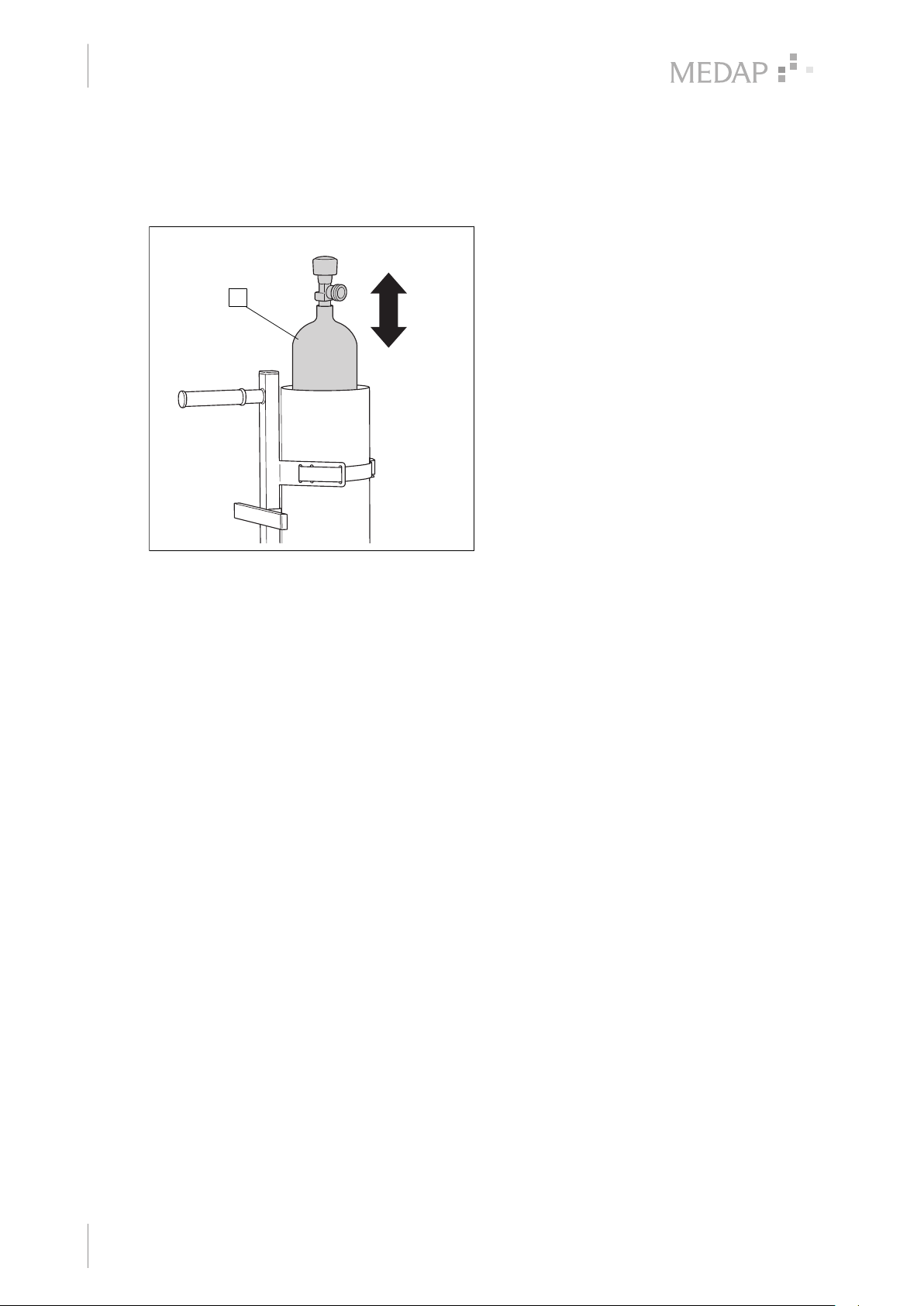
Replacing the oxygen cylinder
Replacing the oxygen cylinder
2
1
Release the pressure.
Close the pressure regulator.
Lock the brakes of the trolley castors.
Unscrew the pressure regulator (1).
Remove the cylinder cover (2).
5
Fig. 19: Replacing the oxygen cylinder
3
Fig. 20: Replacing the oxygen cylinder
Remove the oxygen cylinder (3) from the
cylinder jacket.
Insert a new oxygen cylinder into the
cylinder jacket and connect the pressure
regulator.
Put on the cylinder cover.
Connect the pressure regulator.
GA 5752 5555 GB 05
25
Page 26
Taking the unit out of operation
3
5
Oxyrator with aspirator
5.3 Oxyrator with aspirator
5.3.1 Detaching tubes
3
Detaching tubes
Remove the suction tube (1) from the
patient-side tube connector (5) on the
septic fluid jar cap.
Detach the adapter (2) and connection tube
(3) from the septic fluid jar cap.
Remove the other end of the connection
tube from the connector (4) on the gas-jet
pump.
Fig. 21: Detaching tubes
26
GA 5752 5555 GB 05
Page 27
6 Cleaning and disinfection
6.1 General
The product must be cleaned as well as wipe disinfected after every use. Perform visual and
functional inspections after each cleaning and disinfection process. Please strictly observe the
cleaning instructions in the operating instructions of the connected products.
DANGER!
Risk due to incorrect use of detergents and disinfectants!
It is strictly advised to observe the manufacturer’s instructions regarding how to
use the detergents and disinfectants as well as to observe the valid hospital
hygiene rules.
DANGER!
Infection hazard!
Product may be contaminated.
Always wear gloves for cleaning and disinfection.
Cleaning and disinfection
General
6
GA 5752 5555 GB 05
27
Page 28
Maintenance
7
General
7 Maintenance
7.1 General
Maintenance, repairs and periodic tests may only be carried out by persons who have the
appropriate technical knowledge and are familiar with the product. To carry out these measures,
the person must have the necessary test devices and original spare parts.
ATMOS recommends: Work should be carried out by an authorised ATMOS service partner. This
ensures that repairs and testing are carried out professionally, original spare parts are used and
warranty claims remain unaffected.
WARNING!
Health hazard!
The product is used in the treatment of patients. The product or some of its
components may be contaminated.
Clean and disinfect the product before maintenance and repair.
Repair work may be performed by personnel authorised by ATMOS.
7.2 Periodic tests
Observe the instructions for the individual components.
7.3 Visual and functional inspections
To ensure correct operation, it is necessary to have visual and functional inspections performed
by a trained person prior to each use of the operating table.
Documentation of the results of the visual and functional inspections is recommend and should
include the date and signature of the person who performed the inspections. The following table
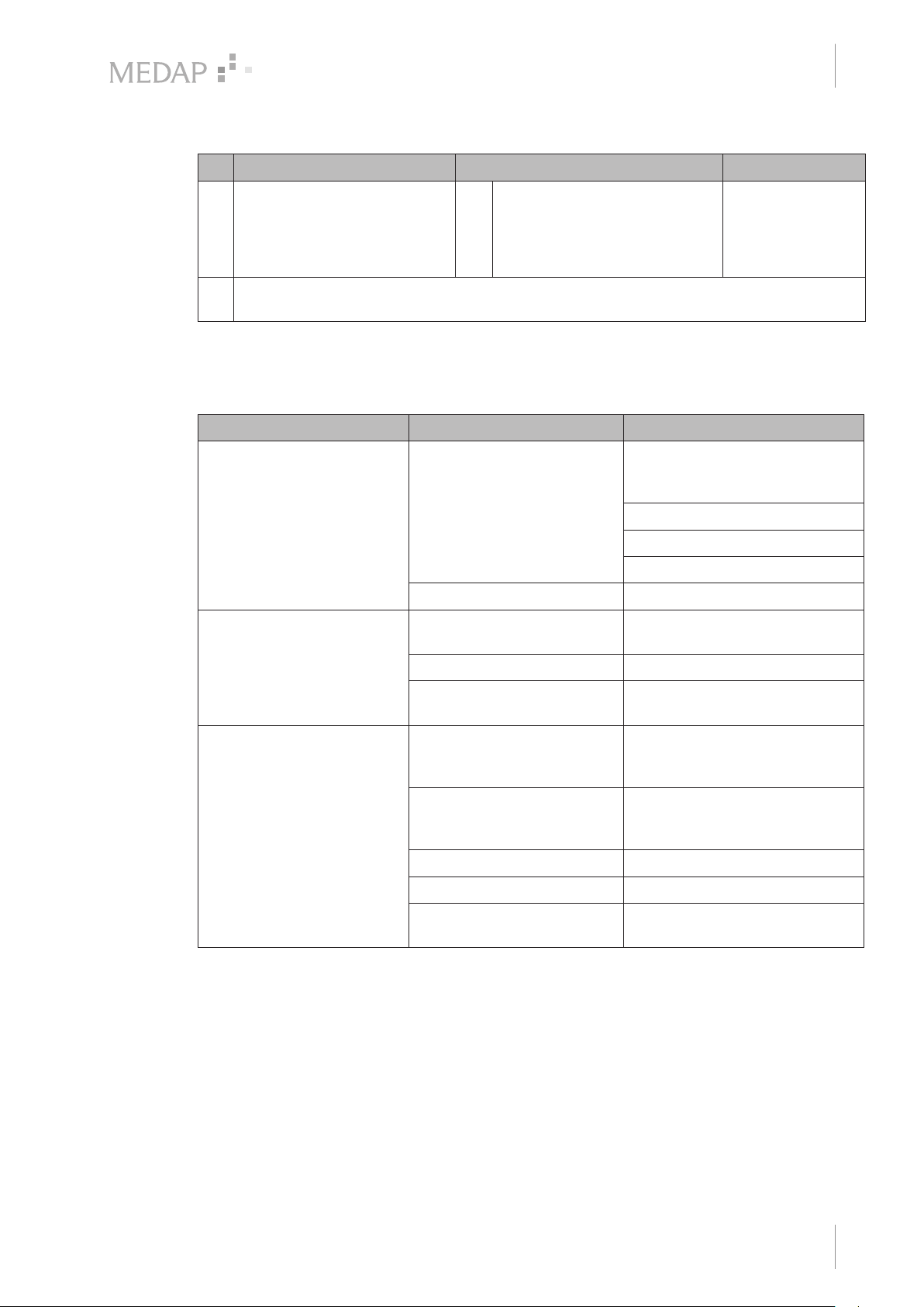
can be used as a template.
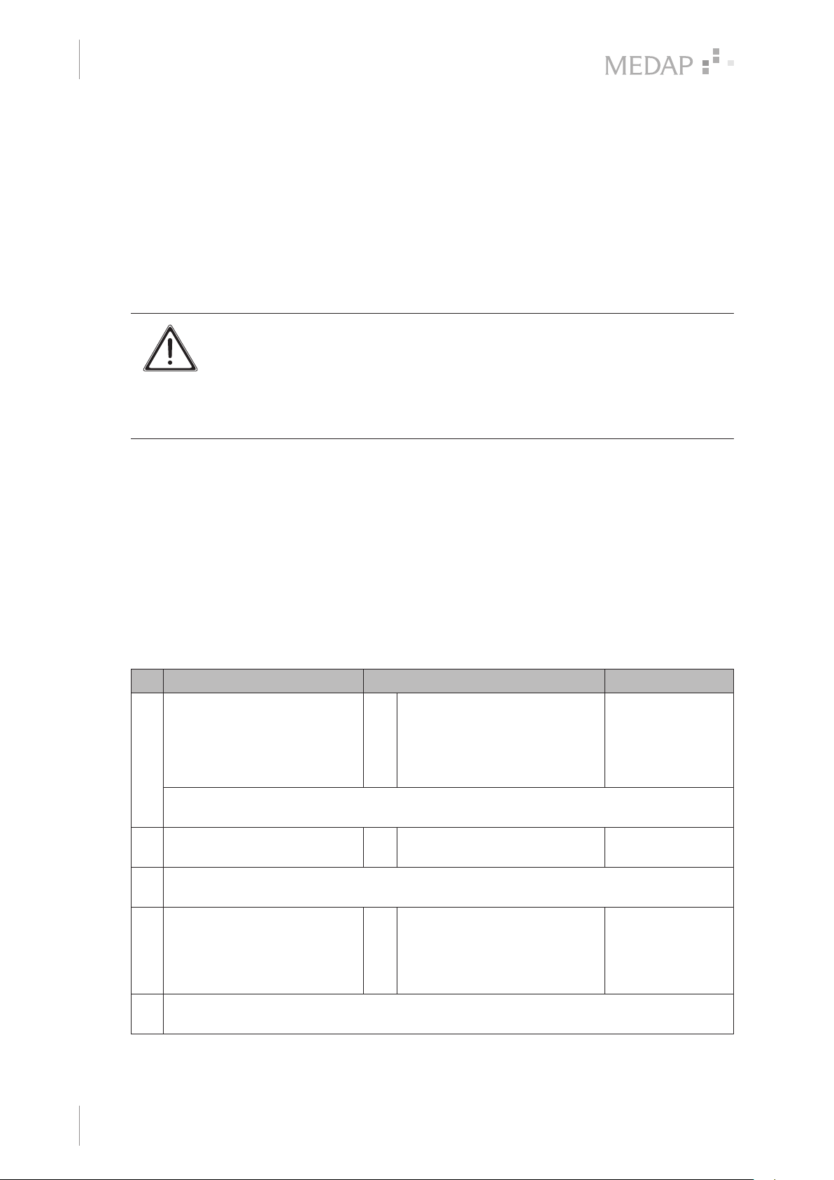
Suggestion:
No. Inspection Defects are present No defects
1 Has the product been cleaned
and disinfected according to
the hygiene guideline?
Comment:
2 Is the product sealed?
Do not use the product any
longer.
Clean and disinfect the
product according to the
guidelines.
Do not use the product any
longer.
28
Comment:
3 Are there damages to
mechanical parts?
Comment:
GA 5752 5555 GB 05
Do not use the product any
longer.
Inform service personnel.
Page 29
Maintenance
Malfunctions and troubleshooting
No. Inspection Defects are present No defects
7
4 (Space for other tests)
Comment:
Tab. 4: Visual and functional inspections
7.4 Malfunctions and troubleshooting
Defect Source of malfunction Troubleshooting
The maximum vacuum level
of −80 kPa cannot be
reached. No or reduced flow
rate.
Cylinder pressure gauge is
not working
No pressure available Check the contents of the oxygen
Gas-jet pump is defective Contact technical service
Oxygen cylinder is empty Replace the oxygen cylinder
cylinder; if necessary, replace the
oxygen cylinder
Fit the fine regulator correctly
Open the oxygen cylinder
Open the fine regulator
No or only little oxygen
released
Tab. 5: Troubleshooting
7.5 Repairs
The following issues may require repairs by the manufacturer or an authorised service partner:
• Liquid has penetrated the device.
• The performance has significantly decreased.
• Inexplicable notifications appear.
• Abnormal noises occur.
• Functional faults cannot be rectified according to the measures in chapter Malfunctions and
troubleshooting [ page 29].
Oxygen cylinder is not open Open the oxygen cylinder
Pressure regulator is
defective
No oxygen pressure Check the contents of the oxygen
Incorrect gauge display Have reducing valve and gauge
Clogged flowmeter Contact technical service
Leaking manual tightening Replace the tapping unit
Leaking or contaminated
accessories
Contact technical service
cylinder; if necessary, replace the
oxygen cylinder
of the gas-jet pump checked; if
necessary, replace tapping unit
Replace or clean accessories
GA 5752 5555 GB 05
29
Page 30

Maintenance
7
Service hotline
If defects are detected, the product may not be used any longer.
Make a note of the deficiencies and the REF number on the data plate and inform your
responsible ATMOS representative.
Observe the information in chapter Foreword [ page 5].
7.6 Service hotline
+49 7653 689-0
7.7 Sending in the device
Remove and properly dispose of consumables.
Clean and disinfect the product and accessories according to the operating instructions.
Place used accessories with the product.
Fill in the form QD 434 ‘Delivery complaint / return shipment’ and the respective
decontamination certificate.
This form is enclosed with each delivery and can be found at www.atmosmed.com.
The device must be well padded and packed in suitable packaging.
Place the form QD 434 ‘Delivery complaint / return shipment’ and the respective
decontamination certificate in an envelope.
Affix the envelope to the outside of the package.
Send the product to ATMOS or to your dealer.
30
GA 5752 5555 GB 05
Page 31
8 Technical specifications
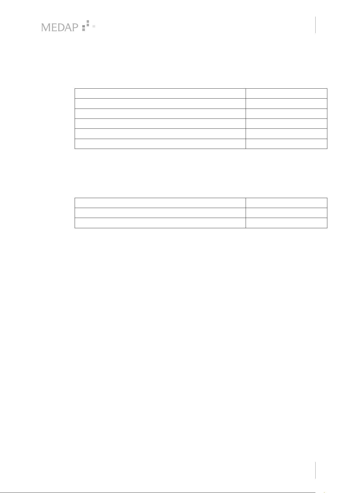
8.1 Ambient conditions
Temperature: Shipping / storage −20 °C to +60 °C
Temperature: Operation −20 °C to +60 °C
Relative humidity: Shipping / storage 10% to 95%
Relative humidity: Operation 10% to 95%
Atmospheric pressure: Shipping / storage 700 hPa to 1060 hPa
Atmospheric pressure: Operation 700 hPa to 1060 hPa
8.2 Technical specifications
Observe the instructions for the individual components in the respective operating instructions.
Technical specifications
Ambient conditions
8
8.3 Dimensions and weights
Dimensions (L x W x H) 610 x 610 x 1170 mm
Weight Oxyrator (without oxygen cylinder) Approximately 11 kg
Weight Oxyrator with aspirator (without oxygen cylinder) Approximately 12 kg
GA 5752 5555 GB 05
31
Page 32

Approved accessories
9
Accessories
9 Approved accessories
The following accessories are not part of the scope of delivery and must be ordered separately:
9.1 Accessories
5752 5606 Angled adapter UNF 9/16"
5752 5315 Bubble humidifier
Tab. 6: Accessories
9.2 Consumables
5750 5045 Hydrophobic bacterial filter paper (100 pieces)
5752 2557 Hydrophobic bacterial and viral filter (pore size 1 μm)
000.0347.0 Fingertip
006.0009.0 Suction tube, silicone, Ø 6 mm, 1 m
Tab. 7: Consumables
32
GA 5752 5555 GB 05
Page 33

Notes
Page 34

Notes
Page 35

Notes
Page 36

Manufacturer:
ATMOS
MedizinTechnik GmbH & Co. KG
Ludwig-Kegel-Str. 16
79853 Lenzkirch
GERMANY
Phone: +49 7653 689-0
www.atmosmed.com
 Loading...