

Page 1
OPERATING INSTRUCTIONS
MEDAP
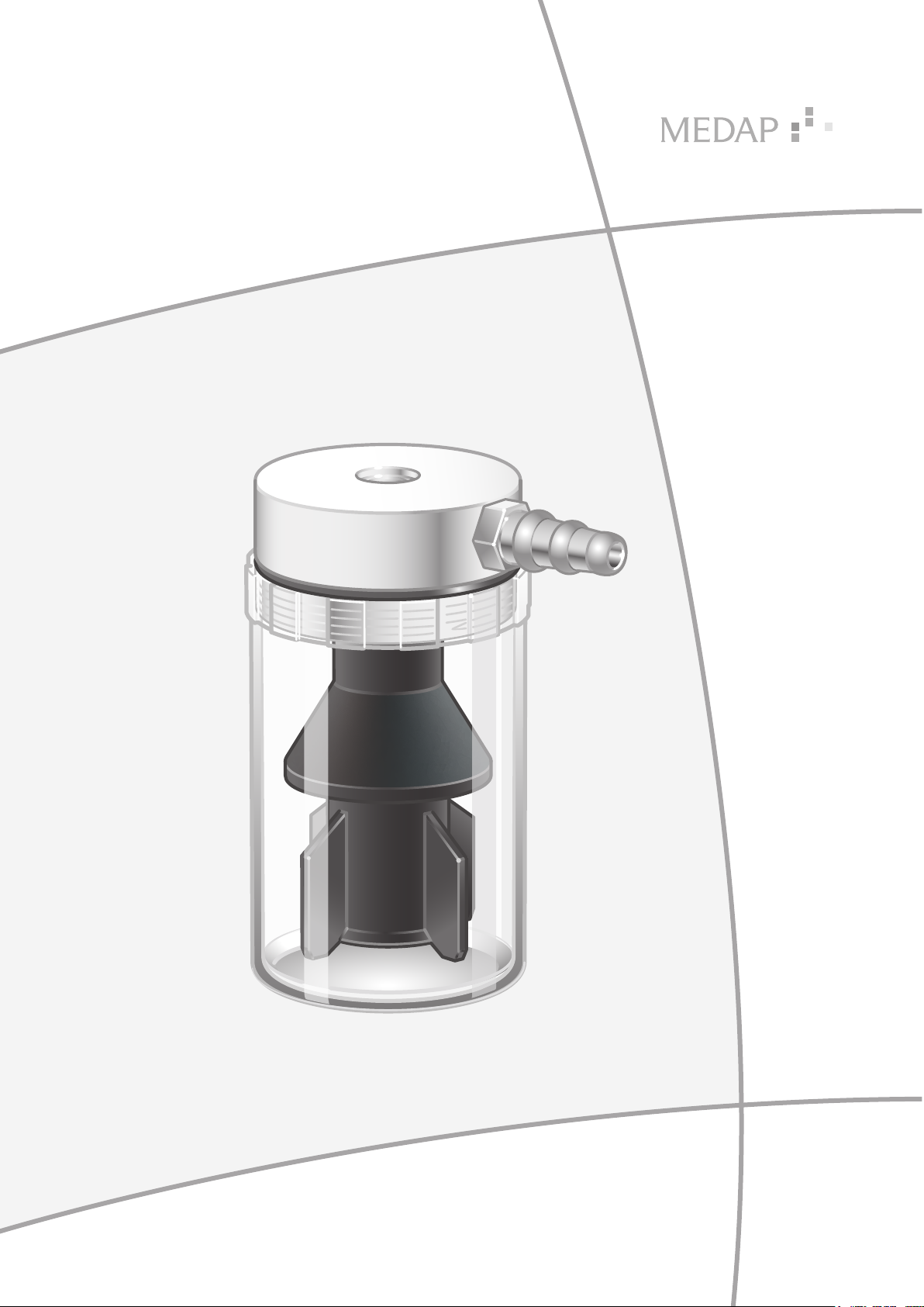
MECHANICAL OVERFLOW PROTECTION
GA 5752 2173 GB 01
Page 2
Subject to technical modification!
Illustrations and technical specifications may vary slightly from those in these Operating
Instructions as a result of ongoing product development.
V01 2020-07
2
GA 5752 2173 GB 01
Page 3

Table of contents
Table of contents
1 Introduction ..............................................................................................................................................5
1.1 Environmental protection ............................................................................................................................5
1.1.1 Packaging ....................................................................................................................................5
1.1.2 ATMOS products .......................................................................................................................... 5
1.2 How to use these operating instructions .................................................................................................... 5
1.2.1 General ........................................................................................................................................5
1.2.2 Symbols .......................................................................................................................................5
1.2.2.1 Actions and responses .............................................................................................. 5
1.2.3 Definitions ....................................................................................................................................6
1.2.3.1 Design of safety notes ............................................................................................... 6
1.2.3.2 Design of other notes ................................................................................................ 6
1.2.4 Symbols used ..............................................................................................................................6
1.3 Basic requirements .....................................................................................................................................7
1.3.1 Use in accordance with the intended purpose ............................................................................. 7
1.3.2 Applicable standards ....................................................................................................................7
1.3.3 Application ...................................................................................................................................8
1.3.4 Interface description .....................................................................................................................8
1.3.4.1 Vacuum connection tube ........................................................................................... 8
2 Safety notes ..............................................................................................................................................9
2.1 General safety notes .................................................................................................................................. 9
3 Initial operation, operation and use ......................................................................................................10
3.1 General .....................................................................................................................................................10
3.2 Equipment inspection ............................................................................................................................... 10
3.3 Mounting the mechanical overflow protection .......................................................................................... 11
3.4 Mounting to the tapping unit ..................................................................................................................... 11
3.5 Dismantling the mechanical overflow protection ...................................................................................... 12
4 Cleaning and disinfection ......................................................................................................................13
4.1 General .....................................................................................................................................................13
4.2 Cleaning ................................................................................................................................................... 14
4.2.1 General ......................................................................................................................................14
4.2.2 Cleaning procedure ....................................................................................................................14
4.3 Disinfection ............................................................................................................................................... 15
4.3.1 General ......................................................................................................................................15
4.3.2 Suitable disinfectants ................................................................................................................. 15
4.3.3 Disinfection procedure ...............................................................................................................16
4.3.4 Disinfection procedures ............................................................................................................. 16
5 Maintenance ............................................................................................................................................17
5.1 General .....................................................................................................................................................17
GA 5752 2173 GB 01
3
Page 4

Table of contents
5.2 Repairs ..................................................................................................................................................... 17
5.3 Service hotline .......................................................................................................................................... 17
5.4 Malfunctions and troubleshooting.............................................................................................................17
5.5 Sending in the device ............................................................................................................................... 17
6 Technical specifications ........................................................................................................................ 19
6.1 Technical specifications ............................................................................................................................ 19
6.2 Ambient conditions ................................................................................................................................... 19
4
GA 5752 2173 GB 01
Page 5

1 Introduction
1.1 Environmental protection
1.1.1 Packaging
The packaging is made of materials compatible with the environment. ATMOS will dispose of the
packaging materials upon request.
1.1.2 ATMOS products
ATMOS will take back used products or those which are no longer in service.
Please contact your ATMOS representative for more detailed information.
1.2 How to use these operating instructions
1.2.1 General
These operating instructions are provided to familiarise you with the features of this ATMOS
product. They are subdivided into several chapters.
Introduction
Environmental protection
1
Please note:
• Please read these operating instructions carefully and completely before using the product for
the first time.
• Always proceed in accordance with the information contained in the operating instructions.
• Store these operating instructions in a location near the product.
1.2.2 Symbols
1.2.2.1 Actions and responses
The ‘’ symbol identifies an action taken by the user, while the ‘’ symbol identifies the reaction
that this will induce in the system.
Example:
Turn on the light switch.
Lamp lights up.
GA 5752 2173 GB 01
5
Page 6
Introduction
1
How to use these operating instructions
1.2.3 Definitions
1.2.3.1 Design of safety notes
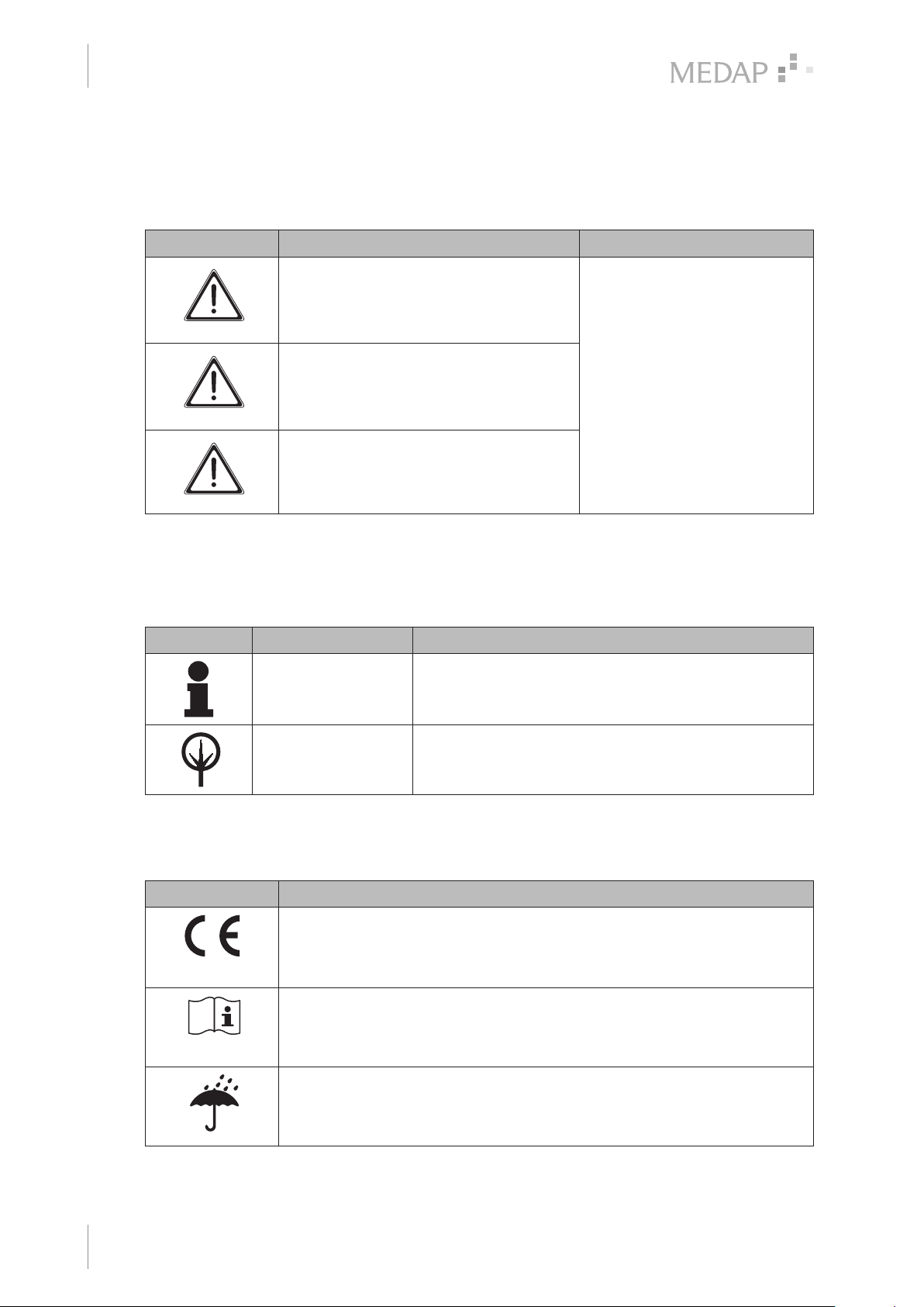
Pictogram Descriptor Text
DANGER!
Indicates a direct and immediate risk to
persons which may be fatal or result in
most serious injury.
WARNING!
Indicates a potential risk to persons or
property which may result in health hazard
or grave property damage.
CAUTION!
Indicates a potential risk to property which
may result in property damage.
The text for the safety note
describes the type of risk and
how to avert it.
Tab. 1: Design of safety notes
1.2.3.2 Design of other notes
Notes not referring to personal injury or property damage are used as follows:
Pictogram Descriptor Reference to
NOTE Additional assistance or further useful information.
ENVIRONMENT Proper disposal.
Tab. 2: Design of other notes
1.2.4 Symbols used
Symbols Identification
Labelling for class I products which were developed and marketed in
compliance with the Medical Devices Directive 93/42/EEC.
6
GA 5752 2173 GB 01
Labelling in compliance with the IEC 60601-1 standard.
Symbol for ‘Follow operating instructions’.
Packaging label.
Symbol for ‘Keep dry’.
Page 7
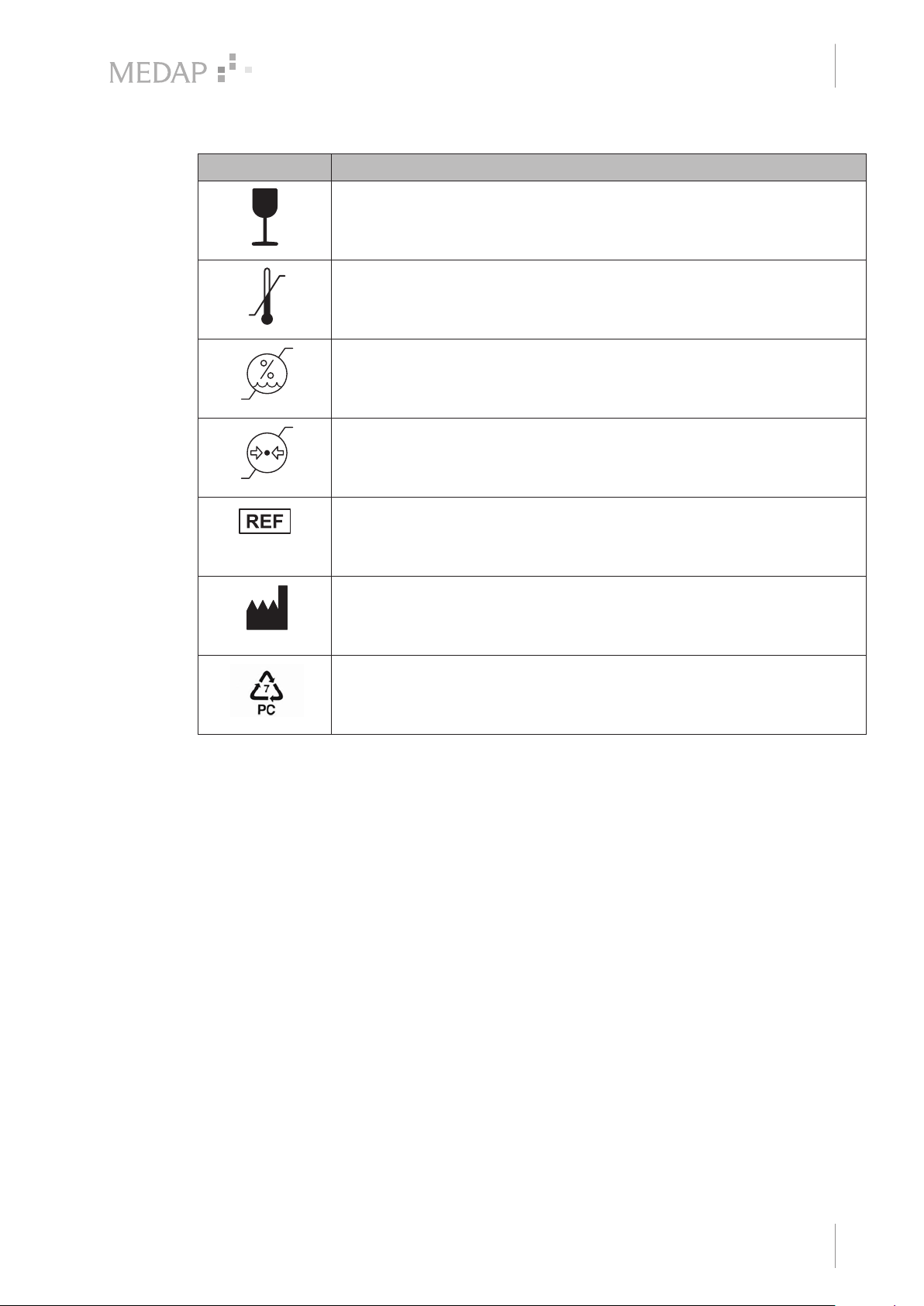
Symbols Identification
Packaging label.
Symbol for ‘Fragile! Handle with care’.
Labelling in compliance with the ISO 15223-1 standard.
Symbol for ‘Temperature limitations’.
Labelling in compliance with the ISO 15223-1 standard.
Symbol for ‘Relative humidity’.
Labelling in compliance with the ISO 15223-1 standard.
Symbol for ‘Atmospheric pressure’.
Introduction
Basic requirements
1
Labelling in compliance with the ISO 15223-1 standard.
Symbol for ‘Order number’.
Labelling in compliance with the ISO 15223-1 standard.
Symbol for ‘Name and address of the manufacturer as well as date of
Tab. 3: Symbols
1.3 Basic requirements
1.3.1 Use in accordance with the intended purpose
The product satisfies the basic requirements set forth in Annex I to Council Directive 93/42/EEC
concerning medical devices (Medical Devices Directive) as well as the applicable national
(German) codes and the Medical Devices Act (MPG) in Germany. In accordance with this
directive, the product may only be used by persons who have been instructed how to use this
product by an authorised person. This product is to be used exclusively for human medicine.
manufacture’.
Material designation for the plastic PC
(Polycarbonate).
Accessories
Accessories or combinations of accessories may be utilised only as and when indicated in these
operating instructions.
Use other accessories, combinations and parts subject to wear only if these are intended
expressly for the application and will not adversely affect performance features or safety
requirements.
1.3.2 Applicable standards
The product satisfies the basic requirements set forth in Annex I to Council Directive 93/42/EEC
concerning medical devices (Medical Devices Directive) as well as the applicable national
(German) codes and the Medical Devices Act (MPG) in Germany.
GA 5752 2173 GB 01
7
Page 8

Introduction
1
Basic requirements
1.3.3 Application
The mechanical overflow protection (REF 5752 1699) is designed for use in connection with
FINA tapping units. The mechanical overflow protection protects the tapping units from
oversuction during the suction process. The mechanical overflow protection device is suitable for
continuous operation. The mechanical overflow protection device can be reused when prepared
accordingly.
1.3.4 Interface description
1.3.4.1 Vacuum connection tube
The vacuum connection tube is used to connect the mechanical overflow protection device and
the septic fluid jar.
Technical specifications
• Shore hardness of 60
• Inner diameter 6–8 mm
• Length 50 cm (± 10 cm)
• Vacuum resistant down to −95 kPa (may not collapse)
Prerequisites
• The vacuum connection tube must comply with the hospital's standards for hygiene.
• The inner diameter of the vacuum connection tube must match the outer diameter of the tube
connector on the aluminium body.
The vacuum connection tube will be referred to only as ‘connection tube’ below.
8
GA 5752 2173 GB 01
Page 9
2 Safety notes
2.1 General safety notes
DANGER!
Defective device!
Using incorrect spare parts or accessories can cause injuries or equipment failure.
Only use original accessories or spare parts.
WARNING!
Infection hazard caused by not using overflow protection or by using an improperly
mounted overflow protection!
Septic fluids will enter the tapping unit during extraction. Discontinue using the
tapping unit. Clean and disinfect the tapping unit and have it repaired by a shop
authorised by ATMOS to do so.
WARNING!
Risk of injury!
Worn or damaged products can cause injuries.
Use only products which are in perfect condition.
Safety notes
General safety notes
2
WARNING!
Overflow protection device!
If the overflow protection device closes during operation, the overflow protection
device, complete with lid, must be removed and a new overflow protection device
must be mounted.
CAUTION!
Oversuction!
Proper functioning of the mechanical overflow protection is only assured when the
product is operated in a vertical position.
Operate the product only in vertical position.
WARNING!
Foaming!
Foam may be created when extracting secretion. Foam may impair the function of
the overflow protection.
Use a commercially available foam inhibitor.
GA 5752 2173 GB 01
9
Page 10
Initial operation, operation and use
3
General
3 Initial operation, operation and use
3.1 General
WARNING!
Risk of injury / property damage!
The product may not be used for the following purposes or under the following
conditions:
• The container of the overflow protection device may not be used as a septic fluid
jar.
• The container of the overflow protection device must not come into contact with
strong acids or alkaline solutions.
• The overflow protection device may not be pressurised with overpressure.
CAUTION!
Property damage!
If the float is not fitted properly in the overflow protection device or if it is not used,
liquid may enter the tapping unit and damage it.
Ensure correct fit of the float.
3.2 Equipment inspection
DANGER!
Equipment inspection!
Only components which are in perfect condition can ensure proper functioning of
the product. The components will thus have to be carefully inspected before
assembly.
Check whether the unit has been properly cleaned and that there are no residues or soiling.
Do not use damaged components. In particular, there must be no cracks in the container.
After assembly, check that the float moves freely, e.g. by shaking the whole overflow
protection device.
10
GA 5752 2173 GB 01
Page 11
Mounting the mechanical overflow protection
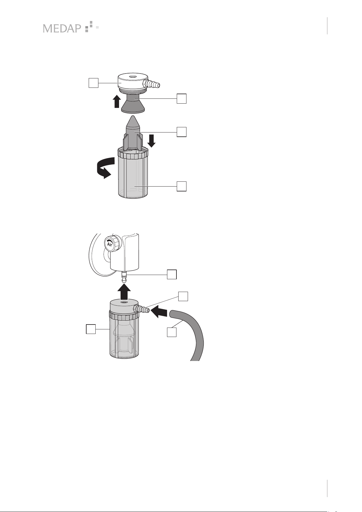
3.3 Mounting the mechanical overflow protection
3
1
2
4
Initial operation, operation and use
3
Mounting the mechanical overflow
protection
Plug the rubber cap (1) onto the aluminium
body (3).
Insert the float (2) with the tip pointed
upwards into the overflow container (4).
Screw the overflow container (4) onto the
aluminium lid (3).
Fig. 1: Mounting the mechanical overflow protection
3.4 Mounting to the tapping unit
1
Fig. 2: Connection of the mechanical overflow pro-
tection device
2
3
4
Connection of the mechanical overflow
protection device
Plug the overflow protection device (1)
directly onto the tube connector (2) on the
housing of the tapping unit and press
upwards until it stops.
Attach the connection tube (3) to the tube
connector (4) of the mechanical overflow
protection device and connect it with the
designated tube connector of the septic
fluid jar.
For disassembly, first remove the
connection tube from the tube connector of
the mechanical overflow protection device.
Then remove the complete overflow
protection device with lid from the tube
connector of the tapping unit. Hold the
tapping unit steady with one hand while
doing so.
GA 5752 2173 GB 01
11
Page 12
Initial operation, operation and use
3
Dismantling the mechanical overflow protection
3.5 Dismantling the mechanical overflow protection
3
1
2
4
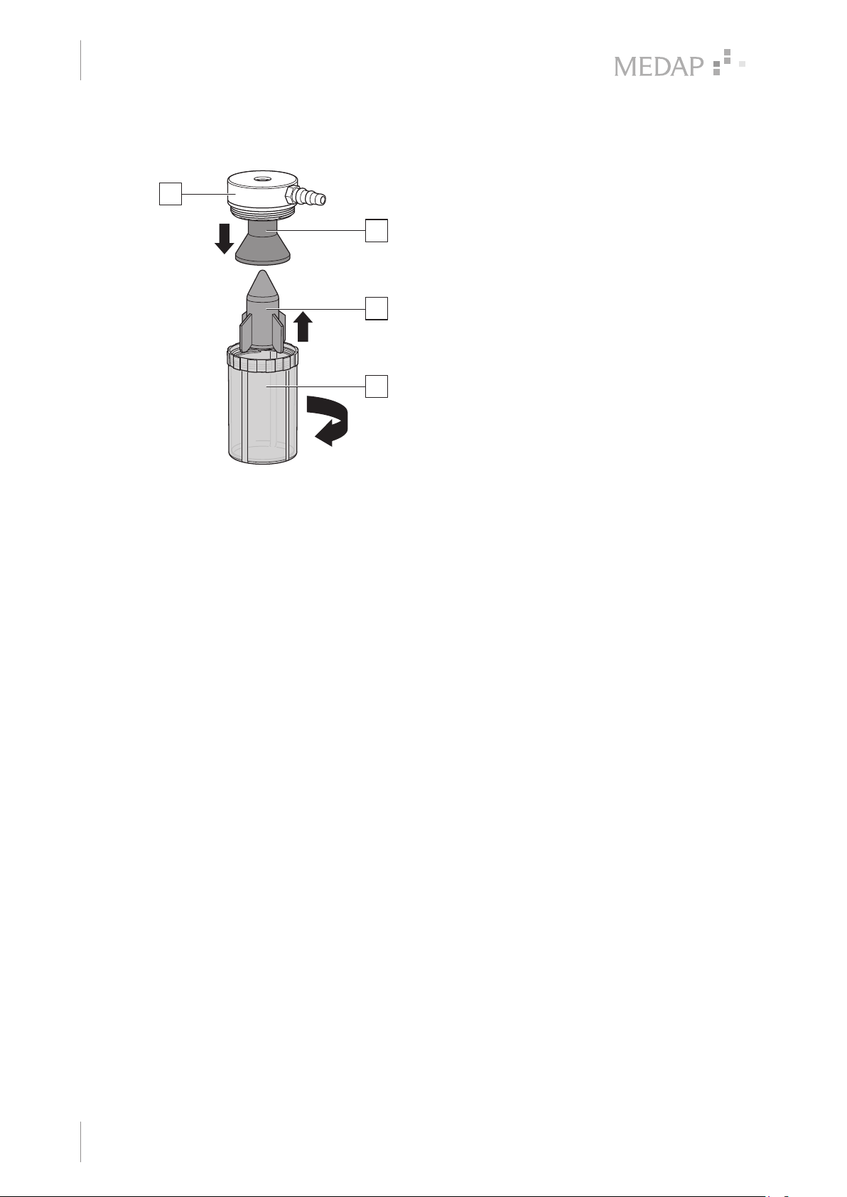
Dismantling the mechanical overflow
protection
Unscrew the overflow container (4) from the
aluminium body (3).
Remove the rubber cap (1) from the
aluminium body (3).
Remove float (2) from the overflow
container (4).
Fig. 3: Dismantling the mechanical overflow protec-
tion
12
GA 5752 2173 GB 01
Page 13
4 Cleaning and disinfection
4.1 General
The product must be cleaned and wipe disinfected after each use.
DANGER!
Risk due to incorrect use of detergents and disinfectants!
It is strictly advised to observe the manufacturer’s instructions regarding how to
use the detergents and disinfectants as well as to observe the valid hospital
hygiene rules.
WARNING!
Infection hazard!
Product may be contaminated.
Always wear gloves for cleaning and disinfection.
WARNING!
Infection hazard!
Particles of grime may become encapsulated and cause the product not to achieve
the desired germ reduction after disinfection.
Before disinfection, the product must be cleaned thoroughly of contamination and
encapsulated particles of grime.
Cleaning and disinfection
General
4
CAUTION!
Improper cleaning and disinfection can cause property damage!
Do not use the following products for cleaning and disinfection:
• Products containing alcohol (e.g. hand disinfectants)
• Halogenides (e.g. fluorides, chlorides, bromides, iodides)
• Dehalogenating compounds (e.g. fluorine, chlorine, bromine, iodine)
• Products that may scratch the surface (e.g. scouring agents, wire brushes, wire
wool)
• Standard commercial solvents (e.g. benzene, thinner)
• Water containing iron particles
• Cleaning sponges containing iron
• Products containing hydrochloric acid
Use approved detergents and disinfectants only. Use a soft, lint-free cloth or a soft
nylon brush to clean the product.
CAUTION!
Improper cleaning and disinfection can cause property damage!
Use only as much detergent and disinfectant as required.
CAUTION!
Improper cleaning and disinfection can cause property damage!
Perform visual and functional inspections after each cleaning and disinfection
process.
GA 5752 2173 GB 01
13
Page 14
Cleaning and disinfection
4
Cleaning
4.2 Cleaning
4.2.1 General
CAUTION!
Property damage due to tension cracks!
Do not treat polysulphone containers with strong acids or alkaline solutions.
NOTE
The container of the overflow protection device, the float, the float cage and the
seals are all disposables. Depending on the cleaning process used, the canister is
subjected to a greater or lesser amount of material-related wear. Check the proper
condition of the container before each use. Replace the container if any damage is
visible.
NOTE
Use only all-purpose cleaners which are slightly alkaline (soap solution) and which
contain surfactants and phosphates as the active cleaning agents.
In the event of heavily contaminated surfaces, use concentrated all-purpose
detergent.
CAUTION!
Improper cleaning can cause property damage!
Residues of physiological saline solutions (e.g. sodium chloride) can attack the
surfaces of the product.
Remove residues of physiological saline solutions with a cloth dampened in clean
water. Then dry the product with a dry, lint-free cloth.
CAUTION!
Improper cleaning can cause property damage!
Do not spray cleaning agent directly into the joints or gaps and never use a highpressure cleaning unit!
4.2.2 Cleaning procedure
Use the correct dose of all-purpose detergent with water for the degree of surface
contamination and in accordance with the detergent manufacturer's instructions.
Thoroughly wipe off the product with a soft cloth slightly dampened in an all-purpose detergent
solution.
Ensure that the product is free of contamination and encapsulated particles of grime.
Wipe the product thoroughly with a soft cloth slightly dampened in clean water.
Ensure that the product is free of detergent residues.
Dry the product with a dry, absorbent and lint-free cloth.
This will help to reduce pathogen growth on the product's surface.
Wipe or spray disinfect the product after each cleaning.
14
GA 5752 2173 GB 01
Page 15
4.3 Disinfection
4.3.1 General
Cleaning and disinfection
Disinfection
NOTE
In the event that product surfaces are very dirty, carry out an additional cleaning
procedure before disinfecting the product.
CAUTION!
Material damage due to excessive exposure times!
Exceeding the prescribed exposure time of the disinfectant may damage the
surfaces.
Observe the exposure time specified by the disinfectant manufacturer.
DANGER!
Infection hazard!
The product is used in the treatment of patients. Contaminated components may
be hazardous to the patient's health.
Prepare the product in accordance with hygiene guidelines before every use!
4
4.3.2 Suitable disinfectants
Only surface disinfectants based on the following combinations of active ingredients may be used
for disinfection:
• Aldehydes
• Quaternary compounds
• Guanidine derivatives
Ingredient group Active ingredients
Aldehydes 2-ethyl-1-hexanal, formaldehyde, glutardialdehyde, glyoxal,
Quaternary compounds Alkyl-didecyl-polyoxethyl ammonium propionate, alkyl-dimethyl-
Guanidine derivatives Alkyl-biguanide, chlorhexidine-digluconate, cocospropylene-
o-phthaldialdehyde, succinaldehyde
alkylbenzyl ammonium chloride, alkyl-dimethyl-ethyl ammonium
chloride, alkyl-dimethyl-ethylbenzyl ammonium chloride,
benzalkonium propionate, benzalkonium chloride (alkyl-dimethylbenzyl ammonium chloride, coco-dimethyl-benzyl ammonium
chloride, lauryl-dimethylbenzyl ammonium chloride, myristyldimethyl-benzyl ammonium chloride), benzethonium chloride,
benzyl-dihydroxyethyl-coco-alkyl ammonium chloride, dialkyldimethyl ammonium chloride (didecyldimethyl ammonium chloride),
didecyl-methyl-oxyethyl ammonium propionate, mecetronium-ethyl
sulfate, methyl-benzethonium chloride, n-octyl-dimethyl-benzyl
ammonium chloride
diamine guanidinium diacetate, oliogomeric biguanide,
polyhexamethylene biguanide hydrochloride (oligo-diimino imiodocarbonyl imino-hexamethylene, polyhexanide)
Tab. 4: Active ingredients of disinfectants
GA 5752 2173 GB 01
15
Page 16
Cleaning and disinfection
4
Disinfection
4.3.3 Disinfection procedure
After each cleaning process, wipe or spray disinfect the product in accordance with the
disinfectant manufacturer’s instructions.
Ensure that the product is free of disinfectant residue.
Perform visual and functional inspections.
4.3.4 Disinfection procedures
Equipment components Wipe, spray disinfection
Overflow container X
Aluminium lid X
Float / rubber cap X
O-ring X
Tab. 5: Disinfection procedures
1
Before disinfection, remove contamination and residues from the parts and dry well.
1
16
GA 5752 2173 GB 01
Page 17
5 Maintenance
5.1 General
Maintenance, repairs and periodic tests may only be carried out by persons who have the
appropriate technical knowledge and are familiar with the product. To carry out these measures,
the person must have the necessary test devices and original spare parts.
ATMOS recommends: work should be carried out by an authorised ATMOS service partner. This
ensures that repairs and testing are carried out professionally, original spare parts are used and
warranty claims remain unaffected.
5.2 Repairs
The following issues may require repairs by the manufacturer or an authorised service partner:
• Liquid has penetrated the device.
• Performance has significantly decreased.
• Inexplicable notifications appear.
• Abnormal noises occur.
• Functional faults cannot be rectified according to the measures in chapter Malfunctions and
troubleshooting [ page 17].
If defects are detected, the product may not be used any longer.
Make a note of the defects and the REF number on the type plate and inform your ATMOS
representative.
Observe the information in chapter Sending in the device [ page 17].
Maintenance
General
5
5.3 Service hotline
+49 7653 689-0
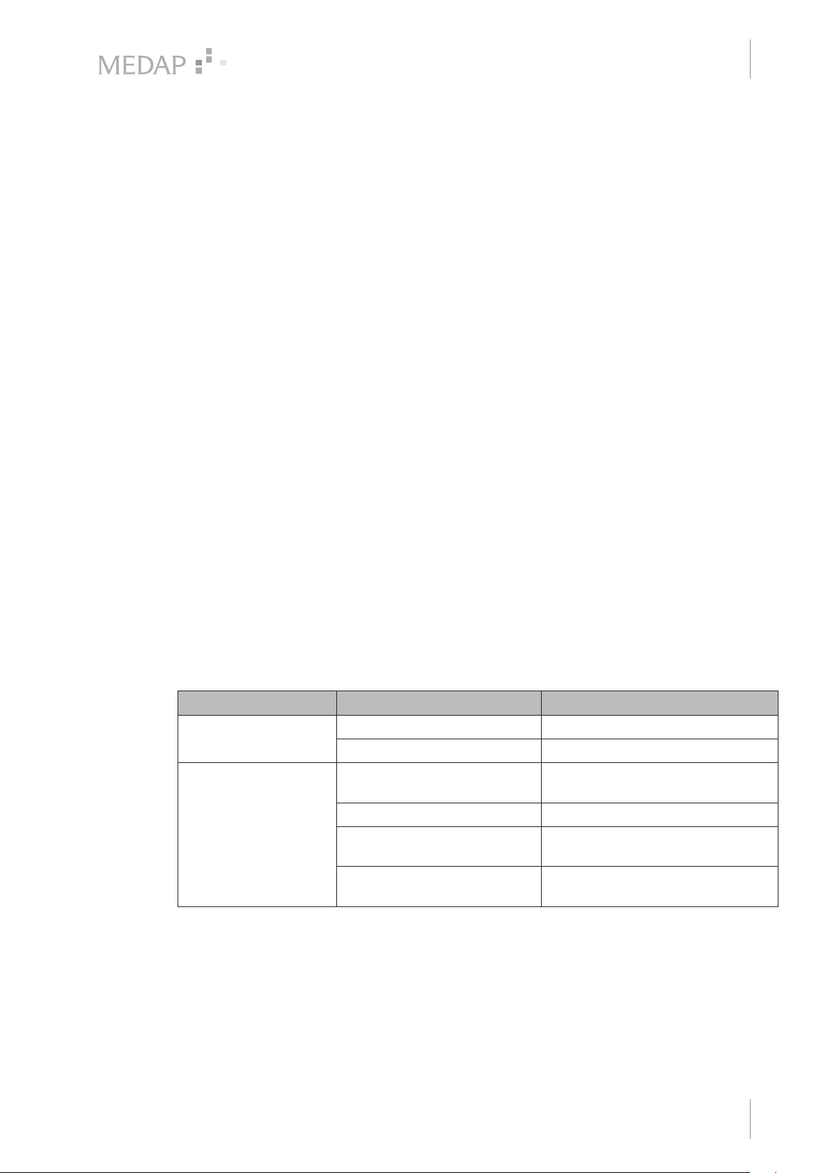
5.4 Malfunctions and troubleshooting
Defect Source of malfunction Troubleshooting
Reduced or no flow rate Seals damaged Replace seals
Aspiration system is leaking Check aspiration system
Oversuction of the
tapping unit despite
overflow protection
Tab. 6: Troubleshooting
5.5 Sending in the device
Remove and properly dispose of consumables.
Clean and disinfect the product and accessories according to the operating instructions.
Place used accessories with the product.
Foaming Use commercially available foam
Seals damaged Replace seals
Tapping unit mounted at an
angle
Overflow protection device
contaminated
inhibitor
Operate tapping unit in horizontal
position only
Clean the overflow protection device
GA 5752 2173 GB 01
17
Page 18

5
Maintenance
Sending in the device
Fill in form QD 434 ‘Delivery complaint / return shipment’ and the respective decontamination
certificate.
This form is enclosed with each delivery and can be found at www.atmosmed.com.
The device must be well padded and packed in suitable packaging.
Place the form QD 434 ‘Delivery complaint / return shipment’ and the respective
decontamination certificate in an envelope.
Affix the envelope to the outside of the package.
Send the product to ATMOS or to your dealer.
18
GA 5752 2173 GB 01
Page 19
6 Technical specifications
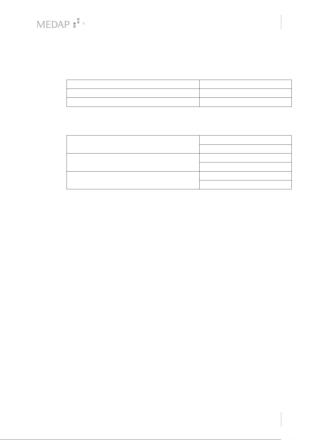
6.1 Technical specifications
Weight approximately 160 g
Dimensions (W x H x D) approximately 50 x 96 x 80 mm
Pressure range −100 to 0 kPa*
* 100 kPa = 1 bar = 1000 mbar = 750 mmHg
6.2 Ambient conditions
Temperature −40 °C to +60 °C (shipping)
Relative humidity 10% to 95% (shipping)
Technical specifications
Technical specifications
+10 °C to +40 °C (operation)
30% to 75% (operation)
6
Atmospheric pressure 500 hPa to 1050 hPa (shipping)
500 hPa to 1050 hPa (operation)
GA 5752 2173 GB 01
19
Page 20

Manufacturer:
Acare Technology Co., Ltd
5F.-4, No.24, Wuquan 2nd Rd.
Xinzhuang Dist.,
New Taipei City 242 Taiwan
Distributor:
ATMOS
MedizinTechnik GmbH & Co. KG
Ludwig-Kegel-Str. 16
79853 Lenzkirch
GERMANY
Phone: +49 7653 689-0
www.atmosmed.com
 Loading...