

Page 1
OPERATING INSTRUCTIONS
MEDAP
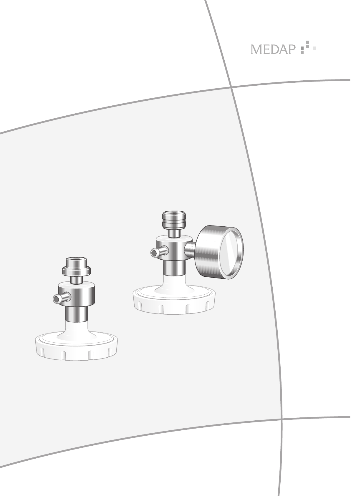
GAS-JET PUMPS
GA 5750 4196 GB 15
Page 2

Subject to technical modification!
4
Illustrations and technical specifications may vary slightly from those in these Operating
Instructions as a result of ongoing product development.
V15 2020-05
2
GA 5750 4196 GB 15
Page 3

Table of contents
Table of contents
1 Introduction ..............................................................................................................................................5
1.1 Foreword .................................................................................................................................................... 5
1.2 Environmental protection ............................................................................................................................5
1.2.1 Packaging ....................................................................................................................................5
1.2.2 ATMOS products .......................................................................................................................... 5
1.3 Disposal ......................................................................................................................................................5
1.4 How to use these operating instructions .................................................................................................... 5
1.4.1 General ........................................................................................................................................5
1.4.2 Abbreviations ...............................................................................................................................5
1.4.3 Symbols .......................................................................................................................................5
1.4.3.1 Cross-references ....................................................................................................... 5
1.4.3.2 Actions and responses .............................................................................................. 6
1.4.4 Definitions ....................................................................................................................................6
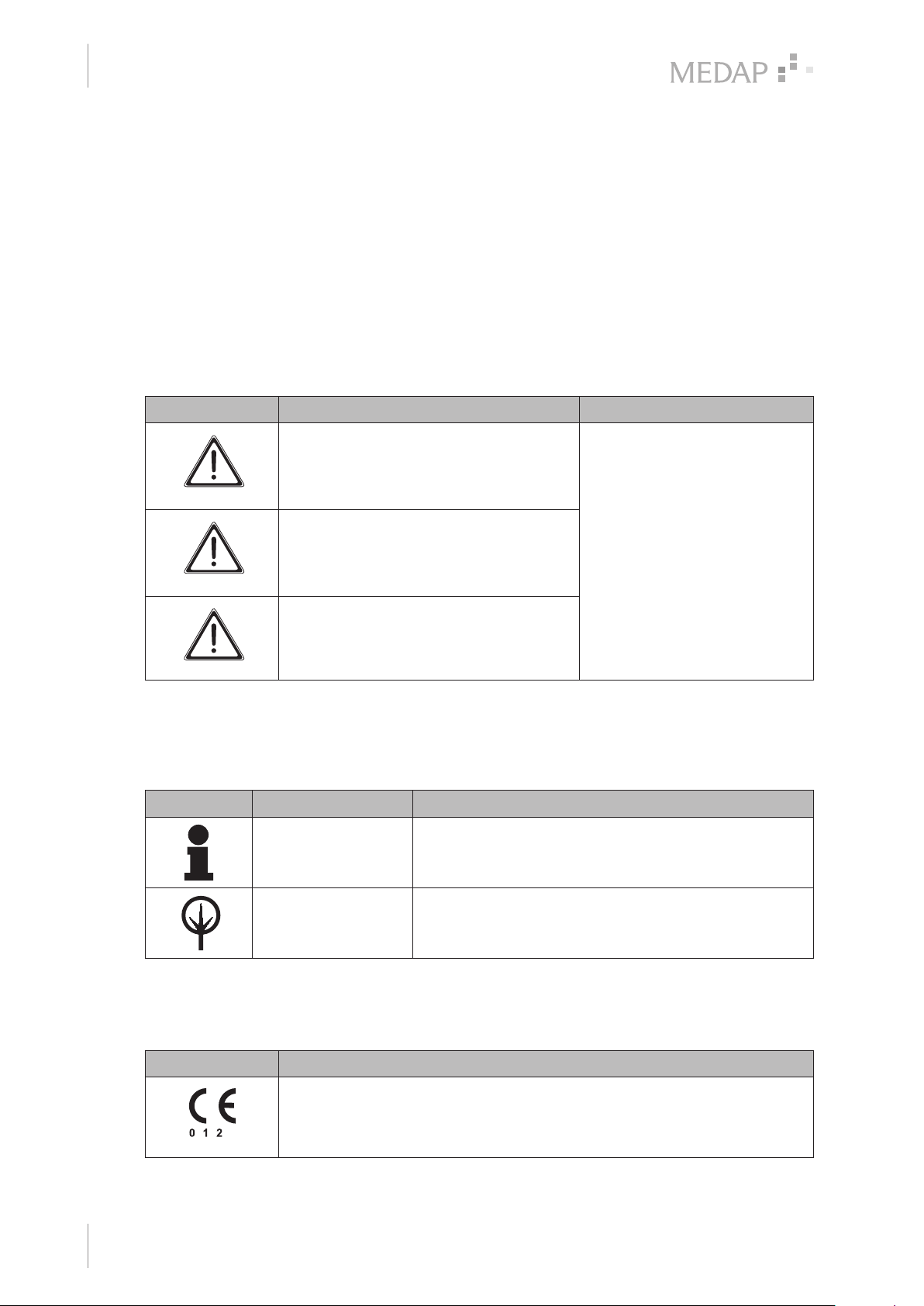
1.4.4.1 Design of safety notes ............................................................................................... 6
1.4.4.2 Design of other notes ................................................................................................ 6
1.4.5 Symbols used ..............................................................................................................................6
1.5 Basic requirements .....................................................................................................................................8
1.5.1 Overview of gas-jet pump without gauge ..................................................................................... 8
1.5.2 Overview of gas-jet pump with gauge .......................................................................................... 9
1.5.3 Use in accordance with the intended purpose ............................................................................. 9
1.5.4 Applicable standards ..................................................................................................................10
1.5.5 Intended purpose ....................................................................................................................... 10
1.5.5.1 Possible applications ............................................................................................... 11
1.5.6 Interface description ................................................................................................................... 11
1.5.6.1 General .................................................................................................................... 11
1.5.6.2 Dimensions for the gas type specific connection for compressed gas .................... 11
1.5.6.3 Fine regulator .......................................................................................................... 11
1.5.6.4 Overflow protection device ...................................................................................... 11
1.5.6.5 Vacuum connection tube ......................................................................................... 12
1.5.6.6 Hydrophobic bacterial and viral filter ....................................................................... 12
1.5.6.7 Fingertip ...................................................................................................................12
1.5.6.8 Applicator (lance, suction tip, etc.) ........................................................................... 12
1.5.6.9 Septic fluid jar including septic fluid jar cap ............................................................. 12
1.5.6.10 Suction tube, Shore hardness 60 ............................................................................ 12
1.5.7 Versions .....................................................................................................................................13
1.5.7.1 Gas-jet pump without gauge .................................................................................... 13
1.5.7.2 Gas-jet pump with gauge ......................................................................................... 13
2 Principal safety notes ............................................................................................................................14
2.1 Principal safety notes ............................................................................................................................... 14
GA 5750 4196 GB 15
3
Page 4

Table of contents
3 Initial operation .......................................................................................................................................17
3.1 General .....................................................................................................................................................17
3.2 Equipment inspection ............................................................................................................................... 17
3.3 Assembly of gas-jet pump ........................................................................................................................ 18
3.3.1 Operation with hydrophobic bacterial and viral filter .................................................................. 18
3.3.2 Operation without a hydrophobic bacterial and viral filter .......................................................... 19
4 Operation ................................................................................................................................................20
4.1 Gas-jet pump with gauge .........................................................................................................................20
4.2 Disassembly of gas-jet pump ................................................................................................................... 20
4.3 Replacing the bacterial filter paper .......................................................................................................... 21
5 Cleaning and disinfection ......................................................................................................................22
5.1 General .....................................................................................................................................................22
5.2 Cleaning ................................................................................................................................................... 23
5.2.1 General ......................................................................................................................................23
5.2.2 Cleaning procedure ....................................................................................................................23
5.3 Disinfection ............................................................................................................................................... 23
5.3.1 General ......................................................................................................................................23
5.3.2 Suitable disinfectants ................................................................................................................. 24
5.3.3 Disinfection procedure ...............................................................................................................24
5.3.4 Disinfection procedures ............................................................................................................. 24
5.4 Product-specific safety notes ...................................................................................................................25
6 Maintenance ............................................................................................................................................26
6.1 General .....................................................................................................................................................26
6.2 Periodic tests ............................................................................................................................................ 26
6.3 Malfunctions and troubleshooting.............................................................................................................26
6.4 Repairs ..................................................................................................................................................... 27
6.5 Service hotline .......................................................................................................................................... 27
6.6 Sending in the device ............................................................................................................................... 27
7 Technical specifications ........................................................................................................................ 28
7.1 General .....................................................................................................................................................28
7.2 Ambient conditions ................................................................................................................................... 28
7.3 Dimensions and weight ............................................................................................................................ 28
8 Accessories ............................................................................................................................................ 29
8.1 Accessories .............................................................................................................................................. 29
8.2 Consumables ...........................................................................................................................................29
4
GA 5750 4196 GB 15
Page 5
1 Introduction
1.1 Foreword
Your facility has selected the leading-edge medical technology made by ATMOS. We sincerely
appreciate the trust you have placed in us.
1.2 Environmental protection
1.2.1 Packaging
The packaging is made of materials compatible with the environment. ATMOS will dispose of the
packaging materials upon request.
1.2.2 ATMOS products
ATMOS will take back used products or those which are no longer in service. Please contact your
ATMOS representative for more detailed information.
Introduction
Foreword
1
1.3 Disposal
WARNING!
Disposal!
The product is used in the treatment of patients. The product or some of its
components may be contaminated after use.
Clean and disinfect the product before disposal.
1.4 How to use these operating instructions
1.4.1 General
These operating instructions are provided to familiarise you with the features of this ATMOS
product. They are subdivided into several chapters.
Please note:
• Please read these operating instructions carefully and completely before using the product for
the first time.
• Always proceed in accordance with the information contained herein.
• Store these operating instructions in a location near the product.
1.4.2 Abbreviations
EN European standard
EEC European Economic Community
1.4.3 Symbols
1.4.3.1 Cross-references
References to other pages in these operating instructions are identified with a double arrow
symbol ‘’.
GA 5750 4196 GB 15
5
Page 6
Introduction
4
1
How to use these operating instructions
1.4.3.2 Actions and responses
The ‘’ symbol identifies an action taken by the user, while the ‘’ symbol identifies the reaction
that this will induce in the system.
Example:
Turn on the light switch.
Lamp lights up.
1.4.4 Definitions
1.4.4.1 Design of safety notes
Pictogram Descriptor Text
DANGER!
Indicates a direct and immediate risk to
persons which may be fatal or result in
most serious injury.
The text for the safety note
describes the type of risk and
how to avert it.
WARNING!
Indicates a potential risk to persons or
Tab. 1: Design of safety notes
1.4.4.2 Design of other notes
Notes not referring to personal injury or property damage are used as follows:
Pictogram Descriptor Reference to
Tab. 2: Design for other notes
property which may result in health hazard
or grave property damage.
CAUTION!
Indicates a potential risk to property which
may result in property damage.
NOTE Supplementary assistance or further useful information.
ENVIRONMENT Information regarding proper disposal.
1.4.5 Symbols used
Symbols Identification
6
GA 5750 4196 GB 15
Labelling for products which were developed and are marketed in
compliance with the Medical Devices Directive 93/42/EEC. Class Is, Im, IIa,
IIb and III products are also marked with the identifying number for the
Notified Body.
Page 7
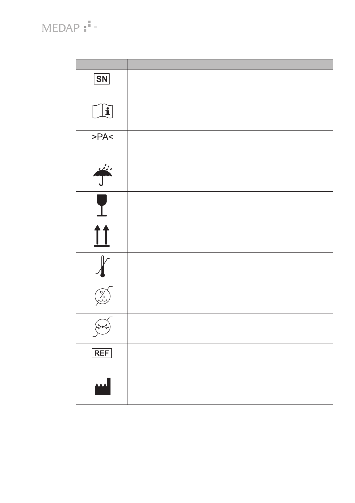
Symbols Identification
Labelling in compliance with the ISO 15223-1 standard.
Symbol for ‘Serial number’.
Labelling in compliance with the IEC 60601-1 standard.
Symbol for ‘Follow operating instructions’.
Introduction
How to use these operating instructions
1
Material designation for the plastic PA (polyamide).
Packaging label.
Symbol for ‘Keep dry’.
Packaging label.
Symbol for ‘Fragile! Handle with care’.
Packaging label.
Symbol for ‘Top’.
Labelling in compliance with the ISO 15223-1 standard.
Symbol for ‘Temperature limitations’.
Labelling in compliance with the ISO 15223-1 standard.
Symbol for ‘Relative humidity’.
Tab. 3: Symbols
Labelling in compliance with the ISO 15223-1 standard.
Symbol for ‘Atmospheric pressure’.
Labelling in compliance with the ISO 15223-1 standard.
Symbol for ‘Product number’.
Labelling in compliance with the ISO 15223-1 standard.
Symbol for ‘Name and address of the manufacturer as well as date of
manufacture’.
GA 5750 4196 GB 15
7
Page 8
Introduction
1
2
3
4
5
6
7
8
1
Basic requirements
1.5 Basic requirements
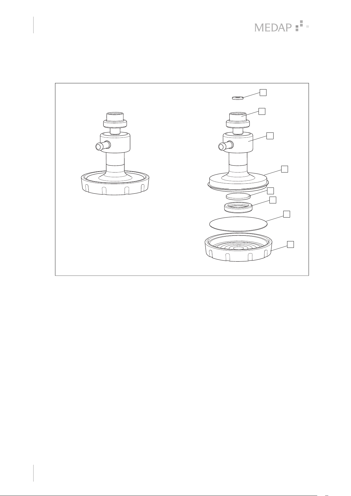
1.5.1 Overview of gas-jet pump without gauge
8
7
6
5
Fig. 1: Overview of gas-jet pump without gauge
1 Bacterial filter cap 5 Bacterial filter housing
2 Bacterial filter paper 6 Housing
3 Seal VITON 7 Cap nut G3/8" (O2) / M18x1 (AIR)
4 Sintered filter 8 Seal
4
3
2
1
8
GA 5750 4196 GB 15
Page 9
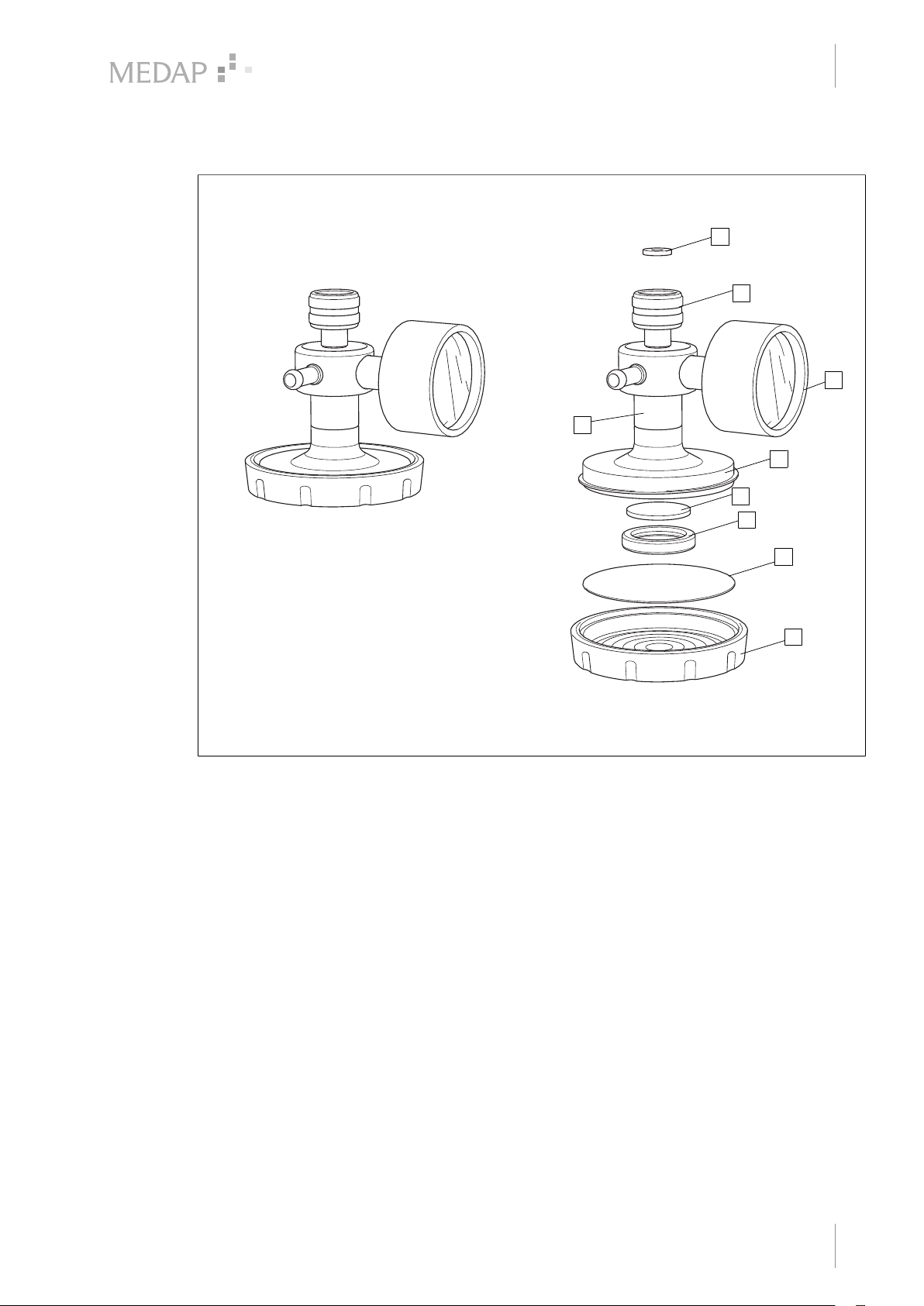
1.5.2 Overview of gas-jet pump with gauge
1
2
3
4
5
6
7
8
9
Introduction
Basic requirements
8
7
9
5
4
3
1
6
Fig. 2: Overview of gas-jet pump with gauge
1 Bacterial filter cap 6 Gauge
2 Bacterial filter paper 7 Cap nut G3/8" (O2) / M18x1 (AIR)
3 Seal VITON 8 Seal
4 Sintered filter 9 Housing
5 Bacterial filter housing
1.5.3 Use in accordance with the intended purpose
Product
As per Annex IX to the Medical Devices Directive 93/42/EEC, this product belongs to class IIa. In
accordance with this directive, the product may only be used by persons who have been
instructed how to use this product by an authorised person. This product is to be used exclusively
for human medicine. When employed in commercial or business use, this product must be
entered in the inventory.
Accessories
Accessories or combinations of accessories may be utilised only as and when indicated in these
operating instructions. Other accessories, combinations of accessories and consumable items
may be used only if they have a valid certification, are intended expressly for the particular use
and will not adversely affect performance, the prescribed ambient conditions or safety
requirements.
2
1
GA 5750 4196 GB 15
9
Page 10

Introduction
1
Basic requirements
1.5.4 Applicable standards
The product satisfies the basic requirements set forth in Annex I to Council Directive 93/42/EEC
concerning medical devices (Medical Devices Directive) as well as the applicable national
(German) codes and the Medical Devices Act (MPG) in Germany. This is certified by compliance
with harmonised standards such as IEC 60601-1 and related standards and the respective
special sections.
1.5.5 Intended purpose
Name: Gas-jet pumps
Main function: Aspiration of secretion, blood, serous fluids, vomit and rinsing fluids
along with any contained particles.
Medical indications /
application:
Specification of the main
function:
User profile: Doctor, medically trained staff
Patient groups: Patients of all ages
Application organ: Natural and artificial body orifices
Application time: Product designed for continuous operation; in practice, short-term
Application site: The application site is the clinical environment and doctor’s
For all applications which require aspiration, e.g. general surgeries
(e.g. aspiration of wound cavities, abscesses) and bronchial
aspiration and where a flow rate of 32 l/min or 12 l/min,
respectively, is sufficient.
The gas-jet pump has a media-coded screw connection either to
the outlet of a fine regulator for compressed air or to the outlet of a
fine regulator for oxygen. The gas-jet pump converts compressed
air or oxygen, respectively, into vacuum via Venturi principle. When
using a version without an integrated vacuum gauge in systems
with controllable vacuum, a separate vacuum gauge must be
connected between the gas-jet pump and the septic fluid jar. The
permissible nominal pressure is 500 kPa ± 10%. A septic fluid jar,
which has to be used, allows a temporary collection of the derived
body fluids.
use on the patient (< 30 days)
practices. The product may only be applied by medically trained
and instructed staff.
10
Contraindications: The gas-jet pumps may not be used:
• Outside the medical sector
• In MR areas
• In the home care sector
• Being operated directly by the patient
• For vacuum extraction
• For the aspiration of flammable or explosive liquids
• For the aspiration of smoke that is generated during HF and
laser surgery without the connection of an intermediate smoke
filter
• For drainages and thoracic drainages
• With a supply pressure other than 500 kPa ± 10%
The product is: Active
GA 5750 4196 GB 15
Page 11

Sterility: Not a sterile product
Introduction
Basic requirements
1
Single-use product /
reprocessing:
1.5.5.1 Possible applications
The gas-jet pump may be operated in combination with a fine regulator:
• Fine regulator AIR (REF 5752 3708 - 5752 3710):
The volumetric flow delivered to the gas-jet pump AIR HF/HV (REF 5750 7542) is regulated by
means of fine regulator AIR.
• Fine regulator O2 (REF 5752 3705):
The volumetric flow delivered to the gas-jet pump O2 LF/HV (REF 5750 7540) and LF/HV with
gauge (REF 5750 7543) is regulated by means of fine regulator O2.
1.5.6 Interface description
1.5.6.1 General
All devices and accessories which are combined with the tapping unit must be listed in the
accessories list or meet the specifications of the interface description. The configuration of the
overall system as well as functional testing are subject to the overall responsibility of the medical
staff.
Functionality and suitability of the connected accessory for each intended application must be
checked by the operator before every use. This includes the functionality of the connector
components, airtightness and suitability regarding material properties, working pressure and flow
rate.
The product and parts of the accessories are reusable. For
information on reprocessing, cleaning and disinfection, please see
the operating instructions.
1.5.6.2 Dimensions for the gas type specific connection for compressed gas
The geometric gas coding for the screw connectors of the gas-jet pump depends on the product
version and is in accordance with national MEDAP factory standards for AIR: M18x1; O2: G3/8".
1.5.6.3 Fine regulator
The fine regulator is used to regulate the volumetric flow applied to the oxygen gas-jet pumps.
The fine regulator is connected to a central gas supply system (CGSS) pursuant to DIN EN ISO
7396-1, DIN EN 737-3 or DIN 13260-1.
Prerequisites
• Fine regulator AIR: Thread M18x1
• Fine regulator O2: Thread G3/8"
1.5.6.4 Overflow protection device
The mechanical overflow protection system protects the vacuum source against oversuction. If
no overflow protection system is integrated in the vacuum source or suction set, a separate
mechanical overflow protection must be connected between the vacuum source and the suction
set.
Prerequisites
• Connections of the overflow protection system must match the inner diameter of the connection tube.
GA 5750 4196 GB 15
11
Page 12

Introduction
1
Basic requirements
1.5.6.5 Vacuum connection tube
The vacuum connection tube is used to connect the gas-jet pump and the septic fluid jar.
Technical specifications
• Shore hardness of 60
• Inner diameter 6–7 mm
• Tube length maximum 50 cm ± 10 cm
• Vacuum resistant down to −95 kPa (must not collapse)
Prerequisites
• The inner diameter of the vacuum connection tube should match the outer diameter of the
tube connector on the septic fluid jar cap of the pump.
The vacuum connection tube will be referred to only as "connection tube" below.
1.5.6.6 Hydrophobic bacterial and viral filter
The hydrophobic bacterial and viral filter protects against contaminants which could be present in
the form of particles or aerosols in the gas drawn in. Moreover, the hydrophobic filter serves as
protection against oversuction; the filter closes off the flow of gas to the product in the event of
oversuction. In its function as bacterial and viral filter, it protects the interior of the pump from the
ingress of bacteria and viruses. This ATMOS product (REF 5750 0630) is a hydrophobic bacterial
and viral filter with a pore size of 1.0 μm (disposable article).
Prerequisites
• Pore size ≤ 1.0 μm.
• Use a bacterial filter suitable for the particular application.
• The tube connector must match the tube being used.
• The hydrophobic filter must close tightly against water passage at an absolute pressure of up
to 10 kPa.
1.5.6.7 Fingertip
The fingertip serves to vent the suction tube in order to be able to quickly interrupt the aspiration
process. It must be possible to sterilise the fingertip or it must be a sterilised disposable item. The
outer diameter of the tube connector must match the inner diameter of the suction tube.
1.5.6.8 Applicator (lance, suction tip, etc.)
The outer diameter of the applicator connection must match the inner diameter of the suction
tube; the utensil must be sterilisable or a sterilised disposable item.
1.5.6.9 Septic fluid jar including septic fluid jar cap
Low leakage; volumes of 0.7 to 5.0 l; the outer diameter of the tube connector for the vacuum
source must match the inner diameter of the connection tube; it must be possible to fix the septic
fluid jar securely to a support or on an equipment rail.
1.5.6.10 Suction tube, Shore hardness 60
The suction tube acts as the connection between the septic fluid jar and the utensil: the suction
tube (1.3–3.0 m in length) must not collapse; the outer diameter of the patient side of the tube
connector on the septic fluid jar must match the inner diameter of the suction tube.
12
GA 5750 4196 GB 15
Page 13

1.5.7 Versions
1.5.7.1 Gas-jet pump without gauge
• Gas-jet pump O2, low flow / high vac (REF 5750 7540)
• Gas-jet pump AIR, high flow / high vac (REF 5750 7542)
1.5.7.2 Gas-jet pump with gauge
• Gas-jet pump with gauge O2, low flow / high vac (REF 5750 7543)
Introduction
Basic requirements
1
GA 5750 4196 GB 15
13
Page 14
Principal safety notes
2
Principal safety notes
2 Principal safety notes
2.1 Principal safety notes
DANGER!
Infection hazard due to use of oversucked filter!
Do not use oversucked hydrophobic filter. Replace oversucked hydrophobic filter.
DANGER!
Incorrect use can result in fatalities!
Instructions for using components made by other manufacturers are not part of
these operating instructions.
Ensure that the manufacturer's instructions are followed.
DANGER!
UV radiation!
Exposure to UV rays can cause material fatigue. The stability would no longer be
ensured.
Do not expose the product to strong UV light.
DANGER!
Fire/explosion hazard!
Air, oxygen and oxygen compounds react explosively with oils, greases and
lubricants. Fire and explosion hazard due to compressed gases.
Keep product, in particular for oxygen, free of oils, greases, lubricants and hand
cream. Only use lubricants which are approved by ATMOS. Observe fire protection
regulations when dealing with flammable gases. Contact Technical Services about
any leakages in the product.
DANGER!
Risk of fire!
Escaping oxygen increases the risk of fire.
Never smoke near equipment which carries oxygen and avoid using open fires or
glowing objects. Check the connector for leaks and tight fit when mounting
accessories.
DANGER!
Risk of fire!
The product may ignite if the maximum operating pressure or the maximum
operating temperature is exceeded.
Do not exceed the maximum operating pressure or maximum operating
temperature.
14
DANGER!
Health hazard!
Only use the product with central gas supply systems in accordance with DIN EN
ISO 7396-1, DIN EN 737-3 or DIN 13260-1 which are equipped with an alarm
facility for improper operating pressures.
GA 5750 4196 GB 15
Page 15
Principal safety notes
Principal safety notes
DANGER!
Health hazard!
Only connect the product to compressed gas cylinders with filling level indication
and pressure reducer. The humidifier can only be used in conjunction with units
which are equipped with a pressure reducer in accordance with DIN EN ISO
10524-1 or DIN EN 738-1.
DANGER!
Defective device!
Using incorrect spare parts or accessories can cause injuries or equipment failure.
Only use original accessories or spare parts.
DANGER!
Health hazard!
Pay attention that the product is connected to the appropriate gas type and that the
screw connection is firmly secured.
2
DANGER!
Danger to life!
The product is not suitable for drainage.
WARNING!
Risk of injury!
Worn or damaged products can cause injuries.
Use only products which are in perfect condition.
WARNING!
Malfunction!
Do not expose the product to torsion, as this might impair its proper function.
Mount accessories in such a way that they remain torsion-free and tension-free.
WARNING!
Ambient conditions!
If the ambient temperature range specified for shipping, operation and/or storage
conditions is undercut or exceeded, then no guarantee can be assumed for the
accuracy, mechanical strength or sealing of the product.
WARNING!
Configuration of the overall system!
The configuration of the overall system as well as the functional testing are subject
to the overall responsibility of the medical staff. The operator must check proper
functionality and suitability of the product for each intended application before
every use, in particular connection parts, tightness and suitability concerning
material, work pressure and flow.
WARNING!
Risk of injury!
Products which are improperly mounted can loosen and cause injuries.
Mount the product properly.
GA 5750 4196 GB 15
15
Page 16
2
Principal safety notes
Principal safety notes
WARNING!
Vacuum gauge!
Never expose vacuum gauge to any shocks as sensitive precision components
may be damaged.
WARNING!
Oversuction!
If septic fluid gets into the unit, it must be shut down immediately and then cleaned
and/or repaired by authorised service personnel.
WARNING!
Risk of injury!
Hazard resulting from incorrect handling.
Follow the operating instructions for all accessories.
CAUTION!
Property damage due to oversuction!
The product may only be operated with the overflow protection in place as
otherwise oversuction could occur. A hydrophobic filter offers an additional
protection against oversuction; in case of oversuction, it shuts off the gas supply to
the product. Particles in the gaseous phase may clog the hydrophobic filter.
ATMOS offers a bacterial and viral filter which also protects the inside of the pump
from entering bacteria and viruses.
WARNING!
Risk of injury!
The suction and aspiration of laser or coagulation vapours (protein-containing
vapours) require the use of a flue gas filter which is appropriate for the specific
application.
16
GA 5750 4196 GB 15
Page 17
3 Initial operation
3.1 General
DANGER!
Observe hygiene guidelines!
Contaminated components may be hazardous to the patient's health.
Prepare the product according to the hygiene guidelines before using it for the first
time. Clean and disinfect the product.
DANGER!
Equipment inspection!
Only components which are in perfect condition can ensure proper functioning of
the product. The components will thus have to be carefully inspected before using
the unit.
CAUTION!
Property damage due to foaming!
Foam may be created when extracting secretion. Foam is detrimental to the
functioning of the mechanical overflow protection. This gives rise to the risk of
secretions entering and damaging the aspirator.
Always use a hydrophobic bacterial and viral filter and, if possible, a commercially
available foam inhibitor.
Initial operation
General
3
NOTE
Refer to the manufacturer's instructions for additional information on the use of the
septic fluid jar and the extraction utensil.
3.2 Equipment inspection
Ensure that the thread of the oxygen gas-jet pump matches the thread of the fine regulator.
Check whether the unit has been properly cleaned and that there are no residues or soiling.
Do not use damaged components.
GA 5750 4196 GB 15
17
Page 18
Initial operation
1
2
1
3
4
2
3
Assembly of gas-jet pump
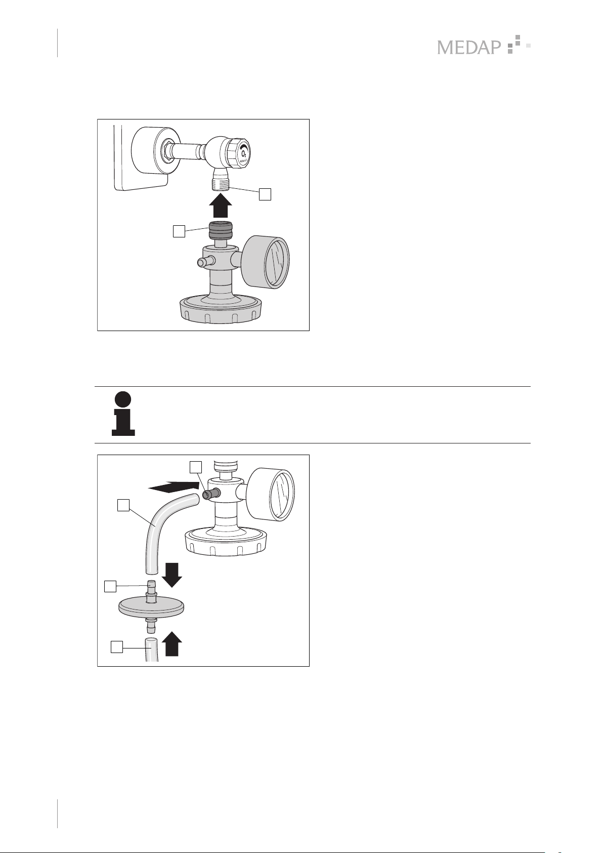
3.3 Assembly of gas-jet pump
1
Mounting the oxygen gas-jet pump
Ensure that a flat seal is located in the
tapped hole of the cap nut (1) of the oxygen
gas-jet pump.
Screw the cap nut of the oxygen gas-jet
2
pump onto the outlet (2) of the fine
regulator.
The oxygen gas-jet pump is mounted on
the fine regulator.
Fig. 3: Mounting the oxygen gas-jet pump
3.3.1 Operation with hydrophobic bacterial and viral filter
NOTE
Please refer to the operating instructions of the bacterial and viral filter
(REF 5752 4794) for information on the hydrophobic bacterial and viral filter
(REF 5752 0630).
2
1
3
Mounting the hydrophobic bacterial and
viral filter
Attach the connection tube (1) to the tube
connector (2) of the gas-jet pump.
Attach the other end of the connection tube
to the tube connector (3) of the hydrophobic
bacterial and viral filter.
Connect the hydrophobic bacterial and viral
filter and the septic fluid jar using a second
connection tube (4).
Hydrophobic bacterial and viral filter is
mounted.
4
Fig. 4: Mounting the hydrophobic bacterial and viral
18
GA 5750 4196 GB 15
filter
Page 19
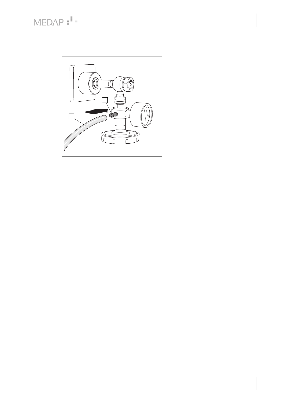
3.3.2 Operation without a hydrophobic bacterial and viral filter
1
2
Assembly of septic fluid jar with integrated
overflow protection
Attach the connection tube (1) to the tube
connector (2) of the gas-jet pump.
Attach the other end of the connection tube
to the connector on the septic fluid jar.
2
1
Initial operation
Assembly of gas-jet pump
3
Fig. 5: Connection of septic fluid jar
GA 5750 4196 GB 15
19
Page 20
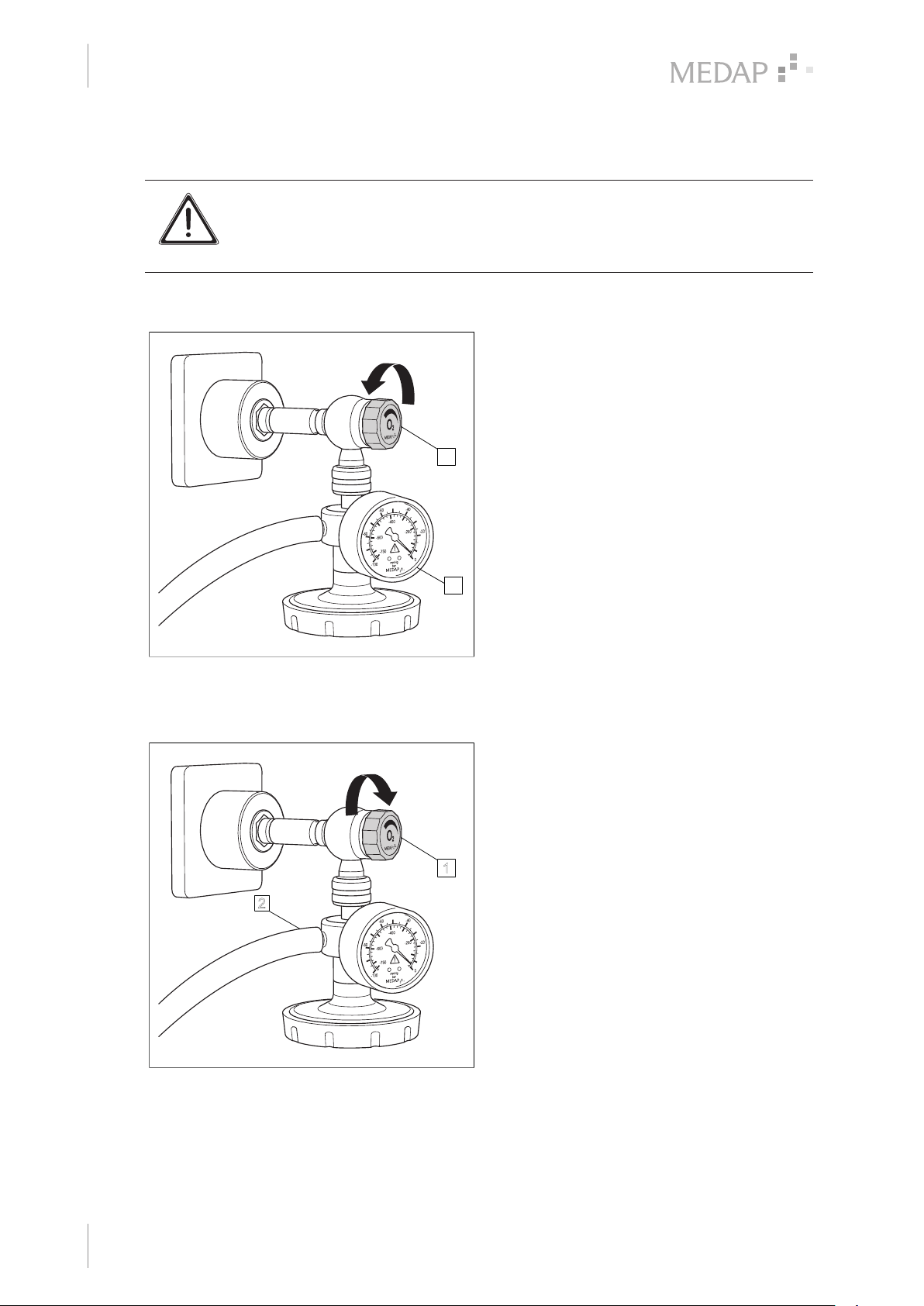
Operation
1
2
4
Gas-jet pump with gauge
4 Operation
WARNING!
Injury hazard if the catheter attaches itself to tissue!
Always use a fingertip so that the extraction process can be interrupted quickly by
releasing the fingertip.
4.1 Gas-jet pump with gauge
Open the fine regulator (1).
Read the set value on the gauge (2).
1
Fig. 6: Gas-jet pump with gauge
4.2 Disassembly of gas-jet pump
2
2
Disassembling the gas-jet pump
Close the fine regulator (1).
Detach the connection tubes (2) and the
hydrophobic bacterial and viral filter.
1
20
Fig. 7: Disassembling the gas-jet pump
GA 5750 4196 GB 15
Page 21
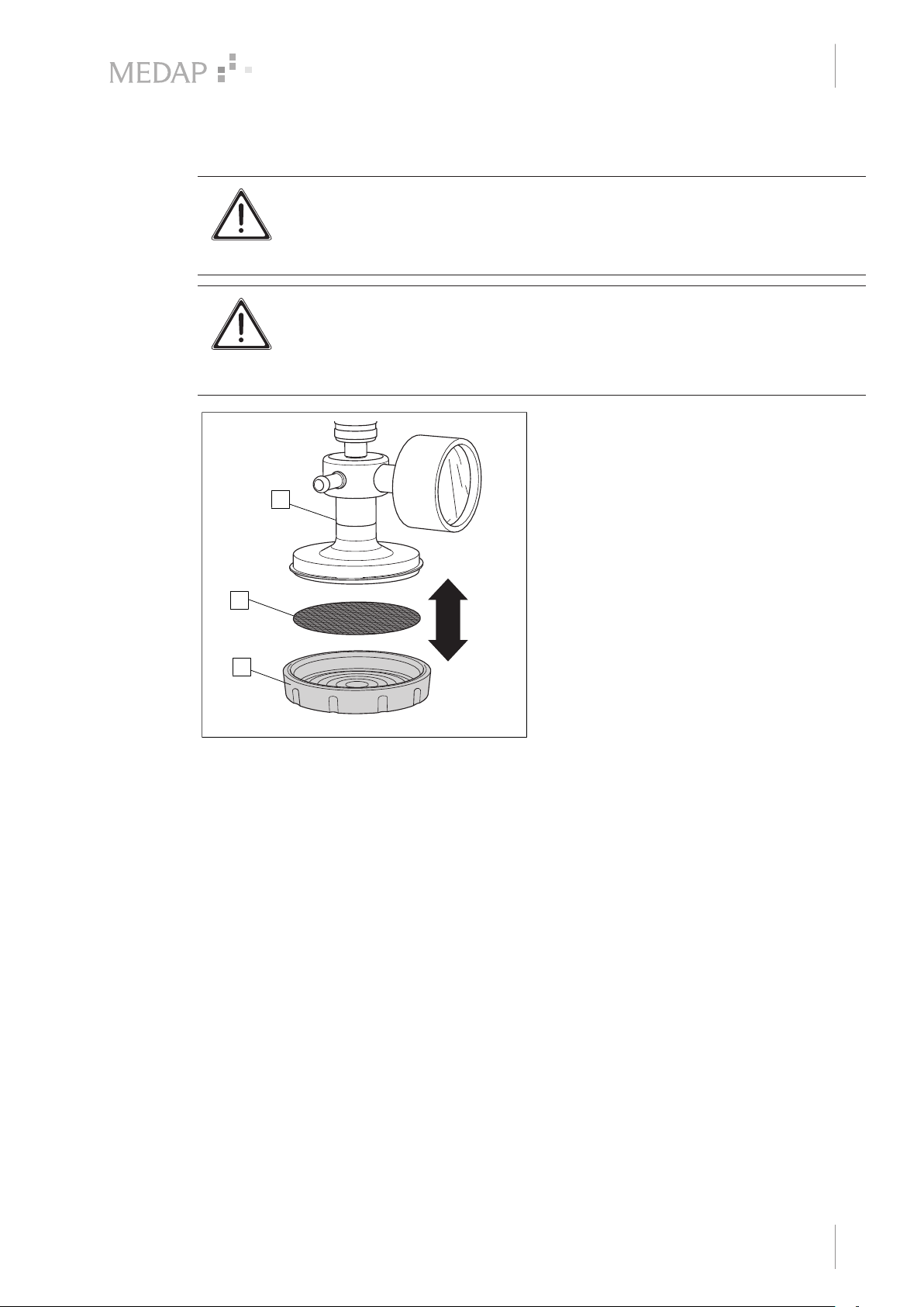
4.3 Replacing the bacterial filter paper
1
3
2
WARNING!
Hygiene!
When in use, change the bacterial filter paper every day.
Dispose of used bacterial filter papers in compliance with hygiene guidelines.
WARNING!
Risk of injury!
The suction and aspiration of laser or coagulation vapours (protein-containing
vapours) require the use of a flue gas filter which is appropriate for the specific
application.
3
Operation
Replacing the bacterial filter paper
Unscrew the bacterial filter cap (1)
anticlockwise.
Insert the bacterial filter paper (2) into the
bacterial filter cap.
The finely textured side points towards
the product (3).
Gently screw the bacterial filter cap back on
in a clockwise direction.
4
2
1
Fig. 8: Replacing the bacterial filter paper
GA 5750 4196 GB 15
21
Page 22
Cleaning and disinfection
5
General
5 Cleaning and disinfection
5.1 General
The product must be wipe or spray disinfected after every use.
DANGER!
Risk due to incorrect use of detergents and disinfectants!
It is strictly advised to observe the manufacturer’s instructions regarding how to
use the detergents and disinfectants as well as to observe the valid hospital
hygiene rules.
DANGER!
Infection hazard!
Product may be contaminated.
Always wear gloves for cleaning and disinfection.
DANGER!
Infection hazard!
Particles of grime may become encapsulated and lead to the product not reaching
the desired germ reduction after disinfection.
Before disinfection, the product must be cleaned thoroughly of contamination and
encapsulated particles of grime.
CAUTION!
Improper cleaning and disinfection can cause property damage!
Do not use the following products for cleaning and disinfection:
• Products containing alcohol (e.g. hand disinfectants)
• Halogenides (e.g. fluorides, chlorides, bromides, iodides)
• Dehalogenating compounds (e.g. fluorine, chlorine, bromine, iodine)
• Products that may scratch the surface (e.g. scouring agents, wire brushes, wire
wool)
• Standard commercial solvents (e.g. benzene, thinner)
• Water containing iron particles
• Cleaning sponges containing iron
• Products containing hydrochloric acid
Use a soft, lint-free cloth or a soft nylon brush to clean the product.
22
CAUTION!
Improper cleaning and disinfection can cause property damage!
Use only as much detergent and disinfectant as required.
CAUTION!
Improper cleaning and disinfection can cause property damage!
After each cleaning and disinfection process, carry out the functionality test.
GA 5750 4196 GB 15
Page 23
5.2 Cleaning
5.2.1 General
Cleaning and disinfection
Cleaning
NOTE
Use only all-purpose cleaners which are slightly alkaline (soap solution) and
contain surfactants and phosphates as the active cleaning agents.
In the event of heavily contaminated surfaces, use concentrated all-purpose
detergent.
CAUTION!
Improper cleaning can cause property damage!
Residues of physiological saline solutions (e.g. sodium chloride) can attack the
surfaces of the product.
Remove residues of physiological saline solutions with a cloth dipped in clean
water. Then dry the product with a dry, lint-free cloth.
5
CAUTION!
Improper cleaning can cause property damage!
Do not spray cleaning agent directly into the joints or gaps and never use a highpressure cleaning unit!
5.2.2 Cleaning procedure
Use the correct dose of all-purpose detergent with water for the degree of surface
contamination and in accordance with the instructions of the detergent manufacturer.
Thoroughly wipe off the product with a soft cloth slightly dampened in an all-purpose detergent
solution.
Ensure that the product is free from contamination and encapsulated particles of grime.
Thoroughly wipe off the product with a soft cloth dipped in clean water.
Ensure that the product is free of detergent residues.
Dry the product with a dry, absorbent and lint-free cloth.
This will help to reduce pathogen growth on the product's surface.
Wipe disinfect the product after every cleaning process.
5.3 Disinfection
5.3.1 General
NOTE
In the event that product surfaces are very dirty, carry out an additional cleaning
procedure before disinfecting.
DANGER!
Reduced performance!
Only clean the product by manual disinfection.
Ensure that no disinfectants enter the unit.
Check the functionality of the product after each disinfection.
GA 5750 4196 GB 15
23
Page 24
Cleaning and disinfection
5
Disinfection
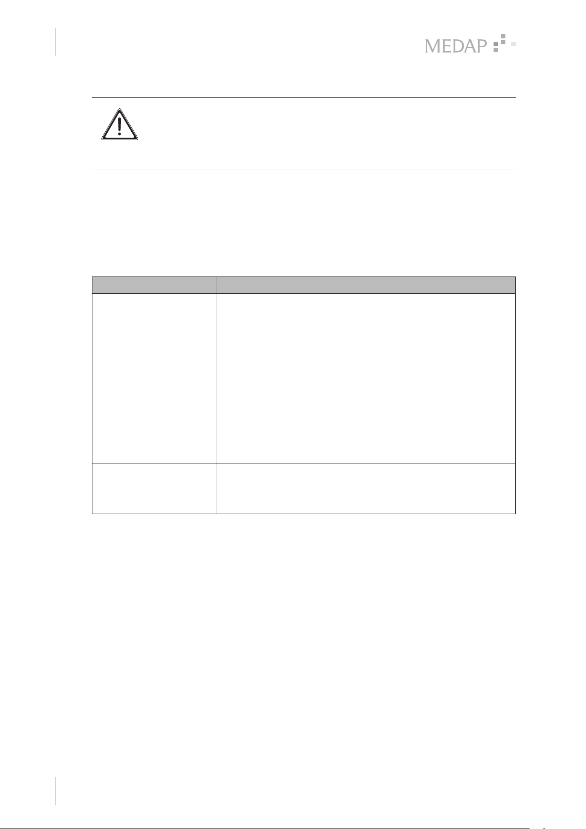
CAUTION!
Material damage due to excessive exposure times!
Exceeding the specified exposure time of the disinfectant may damage the
surfaces.
Observe the specified exposure time of the disinfectant manufacturer.
5.3.2 Suitable disinfectants
Only surface disinfectants based on the following combinations of active ingredients may be used
for disinfection:
• Aldehydes
• Quaternary ammonium compounds
• Guanidine derivatives
Ingredient group Active ingredients
Aldehydes 2-ethyl-1-hexanal, formaldehyde, glutardialdehyde, glyoxal,
o-phthaldialdehyde, succinaldehyde
Quaternary ammonium
compounds
Guanidine derivatives. Alkyl-biguanide, chlorhexidine-digluconate, cocospropylene-
Tab. 4: Active ingredients of disinfectants
5.3.3 Disinfection procedure
Wipe disinfect the product in accordance with the instructions of the disinfectant manufacturer
after every cleaning process.
Ensure that the product is free of disinfectant residue.
Perform visual and functional inspections.
Alkyl-didecyl-polyoxethyl ammonium propionate, alkyl-dimethylalkylbenzyl ammonium chloride, alkyl-dimethyl-ethyl ammonium
chloride, alkyl-dimethyl-ethylbenzyl ammonium chloride,
benzalkonium propionate, benzalkonium chloride (alkyl-dimethylbenzyl ammonium chloride, coco-dimethyl-benzyl ammonium
chloride, lauryl-dimethylbenzyl ammonium chloride, myristyldimethyl-benzyl ammonium chloride), benzethonium chloride,
benzyl-dihydroxyethyl-coco-alkyl ammonium chloride, dialkyldimethyl ammonium chloride (didecyldimethyl ammonium chloride),
didecyl-methyl-oxyethyl ammonium propionate, mecetronium-ethyl
sulfate, methyl-benzethonium chloride, n-octyl-dimethyl-benzyl
ammonium chloride
diamine guanidinium diacetate, oliogomeric biguanide,
polyhexamethylene biguanide hydrochloride (oligo-diimino imiodocarbonyl imino-hexamethylene, polyhexanide)
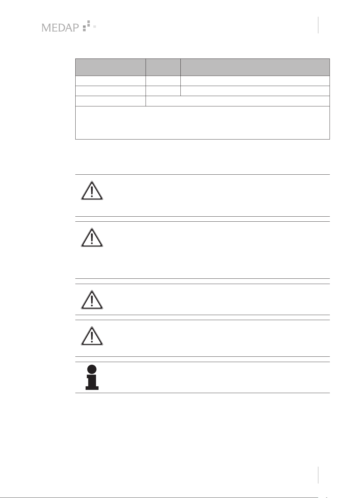
5.3.4 Disinfection procedures
Different disinfection procedures may be used for the various components, depending on the
properties of the materials. Before disinfection remove contaminations and residues from the
parts and dry well.
24
GA 5750 4196 GB 15
Page 25
Cleaning and disinfection
Product-specific safety notes
5
Components In solu-
tion
Gas-jet pump X
Bacterial filter cap X
Bacterial filter paper Disposable product. When in use, must be replaced daily.
1
After exposure (as prescribed in the manufacturer's instructions), rinse components thoroughly
with water and dry them afterwards.
2
After exposure (as prescribed in the manufacturer's instructions), remove disinfectant residues
from the components using a moist cloth and dry them afterwards.
Tab. 5: Disinfection procedures
5.4 Product-specific safety notes
DANGER!
Health hazard!
The product may not be disassembled for cleaning or disinfection. During cleaning
and disinfection, ensure that no cleaning agent, disinfectant or other contamination
is able to enter the product.
DANGER!
Risk to patient!
Oversuction of products results in them no longer being functional. There is
considerable risk to the patient if the tapping unit is not cleaned properly after being
exposed to oversuction, as safety equipment could be clogged.
After oversuction, products must be dismantled and cleaned thoroughly by
authorised service staff.
1
Wiping
2
CAUTION!
Property damage due to sterilisation!
Do not sterilise the product.
CAUTION!
Property damage!
Using non-colour-fast surgical drapes can cause discolouration of surfaces.
Only use colour-fast surgical drapes.
NOTE
For cleaning and disinfection, disconnect the connection tube with the NIST screw
connection from the tapping unit.
GA 5750 4196 GB 15
25
Page 26
Maintenance
6
General
6 Maintenance
6.1 General
Maintenance, repairs and periodic tests may only be carried out by persons who have the
appropriate technical knowledge and are familiar with the product. To carry out these measures,
the person must have the necessary test devices and original spare parts.
ATMOS recommends: work should be carried out by an authorised ATMOS service partner. This
ensures that repairs and testing are carried out professionally, original spare parts are used and
warranty claims remain unaffected.
DANGER!
Defective device!
Using incorrect spare parts or accessories can cause injuries or equipment failure.
Only use original accessories or spare parts.
DANGER!
Health hazard!
The product is used in the treatment of patients. The product or some of its
components may be contaminated.
Clean and disinfect the product before maintenance and repair. Repair work may
be performed by personnel authorised by ATMOS.
6.2 Periodic tests
Observe the country-specific requirements regarding periodic tests.
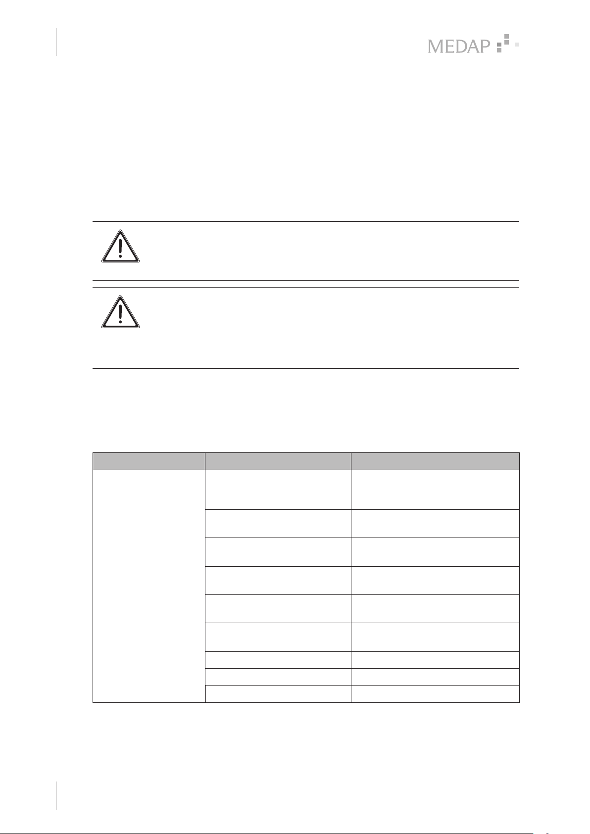
6.3 Malfunctions and troubleshooting
Defect Source of malfunction Corrective actions
• No or low vacuum
• No or reduced displacement
Oxygen gas-jet pump not
connected
Connection tube not connected
to the oxygen gas-jet pump
Connection tube too long Shorten connection tube to a
Connection tube collapses Use special connection tube
Full septic fluid jar, overflow
protection system closed
Oversuction of hydrophobic
bacterial and viral filter
Seal damaged Replace seal
Suction system is leaking Check suction system
Attach oxygen gas-jet pump in
accordance with the operating
instructions
Connect connection tube according
to operating instructions
maximum length of 50 cm
(vacuum proof up to –95kPa)
Empty/replace septic fluid jar,
replace overflow protection system
Replace hydrophobic bacterial and
viral filter
26
Fine regulator not open Open the fine regulator
GA 5750 4196 GB 15
Page 27

Maintenance
Defect Source of malfunction Corrective actions
Central supply system failure Contact Technical Service
Fine regulator defective
Adjusting screw on fine
regulator defective
Repairs
6
Device oversuction No overflow protection device
The oxygen gas-jet
pump is leaking
Tab. 6: Corrective actions
6.4 Repairs
The following may require repairs by the manufacturer or an authorised service partner:
• Liquid has penetrated the device.
• The performance has significantly decreased.
• Inexplicable notifications appear.
• Abnormal noises occur.
• Functional faults cannot be rectified according to the measures in chapter Malfunctions and
troubleshooting [ page 26].
If defects are detected, the product may not be used any longer.
Make a note of the deficiencies and the REF number on the data plate and inform your ATMOS
representative.
Observe the information in chapter Sending in the device [ page 27].
Contact Technical Service
used
Seal is missing or defective Have oxygen gas-jet pump inspected
There is a leak in the housing
Accessories are not tightened Check fit of accessories
6.5 Service hotline
+49 7653 689-0
6.6 Sending in the device
Remove and properly dispose of consumables.
Clean and disinfect the product and accessories according to the operating instructions.
Place used accessories with the product.
Fill in the form QD 434 ‘Delivery complaint / return shipment’ and the respective
decontamination certificate.
This form is enclosed with each delivery and can be found at www.atmosmed.com.
The device must be well padded and packed in suitable packaging.
Place the form QD 434 ‘Delivery complaint / return shipment’ and the respective
decontamination certificate in an envelope.
Affix the envelope to the outside of the package.
Send the product to ATMOS or to your dealer.
GA 5750 4196 GB 15
27
Page 28
Technical specifications
7
General
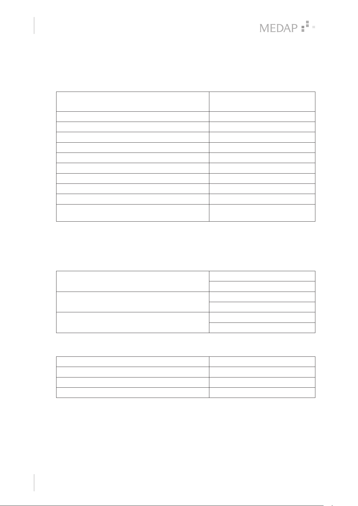
7 Technical specifications
7.1 General
Classification as per Annex IX of
Directive 93/42/EEC
Rated operating pressure 500 kPa* ± 10%
Flow rate** (high flow) 32 l/min
Flow rate** (low flow) 12 l/min
Connection thread O2 G 3/8"
Connection thread AIR M 18x1
Maximum vacuum −80 kPa*
Accuracy class of gauge 1.6
Excess pressure equipment < 1 kPa
Pore width of outlet filter 0.3 μm
Performance class HF/HV (High Flow / High Vac) LF/HV
* 100 kPa = 1 bar = 1000 mbar = 750 mmHg
** in accordance with EN 10079-3. Depending on the design of the gas supply system, the actual
performance of the tapping fittings may be reduced.
7.2 Ambient conditions
Class IIa
(Low Flow / High Vac)
Temperature −15 °C to +50 °C (shipping)
Relative humidity less than 100% (shipping)
Atmospheric pressure 700 hPa to 1060 hPa (shipping)
7.3 Dimensions and weight
Dimensions without gauge (L x W x H) 90 x 100 x 80 mm
Dimensions with gauge (L x W x H) 90 x 100 x 110 mm
Weight without gauge 325 g
Weight with gauge 450 g
+10 °C to +40 °C (operation)
30% to 75% (operation)
700 hPa to 1060 hPa (operation)
28
GA 5750 4196 GB 15
Page 29

8 Accessories
8.1 Accessories
The following accessories are not part of the scope of delivery and must be ordered separately:
FINA fine regulator O2 5752 3705
FINA fine regulator AIR 5752 3708 /
Tab. 7: Accessories
8.2 Consumables
Hydrophobic bacterial and viral filter (disposable) 5750 0630
Vacuum connection tube 6 x 12 mm 5750 5467
Accessories
Accessories
5752 3709 /
5752 3710
8
Fingertip 000.0347.0
Bacterial filter paper 5750 5045
Tab. 8: Consumables
GA 5750 4196 GB 15
29
Page 30

Notes
Page 31

Notes
Page 32

Manufacturer:
ATMOS
MedizinTechnik GmbH & Co. KG
Ludwig-Kegel-Str. 16
79853 Lenzkirch
GERMANY
Telephone: +49 7653 689-0
www.atmosmed.com
 Loading...