

Page 1
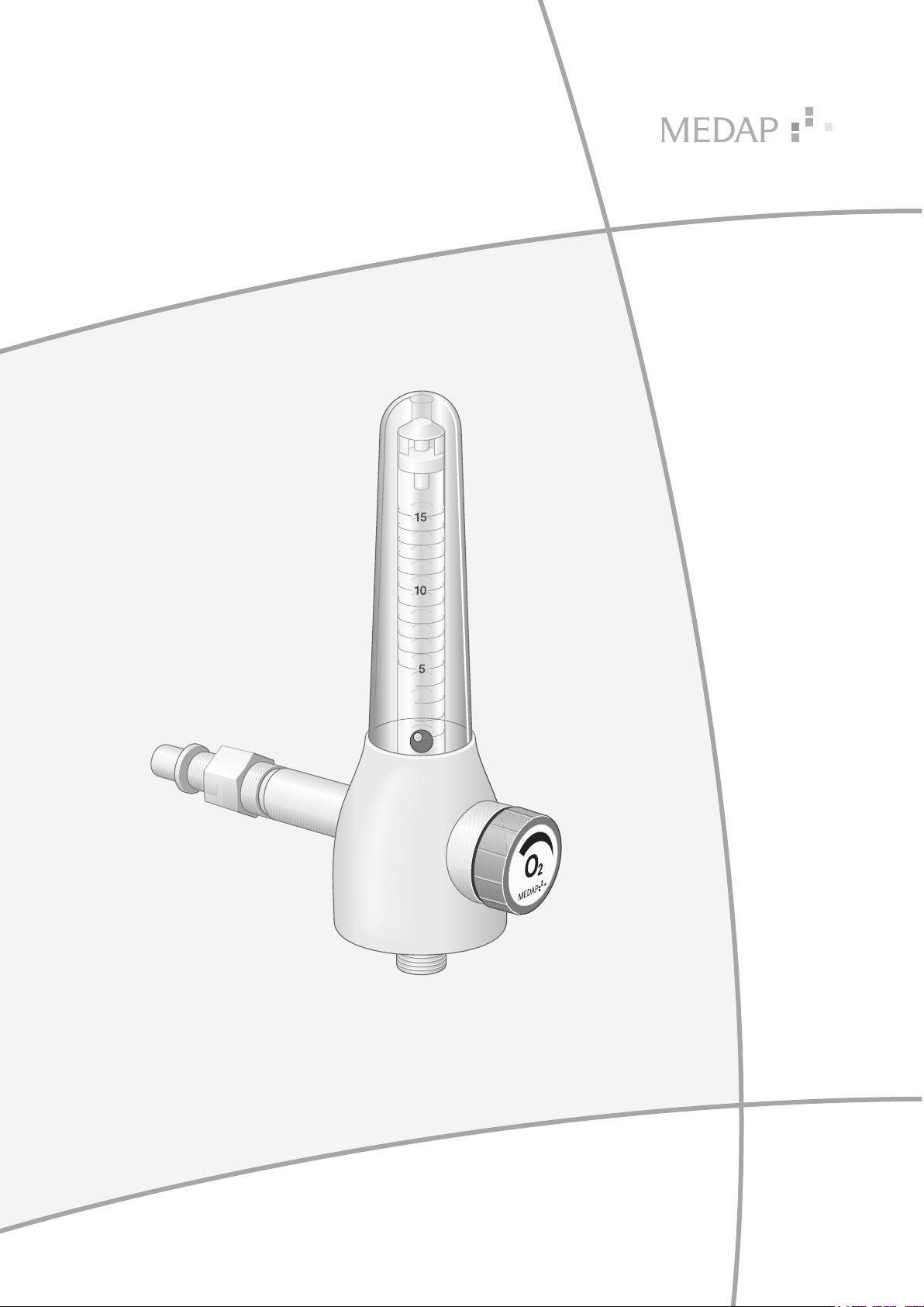
OPERATING INSTRUCTIONS
FLOWMETER
MEDAP-FINA FLOW
MEDAP-FINA DFLOW
GA 5752 2804 GB 18
Page 2

Subject to technical modification!
4
Illustrations and technical specifications may vary slightly from those in these operating
instructions as a result of ongoing product development.
V18 2020-07
2
GA 5752 2804 GB 18
Page 3

Table of contents
Table of contents
1 Introduction ..............................................................................................................................................5
1.1 Foreword .................................................................................................................................................... 5
1.2 How to use these operating instructions .................................................................................................... 5
1.2.1 Abbreviations ...............................................................................................................................5
1.2.2 Symbols .......................................................................................................................................5
1.2.2.1 Cross-references ....................................................................................................... 5
1.2.2.2 Actions and responses .............................................................................................. 5
1.2.3 Definitions ....................................................................................................................................6
1.2.3.1 Design of safety notes ............................................................................................... 6
1.2.3.2 Structure of notes ...................................................................................................... 6
1.2.4 Symbols used ..............................................................................................................................6
1.3 Disposal ......................................................................................................................................................8
1.3.1 Packaging ....................................................................................................................................8
1.3.2 ATMOS products .......................................................................................................................... 8
1.4 Overview of FINA FLOW flowmeter ...........................................................................................................9
1.5 Basic requirements ...................................................................................................................................10
1.5.1 Use in accordance with the intended purpose ........................................................................... 10
1.5.2 Applicable standards / directives ............................................................................................... 10
1.5.3 Intended purpose ....................................................................................................................... 10
1.5.4 Versions of FINA FLOW / DFLOW flowmeter ............................................................................ 11
1.5.5 Possible applications .................................................................................................................12
1.5.6 Interface description ...................................................................................................................12
1.5.6.1 Approved interface for compressed gas supply ...................................................... 12
1.5.6.2 Flowmeter outlet ...................................................................................................... 12
1.5.6.3 Connection tube ...................................................................................................... 12
1.5.6.4 Tube adapter for AIR and O2 ................................................................................... 13
2 Safety notes ............................................................................................................................................14
2.1 General safety notes ................................................................................................................................ 14
2.2 Product safety notes .................................................................................................................................14
3 Initial operation .......................................................................................................................................16
3.1 Product testing .........................................................................................................................................16
3.2 Connection to the terminal unit.................................................................................................................16
3.2.1 General ......................................................................................................................................16
3.2.2 Version A ....................................................................................................................................17
3.2.3 Version B ....................................................................................................................................17
3.3 Mounting accessories ...............................................................................................................................17
3.3.1 General ......................................................................................................................................17
3.3.2 Connection of the bubble humidifier (REF 5752 5315) .............................................................. 18
3.3.3 Connection of disposable humidifiers from other manufacturers ............................................... 18
GA 5752 2804 GB 18
3
Page 4

Table of contents
4 Operation ................................................................................................................................................19
4.1 Function test ............................................................................................................................................. 19
4.2 Setting the flow for treatment ...................................................................................................................19
5 Taking the unit out of operation ............................................................................................................ 21
6 Cleaning and disinfection ......................................................................................................................22
6.1 General .....................................................................................................................................................22
6.2 Cleaning ................................................................................................................................................... 23
6.2.1 General ......................................................................................................................................23
6.2.2 Cleaning procedure ....................................................................................................................23
6.3 Disinfection ............................................................................................................................................... 24
6.3.1 General ......................................................................................................................................24
6.3.2 Suitable disinfectants ................................................................................................................. 24
6.3.3 Disinfection procedure ...............................................................................................................25
6.4 Special safety notes ................................................................................................................................. 25
7 Maintenance ............................................................................................................................................26
7.1 General .....................................................................................................................................................26
7.2 Periodic tests ............................................................................................................................................ 26
7.3 Malfunctions and troubleshooting.............................................................................................................26
7.4 Repairs ..................................................................................................................................................... 27
7.5 Service hotline .......................................................................................................................................... 27
7.6 Type plate position ...................................................................................................................................27
7.7 Sending in the device ............................................................................................................................... 27
8 Technical specifications ........................................................................................................................ 29
8.1 General .....................................................................................................................................................29
8.2 Ambient conditions ................................................................................................................................... 29
8.3 FINA FLOW O 15 / A 15 ...........................................................................................................................29
8.4 FINA DFLOW O 15 ...................................................................................................................................29
9 Approved accessories ...........................................................................................................................30
9.1 Accessories .............................................................................................................................................. 30
9.2 Scope of delivery ...................................................................................................................................... 30
4
GA 5752 2804 GB 18
Page 5

1 Introduction
1.1 Foreword
Your facility has selected the leading-edge medical technology made by ATMOS. We sincerely
appreciate the trust you have placed in us.
1.2 How to use these operating instructions
These operating instructions are provided to familiarise you with the features of this ATMOS
product. They are subdivided into several chapters.
Please note:
• Please read these operating instructions carefully and completely before using the product for
the first time.
• Always proceed in accordance with the information contained herein.
• Store these operating instructions in a location near the product.
1.2.1 Abbreviations
Introduction
Foreword
1
EEC European Economic Community
VDE Verband der Elektrotechnik Elektronik Informationstechnik (Association for
Electrical, Electronic & Information Technology)
1.2.2 Symbols
1.2.2.1 Cross-references
References to other pages in these operating instructions are identified with a double arrow
symbol ‘’.
1.2.2.2 Actions and responses
The ‘’ symbol identifies an action taken by the user, while the ‘’ symbol identifies the reaction
that this will induce in the system.
Example:
Turn on the light switch.
Lamp lights up.
GA 5752 2804 GB 18
5
Page 6
Introduction
4
1
How to use these operating instructions
1.2.3 Definitions
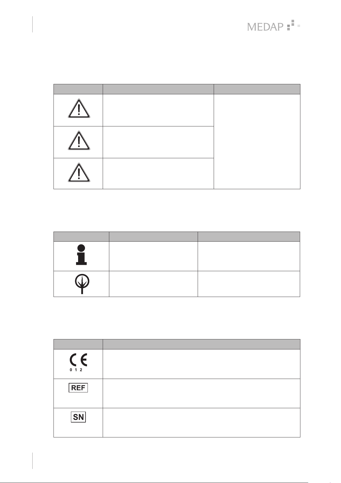
1.2.3.1 Design of safety notes
Pictogram Descriptor Text
DANGER!
Indicates a direct and immediate risk to
persons which may be fatal or result in
most serious injury.
WARNING!
Indicates a potential risk to persons or
property which may result in health hazard
or grave property damage.
CAUTION!
Indicates a potential risk to property which
may result in property damage.
The text for the safety note
describes the type of risk and
how to avert it.
Tab. 1: Design of safety notes
1.2.3.2 Structure of notes
Notes not referring to personal injury or property damage are structured as follows:
Pictogram Descriptor Reference to
Tab. 2: Structure of notes
1.2.4 Symbols used
Symbols are attached to products, type plates and packaging.
Symbols Identification
NOTE Supplementary assistance or further
useful information without potential
injury to persons or property damage
is described in the text of the note.
ENVIRONMENT Information regarding proper disposal.
Labelling for products which were developed and are marketed in
compliance with the Medical Devices Directive 93/42/EEC. Class Is, Im, IIa,
IIb and III products are also marked with the identifying number of the
Notified Body.
Labelling in compliance with the ISO 15223-1 standard.
Symbol for ‘Product number’.
Labelling in compliance with the ISO 15223-1 standard.
Symbol for ‘Serial number’.
6
GA 5752 2804 GB 18
Page 7
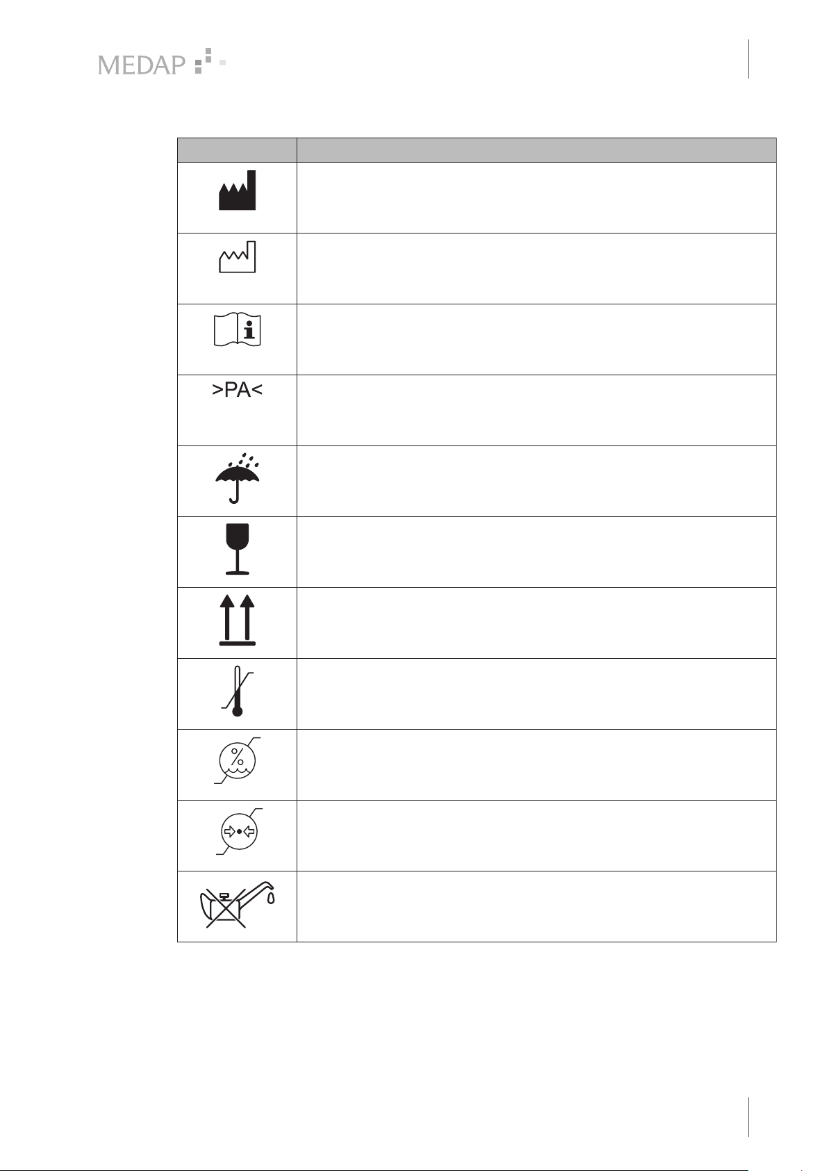
Symbols Identification
Labelling in compliance with the ISO 15223-1 standard.
Symbol for ‘Name and address of the manufacturer as well as date of
manufacture’.
Labelling in compliance with the ISO 15223-1 standard.
Symbol for ‘Date of manufacture’.
Labelling in compliance with the ISO 15223-1 standard.
Symbol for ‘Follow operating instructions’.
Material designation for the plastic PA (polyamide).
Introduction
How to use these operating instructions
1
Packaging label.
Symbol for ‘Keep dry’.
Packaging label.
Symbol for ‘Fragile! Handle with care’.
Packaging label.
Symbol for ‘Top’.
Labelling in compliance with the ISO 15223-1 standard.
Symbol for ‘Temperature limitations’.
Labelling in compliance with the ISO 15223-1 standard.
Symbol for ‘Relative humidity’.
Labelling in compliance with the ISO 15223-1 standard.
Symbol for ‘Atmospheric pressure’.
Tab. 3: Symbols
Labelling on type plate.
Symbol for ‘Oil- and fat-free’.
GA 5752 2804 GB 18
7
Page 8

Introduction
1
Disposal
1.3 Disposal
WARNING!
Infection hazard!
The product or some of its components may be contaminated after use.
Clean and disinfect the product before disposal.
1.3.1 Packaging
The packaging is made of materials compatible with the environment. ATMOS will dispose of the
packaging materials upon request.
1.3.2 ATMOS products
ATMOS will take back used products or those which are no longer in service.
Please contact your ATMOS representative for more detailed information.
8
GA 5752 2804 GB 18
Page 9
1.4 Overview of FINA FLOW flowmeter
Introduction
Overview of FINA FLOW flowmeter
9
1
1
2
3
6
4
5
8
7
11
10
12
13
14
15
16
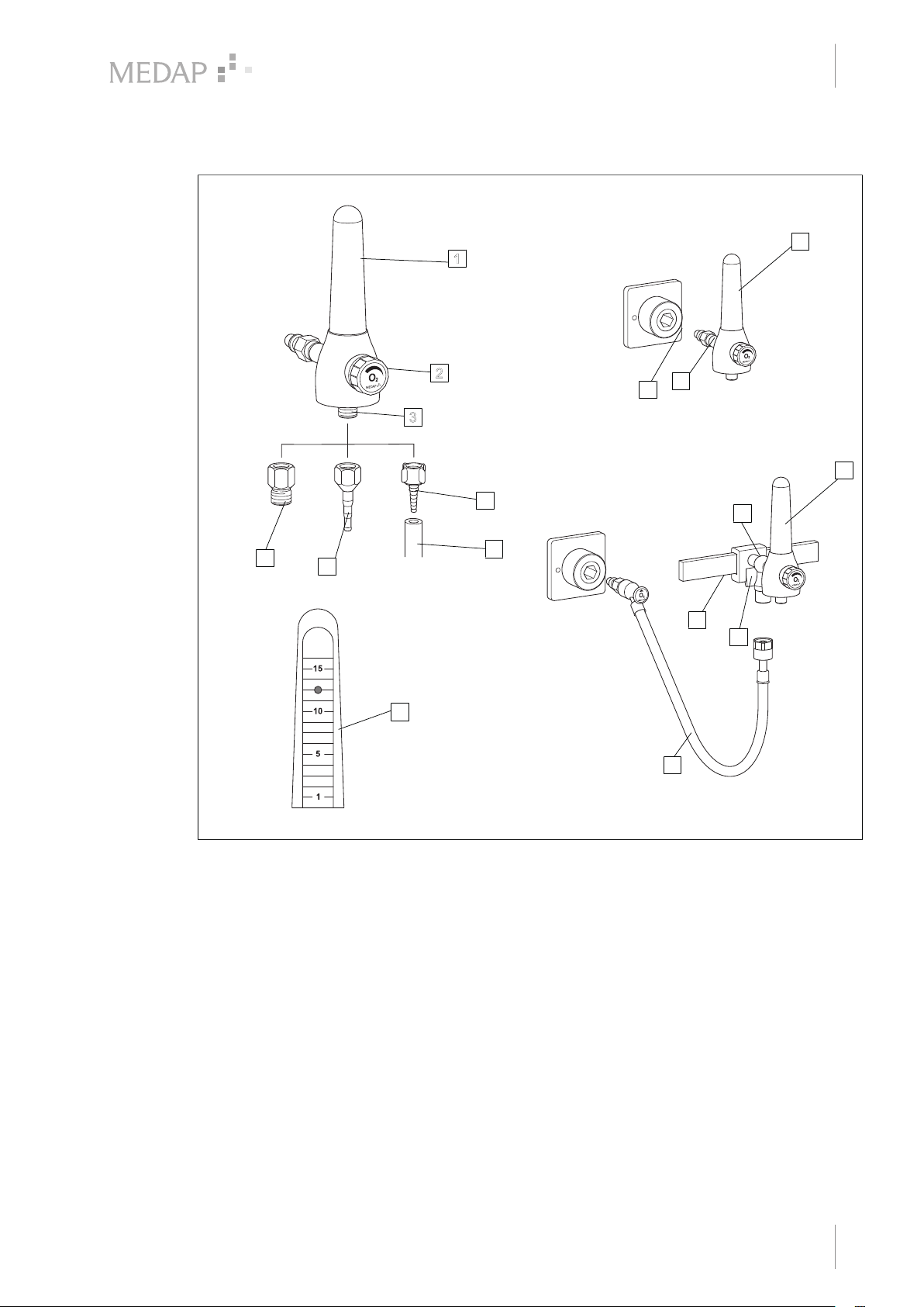
Fig. 1: Overview of FINA FLOW flowmeter
1 Flowmeter viewing tube 9 Version A
2 Control valve
3 Flowmeter outlet (UNF 9/16") 10 Plug
4 Adapter for humidifier (UNF 9/16” – G 3/8") 11 Terminal unit
5 Tube adapter 4 mm, 6 mm, 8 mm (UNF 9/16") 12 Version B
6 Tube adapter, plastic, 4 mm, 6 mm, 8 mm
(UNF 9/16") 13 Rail clamp
7 Connection tube 14 Equipment rail
8 Measuring scale 15 Locking lever
Tapping unit with integrated gas pin
Tapping unit with rail clamp and NIST connection
16 Connection tube
GA 5752 2804 GB 18
9
Page 10

Introduction
1
Basic requirements
1.5 Basic requirements
1.5.1 Use in accordance with the intended purpose
Product
As per Annex IX to the Medical Devices Directive 93/42/EEC, this product belongs to class IIa.
In accordance with this directive, the product may only be used by persons who have been
instructed how to use this product by an authorised person.
This product is to be used exclusively for human medicine.
When employed in commercial or business use, this product must be entered in the inventory.
Accessories
Accessories or combinations of accessories may be utilised only as and when indicated in these
operating instructions.
Other accessories, combinations of accessories and consumable items may be used only if they
have a valid certification, are intended expressly for the particular use and will not adversely
affect performance, the prescribed ambient conditions or safety requirements.
1.5.2 Applicable standards / directives
The product satisfies the basic requirements set forth in Annex I to Council Directive 93/42/EEC
concerning medical devices (Medical Devices Directive) as well as the applicable national
(German) codes and the Medical Devices Act (MPG) in Germany. This has also been
demonstrated through the application of the corresponding standards which have been
harmonised with Directive 93/42/EEC.
1.5.3 Intended purpose
Name: FINA FLOW
FINA DFLOW
Main function: Designed for measuring the flow and determining the precise
dosage for the supply of oxygen and compressed air. In conjunction
with a hand-held nebuliser, the FINA FLOW is used to provide
metered administration of medication aerosols.
Medical indications /
application:
Specification of the main
function:
Inhalation and insufflation of oxygen within the scope of oxygen
enrichment via an inhalation mask or nose latch for patients who
can breathe independently.
Together with a hand-held nebuliser, administration of water-soluble
medications via an inhalation mask.
Supply of oxygen or compressed air. For oxygen / compressed air
supply, FINA FLOW is connected to a terminal unit for oxygen /
compressed air of a central medical gas supply system with a
pressure of 500 kPa ± 10%. For humidification of oxygen from the
central gas supply system, a humidifier may additionally be
connected. Supply of oxygen to the patient takes place via
connection tubes and an inhalation mask or a nose latch. The
administration of medication aerosols via compressed air takes
place via connection tubes to a hand-held nebuliser. The patient
presses the inhalation mask of the hand-held nebuliser onto the
mouth and nose.
10
User profile: Doctor, medically trained staff
GA 5752 2804 GB 18
Page 11

Introduction
Basic requirements
Patient groups: Patients of all ages
Application organ: Lung
Application time: For continuous operation; in practice, short-term use on the patient
(< 30 days)
Application site: The application site is the clinical environment and doctor’s
practices which have a central oxygen / compressed air system.
The application of the product may only be performed by medically
trained and instructed staff.
Contraindications: The FINA FLOW may not be used for the following purposes:
• Outside the medical sector
• In MR areas
• In the home care sector
• Being operated directly by the patient
• For exclusive respiration
• With central gas supply systems having supply pressures other
than 500 kPa ± 10%
• When applying oxygen in its function as a medication, it is absolutely necessary to measure the flow rate.
1
The product is: Not active
Sterility: Not a sterile product
Single-use product /
reprocessing:
1.5.4 Versions of FINA FLOW / DFLOW flowmeter
The connection of the tapping unit to oxygen or compressed air depends on the model being
used:
Version A: Tapping unit with integrated gas pin
• FINA FLOW is fitted directly to the terminal unit.
Version B: Tapping unit with rail clamp and NIST connection
• FINA FLOW is designed for mounting onto a 25 x 10 mm equipment rail and is supplied via a
NIST connection with oxygen or compressed air from a terminal unit connected using a connection tube with gas probe.
Products and accessories are only permitted with the ISO colour coding. In Germany, Austria and
Switzerland, products with neutral colour coding are also permitted.
NOTE
The products are supplied with ISO coding. The scope of delivery includes a label
for neutral colour coding.
The device and parts of the accessories are reusable. For
information on reprocessing, cleaning and disinfection, please see
the operating instructions.
GA 5752 2804 GB 18
11
Page 12

Introduction
1
Basic requirements
The product is available in the following versions:
• FINA FLOW O 15 Wall DIN (REF 5752 3681)
• FINA FLOW O 15 NIST connection, equipment rail (REF 5752 3682)
• FINA FLOW O 15 Wall MEDAP (REF 5752 3680)
• FINA DFLOW O 15 Wall MEDAP (REF 5752 3688)
• FINA DFLOW O 15 Wall DIN (REF 5752 3689)
• FINA DFLOW O 15 NIST connection, equipment rail (REF 5752 3690)
• FINA FLOW A 15 Wall MEDAP (REF 5752 3696)
• FINA FLOW A 15 Wall DIN (REF 5752 3697)
• FINA FLOW A 15 NIST connection, equipment rail (REF 5752 3698)
1.5.5 Possible applications
The following usage options are made possible by connecting products or accessories which are
contained in the list of accessories or which satisfy the specifications of the interface description.
• A metal tube adapter (REF 5752 2746) or plastic one (REF 5752 5316) can be used to connect suitable connection tubes with inner diameters of 4 mm, 6 mm and 8 mm to the flowmeter.
• With the bubble humidifier (REF 5752 5315) for humidifying oxygen. The bubble humidifier is
intended for inhalation. The bubble humidifier is connected directly to the flowmeter.
• Sterile water systems / disposable humidifiers with a UNF 9/16" input may be connected
directly.
1.5.6 Interface description
All devices and accessories which are combined with the tapping unit must be listed in the
accessories list or meet the specifications of the interface description. Configuration of the overall
system as well as functional testing are subject to the overall responsibility of the medical staff.
Functionality and suitability of the connected accessory for each intended application must be
checked by the operator before every use. This includes the functionality of the connector
components, airtightness and suitability regarding material properties, working pressure and flow
rate.
1.5.6.1 Approved interface for compressed gas supply
In order to supply compressed gas, the tapping unit is connected to the central medical gas
supply system (CGSS) with a pressure of 500 kPa ± 10%.
The pressure in the supply line must be indicated and in the event of improper functioning must
be limited to 1000 kPa by an integrated pressure relief valve.
1.5.6.2 Flowmeter outlet
The internal thread on the accessory must match the external thread on the flowmeter
(UNF 9/16" 18 gear). Ensure that the connection between the flowmeter and the accessory is
leak-free.
1.5.6.3 Connection tube
The connection tube with an inner diameter of 4, 6 or 8 mm is connected with the tube adapter.
The connection tube may not collapse or must be pressure-resistant and must comply with the
hygiene standard of the hospital. The inner diameter of the connection tube must match the outer
diameter of the tube adapter.
12
GA 5752 2804 GB 18
Page 13

1.5.6.4 Tube adapter for AIR and O2
The tube adapter is used to connect the tapping unit and the connection tube. The internal thread
of the tube adapter must match the external thread of the tube connector of the flowmeter outlet
(UNF 9/16").
Introduction
Basic requirements
1
GA 5752 2804 GB 18
13
Page 14
Safety notes
2
General safety notes
2 Safety notes
2.1 General safety notes
DANGER!
Incorrect use can result in fatalities!
Instructions for using components made by other manufacturers are not part of
these operating instructions.
Ensure that the manufacturer's instructions are followed.
DANGER!
Observe hygiene guidelines!
Contaminated components may be hazardous to the patient's health.
Prepare the product according to the hygiene guidelines before using it for the first
time. Clean and disinfect the product.
DANGER!
Fire/explosion hazard!
Air, oxygen and oxygen compounds react explosively with oils, greases and
lubricants. Fire and explosion hazard due to compressed gases.
Always keep the product free of oils, greases and lubricants.
DANGER!
Fire hazard!
Fire hazard as a result of escaping oxygen.
Never smoke near equipment which carries oxygen and avoid using open fires or
glowing objects. Check the connector for leaks and tight fit when mounting
accessories.
DANGER!
Defective product!
Using incorrect spare parts and accessories can cause injuries or equipment
failure.
Only use original accessories or spare parts.
WARNING!
Risk of injury!
Hazard resulting from incorrect handling.
Follow the operating instructions for all accessories.
2.2 Product safety notes
CAUTION!
Malfunction!
Ensure that the connection between the product and the accessory is leak-free.
14
GA 5752 2804 GB 18
Page 15
Safety notes
Product safety notes
CAUTION!
Property damage!
Exposure to UV rays can cause material fatigue. The stability would no longer be
ensured.
Do not expose the product to strong UV light.
CAUTION!
Observe ambient conditions!
The precision, operation, mechanical stability and tightness of the product cannot
be guaranteed if the ambient temperature range is undercut or exceeded.
WARNING!
Impacts!
Impacts may cause damage to sensitive, precision mechanical components.
Do not expose the product to impacts.
2
WARNING!
Non-permissible load!
If the permissible load is exceeded, leakages may occur at the connection between
the terminal unit and the gas probe.
In accordance with DIN EN ISO 9170-1, the overall weight of the product and
accessories may not exceed 2 kg.
GA 5752 2804 GB 18
15
Page 16
Initial operation
3
Product testing
3 Initial operation
3.1 Product testing
DANGER!
Imprecise display in the event of deviations in system pressure!
If the system pressure of 500 kPa ± 10% is undercut or exceeded, it will no longer
be possible to accurately display the measured values of the flowmeter.
DANGER!
Fluctuations in flow rate!
Flow accuracy may be influenced by the following factors:
• Fluctuations in the supply pressure (terminal unit)
• Fluctuations in the back pressure (accessories)
• Fluctuations in the ambient temperature
DANGER!
Product testing!
Only product parts which are in perfect condition can ensure proper functioning of
the product. The product parts will thus have to be carefully inspected before
mounting.
WARNING!
Measurement accuracy!
The product may only be operated in a vertical position.
Pay special attention to the firm fit of the flowmeter viewing tube and to any possible cracks in
the flowmeter viewing tube. Do not use the product if there are any signs of cracks.
Check whether the connection tubes are undamaged.
Check whether the product has been properly cleaned and that there are no residues or
soiling.
Do not use damaged components.
3.2 Connection to the terminal unit
3.2.1 General
NOTE
Please refer to the manufacturer’s instructions for the particular terminal unit for
information on connecting the gas probe to the terminal unit.
16
GA 5752 2804 GB 18
Page 17
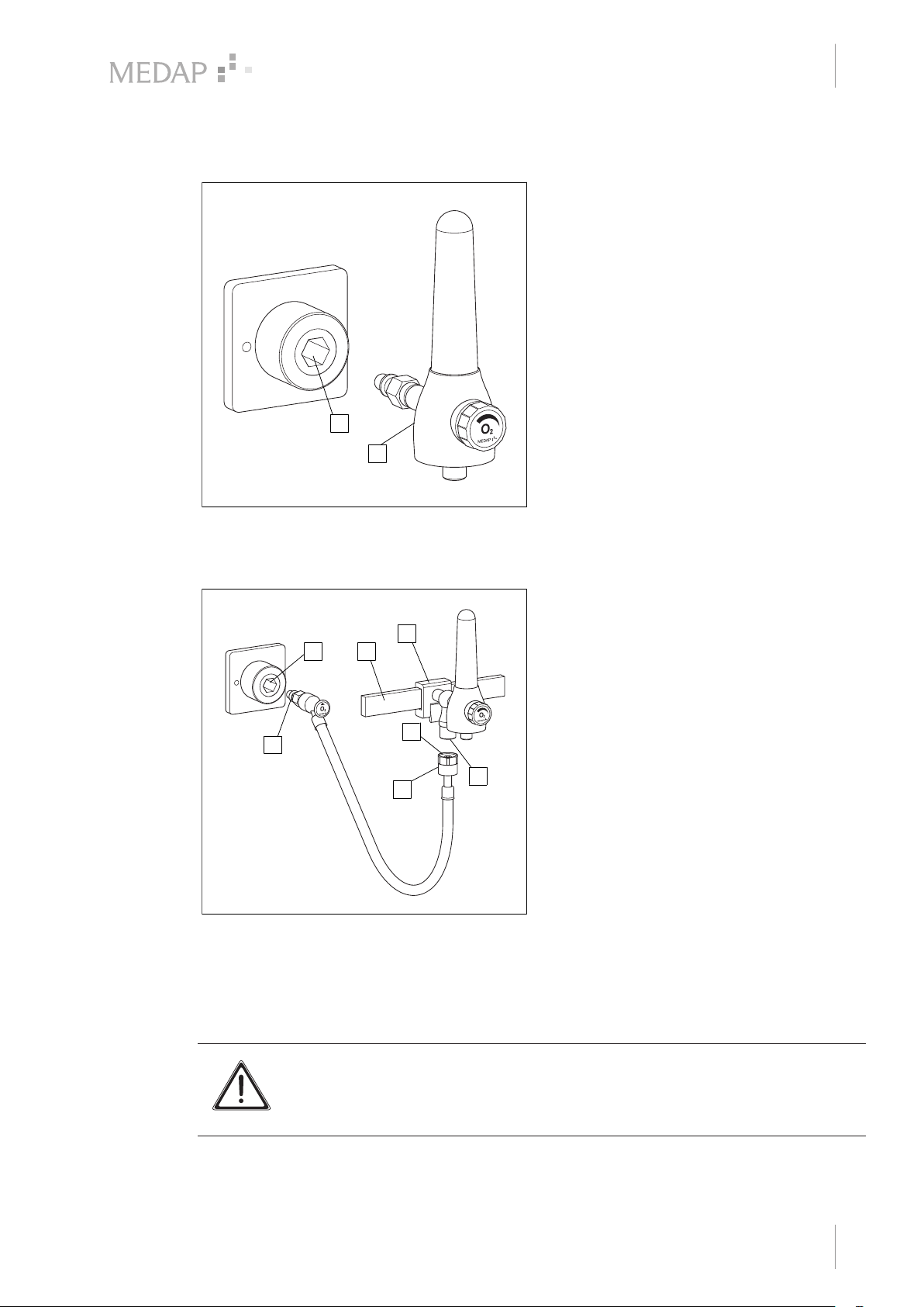
3.2.2 Version A
1
2
2
1
4
6
5
7
3
Initial operation
Mounting accessories
Tapping unit with integrated gas pin
The tapping unit (1) is plugged directly into
the terminal unit (2).
2
1
3
Fig. 2: Version A
3.2.3 Version B
Fig. 3: Version B
Tapping units with rail clamp and NIST
connection
1
7
6
2
3
4
5
With the upper edge of the guide groove at
the front, position the rail clamp (1) at a
slight angle on the equipment rail (2) and
then press it against the equipment rail and
allow it to click into place.
Make sure that the rail clamp is correctly
secured and that the tapping unit is in a
stable position on the equipment rail.
Insert the NIST nipple (3) of the connection
tube into the NIST connection (4) of the
tapping unit and tighten down the NIST
screw connection (5) by hand.
Plug the gas probe (6) into the terminal unit
(7).
3.3 Mounting accessories
3.3.1 General
WARNING!
Tensile forces!
The connected accessories must not exert any mechanical forces which could
adversely affect the secure fit of the product.
GA 5752 2804 GB 18
17
Page 18
Initial operation
1
2
3
Mounting accessories
WARNING!
Tensile forces!
Hold the basic unit with one hand when installing or removing accessories in order
to compensate for the tensile forces which are created.
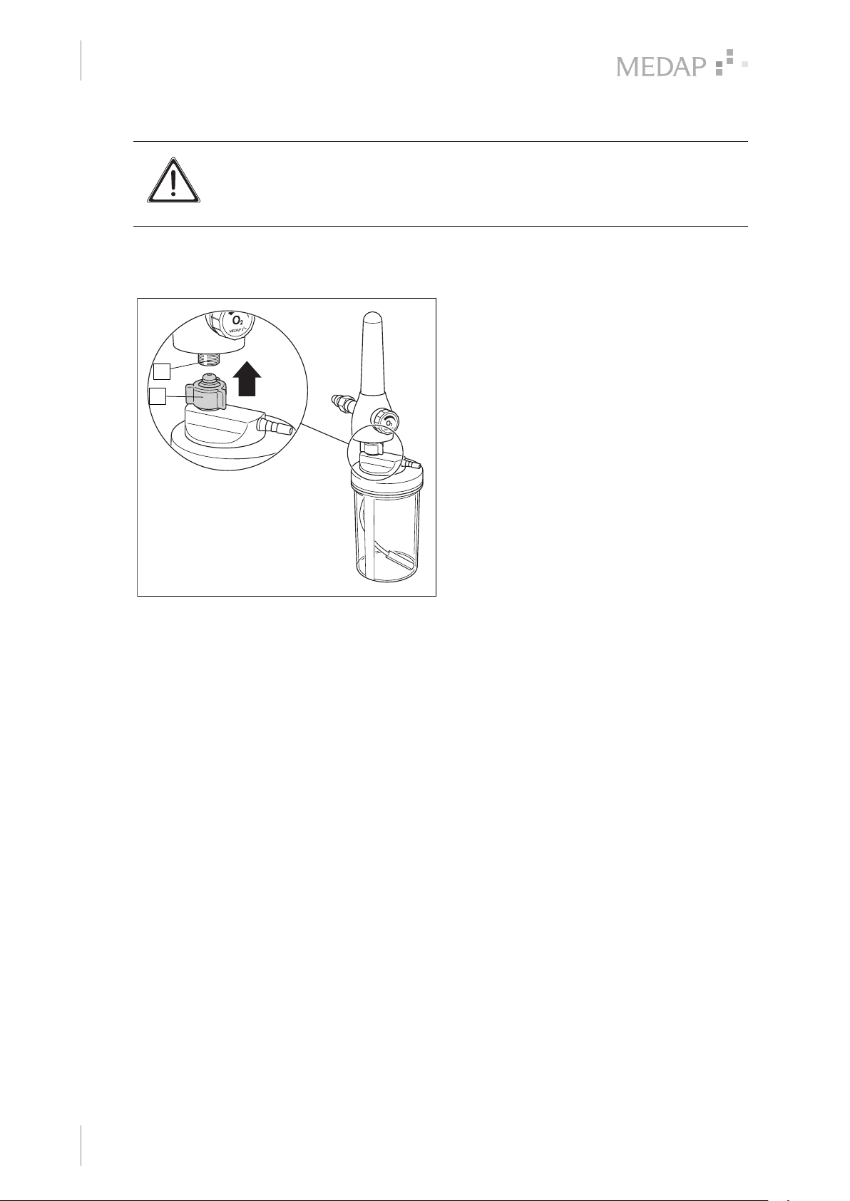
3.3.2 Connection of the bubble humidifier (REF 5752 5315)
Connecting the bubble humidifier
Ensure that the tube connector of the
bubble humidifier has two seals.
2
1
Fill the humidifier bottle up to the marking
‘Filling level’ with distilled water and screw
the bubble humidifier cap into place.
Screw the bubble humidifier cap (1) directly
onto the flowmeter outlet (2) and tighten
finger-tight until it stops.
Pay attention that no tensile forces affect
the bubble humidifier.
Fig. 4: Connection of the bubble humidifier
3.3.3 Connection of disposable humidifiers from other manufacturers
Disposable humidifiers complying with the interface description may be connected to the
flowmeter outlet.
Screw the disposable humidifier directly onto the flowmeter outlet and tighten finger-tight until
it stops.
18
GA 5752 2804 GB 18
Page 19
4 Operation
4.1 Function test
Perform a complete function check of the tapping unit prior to use. During functional testing, pay
attention to the following conditions:
Version A: Tapping unit with integrated gas pin
• The tapping unit is correctly plugged into the terminal unit.
Version B: Tapping unit with rail clamp and NIST connection
• The gas probe of the connection tube is correctly inserted in the terminal unit.
• The NIST nipple of the connection tube is correctly secured in the NIST connection of the
tapping unit.
• The NIST screw connection is tightly fastened.
• The tapping unit is locked firmly to the equipment rail.
Operation
Function test
DANGER!
Function check!
The product is used in the treatment of patients. Any restriction in the unit's
performance can result in serious complications in treatment.
Perform a complete function check every time before using the unit.
4
All versions:
• The tube connectors are firmly secured and tightly sealed, and no mechanical forces are acting on the tubes.
• The plastic and rubber components are in perfect condition and show no signs of ageing.
• The accessories are correctly connected.
• The product is leak-free.
• It is possible to variably adjust the flow rate from zero to the maximum flow.
• The product is in good hygienic condition.
4.2 Setting the flow for treatment
DANGER!
Over-pressure!
The product is under pressure whenever it is connected to the terminal unit, even if
the valve is closed.
The flowmeter viewing tube may not be unscrewed when the product is connected.
WARNING!
Compressed gas setting!
The regulating mechanism is sensitive. Make the compressed gas settings very
carefully!
NOTE
The rate of gas flow is displayed on the flowmeter viewing tube in the centre of the
indicator ball.
GA 5752 2804 GB 18
19
Page 20
4
1
Operation
Setting the flow for treatment
NOTE
When applying oxygen in its function as a medication as per the monograph in the
European Pharmaceuticals Reference, it is absolutely necessary to measure the
flow rate.
NOTE
The product only provides the patient with additional oxygen. The monitoring of the
patient is the responsibility of the user.
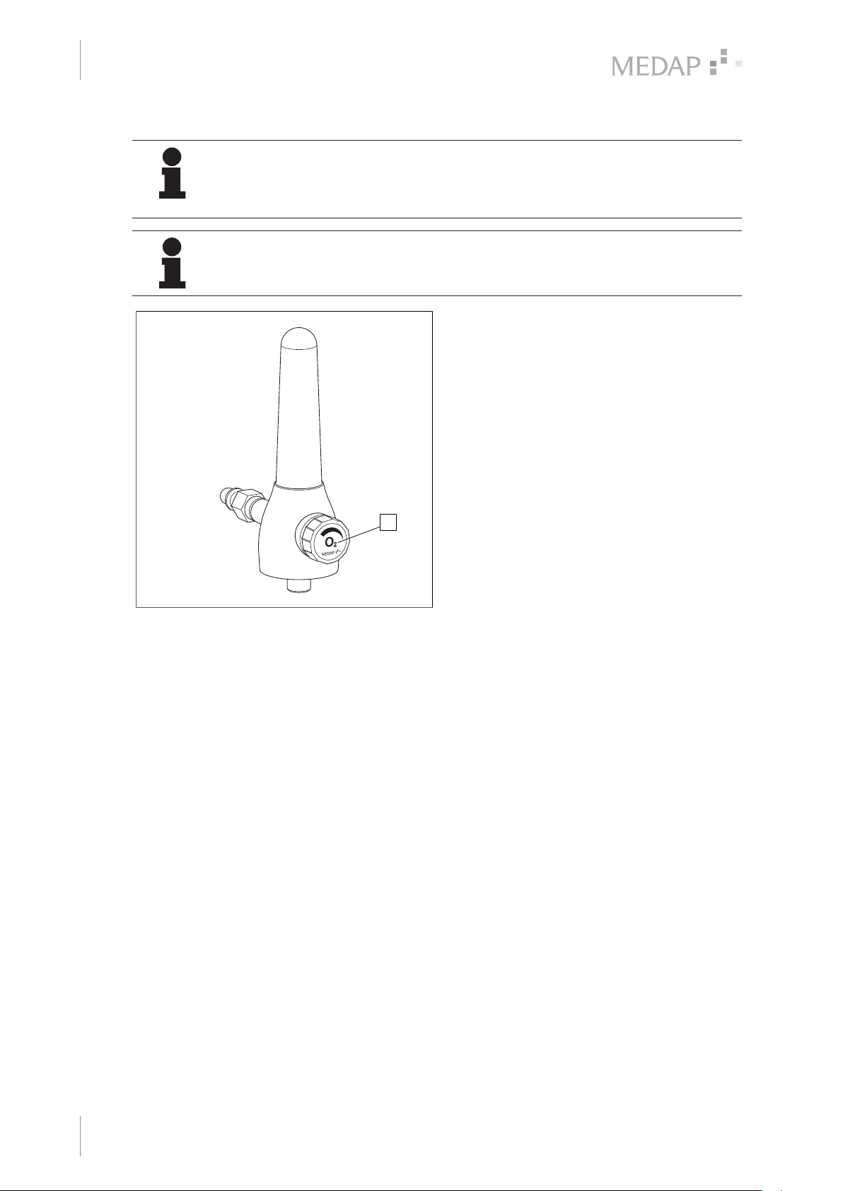
Setting the flow for treatment
Open the control valve (1) by turning it
anticlockwise. Use the control valve to set
the gas flow rate to the required value for
the treatment:
Increase the gas flow rate
Turn the control valve anticlockwise.
Fig. 5: Working with the tapping unit
Reduce the gas flow rate
Turn control valve clockwise.
1
20
GA 5752 2804 GB 18
Page 21
5 Taking the unit out of operation
WARNING!
Disengage!
When the product is disengaged (removed) from the terminal unit, the pressure
energy may cause recoil.
Use the terminal unit in parking position or support when disengaging.
NOTE
To protect the product from damages, cover with cloths when storing.
NOTE
Please refer to the manufacturer’s instructions for the particular terminal unit for
information on detaching the gas probe from the terminal unit.
All versions:
After completing treatment, close the adjustment screw by turning it clockwise and ensure that
it is closed.
Disconnect the tapping unit / gas probe from the terminal unit.
Taking the unit out of operation
Setting the flow for treatment
5
Version B: Tapping unit with rail clamp
Remove the unit from the equipment rail. For this purpose, open the handle screw and lift the
unit off the equipment rail.
GA 5752 2804 GB 18
21
Page 22
Cleaning and disinfection
6
General
6 Cleaning and disinfection
6.1 General
The product must be wipe or spray disinfected after every use.
DANGER!
Risk due to incorrect use of detergents and disinfectants!
It is strictly advised to observe the manufacturer’s instructions regarding how to
use the detergents and disinfectants as well as to observe the valid hospital
hygiene rules.
DANGER!
Infection hazard!
Product may be contaminated.
Always wear gloves for cleaning and disinfection.
DANGER!
Infection hazard!
Particles of grime may become encapsulated and cause the product not to achieve
the desired germ reduction after disinfection.
Before disinfection, the product must be cleaned thoroughly of contamination and
encapsulated particles of grime.
DANGER!
Health hazard!
The product is also used to administer respiratory gas. Residues of sterilisation
gases or other substances in the unit could endanger the patient's health.
Do not disassemble the product and do not clean it by gas sterilisation or any other
mechanical cleaning or sterilisation method. Ensure that no disinfectant or cleaning
agent enters the product.
CAUTION!
Improper cleaning and disinfection can cause property damage!
Do not use the following products for cleaning and disinfection:
• Products containing alcohol (e.g. hand disinfectants)
• Halogenides (e.g. fluorides, chlorides, bromides, iodides)
• Dehalogenating compounds (e.g. fluorine, chlorine, bromine, iodine)
• Products that may scratch the surface (e.g. scouring agents, wire brushes, wire
wool)
• Standard commercial solvents (e.g. benzene, thinner)
• Water containing iron particles
• Cleaning sponges containing iron
• Products containing hydrochloric acid
Use a soft, lint-free cloth or a soft nylon brush to clean the product.
22
CAUTION!
Improper cleaning and disinfection can cause property damage!
Use only as much detergent and disinfectant as required.
GA 5752 2804 GB 18
Page 23
6.2 Cleaning
6.2.1 General
Cleaning and disinfection
Cleaning
CAUTION!
Improper cleaning and disinfection can cause property damage!
Perform visual and functional inspections after each cleaning and disinfection
process.
NOTE
In the event that product surfaces are very dirty, carry out an additional cleaning
procedure before disinfecting the product.
NOTE
Use only all-purpose cleaners which are slightly alkaline (soap solutions) and which
contain surfactants or phosphates as active cleaning ingredients.
In the event that surfaces are heavily contaminated, use concentrated all-purpose
detergent.
6
CAUTION!
Improper cleaning can cause property damage!
Residues of physiological saline solutions (e.g. sodium chloride) can attack the
surfaces of the product.
Remove residues of physiological saline solutions with a cloth slightly dampened in
clean water. Then dry the product with a dry, lint-free cloth.
CAUTION!
Improper cleaning can cause property damage!
Do not spray cleaning agent directly into the joints or gaps and never use a highpressure cleaning unit!
6.2.2 Cleaning procedure
Use the correct dose of all-purpose detergent with water for the degree of surface
contamination and in accordance with the detergent manufacturer's instructions.
Thoroughly wipe off the product with a soft cloth slightly dampened in an all-purpose detergent
solution.
Ensure that the product is free of contamination and encapsulated particles of grime.
Thoroughly wipe off the product with a soft cloth slightly dampened in clean water.
Ensure that the product is free of detergent residues.
Dry the product with a dry, absorbent and lint-free cloth.
This will help to reduce pathogen growth on the product's surface.
Wipe or spray disinfect the product after every cleaning.
GA 5752 2804 GB 18
23
Page 24
Cleaning and disinfection
6
Disinfection
6.3 Disinfection
6.3.1 General
NOTE
In the event that product surfaces are very dirty, carry out an additional cleaning
procedure before disinfecting.
CAUTION!
Material damage due to excessive exposure times!
Exceeding the specified exposure time of the disinfectant may damage the
surfaces.
Observe the exposure time specified by the disinfectant manufacturer.
WARNING!
Disinfectants for flowmeter viewing tube!
Only the following disinfectants are approved for the instrument disinfection of the
flowmeter viewing tube:
• Indicin® Perfect* (surface disinfectant);
• Sekusept® forte S* (instrument disinfectant).
* (Registered trademark of Ecolab GmbH & Co. OHG)
6.3.2 Suitable disinfectants
Only surface disinfectants based on the following combinations of active ingredients may be used
for disinfection:
• Aldehydes
• Quaternary compounds
• Guanidine derivatives
Ingredient group Active ingredients
Aldehydes 2-ethyl-1-hexanal, formaldehyde, glutardialdehyde, glyoxal,
Quaternary compounds Alkyl-didecyl-polyoxethyl ammonium propionate, alkyl-dimethyl-
o-phthaldialdehyde, succinaldehyde
alkylbenzyl ammonium chloride, alkyl-dimethyl-ethyl ammonium
chloride, alkyl-dimethyl-ethylbenzyl ammonium chloride,
benzalkonium propionate, benzalkonium chloride (alkyl-dimethylbenzyl ammonium chloride, coco-dimethyl-benzyl ammonium
chloride, lauryl-dimethylbenzyl ammonium chloride, myristyldimethyl-benzyl ammonium chloride), benzethonium chloride,
benzyl-dihydroxyethyl-coco-alkyl ammonium chloride, dialkyldimethyl ammonium chloride (didecyldimethyl ammonium chloride),
didecyl-methyl-oxyethyl ammonium propionate, mecetronium-ethyl
sulfate, methyl-benzethonium chloride, n-octyl-dimethyl-benzyl
ammonium chloride
24
Guanidine derivatives Alkyl-biguanide, chlorhexidine-digluconate, cocospropylene-
diamine guanidinium diacetate, oliogomeric biguanide,
polyhexamethylene biguanide hydrochloride (oligo-diimino imiodocarbonyl imino-hexamethylene, polyhexanide)
Tab. 4: Active ingredients of disinfectants
GA 5752 2804 GB 18
Page 25
6.3.3 Disinfection procedure
After each cleaning process, wipe or spray disinfect the product in accordance with the
instructions of the disinfectant manufacturer.
Ensure that the product is free of disinfectant residue.
Perform visual and functional inspections.
6.4 Special safety notes
DANGER!
Tension cracks!
Various components in the tapping unit are made of plastic materials. Solvents and
some disinfectants and some cleaning agents can soften plastic or cause tension
fissures. The gas pressure may cause the flowmeter viewing tube to burst.
Never use detergents that contain alcohol. Observe cleaning and disinfection
standards.
CAUTION!
Property damage!
Using non-colour-fast surgical drapes can cause discolouration of surfaces.
Only use colour-fast surgical drapes.
Cleaning and disinfection
Special safety notes
6
GA 5752 2804 GB 18
25
Page 26
Maintenance
7
General
7 Maintenance
7.1 General
Maintenance, repairs and periodic tests may only be carried out by persons who have the
appropriate technical knowledge and are familiar with the product. To carry out these measures,
the person must have the necessary test devices and original spare parts.
ATMOS recommends: Work should be carried out by an authorised ATMOS service partner. This
ensures that repairs and testing are carried out professionally, original spare parts are used and
warranty claims remain unaffected.
DANGER!
Health hazard!
The product is used in the treatment of patients. The product or some of its
components may be contaminated.
Clean and disinfect the product before maintenance and repair. Repair work may
be performed by personnel authorised by ATMOS.
7.2 Periodic tests
Observe country-specific requirements regarding periodic tests.
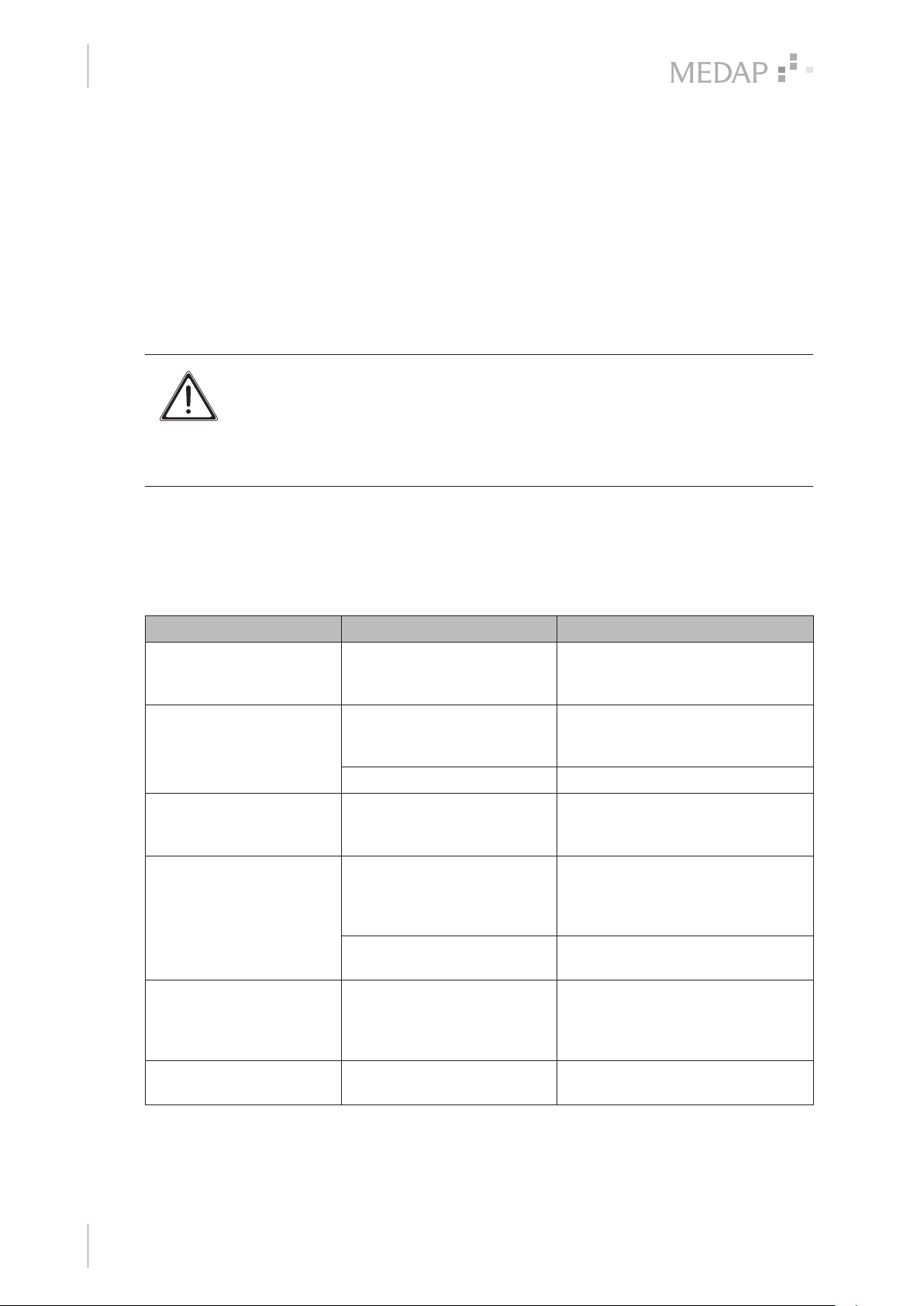
7.3 Malfunctions and troubleshooting
Defect Source of malfunction Troubleshooting
Indicator ball does not rise
even when the control
valve is completely open
15 l/min are not reached
with the control valve
opened fully
Incorrect display of
flowmeter
Indicator ball does not rest
on seat with the control
valve in the closed position
Gas pin for gas supply is only
locked in the parking position
The pressure from the central
gas supply system is not high
enough
Sintered filter is clogged Have the sintered filter replaced
Pressure fluctuations in the
central gas supply system;
pressure is too low or too high
Flowmeter viewing tube
defective
Control valve is no longer
sealing
Bring gas pin for gas supply into the
operating position, i.e. push the gas
pin in completely
Check the pressure supplied by the
central gas supply system
Contact Technical Service
Have flowmeter viewing tube and
indicator ball replaced. Attention:
flowmeter viewing tube and
indicator ball function as a pair
Have flowmeter inspected
26
Indicator ball is stuck Flowmeter viewing tube is
Gas probe does not fit into
the terminal unit
GA 5752 2804 GB 18
Have flowmeter viewing tube
contaminated
Wrong terminal unit selected Check the designation of the
cleaned. Attention: indicator ball
and flowmeter viewing tube function
as a pair
terminal unit
Page 27
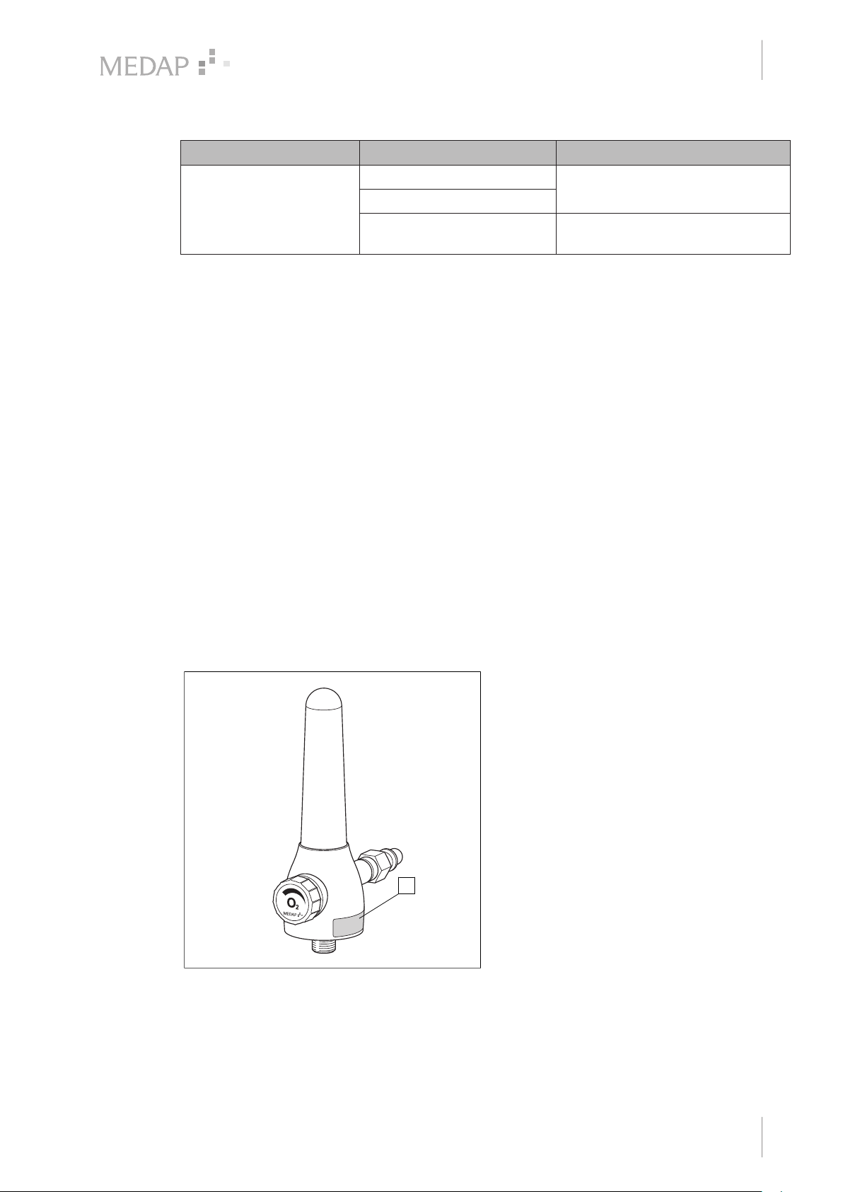
Defect Source of malfunction Troubleshooting
1
Maintenance
Repairs
7
Full loss of pressure at the
flowmeter
Tab. 5: Malfunctions and troubleshooting
7.4 Repairs
The following issues may require repairs by the manufacturer or an authorised service partner:
• Liquid has penetrated the device.
• Performance has significantly decreased.
• Inexplicable notifications appear.
• Abnormal noises occur.
• Functional faults cannot be rectified according to the measures in chapter Malfunctions and
troubleshooting [ page 26].
If defects are detected, the product may not be used any longer.
Make a note of the defects and the REF number on the type plate and inform your ATMOS
representative.
Observe the information in chapter Sending in the device [ page 27].
7.5 Service hotline
+49 7653 689-0
Seal is missing or defective Have flowmeter inspected
There is a leak in the housing
Accessories are not tightened Ensure that the accessory is fitted
properly
7.6 Type plate position
Fig. 6: Type plate
7.7 Sending in the device
Remove and properly dispose of consumables.
Clean and disinfect the product and accessories according to the operating instructions.
Position of the type plate (1) on the product.
1
GA 5752 2804 GB 18
27
Page 28

7
Maintenance
Sending in the device
Place used accessories with the product.
Fill in form QD 434 ‘Delivery complaint / return shipment’ and the respective decontamination
certificate.
This form is enclosed with each delivery and can be found at www.atmosmed.com.
The device must be well padded and packed in suitable packaging.
Place form QD 434 ‘Delivery complaint / return shipment’ and the respective decontamination
certificate in an envelope.
Affix the envelope to the outside of the package.
Send the product to ATMOS or to your dealer.
28
GA 5752 2804 GB 18
Page 29
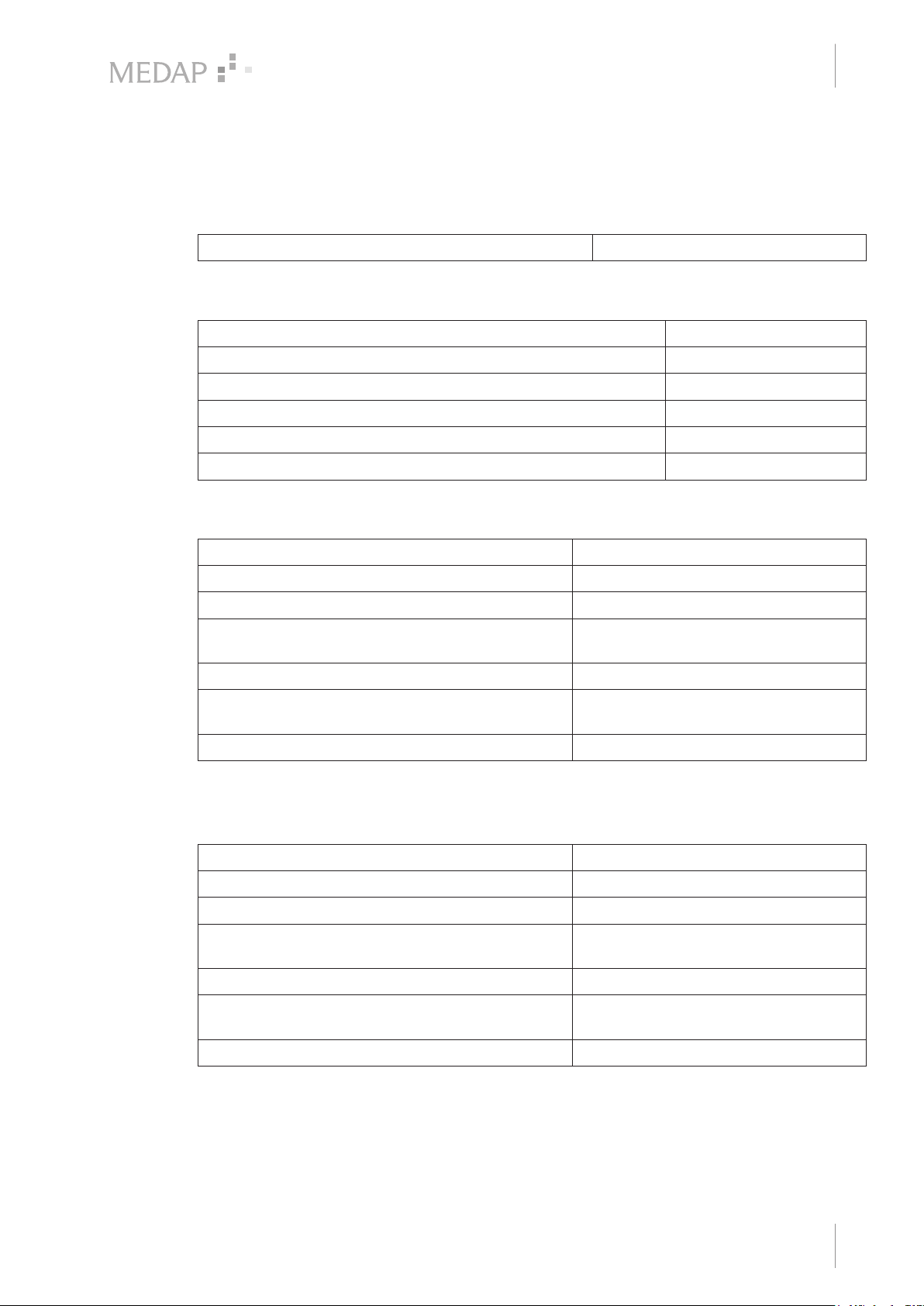
8 Technical specifications
8.1 General
Classification as per Annex IX to Directive 93/42/EEC Class IIa
8.2 Ambient conditions
Temperature: Shipping / storage −15 °C to +50 °C
Temperature: Operation +15 °C to +40 °C
Relative humidity: Shipping / storage 10% to 95%
Relative humidity: Operation 30% to 75%
Atmospheric pressure: Shipping / storage 700 hPa to 1060 hPa
Atmospheric pressure: Operation 700 hPa to 1060 hPa
Technical specifications
General
8
8.3 FINA FLOW O 15 / A 15
Measurement range 1–15 l/min
Supply pressure 500 kPa* ± 10%
Input filter (only with DIN version) Sintered metal 80 μm pore width
Indication accuracy (freeflow at 500 kPa) ± 10% over 5 l/min flow indication ± 0.5 l/
Flow limitation 20 l/min ± 5 l/min
Weight Approximately 750 to 950 g (depending
Dimensions (W x H x D) Approximately 50 x 70 x 140 mm
* 100 kPa = 1 bar = 1000 mbar = 750 mmHg
8.4 FINA DFLOW O 15
Measurement range 1–15 l/min
Supply pressure 500 kPa* ± 10%
Input filter (only with DIN version) Sintered metal 80 μm pore width
Indication accuracy (freeflow at 500 kPa) ± 10% over 5 l/min flow indication
min to 5 l/min flow indication
on attachment)
± 0.5 l/min to 5 l/min flow indication
Flow limitation 20 l/min ± 5 l/min
Weight Approximately 1600 to 1700 g
(depending on attachment)
Dimensions (W x H x D) Approximately 165 x 170 x 120 mm
* 100 kPa = 1 bar = 1000 mbar = 750 mmHg
GA 5752 2804 GB 18
29
Page 30

Approved accessories
9
Accessories
9 Approved accessories
The following accessories are not part of the scope of delivery and must be ordered separately.
9.1 Accessories
5752 2746 Tube adapter, metal 4 mm, 6 mm, 8 mm
5752 5316 Tube adapter, plaic 4 mm, 6 mm, 8 mm
5752 5315 Bubble humidier
5752 5707 Flow selector
Tab. 6: Accessories
9.2 Scope of delivery
5750 3774 Neutral colour coding label (AIR versions)
5750 3771 Neutral colour coding label (O2 versions)
Tab. 7: Scope of delivery
30
GA 5752 2804 GB 18
Page 31

Notes
Page 32

Manufacturer:
ATMOS
MedizinTechnik GmbH & Co. KG
Ludwig-Kegel-Str. 16
79853 Lenzkirch
GERMANY
Phone: +49 7653 689-0
www.atmosmed.com
 Loading...