

Page 1
The Complete
Reference Guide
VisualCAD/CAM 2024 MILL
Published: May 2024
MecSoft Corpotation
© Copyright 1998-2024
Page 2

VisualCAD/CAM-MILL 2024 Reference
by MecSoft Corporation
User Notes:
________________________________
________________________________
________________________________
________________________________
________________________________
________________________________
________________________________
________________________________
________________________________
________________________________
________________________________
________________________________
________________________________
________________________________
________________________________
________________________________
________________________________
________________________________
________________________________
________________________________
Page 3

Table of Contents
2Contents
Quick Start
Resource Guide
Welcome
................................................................................................................................... 241 Overview
................................................................................................................................... 252 Configurations
................................................................................................................................... 323 Understanding
................................................................................................................................... 344 Work flow
................................................................................................................................... 365 Post-Processing
User Interface
................................................................................................................................... 381 VisualCAM Menu Item
................................................................................................................................... 382 MILL Browsers
................................................................................................................................... 383 Machining Browser
................................................................................................................................... 474 Machining Objects (Mobs) Browser
................................................................................................................................... 605 Right-Click Commands
................................................................................................................................... 676 Docking Browsers
................................................................................................................................... 697 CAM Preferences
20
23
24
37
.......................................................................................................................................................... 39Browser Toggle Tabs
.......................................................................................................................................................... 40Program Tab
.......................................................................................................................................................... 44Simulate Tab
.......................................................................................................................................................... 48Tools Tab
.......................................................................................................................................................... 52Regions Tab
.......................................................................................................................................................... 56Features Tab
.......................................................................................................................................................... 59K-Bases Tab
.......................................................................................................................................................... 69Geometry
.......................................................................................................................................................... 71Features
.......................................................................................................................................................... 73Stock
.......................................................................................................................................................... 75Cutting Tools
.......................................................................................................................................................... 76Feeds & Speeds
.......................................................................................................................................................... 78Machining
......................................................................................................................................................... 80Multi-threading Manager
.......................................................................................................................................................... 82Output Control
.......................................................................................................................................................... 84Toolpath
.......................................................................................................................................................... 86Simulation
.......................................................................................................................................................... 90User Interface
.......................................................................................................................................................... 95Post Preferences
.......................................................................................................................................................... 99Licensing
Overview of Machining Methods
© 2024 MecSoft Corporation
102
2
Page 4

VisualCAD/CAM-MILL 2024 Reference3
................................................................................................................................... 1021 2½ Axis Operations
.......................................................................................................................................................... 104Control Matrix
.......................................................................................................................................................... 110Face Top
.......................................................................................................................................................... 110Roughing
.......................................................................................................................................................... 111Facing
.......................................................................................................................................................... 113Pocketing
.......................................................................................................................................................... 114Profiling
.......................................................................................................................................................... 115V-Carve Finishing
.......................................................................................................................................................... 116V-Carve Roughing
.......................................................................................................................................................... 117Chamfering
.......................................................................................................................................................... 117Filleting
.......................................................................................................................................................... 118Engraving
.......................................................................................................................................................... 119Hole Pocketing
.......................................................................................................................................................... 120Hole Profiling
.......................................................................................................................................................... 120Thread Milling
.......................................................................................................................................................... 121T-Slotting
.......................................................................................................................................................... 122Saw Cutting
.......................................................................................................................................................... 123Re-Machining
.......................................................................................................................................................... 123Drag Knife Cutting
................................................................................................................................... 1242 3 Axis Operations
.......................................................................................................................................................... 125Control Matrix
.......................................................................................................................................................... 128Horizontal Roughing
.......................................................................................................................................................... 130Parallel Finishing
.......................................................................................................................................................... 131Horizontal Finishing
.......................................................................................................................................................... 131Radial Machining
.......................................................................................................................................................... 132Spiral Machining
................................................................................................................................... 1323 3 Axis Advanced Operations
.......................................................................................................................................................... 134Control Matrix
.......................................................................................................................................................... 137Adaptive Roughing
.......................................................................................................................................................... 138Plunge Roughing
.......................................................................................................................................................... 139Horizontal Re-Roughing
.......................................................................................................................................................... 139Plunge Re-Roughing
.......................................................................................................................................................... 140Clear Flats Machining
.......................................................................................................................................................... 141Projection Pocketing
.......................................................................................................................................................... 1413D Offset Pocketing
.......................................................................................................................................................... 1423D Offset Profiling
.......................................................................................................................................................... 143Pencil Tracing
.......................................................................................................................................................... 144Valley Re machining
.......................................................................................................................................................... 144Flats (Plateau) Machining
.......................................................................................................................................................... 145Steeps (Parallel Hill) Machining
.......................................................................................................................................................... 145Steeps Z (Horizontal Hill) Finishing
.......................................................................................................................................................... 146Curve Machining
.......................................................................................................................................................... 147Betw een 2 Curves Machining
.......................................................................................................................................................... 147Reverse Post Milling
................................................................................................................................... 1484 4 Axis Operations
.......................................................................................................................................................... 150Control Matrix
.......................................................................................................................................................... 153Rotate Table
.......................................................................................................................................................... 154Rotary Instance Operation
.......................................................................................................................................................... 1574 Axis Create Round
.......................................................................................................................................................... 1584 Axis Facing
.......................................................................................................................................................... 1594 Axis Pocketing
.......................................................................................................................................................... 1604 Axis Profiling
.......................................................................................................................................................... 1604 Axis R-Level Roughing
© 2024 MecSoft Corporation
Page 5

.......................................................................................................................................................... 1614 Axis R-Level Finishing
.......................................................................................................................................................... 1624 Axis Parallel Finishing
.......................................................................................................................................................... 1634 Axis Projection Pocketing
.......................................................................................................................................................... 1634 Axis Engraving
.......................................................................................................................................................... 1644 Axis Drive Surface
................................................................................................................................... 1655 Drilling (Hole Making) Operations
.......................................................................................................................................................... 169Control Matrix
.......................................................................................................................................................... 172Drilling
.......................................................................................................................................................... 173Tapping
.......................................................................................................................................................... 173Boring
.......................................................................................................................................................... 174Reverse Boring
................................................................................................................................... 1756 4 Axis Hole Making
.......................................................................................................................................................... 176Control Matrix
.......................................................................................................................................................... 178Drilling
.......................................................................................................................................................... 179Tapping
.......................................................................................................................................................... 180Boring
.......................................................................................................................................................... 181Reverse Boring
................................................................................................................................... 1827 5 Axis Overview
.......................................................................................................................................................... 183Control Matrix
.......................................................................................................................................................... 186Indexed 5 Axis Machining Operations
.......................................................................................................................................................... 187Using Set CSYS Setup for Orientation
.......................................................................................................................................................... 189Simultaneous 5 Axis Machining Operations
.......................................................................................................................................................... 190Curve Projection Machining
.......................................................................................................................................................... 191Flow Curve
.......................................................................................................................................................... 192Betw een 2 Curves
.......................................................................................................................................................... 193Drive Curve
.......................................................................................................................................................... 194Surface Norm al
.......................................................................................................................................................... 195Swarf Machining
4Contents
Creating Machining Operations
................................................................................................................................... 1961 Machine
.......................................................................................................................................................... 196Manual Definition
.......................................................................................................................................................... 205Load From File
................................................................................................................................... 2092 Geometry
.......................................................................................................................................................... 209Part Geometry
.......................................................................................................................................................... 210Stock Geometry
......................................................................................................................................................... 211Box Stock
......................................................................................................................................................... 213Part Box Stock
......................................................................................................................................................... 215Cylinder Stock
......................................................................................................................................................... 218Part Cylinder Stock
......................................................................................................................................................... 220Part Offset Stock
......................................................................................................................................................... 221Extrude Stock
......................................................................................................................................................... 224Stock from Selection
......................................................................................................................................................... 225Export Stock as STL
......................................................................................................................................................... 226Delete Stock
......................................................................................................................................................... 227Remove Simulations
.......................................................................................................................................................... 228Fixture Geometry
................................................................................................................................... 2323 Setup
.......................................................................................................................................................... 234Orient Part
.......................................................................................................................................................... 237CSYS Setup
.......................................................................................................................................................... 244Rotate Table Setup
196
© 2024 MecSoft Corporation
4
Page 6

VisualCAD/CAM-MILL 2024 Reference5
................................................................................................................................... 2484 Align Stock
................................................................................................................................... 2495 Set World CS
................................................................................................................................... 2546 Material
................................................................................................................................... 2567 Work Zero
................................................................................................................................... 2618 Control Geometry
................................................................................................................................... 3099 Cutting Tools
.......................................................................................................................................................... 264Selecting Regions in Machining Operations
......................................................................................................................................................... 266Select Part/Containment Regions
......................................................................................................................................................... 269Selecting Surface Boundaries
......................................................................................................................................................... 272Select Flat Area Features
......................................................................................................................................................... 274Avoid Regions
......................................................................................................................................................... 275Start Points
......................................................................................................................................................... 276Select Pre-Defined Regions
......................................................................................................................................................... 278Select Features for Machining Operations
.......................................................................................................................................................... 281Predefined Machining Regions
......................................................................................................................................................... 282Create Machining Region Set
......................................................................................................................................................... 282Select Curve
......................................................................................................................................................... 283Select Surface Edge Areas
......................................................................................................................................................... 284Flat Areas Selection Filter
......................................................................................................................................................... 286Select Flat Areas
......................................................................................................................................................... 287Select Start Point
......................................................................................................................................................... 288Reverse Cut Direction
......................................................................................................................................................... 289Automatic Bridge Points on Selections
......................................................................................................................................................... 290Manual Bridge Points on Selections
......................................................................................................................................................... 291Delete All Bridge Points in Selections
......................................................................................................................................................... 291Edit Bridge Point in Selections
......................................................................................................................................................... 293Clone Machining Region
......................................................................................................................................................... 295Editing Predefined Regions
.......................................................................................................................................................... 295Machining Region Methods, 3 Axis
......................................................................................................................................................... 296Flat Area Regions
......................................................................................................................................................... 298Silhouette Regions
......................................................................................................................................................... 300Valley Regions
......................................................................................................................................................... 305Check Regions
......................................................................................................................................................... 307Collision Regions
.......................................................................................................................................................... 311Create Edit Tools
.......................................................................................................................................................... 318Feeds & Speeds
......................................................................................................................................................... 321Feeds & Speeds Calculator
.......................................................................................................................................................... 323Create Edit Tool Holders
.......................................................................................................................................................... 325Adjust Register
.......................................................................................................................................................... 325Cutcom Register
.......................................................................................................................................................... 326Axial Offset
.......................................................................................................................................................... 326Coolant
.......................................................................................................................................................... 326Comments
.......................................................................................................................................................... 327Save Tool Library
.......................................................................................................................................................... 327Load Tool Library
.......................................................................................................................................................... 328Add Tool to Library
.......................................................................................................................................................... 329Unload Tool Library
.......................................................................................................................................................... 329Select Tools from Library
.......................................................................................................................................................... 330List Tools
.......................................................................................................................................................... 331User Defined Tools
.......................................................................................................................................................... 334Compute Tool & Part Collisions
.......................................................................................................................................................... 337Cutter Compensation
© 2024 MecSoft Corporation
Page 7

................................................................................................................................... 33810 Feeds and Speeds
.......................................................................................................................................................... 348Load from File
................................................................................................................................... 35011 Clearance Plane
................................................................................................................................... 35612 High Speed Machining
................................................................................................................................... 35713 Features
.......................................................................................................................................................... 358Features Tab
.......................................................................................................................................................... 362Automatic Feature Detection (AFD)
.......................................................................................................................................................... 363Interactive Feature Detection (IFD)
.......................................................................................................................................................... 363Automatic Feature Machining (AFM)
.......................................................................................................................................................... 369Interactive Feature Machining (IFM)
.......................................................................................................................................................... 371Set Filters for Feature Detection
.......................................................................................................................................................... 373List Features
.......................................................................................................................................................... 374Know ledge Base for Milling Features
.......................................................................................................................................................... 377Know ledge Base for Hole Features
......................................................................................................................................................... 379Hole Features Recognized
......................................................................................................................................................... 380Select from Matching Know ledge Bases
......................................................................................................................................................... 382Hole Feature Cross-Section Rules
................................................................................................................................... 38514 Knowledge Base
.......................................................................................................................................................... 386Create Know ledge Base (KB)
.......................................................................................................................................................... 389Load KB
.......................................................................................................................................................... 391Set KB Geometry Selection Rules
.......................................................................................................................................................... 397Set KB Stock Definition Rules
.......................................................................................................................................................... 399Apply Knowledge Base
................................................................................................................................... 40215 Create Miscellaneous Operations
.......................................................................................................................................................... 403Mop Set
.......................................................................................................................................................... 404Machine Control
.......................................................................................................................................................... 406Fixture Offsets
.......................................................................................................................................................... 409XY Instance
................................................................................................................................... 41316 Tools and Utilities
.......................................................................................................................................................... 413Save as Defaults
.......................................................................................................................................................... 417Post Process Generator ...
.......................................................................................................................................................... 418Explode Cabinet Design ...
................................................................................................................................... 42317 Troubleshooting Error Messages
6Contents
Creating 2½ Axis Operations
................................................................................................................................... 4271 2½ Axis Control Matrix
................................................................................................................................... 4322 Face Top
.......................................................................................................................................................... 435Tool
.......................................................................................................................................................... 438Feeds & Speeds
.......................................................................................................................................................... 448Clearance Plane
.......................................................................................................................................................... 454Cut Param eters
.......................................................................................................................................................... 458Cut Levels
.......................................................................................................................................................... 460Entry/Exit
.......................................................................................................................................................... 463Advanced Cut Parameters
................................................................................................................................... 4673 Roughing
.......................................................................................................................................................... 470Control Geometry
.......................................................................................................................................................... 474Tool
.......................................................................................................................................................... 476Feeds & Speeds
.......................................................................................................................................................... 486Clearance Plane
.......................................................................................................................................................... 492Cut Param eters
© 2024 MecSoft Corporation
427
6
Page 8

VisualCAD/CAM-MILL 2024 Reference7
.......................................................................................................................................................... 501Cut Levels
.......................................................................................................................................................... 504Engage/Retract
.......................................................................................................................................................... 507Advanced Cut Parameters
................................................................................................................................... 5114 Facing
.......................................................................................................................................................... 513Control Geometry
.......................................................................................................................................................... 517Roughing
.......................................................................................................................................................... 524Cut Levels
.......................................................................................................................................................... 530Cut Levels, Features
.......................................................................................................................................................... 533Entry/Exit
.......................................................................................................................................................... 537Advanced Cut Parameters
.......................................................................................................................................................... 541Tool
.......................................................................................................................................................... 543Feeds & Speeds
.......................................................................................................................................................... 553Clearance Plane
................................................................................................................................... 5595 Pocketing
.......................................................................................................................................................... 561Control Geometry
.......................................................................................................................................................... 565Cut Param eters
.......................................................................................................................................................... 572Pocketing Entry/Exit
.......................................................................................................................................................... 575Sorting
.......................................................................................................................................................... 579Cut Levels
.......................................................................................................................................................... 585Cut Levels, Features
.......................................................................................................................................................... 588Advanced Cut Parameters
.......................................................................................................................................................... 592Tool
.......................................................................................................................................................... 594Feeds & Speeds
.......................................................................................................................................................... 604Clearance Plane
.......................................................................................................................................................... 610About High Speed Pocketing
................................................................................................................................... 6116 Differences between Facing and Pocket Machining
................................................................................................................................... 6117 Profiling
.......................................................................................................................................................... 615Control Geometry
.......................................................................................................................................................... 618Cut Param eters
.......................................................................................................................................................... 624Cut Levels
.......................................................................................................................................................... 630Cut Levels, Features
.......................................................................................................................................................... 633Entry/Exit
.......................................................................................................................................................... 637Advanced Cut Parameters
.......................................................................................................................................................... 641Cornering Parameters
.......................................................................................................................................................... 645Sorting
.......................................................................................................................................................... 649Tool
.......................................................................................................................................................... 651Feeds & Speeds
.......................................................................................................................................................... 661Clearance Plane
................................................................................................................................... 6678 V-Carve Roughing
.......................................................................................................................................................... 669Control Geometry
.......................................................................................................................................................... 672Cut Param eters
.......................................................................................................................................................... 677Cut Levels
.......................................................................................................................................................... 683Pocketing Entry/Exit
.......................................................................................................................................................... 686Advanced Cut Parameters
.......................................................................................................................................................... 690Tool
.......................................................................................................................................................... 692Feeds & Speeds
.......................................................................................................................................................... 702Clearance Plane
................................................................................................................................... 7089 V-Carving
.......................................................................................................................................................... 710Control Geometry
.......................................................................................................................................................... 713Cut Param eters
.......................................................................................................................................................... 716Tool
.......................................................................................................................................................... 718Feeds & Speeds
© 2024 MecSoft Corporation
Page 9

................................................................................................................................... 73810 Engraving
................................................................................................................................... 77611 Slotting
................................................................................................................................... 81612 Chamfering
................................................................................................................................... 86113 Filleting
................................................................................................................................... 90314 Hole Pocketing
................................................................................................................................... 94515 Hole Profiling
8Contents
.......................................................................................................................................................... 728Clearance Plane
.......................................................................................................................................................... 734Sorting
.......................................................................................................................................................... 740Control Geometry
.......................................................................................................................................................... 743Cut Param eters
.......................................................................................................................................................... 746Entry/Exit
.......................................................................................................................................................... 749Advanced Cut Parameters
.......................................................................................................................................................... 754Tool
.......................................................................................................................................................... 756Feeds & Speeds
.......................................................................................................................................................... 766Clearance Plane
.......................................................................................................................................................... 772Sorting
.......................................................................................................................................................... 778Control Geometry
.......................................................................................................................................................... 782Slot Parameters
.......................................................................................................................................................... 786Pocketing Entry/Exit
.......................................................................................................................................................... 789Sorting
.......................................................................................................................................................... 793Cut Levels
.......................................................................................................................................................... 795Cut Levels, Features
.......................................................................................................................................................... 798Tool
.......................................................................................................................................................... 800Feeds & Speeds
.......................................................................................................................................................... 810Clearance Plane
.......................................................................................................................................................... 819Control Geometry
.......................................................................................................................................................... 822Cut Param eters
.......................................................................................................................................................... 828Entry/Exit
.......................................................................................................................................................... 832Hole Features
.......................................................................................................................................................... 834Tool
.......................................................................................................................................................... 837Feeds & Speeds
.......................................................................................................................................................... 847Clearance Plane
.......................................................................................................................................................... 853Advanced Cut Parameters
.......................................................................................................................................................... 857Sorting
.......................................................................................................................................................... 863Control Geometry
.......................................................................................................................................................... 867Cut Param eters
.......................................................................................................................................................... 872Entry/Exit
.......................................................................................................................................................... 877Tool
.......................................................................................................................................................... 879Feeds & Speeds
.......................................................................................................................................................... 889Clearance Plane
.......................................................................................................................................................... 895Advanced Cut Parameters
.......................................................................................................................................................... 899Sorting
.......................................................................................................................................................... 905Control Geometry
.......................................................................................................................................................... 908Cut Param eters
.......................................................................................................................................................... 918Entry/Exit
.......................................................................................................................................................... 919Sorting
.......................................................................................................................................................... 924Hole Features
.......................................................................................................................................................... 927Tool
.......................................................................................................................................................... 929Feeds & Speeds
.......................................................................................................................................................... 939Clearance Plane
.......................................................................................................................................................... 947Control Geometry
.......................................................................................................................................................... 950Cut Param eters
© 2024 MecSoft Corporation
8
Page 10

VisualCAD/CAM-MILL 2024 Reference9
.......................................................................................................................................................... 955Entry/Exit
.......................................................................................................................................................... 959Sorting
.......................................................................................................................................................... 963Hole Features
.......................................................................................................................................................... 965Tool
.......................................................................................................................................................... 968Feeds & Speeds
.......................................................................................................................................................... 978Clearance Plane
................................................................................................................................... 98416 Thread Milling
.......................................................................................................................................................... 986Control Geometry
.......................................................................................................................................................... 990Cut Param eters
.......................................................................................................................................................... 995Entry/Exit
.......................................................................................................................................................... 997Tool
.......................................................................................................................................................... 999Feeds & Speeds
.......................................................................................................................................................... 1009Clearance Plane
................................................................................................................................... 101517 T-Slotting
.......................................................................................................................................................... 1017Control Geometry
......................................................................................................................................................... 1021for T-Slotting
.......................................................................................................................................................... 1021Cut Parameters
.......................................................................................................................................................... 1026Cut Control
.......................................................................................................................................................... 1027Entry/Exit
.......................................................................................................................................................... 1032Tool
.......................................................................................................................................................... 1034Feeds & Speeds
.......................................................................................................................................................... 1044Clearance Plane
................................................................................................................................... 105018 Knife Cutting
.......................................................................................................................................................... 1051Control Geometry
.......................................................................................................................................................... 1054Cut Parameters
.......................................................................................................................................................... 1057Entry/Exit
.......................................................................................................................................................... 1061Sorting
.......................................................................................................................................................... 1065Tool
.......................................................................................................................................................... 1067Feeds & Speeds
.......................................................................................................................................................... 1073Clearance Plane
................................................................................................................................... 107919 Saw Cutting
.......................................................................................................................................................... 1081Control Geometry
.......................................................................................................................................................... 1084Tool
.......................................................................................................................................................... 1087Feeds & Speeds
.......................................................................................................................................................... 1097Cut Parameters
.......................................................................................................................................................... 1104Clearance Plane
.......................................................................................................................................................... 1109Entry/Exit
................................................................................................................................... 111420 Re-Machining
.......................................................................................................................................................... 1117Control Geometry
.......................................................................................................................................................... 1120Cut Parameters
.......................................................................................................................................................... 1125Cut Levels
.......................................................................................................................................................... 1131Entry/Exit
.......................................................................................................................................................... 1135Advanced Cut Parameters
.......................................................................................................................................................... 1139Tool
.......................................................................................................................................................... 1141Feeds & Speeds
.......................................................................................................................................................... 1151Clearance Plane
Creating 2½ Hole Making
................................................................................................................................... 11581 Drill Control Matrix
................................................................................................................................... 11602 Drilling
.......................................................................................................................................................... 1163Hole Features
1158
© 2024 MecSoft Corporation
Page 11

.......................................................................................................................................................... 1171Tool
.......................................................................................................................................................... 1173Feeds & Speeds
.......................................................................................................................................................... 1177Clearance
.......................................................................................................................................................... 1181Cut Parameters
.......................................................................................................................................................... 1185Sorting
................................................................................................................................... 11893 Tapping
.......................................................................................................................................................... 1191Hole Features
.......................................................................................................................................................... 1199Tool
.......................................................................................................................................................... 1201Feeds & Speeds
.......................................................................................................................................................... 1205Tapping Feedrates
.......................................................................................................................................................... 1206Clearance
.......................................................................................................................................................... 1209Cut Parameters
.......................................................................................................................................................... 1212Sorting
................................................................................................................................... 12164 Boring
.......................................................................................................................................................... 1218Hole Features
.......................................................................................................................................................... 1226Tool
.......................................................................................................................................................... 1228Feeds & Speeds
.......................................................................................................................................................... 1232Clearance
.......................................................................................................................................................... 1236Cut Parameters
.......................................................................................................................................................... 1239Sorting
................................................................................................................................... 12435 Reverse Boring
.......................................................................................................................................................... 1245Hole Features
.......................................................................................................................................................... 1253Tool
.......................................................................................................................................................... 1255Feeds & Speeds
.......................................................................................................................................................... 1259Clearance
.......................................................................................................................................................... 1263Cut Parameters
.......................................................................................................................................................... 1266Sorting
10Contents
Creating 3 Axis Operations
................................................................................................................................... 12711 3 Axis Control Matrix
................................................................................................................................... 12752 Horizontal Roughing
.......................................................................................................................................................... 1277Control Geometry
.......................................................................................................................................................... 1284Cut Parameters
.......................................................................................................................................................... 1292Cut Levels
.......................................................................................................................................................... 1296Engage/Retract
.......................................................................................................................................................... 1298Advanced Cut Parameters
.......................................................................................................................................................... 1302Tool
.......................................................................................................................................................... 1304Feeds & Speeds
.......................................................................................................................................................... 1314Clearance Plane
................................................................................................................................... 13203 Parallel Finishing
.......................................................................................................................................................... 1323Control Geometry
.......................................................................................................................................................... 1330Cut Parameters
.......................................................................................................................................................... 1334Advanced Cut Parameters
.......................................................................................................................................................... 1338Z Containment
.......................................................................................................................................................... 1340Entry/Exit
.......................................................................................................................................................... 1343Tool
.......................................................................................................................................................... 1345Feeds & Speeds
.......................................................................................................................................................... 1355Clearance Plane
.......................................................................................................................................................... 1361Sorting
................................................................................................................................... 13654 Horizontal Finishing
.......................................................................................................................................................... 1368Control Geometry
1271
© 2024 MecSoft Corporation
10
Page 12

VisualCAD/CAM-MILL 2024 Reference11
................................................................................................................................... 14115 Spiral Machining
................................................................................................................................... 14476 Radial Machining
.......................................................................................................................................................... 1375Cut Parameters
.......................................................................................................................................................... 1378Advanced Cut Parameters
.......................................................................................................................................................... 1382Cut Levels
.......................................................................................................................................................... 1385Optimized Machining
.......................................................................................................................................................... 1389Entry/Exit
.......................................................................................................................................................... 1393Tool
.......................................................................................................................................................... 1395Feeds & Speeds
.......................................................................................................................................................... 1405Clearance Plane
.......................................................................................................................................................... 1413Control Geometry
.......................................................................................................................................................... 1421Cut Parameters
.......................................................................................................................................................... 1424Z Containment
.......................................................................................................................................................... 1426Tool
.......................................................................................................................................................... 1428Feeds & Speeds
.......................................................................................................................................................... 1438Clearance Plane
.......................................................................................................................................................... 1444Entry/Exit
.......................................................................................................................................................... 1449Control Geometry
.......................................................................................................................................................... 1457Cut Parameters
.......................................................................................................................................................... 1460Z Containment
.......................................................................................................................................................... 1462Tool
.......................................................................................................................................................... 1464Feeds & Speeds
.......................................................................................................................................................... 1474Clearance Plane
.......................................................................................................................................................... 1480Entry/Exit
Creating 3 Axis Advanced Operations
................................................................................................................................... 14831 3 Axis Adv Control Matrix
................................................................................................................................... 14872 Adaptive Roughing
.......................................................................................................................................................... 1489Control Geometry
.......................................................................................................................................................... 1496Cut Parameters
.......................................................................................................................................................... 1499Cut Levels
.......................................................................................................................................................... 1503Engage/Retract
.......................................................................................................................................................... 1504Tool
.......................................................................................................................................................... 1506Feeds & Speeds
.......................................................................................................................................................... 1516Clearance Plane
................................................................................................................................... 15193 Plunge Roughing
.......................................................................................................................................................... 1522Control Geometry
.......................................................................................................................................................... 1530Cut Parameters
.......................................................................................................................................................... 1534Engage/Retract
.......................................................................................................................................................... 1535Tool
.......................................................................................................................................................... 1537Feeds & Speeds
.......................................................................................................................................................... 1547Clearance Plane
................................................................................................................................... 15534 Horizontal Re-Roughing
.......................................................................................................................................................... 1555Control Geometry
.......................................................................................................................................................... 1562Cut Parameters
.......................................................................................................................................................... 1570Cut Levels
.......................................................................................................................................................... 1574Engage/Retract
.......................................................................................................................................................... 1576Advanced Cut Parameters
.......................................................................................................................................................... 1580Tool
.......................................................................................................................................................... 1582Feeds & Speeds
.......................................................................................................................................................... 1592Clearance Plane
1483
© 2024 MecSoft Corporation
Page 13

................................................................................................................................... 15985 Plunge Re-Roughing
.......................................................................................................................................................... 1600Control Geometry
.......................................................................................................................................................... 1607Cut Parameters
.......................................................................................................................................................... 1611Engage/Retract
.......................................................................................................................................................... 1612Tool
.......................................................................................................................................................... 1614Feeds & Speeds
.......................................................................................................................................................... 1624Clearance Plane
................................................................................................................................... 16306 Clear Flats Machining
.......................................................................................................................................................... 1632Control Geometry
.......................................................................................................................................................... 1639Cut Parameters
.......................................................................................................................................................... 1643Z Containment
.......................................................................................................................................................... 1644Engage/Retract
.......................................................................................................................................................... 1647Advanced Cut Parameters
.......................................................................................................................................................... 1651Tool
.......................................................................................................................................................... 1653Feeds & Speeds
.......................................................................................................................................................... 1663Clearance Plane
................................................................................................................................... 16697 Projection Pocketing
.......................................................................................................................................................... 1671Control Geometry
.......................................................................................................................................................... 1678Cut Parameters
.......................................................................................................................................................... 1682Z Containment
.......................................................................................................................................................... 1684Advanced Cut Parameters
.......................................................................................................................................................... 1688Entry/Exit
.......................................................................................................................................................... 1691Tool
.......................................................................................................................................................... 1693Feeds & Speeds
.......................................................................................................................................................... 1703Clearance Plane
.......................................................................................................................................................... 1709Sorting
................................................................................................................................... 17138 3D Offset Pocketing
.......................................................................................................................................................... 1715Control Geometry
.......................................................................................................................................................... 1720Cut Parameters
.......................................................................................................................................................... 1723Entry/Exit
.......................................................................................................................................................... 1726Tool
.......................................................................................................................................................... 1728Feeds & Speeds
.......................................................................................................................................................... 1738Clearance Plane
................................................................................................................................... 17449 3D Offset Profiling
.......................................................................................................................................................... 1746Control Geometry
.......................................................................................................................................................... 1752Cut Parameters
.......................................................................................................................................................... 1754Entry/Exit
.......................................................................................................................................................... 1757Tool
.......................................................................................................................................................... 1759Feeds & Speeds
.......................................................................................................................................................... 1769Clearance Plane
................................................................................................................................... 177510 Pencil Tracing
.......................................................................................................................................................... 1777Control Geometry
.......................................................................................................................................................... 1784Cut Parameters
.......................................................................................................................................................... 1787Advanced Cut Parameters
.......................................................................................................................................................... 1790Entry/Exit
.......................................................................................................................................................... 1793Tool
.......................................................................................................................................................... 1795Feeds & Speeds
.......................................................................................................................................................... 1805Clearance Plane
................................................................................................................................... 181111 Valley Re-Machining
.......................................................................................................................................................... 1813Control Geometry
.......................................................................................................................................................... 1821Cut Control
.......................................................................................................................................................... 1823Cut Parameters
12Contents
© 2024 MecSoft Corporation
12
Page 14

VisualCAD/CAM-MILL 2024 Reference13
.......................................................................................................................................................... 1826Entry/Exit
.......................................................................................................................................................... 1829Tool
.......................................................................................................................................................... 1831Feeds & Speeds
.......................................................................................................................................................... 1841Clearance Plane
................................................................................................................................... 184712 Flats (Plateau) Machining
.......................................................................................................................................................... 1849Control Geometry
.......................................................................................................................................................... 1856Cut Parameters
.......................................................................................................................................................... 1860Entry/Exit
.......................................................................................................................................................... 1863Tool
.......................................................................................................................................................... 1865Feeds & Speeds
.......................................................................................................................................................... 1875Clearance Plane
................................................................................................................................... 188113 Steeps (Parallel Hill) Machining
.......................................................................................................................................................... 1883Control Geometry
.......................................................................................................................................................... 1891Cut Parameters
.......................................................................................................................................................... 1894Z Containment
.......................................................................................................................................................... 1895Entry/Exit
.......................................................................................................................................................... 1899Tool
.......................................................................................................................................................... 1901Feeds & Speeds
.......................................................................................................................................................... 1911Clearance Plane
................................................................................................................................... 191714 Steeps Z (Horizontal Hill) Finishing
.......................................................................................................................................................... 1919Control Geometry
.......................................................................................................................................................... 1927Cut Parameters
.......................................................................................................................................................... 1929Cut Levels
.......................................................................................................................................................... 1932Entry/Exit
.......................................................................................................................................................... 1936Tool
.......................................................................................................................................................... 1938Feeds & Speeds
.......................................................................................................................................................... 1948Clearance Plane
................................................................................................................................... 195415 Curve Machining
.......................................................................................................................................................... 1956Control Geometry
.......................................................................................................................................................... 1962Cut Parameters
.......................................................................................................................................................... 1964Entry/Exit
.......................................................................................................................................................... 1967Tool
.......................................................................................................................................................... 1969Feeds & Speeds
.......................................................................................................................................................... 1979Clearance Plane
................................................................................................................................... 198516 Between 2 Curves Machining
.......................................................................................................................................................... 1987Control Geometry
......................................................................................................................................................... 1994Restrictions
.......................................................................................................................................................... 1995Cut Parameters
.......................................................................................................................................................... 1998Entry/Exit
.......................................................................................................................................................... 2001Tool
.......................................................................................................................................................... 2003Feeds & Speeds
.......................................................................................................................................................... 2013Clearance Plane
................................................................................................................................... 201917 Reverse Post Machining
.......................................................................................................................................................... 2021Reverse Post Parameters
.......................................................................................................................................................... 2023Entry/Exit
.......................................................................................................................................................... 2026Tool
.......................................................................................................................................................... 2028Feeds & Speeds
.......................................................................................................................................................... 2038Clearance Plane
Creating 4 Axis Operations
................................................................................................................................... 20451 4 Axis Control Matrix
2045
© 2024 MecSoft Corporation
Page 15

................................................................................................................................... 20482 4 Axis Options
.......................................................................................................................................................... 2050Rotation Center Warning
................................................................................................................................... 20503 Rotate Table
................................................................................................................................... 20504 Inverse Time Feed Rate
................................................................................................................................... 20525 Rotary Instance Operation
................................................................................................................................... 20566 4 Axis Round
.......................................................................................................................................................... 2059Tool
.......................................................................................................................................................... 2061Feeds & Speeds
.......................................................................................................................................................... 2068Clearance
.......................................................................................................................................................... 2071Cut Parameters
................................................................................................................................... 20777 4 Axis Facing
.......................................................................................................................................................... 2079Roughing
.......................................................................................................................................................... 2085Control Geometry
.......................................................................................................................................................... 2087Cut Levels
.......................................................................................................................................................... 2093Facing Entry/Exit
.......................................................................................................................................................... 2097Tool
.......................................................................................................................................................... 2099Feeds & Speeds
.......................................................................................................................................................... 2106Clearance
................................................................................................................................... 21098 4 Axis Pocketing
.......................................................................................................................................................... 2111Control Geometry
.......................................................................................................................................................... 2113Cut Parameters
.......................................................................................................................................................... 2120Cut Levels
.......................................................................................................................................................... 2126Pocketing Entry/Exit
.......................................................................................................................................................... 2129Tool
.......................................................................................................................................................... 2131Feeds & Speeds
.......................................................................................................................................................... 2138Clearance
................................................................................................................................... 21419 4 Axis Profiling
.......................................................................................................................................................... 2143Control Geometry
.......................................................................................................................................................... 2145Cut Parameters
.......................................................................................................................................................... 2151Cut Levels
.......................................................................................................................................................... 2157Entry/Exit
.......................................................................................................................................................... 2161Tool
.......................................................................................................................................................... 2163Feeds & Speeds
.......................................................................................................................................................... 2170Clearance
................................................................................................................................... 217310 4 Axis R-Level Roughing
.......................................................................................................................................................... 2175Control Geometry
.......................................................................................................................................................... 2177Cut Parameters
.......................................................................................................................................................... 2181Cut Levels
.......................................................................................................................................................... 2185Engage/Retract
.......................................................................................................................................................... 2188Tool
.......................................................................................................................................................... 2190Feeds & Speeds
.......................................................................................................................................................... 2197Clearance
................................................................................................................................... 220011 4 Axis R-Level Finishing
.......................................................................................................................................................... 2202Control Geometry
.......................................................................................................................................................... 2205Cut Parameters
.......................................................................................................................................................... 2208Cut Levels
.......................................................................................................................................................... 2212Tool
.......................................................................................................................................................... 2214Feeds & Speeds
.......................................................................................................................................................... 2221Clearance
................................................................................................................................... 222412 4 Axis Parallel Finishing
14Contents
© 2024 MecSoft Corporation
14
Page 16

VisualCAD/CAM-MILL 2024 Reference15
.......................................................................................................................................................... 2226Control Geometry
.......................................................................................................................................................... 2228Cut Parameters
.......................................................................................................................................................... 2232Step Down Control
.......................................................................................................................................................... 2234Tool
.......................................................................................................................................................... 2236Feeds & Speeds
.......................................................................................................................................................... 2243Clearance
................................................................................................................................... 224613 4 Axis Projection Pocketing
.......................................................................................................................................................... 2248Control Geometry
.......................................................................................................................................................... 2250Cut Parameters
.......................................................................................................................................................... 2254Step Down Control
.......................................................................................................................................................... 2256Tool
.......................................................................................................................................................... 2258Feeds & Speeds
.......................................................................................................................................................... 2265Clearance
................................................................................................................................... 226814 4 Axis Engraving
.......................................................................................................................................................... 2270Control Geometry
.......................................................................................................................................................... 2272Cut Parameters
.......................................................................................................................................................... 2277Tool
.......................................................................................................................................................... 2279Feeds & Speeds
.......................................................................................................................................................... 2286Clearance
................................................................................................................................... 228915 4 Axis Drive Surface
.......................................................................................................................................................... 2291Control Geometry
.......................................................................................................................................................... 2294Tool
.......................................................................................................................................................... 2296Feeds & Speeds
.......................................................................................................................................................... 2303Clearance
.......................................................................................................................................................... 2306Cut Parameters
................................................................................................................................... 231016 4 Axis Hole Making
.......................................................................................................................................................... 2311Control Matrix
.......................................................................................................................................................... 23144 Axis Drilling
......................................................................................................................................................... 2316Holes Features
......................................................................................................................................................... 2319Tool
......................................................................................................................................................... 2321Feeds & Speeds
......................................................................................................................................................... 2326Clearance
......................................................................................................................................................... 2328Cut Parameters
......................................................................................................................................................... 2332Sorting
.......................................................................................................................................................... 23364 Axis Tapping
......................................................................................................................................................... 2339Holes Features
......................................................................................................................................................... 2342Tool
......................................................................................................................................................... 2343Feeds & Speeds
......................................................................................................................................................... 2348Clearance
......................................................................................................................................................... 2350Cut Parameters
......................................................................................................................................................... 2353Sorting
.......................................................................................................................................................... 23574 Axis Boring
......................................................................................................................................................... 2360Holes Features
......................................................................................................................................................... 2363Tool
......................................................................................................................................................... 2365Feeds & Speeds
......................................................................................................................................................... 2370Clearance
......................................................................................................................................................... 2372Cut Parameters
......................................................................................................................................................... 2375Sorting
.......................................................................................................................................................... 23794 Axis Reverse Boring
......................................................................................................................................................... 2382Holes Features
......................................................................................................................................................... 2385Tool
......................................................................................................................................................... 2386Feeds& Speeds
......................................................................................................................................................... 2391Clearance
© 2024 MecSoft Corporation
Page 17

......................................................................................................................................................... 2393Cut Parameters
......................................................................................................................................................... 2396Sorting
16Contents
Creating 5 Axis Operations
................................................................................................................................... 24011 5 Axis Control Matrix
................................................................................................................................... 24042 5 Axis Curve Projection Machining
.......................................................................................................................................................... 2407Control Geometry
.......................................................................................................................................................... 2411Tool
.......................................................................................................................................................... 2413Feeds & Speeds
.......................................................................................................................................................... 2423Clearance
.......................................................................................................................................................... 2431Cut Parameters
.......................................................................................................................................................... 2435Cut Levels
.......................................................................................................................................................... 2436Entry/Exit
.......................................................................................................................................................... 2439Gouge Check
................................................................................................................................... 24443 5 Axis Flow Curve
.......................................................................................................................................................... 2447Control Geometry
.......................................................................................................................................................... 2451Tool
.......................................................................................................................................................... 2453Feeds & Speeds
.......................................................................................................................................................... 2463Clearance
.......................................................................................................................................................... 2471Cut Parameters
.......................................................................................................................................................... 2475Cut Levels
.......................................................................................................................................................... 2477Entry/Exit
.......................................................................................................................................................... 2480Gouge Check
................................................................................................................................... 24854 5 Axis Between 2 Curves
.......................................................................................................................................................... 2487Control Geometry
.......................................................................................................................................................... 2492Tool
.......................................................................................................................................................... 2494Feeds & Speeds
.......................................................................................................................................................... 2504Clearance
.......................................................................................................................................................... 2512Cut Parameters
.......................................................................................................................................................... 2516Cut Levels
.......................................................................................................................................................... 2517Entry/Exit
.......................................................................................................................................................... 2520Gouge Check
................................................................................................................................... 25255 5 Axis Drive Curve
.......................................................................................................................................................... 2527Control Geometry
.......................................................................................................................................................... 2532Tool
.......................................................................................................................................................... 2535Feeds & Speeds
.......................................................................................................................................................... 2545Clearance
.......................................................................................................................................................... 2553Cut Parameters
.......................................................................................................................................................... 2556Cut Levels
.......................................................................................................................................................... 2557Entry/Exit
.......................................................................................................................................................... 2560Gouge Check
................................................................................................................................... 25656 5 Axis Surface Normal
.......................................................................................................................................................... 2568Control Geometry
.......................................................................................................................................................... 2571Tool
.......................................................................................................................................................... 2573Feeds & Speeds
.......................................................................................................................................................... 2583Clearance
.......................................................................................................................................................... 2591Cut Parameters
.......................................................................................................................................................... 2597Cut Levels
.......................................................................................................................................................... 2599Entry/Exit
.......................................................................................................................................................... 2602Gouge Check
................................................................................................................................... 26077 5 Axis Swarf Machining
2401
© 2024 MecSoft Corporation
16
Page 18

VisualCAD/CAM-MILL 2024 Reference17
.......................................................................................................................................................... 2610Control Geometry
.......................................................................................................................................................... 2617Tool
.......................................................................................................................................................... 2619Feeds & Speeds
.......................................................................................................................................................... 2629Clearance
.......................................................................................................................................................... 2637Cut Parameters
.......................................................................................................................................................... 2642Entry/Exit
.......................................................................................................................................................... 2645Gouge Check
................................................................................................................................... 26508 5 Axis Drilling
.......................................................................................................................................................... 2653Control Geometry
.......................................................................................................................................................... 2656Tool
.......................................................................................................................................................... 2658FeedsSpeeds
.......................................................................................................................................................... 2662Clearance
.......................................................................................................................................................... 2670Cutting Parameters
.......................................................................................................................................................... 2674Gouge Check
.......................................................................................................................................................... 2679Sorting
Editing Machining Operations
................................................................................................................................... 26841 Editing Operations Associatively
................................................................................................................................... 26912 Toolpath Viewer
................................................................................................................................... 26943 Toolpath Editor
.......................................................................................................................................................... 2697Backplot
.......................................................................................................................................................... 2699Global Edits
......................................................................................................................................................... 2701Transform Toolpath
......................................................................................................................................................... 2704Instance Toolpath
......................................................................................................................................................... 2707Z Instance Toolpath
......................................................................................................................................................... 2709Fit Arcs to Toolpath
......................................................................................................................................................... 2710Linearized Toolpath
......................................................................................................................................................... 2711Feedrate Optimization
.......................................................................................................................................................... 2714Selection Edits
......................................................................................................................................................... 2716Move Selection in Z
.......................................................................................................................................................... 2717Diagnostics
................................................................................................................................... 27204 Recalculate Angles
................................................................................................................................... 27215 Copy & Paste Operations
................................................................................................................................... 27236 Clone Operation
................................................................................................................................... 27257 Delete Operations
................................................................................................................................... 27268 Rename Operations
................................................................................................................................... 27289 Suppress Operations
................................................................................................................................... 273110 Delete Dirty Mops
................................................................................................................................... 273211 Suppress Dirty Mops
................................................................................................................................... 273412 Unsuppress Dirty Mops
................................................................................................................................... 273613 Machining Operations Information
................................................................................................................................... 273814 Shop Documentation
................................................................................................................................... 274015 Machining Operation Properties
2684
Simulating Machining Operations
................................................................................................................................... 27481 Tool Animation
................................................................................................................................... 27492 Cut Material Simulation
2744
© 2024 MecSoft Corporation
Page 19

.......................................................................................................................................................... 2751Advanced Simulation Engine
................................................................................................................................... 27513 Material Texture in Simulation
................................................................................................................................... 27534 Machine Tool Simulation
................................................................................................................................... 27545 Part/Stock Compare
................................................................................................................................... 27566 Remove Simulations
18Contents
Post Processing Machining Operations
................................................................................................................................... 27621 Set Post Options
................................................................................................................................... 27632 Welcome
................................................................................................................................... 27643 Quick Start
................................................................................................................................... 27664 Resource Guide
................................................................................................................................... 27675 Good Things to Know
................................................................................................................................... 27796 Use Legacy Post
.......................................................................................................................................................... 2780Dialogs
......................................................................................................................................................... 2780Post Processor File Brow ser
......................................................................................................................................................... 2781PPG Editor
......................................................................................................................................................... 2783Variable List Dialog
.......................................................................................................................................................... 2784PPG Editor
......................................................................................................................................................... 2784General
......................................................................................................................................................... 2788StartEnd
......................................................................................................................................................... 2789Tool Change
......................................................................................................................................................... 2792Setup
......................................................................................................................................................... 2793Spindle
......................................................................................................................................................... 2795Feed Rate
......................................................................................................................................................... 2798Motion
......................................................................................................................................................... 2800Circle
......................................................................................................................................................... 2802Helical/Spiral
......................................................................................................................................................... 2804Multi Axis Motion
......................................................................................................................................................... 2806Cutter Compensation
......................................................................................................................................................... 2807Cut Motion Start/End
......................................................................................................................................................... 2809Cycles
......................................................................................................................................................... 2811Miscellaneous
......................................................................................................................................................... 2813Variables
.......................................................................................................................................................... 2831Macros
......................................................................................................................................................... 2831Macros
......................................................................................................................................................... 2832How to edit Macros
................................................................................................................................... 28327 Use Programmable Post
.......................................................................................................................................................... 2833Selecting a Programmable Post
.......................................................................................................................................................... 2833Writing Scrips
.......................................................................................................................................................... 2834Post Events
.......................................................................................................................................................... 2835Post Event List
.......................................................................................................................................................... 2837Post Variables List
.......................................................................................................................................................... 2844Example Script
................................................................................................................................... 28498 Find More Resources
2757
Archiving Machining Operations
Find More Resources
© 2024 MecSoft Corporation
2850
2851
18
Page 20

VisualCAD/CAM-MILL 2024 Reference19
Index
2852
© 2024 MecSoft Corporation
Page 21
Quick Start
What's New in VisualCAD/CAM 2024
Here is a link to the complete 2024 Video Play List
To help you quickly get started in working with each module, select one of the Help
buttons located on the VisualCAM Learning Resources dialog.
You will find:
·
Quick Start Guides
·
What's New documents
·
Online Help links
The Quick Start Guides will help you step through an example tutorial which will
illustrate how to use the module. To access the Learning Resources dialog:
1. From the VisualCAD Home Ribbon Bar, drop down the Main menu and select Learn ...
Quick Start Guides for each VisualCAM module are available in both PDF and Video format. Refer
to the following information to access these resources:
Quick Start 20
Prefer Printed Documentation? Click Here!
What's New!
The Complete Quick Start Video Play List
How to Access the Quick Start Guide Documents
© 2024 MecSoft Corporation
Page 22
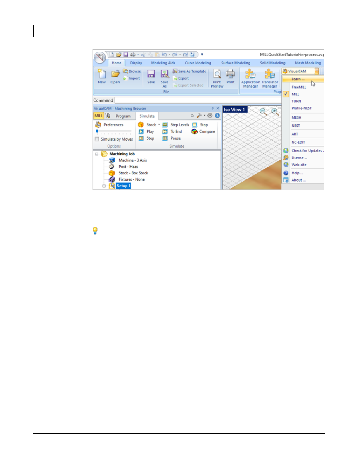
VisualCAD/CAM-MILL 2024 Reference21
To access the Learning Resources dilog in VisualCAM
2. Select a document from the Learning Resources dialog to get started using the
module of your choice.
You can also select the Open Quick Start Files Folder button located at the bottom
of the dialog to open the Quick Start folder where the source files (start and
completed versions) are located.
© 2024 MecSoft Corporation
Page 23
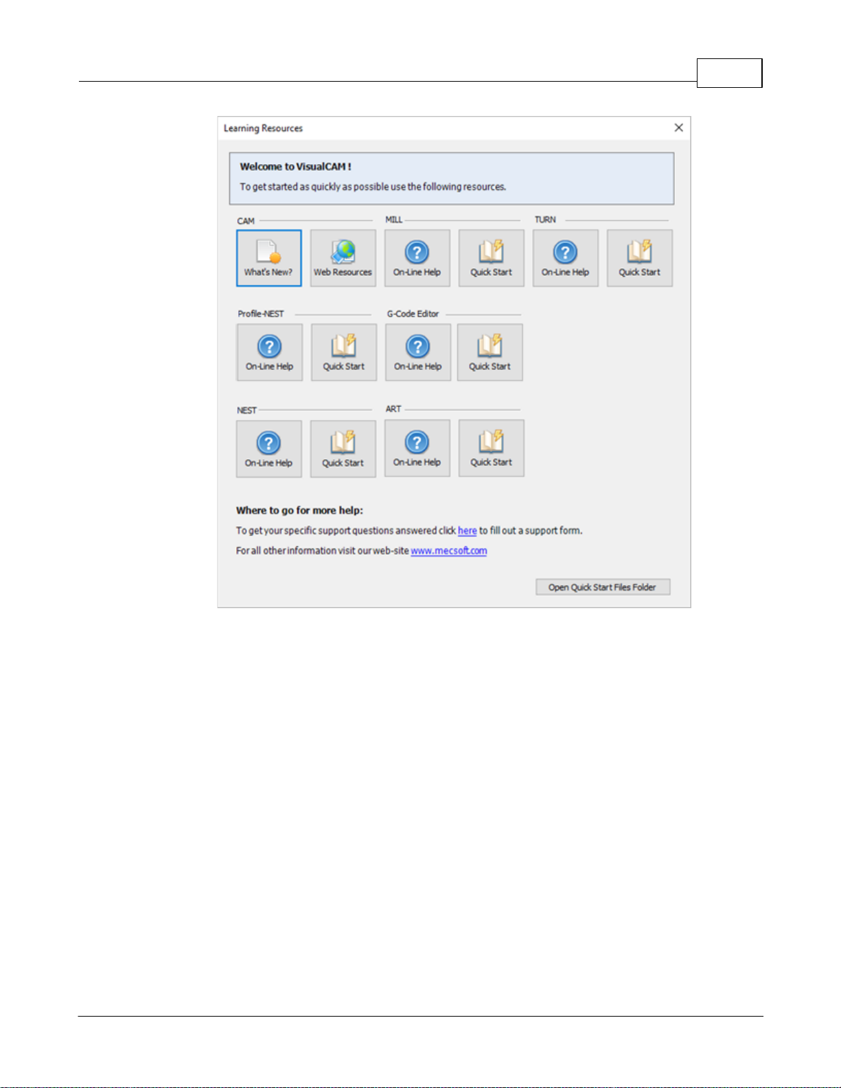
Quick Start 22
Learning Resources Dialog
© 2024 MecSoft Corporation
Page 24
VisualCAD/CAM-MILL 2024 Reference23
The 2024 VisualCAM Resource Guide!
18 Pages
Lists PDF downloads and Online resources including Quick Start
Guides, Reference Guides, Exercise Guides, Tutorials and
More.
Prefer Printed Documentation? Click Here!
Resource Guide
Download this PDF Guide for a list of the available VisualCAM Resources.
2024 VisualCAM Resource Guide
© 2024 MecSoft Corporation
Page 25
Welcome
The VisualCAM-MILL module offers fast gouge free solids/surface model machining technology
coupled with cutting simulation/verification capabilities running inside VisualCAM. This
integration allows for seamless generation of toolpath and cut material simulation/verification
inside VisualCAM, for programming milling machines that support 3, 4 & 5 axis continuous and
indexed machining.
Welcome 24
MILL Module 2024
Prefer Printed Documentation? Click Here!
For purposes of brevity, VisualCAM-MILL will be referred to as MILL in all subsequent references.
The MILL module also comes with numerous post-processors to output the programmed G-code to
some of the most popular machines in the market. A simple and well thought out user interface
makes this system one of the most intuitive and easy to use milling systems on the market. This
online help system provides comprehensive help topics as well as context sensitive help to help
you become a productive user of VisualCAM.
3.1 Overview
The VisualCAM MILL module offers fast gouge free solids/surface model machining technology
coupled with cutting simulation/verification capabilities running on standard Windows hardware.
These features take the uncertainty out of the toolpath programming process and allow you to
produce toolpaths that you can send to the machine tool with utmost confidence. A simple and
well thought out user interface makes this system one of the most intuitive and easy to use
milling systems in the market. This feature makes RhinoCAM suitable to be deployed in the shop
floor to work in conjunction with your existing CAD/CAM system.
The VisualCAM MILL module supports milling operations from simple 2½ axis milling to
continuous 5 axis milling. Additionally drilling operations are supported in all of these axes as
well. Most of the popular milling machine tool controllers are supported out of the box.
Additionally the MILL module also includes a post-processor generator product that can be used to
tailor the output to virtually any machine tool controller in the market.
On-line help compiled on: Monday, May 13, 2024
© 2024 MecSoft Corporation
Page 26
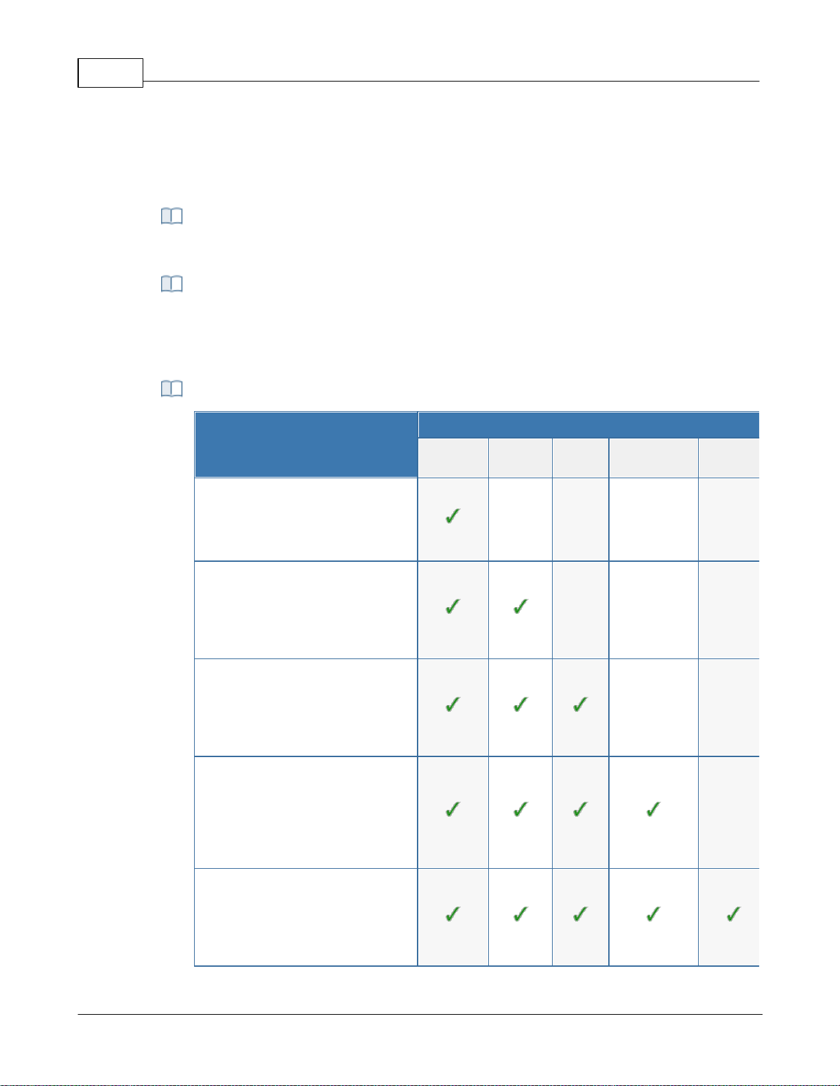
VisualCAD/CAM-MILL 2024 Reference25
VisualCAM can be easily upgraded from one configuration to another. When you
purchase a configuration upgrade, your new activation code will enable the additional
functionality automatically.
Summary of
MILL Configurations
Configuration
Xpress
(XPR)
Standard
(STD)
Expert
(EXP)
Professional
(PRO)
Premium
(PRE)
Xpress (XPR):
Limi ted 2 & 3 Axis toolpath strategies ,
Tool creation, Bas ic Simul ati on,
Tool path Graphica l Viewing, Post
Process ing & more...
Standard (STD):
More 2 Axis toolpaths , li mited 3 Axis
toolpa ths, more Tools and Tool
librarie s, Advanced Simul ation,
Tool path Graphica l Viewing, Post
Process ing & more...
Expert (EXP):
Most 2 Axis tool paths, l imited 3 Axis
toolpa ths, 4 Axis toolpa ths, more Tool s
and tool li braries, Advanced
Simulati on, Tool path Gra phical
Viewing, Pos t Proce ssi ng & more...
Professional (PRO):
All 2 Axis & Advanced 3 Axis tool paths,
4 Axis tool paths, i ndexed 5 Axis
toolpa ths, a ll Tool types & l ibraries ,
Advanced Simul ation, Toolpath
Graphical Editi ng, Post Process ing &
more...
Premium (PRE):
All 2 Axis & Advanced 3 axis toolpaths,
all 4 & 5 Axis toolpa ths, all Tool type s
& libraries, Advanced Simul ation,
Tool path Graphica l Edi ting, Pos t
Process ing & more...
3.2 Configurations
In this topic you will find an overview of the features in the VisualCAM MILL module:
Data Import
MILL Configuration Upgrades
Summary of MILL Configurations
© 2024 MecSoft Corporation
Page 27
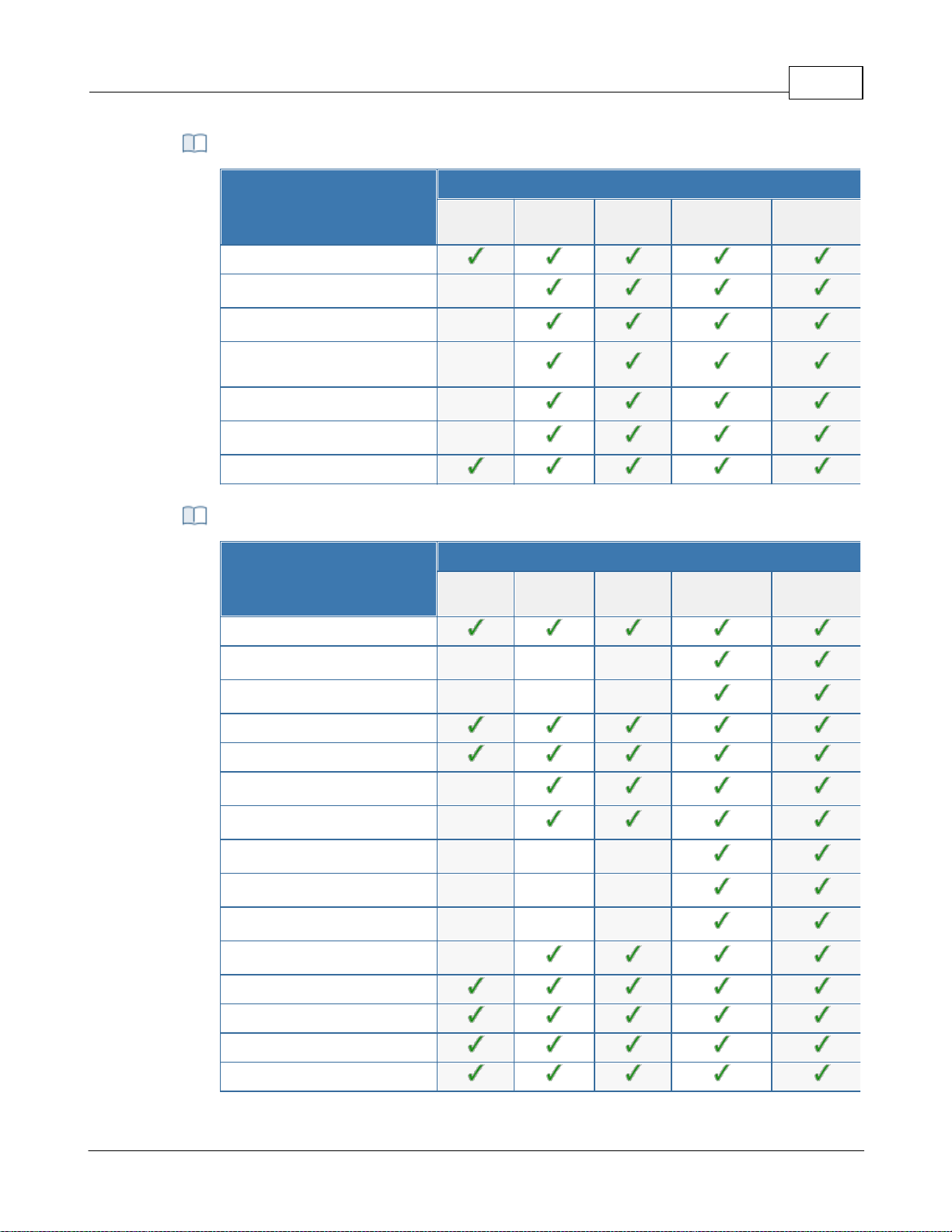
Common Features
Common
Configuration
Xpress
(XPR)
Standard
(STD)
Expert
(EXP)
Professional
(PRO)
Premium
(PRE)
64 Bit
Saving Toolpath Defaults
Predefined Regions Creation
Drag/Drop Tools and Knowledge
Bases
Avoid Regions
Manual Tabs/Bridges Creation
Stepped Tooling
Setup & Stock
Configuration
Xpress
(XPR)
Standard
(STD)
Expert
(EXP)
Professional
(PRO)
Premium
(PRE)
Orient Part
Multiple Coordinate System Setups
Rotate Table Setups
Box Stock
Part Box Stock
Cylinder Stock
Part Cylinder Stock
Part Offset Stock
Extruded Stock
Stock from Selection
Export Stock to STL
Delete Stock
Align Stock
Set World CS
Set Stock Material
Setup & Stock Features
Welcome 26
© 2024 MecSoft Corporation
Page 28
VisualCAD/CAM-MILL 2024 Reference27
Set Work Zero
2½ Axis
Machining
Configuration
Xpress
(XPR)
Standard
(STD)
Expert
(EXP)
Professional
(PRO)
Premium
(PRE)
Face Top
Roughing
Facing
Pocketing
High Speed Pocketing
Profiling
V-Carve Roughing
V-Carve Finishing
Engraving
Slotting
Chamfering
Filleting
Hole Pocketing
Hole Profiling
Thread Milling
T-Slot Machining
Knife Cutting
Saw Machining
Re-Machining
Hole
Machining
Configuration
Xpress
(XPR)
Standard
(STD)
Expert
(EXP)
Professional
(PRO)
Premium
(PRE)
Automatic Hole Selection, Sorting
Drilling
2½ Axis Machining Features
Hole Machining Features
© 2024 MecSoft Corporation
Page 29
Tapping
Boring
Reverse Boring
User Defined Drill Cycles
3 Axis Milling Features
3 Axis
Milling
Configuration
Xpress
(XPR)
Standard
(STD)
Expert
(EXP)
Professional
(PRO)
Premium
(PRE)
Adaptive Roughing
Horizontal Roughing
Plunge Roughing
Horizontal Re-Roughing
Plunge Re-Roughing
Clear Flats
Parallel Finishing
Horizontal Finishing
Projection Pocketing
3D Offset Pocketing
3D Offset Profiling
Pencil Tracing
Valley Machining
Flats Machining
Steeps Machining
Steeps Z Finishing
Radial Machining
Spiral Machining
Curve Machining
Between 2 Curves Machining
Reverse Post Machining
Welcome 28
© 2024 MecSoft Corporation
Page 30
VisualCAD/CAM-MILL 2024 Reference29
Flat Regions
Silhouette Regions
Valley Regions
Check Regions
Collision Regions
4 Axis
Machining
Configuration
Xpress
(XPR)
Standard
(STD)
Expert
(EXP)
Professional
(PRO)
Premium
(PRE)
4 Axis Create Round
4 Axis Facing
4 Axis Pocketing
4 Axis Profiling
4 Axis L-Level Roughing
4 Axis R-Level Finishing
4 Axis Parallel Finishing
4 Axis Projection Pocketing
4 Axis Engraving
4 Axis Drive Surface
4 Axis Drilling
4 Axis Tapping
4 Axis Boring
4 Axis Reverse Boring
5 Axis
Machining
Configuration
Xpress
(XPR)
Standard
(STD)
Expert
(EXP)
Professional
(PRO)
Premium
(PRE)
Indexed 5 Axis (3+2)
5 Axis Curve Projection
4 Axis Machining Features
5 Axis Machining Features
© 2024 MecSoft Corporation
Page 31
5 Axis Flow Curve
5 Axis Between 2 Curves
5 Axis Drive Curve
5 Axis Surface Normal
5 Axis Swarf Machining
Post in 4 Axis Mode
Tool Types
Tool
Types
Configuration
Xpress
(XPR)
Standard
(STD)
Expert
(EXP)
Professional
(PRO)
Premium
(PRE)
Ball Mills
Flat Mills
Corner Radius Mills
Vee Mills
Chamfer Mills
Taper Mills
Threaded Mills
Face Mills
Dovetail Cutters
Fillet Mills
Lollypop Cutters
User Defined Cutters
Drills
Center Drills
Reamers
Taps
Bore Tool
Reverse Bore Tool
Drag Knife Tool
Welcome 30
© 2024 MecSoft Corporation
Page 32
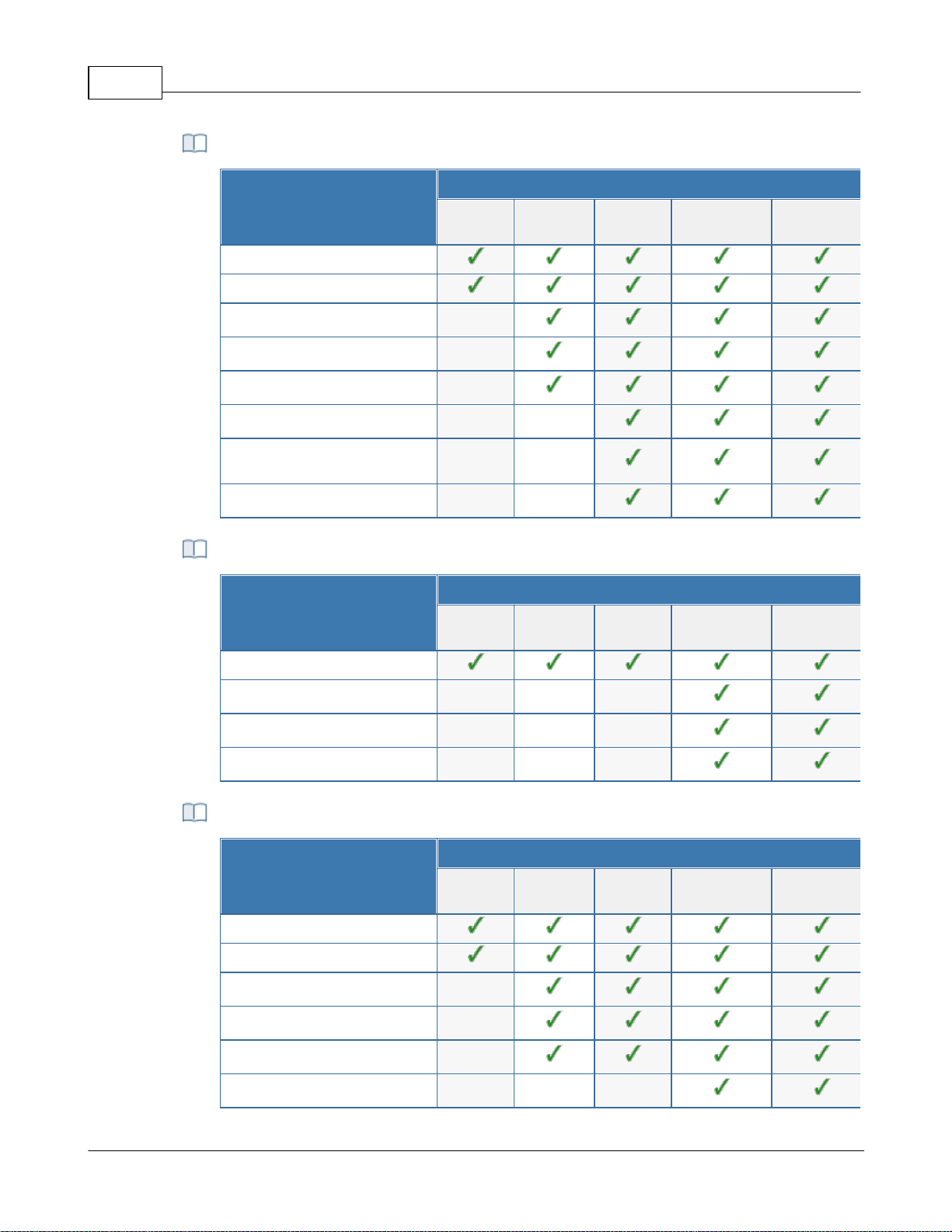
VisualCAD/CAM-MILL 2024 Reference31
Toolpath Editing
Configuration
Xpress
(XPR)
Standard
(STD)
Expert
(EXP)
Professional
(PRO)
Premium
(PRE)
Toolpath Animation
Cut Material Simulation
Advanced Cut Material Simulation
Visual Holder Collision Detection
Visual Tool Shank Collision Detection
Analytical Holder Collision Detection
Analytical Tool Shank Collision
Detection
Machine Tool Simulation
Toolpath Editing
Configuration
Xpress
(XPR)
Standard
(STD)
Expert
(EXP)
Professional
(PRO)
Premium
(PRE)
Toolpath Graphical Viewing
Toolpath Graphical Editing
Toolpath Instancing
Toolpath Arc Fitting
Post Processor
Generator
Configuration
Xpress
(XPR)
Standard
(STD)
Expert
(EXP)
Professional
(PRO)
Premium
(PRE)
Customizable Post Generator
Simulate Cycles
Arc Output
Helix Output
Spiral Output
5 Axis Output
Simulation Features
Toolpath Editing Features
Post Processor Generator Features
© 2024 MecSoft Corporation
Page 33
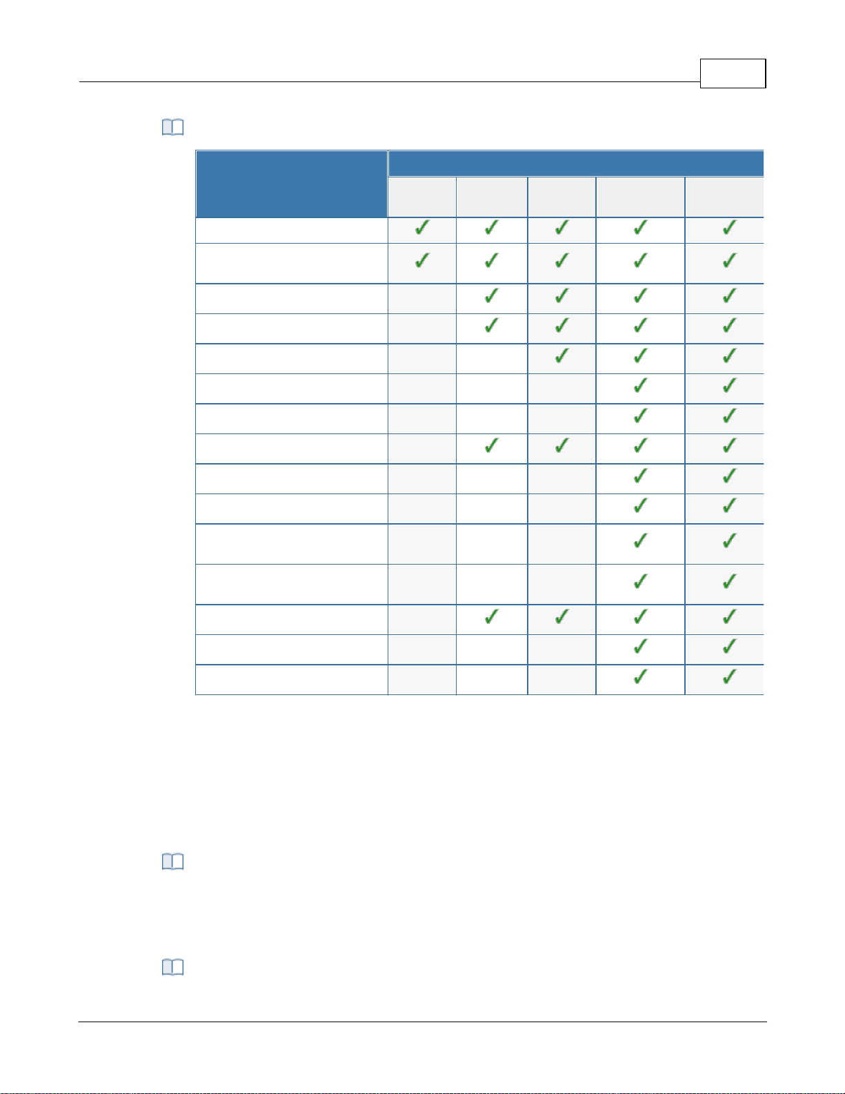
Other Features
Other
Features
Configuration
Xpress
(XPR)
Standard
(STD)
Expert
(EXP)
Professional
(PRO)
Premium
(PRE)
HTML Based Shop Documentation
Automatic Bridges & Tabs in 2½ Axis
Profiling
Knowledge Base
Cabinet Design Decomposition
Rotate Table Setups
Multiple Setups
Fixture Offset Programming
Machine Control Operations
Check Surface Boundary Creation
Tool Silhouette Boundary Creation
Tool Double Contact Boundary
Creation
Tool Holder Collision Boundary
Creation
Feature Based Machining
Backplot Toolptahs
Toolpath Diagnostics
A typical machining strategy employed in the manufacturing industry is to use larger
cutters to perform bulk removal of material early on in the manufacturing process. These
operations are called roughing operations.
Welcome 32
3.3 Understanding
The manufacturing process aims to successively reduce material from the stock model until it
reaches the final shape of the designed part model. To accomplish this, the machinist or
programmer utilizes a machining strategy.
Roughing Operations
Pre-Finishing Operations
© 2024 MecSoft Corporation
Page 34
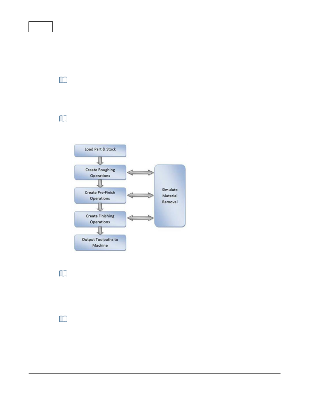
VisualCAD/CAM-MILL 2024 Reference33
This is then followed by operations employing successively smaller cutters removing
proportionately smaller amounts of material from the stock model. This is done until the
part has a uniform amount of stock left. These operations are called pre-finishing
operations.
This is then followed by finish operations. Here the uniform stock remaining on the part
is removed by using a small cutter removing a constant amount of material with every
motion to produce the net shape.
The standard work-flow of MILL module mimics this process and can be represented by
the flow chart shown below.
The work-flow of the MILL module mimics the standard production
process of material removal
Part geometry is imported into the VisualCAM MILL module via the various data
interfaces provided in VisualCAD. A stock model representing the raw stock from which
the part needs to be manufactured can then either be created using the various tools
provided in the MILL module or imported.
You then determine the machining strategy to be used in manufacturing the part. This
can be done by loading a previously saved manufacturing operation sequence or by
creating a new one. This manufacturing strategy is represented by a sequence of
machining operations in the MILL module.
Finishing Operations
Standard MILL Module Work-flow
Part Geometry
Typical Machining Strategy
© 2024 MecSoft Corporation
Page 35

Welcome 34
To create a new machining strategy, simply select the tools and the machining
operations in sequence and then generate toolpaths. The system automatically records
this sequence. This record can be archived as an operation list that can be retrieved for
later use.
Here is a typical machining strategy:
1. To create a new machining operation, select a tool followed by the type of
toolpath to be created. You set the parameters to use for machining and
generate the toolpath.
2. A 3D part is typically machined using 3 axis operations. It can be rough machined
initially by employing a horizontal roughing operation, followed by a finishing
operation. The horizontal roughing toolpath will typically be generated using a
relatively large flat end mill or an end mill with a corner radius to efficiently
remove bulk of the material from the raw stock. This machining operation could
be followed up with another horizontal roughing operation either with the same
tool or with a smaller tool to remove more material.
3. The part can then be pre-finished by employing either the parallel finishing
operation or the horizontal finishing operation. Pre-finishing and finishing
operations typically employ ball end mills with or without a side angle.
4. Finally a parallel finishing operation using a small radius ball tool and employing
a fine step-over is then used to finish the part to net-shape. This may or may not
be followed by other re-finishing operations to reduce handwork on the part.
For prismatic parts that have straight walls, it might be more expedient to use 2-1/2 axis
toolpath methods rather than the 3 axis methods described above. The strategy
followed however will be similar where in bulk material removal or roughing will be
performed by a combination of facing and pocketing operations. These will then be
followed up with one or more profile finishing operations. It should be noted that for 21/2 axis operations it is not necessary to have the complete 3D geometry defined.
Curves that represent the sides of the part are sufficient to define the geometry for
machining.
Once all of the operations are completed you can then go back and review the operation
sequence, perform Tool and Cut Material Removal Simulations, re-order operations if
desired and output the toolpath for post-processing. The Machining Browser can be used
to manage these operations.
For Prismatic Parts
Review, Manage and Post Process
3.4 Work flow
© 2024 MecSoft Corporation
Once the part is loaded, the typical work-flow is reflected in the layout of the tabs of the
Machining Operations (Mops) Browser window. The work-flow is designed to allow you to work
starting from the left most tab and ending at the right most tab. As each tab is accessed, a ribbon
Page 36
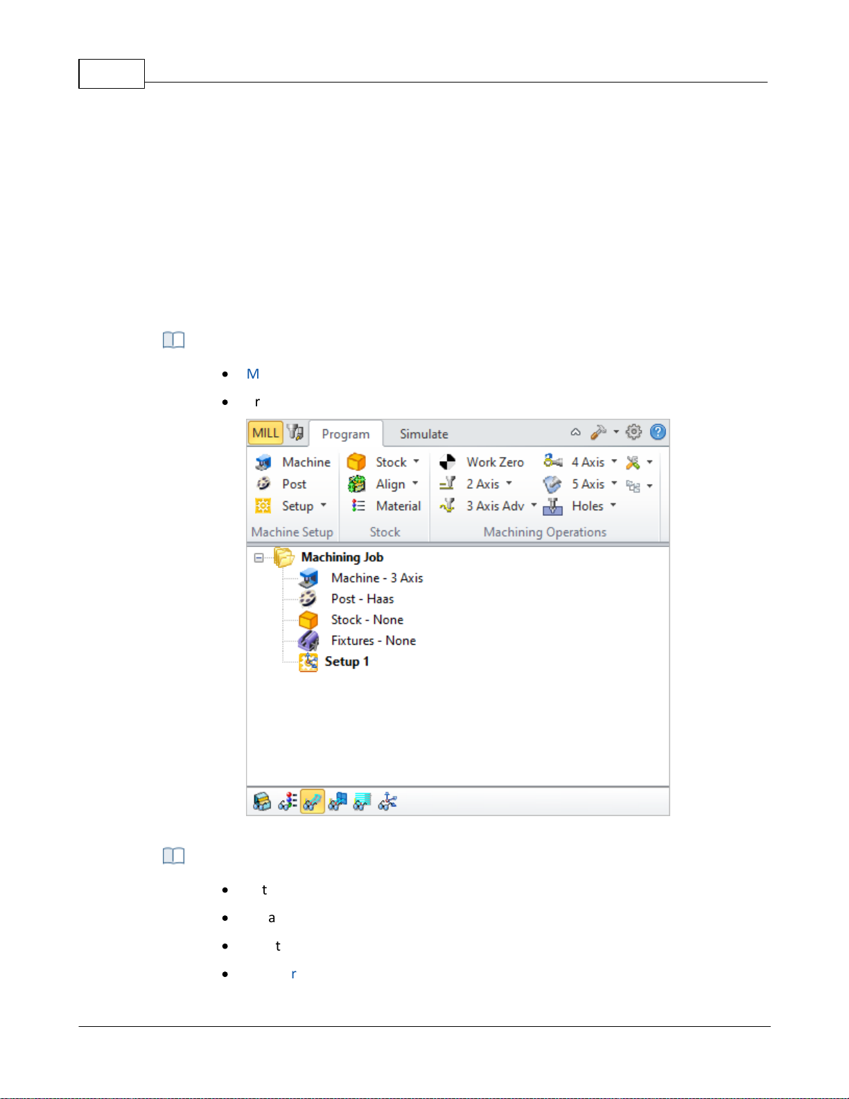
VisualCAD/CAM-MILL 2024 Reference35
·
Machine Setup and define Stock before programming
·
Create Machining Operations
Program tab of the Machining Operations Browser (MOps)
·
Set Simulation Preferences
·
Create Tool Simulations
·
Create Cut Material Simulations
·
Compare and Create 3D Stock Models
toolbar with functions specific to the tab chosen will be displayed just below the tab. The
functions in each of the toolbars corresponding to each tab are also best accessed in order from
left to right.
Thus you typically would start with the Program tab and access each of the buttons, optionally, in
the toolbar that appears when this tab is selected in sequence from left to right. Once the setup
functions are completed, you will then proceed to the Machining Operations group to commence
programming the part. Once machining operations are completed you can simulate the
operations by selecting the Simulate tab before finally sending the operation codes to the
machine tool.
Step 1: Program Tab
Step 2: Simulate Tab
© 2024 MecSoft Corporation
Page 37
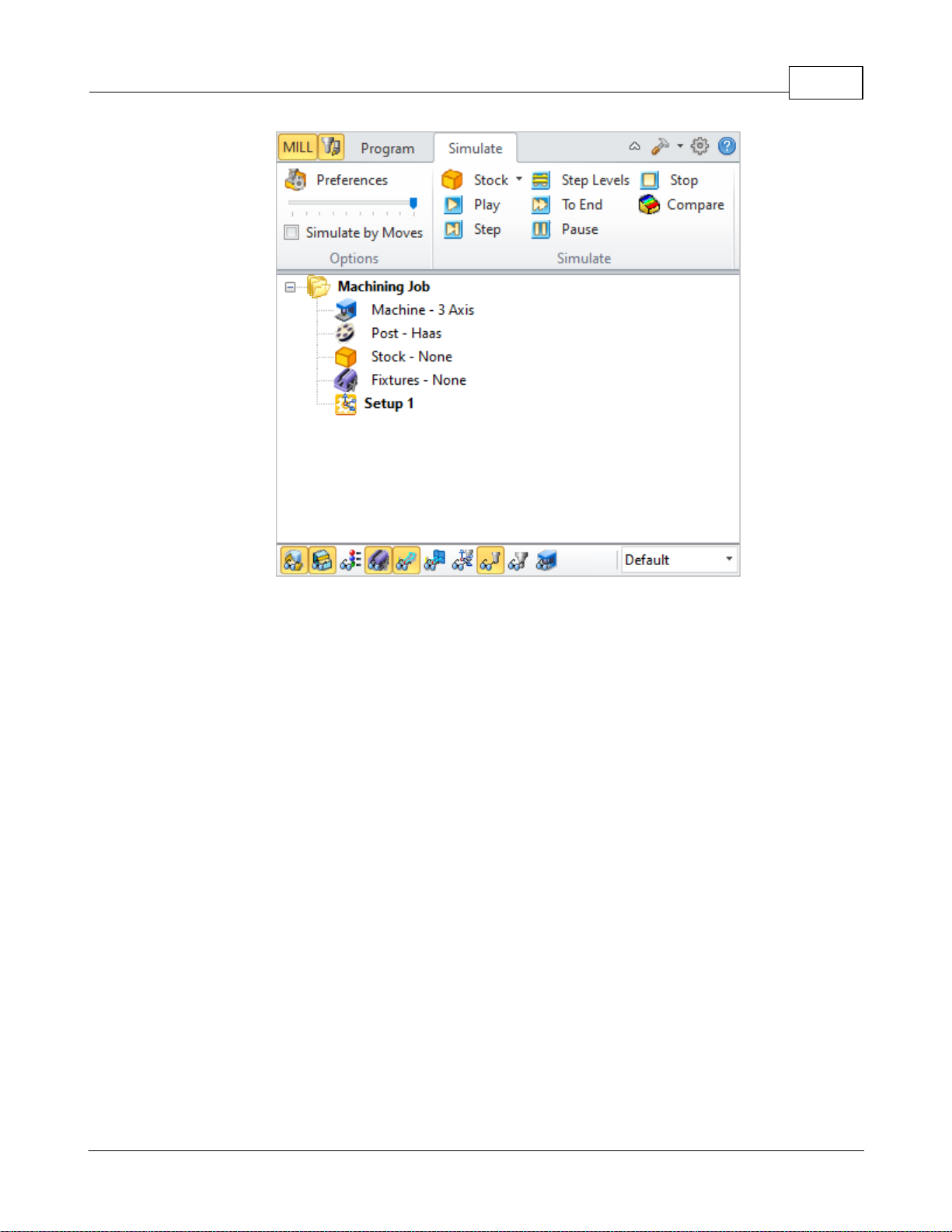
Welcome 36
Simulate tab of the Machining Operations Browser (MOps)
3.5 Post-Processing
Once the machining operations have been created and verified, they can be post processed to
create G-code files. These G-code files can then be sent to the controller of the machine tool to
drive the actual machine tool.
© 2024 MecSoft Corporation
Page 38
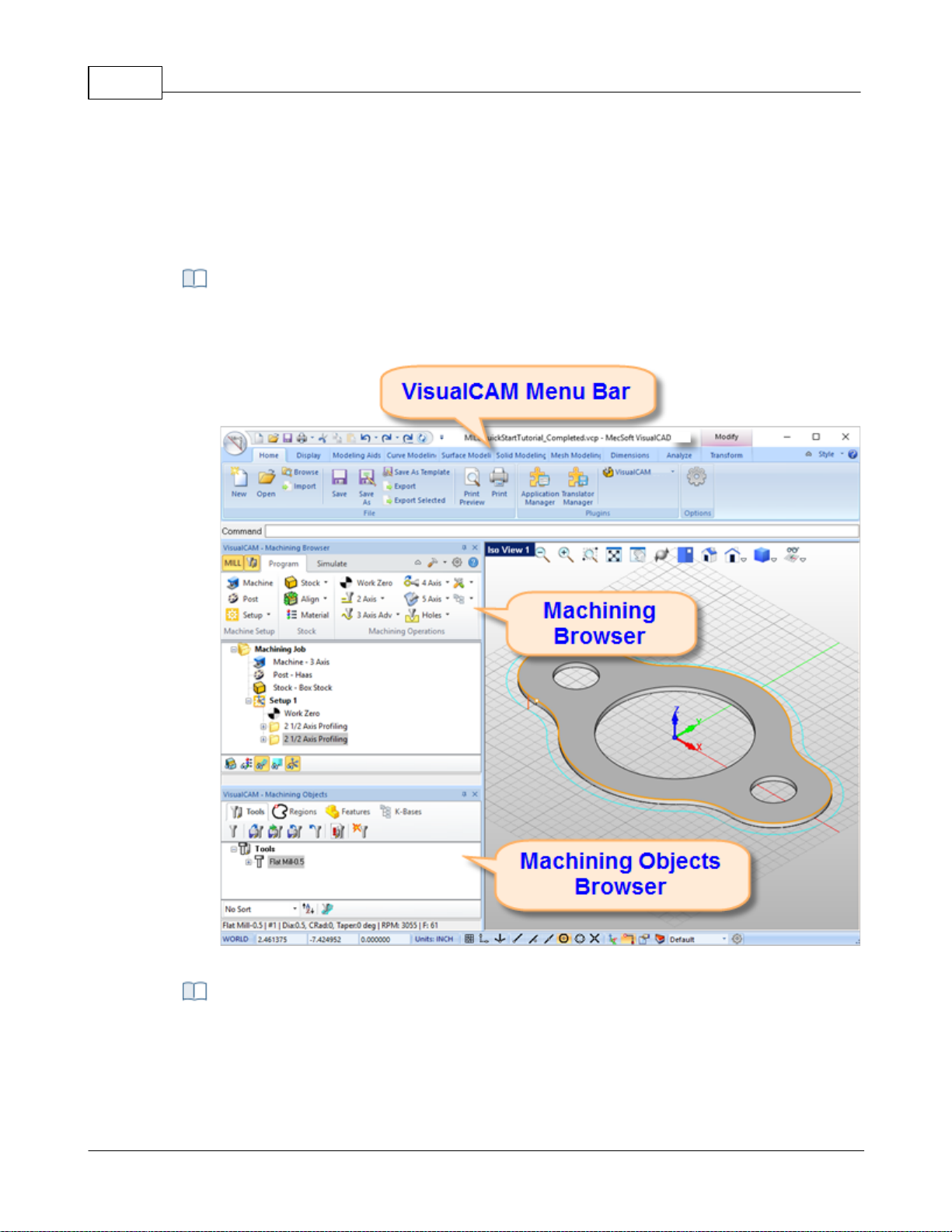
VisualCAD/CAM-MILL 2024 Reference37
A screen shot of the VisualCAM MILL module running inside of VisualCAD is shown
below:
The MILL module running inside of VisualCAD
There are 3 main interface objects created when MILL module is loaded.
1. VisualCAM menu bar entry under VisualCAD menu bar
2. Machining Browser (Mops) window
User Interface
The VisualCAM MILL module adheres to the Windows standard for user interface design and
integrated into the VisualCAD screen seamlessly.
MILL Module Displayed
The VisualCAM MILL Interface
© 2024 MecSoft Corporation
Page 39
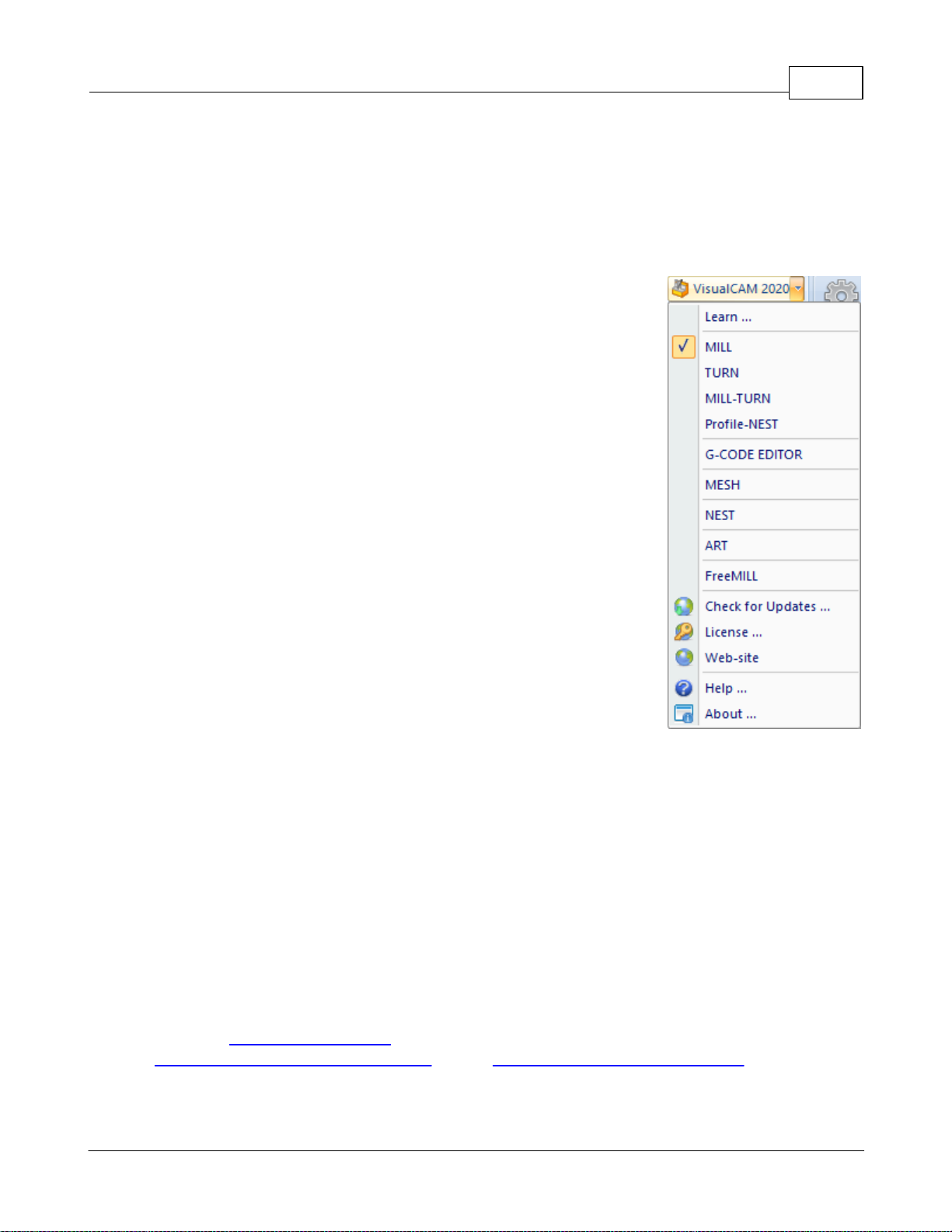
3. Machining Objects (Mobs) Browser window
4.1 VisualCAM Menu Item
VisualCAM menu Item
When VisualCAM is loaded a menu item is added to the Plugins Pane of the Home Ribbon Bar.
Selecting this item will display a drop down menu as shown below.
To run MILL module, select MILL from the VisualCAM 2024 drop down
menu.
Selecting MILL toggles the display of the Milling Browser window from
the VisualCAD user interface. If the FreeMILL, TURN, NEST or ART
Browser is currently open selecting this will switch the display to the
MILL Browser.
User Interface 38
4.2 MILL Browsers
The MILL Browser is a dock-able window that allows management of various entities or objects
that can be created in the VisualCAM MILL module. There are 2 browsers in VisualCAM –
Machining Operations Browser (Mops) and Machining Objects Browser (Mobs).
4.3 Machining Browser
The Machining Browser, sometimes called the Machining Operations (Mops) Browser, has two
main modes of operation represented by tabs at the top of the window. These are Program and
Simulate. Each tabbed view also incorporates a ribbon toolbar at the top. These toolbars group all
of the functions associated with the type of object in the tab.
Note: See Right-Click Commands for a complete list of all right-click commands available from the
Machining Operations (Mops) Browser and the Machining Objects (Mobs) Browser.
© 2024 MecSoft Corporation
Page 40
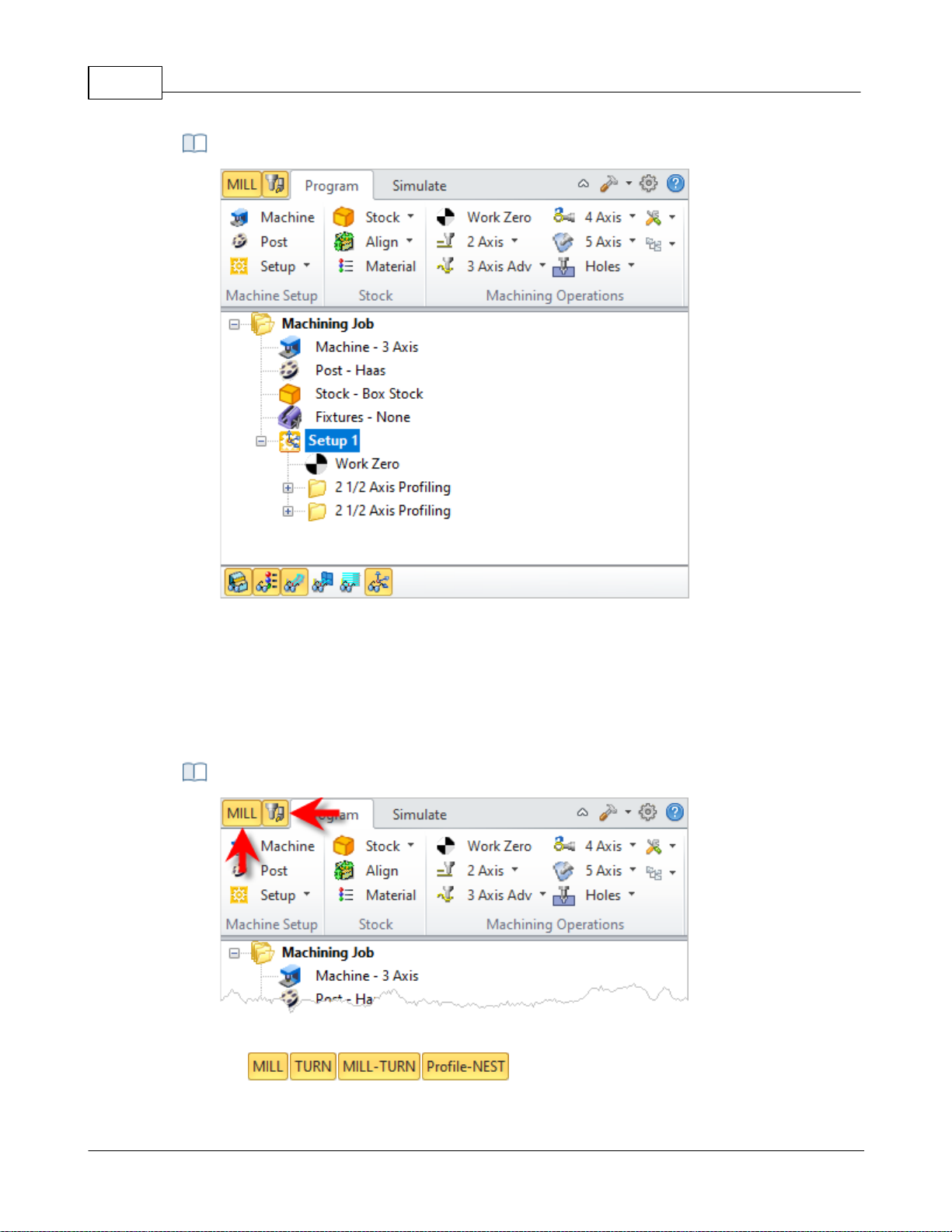
VisualCAD/CAM-MILL 2024 Reference39
The Machining Operations (MOps) Browser, Program Tab
Locating the Brow ser Toggle Tabs
The Machining Operations (Mops) Browser
4.3.1 Browser Toggle Tabs
Tabs available on the Machining Browser that allow you to toggle the display of both the
Machining Browser and the Machining Objects Browser.
Browser Toggle Tabs
© 2024 MecSoft Corporation
Page 41
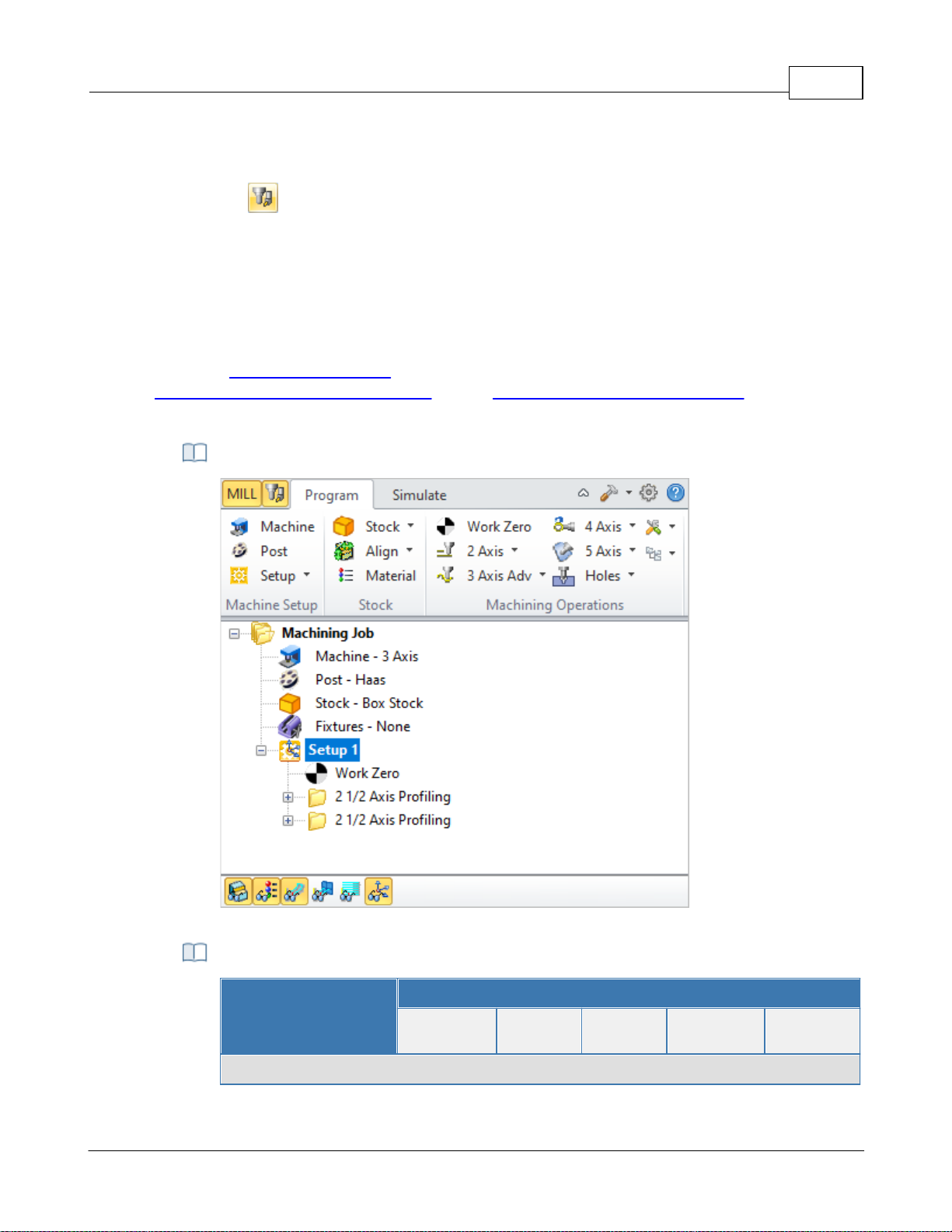
Selecting this tab toggles between the MILL , TURN, MILL-TURN and Profile-NEST
Machining Browser.
Select this tab to toggle the display of the Machining Objects Browser.
4.3.2 Program Tab
The Machining Operations (MOps) Browser, Program Tab
Summary
Available Configuration
Xpress
(XPR)
Standard
(STD)
Expert
(EXP)
Professional
(PRO)
Premium
(PRE)
Machine Setup Pane
Selecting the Program tab in the Mops Browser provides access for specifying Machine, Stock and
the definition of Machining Operations.
Note: See Right-Click Commands for a complete list of all right-click commands available from the
Machining Operations (Mops) Browser and the Machining Objects (Mobs) Browser.
The Machining Operations (Mops) Browser, Program Tab
User Interface 40
Machine Setup Pane
© 2024 MecSoft Corporation
Page 42
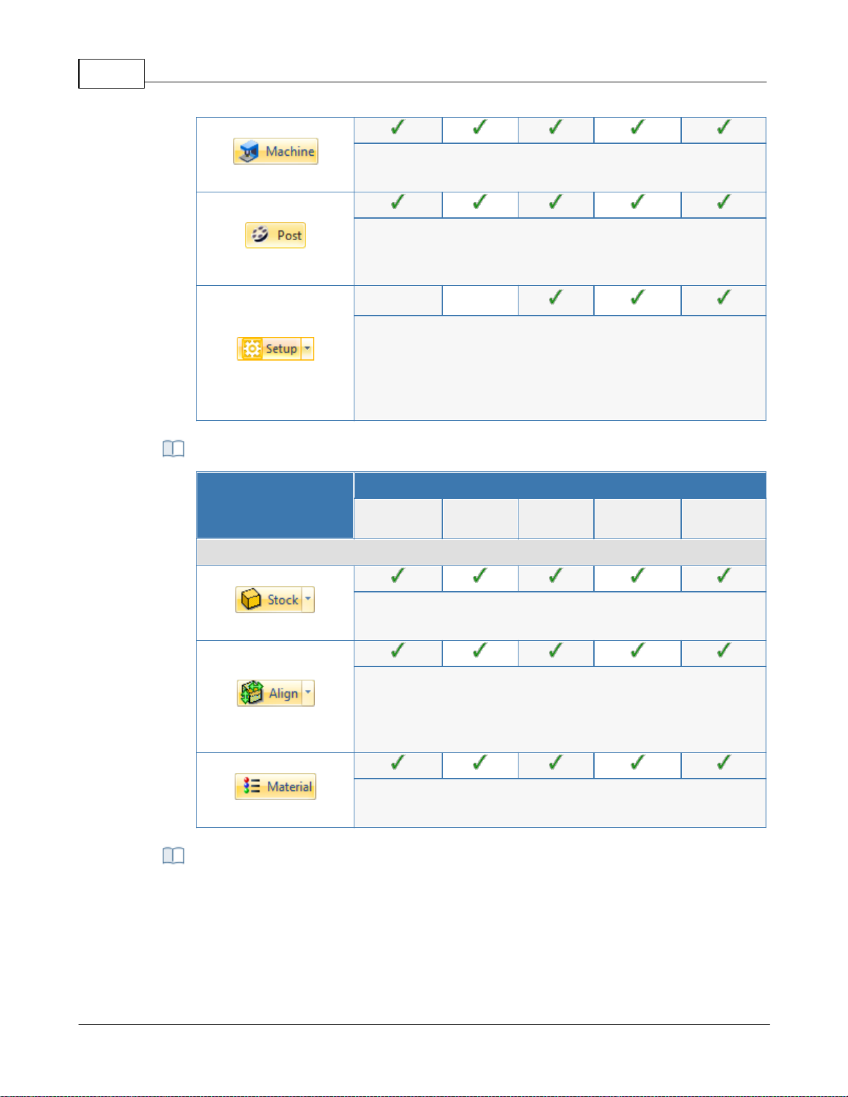
VisualCAD/CAM-MILL 2024 Reference41
Machine Tool Setup: Sets the Machine for 2½ axis, 3 axis, 4 axis
and 5 axis operations.
Set Post-Processor Options: Allows you to set the Current Post
Processor, posted file naming conventions, posted file
extension, program to display the posted file.
Create Setup Operations: Sets the Coordinate System for
Machining. The orientation of the part can be set using Orient
Part, orientation of the Coordinate System can be defined
under Set CSYS Setup for 3+2 machining and Rotate Table Setup
for 4 axis table rotate operations.
Summary
Available Configuration
Xpress
(XPR)
Standard
(STD)
Expert
(EXP)
Professional
(PRO)
Premium
(PRE)
Stock Pane
Create Stock Model: Allows you to create Stock geometry. User
can also delete a Stock geometry by selecting Delete Stock.
Align: Allows you to Align stock model to part and locate WCS
with respect to Part or Stock . This function is especially useful
when the part model and the stock model are created without
regard to their respective positional locations.
Define Stock Material: Allows you to select a material from the
material list.
This section allows you to create machining operations. MILL module allows you to
create multiple machining operations in a part file. This is a powerful feature that allows
you to create an entire sequence of machining operations that is necessary to create the
part model from the stock model. This set of operations can additionally be archived
with the part file and retrieved at a later time with no loss of information.
Stock Pane
Machining Operations Pane
© 2024 MecSoft Corporation
Page 43
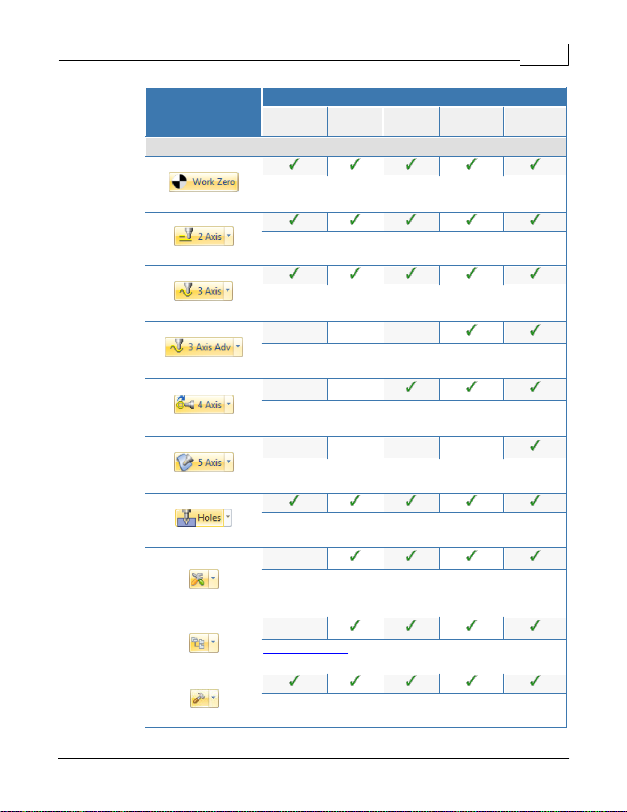
User Interface 42
Summary
Available Configuration
Xpress
(XPR)
Standard
(STD)
Expert
(EXP)
Professional
(PRO)
Premium
(PRE)
Machining Operations Pane
Set Current Work Coordinate Zero: Allows you to set the work
Coordinate zero (Origin) for the part being programmed.
Create 2 ½ Axis Milling Operations: Provides access to 2 ½
Axis Machining Methods.
Create 3 Axis Milling Operations: Provides access to 3 Axis
Machining Methods
Create 3 Axis Advanced Milling Operations: Provides access
to 3 Axis Machining Methods.
Create 4 Axis Milling Operations: Provides access to 4 Axis
Machining Methods
Create 5 Axis Milling Operations: Provides access to 5 Axis
Machining Methods.
Holes: Provides access to Drilling, Tapping, Boring and
Reverse Boring Machining Methods.
Create Miscellaneous Operations: Allows you to create
Machining Operation Sets, Machine Control Cycles, Fixture
Offset and XY Instance operations.
Knowledge Base Operations: Allows saving and loading of
Machining operations to and from a knowledge base.
Utilities: Provides access to G Code Editor and Post
Process Generator.
© 2024 MecSoft Corporation
Page 44
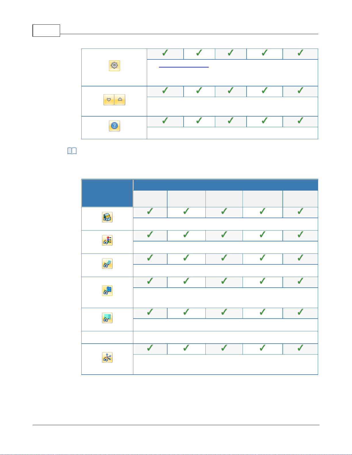
VisualCAD/CAM-MILL 2024 Reference43
Set CAM Preferences: Provides access to specify Color,
User Interface, Machining, Simulation and Feeds Speeds
Preferences.
Minimize/Maximize Ribbon bar: Minimizes & Maximizes the
ribbon bar.
Display Help Content: Open On-line Help document.
This toolbar is located at the base of the Machining Browser and has the following
controls:
Summary
Available Configuration
Xpress
(XPR)
Standard
(STD)
Expert
(EXP)
Professional
(PRO)
Premium
(PRE)
Stock Model Visibility: Turn on/off stock model
Material Texture Visibility: Turn on/off material texture visibility
Toolpath Visibility: Turn on/off toolpath display
Hidden Toolpath Visibility: Turn the hidden portions of toolpaths
on/off.
Display Toolpath Levels: Displays tool path by Z levels
Machine CSYS Visibility: Turns on/off of Machine Coordinate System
display.
Display Toggle Toolbar
© 2024 MecSoft Corporation
Page 45
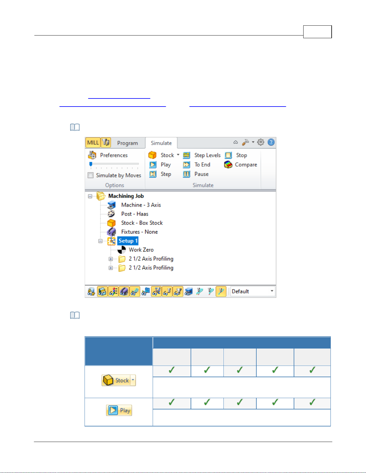
4.3.3 Simulate Tab
The Machining Operations (MOps) Browser, Simulate Tab
The following controls are available on the Simulate tab:
Summary
Available Configuration
Xpress
(XPR)
Standard
(STD)
Expert
(EXP)
Professional
(PRO)
Premium
(PRE)
Create Stock Model: Allows you to create Stock geometry. You
can also delete a Stock geometry by selecting Delete Stock.
Perform Toolpath Simulation or Animation: Allows you to
Select the Simulate tab to run cut material simulations and toolpath animations. This tab also
provides controls to vary the simulation speed, set the simulation preferences and toggle the
display state of various simulation components.
Note: See Right-Click Commands for a complete list of all right-click commands available from the
Machining Operations (Mops) Browser and the Machining Objects (Mobs) Browser.
Machining Operations Browser, Simulate Tab
User Interface 44
Simulate Tab Functions
© 2024 MecSoft Corporation
Page 46
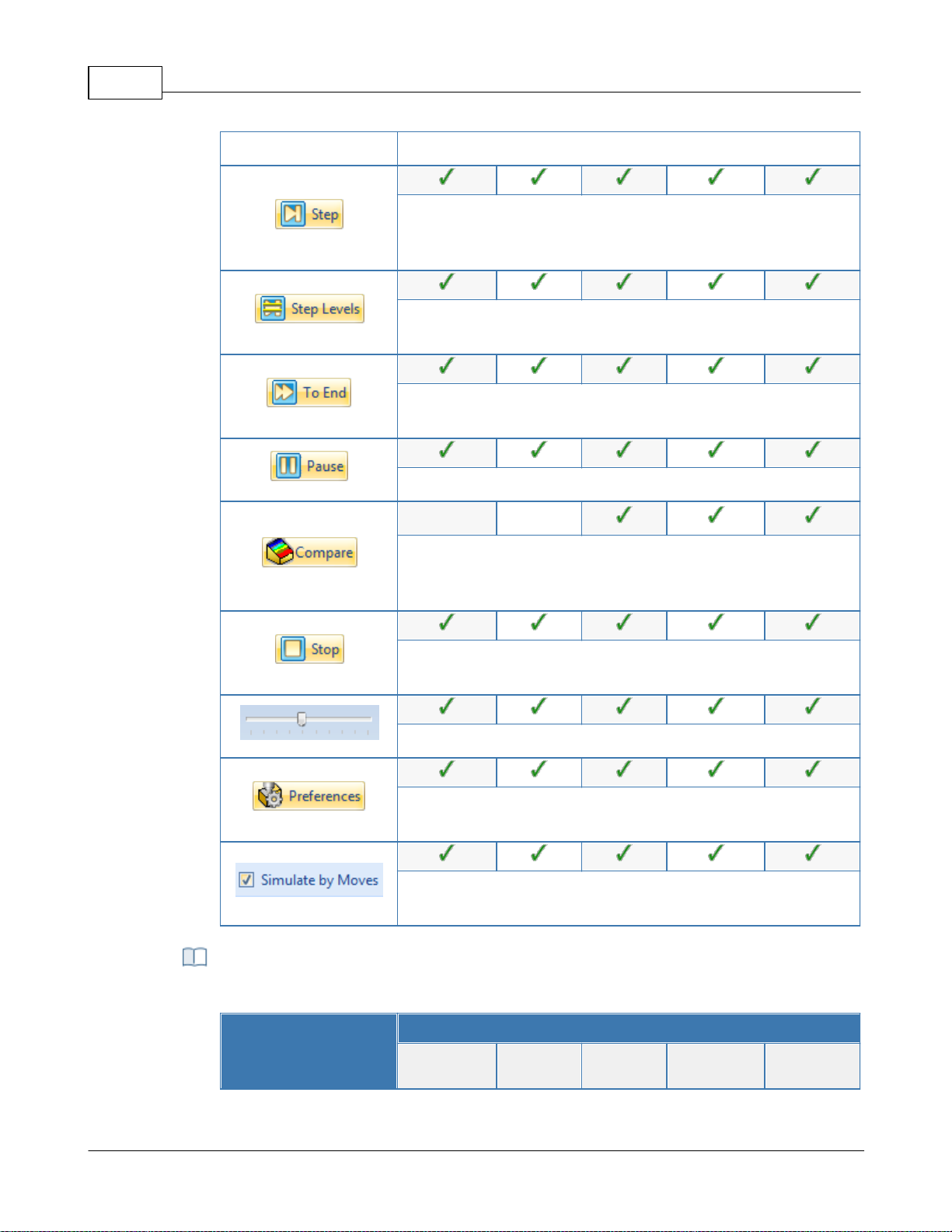
VisualCAD/CAM-MILL 2024 Reference45
perform cut material simulation with tool animation.
Simulate Next Toolpath Block: Simulation is performed in steps
as defined by the display interval in the simulation
preferences.
Simulate Next Toolpath Z Levels: Simulation is performed in
separate Z levels.
Simulate to End: Simulation is performed without updating the
display until the end of the toolpath.
Pause Toolpath Simulation: Pause/Stop the simulation.
Part Stock Compare*: Compare the simulated model with the
part geometry. The part geometry must contain
surface/solid/mesh geometry.
Stop Toolpath Simulation: Exits Simulation Mode. Pause
simulation before exiting simulation mode.
Simulation Speed: Varies simulation speed
Set Simulation Preferences: Provides access to simulation
preferences.
Simulate by Moves: Switches from Simulate by Distance to
Simulate by Motions.
The following toolbar controls are available on the Simulate tab:
Summary
Available Configuration
Xpress
(XPR)
Standard
(STD)
Expert
(EXP)
Professional
(PRO)
Premium
(PRE)
Simulate Toolbar Functions
© 2024 MecSoft Corporation
Page 47
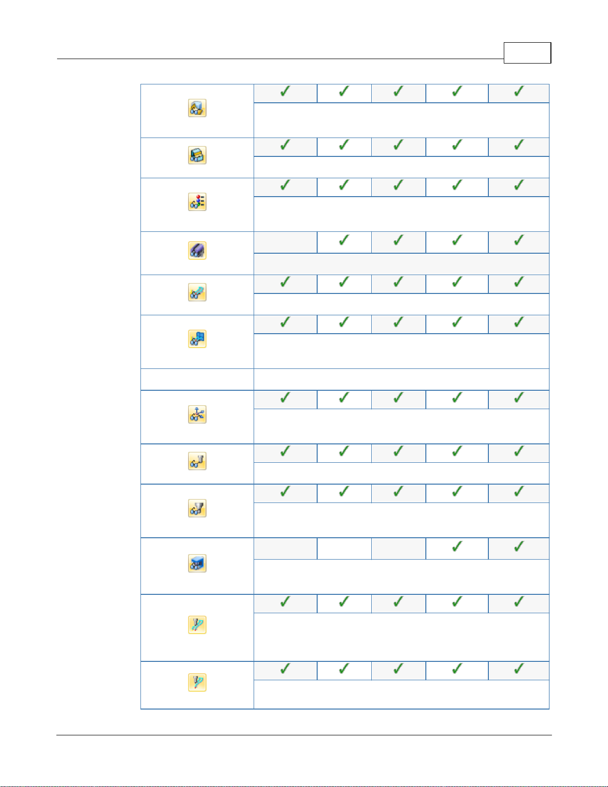
User Interface 46
Part Model Visibility: Turn on/off part model display during
simulation.
Stock Model Visibility: Turn on/off stock model
Material Texture Visibility: Turn on/off material texture
visibility
-
Fixture Model Visibility: Turn on/off stock model
Toolpath Visibility: Turn on/off toolpath display
Hidden Toolpath Visibility: Turn the hidden portions of
toolpaths on/off.
Machine CSYS Visibility: Turns on/off of Machine Coordinate
System display.
Tool Visibility: Turn on/off tool display during simulation.
Holder Visibility: Turn on/off tool holder display during
simulation
---
Machine Tool Visibility**: Turn on/off machine tool display
during simulation
Follow Toolpath Display: The toolpath is displayed as it follows
the behind the movement of the tool (i.e., you will only see the
toolpath after the tool passes.
Trace Toolpath Display: The toolpath is not displayed as it
© 2024 MecSoft Corporation
Page 48
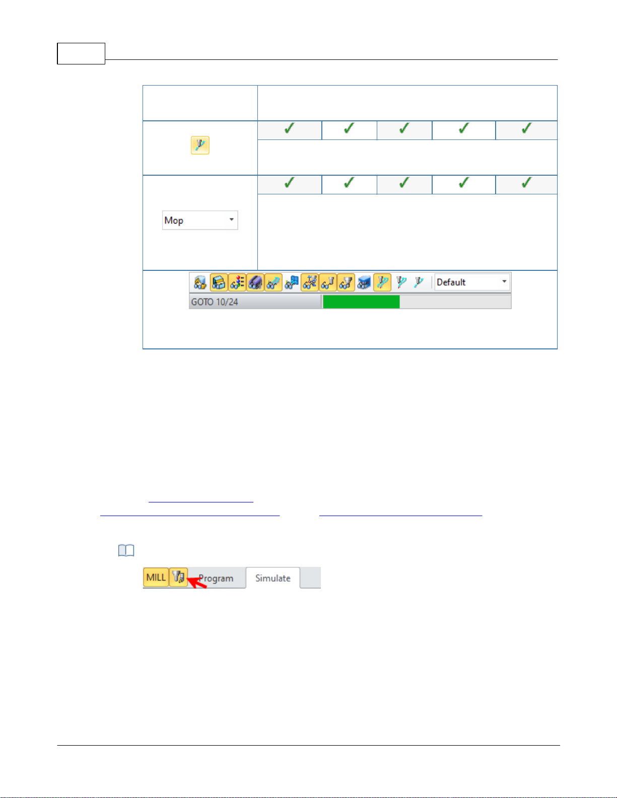
VisualCAD/CAM-MILL 2024 Reference47
follows the behind the movement of the tool (i.e., you will only
see the toolpath before the tool passes.
Segment Toolpath Display: The toolpath is only displayed for
the segment that the tool is currently on.
Simulation Display State: Use this to select the display state for
the simulation. Select from Default, Tool, Mop or Texture. See
Machining Operation Properties for setting unique simulation
colors for each Mop (Machining Operation) in your Machining
Job.
The status bar displays the number of Goto motions of the currently simulated
operation.
Locating the Machining Objects Browser toggle tab
4.4 Machining Objects (Mobs) Browser
The Machining Objects Browser has multiple tabs located at the top to work with different types
of machining objects such as Tools, Regions, K-Bases, etc. Each tabbed view also incorporates a
toolbar at the top. The toolbars on each tab group all of the functions associated with the type of
object in the tab.
The Machining Objects Browser can be toggled on and off by selecting the toggle button located at
the top left corner of the Machining Browser. This toggle button is shown below.
Note: See Right-Click Commands for a complete list of all right-click commands available from the
Machining Operations (Mops) Browser and the Machining Objects (Mobs) Browser.
The Machining Objects (Mobs) Browser
© 2024 MecSoft Corporation
Page 49
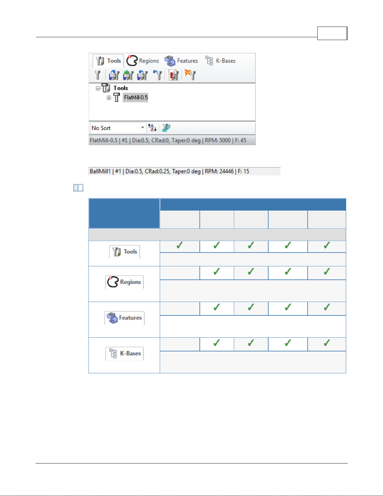
The Machining Objects (MObs) Browser
The status bar displays the currently selected tool, spindle speed and cut feedrate.
Machining Objects Browser Tabs
Summary
Available Configuration
Xpress
(XPR)
Standard
(STD)
Expert
(EXP)
Professional
(PRO)
Premium
(PRE)
Machining Operations Pane
Tools tab: Allows you to create, edit, tools and tool libraries.
Regions tab: Allows you to create and edit pre-define regions
for use with machining operations.
Features tab: Allows you to detect machinable features and
perform automatic and interactive feature machining.
K-Bases tab: Allows you to load, edit and save machining
knowledge bases.
User Interface 48
4.4.1 Tools Tab
Selecting the Tools tab under the Machining Objects Browser brings up the tool manager. The tool
manager lists all of the tools currently defined as well as the tools that are in use in machining
operations. Users can edit a tool by double clicking the tool button in the browser. A tool can be
deleted by selecting the tool from the Tools browser, right click cut or use the delete key from the
keyboard.
© 2024 MecSoft Corporation
Page 50
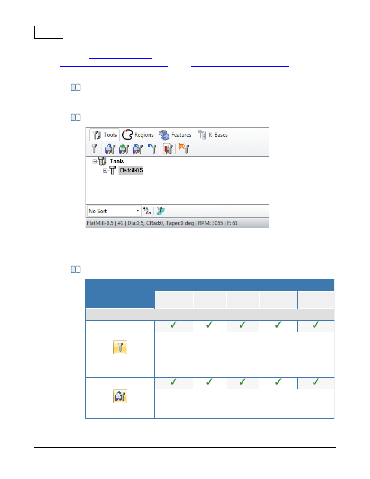
VisualCAD/CAM-MILL 2024 Reference49
There are right-click commands available for use in the Tools tab.
The Machining Objects (MObs) Browser, Tools Tab
VisualCAM supports 2 types of tool library file format *.vkb and *.csv (*.vkb is
recommended).
Summary
Available Configuration
Xpress
(XPR)
Standard
(STD)
Expert
(EXP)
Professional
(PRO)
Premium
(PRE)
Tools Tab Functions
Create/Edit Tools: This button brings up the tool dialog that
enables the creation and saving of tools. All milling, drilling and
user defined tools can be created here. Refer to Tool section
for a detailed description on creating tools and defining tool
parameters.
Load Tool Library: The load tool library button enables the
loading of a previously saved tool library. Refer to the
following section for additional information - Load Tool Library
Note: See Right-Click Commands for a complete list of all right-click commands available from the
Machining Operations (Mops) Browser and the Machining Objects (Mobs) Browser.
Right-Click Commands
The Machining Objects (Mobs) Browser, Tools Tab
Tools Tab Functions
© 2024 MecSoft Corporation
Page 51
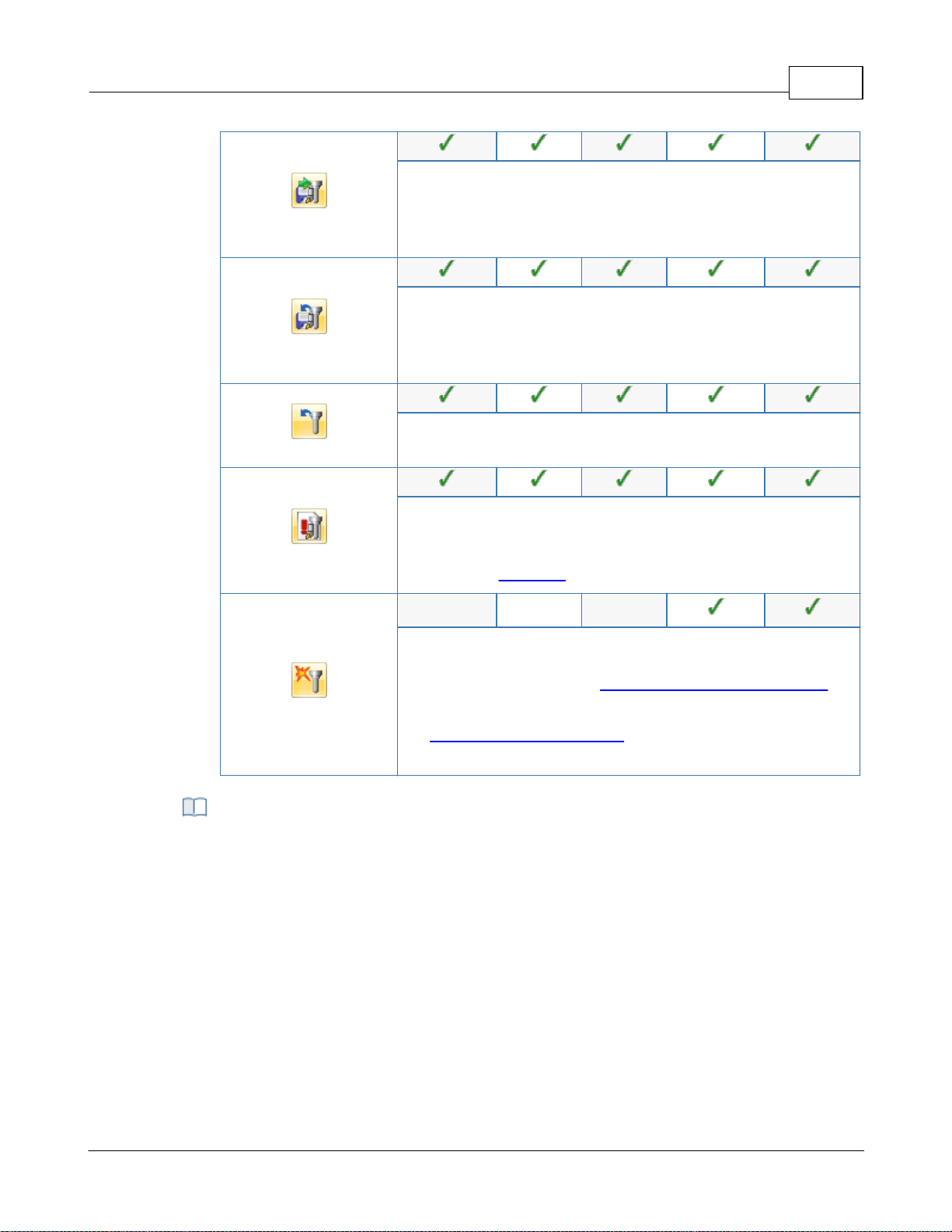
User Interface 50
Select Tools from Library: The select tool library button enables
you to select tools from a previously saved tool library. Refer to
the following section for additional information - Select Tools
from Library
Save Tool Library: This button enables the created tools to be
saved in a tool library file. The file can be saved in the desired
directory and read in when required. Refer to the following
section for additional information - Save Tool Library
Unload Tool Library: This button will unload the current Tool
Library.
List Tools: The button brings up all the tool properties
associated with the tools currently recorded in the current MILL
session. Refer to the following section for additional
information - List Tools
Compute Tool Holder Collisions*: Determines tool holder
collision with the part geometry. Refer to the following section
for additional information - Compute Tool Holder Collisions.
Note: This utility only supports single-segment tool holders.
See Create/Select Tool Holders for more information on
creating multi-segmented tool holders.
You can right-click on a Tool listed in the Mobs Browser to perform various functions.
These are listed below:
Right-click Options on Tools
© 2024 MecSoft Corporation
Page 52
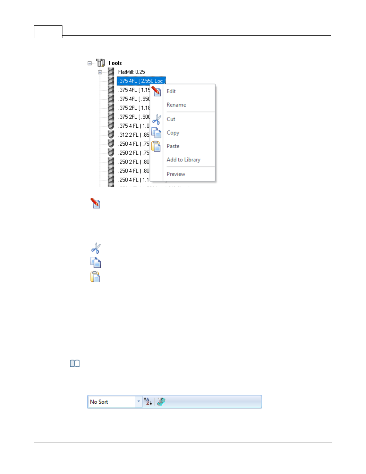
VisualCAD/CAM-MILL 2024 Reference51
Right-click Options on a Tool
Edit
Displays the Create/Edit Tool dialog allowing you to edit the Tool parameters.
Rename
Allows you to Rename the selected tool.
Cut / Copy / Paste
These options allow you to Cut or Copy the selected Tool to the Windows
Clipboard and then Paste it back to the Tools list to create a new tool using the
previous tool as a template.
Add to Library
This allows you to Add the selected Tool to an exiting Tool Library *.csv data file.
Preview
This will display a Preview of the selected Tool in the Graphics Window similar
to how the Tool displays during Simulation. The Tool will display at the origin of
the MCS for the current operation.
The following Tool Sorting rules (when set) will apply to both the Tools tab of the
Machining Objects Browser and the Create/Select Tools dialog.
Tools Toolbar Functions
© 2024 MecSoft Corporation
Page 53
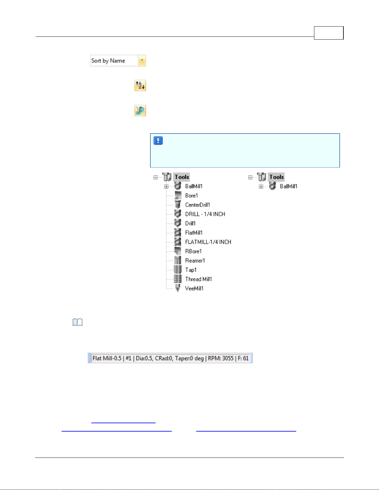
User Interface 52
Sorting Selector: This allows you to sort the tool list. You can
select No Sort or sort by Name, Number, Type and Diameter.
Sort in Ascending/Descending Order: This icon acts like a toggle to
switch between Ascending and Descending sort order.
List on the Tool used in Machining Operations: Toggle this icon to
list ONLY the tools currently assigned to an operation. Note: You
must Generate an operation for the assigned tool to be listed.
If you do not see any of your tools listed, check to make sure
this icon is toggled OFF. If no operations are using tools yet
and this icon is ON, then no tools will be listed!
Tools Sorted by Name
Tools Sorted by Used
The status bar displays the currently selected tool, tool tip radius & angle, spindle speed
and cut feedrate.
Status Bar, Tools Tab, Machining Objects Browser
Tools Status Bar
4.4.2 Regions Tab
Selecting the Regions tab under the Machining Objects (Mobs) Browser displays the Machining
Regions manager.
Note: See Right-Click Commands for a complete list of all right-click commands available from the
© 2024 MecSoft Corporation
Machining Operations (Mops) Browser and the Machining Objects (Mobs) Browser.
Page 54
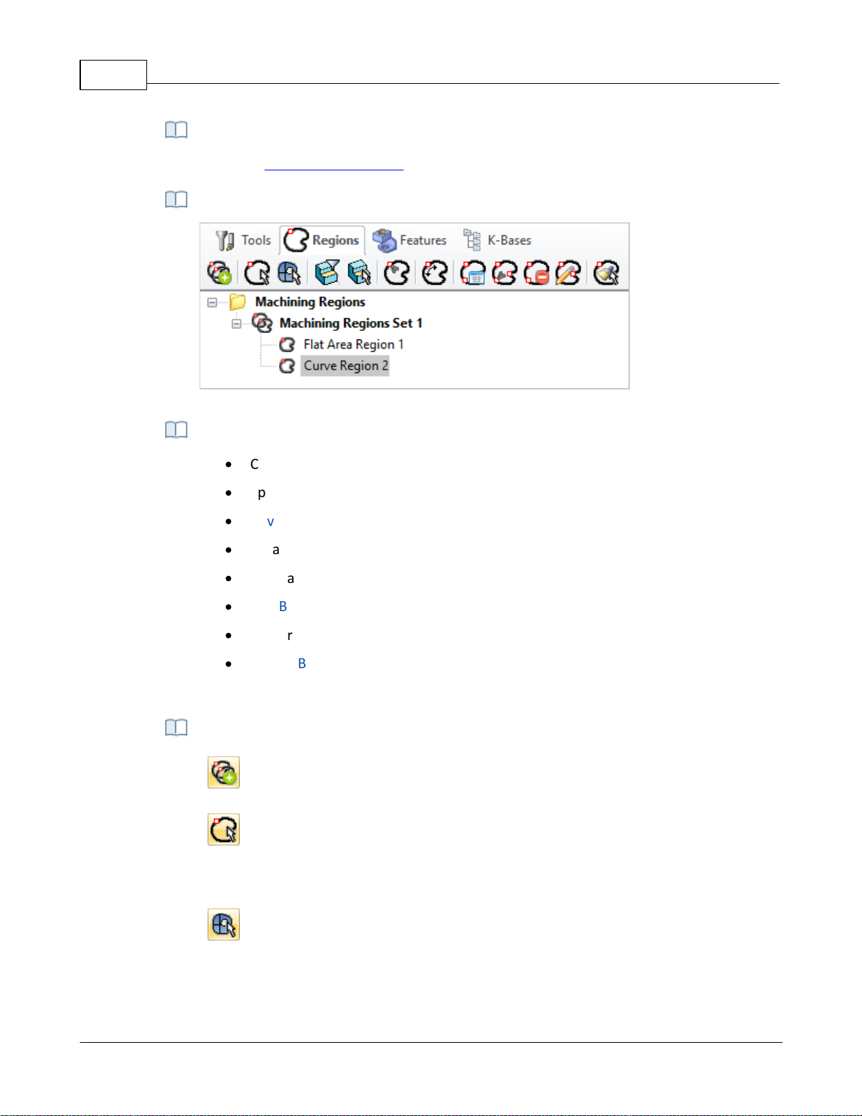
VisualCAD/CAM-MILL 2024 Reference53
There are right-click commands available for use in the Regions tab.
Regions Tab, Machining Objects (MObs) Browser
·
Create Pre-defined Machining Regions from curves and flat areas
·
Specify Start Point for closed curves
·
Reverse Curve Direction
·
Create Automatic Bridge Points
·
Manually Define Bridge Points
·
Edit Bridge Points
·
Edit predefined regions
·
Delete Bridge Points
These can then be selected as machining features for generating machining operations.
Create Machining Region Set
Creates a group that can contain one or more machining regions.
Select Curve
Allows you to select curves as pre-defined machining regions. Each contiguous
region is listed as a sub-region of the Machining Regions Set. You can edit each
sub-region independently.
Select Surface Edge Areas
Select surface edge curves to create a region.
Right-Click Commands
Regions Tab, Machining Objects (Mobs) Browser
The Regions tab allows you to:
Regions Tab Functions
© 2024 MecSoft Corporation
Page 55
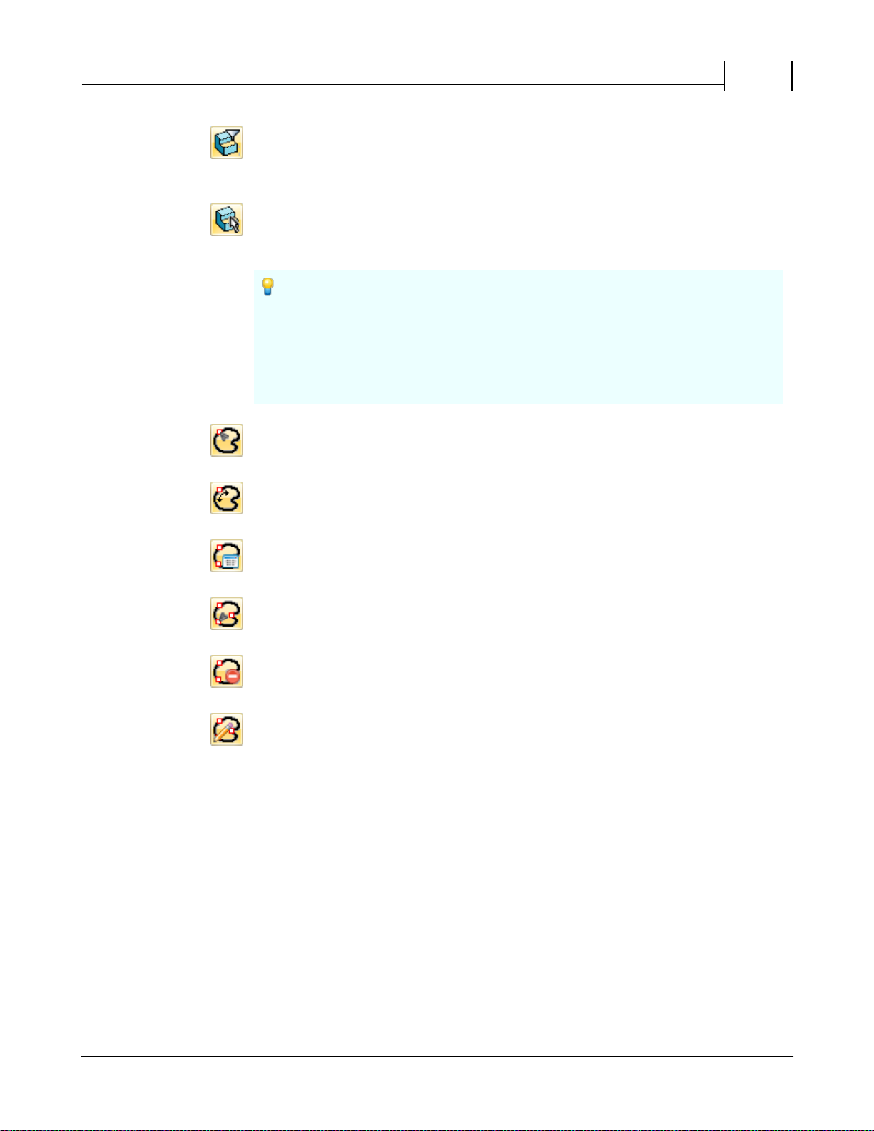
User Interface 54
Flat Areas Selection Filter
Displays a flat area region selection filter dialog which allows you to choose the
type of boundary areas to select for flat area selection.
Select Flat Areas
Creates a curve forming the boundary of select flat areas. The flat area could be
a face of solid or a plane.
If the Flat Area contains multiple closed curves (such as a flat rectangle
with a hole in the middle of it) and no Flat Area Selection Filters are set
then each closed curve is defined as a separate Curve Region and placed under
one Machining Region Set in the Mobs browser. Each Curve Region can then
be edited separately such as deleting, reversing direction or changing the start
point.
Select Start Point
Allows you to pick a start point for a selected curve region.
Reverse Cut Direction
Allows you to reverse curve direction for a selected curve region.
Automatic Bridge Points on Selections
Automatically creates bridge points for a selected curve region.
Manual Bridge Points on Selections
Allows manual selection of bridge points for a selected curve region.
Delete All Bridge Points in Selections
Deletes all bridge point for a selected curve region.
Edit Bridge Point in Selections
This allows the editing of a bridge point for the selected curve region.
Note: If you double-click on this icon, the command remains modal (i.e., active)
until you right-click in the drawing window to cancel it. This functionality allows
you to quickly edit all of your bridge points without having to re-execute the
command.
© 2024 MecSoft Corporation
Page 56
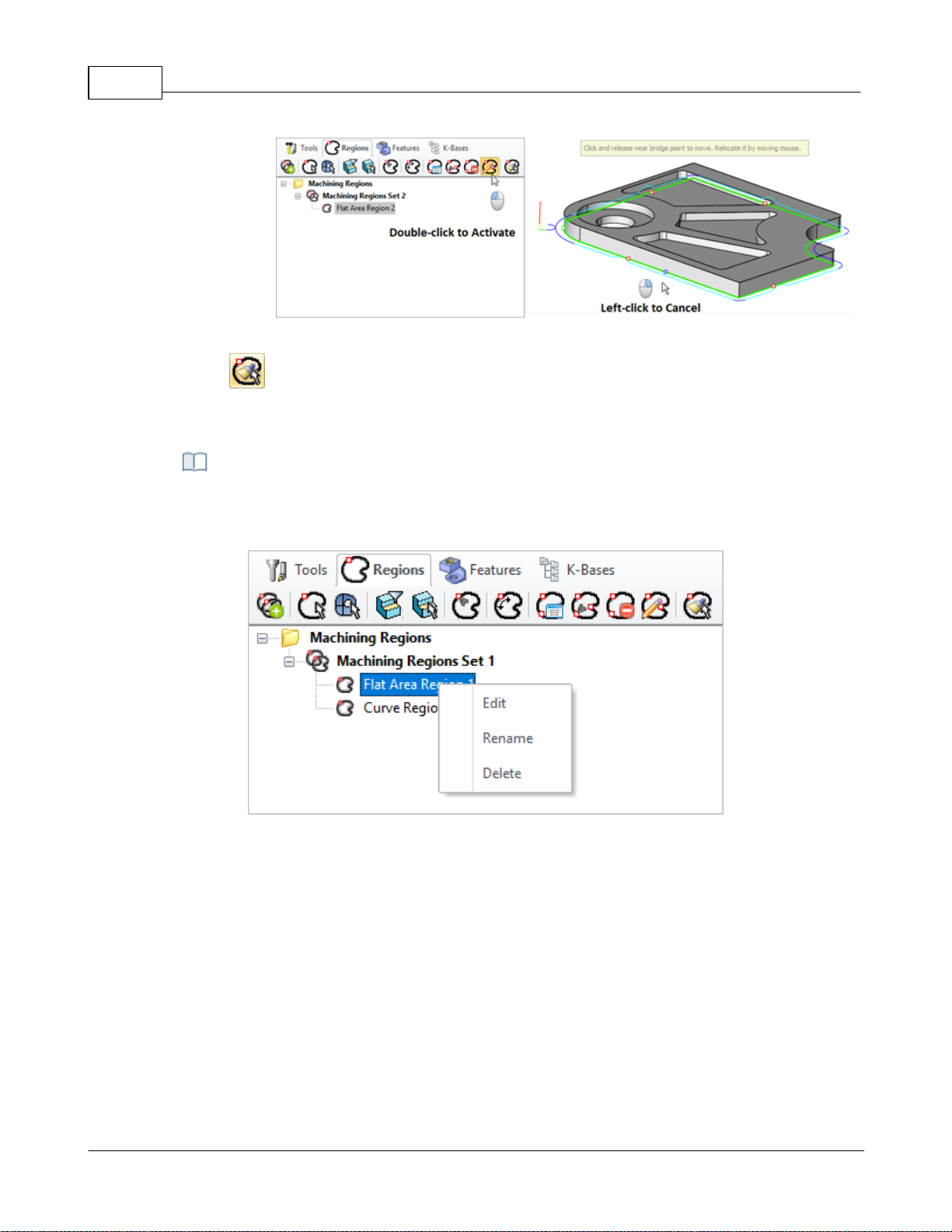
VisualCAD/CAM-MILL 2024 Reference55
Edit Bridge Points in Selected Region - Modal
Clone Region
Allows you to clone selected machining regions for geometrically identical
curves.
You can right-click on a Curve Region listed in the Mobs Browser to perform various
functions. These are listed below:
Right-click Options on a Tool
Edit
You can right click on a Region (Curve, Surface Edge, or Flat Area) to edit and
then add or remove geometries to the region.
Rename
This allows you to Rename the selected Region.
Delete
Use this Delete the selected Region from the set.
Right-click Options on Predefined Regions
© 2024 MecSoft Corporation
Page 57
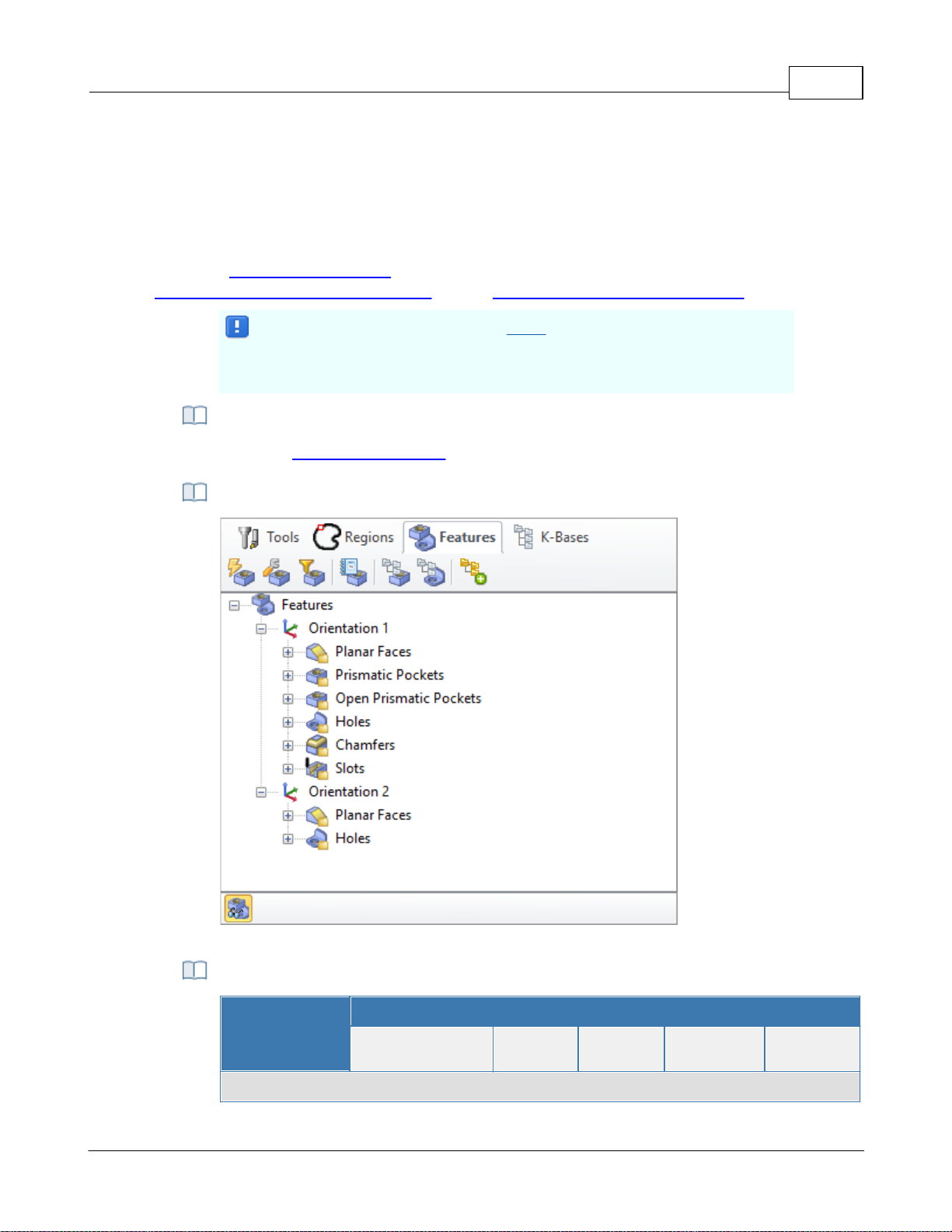
4.4.3 Features Tab
Important: Machining Features can ONLY be extracted from poly-surface
models (i.e., solid models). If your part model is not a solid, you must
"stitch" all surfaces into a poly-surface prior to Creating Machining Features!
There are right-click commands available for use in the Features tab.
The Machining Objects (MObs) Browser, Features Tab
Summary
Available Configuration
Xpress
(XPR)
Standard
(STD)
Expert
(EXP)
Professional
(PRO)
Premium
(PRE)
Features tab Command Icons
Selecting the Features tab under the Machining Objects Browser displays the Feature Manager. It
allows you to create and work with detected features from your 3D solid model. See
Understanding Feature Machining in VisualCAM for important information about Machining
Features.
Note: See Right-Click Commands for a complete list of all right-click commands available from the
Machining Operations (Mops) Browser and the Machining Objects (Mobs) Browser.
Right-Click Commands
The Features tab (Machining Objects Browser)
User Interface 56
Features Tab Commands
© 2024 MecSoft Corporation
Page 58
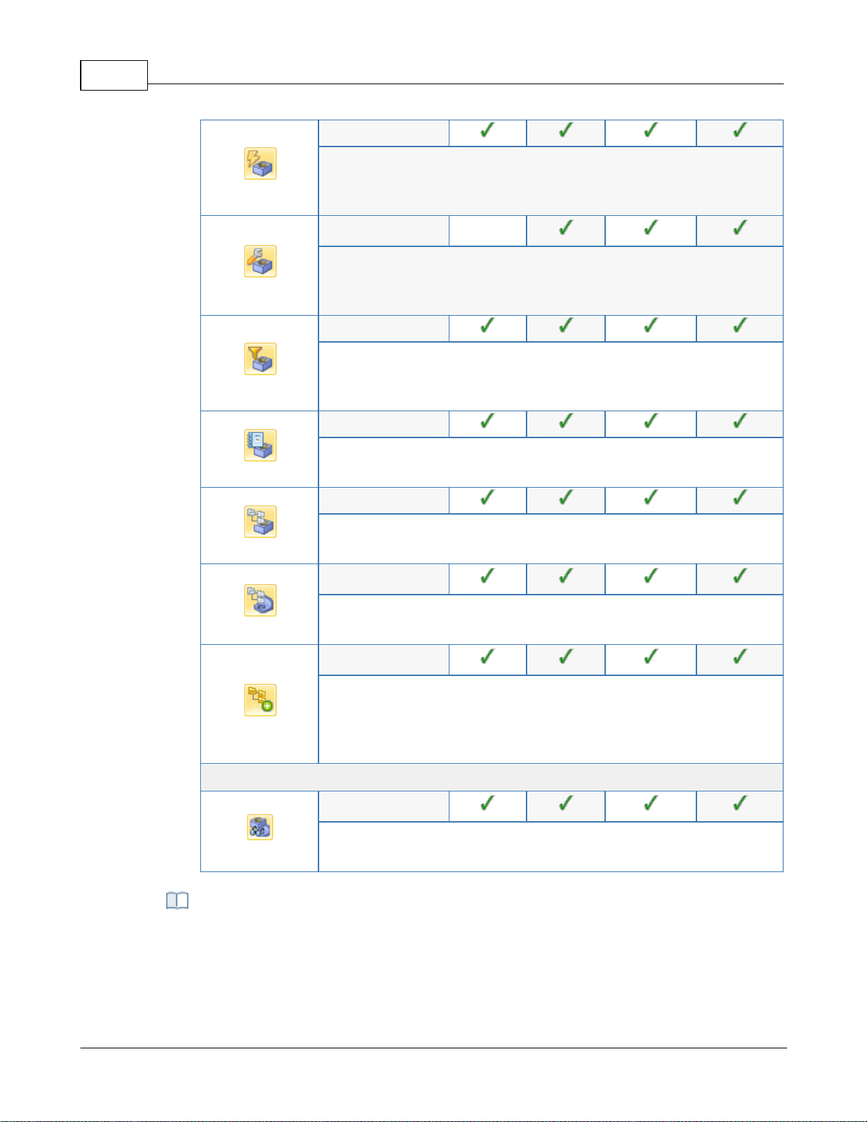
VisualCAD/CAM-MILL 2024 Reference57
-
Performs Automatic Feature Detection (AFD) from your part model
based all possible machining Orientations. See Automatic Feature
Detection (AFD) for more information.
-
-
Performs Interactive Feature Detection (IFD) by selecting a face from
your part model to define the machining Orientation. See Interactive
Feature Detection (IFD) for more information.
-
Allows you to Set Filters for Feature Detection so that only certain
feature types or hole diameters are detected. See Set Filters for
Feature Detection for more information.
-
Allows you to list all of your detected features. See List Features for
more information.
-
Allows you to setup a features knowledge base. See: Setup Features
Knowledge Base.
-
Allows you to create a hole feature machining operation. See: Create
Hole Feature Machining Operation.
-
Allows you to perform Automatic Feature Machining (AFM) based on
the default (AFM) Knowledge Base defined in the Features section of
the CAM Preferences dialog. See Automatic Feature Machining (AFM)
for more information.
Features tab Toolbar Icons
-
This icon Toggles the display of Features in the drawing window. It is
located at the bottom of the browser when the Features tab is active.
After you have performed either AFD or IFD on your part model, you can move the cursor
over a part feature and its identification name will display. This is the name created for
the feature and listed in the Features tree.
Feature Identification on Cursor Highlight
© 2024 MecSoft Corporation
Page 59
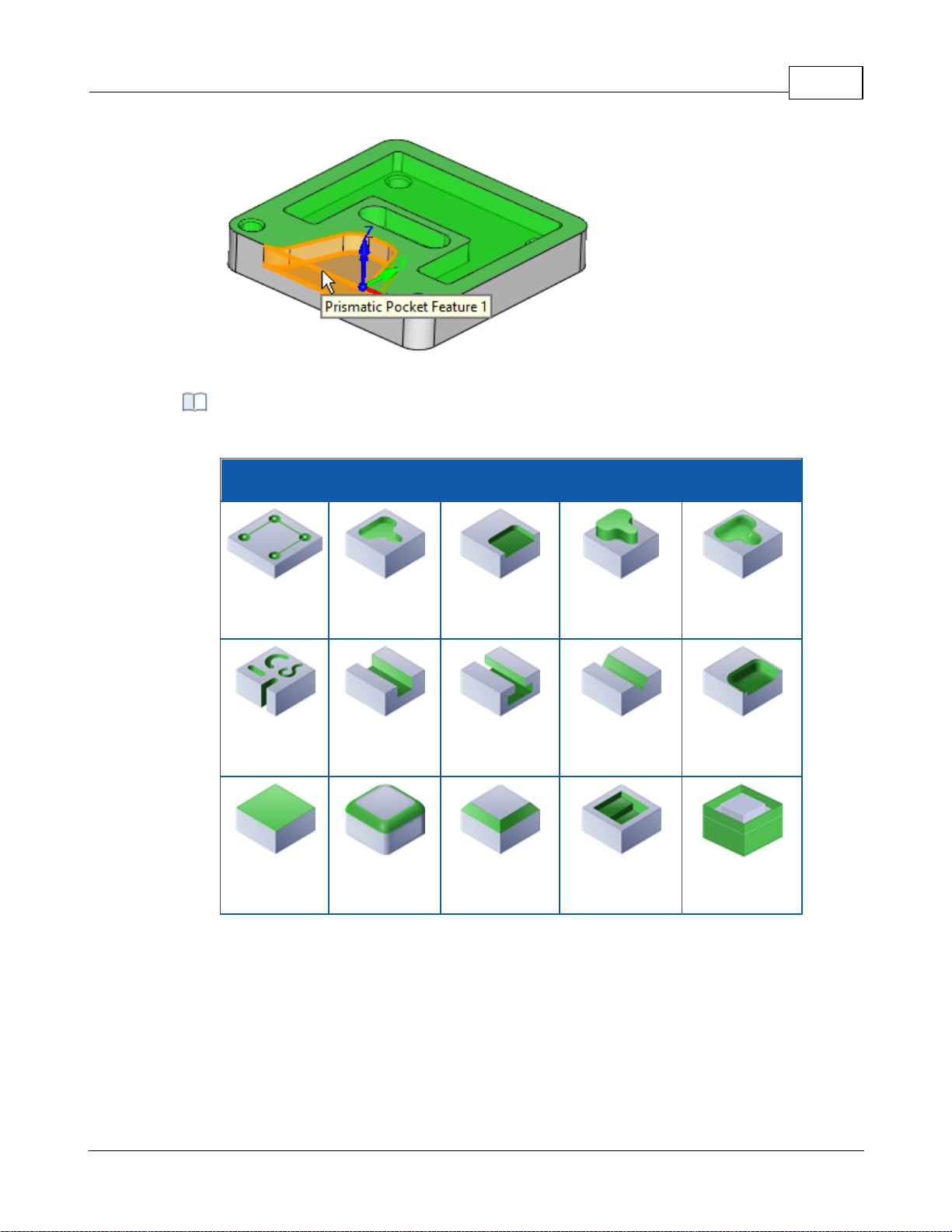
Feature Identification on Cursor Highlight
Feature Types Recognized
The feature types recognized are listed in the table below:
Feature Types Detected
Hole
Prismatic
Pocket
Open
Prismatic
Pocket
Boss
General
Pocket
(3 Axis)
Slot
Open Slot
T-Slot
V-Slot
Open General
Pocket
(3 Axis)
Planar Face
Fillet
Chamfer
Stepped
Prismatic
Pocket
Silhouette
User Interface 58
© 2024 MecSoft Corporation
Page 60
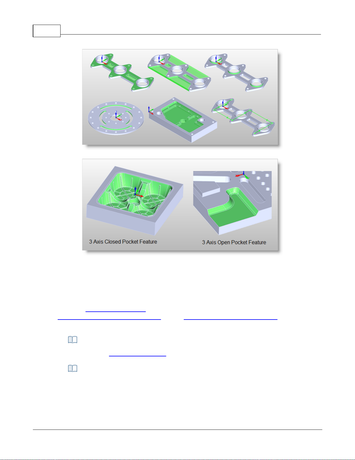
VisualCAD/CAM-MILL 2024 Reference59
Some 2 Axis Feature Examples
Some 3 Axis Feature Examples
There are right-click commands available for use in the K-Bases tab.
4.4.4 K-Bases Tab
Selecting the K-Bases tab under the Machining Objects Browser displays the Knowledge Base
manager.
Note: See Right-Click Commands for a complete list of all right-click commands available from the
Machining Operations (Mops) Browser and the Machining Objects (Mobs) Browser.
Right-Click Commands
The Machining Objects (Mobs) Browser, K-Bases Tab
© 2024 MecSoft Corporation
Page 61
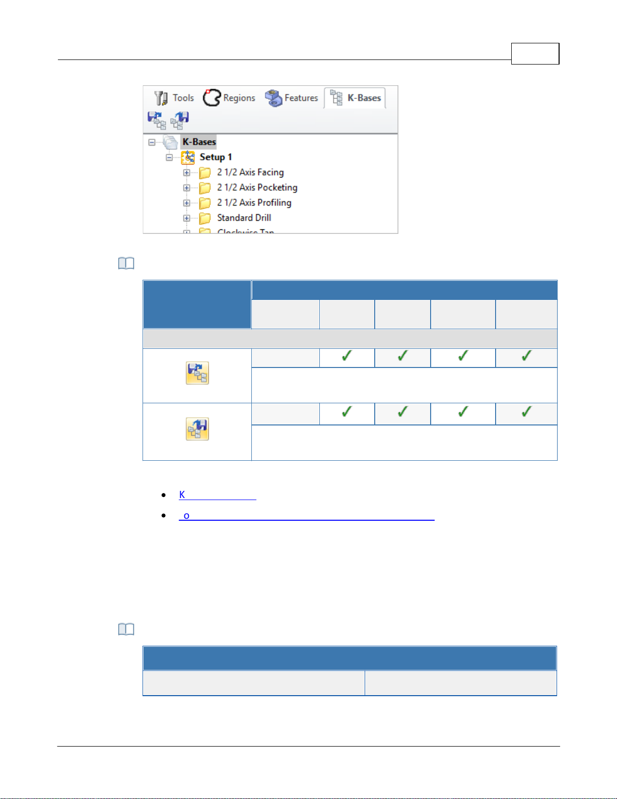
The Machining Objects (MObs) Browser, K-Bases Tab
K-Bases Tab Functions
Summary
Available Configuration
Xpress
(XPR)
Standard
(STD)
Expert
(EXP)
Professional
(PRO)
Premium
(PRE)
Features tab Command Icons
-
Load Knowledge Base: Allows you to select a machining
operations knowledge base to load.
-
Save Knowledge Base: Allows saving of knowledge bases which
can be archived and used across other files.
Refer to the following sections for a detailed description on Knowledge base
·
Knowledge Base
·
Load Knowledge Base from Machining Objects Browser
VisualCAM Right-Click Commands - MILL Module
Action Item
Right-Click Commands
User Interface 60
4.5 Right-Click Commands
You can perform a variety of commands by right-clicking on items within the Machining Browser
and Machining Job. The tables below lists each of the available commands.
from the Machining Operations (MOps) Browser
© 2024 MecSoft Corporation
Page 62
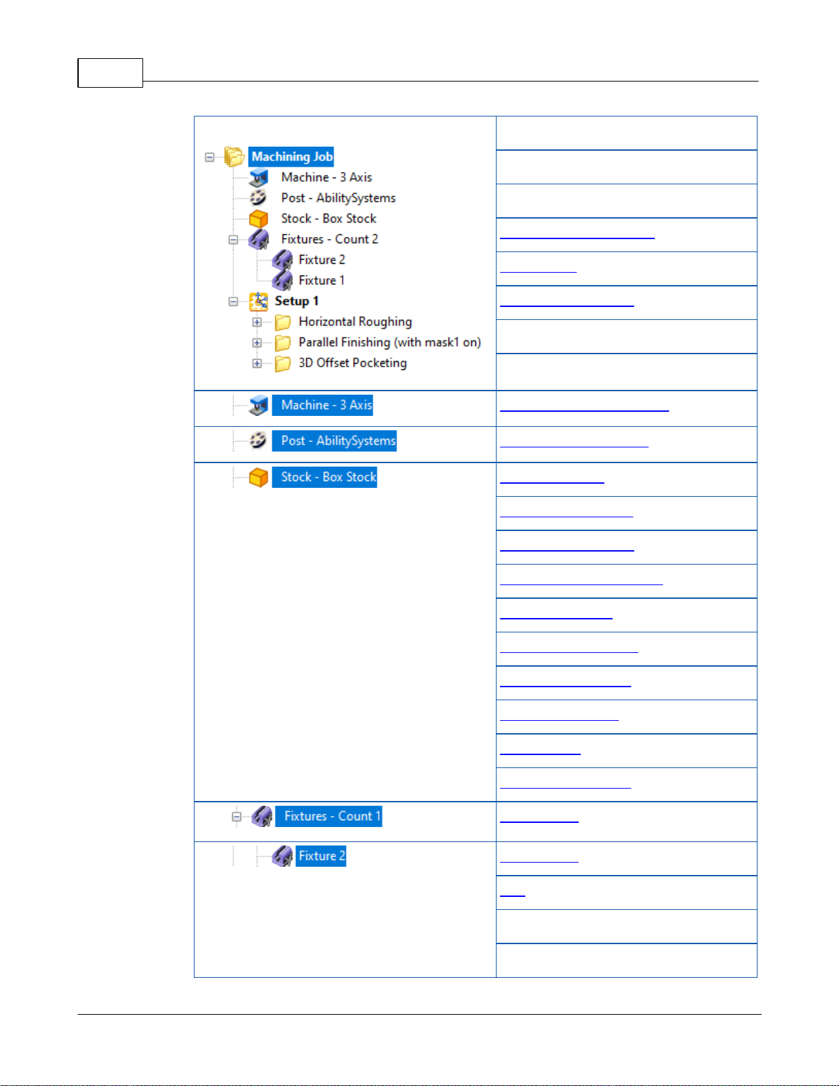
VisualCAD/CAM-MILL 2024 Reference61
Machining Browser
Regenerate All
Post All
Simulate All
Save to Knowledge Base
Information
Shop Documentation
Delete All
Delete All Dirty MOps
Machine Tool Setup Dialog
Set Post Options Dialog
Box Stock Dialog
Part Box Stock Dialog
Cylinder Stock Dialog
Part Cylinder Stock Dialog
Part Offset Dialog
Extruded Stock Dialog
Stock from Selection
Export Stock to STL
Delete Stock
Remove Simulations
New Fixture
New Fixture
Edit
Rename
Delete
© 2024 MecSoft Corporation
Page 63
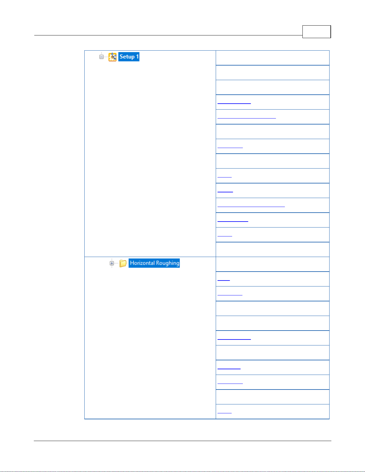
User Interface 62
Regenerate
Post
Simulate
Information
Shop Documentation
Rename
Suppress
Cut
Copy
Paste
Save to Knowledge Base
New Setup
Align
Delete All Dirty MOps
Regenerate
Post
Simulate
Simulate Until
Simulate to End
Information
Edit
Rename
Suppress
Cut
Copy
© 2024 MecSoft Corporation
Page 64
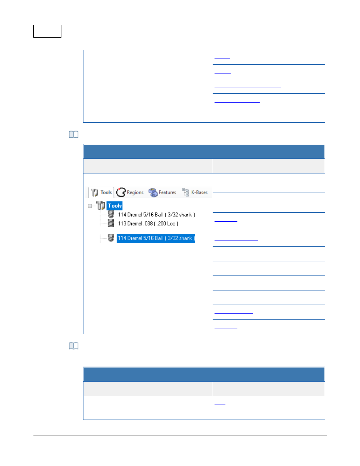
VisualCAD/CAM-MILL 2024 Reference63
Paste
Clone
Save to Knowledge Base
Save As Defaults
Machining Operation Properties dialog
VisualCAM Right-Click Commands - MILL Module
Action Item
Right-Click Commands
Machining Objects Browser / Tools Tab
Cut
Paste
Tool List
Create Edit Tool
Rename
Cut
Copy
Paste
Add to Library
Preview
VisualCAM Right-Click Commands - MILL Module
Action Item
Right-Click Commands
Machining Objects Browser / Regions Tab
Edit
from the Tools tab of the Machining Objects (MObs) Browser
from the Regions tab of the Machining Objects (MObs)
© 2024 MecSoft Corporation
Page 65
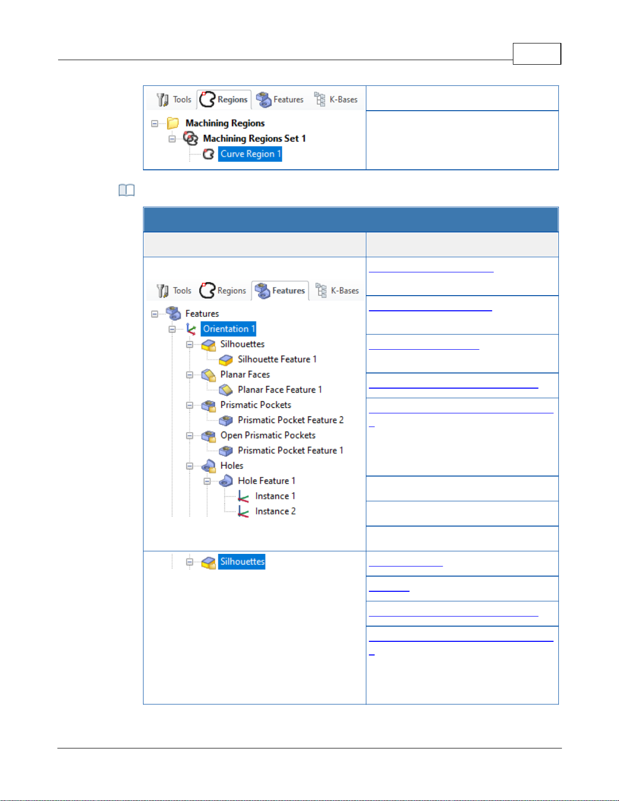
Rename
Delete
from the Features tab of the Machining Objects (MObs)
VisualCAM Right-Click Commands - MILL Module
Action Item
Right-Click Commands
Machining Objects Browser / Features Tab
3 Axis Horizontal Roughing (feature
dependent)
3 Axis Horizontal Finishing (feature
dependent)
3 Axis Parallel Finishing (feature
dependent)
Automatic Feature Machining (AFM)
Automatic Feature Machining using KBs
>
DefaultAFM_INCH
DefaultAFM_MM
Rename
Delete
Suppress
Note: Feature group may vary.
2 Axis Roughing (Feature Dependent)
Profiling (Feature Dependent)
Automatic Feature Machining (AFM)
Automatic Feature Machining using KBs
>
DefaultAFM_INCH
DefaultAFM_MM
User Interface 64
© 2024 MecSoft Corporation
Page 66
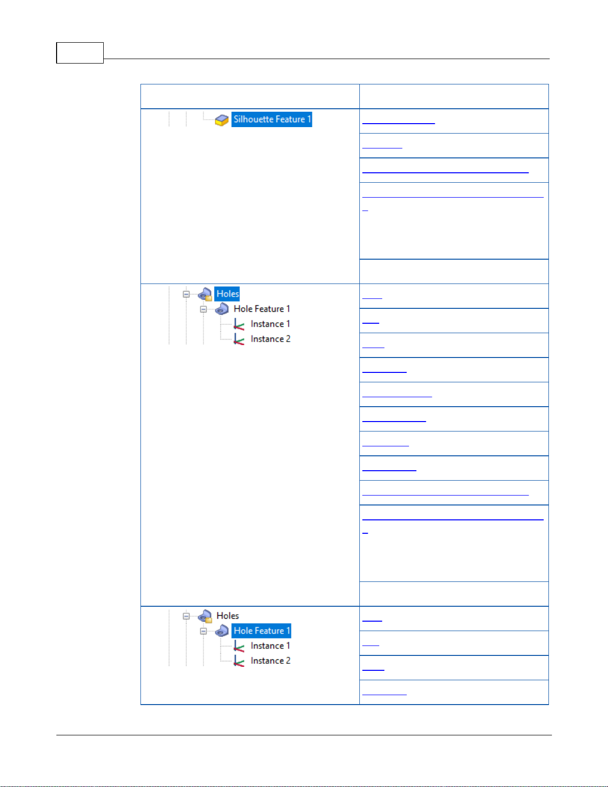
VisualCAD/CAM-MILL 2024 Reference65
Delete
Note: Feature type may vary.
2 Axis Roughing (Feature Dependent)
Profiling (Feature Dependent)
Automatic Feature Machining (AFM)
Automatic Feature Machining using KBs
>
DefaultAFM_INCH
DefaultAFM_MM
Delete
Drill
Tap
Bore
Rev. Bore
Hole Pocketing
Hole Profiling
Threading
Chamfering
Automatic Feature Machining (AFM)
Automatic Feature Machining using KBs
>
DefaultAFM_INCH
DefaultAFM_MM
Delete
Drill
Tap
Bore
Rev. Bore
© 2024 MecSoft Corporation
Page 67
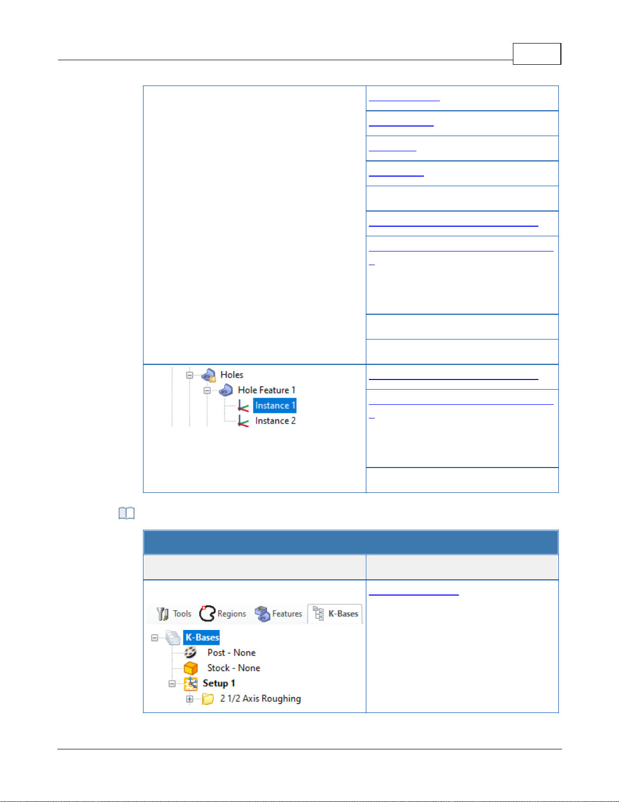
User Interface 66
Hole Pocketing
Hole Profiling
Threading
Chamfering
Create Hole Feature Machining KB
Automatic Feature Machining (AFM)
Automatic Feature Machining using KBs
>
DefaultAFM_INCH
DefaultAFM_MM
Rename
Delete
Automatic Feature Machining (AFM)
Automatic Feature Machining using KBs
>
DefaultAFM_INCH
DefaultAFM_MM
Delete
VisualCAM Right-Click Commands - MILL Module
Action Item
Right-Click Commands
Machining Objects Browser / K-Bases Tab
Set Selection Rules
from the K-Bases tab of the Machining Objects (MObs)
© 2024 MecSoft Corporation
Page 68

VisualCAD/CAM-MILL 2024 Reference67
From the VisualCAD Home Ribbon Bar, select the VisualCAM menu from the Plugins pane
and then select MILL. This displays the machining operations browser and by default is
docked to the left half of the application window next to the view bar.
Select the Tools Machining Objects button located on the Machining Operations Browser
just to the left of the Program tab. This displays the Machining Objects Browser below
the operations browser.
4.6 Docking Browsers
Both Machining Operations Browser and the Machining Objects Browser windows are dock-able
windows. This means these windows can be docked in any position in VisualCAD. This section
describes the procedure to be used to dock both of these windows such that they are stacked
vertically.
Step 1: Launch the MILL Browser
Step 2: Display the Tools, Machining Objects Browser
© 2024 MecSoft Corporation
Page 69
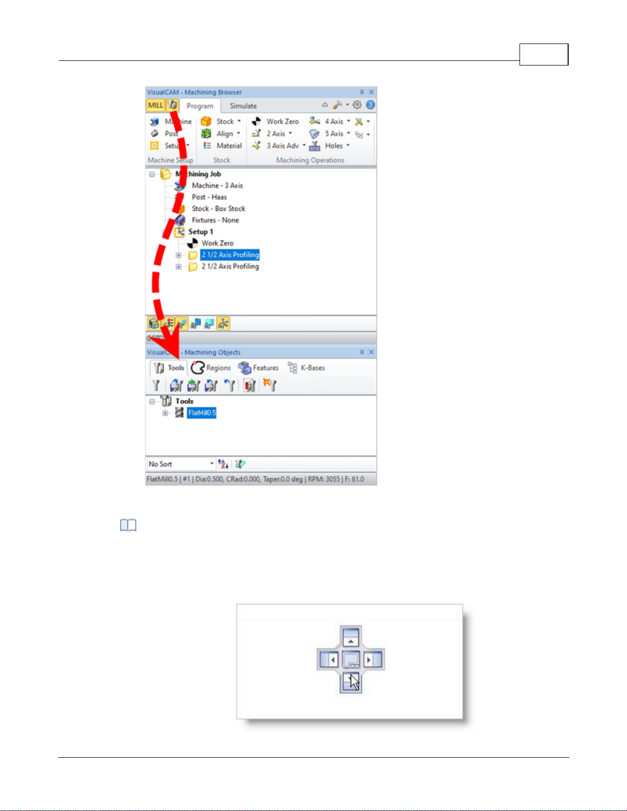
User Interface 68
Step 2: Display the Tools, Machining Objects Browser - Premium
Configuration shown
Selecting the title bar and holding the left mouse button down and dragging the browser
window displays a widget that allows you to dock the browser to desired location. You
can dock a browser inside of another browser or have them docked side by side by using
the controls on the widget.
Step 3: Drag & Drop the Browser
© 2024 MecSoft Corporation
Page 70
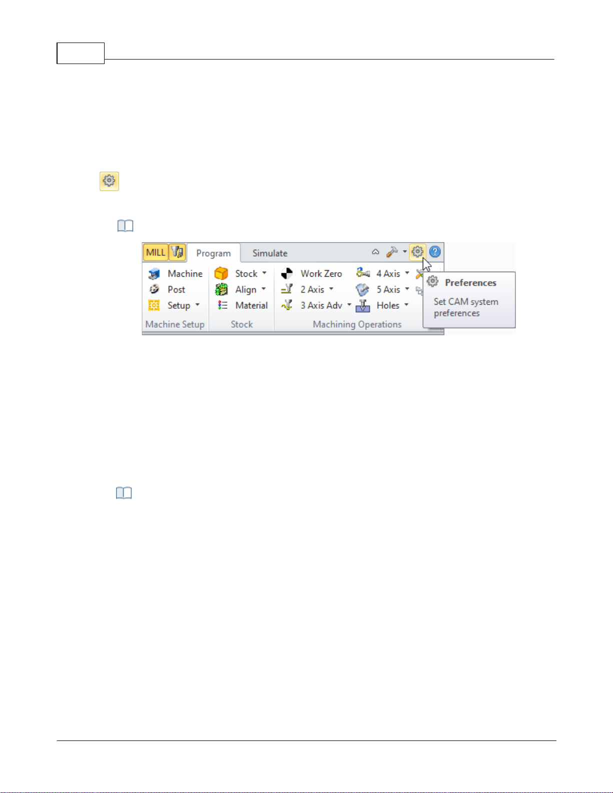
VisualCAD/CAM-MILL 2024 Reference69
For example: Selecting the button on the widget with arrow pointing downwards on and
releasing the left mouse button docks the selected browser below the specified
browser.
Set CAM System Preferences menu item
4.7 CAM Preferences
You can set various CAM Preferences that will be saved even after you exit the program.
Select the Preferences icon from the Machining Browser. When you install a new
VisualCAM update you are choose to import your CAM Preferences from one version to the next.
The CAM Preferences Icon
4.7.1 Geometry
You can set the colors to display various objects using this dialog. To change each of the color
settings in this dialog select the colored button next to the item of interest. This will bring up the
color selection dialog, which can be used to choose the color needed. Once a color has been
selected the button will change its color to the selected one.
Dialog Box: CAM Preferences > Geometry
© 2024 MecSoft Corporation
Page 71
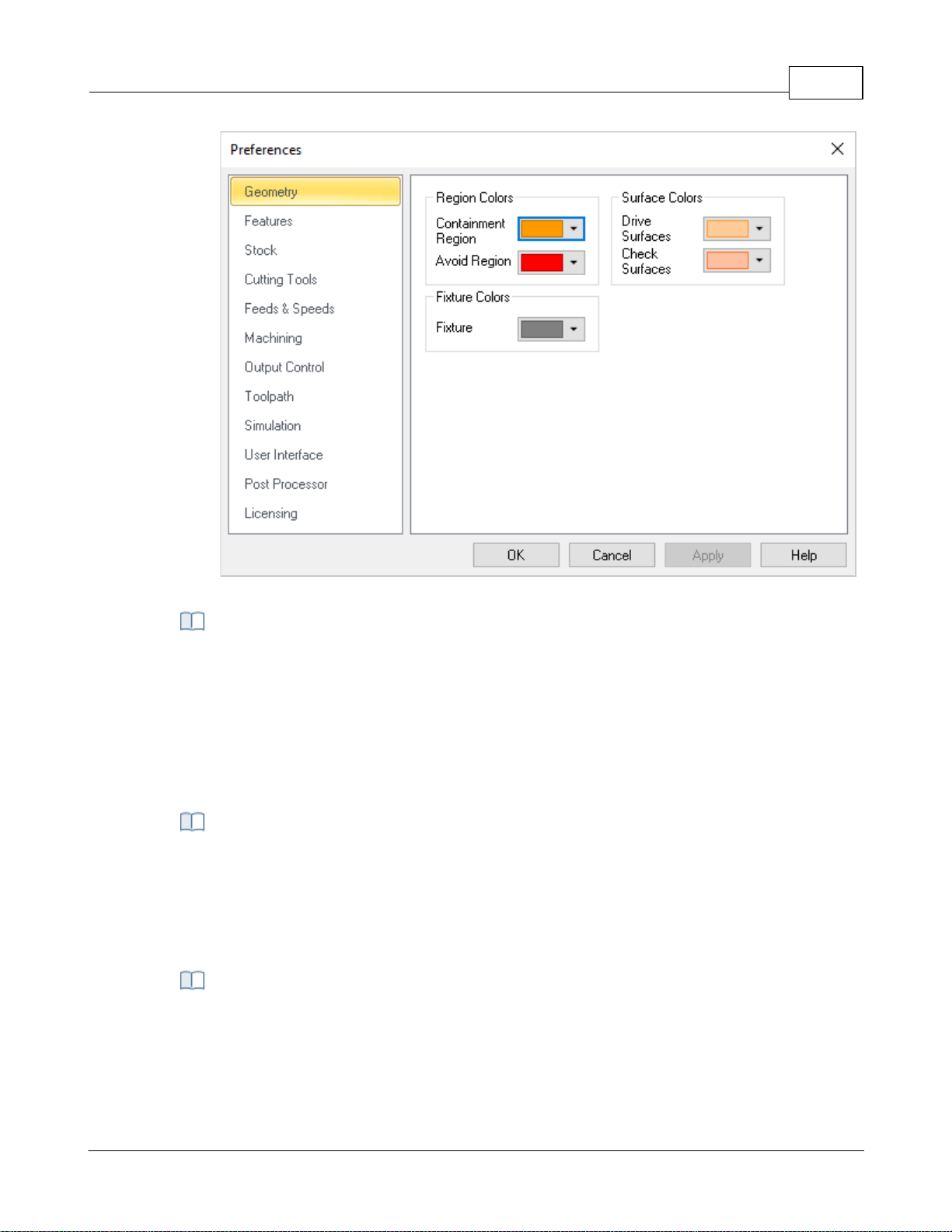
User Interface 70
CAM Preferences > Geometry
Containment Region
Use this color selector to set the display color for Containment Regions (i.e., your Control
Geometry).
Avoid Region
Use this color selector to set the display color for Avoid Regions (i.e., your Control
Geometry).
Drive Surfaces
Use this color selector to set the display color for Drive Surfaces (5 Axis).
Check Surfaces
Use this color selector to set the display color for Check Surfaces (5 Axis).
Fixture
Use this color to represent fixture geometry.
Region Colors
Surface Colors
Fixture Colors
© 2024 MecSoft Corporation
Page 72
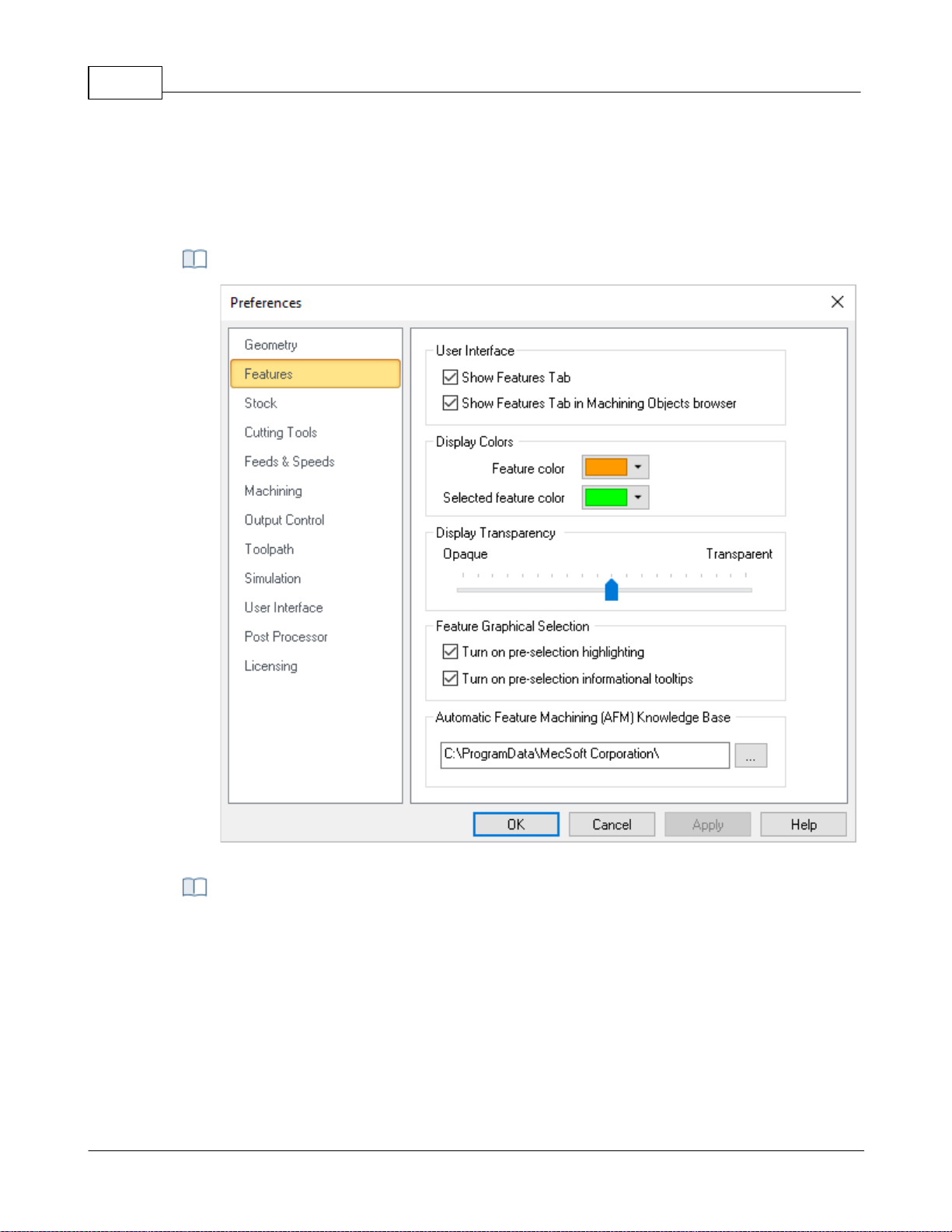
VisualCAD/CAM-MILL 2024 Reference71
CAM Preferences > Features
Show Features Tab
Check this box to display the Features tab. If this is not checked, then you will not be
able to perform Feature Recognition.
Show Features Tab in Machining Objects Browser
Check this box if you prefer to have the Features tab appear in the Machining Objects
Browser (to the right of the Regions tab). If this box is not checked, the Features tab will
appear in the Machining Browser (to the left of the Program tab) as shown below.
4.7.2 Features
Here you can set preferences related to Features (for MILL module only). Note: These
preferences are not available in XPR (Xpress) configuration.
Dialog Box: CAM Preferences > Cutting Tools
User Interface
© 2024 MecSoft Corporation
Page 73
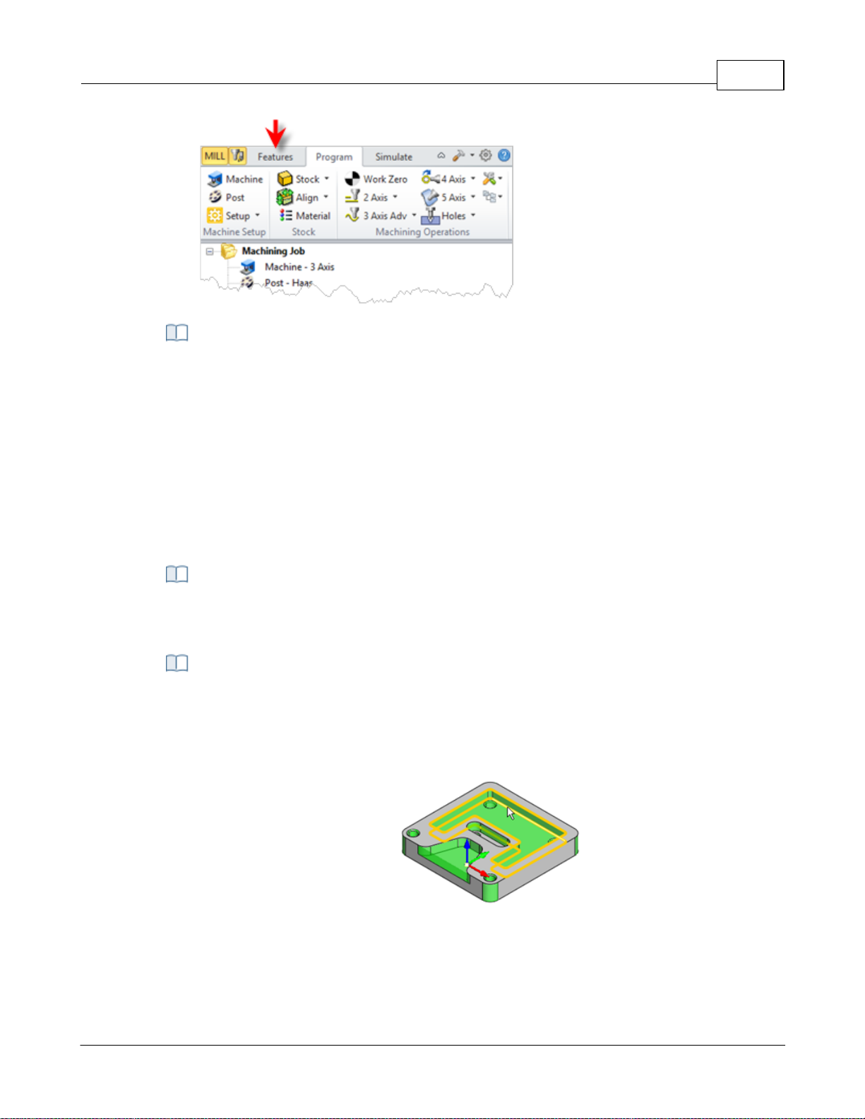
Display Colors
This section allows you to set the default Feature Color and default Selected Feature
Color.
Feature Color
Here you can set the default Feature Color. When an operation is selected from the
Machining Job tree of the Machining Browser, that is derived from a Machining Feature,
the feature is highlighted using this color.
Selected Feature Color
Here you can set the default Selected Feature Color. When a Machining Feature is
selected from the Features tab of the Machining Objects Browser, the feature is
highlighted using this color.
This refers to how transparent feature colors (see Colors above) on the screen when
features are displayed.
This section allows you to set selection preferences for detected Features.
Turn on pre-selection highlight
Check this box to highlight detected Features when the cursor moves over them in the
graphics window.
Feature pre-selection highlight
Turn on pre-selection tips
Check this box to display Feature section tips when the cursor moves over a detected
Feature in the graphics window.
User Interface 72
Display Transparency
Feature Graphical Selections
© 2024 MecSoft Corporation
Page 74
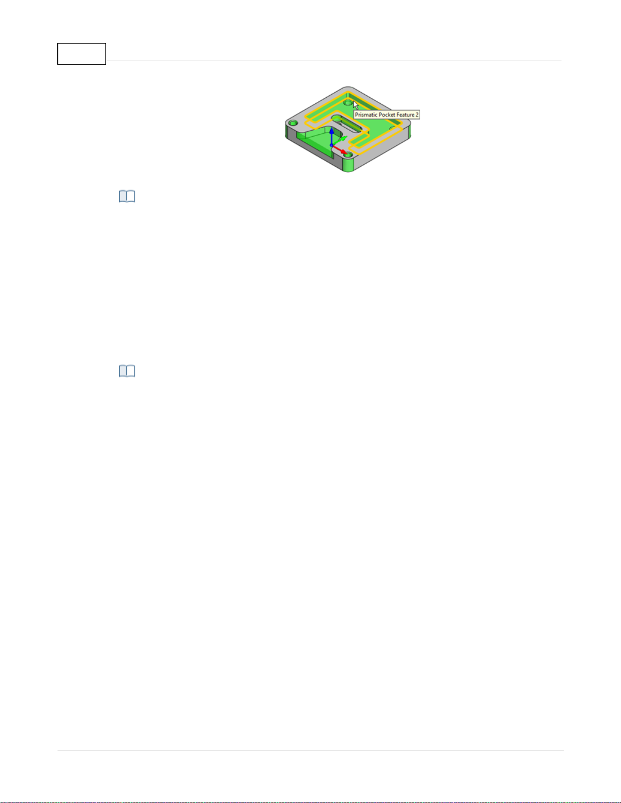
VisualCAD/CAM-MILL 2024 Reference73
Feature pre-selection tips
This field displays the path the default Automatic Feature Machining (AFM) Knowledge
Base. Select the ... button to select a different path.
C:\ProgramData\MecSoft Corporation\VisualCAM
2024\FeatureBasedMachiningKBs\DefaultAFM_INCH. vkb
Users can set the simulation preferences using this dialog:
4.7.3 Stock
You can set the simulation preferences using this dialog. Note: Some options are not available in
XPR (Xpress) configuration.
Automatic Feature Machining (AFM) Knowledge Base
Dialog Box: CAM Preferences > Stock
© 2024 MecSoft Corporation
Page 75
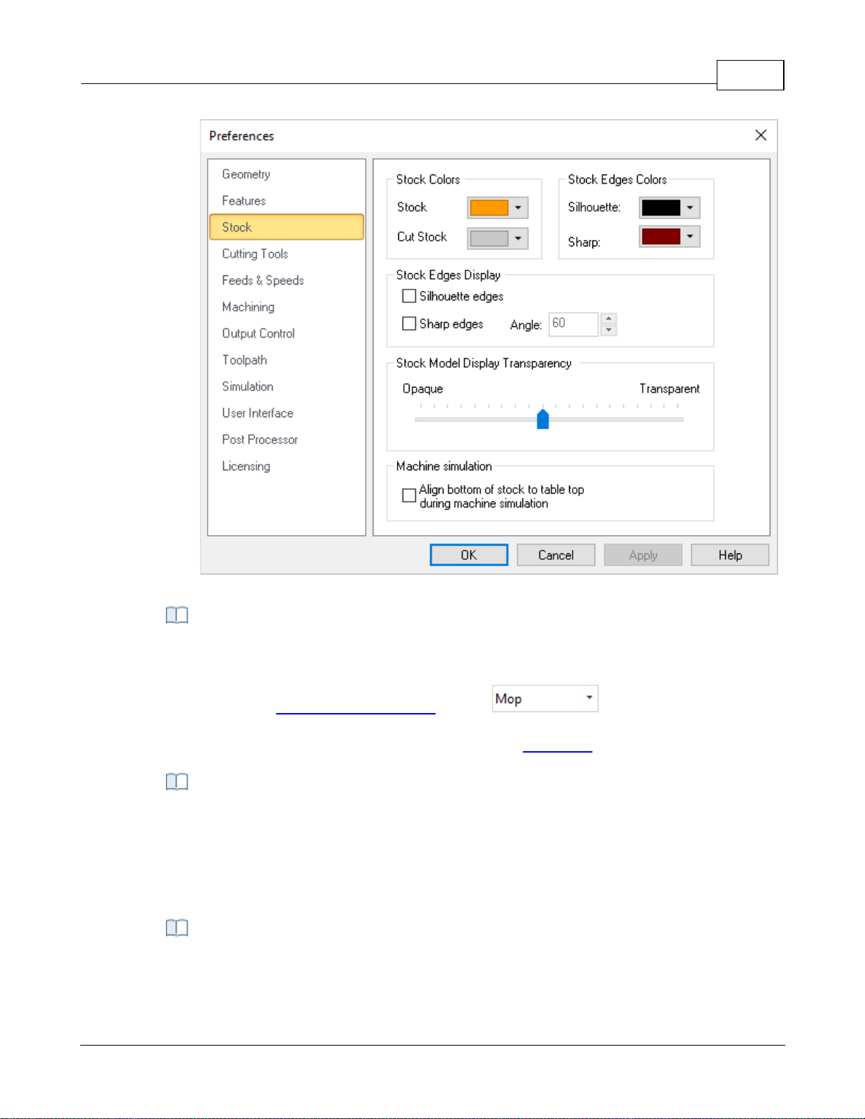
User Interface 74
CAM Preferences > Stock
Here you can set the stock colors. You can differentiate between uncut Stock, Cut Stock,
Silhouette Edges and Sharp Edges by specifying different colors for them here.
Note: If the Simulation Display State is set to then the Color assigned
using the Machining Operation Properties is used to display the cut stock. Right-click on
an operation in the Machining Job tree and select Properties to set this color.
This section allows you to control the Stock Edges Display states. For example, you can
check the boxes to display Silhouette Edges and Sharp Edges as well as the Angle to
display for stock edges. Silhouette Edges and Sharp Edge colors are set using the Colors
section of this dialog. Experimentation is advised until you are comfortable with the way
your stock display.
Use this slider to adjust the Stock Model Transparency when the Program tab is selected
(i.e., when you are not simulating).
Stock & Stock Edge Colors
Stock Edges Display
Stock Model Display Transparency
© 2024 MecSoft Corporation
Page 76
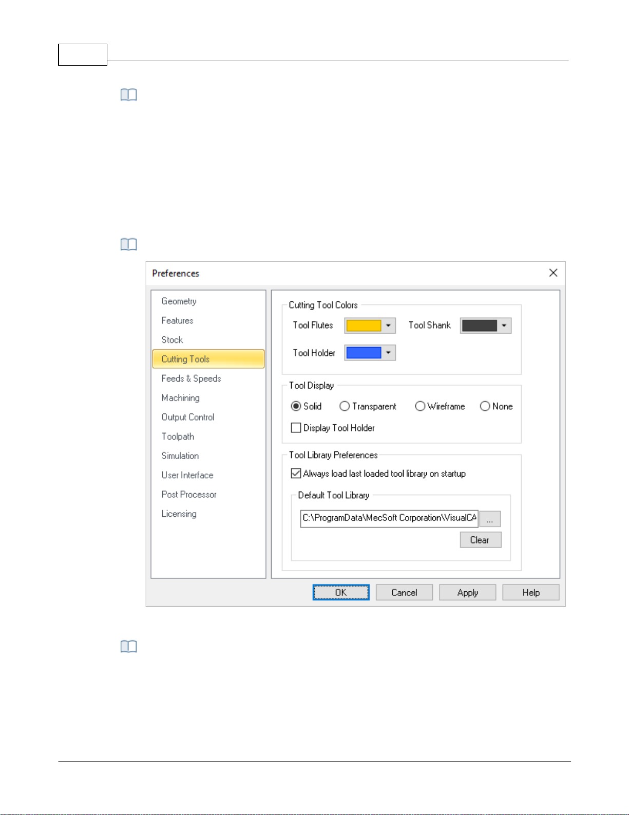
VisualCAD/CAM-MILL 2024 Reference75
During Machine Tool Simulations, you can check this box to automatically position the
bottom of the in-process stock stock on the top of the machine bed.
CAM Preferences > Cutting Tools
Note: Menu selections on the left may change depending on module and configuration
Use the color selectors to set the default display colors for the cutting tool. The Tool
Flutes, Tool Shank and Tool Holder can each be assigned a different.
Machine Simulation
4.7.4 Cutting Tools
You can set the Tool Library to load on startup and also specify the location of your Tool Library
files.
CAM Preferences > Cutting Tools
Cutting Tool Colors
© 2024 MecSoft Corporation
Page 77
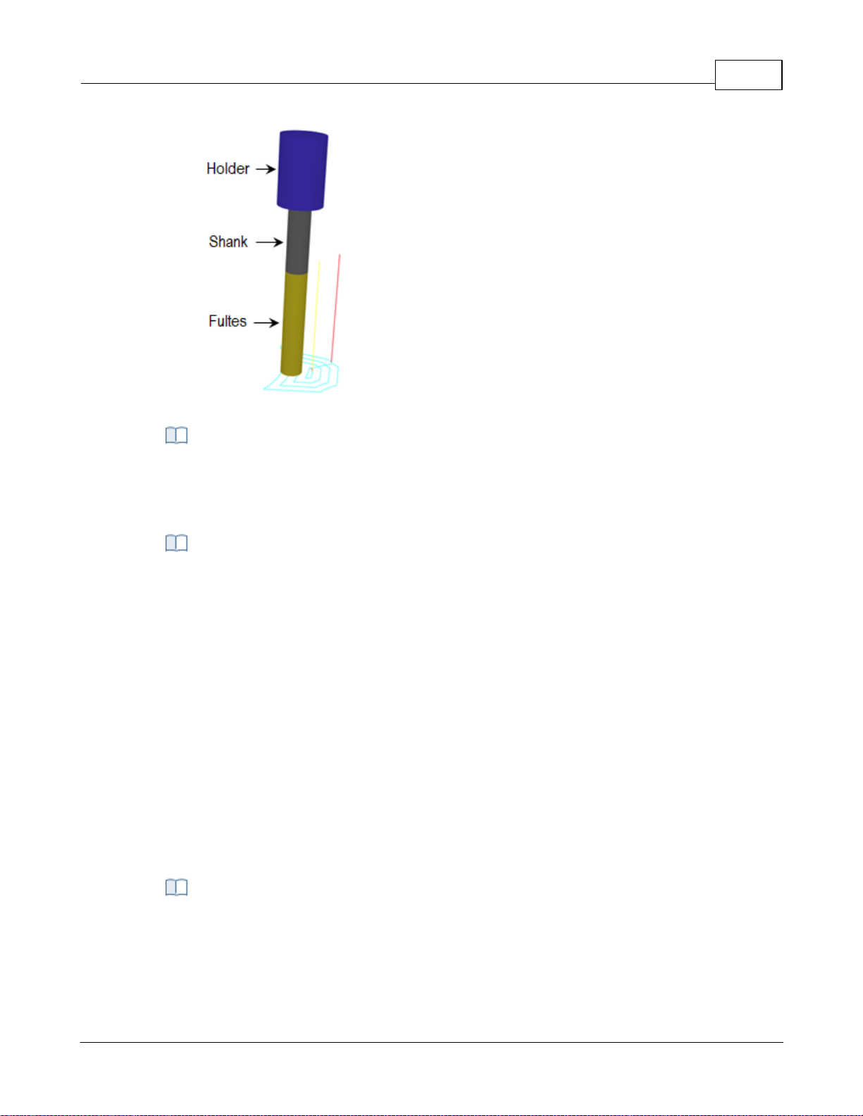
Tool Display
The cutting tool can be displayed as either Solid, Transparent, Wireframe or None by
selecting the desired option. You can also toggle the display of the Tool Holder by
checking or un checking the box provided.
This defines your Tool Library preferences:
Always load last loaded tool library on startup
If you check this box, every time VisualCAM loads, the last loaded Tool Library will be
loaded automatically.
Default tool library path
Optionally you can specify the file path for your default tool library files. Note: It is
recommended that you save your custom tool library files to a location outside of the
VisualCAM install path. This will keep them from being overwritten when you install
new updates of VisualCAM.
User Interface 76
Tool Library Preferences
4.7.5 Feeds & Speeds
You can set the Feeds & Speeds preferences using this dialog.
CAM Preferences > Feeds & Speeds
© 2024 MecSoft Corporation
Page 78
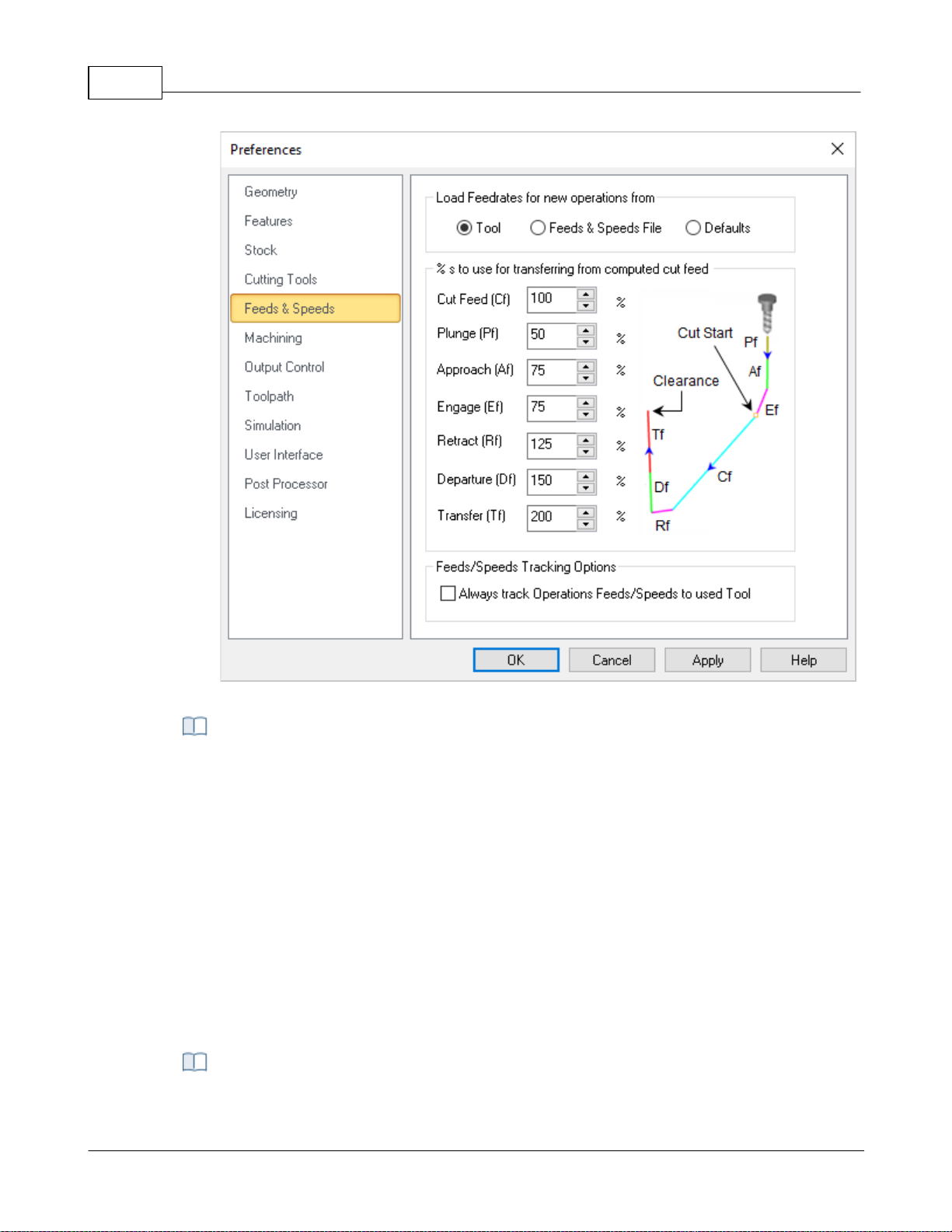
VisualCAD/CAM-MILL 2024 Reference77
CAM Preferences > Feeds & Speeds
This allows you to select a preference option for loading Feeds/Speeds from table or
from tool or use defaults when creating a new operation.
Tool
Selecting this option loads the feeds/speeds saved with the tool when creating a new
operation.
Table
Selecting this option loads the feeds/speeds based on the material selected when
creating a new operation.
Defaults
Selecting this option loads the feeds/speeds from the default knowledge base when
creating a new operation. If default knowledge base is set to undefined, the system
defaults would be used for loading feeds and speeds.
Load Feedrates for operations from
% s to use for transfer from computed cut feed
© 2024 MecSoft Corporation
Page 79

These % values apply when using the Load from File option (i.e., commonly referred to
as the Feeds & Speeds Calculator) from either the Create/Edit Tools dialog of from the
Feeds & Speeds tab of any of the toolpath operation dialogs. 100% of the Cut Feed
specified in this dialog is applied and a percentage of the Cut Feed is used to populate
the remaining feedrates for Plunge, Approach, Engage, Retract, Departure and Transfer.
You can set the % values to use here.
Feeds/Speeds Tracking Options
When you select the Load from Tool option from any of the toolpath operation dialogs,
the Feeds & Speeds specified for the active tool are populated into the Feeds & Speeds
tab of the operation's dialog. You can check this box to perform this automatically when
new toolpath operations are created.
4.7.6 Machining
You can set the machining preferences using this dialog.
User Interface 78
CAM Preferences > Machining
© 2024 MecSoft Corporation
Page 80
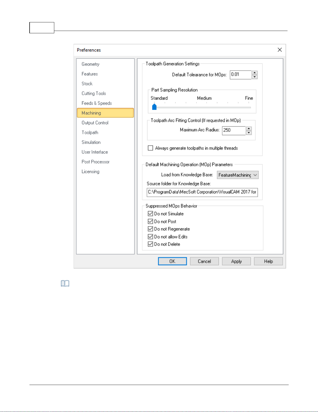
VisualCAD/CAM-MILL 2024 Reference79
CAM Preferences: Machining
Default Tolerance for Mops
Enter the default tolerance to use for new machining operations. You can edit this
parameter manually from the Cut Parameters tab of each machining operation (Mop)
dialog.
Part Sampling Resolution
This slider is used to control the display quality of the simulated model. Standard is
faster but with lower display quality. For large parts, use the Standard or Medium
options, while for smaller parts Medium or Fine options would work satisfactorily.
Toolpath Arc Fitting Control (If requested in Mop)
Toolpath Generation Settings
© 2024 MecSoft Corporation
Page 81

Some toolpath operations support Arc Fitting. If supported, the option is located on the
Advanced Cut Parameters tab of the operation's dialog.
Maximum Arc Radius
Some toolpath operations support Arc Fitting. You can enter here the Maximum Arc
Radius that can be created.
Always generate toolpath in multiple threads
Check this box to Always generate toolpath in multiple threads. The system will
distribute the computing of multiple toolpaths to different cores in your processor
simultaneously rather than sequentially. Refer to Multi-threading Manager section for
additional information.
Default Machining Operation (Mop) Parameters
Load from Knowledge Base
This allows you to select a Default Knowledge Base to load for creating machining
operations. Selecting a knowledge base as Default loads the operation parameters when
creating new operations. If no Default knowledge base is specified, the system defaults
are used for machining operation parameters.
Source Folder for Knowledge Base
This is the source folder where the Default Knowledge Base are stored.
When you Suppress Machining Operations (Mops) you can apply one or more of these
conditions. Check each box to enable that condition and then pick OK to close this
dialog.
User Interface 80
Suppressed Mops Behavior
4.7.6.1 Multi-threading Manager
This distributes computing of toolpath to different cores in your processor simultaneously rather
than process them sequentially when regenerating multiple operations.
© 2024 MecSoft Corporation
Page 82
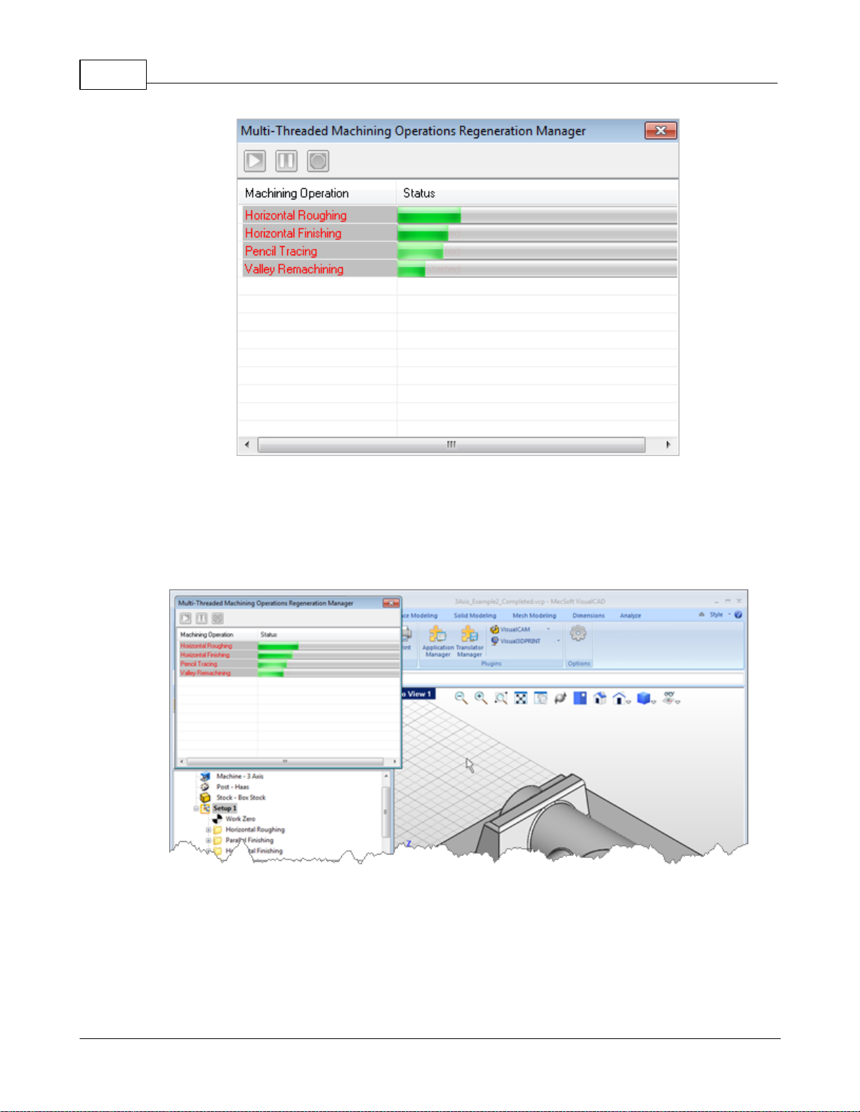
VisualCAD/CAM-MILL 2024 Reference81
Multi-threading Manager
Multi-threading Manager window displayed
To enable generation of toolpath using multi-threading manager, select Always generate toolpath
in multiple threads from Machining Preferences located under CAM Preferences in the Machining
browser.
Regenerating the Machining Job, Setup or machining operations displays the multi-threading
manager window and indicates the progress of the toolpath computation.
You can still continue working with the application when the toolpath generation is in progress
with the multi-threading manager dialog active.
© 2024 MecSoft Corporation
Page 83
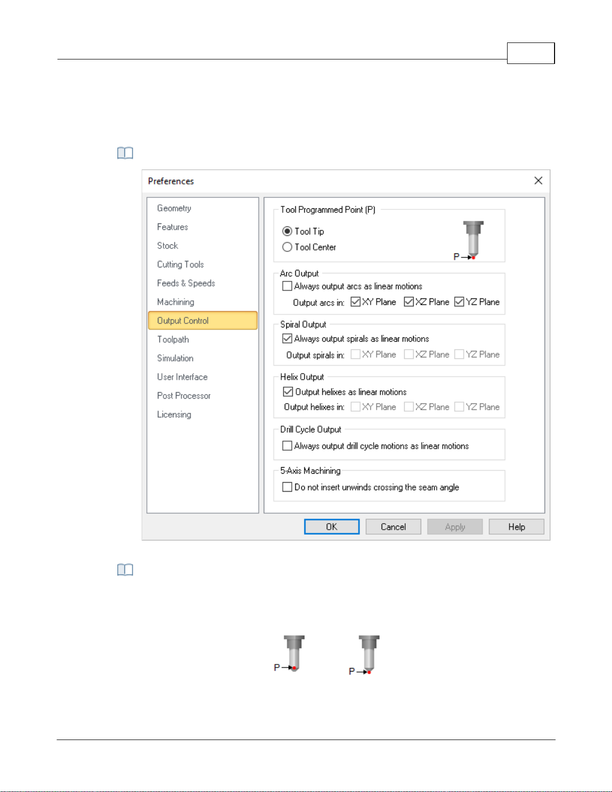
4.7.7 Output Control
CAM Preferences: Machining
The toolpath can be output as the tool tip or the tool center. If Tool Center is selected,
the toolpath will be offset by the difference in the height of the tool tip and tool center.
The default value is the Tool Tip.
Center
Tip
You can set the output control preferences using this dialog.
CAM Preferences > Output Control
User Interface 82
Tool Programmed Point (P)
© 2024 MecSoft Corporation
Page 84

VisualCAD/CAM-MILL 2024 Reference83
Changing machining preferences requires regeneration of machining operations to
apply the changes.
Some NC machine controllers do not have arc output. For such type of controllers, the
arcs that are generated in the toolpath can be output as linear segments by selecting
these check boxes.
Always Output Arcs as Linear Motions
If your controller does not support arc g-code motions, check this box to output arcs as
linear segments.
XY Plane
Check this box to Perform Arc Fitting . The system will attempt to fit arcs along the
computer toolpath if they lie within the three principal planes (XY Plane, XZ Plane or YZ
Plane).
Off
On
XZ Plane
Arcs can be fitted to linear toolpaths that lie on one of the three principal planes XY, XZ
or YZ. Check the box for which plane to fit arcs to.
Arc Fitting
YZ Plane
Arcs can be fitted to linear toolpaths that lie on one of the three principal planes XY, XZ
or YZ. Check the box for which plane to fit arcs to.
Arc Fitting
Arc Output
Spiral Output
© 2024 MecSoft Corporation
Page 85

Some NC machine controllers do not have spiral output. For such type of controllers, the
spirals that are generated in the toolpath can be output as linear segments by selecting
these check boxes.
Output Spiral Motions as Linear Segments
If your controller does not support spiral g-code motions, check this box to output spiral
motions as linear segments.
XY Plane / XZ Plane / YZ Plane
The system will attempt to fit spirals along the computed toolpath if they lie within the
three principal planes (XY Plane, XZ Plane or YZ Plane). Check the box to enable spirals in
each respective plane.
Helix Output
Some NC machine controllers do not have helical output. For such type of controllers,
the helixes that are generated in the toolpath can be output as linear segments by
selecting these check boxes.
Output Helixes as Linear Segments
If your controller does not support helical g-code motions, check this box to output helix
motions as linear segments.
XY Plane / XZ Plane / YZ Plane
The system will attempt to fit helixes along the computed toolpath if they lie within the
three principal planes (XY Plane, XZ Plane or YZ Plane). Check the box to enable helixes
in each respective plane.
When this box is un checked, the spindle head will rewind when it meets a surface seam.
When checked, no un-winds are performed at seams.
This section refers to Hole Machining Drill Cycles.
Always output drill cycle as linear motions.
Check the box if your wish to always output Drill Cycles as linear motions.
User Interface 84
Do not insert unwinds crossing the seam angle
Drill Cycle Output
4.7.8 Toolpath
These preferences relate to the graphical display of toolpath cut motions.
© 2024 MecSoft Corporation
CAM Preferences > Toolpath
Page 86
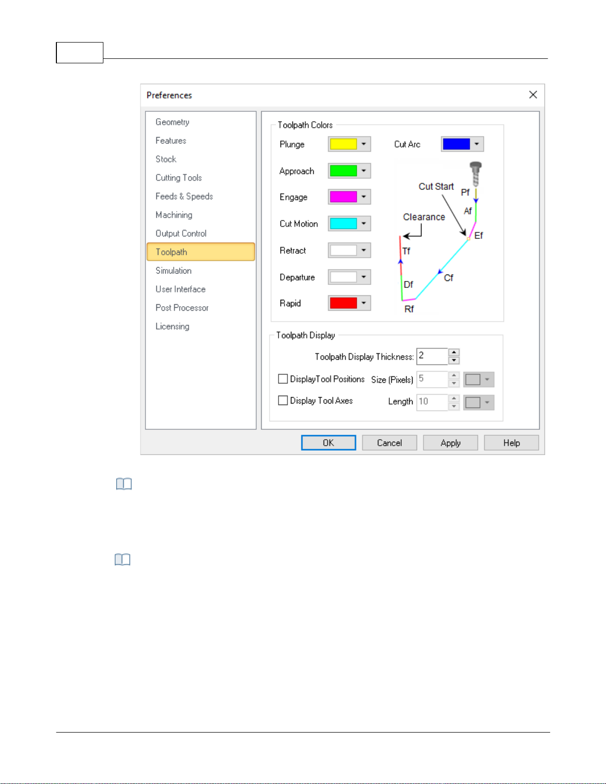
VisualCAD/CAM-MILL 2024 Reference85
CAM Preferences > Toolpath
Use the color selectors to define the display color for each motion in the toolpath. The
following can be set: Cut Motion, Plunge, Approach, Engage, Retract, Departure, Rapid
and Cut Arc.
These preferences control the display of the toolpath in the graphics window.
Toolpath Display
This refers to the graphical display of toolpaths. Enter a value to effect the size of the
toolpath during display.
Display Tool Positions Size (Pixels)
Check this box to display tool position locators. Each coordinate represents one tool
position. Then enter the pixel size for the locator point as well as the color of the
position points. You can also use the color selector to assign a color to these markers.
Toolpath Colors
Toolpath Display
© 2024 MecSoft Corporation
Page 87

Display Tool Axis
Check this box to display the Tool Axis line. You can then enter a Length for the axis line
and use the Color selector to assign it a color.
4.7.9 Simulation
You can set the simulation preferences using this dialog. Note: Some options are not available in
XPR (Xpress) configuration.
Dialog Box: CAM Preferences > Simulation
User Interface 86
© 2024 MecSoft Corporation
Page 88
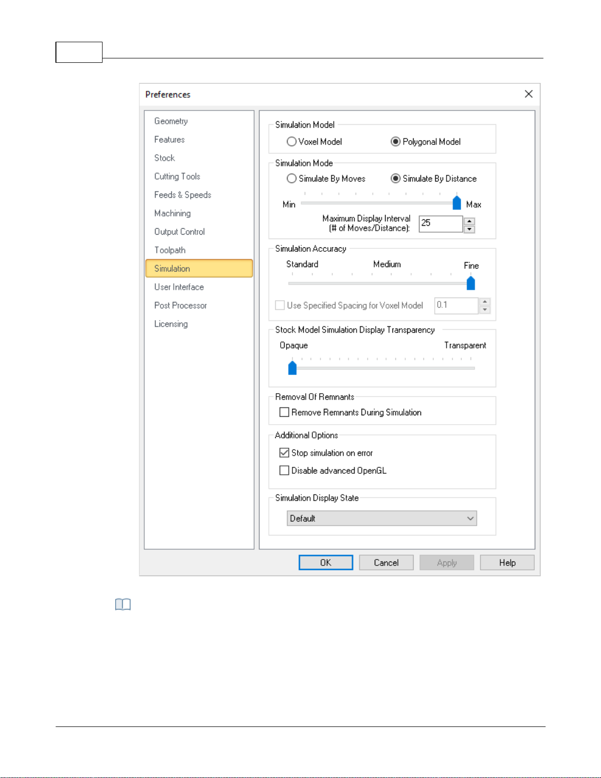
VisualCAD/CAM-MILL 2024 Reference87
CAM Preferences > Simulation
In the VisualCAM MILL module you can choose between two simulation models. One is
called the Voxel Model and the other the Polygonal Model.
Voxel Model
The Voxel Model is a fast simulation model that is primarily used for 3 axis applications.
It is especially useful when there are large amounts of toolpath blocks to be simulated.
Simulation Model
© 2024 MecSoft Corporation
Page 89
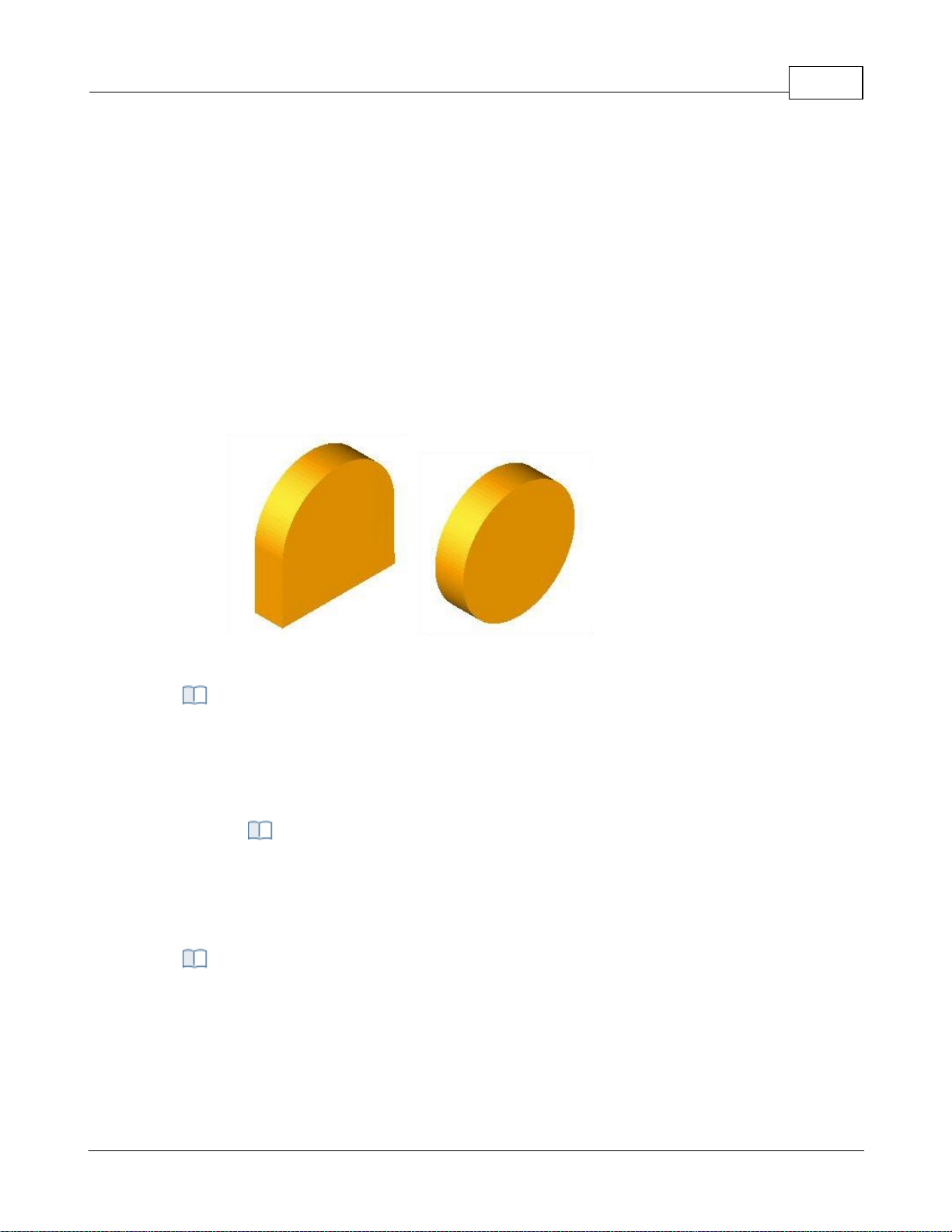
User Interface 88
This model is fast but suffers from some accuracy limitations near vertical walls. The
display quality of this simulation might also be insufficient for some applications
especially when simulating near vertical walls.
Polygonal Model
The Polygonal Model on the other hand is a high quality simulation model. This model
uses more accurate simulation algorithms at the expense of speed. The speed of this
simulation can be relatively slow when compared to the Voxel Model. Additionally only
the Polygonal Model of simulation can be used for 4 and 5 Axis simulations. The Voxel
Model is limited strictly to 3 Axis applications.
Note: * Thi s feature i s not a vail able in Xpress configurati on.
Here is an example of a cylinder stock model representation with Voxel and Polygonal
model.
Simulation Model - Voxel
Simulation Model – Polygonal
You can set the simulation mode to Distance or by Motion. Simulate by Motion simulates
the toolpath based on the number of go to motions in the generated toolpath. Simulate
by Distance uses a distance based approach.
Note: * Thi s feature i s not a vail able in Xpress configurati on.
Simulation Speed
You can control the speed of the simulation using the slider bar and the
Maximum display interval. When using Simulate by distance mode, the speed is
determined as # of Motions / Distance.
This setting is used to control the accuracy of display of the simulated model. You can
control the accuracy of the stock model by selecting from Standard, Medium or Fine. The
finer the stock model accuracy results in slower performance and increases the
simulation time.
Use Specified Simulation Spacing for Voxel Model
Simulation Mode
Simulation Accuracy
© 2024 MecSoft Corporation
Page 90
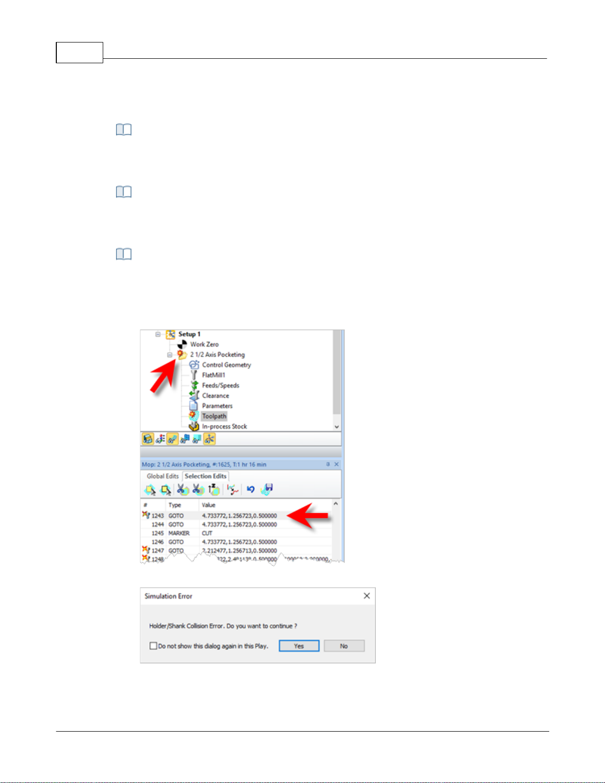
VisualCAD/CAM-MILL 2024 Reference89
When Voxel Model is selected (see Simulation Model above), you can also specify the
spacing for the Voxel model. Check the box and enter the Spacing distance desired.
Use this slider to adjust the Stock Model Transparency when the Simulate tab is selected
(i.e., when you are performing a cut material simulation).
Check this box to Remove Remnants During Simulation. Any disassociated stock will be
removed from the simulation.
Stop Simulation in Error
Check this box to pause the Simulation at each error flag. If enabled, a message will
display asking if you wish to continue with the simulation. Selecting Play will simulate to
the next error flag and then pause. etc.
Stop Simulation at Error Flag
Stop Simulation at Error Flag message
Disable Advanced OpenGL
Stock Model Simulation Display Transparency
Removal of Remnants
Additional Options
© 2024 MecSoft Corporation
Page 91
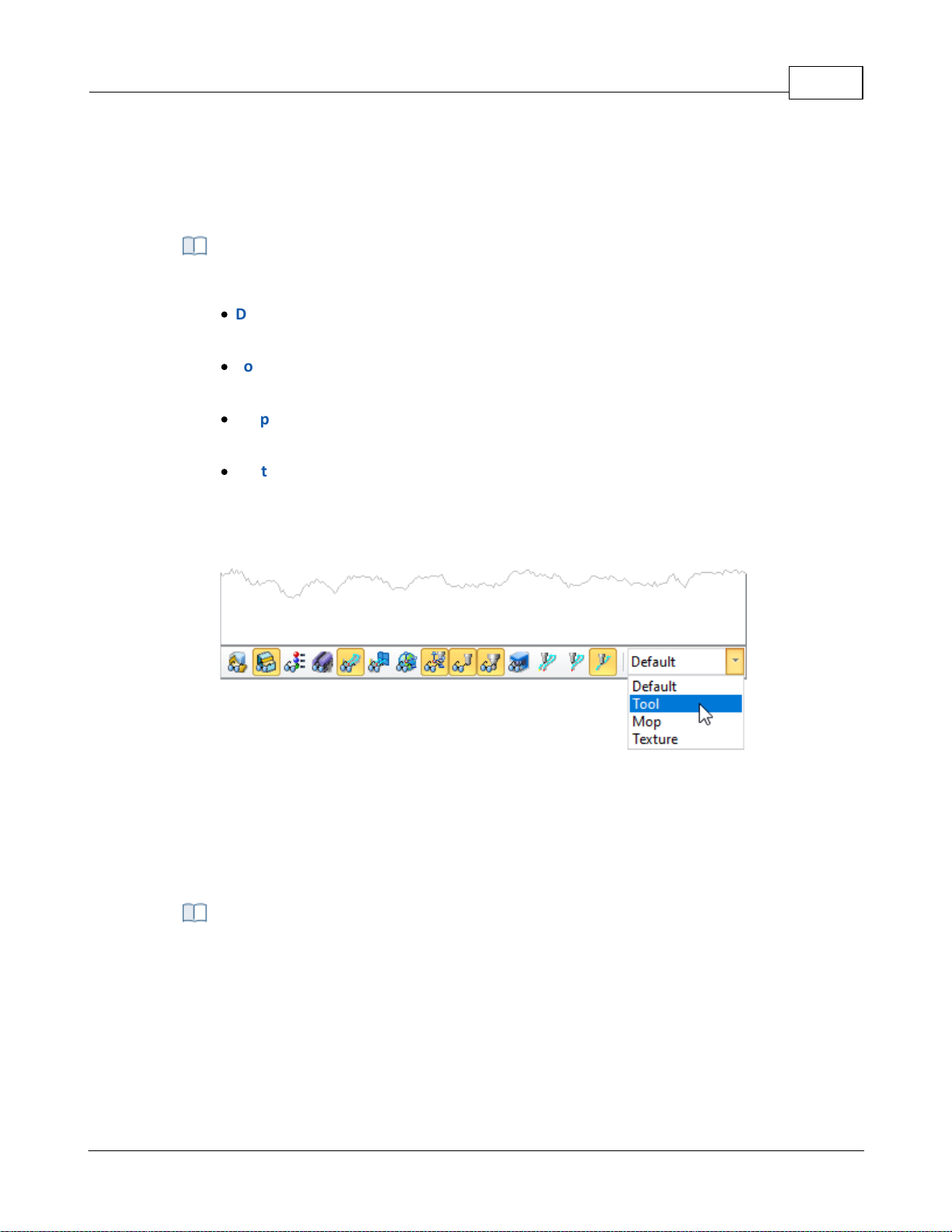
Check this box only if you have an older graphics card adapter that does not support
advanced OpenGL (i.e., OpenGL 2). Some older cards may only support OpenGL 1 for
example. If you experience graphics instability checking this box may help resolve the
issue.
Simulation Display State
Select how color is applied to toolpaths during simulations. Choose from the following:
·
Default: The CAM preferences for Stock Colors are applied. See the Stock tab in the
CAM Preferences dialog.
·
Tool: The Cut Material color assigned to the tool is applied. See the Create/Edit Tool
Dialog
·
Mop: The color properties of the Machining Operations (Mops) are applied. Right-click
on the MOp and select Properties.
·
Texture: The material texture defined in the Materials dialog is applied. Select
Materials from the Program tab.
To change the display state manually, go to the Simulate tab and adjust the Display State
menu located at the bottom of the Machining Browser as shown below.
User Interface 90
4.7.10 User Interface
From here you can set the various user interface options.
Dialog Box: CAM Preferences > User Interface
© 2024 MecSoft Corporation
Page 92
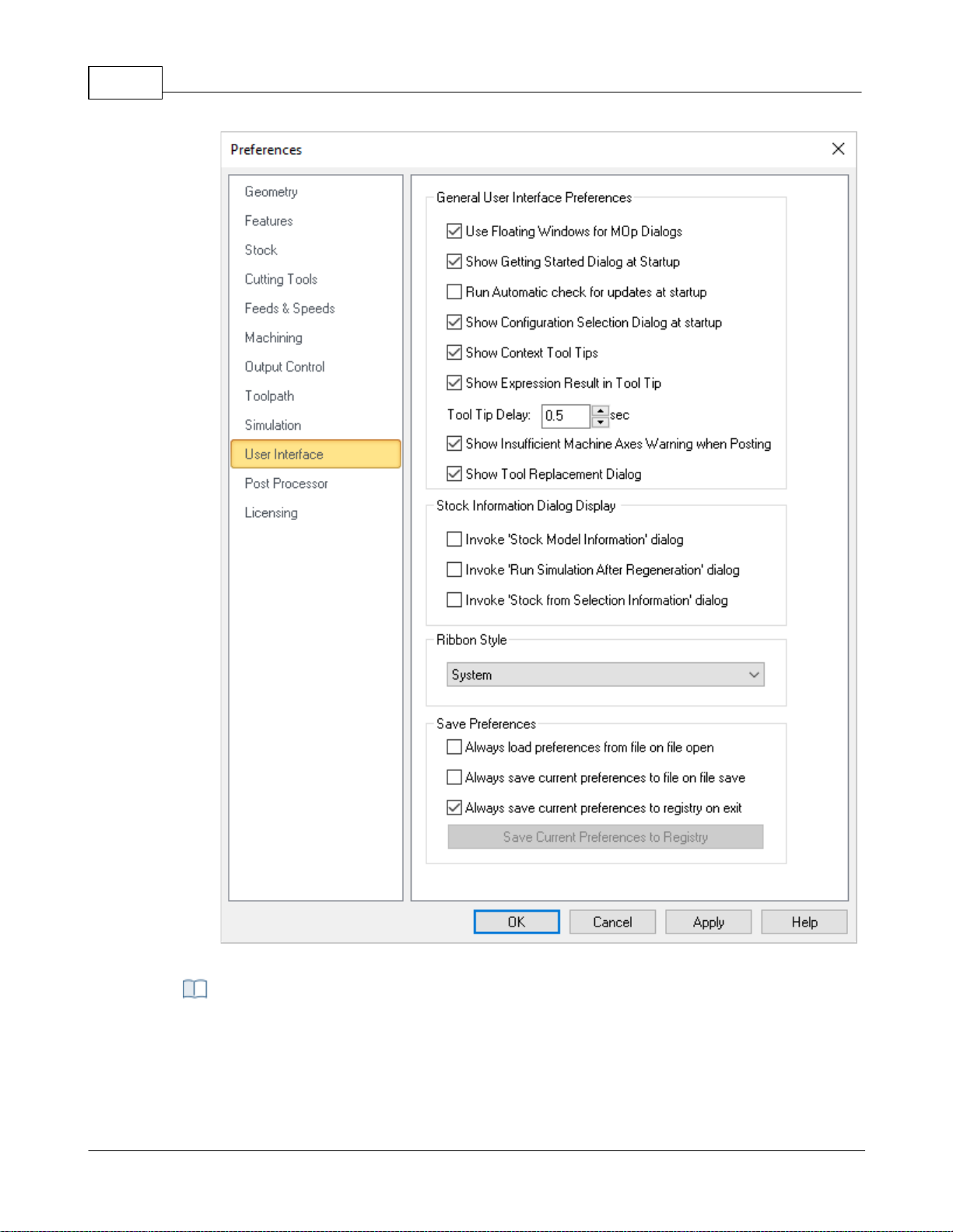
VisualCAD/CAM-MILL 2024 Reference91
Dialog Box: CAM Preferences > User Interface
User Floating Windows for Mop Dialogs
Selecting this option displays machining operation dialogs as a floating window where
the dialog appears on top of the Machining Browser. If the above option is unchecked
General User Interface Preferences
© 2024 MecSoft Corporation
Page 93
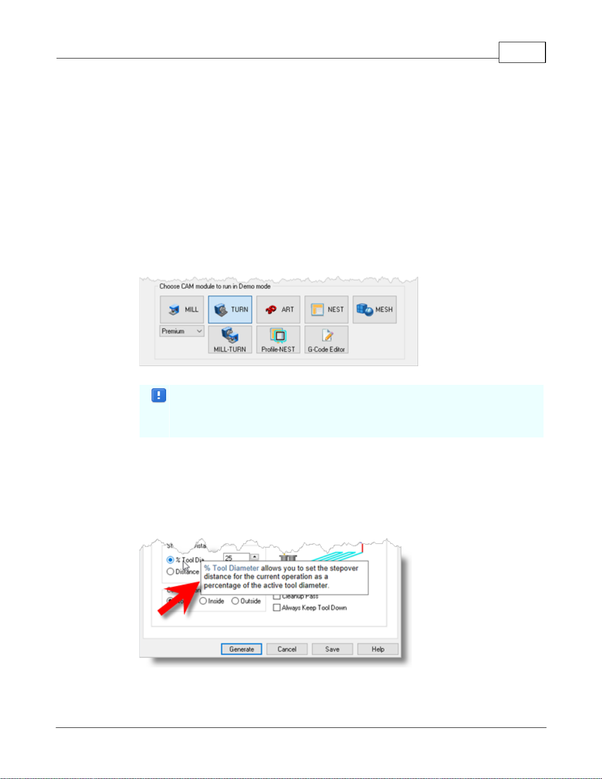
the machining operation dialog is docked and is displayed over the Machining Browser
window.
Show Getting Started Guide at startup
This displays Getting Started dialog at program startup every time the program is loaded.
This dialog provides quick access to resources on MecSoft's website.
Run Automatic check for updates at startup
Selecting this option automatically checks for product updates when VisualCADCAM is
loaded. This requires access to internet on the computer running VisualCADCAM.
Show Configuration Selection Dialog at startup
Selecting this option displays the product configuration dialog to run when the program
is loaded. User can select from the following MILL modules - Standard, Expert,
Professional and Premium.
Configuration Selection Dialog at startup
This dialog appears at startup when VisualCADCAM is running in demo mode.
Selecting a configuration loads VisualCADCAM and provides the features
available in the selected configuration.
Show context ToolTips
Check this box to display Context ToolTips when the mouse moves over a parameter in a
dialog. A definition of the parameter will pop-up automatically. Note that Context
ToolTips may not be available for ALL dialogs. You can also set the ToolTip Delay in
seconds. This is the amount of time it takes to display the Context ToolTip when the
mouse activate it.
Show Expression Results in Tooltip
User Interface 92
© 2024 MecSoft Corporation
Page 94
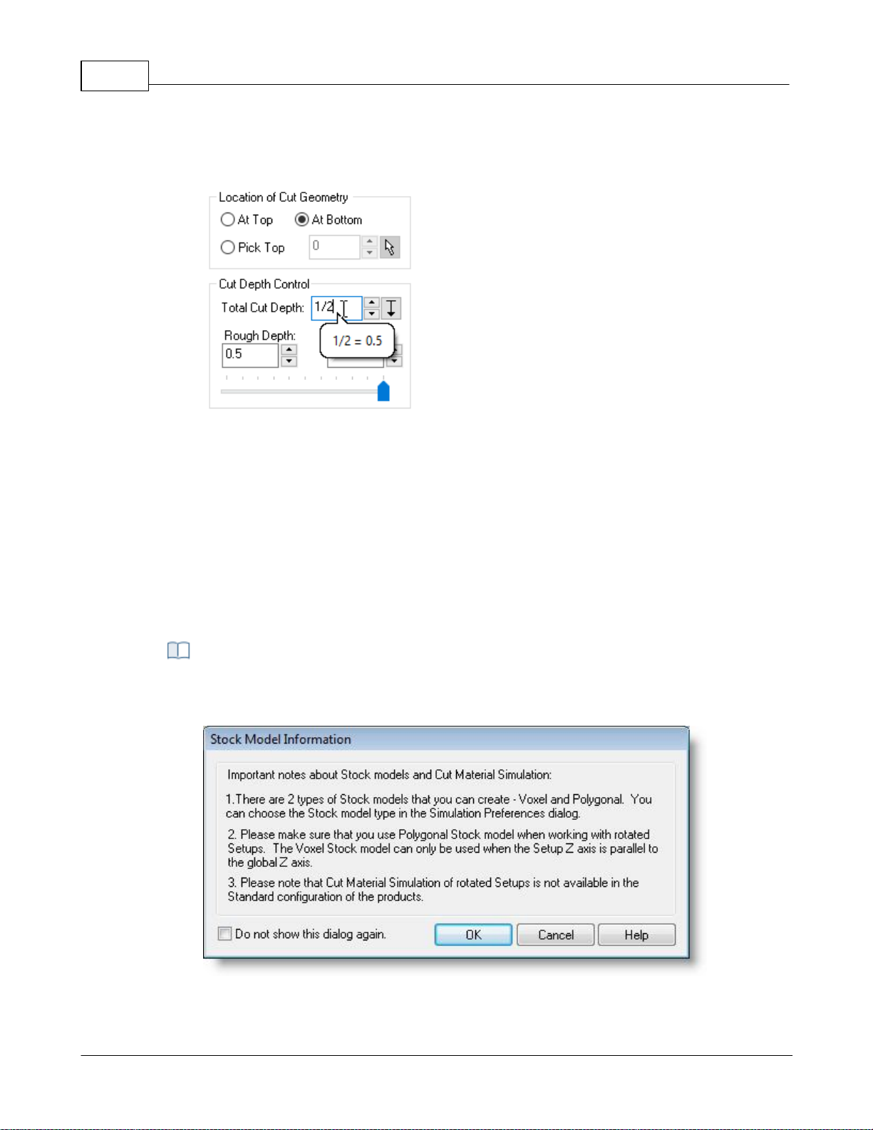
VisualCAD/CAM-MILL 2024 Reference93
You can enter expressions in any dialog field that expects a numerical value and the
value will be computed and entered automatically. Check this box to pop-up the results
of any expressions in a ToolTip balloon. An example is shown below.
Show Expressions in ToolTip
Show Insufficient Machine Axis Warning when Posting
With this checked, you will receive a warning message if the Machine Setup definition is
not set to the required number of axis for the operation being posted.
Show Tool Replacement Dialog
When you open a file that contains tool(s) whose names match a tool that is currently
loaded, a dialog asks if you wish to replace the currently loaded tools with the tools from
the file you are opening. You can check this box to replace tools by default and stop the
dialog from displaying.
Invoke 'Stock Model Information' dialog
The Stock Model Information dialog is displayed when a stock geometry is created.
Dialog Box: Stock Model Information
Stock Information Dialog Display
© 2024 MecSoft Corporation
Page 95
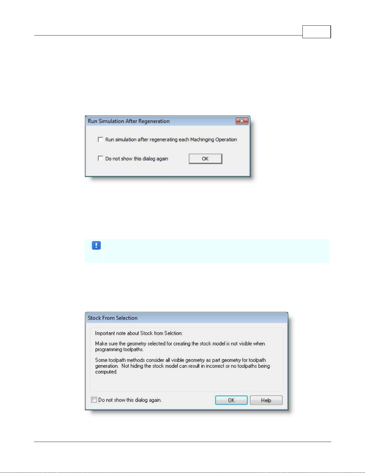
You can turn off this dialog by selecting Do not show this dialog again located on the
bottom of the message window.
To display this dialog during stock creation, select CAM Preferences > User Interface and
select Invoke ‘Stock Model Information’ dialog.
Invoke 'Run Simulation After Regeneration' dialog
This dialog is displayed when you regenerate a Setup or the Machining Job.
Dialog Box: Run Simulation After Regeneration
Run simulation after regenerating each Machining Operation
Selecting this option simulates every machining operation in the Setup after the
operation is regenerated. This is generally selected when a re-roughing operation is part
of a Setup as it requires the in-process stock of the previous roughing operation to
generate the re-roughing toolpath.
This process would take longer processing time to regenerate all operations in a
Setup depending on the system resources and simulation preferences.
To display this dialog when regenerating a Setup, select CAM Preferences > User
Interface and select Invoke ‘Run Simulation after Regeneration’ dialog.
Invoke 'Stock from Selection Information' dialog
This dialog is displayed when creating Stock geometry using Stock from Selection.
Dialog Box: Stock from Selection Information
User Interface 94
© 2024 MecSoft Corporation
Page 96
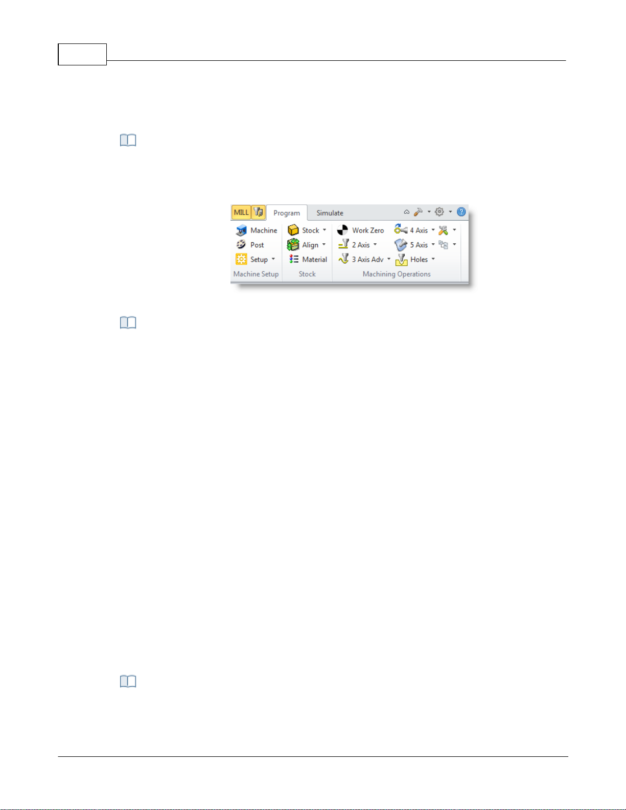
VisualCAD/CAM-MILL 2024 Reference95
To display this dialog again when creating Stock from Selection select CAM Preferences >
User Interface and select Invoke ‘Invoke Stock from Selection Information’ dialog.
This allows the selection of different themes that changes how the Browser windows
appear. The borders, colors, highlighting, and shadowing of standard buttons, dialogs,
and windows are controlled by which theme is selected.
Example Ribbon Style: Office 2010 Silver
Always load preferences from file when opening a new file
Check this box if you wish to always load CAM Preferences from the file you are opening.
Remember, however, that your current settings including your selected post is subject
to be being changed.
Always save current preferences to file on file save
Check this box if you wish to always save the current CAM preferences to the file on file
save. Remember, however, that your current settings including your currently selected
post will replace those preferences that were in the current file originally.
Always save current preferences to registry on exit
Check this box if you wish to always save the current CAM preferences to the Windows
registry when you exit your MecSoft CAM plugin. This will ensure that your current CAM
settings will always be used when starting a new file.
Save Current Preferences to Registry
If you have your preferences set the way you want them and do not want them top
change, select this button to save the current preferences to your Windows registry.
Doing this will force them to be loaded when you create new files.
Ribbon Style
Save Preferences
4.7.11 Post Preferences
These preferences relate to posting toolpath operations to gcode files.
CAM Preferences > Toolpath
© 2024 MecSoft Corporation
Page 97
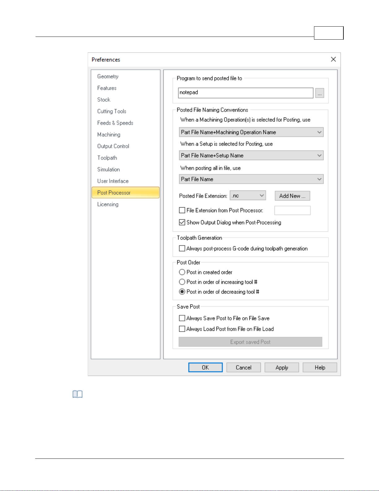
User Interface 96
CAM Preferences > Post
This feature allows you to specify a program to display the posted file. This could be a NC
editor or a text editor like Notepad.
Program to send the Posted file to
© 2024 MecSoft Corporation
Page 98
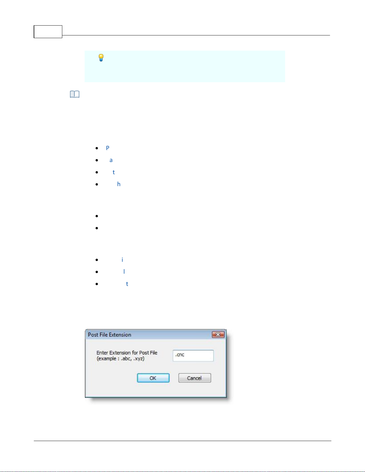
VisualCAD/CAM-MILL 2024 Reference97
You could also have this point to your control software’s
executable file and VisualCAM will automatically launch this
application when the machining operations are post processed.
This allows you to set rules for posted file name when post processing machining
operations.
When a machining operation is selected for posting you can set the output file name
from one of the following options.
·
Part File Name + Machining Operation Name
·
Part File Name + Setup Name + Machining Operation Name
·
Setup Name + Machining Operation Name
·
Machining Operation Name
When a setup is selected for posting you can set the output file name from one of the
following options.
·
Part File Name + Setup Name
·
Setup Name
When Machining Job is selected to Post All, you can set the output file name from one of
the following options.
·
Part File Name
·
Part File Name + First Setup Name
·
First Setup Name
Posted File extension
You can select a posted file extension from the list or add an extension to the list by
selecting Add new button. This displays the Post File Extension dialog shown below
where you can specify a new file extension and click OK.
Dialog Box: Post File Extension
The new file extension is now set as your posted file extension automatically.
Posted File Naming Conventions
© 2024 MecSoft Corporation
Page 99

User Interface 98
By default VisualCAM performs interactive post-processing. That is, when you select a
toolpath for post-processing, VisualCAM launches the post-processor and waits for it to
complete. You can also turn off the display of the output dialog (post and save dialog).
During interactive post-processing, VisualCAM launches the NC editor to view the output
file. You can specify a different NC editor to use. See Program to send the Posted file to
above for doing this.
File Extension from Post Processor
Check this box to "pull" the posted g-code file extension from the Legacy Post-Processor
(*.spm) file. This ensures that whichever post that you use, your posted g-code file will
match the file extension defined in the active post. Note: You must edit your legacy post
and set the Output File Extension value from the General tab in the Post-Processor
Generator.
Show Output Dialog When Post Processing
Check this box to always display the Post & Save As file dialog when you select Post from
an operation (Mop), Setup or Machining Job.
Always post-process G-code during toolpath generation
Your G-code is stored with your CAM file so that the latest G-code is always available to
you when you open a file. Uncheck this box if you do not want new G-code generated
every time you generate a toolpath operation.
Use these options to implement post priority.
Post in created order
Select this option to post operations in the order that they appear in the machining Job
tree.
Post in order of increasing tool #
Select this option to post operations in the order of increasing tool number. The
operation with the lowest tool number is posted first.
Post in order of decreasing tool #
Select this option to post operations in the order of decreasing tool number. The
operation with the highest tool number is posted first.
Always save post to file on file save
The current post will be saved to the file when it is saved. CAUTION: The file's Current
post will be replaced.
Always load post from file on file load
Toolpath Generation
Post Order
Save Post
© 2024 MecSoft Corporation
Page 100
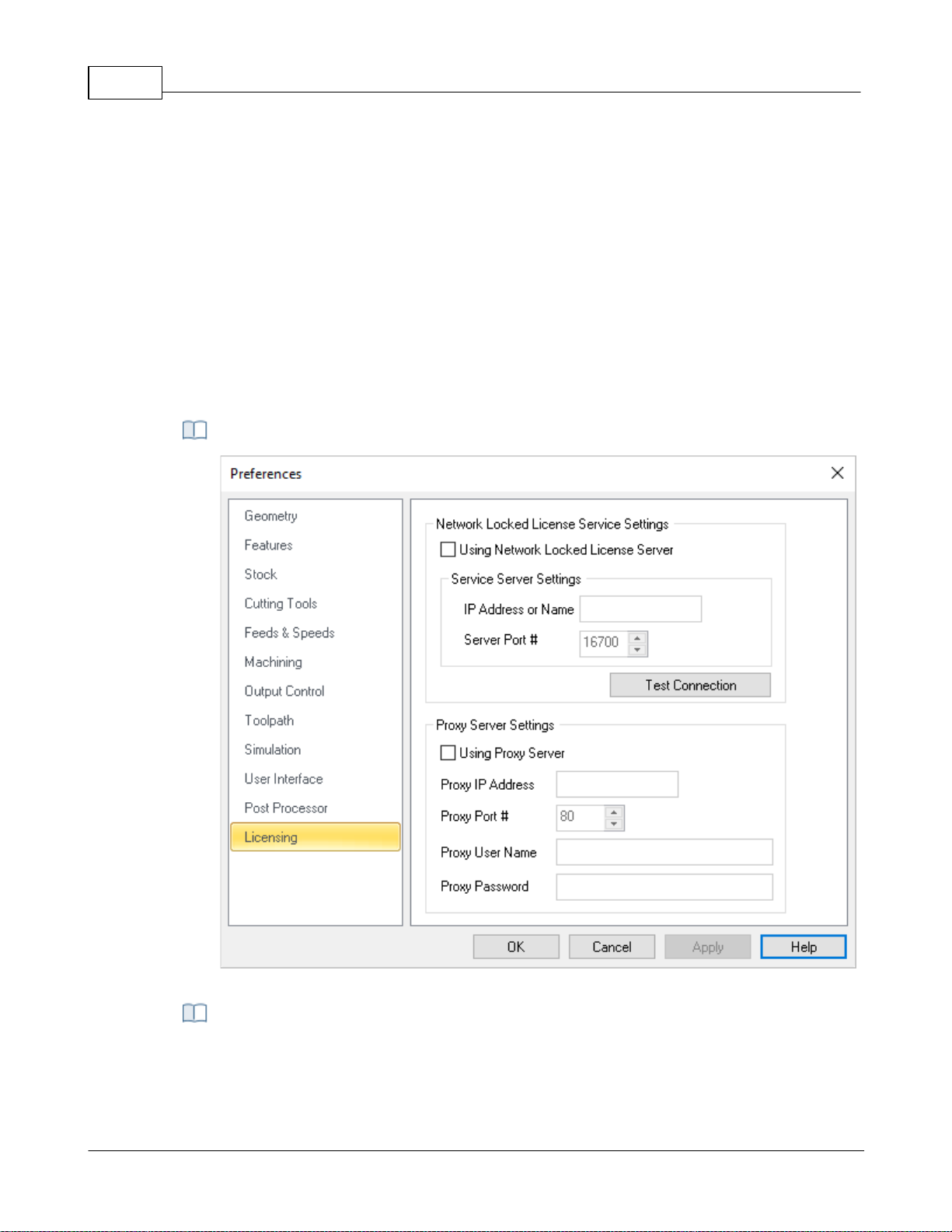
VisualCAD/CAM-MILL 2024 Reference99
The post defined in a file you are open will become the new Current post post selected
in the Post-processor options dialog. CAUTION: The post in the file you are opening will
be replaced. If this is not desired, close and do not save the file.
Export Saved Post
Use this option to save the Current post in the active file to a post definition file name
ending in *.spm
Dialog Box: License Preferences
Network Locked License Service is a security process required when a computer on a
network tries to connect to the server in order to use its resources. If the user's identity
has been stored by the server, entering a valid username and password completes the
4.7.12 Licensing
This dialog allows you to set Licensing Preferences for using a Proxy Server and/or a LAN Daemon
(for Network Licenses). This information would be provided by your network administrator.
Dialog Box: License Preferences
Network Locked License Service Settings
© 2024 MecSoft Corporation
 Loading...