

Page 1
Assembly and Installation of
Helixa-i
Helixa-xt
the Helixa
Precision Torque Tester
431-439-05
June 2015
Page 2

Important
It is essential that you familiarise yourself with the contents of this Assembly and
Installation Manual, and the separate Guide to Safe Use of Mains Powered Test Systems
before attempting to operate your Helixa Test System.
Control console warranty
The Helixa-xt console is pre-configured at Mecmesin for use with the Helixa-xt stand.
With the exception of the Advanced Builder Option, which requires a configuration
change to the console, any unauthorised changes to the console configuration and set-up
will invalidate the warranty.
The 24-month end-user warranty for the Helixa-xt console itself is with a third party.
Please contact your local Mecmesin agent for assistance with this warranty.
The Microsoft® Windows® Embedded operating system for the Helixa-xt console is preinstalled and licensed by Mecmesin and supplied with an End User License Agreement,
and Certificate of Authenticity.
Scope
This reference manual covers the Helixa-i and the Helixa-xt range of test stands. For
programming, refer to these manuals:
431-382 Emperor Force and Torque Testing Software, Operator Manual
431-389 Emperor™ Programming for Mecmesin-xt Force and Torque Test Systems
2015 © Mecmesin Ltd, supplied with Mecmesin test systems and not for redistribution
Part no. 431-439-05
ii Mecmesin Assembly and Installation of the Helixa Precision Torque Tester
Page 3

Contents
1. Items Supplied with the Test Stand 1
1.1 Helixa-i test stand 1
1.2 Helixa-xt test stand (additional) 1
2. Installation 2
2.1 Unpacking the stand 2
2.2 Lifting the test stand 2
2.3 Locating the stand 2
2.4 Releasing the crosshead 2
2.5 Mains power supply 3
3. Assembly and Stand Controls 3
3.1 Fitting the feet to the stand 4
3.2 Stability and bench-mounting 4
3.3 Fitting the top mass platen 4
3.4 Fitting a torque cell to the crosshead 5
3.5 Swapping Helixa torque cells (HTCs) 6
3.6 Attaching grips and fixtures 6
3.7 The Helixa front control panel 6
3.7.1 Emergency stop button 6
3.7.2 Jog buttons 7
4. The Counterbalance Mechanism 8
4.1 Adding counterbalance weight, and applying top-load 9
4.2 Securing the counterweights 9
5. Helixa-xt : Fitting the Control Console 10
5.1 Fitting the console to a Helixa-xt 10
5.2 Connecting the console power lead and RS232 lead 11
5.3 Switching on the Helixa-xt system 11
5.4 Connecting other devices 11
5.5 The touch screen console 12
5.6 Operators and Master users 13
Assembly and Installation of the Helixa Precision Torque Tester Mecmesin iii
Page 4

6. Helixa-i : Installing and Connec ting with the Emperor ™ software 14
6.1 Helixa-i: Installing Emperor Software on Your PC 14
6.1.1 Minimum system requirements 14
6.1.2 Access to data folders 14
6.2 Connecting the power lead and USB lead 15
6.3 Switching on the Helixa-i system 15
6.4 Starting Emperor 15
7. Precision Alignment 17
7.1 Procedure 17
Appendix A System Specifications 20
Appendix B EC Declarations of Conformance 22
Appendix C Microsoft® Windows® Embedded Standard 7 Licensing 24
End User Licence Agreement (EULA) 24
Certificate of Authentication (COA) 24
iv Mecmesin Assembly and Installation of the Helixa Precision Torque Tester
Page 5

1. Items Supplied with the Test Stand
1.1 Helixa-i test stand
• The Helixa test stand
• Appropriate mains cables for test stand and console (Helixa-xt)
• 4 × rubber feet
• 4 × bench-securing lugs
• 4 × attachment screws for either feet or lugs
• Top mass platen and fixings
• Balance hanger for external weights
• Allen keys
• Alignment tool
• CD with software and manuals for backing up or running on a PC
• Manual: A Guide to the Safe Use of Mains Powered Test Frames
1.2 Helixa-xt test stand (additional)
• Console fitted with arm, power cable and RS232 cable
• Torx wrenches for fitting the console to the stand.
Assembly and Installation of the Helixa Precision Torque Tester Mecmesin 1
Page 6

2. Installation
2.1 Unpacking the stand
When you first receive the stand please check that there is no obvious damage to the
packaging. If there is any sign that the packaging or the test stand itself has been
damaged, please contact Mecmesin or your authorised distributor immediately. Do not
use the stand until you have done so.
We strongly recommend that the packaging is kept, as this can be useful if the machine
needs to be returned for calibration.
Section 1 lists items that should be included with your test stand. Please contact
Mecmesin or your authorised distributor if any items are missing or damaged.
2.2 Lifting the test stand
The unpackaged weight of the test stand is given in the Specification table at the back of
this manual. Do not try to lift heavy loads unaided. Use suitable lifting equipment if
necessary.
2.3 Locating the stand
The test stand must be positioned on a suitable, level, stable work surface.
2.4 Releasing the crosshead
For safety in transit the internal counterbalance weights are secured internally. (See
Section 4.2 ‘Securing the counterweights’ for instructions.)
Release the securing lever on the right hand side of the column by half a turn
anticlockwise.
The crosshead can now be raised and lowered manually, or by using the heightadjustment knob on the left, and secured with the lever on the right side of the column.
2 Mecmesin Assembly and Installation of the Helixa Precision Torque Tester
Page 7
2.5 Mains power supply
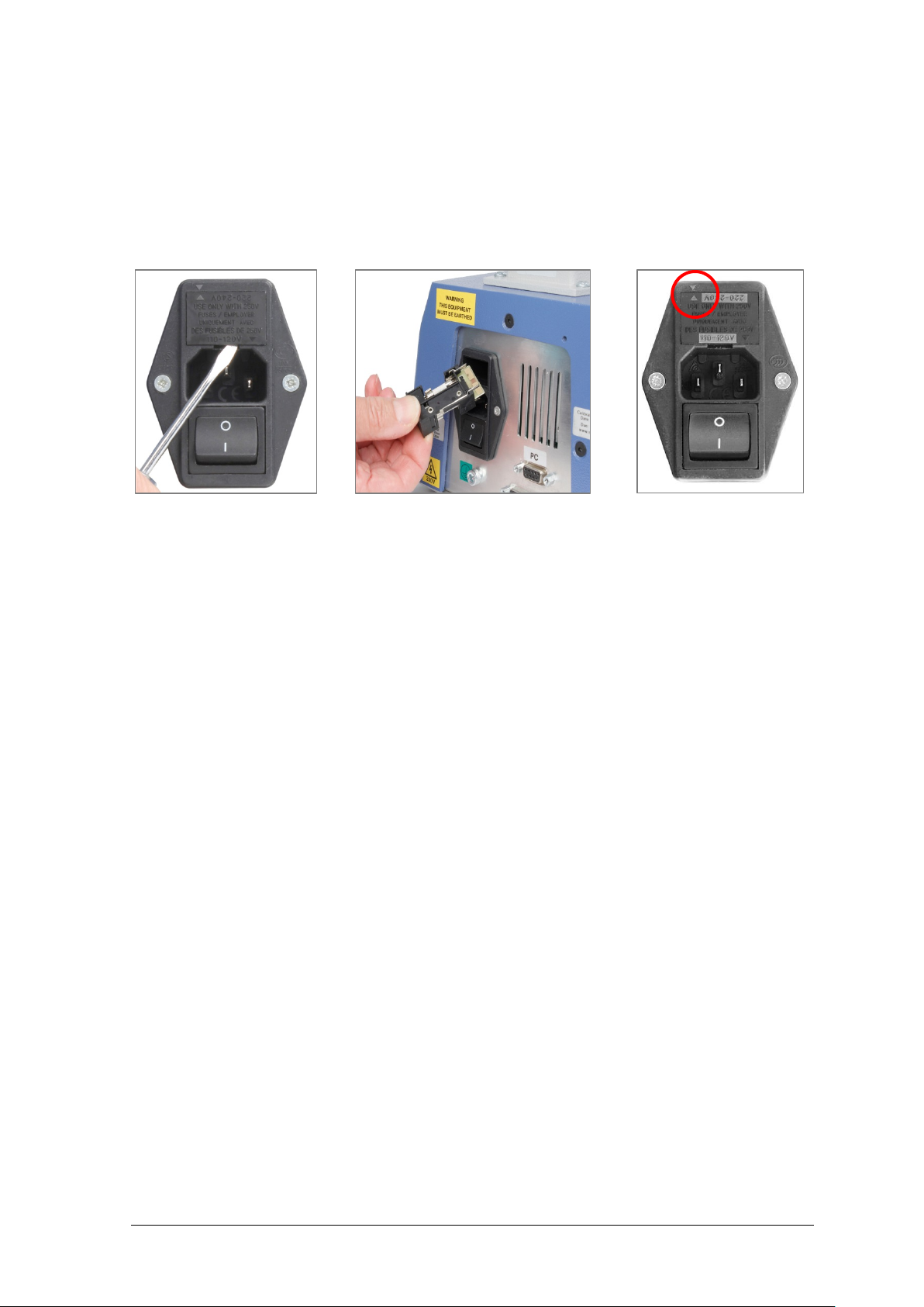
Mecmesin test stands can be used on 110–120 or 220–240 V ac 50-60 Hz supplies. The rear
fuse carrier will be set for your local requirement, but is reversible, so should you replace
a fuse, the correct local voltage must be selected. The voltage that is selected is the one
where the arrows meet (the power inlet is inverted for some test stands):
R emoving the fuse carrier Carrier removed to replace fuse Selector set to 220-240 V
Assembly and Installation of the Helixa Precision Torque Tester Mecmesin 3
Page 8
3. Assembly and Stand Controls
3.1 Fitting the feet to the stand
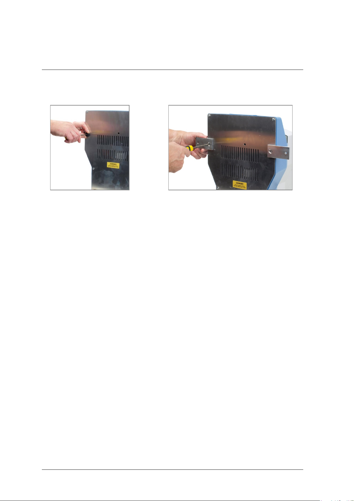
Fitting rubber feet … … or bench-securing lugs, to the base of the Helixa
The Helixa is supplied with rubber feet. Lay the stand carefully on its back, and fit the
four rubber feet to the base of the stand. Please note: The Helixa is heavy and it is
recommended that two persons move the stand for this operation. Handle the Helixa
only by its base and column, not the crosshead or spindle deck.
3.2 Stability and bench-mounting
Helixa-xt as a free-standing unit conforms to BS EN 61010-1:2010 section 7.4(a)
requirements for stability. However, it is recommended that the control console remains
mounted at the mid-point of the column.
If you require the console unit to be mounted higher than the mid-point of the column,
and/or use additional weights in the mass platen or external rear hanger, then fit the four
bench-securing lugs to the Helixa-xt or Helixa-i for complete stability (shown above).
3.3 Fitting the top mass platen
Secure the top mass platen to the top of the Helixa torque cell (HTC) using the two M6
countersunk screws supplied.
4 Mecmesin Assembly and Installation of the Helixa Precision Torque Tester
Page 9
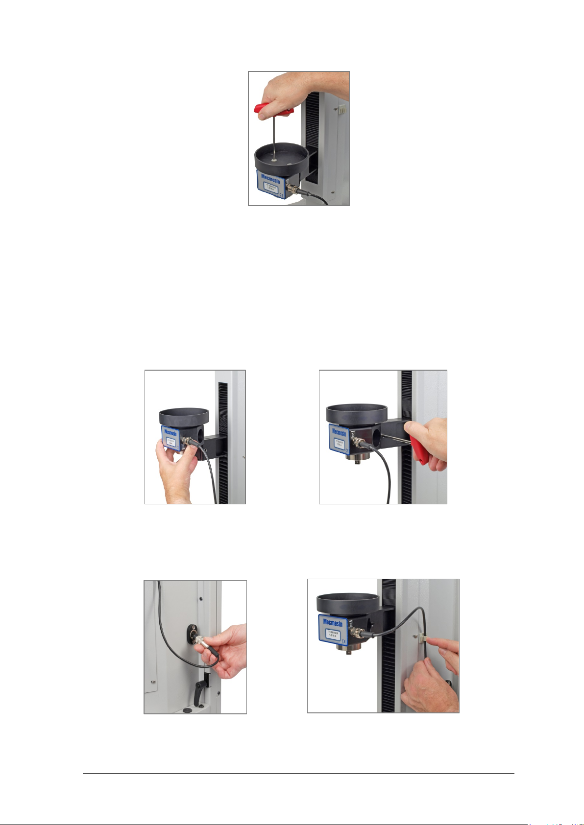
Attaching the top mass platen to the torque cell
3.4 Fitting a torque cell to the crosshead
Ensure the stand is switched off.
Slide the HTC down onto the dovetail bracket at the front of the crosshead. Slide it fully
downwards against the stop, and tighten the securing screw using the appropriate Allen
key. Do not over-tighten.
Slide the HTC onto the dovetail … tighten securely …
Align the electrical connector of the HTC with the socket on the test stand. Gently push
the connector to locate, then tighten the knurled locking ring to secure it.
connect the torque cell secure the cable, and adjust free length
Assembly and Installation of the Helixa Precision Torque Tester Mecmesin 5
Page 10
Secure the torque cell cable using the clip on the right hand side of the column, and adjust
it so that there is no tension through the travel of the crosshead.
3.5 Swapping Helixa torque cells (HTCs)
You can swap HTCs by simply disconnecting one cell and fitting another. First, return to
the Main Screen and switch off the stand before unplugging the HTC. When the new cell
has been connected, switch the stand on again, and after a few seconds the new HTC will
be automatically recognised. The Helixa will read in the new cell’s range, serial number
and calibration status.
3.6 Attaching grips and fixtures
Grips and other holding fixtures are usually paired, with one being attached to the main
spindle drive, and the other to the torque cell. Fixtures on the main spindle have a selfcentring fitting and four screws, whilst the torque cell has a square drive attachment.
Important: very low capacity torque cells are very sensitive and can be damaged easily
by inadvertent overload. Take great care to engage and withdraw fixtures perpendicular
to the cell and without any twisting movement.
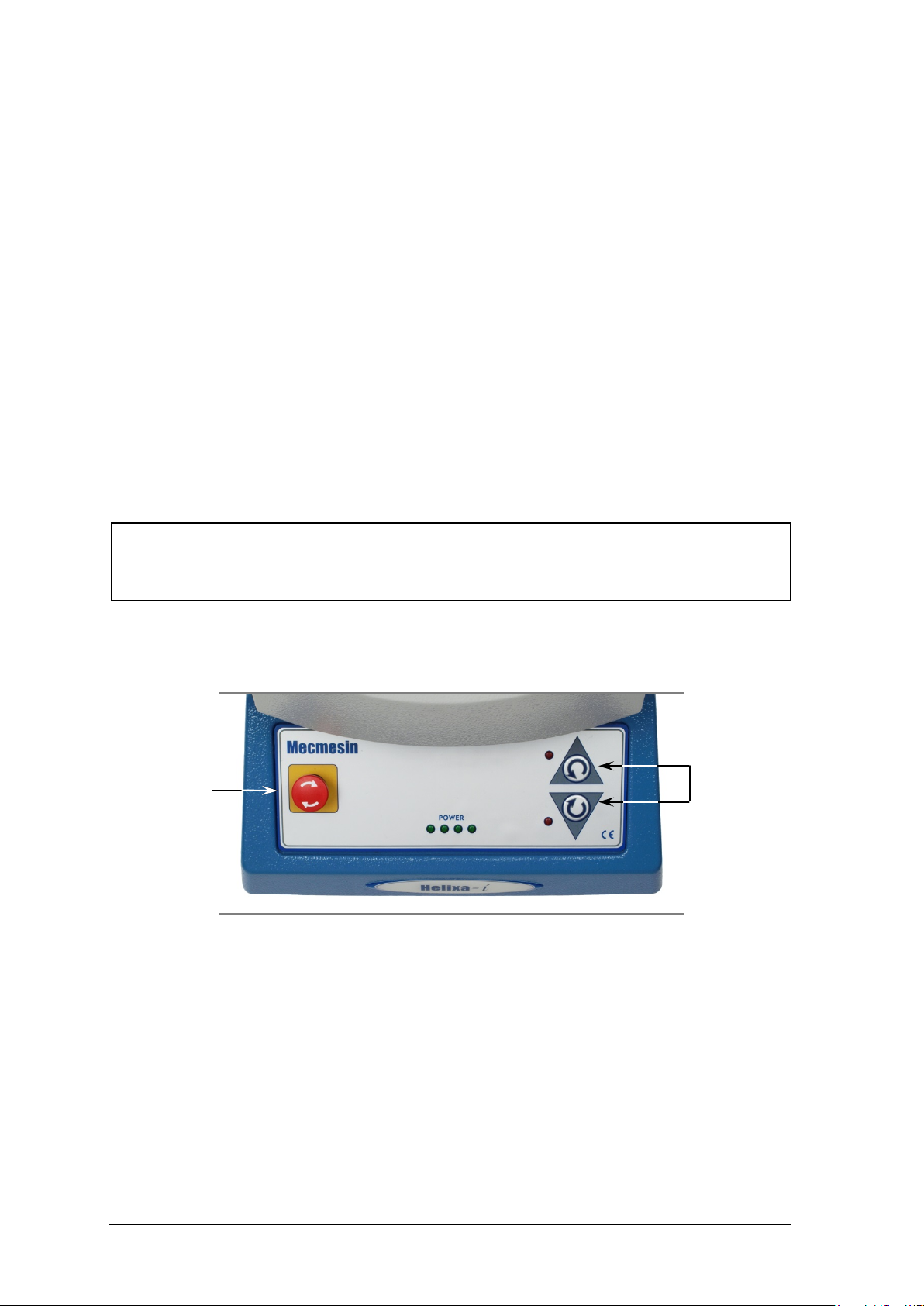
3.7 The Helixa front control panel
Emergency stop
The Helixa front control panel
3.7.1 Emergency stop button
The emergency stop button will stop all movement of the drive spindle. Pushing the
button will override all other controls. When pressed, the button stays latched down,
preventing any movement of the motor. To re-set the button, rotate it about 30 degrees
clockwise.
Jog buttons
6 Mecmesin Assembly and Installation of the Helixa Precision Torque Tester
Page 11

3.7.2 Jog buttons
Jog buttons are used to position the main spindle’s rotation, so that samples can be
secured. These buttons are replicated in the Emperor software, either on the console
(Helixa-xt) or the controlling PC (Helixa-i). The two sets of buttons function in different
ways.
Stand jog buttons speed Software jog buttons speed
Quick Test
Program Test
Advanced Test
Factory set fixed rate Jog speed increments or decrements each
time the jog button is pressed
Factory set fixed rate Rate set in Program test set-up > Test Settings
Factory set fixed rate Rate as set in Set-up > Preferences
Assembly and Installation of the Helixa Precision Torque Tester Mecmesin 7
Page 12
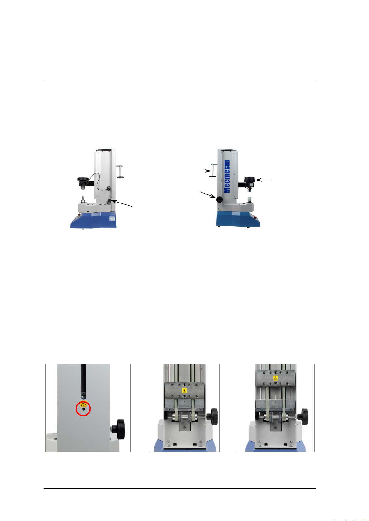
4. The Counterbalance Mechanism
The Helixa moving crosshead is counterbalanced by a system of weights. In this way, the
entire weight of the crosshead, HTC, fixture and sample part to be held, can be finely
counterbalanced. This may be required so as not to interfere with measuring the torque
on (for example) a rising screw thread, or conversely, to apply a specific downwards
force during torque testing, by the addition of weights to the top mass platen.
balance hanger
crosshead height
adjustment knob
crosshead height
securing lever
top mass platen
(shown with
weights added)
The large black adjustment knob on the left of the column can be used to raise and lower
the crosshead. The crosshead can also be moved by hand, and can be fixed in place using
the lever on the right of the column.
Internally, sliding counterweights operate. The two parts may be connected or separated
to apply all of the weight (2.25 kg), or only the upper weight (1.5 kg). The hanger without
weights adds a further 200 g.
• To reduce this counterbalance by one-third, insert an Allen key through the hole in the
back cover, which aligns when the crosshead is at its highest extent. Loosen the screw
until you feel the counterweights separate, by pressing down on the crosshead.
• To reconnect the two counterweights, raise the crosshead to its highest position, and
retighten the connecting screw.
Normal view, counterweight Back cover removed Counterweights separated
connecting screw cir cle d
8 Mecmesin Assembly and Installation of the Helixa Precision Torque Tester
Page 13
The counterweights are attached to two drive belts whose tension can be adjusted for
freedom of movement.
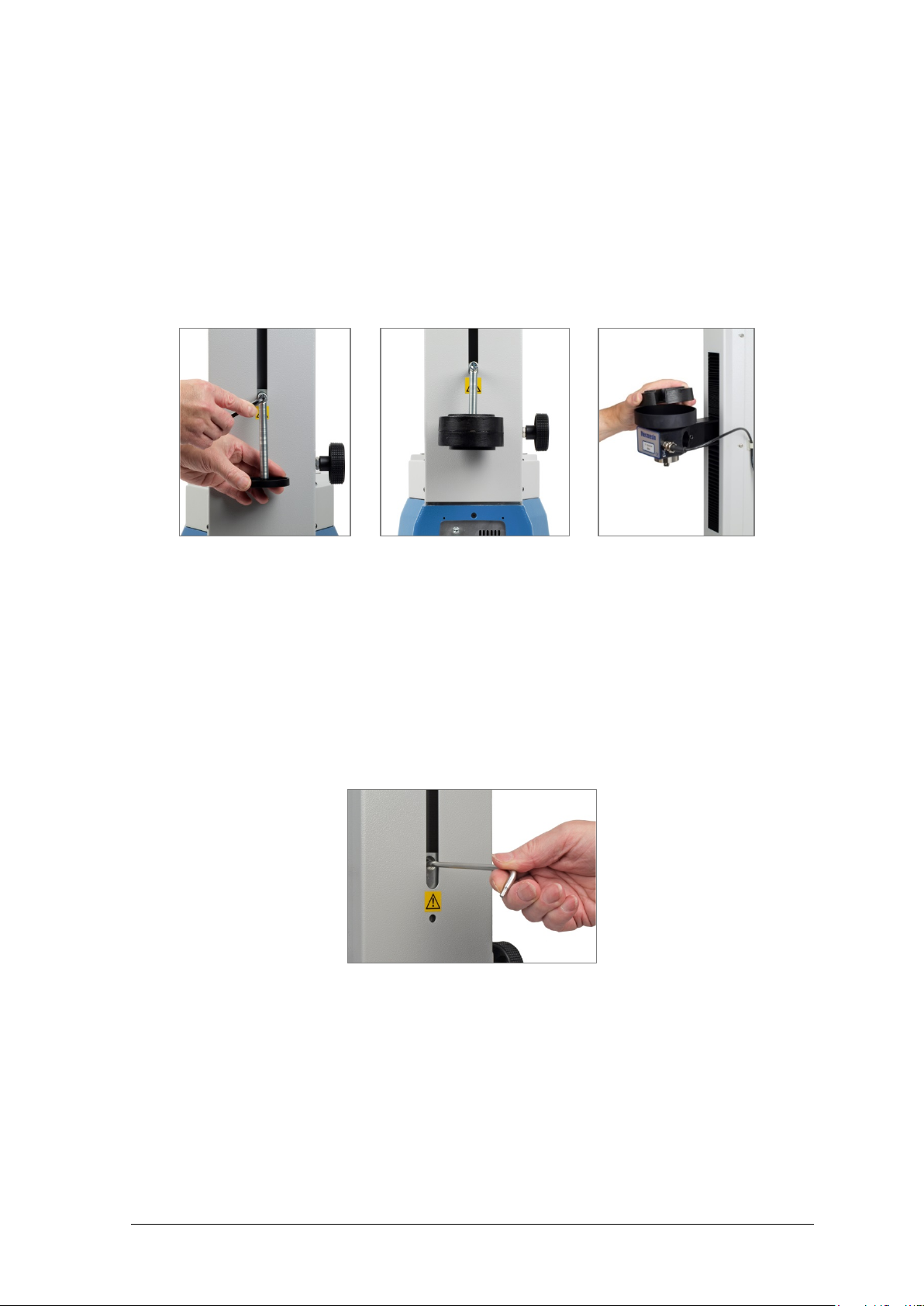
4.1 Adding counterbalance weight, and applying top-load
A balance hanger can be screwed into the rear weight, for additional weights to be
suspended. The moving crosshead itself has a mass platen for the addition of specific
weights. In combination, the required balance or load can be achieved.
Attach the balance hanger Suspend additional weights Apply top-load mass
4.2 Securing the counterweights
For safety in transit, the main counterweights inside the column are always secured, and
will need to be released during installation. Ensure the release lever is locked to prevent
immediate movement. Using an Allen key, release the grub screw through the hole in the
weights, visible at the base of the long central slot. Release the lever to move the
crosshead using the wheel on the left of the column.
Assembly and Installation of the Helixa Precision Torque Tester Mecmesin 9
Page 14
5. Helixa-xt : Fitting the Control Console
5.1 Fitting the console to a Helixa-xt
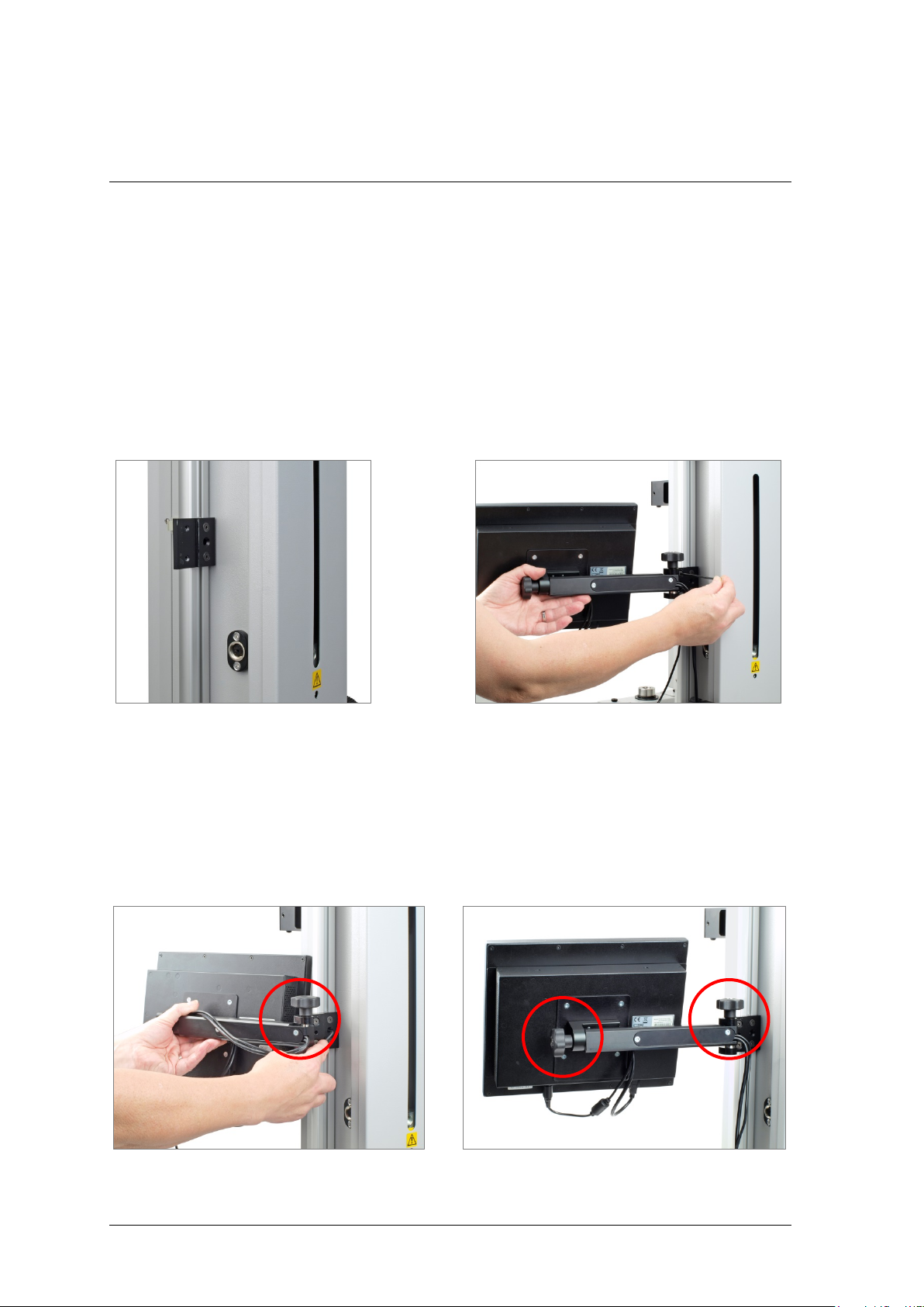
The console is supplied assembled onto an arm and bracket. This needs to be attached to
the black mounting plate on the side of the column, with the supplied tamper-resistant
Torx screws, using the appropriate Torx wrench provided. Note: Do not use any other
tools other than those provided.
Support the console with one hand and, with the top screw held in place by the supplied
Torx wrench, locate the bracket on the mounting plate and engage the screw, as shown
below. When almost tight, fit the lower screw. Tighten both, and release the console.
The console mounting plate Fix the upper Torx screw first
Adjust the console height by slackening the grub screw through the hole between the
fixing screws as shown below, whilst supporting the console. Re-tightening at the
required height. The angle and rotation of the console can also be adjusted. Slacken the
appropriate knob and reposition the bracket, or rotate the arm onto alternative sprungpin locations. Retighten each knob firmly so that the console does not move when the
screen is pressed.
Adjust the console height Adjust tilt and swing
10 Mecmesin Assembly and Installation of the Helixa Precision Torque Tester
Page 15
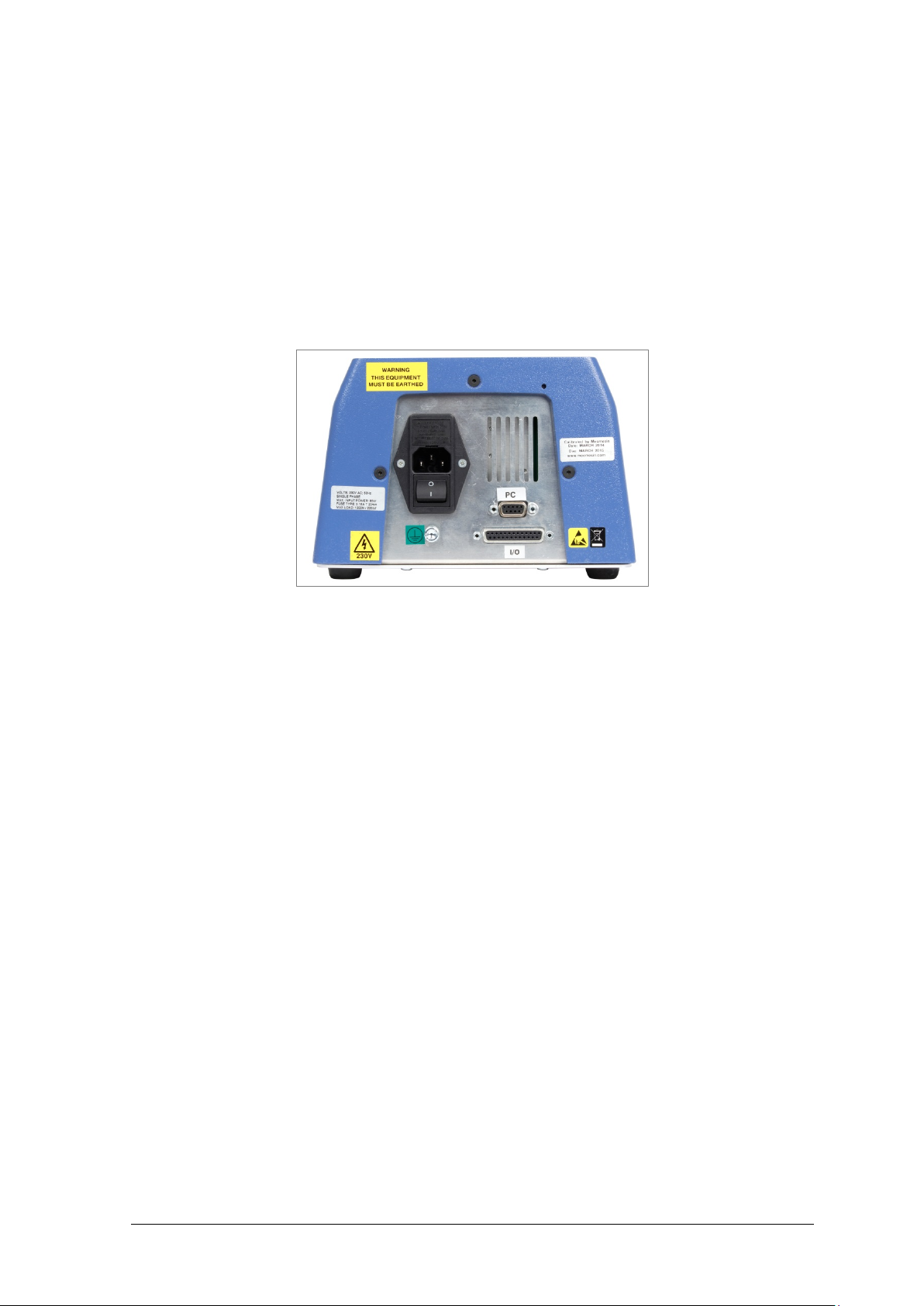
5.2 Connecting the console power lead and RS232 lead
The console is powered from a separate universal supply plugged into a mains socket.
Caution: use only the mains adaptor supplied by Mecmesin, do not use any other type.
The power lead and data cable will already be connected—check that they are firmly
fitted to the console. Plug the power adaptor into a suitable socket. Plug the data cable
into the 9-way socket labelled ‘PC’ on the rear of the Helixa. Normally it will not be
necessary to remove the data cable from socket COM1, but should this be required,
return the console to the front screen display before removing the RJ50 connector.
Helixa rear panel. Plug the data cable into the socket marked ‘PC’.
5.3 Switching on the Helixa-xt system
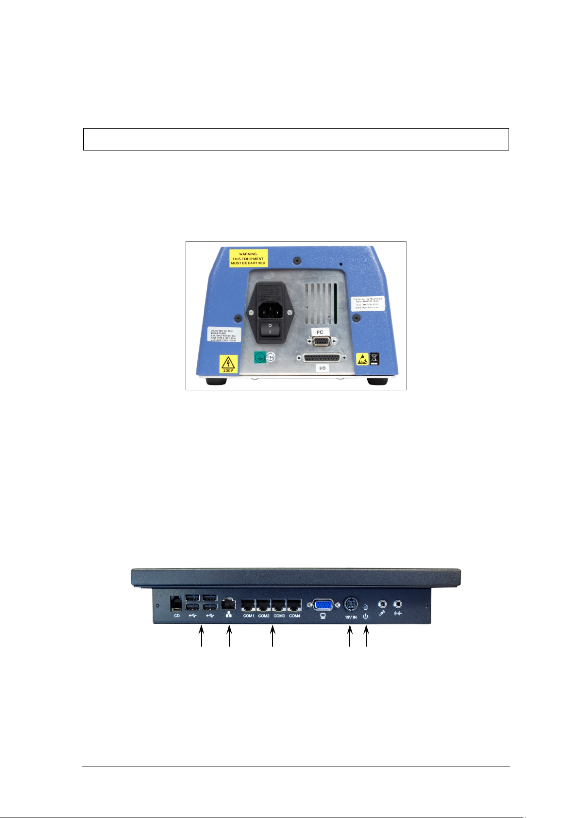
Switch on the test stand using the main switch located on the rear panel. Four green
power lights (LEDs) on the front panel will illuminate.
Switch the touch screen console on by pressing the small on/off switch located on the
underside of the console (shown below) to the right of the power lead. After a few
seconds the initial login screen will be displayed.
comms
on/off switch power in USB sockets network
5.4 Connecting other devices
Connect printers or other device using the USB sockets on the console underside.
Assembly and Installation of the Helixa Precision Torque Tester Mecmesin 11
Page 16
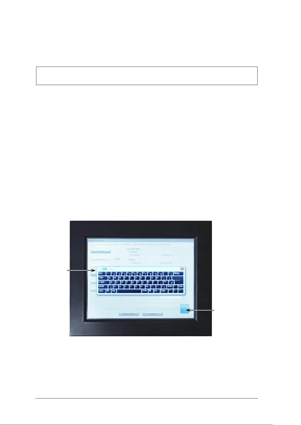
5.5 The touch screen console
The touch screen is used to control the Emperor-xt system.
Please note that this Windows computer does not contain an internal battery. If power
to the system is interrupted, unsaved data will be lost.
You can select operations and options by pressing or tapping on the relevant button on
the touch screen with a finger or a stylus. In the bottom right of any screen layout
requiring typed entry, there is a keyboard icon. Touch this, and a floating keyboard
appears so you can type in numbers or text. If this obscures an entry field, just drag it out
of the way. Where a layout has no data entry, the keyboard will automatically slide out of
sight to the left, but it does not appear automatically when data may be required. Simply
tap the keyboard icon whenever you need it.
• a single tap or press is the same as a left mouse button
• press-and-hold is the same as a right mouse button
• a double-tap is a double-click
• touch and drag a finger to select text
• combination keys such as Shift+ and Ctrl+ are used sequentially. For example, to select
contents of a field, press Ctrl and then A. To copy, press Ctrl and then C. To paste,
press Ctrl and then V.
• touch and drag a window element by its title bar—such as the floating keyboard itself.
keyboard
keyboard icon
The –xt console showing the floating keyboard icon bottom right, and k e y board
12 Mecmesin Assembly and Installation of the Helixa Precision Torque Tester
Page 17

5.6 Operators and Master users
There are two levels of user, and a password is used to restrict access to either a simple
choice of pre-defined tests and some limited functions, or access to the full capabilities of
the system.
Operators can select from tests that are pre-defined, and for which reports have already
been written, and some functions that can be assigned to each user account.
Masters have full access to all the functions of the system. The master user has control
over which users are operators and masters.
Logon with a Master level username and password. If this is the first time you have
started the program, you can use:
Default Username: supervisor
Default Password: supervisor
Note: both the username and password are case-sensitive.
For details of access levels and how to create user accounts, see Emperor™ Programming
for Mecmesin-xt Force and Torque Test Systems.
Assembly and Installation of the Helixa Precision Torque Tester Mecmesin 13
Page 18

6. Helixa-i : Inst alling and Connect ing with the Emperor™ software
6.1 Helixa-i: Installing Emperor Software on Your PC
6.1.1 Minimum system requirements
1.3 GHz processor, 2 GB RAM, 60 GB available hard drive space, running Windows XP
Pro with SP1, or above, a CDRW drive, and one available USB port.
Note: Emperor software cannot run on hardware running Unix or on the Apple Mac.
6.1.2 Access to data folders
Emperor will need access to certain folders listed below. Before installing the program,
please make sure that read and write access is granted for these folders. In particular if
the computer is part of a centrally controlled Windows Domain system, it may be
necessary to consult with your IT department to allow correct access to these locations.
Windows XP User Data location
Emperor Force C:\Documents a nd Settings\All Users\Application Data \Mecmesin\Emperor\Force
Emperor Torque C:\Documents and Settings\All User s\Application Data\Mecmesin\Emperor\Torque
Windows Vista and later, User Data location
Emperor Force C:\ProgramData\Mecmesin\Emperor\Force
Emperor Torque C:\ProgramData\Mecmesin\Emperor\Torque
All Windows versions Program files location
Emperor Force C:\Program Files\Emperor\Force
Emperor Torque C:\Program Files\Emperor\Torque
Insert the Emperor CD; Emperor should start automatically and ask if you wish to
proceed with the installation of the software.
If the installation program does not start automatically or if you have other problems:
• On your computer desktop click the shortcut to ‘My Computer’
• Click on the CD drive that contains the Emperor software CD
• Navigate to the Emperor folder
• Right click on the Set-up.exe file, and Run as Administrator
14 Mecmesin Assembly and Installation of the Helixa Precision Torque Tester
Page 19
Emperor will begin the process of installing the program onto your hard-drive. Follow
the instructions, and accept the licence agreement. You can choose which languages are
installed: English only, all languages, or custom, so you can select languages you need.
6.2 Connecting the power lead and USB lead
Connect the stand to a suitable mains socket. Plug the USB end of the supplied cable into
your PC and the D-connector end into the 9-way socket labelled ‘PC’ on the rear of the
Helixa.
Helixa rear panel. Plug the USB cabl e in to the socket marked ‘PC’.
6.3 Switching on the Helixa-i system
Switch on the test stand using the main switch located on the rear panel. Four green
power lights (LEDs) on the front panel will illuminate.
6.4 Starting Emperor
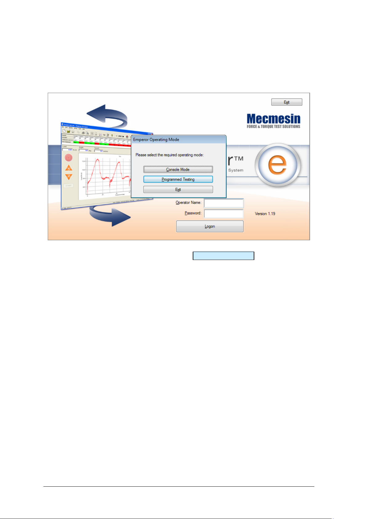
Start the program by using the Emperor icon that was installed on your computer
desktop—the initial login screen is displayed.
Emperor software provides two levels of user, and a password is used to restrict access to
either a simple choice of pre-defined tests or some limited functions, or to give access to
the full configuration and programming capabilities of the Emperor system.
Operators can select from tests that are pre-defined, and for which reports have already
been written, and some functions that can be assigned to each user account.
Masters have full access to all the functions of the Emperor system. The master user has
control over which users are operators and masters.
Logon with a Master level username and password. If this is the first time you have
started the program, you can use:
Assembly and Installation of the Helixa Precision Torque Tester Mecmesin 15
Page 20
Default Username: supervisor
Default Password: supervisor
Note: both the username and password are case-sensitive.
On the Operating Mode selection screen, click on Programmed Testing .
This will start Emperor, and you can set your system preferences, user accounts, create
and run test programs, review results, perform calculations for analysis, produce test
reports and export data for use elsewhere. For full details, see the manual: Emperor Force
and Torque Testing Software, Operator Manual.
16 Mecmesin Assembly and Installation of the Helixa Precision Torque Tester
Page 21
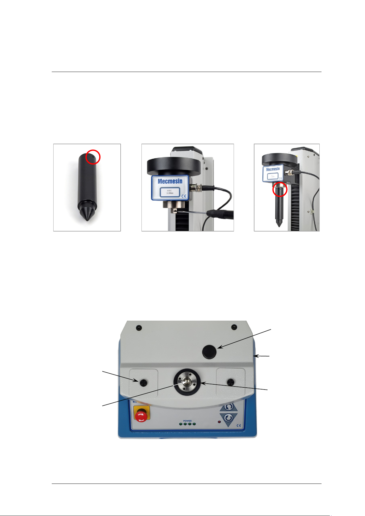
7. Pr ecision Alignment
The vertical alignment between the torque cell and the main spindle can be set accurately
with your torque cell for the most precise measurement.
An alignment tool is attached to the square drive of the HTC. This may require
adjustment of the square drive ball detent, using a small flat-bladed screwdriver to
slightly release the grub screw on the opposite face to the ball (centre, below).
The alignment tool Adjust the square drive ball detent Alignment tool attached
The alignment tool must be positioned with the small holes (circled) aligned with the ball
detent.
7.1 Procedure
Identify these alignment features:
inspection
grommet
Drive spindle bel t
retraction point
adjustment
covers
drive spindle
cover disc and
self-centering m ain
drive spindle
‘O’-ring
The supplied T-bar Allen key is used for making adjustments.
Assembly and Installation of the Helixa Precision Torque Tester Mecmesin 17
Page 22
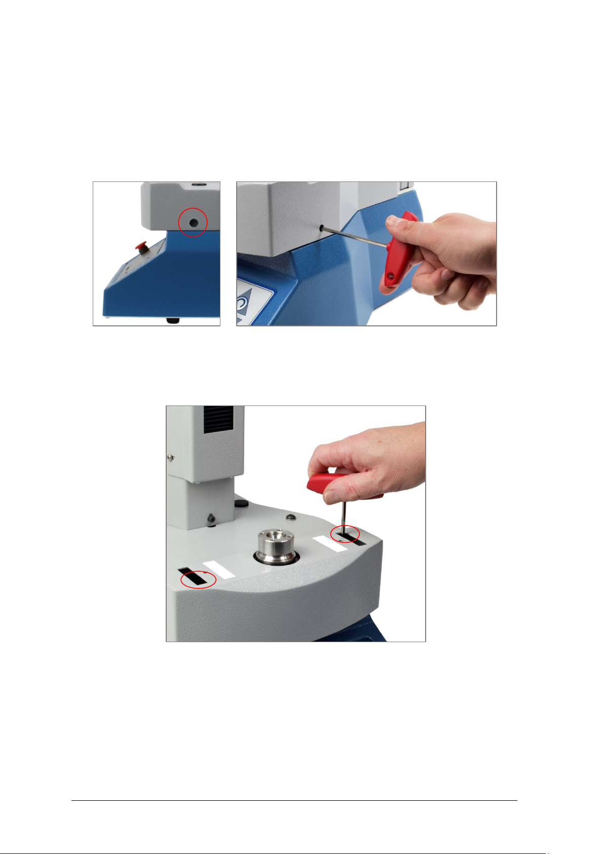
1. Switch the Helixa off at the back.
2. Fit the cone-tipped alignment tool to the torque cell as above.
3. Release the spindle drive belt tension. Pull out the small black grommet from the
right-hand side of the grey deck as shown. This covers the drive spindle belt
retraction point. Insert the T-bar Allen key and locate it in the adjustment bolt head.
Tighten the screw—around 4.5 turns clockwise.
4. Release the two square covers from the cover assembly to expose the adjustment slots.
5. Release the two socket-cap head screws holding the spindle in position (carefully note
positions circled below) and test that the main spindle is free to move.
6. Carefully lower the crosshead until the alignment tool engages fully to self-align the
main drive spindle:
18 Mecmesin Assembly and Installation of the Helixa Precision Torque Tester
Page 23
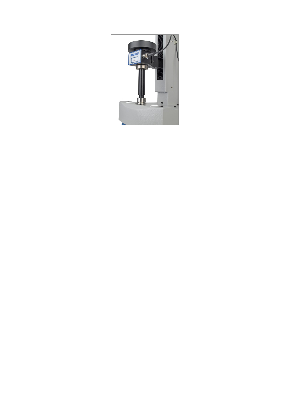
With a light hand pressure on top of the HTC to maintain engagement, secure the
crosshead using its fixing lever on the right side of the main column, and the main
drive spindle will self-align.
7. Check that there is no free movement in the main drive spindle.
8. Carefully retighten the two fixing screws.
9. Release the crosshead fixing lever. Move the crosshead and alignment tool away.
10. Reinsert the T-bar Allen key in the belt retraction point, and turn anti-clockwise to
fully release. The adjustment bolt is captive, so cannot be released too far.
11. Refit the grommet, adjustment covers, cover disc and ‘O’ ring.
12. Push the crosshead and alignment tool carefully into the main spindle once more, to
confirm correct alignment.
13. Move the crosshead to the top and remove the alignment fixture from the HTC.
Assembly and Installation of the Helixa Precision Torque Tester Mecmesin 19
Page 24

Appendix A
System Specifications
Torque transd uce r (HTC) range 0.1 N.m 0.2 N.m 0.3 N.m 1.0 N.m 1.5 N.m 3.0 N.m 6.0 N.m
N.m
kgf.cm
lbf.in
Axial alignment
Total runout (without fixtures) Better than ±0.25 mm
Speed
Speed range 0.1 to 30 rev/min (clockwise or anticlockwise)
Speed accuracy ±0.2% of indicated speed
Speed resolution 0.1 rev/min
Torque measurement (using Emperor™)
Torque accuracy ±0.5% of full scale
Torque resolution Better than 0.01% of full scale
Torque units display mN.m, N.cm, N.m, kgf.cm, gf.cm, ozf.in, lbf.ft, lb f .in
Sampling rate 1 kHz, 500 Hz, 100 Hz, 50 Hz, 10 Hz
Displacement
Maximum displacement
(from tared position)
Turntable pos itional accuracy 0.1º
Software displacement displayed
resolution
System resolution
(software d isplacement/turntable
positional resolution)
Dimensions
Height 758 mm
Width 290 mm (Helixa-i)
Depth 414 mm (without external weight hanger)
Headroom (witho ut fi x tur es ) 350 mm
Throat dep th 127 mm (without bellows)
Weight 28 kg (Helixa-i)
Static weig hts
Rear counterbalance 40 N (maximum)
Torque cell mass platen 60 N (maximum)
0 – 0.1
0 – 1
0 – 0.9
2,500 revs
0.2º
0.045º
587 mm (Helixa-xt)
506 mm (with external weight ha ng er)
111 mm (with bellows )
32 kg (Helixa-xt)
0 – 0.2
0 – 2
0 – 1.8
0 – 0.3
0 – 3
0 – 2.7
0 – 1.0
0 – 10
0 – 8.9
0 – 1.5
0 – 15
0 – 13.3
0 – 3.0
0 – 30
0 – 26.5
0 – 6.0
0 – 60
0 – 53.1
20 Mecmesin Assembly and Installation of the Helixa Precision Torque Tester
Page 25

Communications
Digital I/O 6 input, 6 output (TTL)
Printer/datalogger, and results file
transfer (Heli x a-xt only)
Network communications
(Helixa-xt only)
Power supply
Maximum input power 120 W
Voltage (nomi nal) 230 V AC 50 Hz, or 110 V AC 60 Hz
Operating environment
Recommended temperatur e range +10° to +35° C (50° to 95°F)
Humidity Normal industry and laboratory conditi ons, non-condensing
Noise emissions
Less than 70 db(A)
Mecmesin reserves the right to alter equipment specifications without prior notice.
E&OE
RS232 and USB
Ethernet RJ45
USB for external wireless connect ivity
Assembly and Installation of the Helixa Precision Torque Tester Mecmesin 21
Page 26
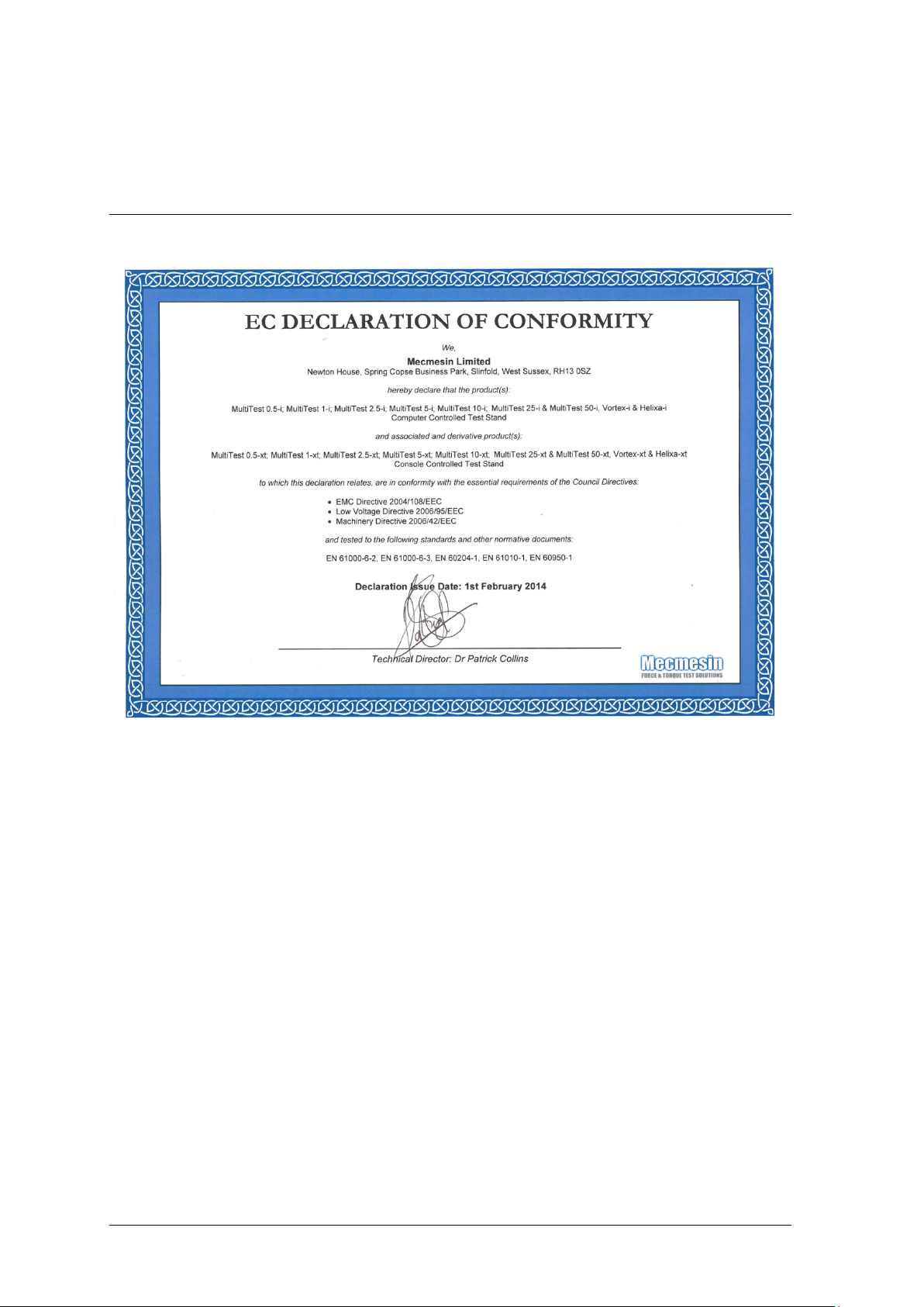
Appendix B
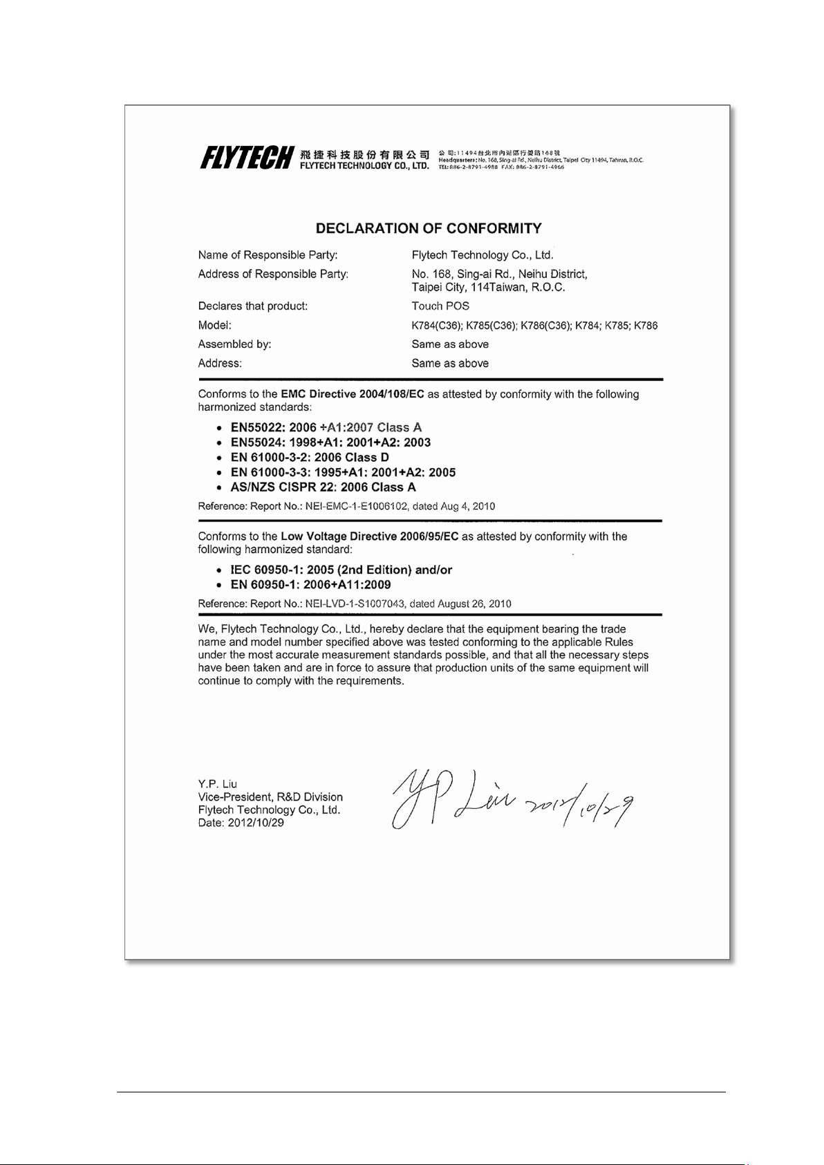
EC Declarations of Conformance
22 Mecmesin Assembly and Installation of the Helixa Precision Torque Tester
Page 27
Assembly and Installation of the Helixa Precision Torque Tester Mecmesin 23
Page 28
Appendix C
Microsoft® Windows® Embedded Standard 7
Licensing
Each Helixa-xt system supplied with a console controller has Microsoft® Windows®
Embedded Standard 7 Operating System pre-installed and licensed by Mecmesin. Each is
supplied with the following as proof of licensing:
• End User Licence Agreement (EULA)
• Certificate of Authentication (COA)
End User Licence Agreement (EULA)
A multi-language EULA is enclosed with each system.
Certificate of Authentication (COA)
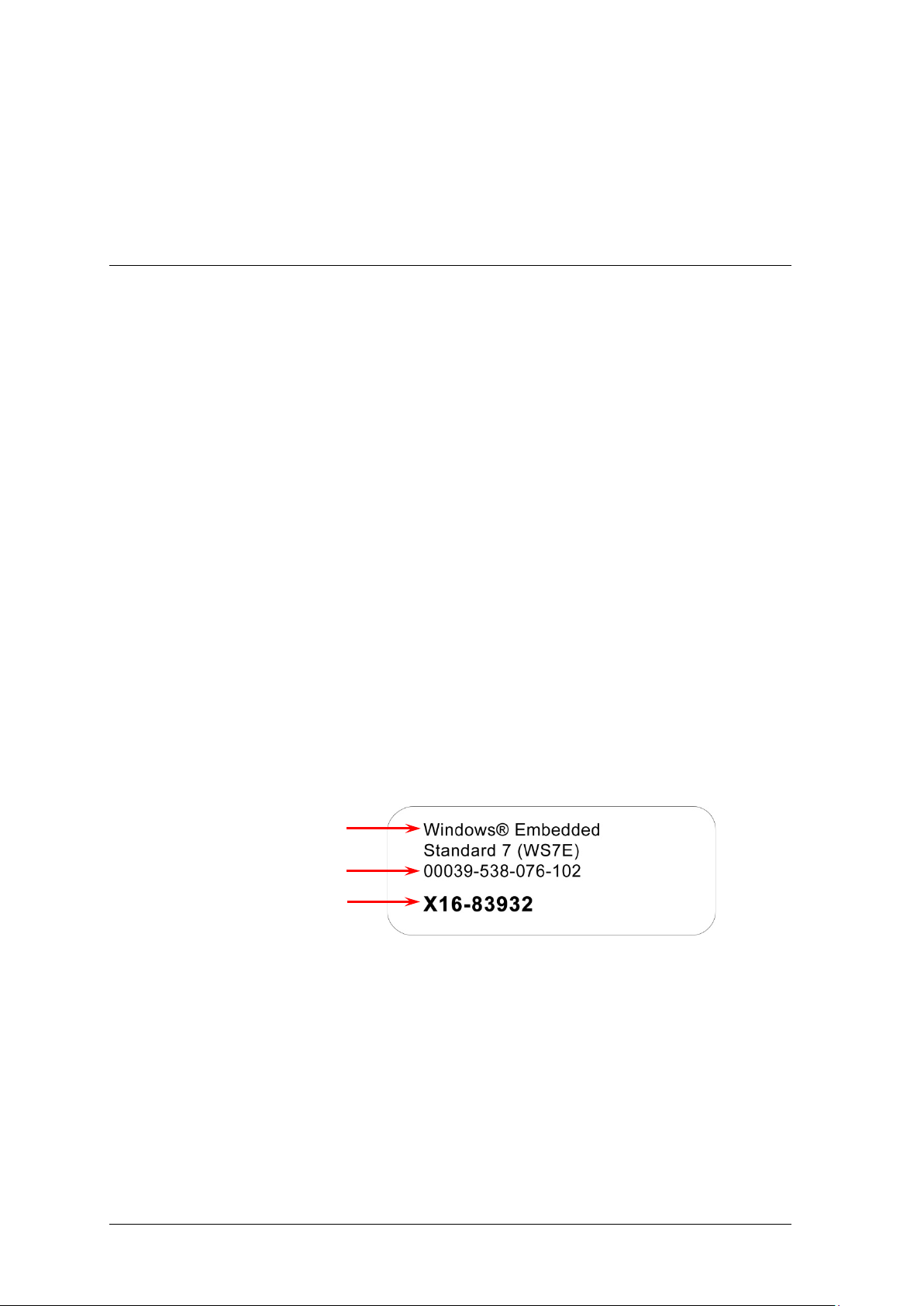
The COA is supplied as a sticker located on the rear of each console supplied with a
system, as proof of licensing.
This COA sticker lists the following:
• Microsoft® product title
• COA serial number
• Microsoft® SKU (stock keeping unit) number
Microsoft® Product Title
COA Serial Number
Microsoft® SKU#
Figure 1: Certif ica te of Authentication
24 Mecmesin Assembly and Installation of the Helixa Precision Torque Tester
Page 29

Page 30

Head Office
France
Germany
North America
Asia
China
Mecmesin : a world leader in affordable force and torque testing solutions
Since 1977, Mecmesin has assisted thousands of companies achieve enhanced quality control in design and production.
The Mecmesin brand represents excellence in accuracy, build, service, and value. In production centres and
research labs worldwide, designers, engineers, operators, and quality managers endorse Mecmesin force and torque
testing systems for their high performance across countless applications.
www.mecmesin.com
Algeria
Argentina
Australia
Austria
Bangladesh
Belgium
Brazil
Bulgaria
Cambodia
Canada
Chile
China
Colombia
Costa Rica
Croatia
Czech Republic
Denmark
Ecuador
Egypt
Estonia
Finland
France
Germany
Greece
Hungary
India
Indonesia
Iran
Ireland
Israel
Italy
Japan
Korea
Laos
Latvia
Lebanon
Lithuania
Malaysia
Mexico
Morocco
Myanmar
Netherlands
New Zealand
Norway
Peru
Philippines
Poland
Portugal
Romania
Russia
Saudi Arabia
Serbia
Singapore
Slovakia
Slovenia
South Africa
Spain
Sri Lanka
Sweden
Switzerland
Taiwan
Thailand
Tunisia
Turkey
UK
USA
Vietnam
The Mecmesin global distribution network guarantees your testing solution is rapidly delivered and
efficiently serviced, wherever you are.
Mecmesin Limited
w: www.mecmesin.com
e: [email protected]
Mecmesin Corporation
w: www.mecmesincorp.com
e: [email protected]
Mecmesin France
w: www.mecmesin.fr
e: [email protected]
Mecmesin Asia Co. Ltd
w: www.mecmesinasia.com
e: [email protected]
Mecmesin GmbH
w: www.mecmesin.de
e: [email protected]
Mecmesin (Shanghai) Pte Ltd
w: www.mecmesin.cn
e: [email protected]
 Loading...