

Page 1
MEA
soil moisture
and
climate monitoring
with
certainty
Get a
Green
Brain
Junior
Weather
Station
User Manual
41 Vine Street
Magill
South Australia 5072
Version 2.0
November 2013
Page 2

Junior Weather Station User Manual
Notices
Copyright
Copyright © Measurement Engineering Australia Pty. Ltd. 2012
All rights reserved. Under the copyright laws, this manual may not be copied, in whole or in part
by any means without the written consent of Measurement Engineering Australia Pty. Ltd.
Design Changes
Measurement Engineering Australia Pty. Ltd. reserves the right to change the designs and
specications of its products at any time and without prior notice.
Contact
Measurement Engineering Australia Pty. Ltd.
41 Vine Street
MAGILL SA 5072
Telephone 08 8332 9044
Fax: 08 8332 9577
Web: www.mea.com.au
Warranty
MEA oers a 12 month, return-to-factory warranty on all new logging systems and hardware.
The warranty applies to hardware, software and system defects only. The warranty does not
cover acts of misuse by the user or third parties, including misuse arising from failure to install
or operate a system or its components in accordance with relevant system documentation, or
failure to seek advice from MEA regarding correct installation or operation of a system or its
components.
Support
If you have questions or problems that cannot be resolved using the information in this manual,
contact MEA technical support using the details above. If phoning, ask for the Operations
Manager and explain the issue. The Operations Manager will assign a Technician to help resolve
the issue. Quoting your MEA Job Reference Number will enable us to quickly locate your details.
Phone support is generally available Monday to Friday between 9am and 5pm Central (ie South
Australian) Standard or Summer Time.
Site visits can be arranged but will incur charges for labour, travel time and where applicable,
accommodation and meals.
MEA technicians can only oer support for issues relating directly to the operation of Magpie
software or MEA logging systems or hardware. For general computer issues please consult a
computer technician.
Page 2www.mea.com.au
Page 3

Junior Weather Station User Manual
Contents
Introduction ............................................................................................6
Contents of the Shipping Crate .............................................................7
The Assembled Weather Station ...........................................................8
Virtual Instruments .......................................................................................................10
Delta T ...................................................................................................................10
Degree Days ..............................................................................................................10
Dew Point ...................................................................................................................10
Chill Units ...................................................................................................................10
Frost Hours ................................................................................................................11
Daylight Hours .........................................................................................................11
EvapoTranspiration .................................................................................................11
Site Preparation ....................................................................................12
Hardware Installation ..........................................................................14
Required Tools and Equipment................................................................................14
Mounting Post ...............................................................................................................15
Bolt the Weather Station to the Post ......................................................................16
Adjust the Solar Panel .................................................................................................17
Level the Solar Radiation Sensor ............................................................................. 18
Solar Radiation Sensor Maintenance ...............................................................19
Air Temperature & Relative Humidity Sensor......................................................20
Air Temperature & Humidity Sensor Maintenance .....................................20
Install the Rain Gauge .................................................................................................21
Rain Gauge Maintenance .....................................................................................23
Soil Temperature Sensor ............................................................................................26
Soil Temperature Sensor Maintenance ...........................................................27
Leaf Wetness Sensor ....................................................................................................28
Page 3www.mea.com.au
Page 4

Junior Weather Station User Manual
Leaf Wetness Sensor Maintenance ...................................................................29
Software Installation and Operation ..................................................30
A Brief Introduction to Magpie ................................................................................30
Install Magpie 3 Software and the Logging Scheme .......................................30
How to Find Magpie Files on Your Computer .....................................................31
Loading the Logging Scheme .................................................................................. 32
Install the System Battery ..........................................................................................32
Connect the Laptop to the Weather station .......................................................33
Open the Logging Scheme .................................................................................34
Set the Connection Method and COM Port...................................................35
Program the Data Logger .....................................................................................36
Real Time Information .................................................................................................36
Logger Information ................................................................................................37
Channel Inputs .........................................................................................................38
Channel Selection Grid .........................................................................................38
Retrieving Measurements ..........................................................................................39
Set the Connection Method ................................................................................39
Unload Data ..............................................................................................................41
View Data .........................................................................................................................42
The Navigator ...........................................................................................................42
Open a New Graph .................................................................................................44
Open a New Table ...................................................................................................45
Favourite Graphs and Tables ...............................................................................46
Test the Packet Data Terminal ..................................................................................47
Force a PDT Transfer ...............................................................................................47
Observe the result ..................................................................................................48
What the Lights Mean ...........................................................................................48
Page 4www.mea.com.au
Page 5

Junior Weather Station User Manual
Testing FTP Unloading in Magpie 3 ..................................................................50
How to Change Parameters for Virtual Instruments ........................................52
Entering Your Altitude for the Delta T Instrument ......................................52
Changing the Threshold Temperature for Frost Hours ..............................53
Entering Latitude and Altitude for the ETo Instrument.............................54
System Maintenance ............................................................................55
Power Supply Maintenance ......................................................................................55
Solar Panel .................................................................................................................55
Battery Validation Errors .......................................................................................55
System Battery .........................................................................................................56
How to Replace the System Battery .................................................................56
How to Replace the System Fuse ......................................................................57
Page 5www.mea.com.au
Page 6

Junior Weather Station User Manual
Introduction
Thank you for purchasing an MEA Junior Weather Station. This manual explains how to
install and operate your weather station. Please read it thoroughly before attempting
to install or operate your weather station.
Please note that your weather station has been ‘built to order’ and the manual
may make reference to climate sensors or other features which are not part of your
particular system.
If you have a question about the installation or operation of your Junior Weather
Station which is not answered in this manual, or if you see something you think is
wrong, please contact MEA using the details inside the front cover of this manual.
Page 6www.mea.com.au
Page 7
Junior Weather Station User Manual
Contents of the Shipping Crate
Your Junior Weather Station has been shipped to you in a large plywood box so that
the weather station is well protected in transit.
The combined weight of the weather station and the shipping crate is
approximately 60 kg. Use mechanical lifting aids or team lifting when moving the
shipping crate.
The crate contains:
● A data recorder and data transfer devices in a square plastic enclosure, bolted to
an upright.
● A cross arm with a solar panel and solar radiation sensor attached.
● An LP02 global solar radiation sensor.
● A PA2 wind speed sensor and a PRV wind direction sensor.
● A HC2-S3 air temperature and relative humidity sensor.
● An MEA2040 leaf wetness sensor.
● A 6507A soil temperature sensor.
● A universal mounting bracket and U-bolt assemblies.
● A disk or USB drive containing software and documentation.
● A USB cable.
Page 7www.mea.com.au
Page 8
Junior Weather Station User Manual
The Assembled Weather Station
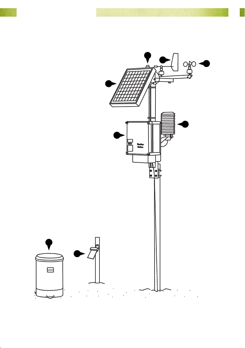
Following assembly your weather station will look like this.
2
1
6
3
5
4
7
8
Fig. 1. Junior Weather Station.
Page 8www.mea.com.au
Page 9
Junior Weather Station User Manual
1
Solar panel. The solar panel keeps the system battery charged and powers the data
logger and all of the instruments on your weather station.
2
Solar radiation sensor. This sensor measures direct and diuse (global) solar
radiation in a 180° eld of view. Solar radiation measurements can be used in the
calculation of Daylight Hours and potential Evapotranspiration.
3
Wind direction sensor. Wind direction can be an important thing to know for spray
applications.
4
Wind speed sensor. Wind speed is also an important thing to know for spray
applications. Wind speed measurements can also be used in the calculation of potential
Evapotranspiration.
5
Air temperature and relative humidity sensor shelter. Air temperature and relative
humidity can be used in the calculation of potential Evapotranspiration, Delta-T,
Apparent Temperature, and Dew Point. Air temperature can also be used in the
calculation of Frost Hours, Degree Days and Chill Days.
6
The logger enclosure. This contains the data logger, system battery and, if ordered,
the devices that will transfer your weather recordings to the Internet.
7
The rain gauge. A two-compartment bucket inside the gauge collects rainfall as it
passes through the gauge. As each compartment becomes full, the bucket ‘tips’ around
a pivot, then the other compartment begins to ll. Each ‘tip’ corresponds to 0.2 mm of
rainfall.
8
Leaf wetness sensor. The sensor acts like an articial leaf and detects the presence
of moisture on its surface. Rather than simply ‘wet’ or ‘dry’, the sensor can measure
surface moisture over the entire range from 0 to 100%.
9
Soil temperature sensor (not shown).
Page 9www.mea.com.au
Page 10

Junior Weather Station User Manual
Virtual Instruments
The inputs from the climate sensors on your Junior Weather Station are combined in
Magpie software to calculate additional values, called ‘virtual’ instruments.
Delta T
Delta T is one of the standard indicators for acceptable spray conditions. It is indicative
of evaporation rate and droplet lifetime. Delta T is calculated by subtracting the wet
bulb temperature from the dry bulb temperature. The result is expressed as °C.
When applying pesticides, Delta T should ideally be between 2 and 8°C (Source: http://
reg.bom.gov.au/info/leaets/Pesticide-Spraying.pdf).
Your Junior Weather Station calculates Delta T from air temperature, relative humidity
and the altitude of the site where the station is located.
You will need to enter the altitude into the logging scheme so that Delta T can be
correctly calculated. Please see “Entering Your Altitude for the Delta T Instrument” on
page 52 for further details.
Degree Days
Degree days are a measure of heat accumulation used to predict plant maturation
rates. It is calculated from air temperature. By default, the calculation assumes that
no growth will occur below 10°C or above 35°C. The result is expressed in °C, and is
updated at 9 am each day.
Dew Point
Dew point is the temperature to which the air would have to be cooled to in order
for condensation of water vapour to occur. It is calculated from air temperature and
relative humidity. The result is expressed in °C.
Chill Units
Vegetative and fruiting buds for some types of crop remain dormant until they have
accumulated sucient ‘chill units’. The ‘Utah Method’ is used to assign chill units with a
positive value between 1.4 and 12.4°C, zero units from 12.5 to 15.9°C and negative units
above 16°C.
Chill units are updated at 9 am each day.
Page 10www.mea.com.au
Page 11

Junior Weather Station User Manual
Frost Hours
Frost hours is the accumulation of time below a threshold air temperature of 2°C. The
calculation is an indication of the conditions under which frost is likely to occur, not an
actual measurement of frost conditions. The result is expressed in hours and is updated
at 9 am each day.
The threshold value can be adjusted to suit local conditions if required. Please see
“Changing the Threshold Temperature for Frost Hours” on page 53 for further details.
Daylight Hours
Daylight hours is the accumulation of time spent above a threshold global solar
radiation measurement of 10 W/m2. The result is expressed in hours and is updated at
9 am each day.
EvapoTranspiration
Evapotranspiration is the combined loss of water from a soil surface (evaporation)
and from the stomatal pores of plants (transpiration). Magpie uses the FAO PenmanMonteith model to calculate potential ETo. ETo is calculated from air temperature,
relative humidity, solar radiation, wind speed, daylight hours, latitude and altitude. The
result is expressed in mm and is updated at 9 am each day.
You will need to enter the latitude and altitude for the weather station site in the
logging scheme so that ETo can be correctly calculated. Please see “Entering Latitude
and Altitude for the ETo Instrument” on page 54 for further details.
Page 11www.mea.com.au
Page 12

Junior Weather Station User Manual
Site Preparation
Before installing the weather station, select and prepare a suitable site.
The site selected should be representative of the average conditions over the area of
interest.
If the site is not staed, then the weather station should be located in a secure area or
out-of-sight. Any protective fencing should not shade the solar panel or solar radiation
sensor.
The following requirements should be considered:
● The ground should not be either too hard or too soft to prevent inexpensive
installation of the weather station or any necessary protective fencing.
● If your weather station delivers data to the Internet, the site should have good
mobile phone reception.
● The site should be easy to get to for maintenance and inspection of the station.
● The general area should be level.
● The area should not be articially watered.
● Any vegetation surrounding the weather station will need to be cropped to a
height of a few cm as part of routine maintenance.
● The use of compacted ‘hard standings’ is not recommended as this can give
unrepresentative soil and air temperature results.
● A separate area approximately 4 m from the weather station should be prepared
for the rain gauge.
The distance of any obstruction (eg fences, trees, buildings) less than 15 m tall should
be at least four times the height of the tallest obstruction away from the weather
station.
For obstructions taller than 15 m the distance to the weather station will need to be
increased up to ten times the height of the obstruction if the angle from the top of
the weather station to the top of the obstruction is more than 45°. Isolated thin masts
closer to the enclosure are acceptable if they don’t cast a shadow on the solar radiation
sensor or solar panel and are located down-wind of the prevailing winds.
Page 12www.mea.com.au
Page 13

Junior Weather Station User Manual
Sites chosen should not be:
● Subject to ooding or inundation by storm surge.
● Aected by a high water table.
● Prone to subsidence.
● Unduly susceptible to lightning strike.
● Vulnerable to bushre.
Page 13www.mea.com.au
Page 14

Junior Weather Station User Manual
Hardware Installation
Required Tools and Equipment
To install the weather station and rain gauge you will need:
● A galvanised steel post with an outside diameter of 40~50 mm, 1.5 m long.
● Rapid-set concrete if the post is to be concreted in.
● 13 mm AF spanner.
● 10 mm AF spanner.
● Medium Phillips No. 2 screwdriver.
● 5 mm AF hexagonal key.
● 4 mm AF hexagonal key (supplied).
● Shovel or 40 mm Auger.
● Post level.
● Sledgehammer.
● Compass.
● Stepladder.
● Laptop with Magpie 3 software and the logging scheme installed (software
supplied).
● USB Type-A male to Type-B male cable (supplied).
Page 14www.mea.com.au
Page 15
Junior Weather Station User Manual
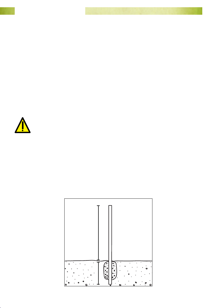
Mounting Post
The weather station is designed to be mounted to a galvanised steel tube with an
outside diameter of 40~50 mm. The post needs to be positioned in a place where the
sun can shine on the solar panel for most of the daylight hours and tall enough to
ensure that the panel can ‘see over’ any obstacles.
Galvanised Post: Concrete Method
1. Dig a hole about 150 mm in diameter and 400 mm deep.
2. Drive the pole into the bottom of the hole an extra 100 mm so that it stands
vertically and 1 m remains above the surface. Use the post level to ensure that
the post is vertical.
3. Backll the hole with quick setting concrete according to the instructions on the
bag.
Concrete dust can be hazardous to your health. Follow all safety directions
printed on the concrete bag.
4. Let the concrete set before tting anything to the post. Check the post and ensure
that it is rmly supported in the ground.
Galvanised Post: No Concrete Method
1. If the soil conditions allow it, auger a 40 mm hole 300 ~ 400 mm deep and drive
the post directly into the soil so that 1 m remains above the surface.
2. Check the post and ensure that it is rmly supported in the ground and is vertical.
Ø 40~50 mm
1 m
0.5 m
Page 15www.mea.com.au
Page 16
Junior Weather Station User Manual
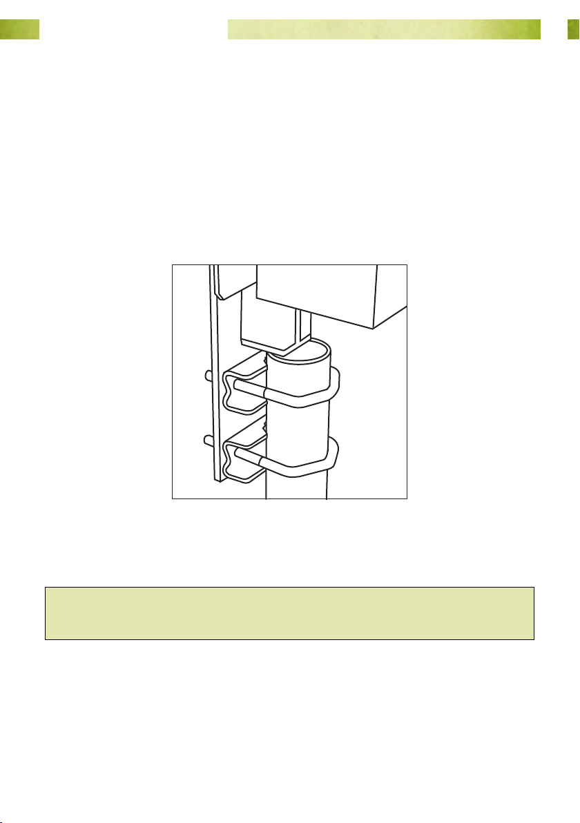
Bolt the Weather Station to the Post
Mount the weather station to the post as per the diagram below.
1. Loosely t 2 U-bolts and clamp saddles to the front of the mounting bracket
below the logger enclosure (if using a square post the clamp saddles can be left
out).
2. Slide the U-bolts over the top of the post until the spine of the weather station
rests on top of the post, as indicated in Fig. 2.
3. Make sure the solar panel faces north then tighten the nuts on the U-bolts using a
13 mm AF spanner.
Fig. 2. Bolt the weather station to the
top of the post as shown.
Hint: This will be easier with two people so that one person can hold the weather
station while the other tightens the nuts.
Page 16www.mea.com.au
Page 17
Junior Weather Station User Manual
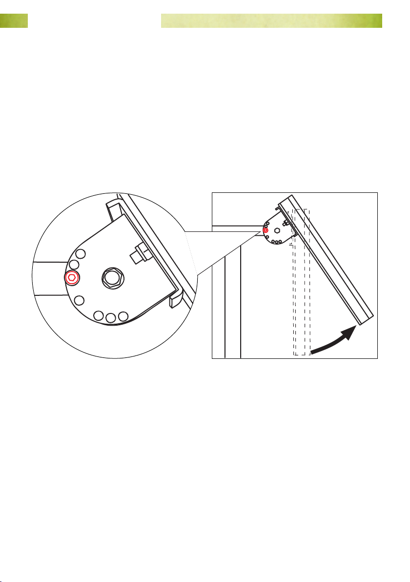
Adjust the Solar Panel
The solar panel should face north and be adjusted at an angle suitable for the latitude
of the station.
1. Use a compass to north-align the solar panel.
2. Use a 5 mm AF Hex key to remove the 2 tilt adjustment screws.
3. Swing the solar panel up until it is at your latitude +15° from horizontal (45°
works well enough throughout most of Australia). The tilt adjustment bracket has
7 positions, pick the one closest to your desired tilt.
4. Re-insert the tilt adjustment screws and tighten.
Fig. 3. Remove the tilt-adjustment screws (illustrated in red) on both sides of the tilt
adjustment bracket, move the solar panel to your desired angle and replace the
screws.
Page 17www.mea.com.au
Page 18
Junior Weather Station User Manual
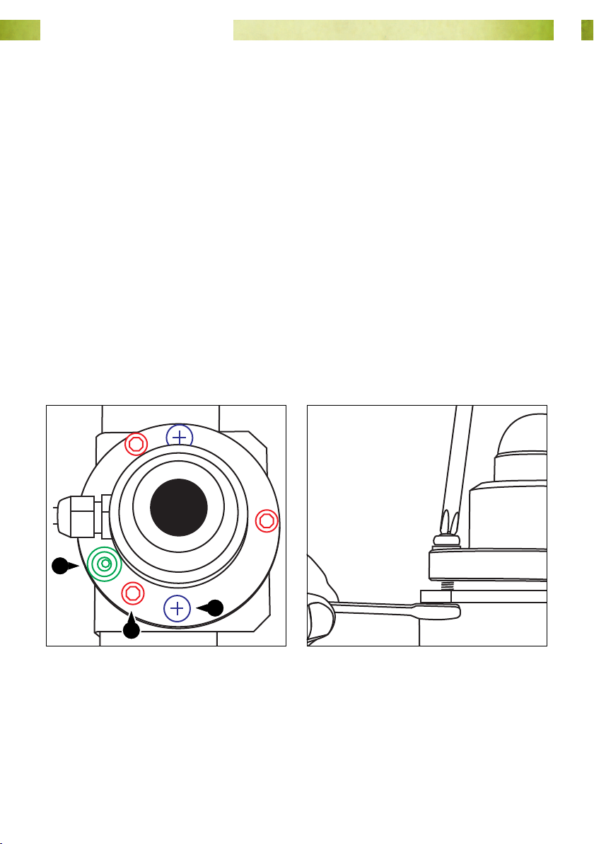
Level the Solar Radiation Sensor
The solar radiation sensor is shipped pre-mounted to its mounting bracket on the cross
arm to the rear of the solar panel, but will require levelling on site.
1. Remove the packing materials covering the glass dome of the sensor.
2. Position the stepladder so that you can see the built-in bullseye level on the solar
radiation sensor.
3. If the bubble is centred inside the black ring on the level then no further
adjustment is required.
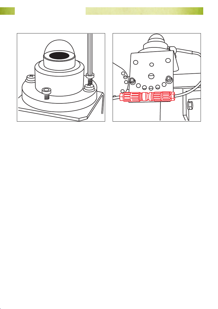
4. If levelling adjustment is required, use a medium Phillips No. 2 screwdriver and
a 8 mm AF spanner to loosen the mounting screws.
5. Use a 4 mm AF Hex key to adjust the 3 levelling screws until the bubble is centred
inside the black ring on the bullseye level.
6. Tighten the mounting screws evenly.
7. Check to ensure that the in-line connectors on the solar radiation sensor cable are
connected.
1
3
2
Fig. 4. Levelling the radiation sensor:
1. Bullseye level; 2. Levelling
screw; 3. Mounting screw.
Fig. 5. Loosen the mounting screws.
Page 18www.mea.com.au
Page 19
Junior Weather Station User Manual
Fig. 6. Adjust the levelling screws. Fig. 7. Check the in-line connectors.
Solar Radiation Sensor Maintenance
1. If the solar radiation sensor dome is dirty, wipe it with a cloth dampened with
clean water.
2. The sensor dome is sealed and fully weatherproof. If the dome is damaged or if
condensation appears in the dome, please contact MEA.
3. The manufacturer recommends that the sensor calibration be checked every two
years. This requires removal of the sensor and return to MEA.
Page 19www.mea.com.au
Page 20
Junior Weather Station User Manual
Air Temperature & Relative Humidity Sensor
The sensor is housed in the louvred shelter behind the logger enclosure. It requires no
user installation.
Air Temperature & Humidity Sensor Maintenance
The manufacturer recommends that the calibration of the sensor be checked on an
annual basis. This involves a two-point calibration with the sensor head tted to a
humidity chamber containing reference salt solutions. Return the sensor head to MEA
for calibration. To remove the sensor:
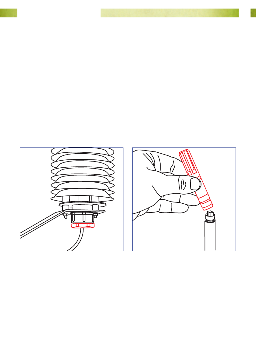
1. Undo the plastic nut on the underside of the shelter. When the sensor is loose,
pull it downward until it is clear of the shelter. Do not pull hard on the cable.
2. Unscrew the locking collar on the sensor head and pull the head clear of the
sensor body. Package the sensor head carefully and send it to MEA.
Fig. 8. Undo the plastic nut to release
the sensor.
3. Return the sensor body to the shelter to protect the exposed connector.
4. The shelter itself should be inspected for cleanliness. Remove spiders and webs
using a soft brush. Clean the shelter using a cloth dampened with clean water.
Fig. 9. Remove the sensor head for
calibration.
Page 20www.mea.com.au
Page 21

Junior Weather Station User Manual
Install the Rain Gauge
The rain gauge is a tipping-bucket gauge with a resolution of 0.2 mm per tip.
This gauge should be located in a cleared area approximately 4 ~ 8 m from the weather
station to minimise any eect the system might have on the operation of the gauge.
The gauge should be bolted to a concrete paver or similar using 6 mm expanding
masonry bolts (not supplied).
The rain gauge cable should either be trenched in or passed through an appropriate
length of plastic conduit. The conduit will need to have an internal diameter of at least
20 mm to allow the rain gauge cable to be passed through it.
The following method describes the installation of a gauge mounted to a paver and
using plastic conduit to protect the cable.
1. Unroll the rain gauge cable and place the gauge at your intended site. Make sure
there will be enough ‘slack’ in the cable to allow it to hang straight down from the
underside of the logger enclosure.
2. Dig a trench approximately 100 mm deep from the base of the enclosure
mounting post to the site where you will install the gauge.
3. Place a paver at the end of the trench. Mark the paver using the holes in the
mounting ange in the base of the gauge as a template, then drill the mounting
holes in the paver and bolt the gauge to it.
4. The collector is held to the base of the rain gauge with 3 Allen head screws.
Loosen the screws using a 4 mm AF Hex key and remove the collector.
5. Level the gauge by reference to the bullseye level in the gauge base.
6. Remove any packing or rubber bands that have been used to prevent the buckets
tipping while in transit, then re-t the collector.
7. Lay out enough conduit to reach the base of the enclosure mounting post and
then push the rain gauge cable through it.
8. Run the cable through a 90° elbow, then a short length of straight conduit so that
the cable will emerge just below the enclosure.
Page 21www.mea.com.au
Page 22
Junior Weather Station User Manual
4 ~ 8 m
1
4
2
3
6
5
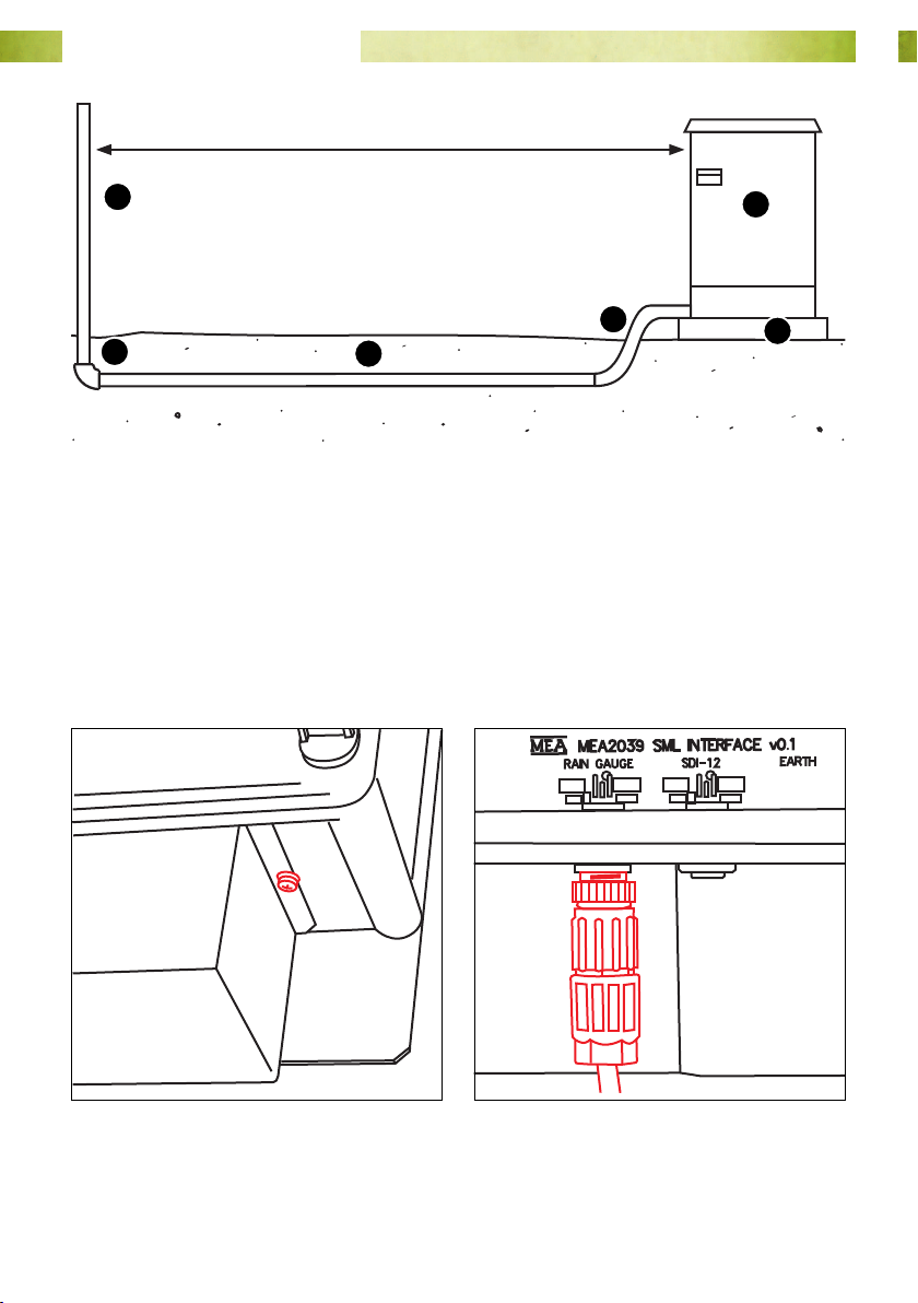
Fig. 10. Conduit sections for the rain gauge cable: 1. Upright section; 2. Elbow; 3. Long
section; 4. Flexible conduit; 5. Paver; 6. Rain gauge.
9. Remove the cable cover on the bottom side of the enclosure. Loosen the
mounting screws with a medium Phillips head screwdriver. Squeeze the sides of
the cover to free it from the screws.
10. Plug the connector on the rain gauge cable into the socket labelled “RAIN GAUGE”
on the underside of the logger enclosure. The correct socket is also marked on the
board inside the enclosure. Replace the cable cover.
Fig. 11. Loosen the screws to remove the
cable cover.
Fig. 12. Connect the rain gauge cable to
the logger enclosure.
Page 22www.mea.com.au
Page 23
Junior Weather Station User Manual
Rain Gauge Maintenance
Routine maintenance should include cleaning the accumulated dirt and debris from
the collector funnel and buckets, as well as ensuring that the gauge is level.
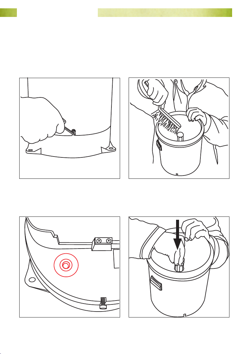
1. Remove the collector using a 4 mm AF Hex key to loosen the screws in the gauge
base. Remove any grasses, dirt etc from the collector with a soft brush.
Fig. 13. Remove the collector. Fig. 14. Clean the collector.
2. Check the bullseye level in the base and adjust the gauge footing if required. Push
the lter and siphon out of the collector.
Fig. 15. Check the level. Fig. 16. Push the lter downward.
Page 23www.mea.com.au
Page 24
Junior Weather Station User Manual
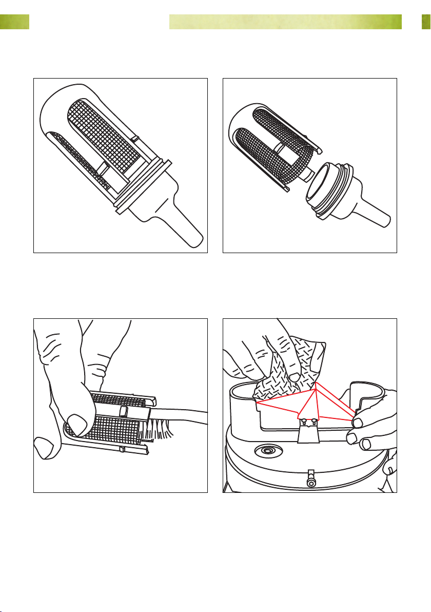
3. Separate the lter and siphon. The lter can be cleaned using a small brush e.g.
toothbrush. Use a pipe-cleaner to clean the siphon nozzle if required.
Fig. 17. The lter / siphon assembly. Fig. 18. Separate the lter and siphon.
4. Clean the inside of the buckets with a clean soft cloth dampened with mild soapy
water. Do not touch the inside surface of the buckets with your ngers.
Fig. 19. Clean the lter and the siphon. Fig. 20. Clean the bucket with a soft cloth.
5. Rinse all parts and buckets (don’t wet the wiring terminal block) with clean water
and reassemble.
Page 24www.mea.com.au
Page 25
Junior Weather Station User Manual
6. Vegetation surrounding the gauge should be clipped level with the top of the
gauge to minimise wind deformation of rainfall and to prevent material falling
into the collector.
The gauge calibration should be checked annually.
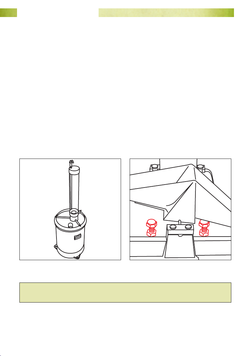
1. Pass exactly 653 ml of water through the gauge at a slow and steady rate and
count the number of times the bucket tips.
2. Repeat the procedure 3 times to obtain an average. A correctly calibrated gauge
should tip 101 times ± 3 tips (ie between 98 and 104 tips on average).
3. If required, calibration adjustment is made by altering the height of the stoppers
beneath the tipping buckets. A pair of 8 mm AF spanners is required.
• Raise both stoppers an equal amount to increase the number of tips.
• Lower both stoppers an equal amount to decrease the number of tips.
• Alter the height of the stoppers 1/4 ~ 1/2 a turn each time before re-
checking the calibration.
Fig. 21. Pass 653 ml of water through the
gauge.
Fig. 22. Adjust the stoppers beneath the
bucket if required.
Hint: If you do not want your weather station to record spurious rainfall,
disconnect the cable from the weather station before commencing calibration.
MEA can supply calibration kits including a calibrated reservoir with self-regulating
ow rate, stand and counter module.
Page 25www.mea.com.au
Page 26
Junior Weather Station User Manual
Soil Temperature Sensor
The soil temperature sensor is a bead thermistor housed in a rugged stainless steel
case.
The sensor will need to be buried at a soil depth which represents your zone of interest.
‘Standard’ depths for soil temperature measurements are 5, 10, 20, 50 and 100 cm.
The site for soil temperature measurements should be a level plot of bare ground
2
(about 75 cm
) and typical of the surrounding soil for which information is required.
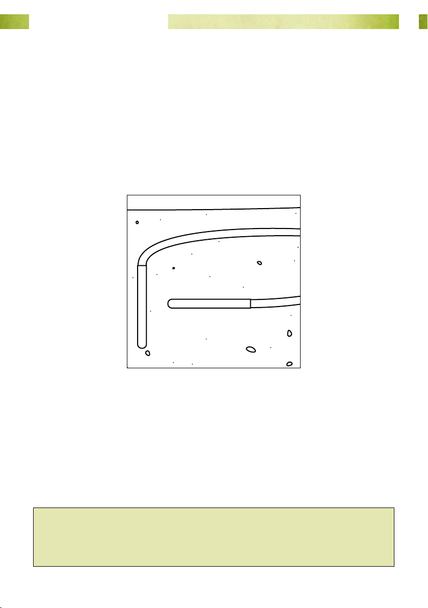
The sensor can be installed horizontally or vertically.
Fig. 23. The soil temperature sensor
can be installed vertically or
horizontally.
The sensor typically comes with 20 m of cable to provide installation exibility. The
sensor cable should be trenched in and/or protected with conduit in order to protect it
from damage by machinery or animals.
The sensor can be run through the same conduit / laid in the same trench as the rain
gauge cable if convenient.
Hint: If the rain gauge cable trench is used, do not bury the soil temperature
sensor under the rain gauge. Excavate a ‘branch’ trench and install the soil
temperature sensor at least 0.5 m from the rain gauge so that the sensor is not
subject to inundation from runo from the rain gauge.
Page 26www.mea.com.au
Page 27

Junior Weather Station User Manual
Soil Temperature Sensor Maintenance
The soil temperature sensor is calibrated for life and contains no serviceable parts.
If you suspect that your soil temperature sensor is faulty, please contact MEA.
Page 27www.mea.com.au
Page 28
Junior Weather Station User Manual
Leaf Wetness Sensor
The MEA2040 Leaf Wetness Sensor acts like an articial leaf and detects the presence of
moisture on its surface. Rather than simply ‘wet’ or ‘dry’, the sensor can measure surface
moisture over the entire range from 0 to 100%.
● The sensor should be installed ‘circuit side up’’.
● The sensor should be installed in a position and at an angle which enables it to
best represent a leaf in the canopy of the crop of interest.
● The sensor should be installed at an angle under the foliage where it will be one
of the last things to get wet, and such that water does not ‘pool’ on the surface.
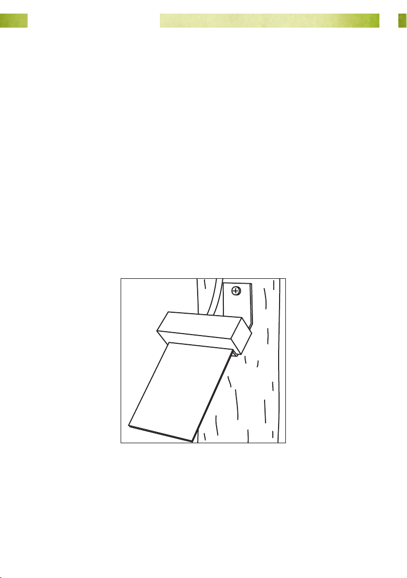
● The sensor is tted with a 45° angle bracket which enables it to be mounted to
a post or wooden stake. Note that the screw holding the bracket can be undone
and the bracket inverted if required. Choose a stake or post which allows the
sensor to be located at the desired canopy height. If necessary a metal extension
can be tted to the bracket.
● Once installed, use a cable tie to support the cable to reduce any strain imposed
on it or the sensor.
Fig. 24. A leaf wetness sensor screwed to
a wooden post.
Page 28www.mea.com.au
Page 29

Junior Weather Station User Manual
Leaf Wetness Sensor Maintenance
The sensor contains no serviceable parts. Its factory calibration will last the life of the
sensor.
1. Periodically inspect the surface of the sensor for deterioration in the printed
circuit.
2. Remove any dust or other materials using a cloth dampened with clean water. Do
not use abrasives to clean the sensor.
3. Avoid touching the surface of the sensor with your ngers as the deposition of
fats or grease will change the surface-tension of the sensor, potentially causing it
to retain water for articially long periods.
4. If the sensor cable crosses a road or track it should be protected in conduit and
trenched in. Periodically inspect the sensor cable for damage.
Page 29www.mea.com.au
Page 30
Junior Weather Station User Manual
Software Installation and Operation
A Brief Introduction to Magpie
For more detailed information on Magpie please refer to the
Magpie 3 User Manual, which can be found on the MEA USB
drive.
In MEA systems data recording is referred to as logging. Log
actions are grouped together in memory locations called
buers.
The data logger behaviour is specied by a program referred to as a logging scheme.
Magpie is used to write schemes, and load them into the data logger.
The logging scheme is also used to view recorded and real time data on a PC using
MEA’s Magpie software.
Install Magpie 3 Software and the Logging Scheme
Install Magpie 3 and the logging scheme from the supplied USB drive:
1. Plug the drive into your computer and navigate to it.
2. Locate the le install.exe and double left-click on it to run it. Any software
located in the Installers folder will be installed to your computer in the locations
listed below.
Page 30www.mea.com.au
Page 31

Junior Weather Station User Manual
How to Find Magpie Files on Your Computer
By default, Magpie 3 will install to:
C:\Program Files\Magpie 3 (for 32-bit Windows operating systems)
or
C:\Program Files (x86)\Magpie 3,(for 64-bit Windows operating systems).
The scheme and subsequent data les will be installed at either of the following
locations:
Windows XP and 2000
C:\Documents and Settings\All Users\Documents\MEA\Magpie\Schemes
In Explorer Documents will be displayed as Shared Documents.
Windows Vista and Windows 7
C:\Users\Public\Documents\MEA\Magpie\Schemes
In Explorer Documents will be displayed as Public Documents.
Page 31www.mea.com.au
Page 32
Junior Weather Station User Manual
Loading the Logging Scheme
To load the logging scheme into the data logger you will need:
● A laptop computer with Magpie software and the logging program (referred to as
a “scheme”) installed.
● A USB type A to type B cable (supplied).
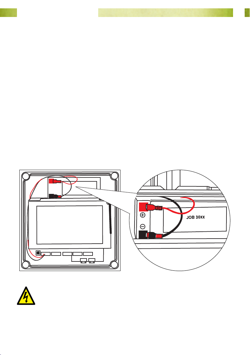
Install the System Battery
The system battery is a 12 V 7 Ah sealed lead acid battery. Locate the battery and
remove any packing materials.
1. Remove the lid of the logger enclosure.
2. Remove the clear terminal protectors from the terminal tabs on the battery .
3. Place the battery on the battery shelf as shown, with the negative (-) terminal
closest to the battery shelf.
4. Connect the battery cable as shown. The receptacles on the battery cable simply
slide over the terminal tabs on the battery.
Fig. 25. Place the battery on the shelf.
Connect the red lead on the battery cable to the positive (+) terminal.
Connect the black lead to the negative (-) terminal.
Fig. 26. Connect the battery as shown.
Page 32www.mea.com.au
Page 33
Junior Weather Station User Manual
Connect the Laptop to the Weather station
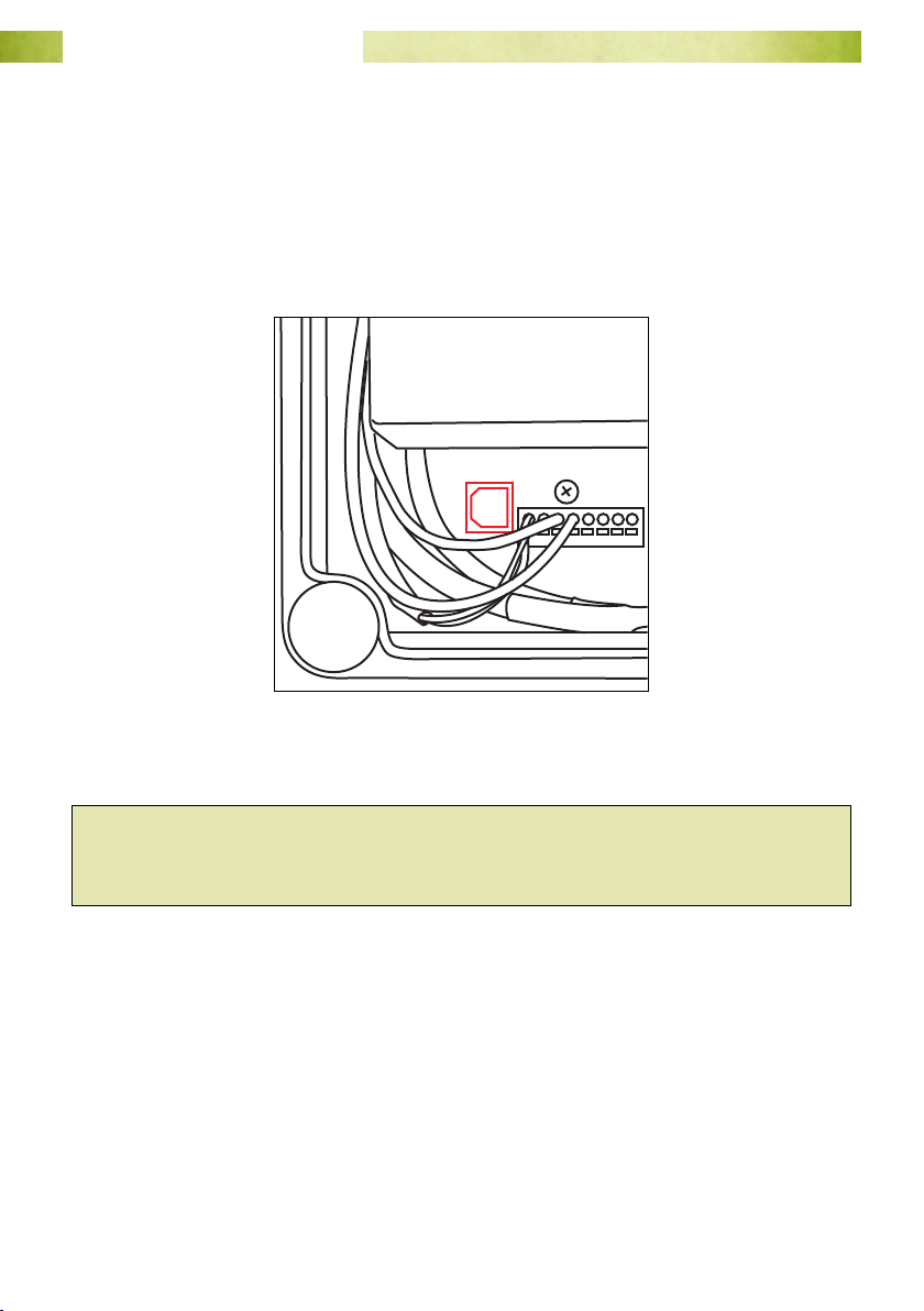
1. Remove the lid of the logger enclosure.
2. Start your laptop. Plug the B-type connector into the COM port shown below, and
the other end into your laptop.
3. Windows will install a generic USB driver. Navigate to the Device Manager to nd
out which COM port has been assigned to the cable.
Fig. 27. The data logger’s COM port.
Hint: If you have a weather station with no telemetry devices, there will already be
a USB extension cable plugged into the USB port on the logger. This will give you
access to the port without having to remove the enclosure lid.
4. Start Magpie software and open the logging scheme.
Page 33www.mea.com.au
Page 34
Junior Weather Station User Manual
Open the Logging Scheme
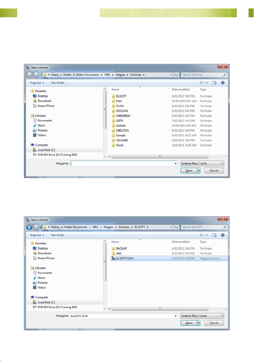
1. From the File menu select Open Scheme.
2. The Open a scheme window will open.
3. Select a scheme folder and double-click to open it.
4. Select the scheme le and double-click the icon, or select Open.
Page 34www.mea.com.au
Page 35
Junior Weather Station User Manual
Set the Connection Method and COM Port
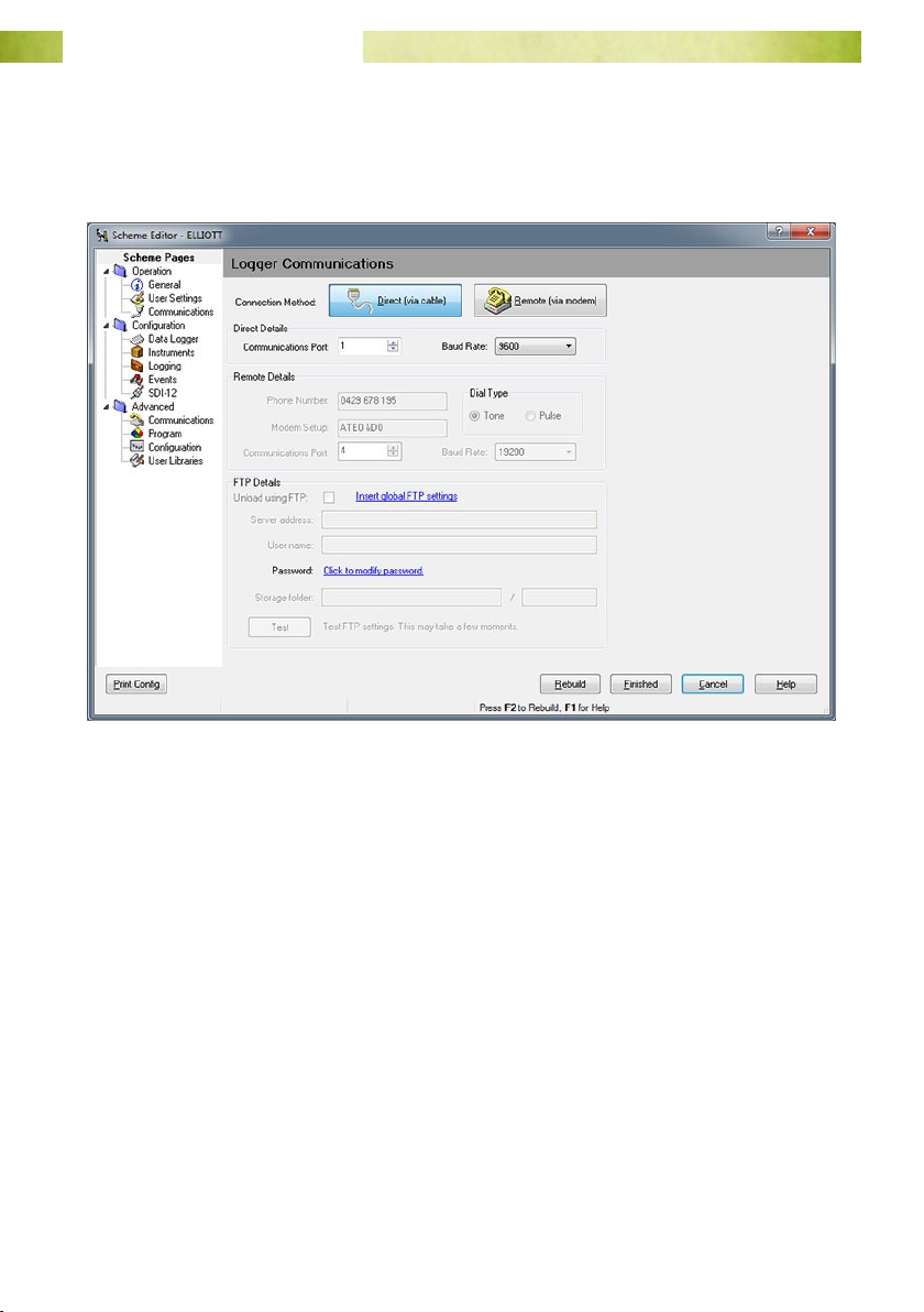
1. From the menu bar select Logger ⇒ Edit Scheme.
2. Go to Operation ⇒ Communications.
3. Set the Communications Method to Direct (via cable).
4. Select the Communications Port your serial cable is attached to.
5. Leave the Baud Rate at 9600.
6. Select Finish to save your changes and close the scheme editor.
Page 35www.mea.com.au
Page 36
Junior Weather Station User Manual
Program the Data Logger
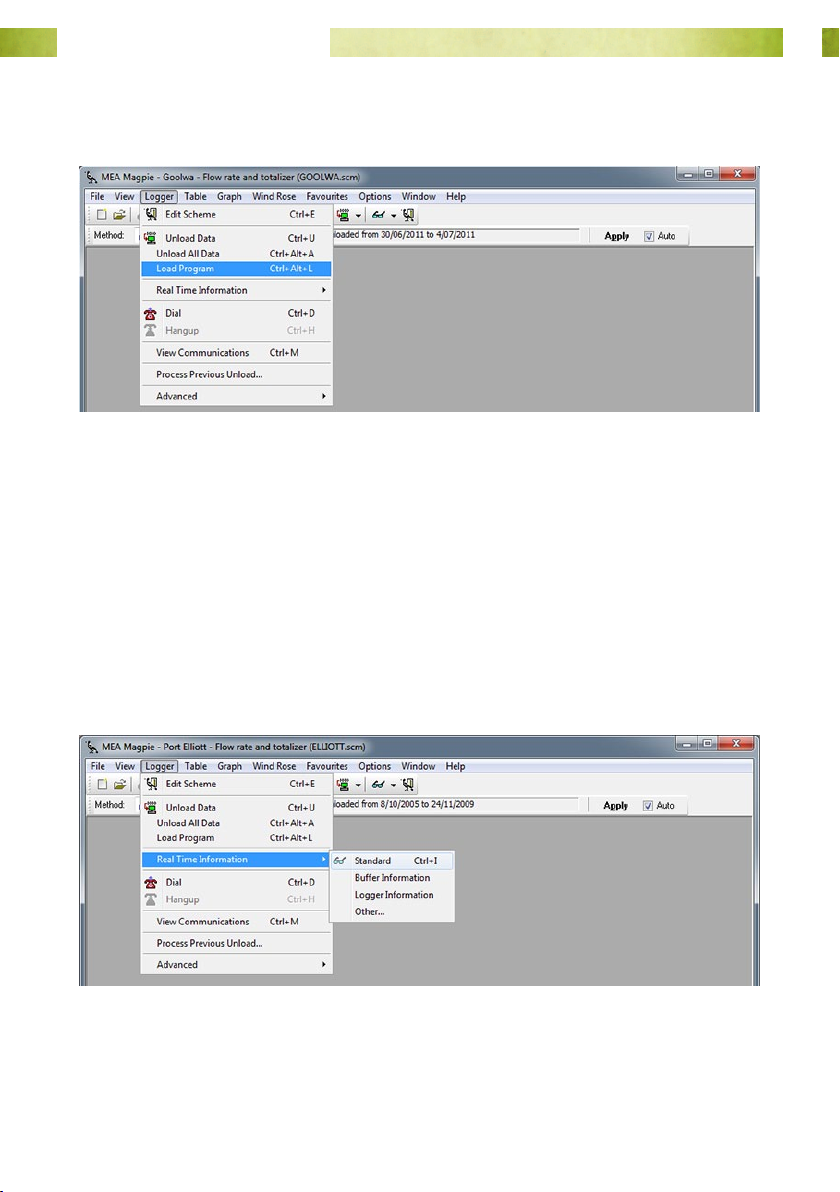
1. From the menu bar select Logger ⇒ Load Program
2. Once the load process is complete, use the Standard RTI screen to check that the
logger has gone from a ‘Primed’ to a ‘Logging’ state, has the correct date & time,
and that the channel inputs are showing expected values.
Real Time Information
Once the scheme has been loaded into the data logger you can see sensor inputs by
viewing the Standard Real Time Information screen.
To open the Standard RTI screen:
From the menu bar select Logger ⇒ Real Time Information ⇒ Standard
Page 36www.mea.com.au
Page 37
Junior Weather Station User Manual
1
2
3
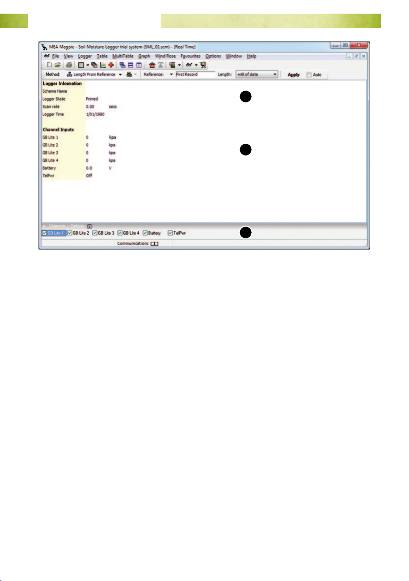
Fig. 28. Standard RTI screen: 1. Logger information; 2. Channel Inputs; 3. Channel
selection grid.
Logger Information
Scheme Name
Check that this is the correct scheme before unloading.
Logger State
Can be ‘Primed’, ‘Logging’ or ‘Stopped’. Data will only be recorded when the data logger
is in a ‘Logging’ state.
Scan Rate
The rate at which the logger is programmed to sample the sensor inputs.
Logger Time
Check to see if the logger date / time is correct. The logger takes its time from the
computer which is used to load it. It does not automatically update changes between
Standard and Daylight Savings times.
Page 37www.mea.com.au
Page 38

Junior Weather Station User Manual
Channel Inputs
Inputs from the climate sensors will update at the scan rate of the logger.
The battery voltage will update every scan.
Channel Selection Grid
It is possible to customise your RTI display by checking or un-checking these boxes. All
are checked by default.
If your Junior weather station is the model that uploads data to the Internet, see the
section “Test the Packet Data Terminal” on page 47.
Otherwise, if you are satised that the weather station is operational, unplug the USB
cable and replace the logger enclosure lid.
Page 38www.mea.com.au
Page 39
Junior Weather Station User Manual
Retrieving Measurements
The process of transferring recorded data from the data logger is known as ‘unloading’.
Unloading copies data from the data logger to your PC. Unloading does not erase
the data in the data logger.
Data can be unloaded by direct cable connection, or by Internet connection.
Set the Connection Method
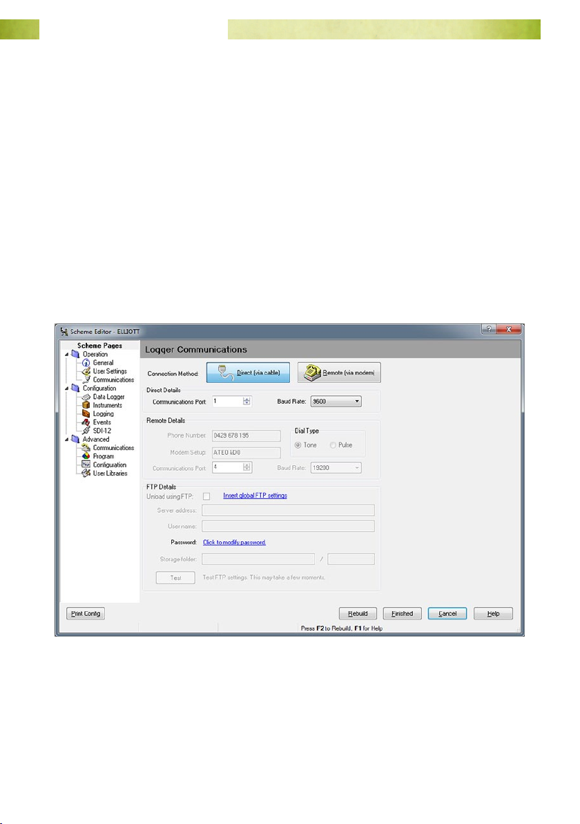
1. From the File menu select Edit Scheme.
2. Go to Operation ⇒ Communications.
To Unload Using a Cable Connected Between Your Computer and The Weather
station
1. Set the Communications Method to Direct (via cable).
2. Select the Communications Port your serial cable is attached to.
3. Leave the Baud Rate at 9600.
4. Select Finish to save your changes and close the scheme editor.
Page 39www.mea.com.au
Page 40
Junior Weather Station User Manual
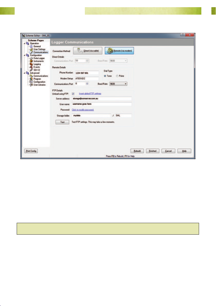
To Unload Using an Internet Connection
1. Set the Communications Method to Remote (via modem).
2. The Communications Port option will be greyed-out.
3. Leave the Baud Rate at 9600.
4. Under FTP Details, ensure that Unload using FTP is checked.
5. Select Finish to save your changes and close the scheme editor.
Hint: Magpie will remember the last connection method you used.
Page 40www.mea.com.au
Page 41
Junior Weather Station User Manual
Unload Data
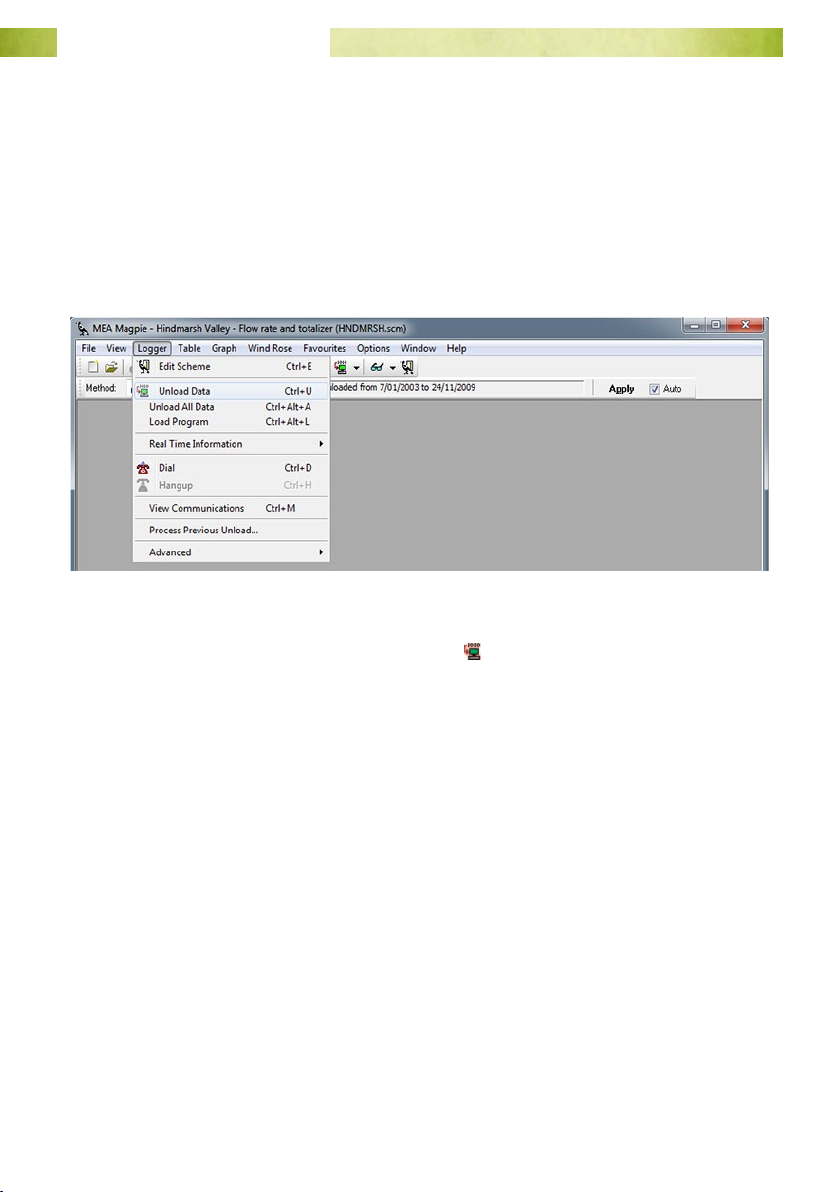
The unload process is the same for any connection method (for unloading via cable
you will need the appropriate cable connected between the data logger and your
computer).
To unload data:
1. From the menu bar select Logger ⇒ Unload data.
OR
Select the unload icon on the logger toolbar
.
Page 41www.mea.com.au
Page 42
Junior Weather Station User Manual
View Data
The Navigator
The navigator is used to select the period of data viewed.
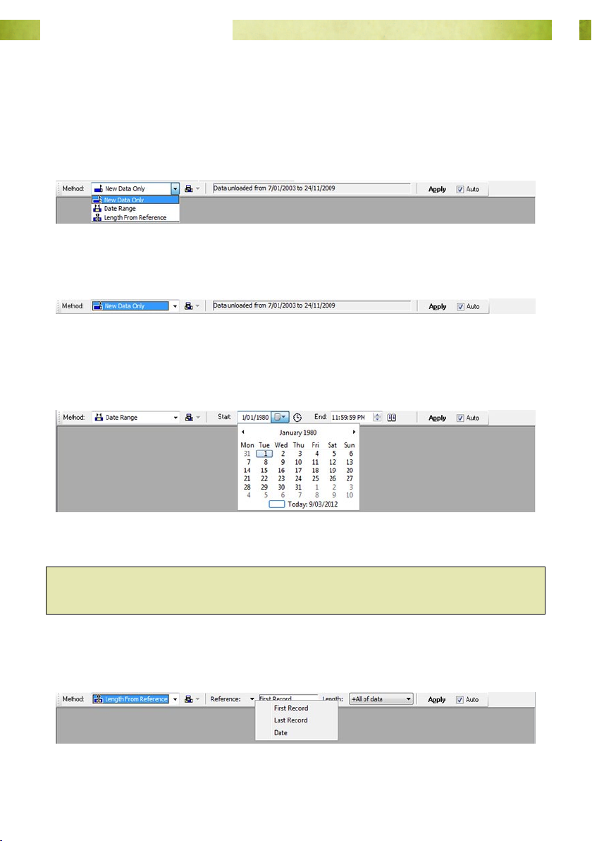
There are three methods, New Data Only, Date Range and Length From Reference.
New Data Only
Displays the data recorded since the last unload.
Date Range
Use the calendar and clock functions to select a precise range of data. Set the End date
and time rst.
Hint: If you want to adjust the date but can only see the clock icon, press it
anyway. The calendar will appear.
Length From Reference
Select a starting point for the data.
Page 42www.mea.com.au
Page 43
Junior Weather Station User Manual
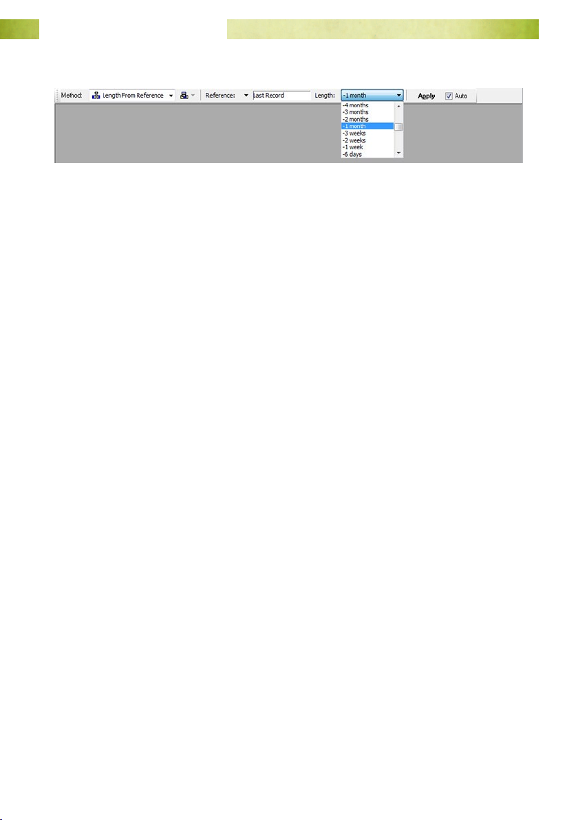
Then select the amount of data you want to see.
Select the Apply button, or check the Auto box to automatically apply navigator
settings whenever changes are made.
Page 43www.mea.com.au
Page 44
Junior Weather Station User Manual
Open a New Graph
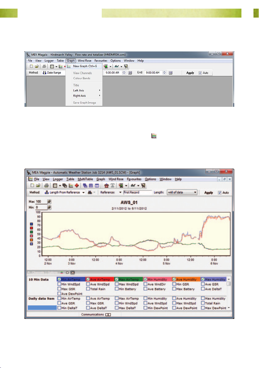
From the menu bar select Graph ⇒ New Graph.
OR
Select the New Graph icon from the scheme toolbar
.
A new graph will be blank by default. Turn traces on or o by checking or un-checking
the boxes in the channel selection grid.
The period of data displayed is determined by the navigator settings.
Page 44www.mea.com.au
Page 45
Junior Weather Station User Manual
Open a New Table
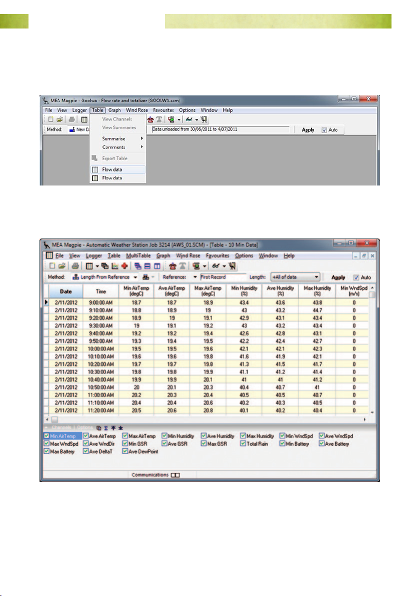
From the menu bar select Table, then select the table corresponding to the buer you
want to see.
A new table will show all columns by default. Turn columns on or o by checking or
un-checking the boxes in the channel selection grid.
The period of data displayed is determined by the navigator settings.
Only one buer is available at a time in a table.
Page 45www.mea.com.au
Page 46
Junior Weather Station User Manual
Favourite Graphs and Tables
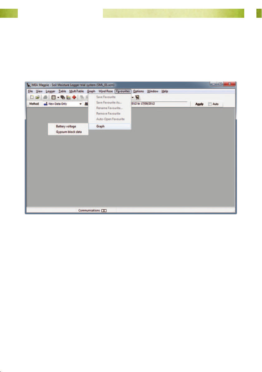
It is possible to save custom graphs and tables as Favourites. See the User Manual for
Magpie 3 for further details.
MEA may have created a number of favourite graphs and tables for you. Favourites are
created and accessed under the Favourites menu.
Favourites use the current navigator settings.
Page 46www.mea.com.au
Page 47
Junior Weather Station User Manual
Test the Packet Data Terminal
The Packet Data Terminal (PDT) automatically unloads the data logger every hour and
sends the data to the Internet using the mobile phone network.
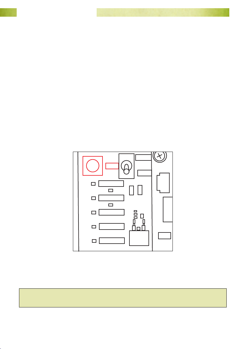
To test the operation of the PDT, remove the lid from the logger enclosure and fold
down the internal panel to reveal the circuit board. The TEST button and diagnostic
lights are located on the left-hand side of the circuit board.
Force a PDT Transfer
1. Ensure the weather station has been in operation long enough to log some data -
it will log every 10 minutes.
2. Press and hold the TEST button until all the diagnostic lights are lit.
3. The PDT will begin performing a normal unload from the data logger. This process
involves communicating with the logger, modem, network and FTP Server in
order to complete the process.
MANUAL
TEST
AUTO
LOGGER
MODEM
NETWORK
TRANSFER
ERROR
Fig. 29. The TEST button and diagnostic
lights for the PDT.
Hint: The Manual / Auto toggle switch should be in the Auto position for normal
operation.
Page 47www.mea.com.au
Page 48

Junior Weather Station User Manual
Observe the result
Each stage of the sequence is indicated by a green light. In order:
1. The LOGGER light will ash.
2. The MODEM light will ash, and then be steadily lit.
3. The NETWORK light will ash, and then be steadily lit.
4. The TRANSFER light will ash, and then be steadily lit for a brief period.
5. The MODEM light will ash.
6. All lights will go out.
If any part of the sequence fails then the red ERROR light will turn on in parallel with the
green light indicating the current stage of the sequence.
What the Lights Mean
The PDT has ve LEDs on the front panel to give status information. During normal
operation, the lights indicate when specic activity occurs. They also help to indicate
the source of a potential fault. If the LOGGER, MODEM or NETWORK lights are lit or
ashing whilst the ERROR light is on, an error has occurred at this stage. The table
below indicates the LED states for an unload.
= ashing green light
= green light on permanently
LGR MDM NET TFR ERR Activity
Indicates communication with the data logger.
The PDT is conguring or dialling the modem, or is accepting
a received call.
The modem is connected to the packet data network, or is
receiving a call.
PDT is negotiating with the packet data network.
PDT is logged on to the FTP server.
Data transfer is in progress.
Indicates a successful transfer.
Page 48www.mea.com.au
Page 49

Junior Weather Station User Manual
Review the Most Recent Result
When the PDT is inactive, all lights are o to save energy. The result of the most recent
transfer can be obtained by briey pressing the TEST button. If an error occurred then
the light corresponding to the source of error will ash (more than one green light may
ash) along with the red ERROR light. The lights will go out after a few seconds.
LGR MDM NET TFR ERR
A transfer has not been attempted since power was applied.
Logger information is lost or invalid.
Errors occurred during communication with data logger.
Failure occurred whilst making the connection.
Network authentication or FTP login failed.
Transaction error or timeout occurred with the FTP server.
Indicates a successful transfer.
Page 49www.mea.com.au
Page 50
Junior Weather Station User Manual
Testing FTP Unloading in Magpie 3
Select the Correct Communications Method
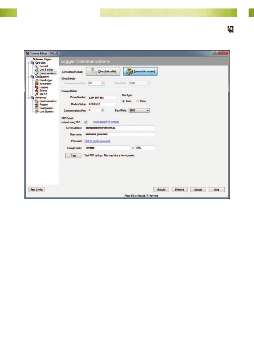
1. Start Magpie 3 and open the scheme.
2. Under the Logger menu, select Edit Scheme to open the Scheme Editor.
3. Go to Operation ⇒ Communications.
4. Make sure that the Connection Method is Remote (via modem) and that
Unload using FTP is checked.
5. Click Finished to close the Scheme Editor.
Page 50www.mea.com.au
Page 51
Junior Weather Station User Manual
Unload the Logger
1. From the Logger menu, select Unload Data.
2. Unloading will begin immediately.
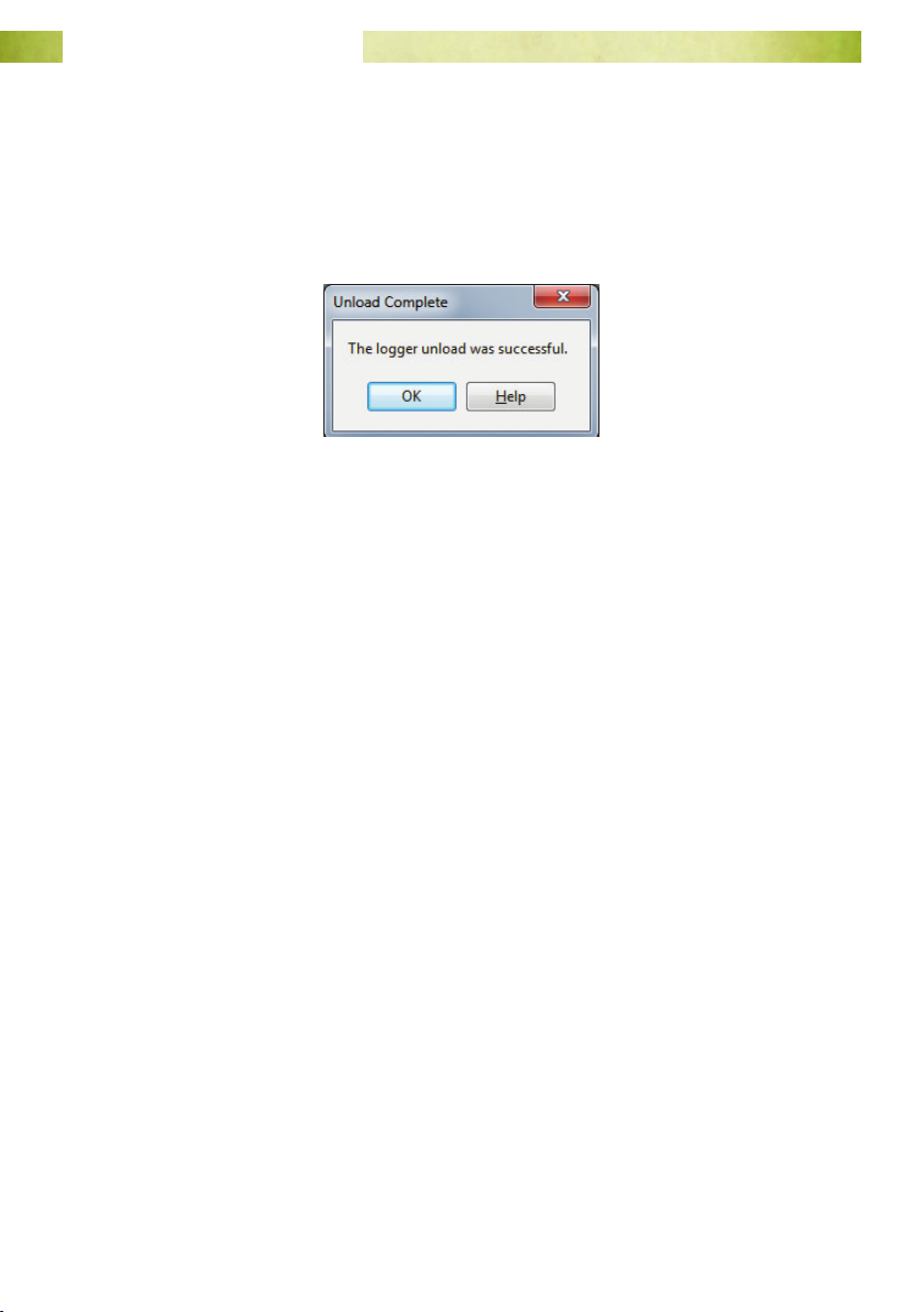
3. At the completion of the unload process, you will see the Unload Complete
dialog.
4. Open a new Graph or Table and check to see if data has been logged at the last
logical logging interval before the test transmission.
Page 51www.mea.com.au
Page 52
Junior Weather Station User Manual
How to Change Parameters for Virtual Instruments
Entering Your Altitude for the Delta T Instrument
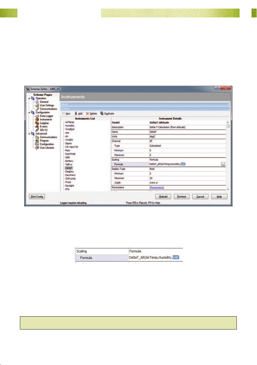
1. From the File menu select Edit Scheme.
2. When the scheme editor opens, go to Conguration ⇒ Instruments.
3. In Instruments List pane, left-click on the DeltaT instrument to highlight it.
4. In the Instrument Details pane, nd the Formula eld.
5. The formula will be expressed as DeltaT_Alt(AirTemp, Humidity, 140). The value
to the right of Humidity is the altitude in metres.
6. Over-type the altitude with the correct value for the site where the weather
station is located.
7. Click Finish to save your changes and close the scheme editor.
Hint: There is no need to re-program the data logger following this change.
Page 52www.mea.com.au
Page 53

Junior Weather Station User Manual
Changing the Threshold Temperature for Frost Hours
1. From the File menu select Edit Scheme.
2. When the scheme editor opens, go to Conguration ⇒ Instruments.
3. In Instruments List pane, left-click on the Frost instrument to highlight it.
4. In the Instrument Details pane, nd the Parameters eld.
5. Click on the statement InputChan=AT... to open the parameters window.
6. Over-type the Threshold with your preferred value then click OK to close the
parameters window.
7. Click Finish to save your changes and close the scheme editor.
Hint: There is no need to re-program the data logger following this change.
Page 53www.mea.com.au
Page 54
Junior Weather Station User Manual
Entering Latitude and Altitude for the ETo Instrument
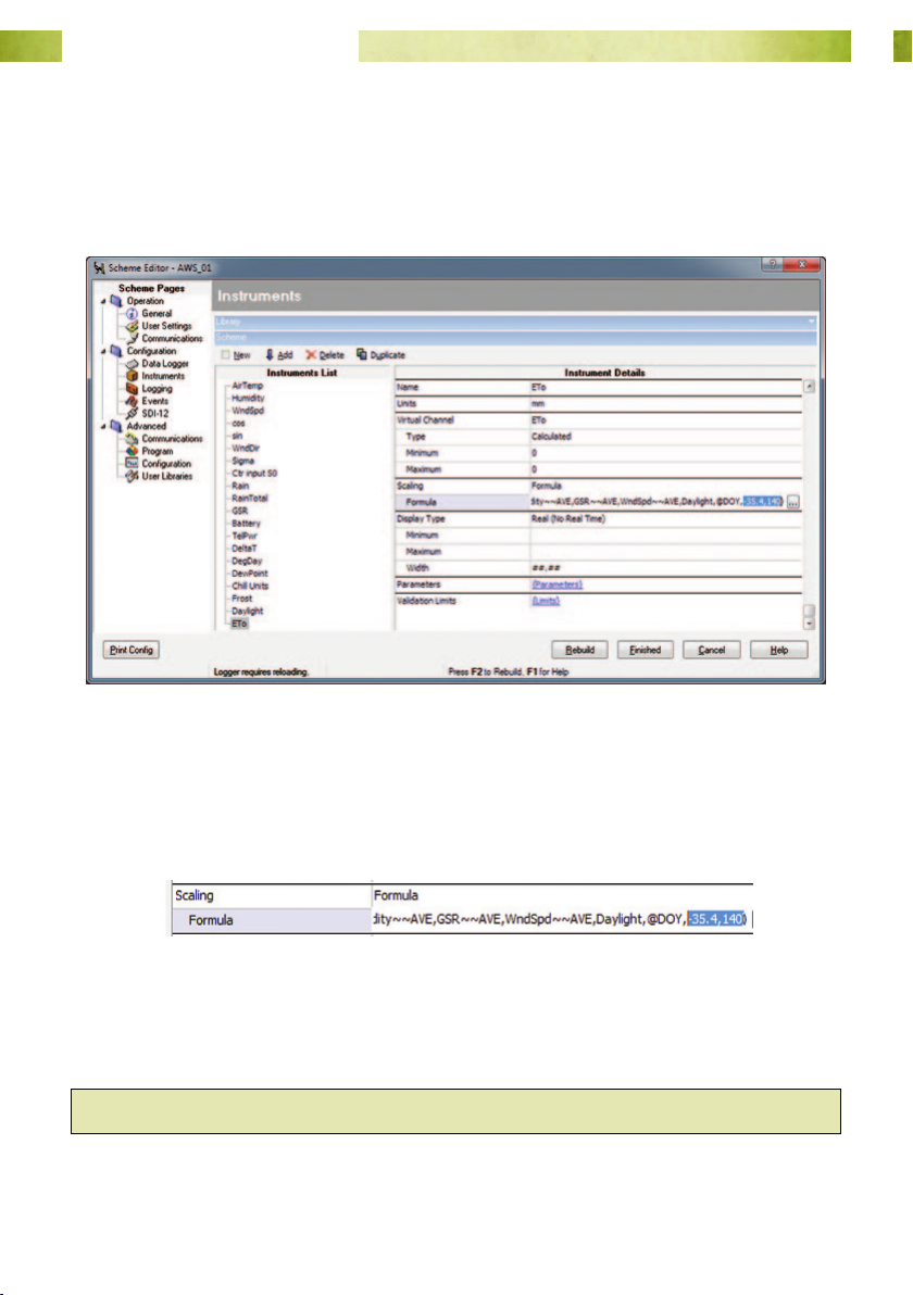
1. From the File menu select Edit Scheme.
2. When the scheme editor opens, go to Conguration ⇒ Instruments.
3. In Instruments List pane, left-click on the ETo instrument to highlight it.
4. In the Instrument Details pane, nd the Formula eld.
5. The formula will be expressed as FAOEvap(AirTemp~~MIN,AirTemp~~AVE,AirT
emp~~MAX,Humidity~~AVE,GSR~~AVE,WndSpd~~AVE,Daylight,@DOY,-
35.4,140). The values to the right of @DOY are the latitude in decimal degrees
and the altitude in metres.
6. Scroll to the far-right of the formula and over-type the latitude and altitude with
the correct values for the site where the weather station is located.
7. Click Finish to save your changes and close the scheme editor.
Hint: There is no need to re-program the data logger following this change.
Page 54www.mea.com.au
Page 55
Junior Weather Station User Manual
System Maintenance
Power Supply Maintenance
Failure of the system power supply will result in loss of data. The power supply is less
likely to fail if you monitor its performance and perform some basic maintenance
procedures.
Solar Panel
The system relies on the operation of the solar panel to maintain system power.
1. Inspect the panel weekly for signs of fouling by bird faeces, the build-up of dust
and obstruction by objects.
2. Clean the solar panel using a soft cloth and clean water or water mixed with mild
detergent. Do not use anything which could scratch the glass cover on the panel.
3. Keep surrounding vegetation trimmed so that it will not cast shadows on the
panels.
Battery Validation Errors
Your logging scheme has been congured to monitor the voltages of the system
battery. Additionally, the battery instrument has been agged to raise Validation Errors
if the logged battery voltage falls below a voltage relevant to the battery type and
application.
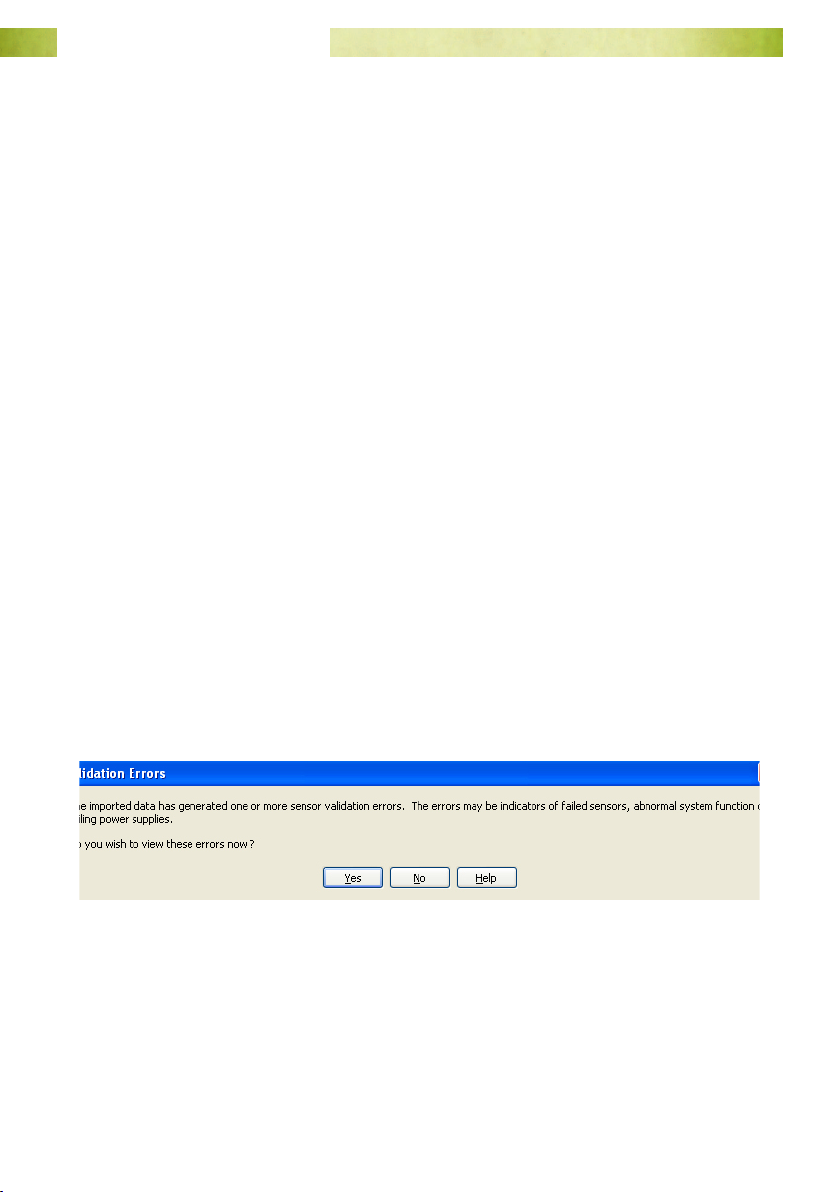
When downloading data for viewing in Magpie, you may see a dialog similar to the one
below:
Page 55www.mea.com.au
Page 56
Junior Weather Station User Manual
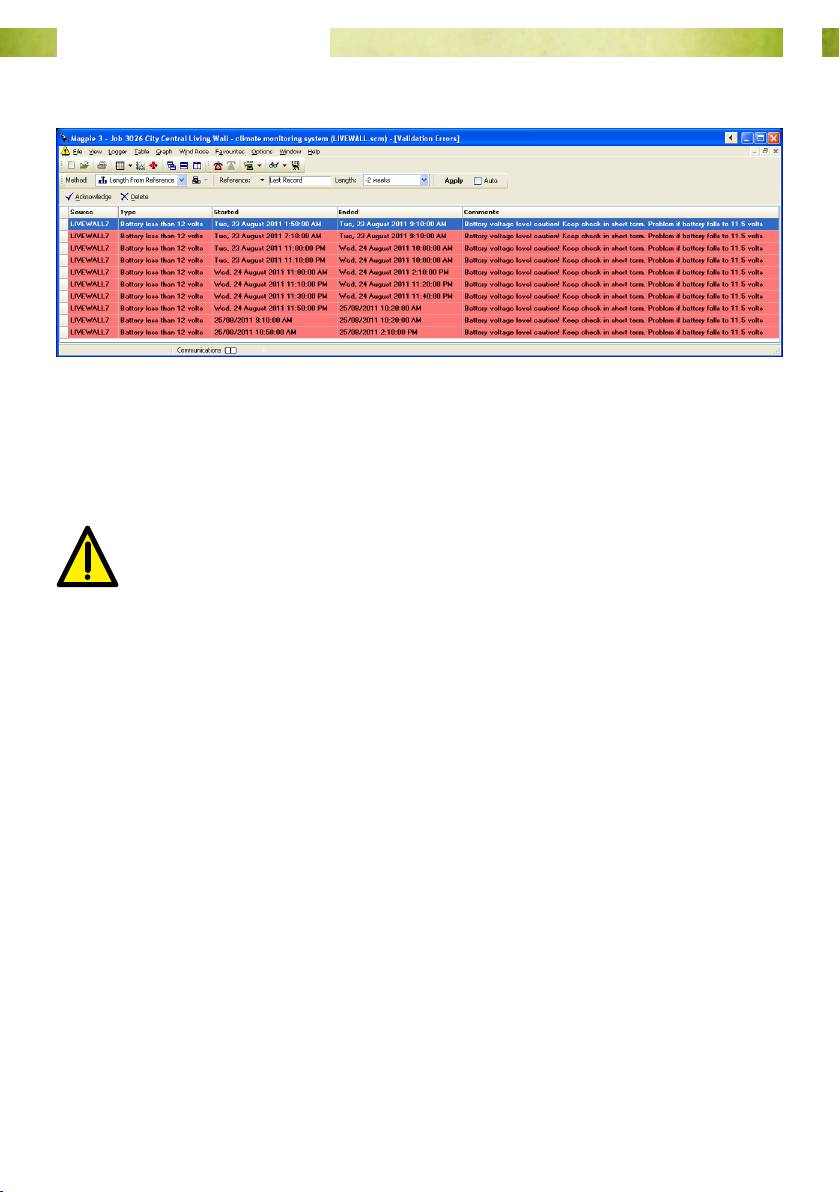
Select Yes to see the validation errors:
Fig. 30. The battery validation errors will be similar to the ones shown above.
System Battery
Pay attention to the logged values for the system battery. There will be a ‘Battery
voltage’ graph in the Favourites, Graphs menu.
If voltage values for the system battery fall to less than 11 V, the battery
may be damaged.
How to Replace the System Battery
The system battery should last for many years if the solar panel is kept clean. The
battery can be damaged if the solar panel is dirty and unable to provide adequate
charge, or if the sensor cables are damaged in such a way as to create an electrical
‘short’.
All batteries, no matter how well cared for, will eventually require replacement. Replace
the battery with a 12 V 7 Ah sealed lead acid battery. To replace the system battery:
1. Unload the data logger following the instructions at “Retrieving Measurements”
on page 39. Any stored data will be lost as soon as the system battery is
disconnected.
2. Follow the instructions at section “Install the System Battery” on page 32.
3. Re-program the data logger following the instructions at “Program the Data
Logger” on page 36.
Page 56www.mea.com.au
Page 57
Junior Weather Station User Manual
How to Replace the System Fuse
The fuse may blow if sensor cables are damaged or the battery is incorrectly connected.
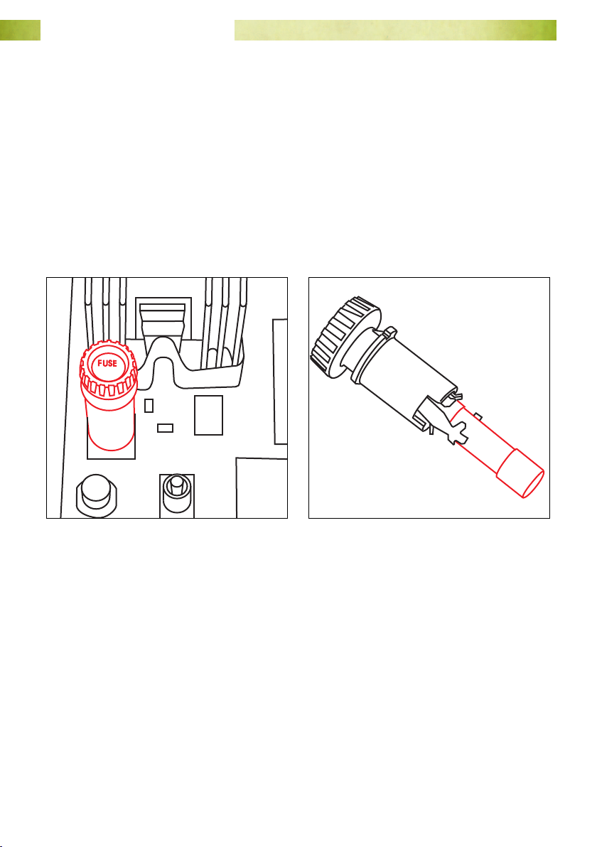
The system fuse is a 2 A 250 V 20 mm glass fuse. The fuse holder is identied in Fig. 31.
To replace the fuse:
1. Cover the solar panel and disconnect the system battery.
2. Pull down the internal plate to expose the circuit board.
3. Twist the top of the fuse holder anti-clockwise to remove it.
4. Replace the blown fuse with a known good fuse with the same specications.
Fig. 31. The system fuse holder. Fig. 32. The fuse is held captive in the lid.
5. Replace the top of the fuse holder re-connect the system battery and uncover the
solar panel. The PDT diagnostic lights below the fuse holder should commence a
chasing sequence, indicating that the PDT is starting up.
6. Attempt to unload the data logger - the logger’s backup battery may have been
able to retain data.
7. Regardless of whether the unload was successful, re-program the data logger as
per the instructions at “Program the Data Logger” on page 36.
Page 57www.mea.com.au
 Loading...