

Page 1
ACC5703
Operating Instructions
inertialSENSOR ACC5703
MICRO-EPSILON MESSTECHNIK GmbH & Co. KG
Königbacher Str. 15 · 94496 Ortenburg / Germany
Tel. +49 (0) 8542 / 168-0 · Fax +49 (0) 8542 / 168-90
info@micro-epsilon.de · www.micro-epsilon.com
Page 2

3-axes acceleration sensor
MICRO-EPSILON
MESSTECHNIK
GmbH & Co. KG
Königbacher Strasse 15
94496 Ortenburg / Germany
Tel. +49 (0) 8542 / 168-0
Fax +49 (0) 8542 / 168-90
e-mail info@micro-epsilon.de
www.micro-epsilon.com
Page 3

Contents
1. Safety ........................................................................................................................................ 5
1.1 Symbols Used ................................................................................................................................................. 5
1.2 Warnings .......................................................................................................................................................... 5
1.3 Notes on CE Marking ...................................................................................................................................... 6
1.4 Intended Use ................................................................................................................................................... 6
1.5 Proper Environment ......................................................................................................................................... 7
2. Functional Principle, Technical Data ...................................................................................... 8
2.1 Functional Principle ........................................................................................................................................ 8
2.2 Structure and Electrical Connection................................................................................................................ 8
2.3 Technical Data ................................................................................................................................................. 9
3. Delivery .................................................................................................................................. 12
3.1 Unpacking, Included in Delivery.................................................................................................................... 12
3.2 Storage ......................................................................................................................................................... 12
4. Installation and Assembly ...................................................................................................... 13
4.1 Sensor Cable Assembly ................................................................................................................................ 13
4.2 Sensor Assembly ........................................................................................................................................... 13
4.3 Pin Assignment .............................................................................................................................................. 15
4.4 Current and Voltage Output .......................................................................................................................... 15
4.5 Configuration of Sampling Rate and Low- and High-pass Filter .................................................................. 19
4.6 Digital Output RS485 ..................................................................................................................................... 20
5. Operation ................................................................................................................................ 21
6. Liability for Material Defects ................................................................................................. 21
4.4.1 Continuous Operation Mode ........................................................................................................ 16
4.4.2 Switching Operation Mode ........................................................................................................... 17
ACC5703
7. Service, Repair ...................................................................................................................... 22
8. Decommissioning, Disposal ................................................................................................. 22
Page 4

Appendix
A 1 Accessories ............................................................................................................................ 23
A 2 PC Software sensorTOOL ...................................................................................................... 23
A 3 Factory Settings ..................................................................................................................... 23
A 4 Digital Interface RS485 .......................................................................................................... 24
A 4.1 Hardware Interface ........................................................................................................................................ 24
A 4.2 Protocol .......................................................................................................................................................... 24
A 4.2.1 Reading Measurement Data......................................................................................................... 25
A 4.2.2 Example Transmission of a Measurement Value ......................................................................... 29
ACC5703
Page 5
Safety
1. Safety
System operation assumes knowledge of the operating instructions.
1.1 Symbols Used
The following symbols are used in these operating instructions:
Indicates a hazardous situation which, if not avoided,
may result in minor or moderate injury.
Indicates a situation that may result in property damage if not avoided.
Indicates a user action.
i
1.2 Warnings
Connect the power supply and the display/output device according to the safety regulations for electrical
equipment.
> Risk of injury
> Damage to or destruction of the sensor
The supply voltage must not exceed the specified limits.
> Damage to or destruction of the sensor
Indicates a tip for users.
ACC5703
No sharp or heavy objects should be allowed to affect the cables. Avoid folding the cables. Do not bend
more tightly than the minimum bending radius of the cables.
> Damage or destruction of the cable, failure of the measuring device
Do not crush the cable. Protect the sensor cable against damage.
> Damage or destruction of the cable, failure of the measuring device, data loss
Ensure that the coupling nuts of the connectors are firmly tightened.
> Damage or destruction of the cable, failure of the measuring device
Page 5
Page 6

Safety
1.3 Notes on CE Marking
The following apply to the ACC5703:
- EU Directive 2014/30/EU
- EU Directive 2011/65/EU
Products which carry the CE mark satisfy the requirements of the EU directives cited and the European
harmonized standards (EN) listed therein. The EU Declaration of Conformity is available to the responsible
authorities according to EU Directive, article 10, at:
MICRO-EPSILON MESSTECHNIK
GmbH & Co. KG
Königbacher Straße 15
94496 Ortenburg /Germany
The measuring system is designed for use in industrial environments and meets the requirements.
1.4 Intended Use
The ACC5703 is designed for use in industrial applications. It is used for
measuring acceleration
measuring vibration of manoeuvrable components
- The system must only be operated within the limits specified in the technical data, see 2.3.
- The sensor must be used in such a way that no persons are endangered or machines and other material
goods are damaged in the event of malfunction or total failure of the sensor.
- Take additional precautions for safety and damage prevention in case of safety-related applications.
ACC5703
Page 6
Page 7

Safety
1.5 Proper Environment
- Protection class: 1 IP 67
- Operating temperature: -40 ... +85 °C (-40 ... +185 °F)
- Storage temperature: -40 ... +85 °C (-40 ... +185 °F)
- Ambient pressure: Atmospheric pressure
1) With M12 connector
ACC5703
Page 7
Page 8
Functional Principle, Technical Data
2. Functional Principle, Technical Data
2.1 Functional Principle
With the principle of an acceleration sensor, forces that change the velocity of an object are measured and
transformed into an electric output signal.
Therefore the sensor is mounted on the maneuverable component. The expected moves correspond to the
measurement axes. The included MEMS-Element converts the acceleration into a usable electric signal.
-z
Fig. 1 Three axes acceleration sensor
2.2 Structure and Electrical Connection
The sensor is ready for operation immediately after connecting the power supply and will provide the acceleration as electric value at the analog output.
The ACC5703 is available with analog (current, voltage and switching output) as well as RS485 interface for
configuring of the sensor using the software.
Power supply and signal output are connected through a 8-contact (M12) connector on the sensor’s housing.
+z
+y
-y
+x
-x
ACC5703
Page 8
Page 9

Functional Principle, Technical Data
2.3 Technical Data
Model
Number of axes
Measuring range
Resolution
Noise
Sensitivity
(analog output)
Zero
Linearity
Frequency range
Sampling rate
Cross axis sensitivity
Temperature stability
Supply voltage
Power consumption
Temperature range
Digital interface
Analog output
Switching output
Protection class
Digital
Analog
Current
Voltage
Operation
Storage
ACC5703-8
3
± 0 g … ± 8 g (configurable)
0.016 mg
Current: < 0.24 mg / voltage < 0.31 mg
Typ. 30 µg / √Hz
< 4 mA/g
< 1 V/g
12 mA or 2.5 V
Typ. 0.45 % FSO
0 ... 1000 Hz (configurable)
Up to 4 kHz
1 % FSO
Typ. ± 0.2 mg / K
5 … 32 VDC
< 3 W
-40 … +85 °C (-40 ... +185 °F)
-40 … +85 °C (-40 ... +185 °F)
RS485
Current 4 … 20 mA (max. 390 Ω)
Voltage 0.5 … 4.5 V (min. 1 KΩ)
0 / 5 V (min. 1 KΩ)
IP 67 (plugged state)
ACC5703
Page 9
Page 10

Functional Principle, Technical Data
Model
Shock
Weight
Material
Installation
Connection
Start-up time
FSO = Full Scale Output
All specifications valid at a room temperature of +25 °C (+77 °F)
Article designation
ACC 5703 -8 -SA -U/I
Output
U = voltage 0.5 ... 4.5 V,
I = current 4 ... 20 mA,
switching output 0 / 5 V
Connection:
SA = axial plug
Measuring range in g
High Performance acceleration sensor
(1500 g, 0.5 ms, half-sine shock, 3 x in each direction)
Screw connection via mounting holes (M4)
ACC5703-8
DIN EN 60068-2-27
Approx. 250 g
Die-cast aluminum
M12 connector, 8-pin
< 500 ms
ACC5703
Page 10
Page 11

Functional Principle, Technical Data
Response time
Sampling frequency [Hz] Time [ms]
4000 0.88
2000 1.25
1000 2.03
500 3.51
250 6.52
125 12.59
62.5 24.43
31.25 47.84
15.625 96.5
7.813 189.83
3.906 384.56
Fig. 2 Table response time
ACC5703
Page 11
Page 12

Delivery
3. Delivery
3.1 Unpacking, Included in Delivery
1 Sensor ACC5703
1 Operating Instructions
Carefully remove the components of the measuring system from the packaging and ensure that the
goods are forwarded in such a way that no damage can occur.
Check the delivery for completeness and shipping damage immediately after unpacking.
If there is damage or parts are missing, immediately contact the manufacturer or supplier.
Optional accessories are available in the appendix, see A 1.
3.2 Storage
Storage temperature: -40 ... +85 °C (-40 ... +185 °F)
Humidity: 5 - 95 % (non-condensing)
ACC5703
Page 12
Page 13

Installation and Assembly
4. Installation and Assembly
4.1 Sensor Cable Assembly
No sharp or heavy objects should be allowed to affect the cables. Avoid folding the cables. Do not bend
more tightly than the minimum bending radius of the cables.
> Damage or destruction of the cable, failure of the measuring device
Do not crush the cable. Protect the sensor cable against damage.
> Damage or destruction of the cable, failure of the measuring device
Ensure that the coupling nuts of the connectors are firmly tightened.
> Damage or destruction of the cable, failure of the measuring device
4.2 Sensor Assembly
The sensor is fixed into place with the help of two through bores for M4 screws.
The sensor is mounted at the manoeuvrable component. The orientation of the measurement axes x, y, z is to
be respected in relation to the expected moves of the component.
+y
ACC5703
-y
+x
-z
-x
+z
Fig. 3 Installation orientation, measurement axis
Page 13
Page 14

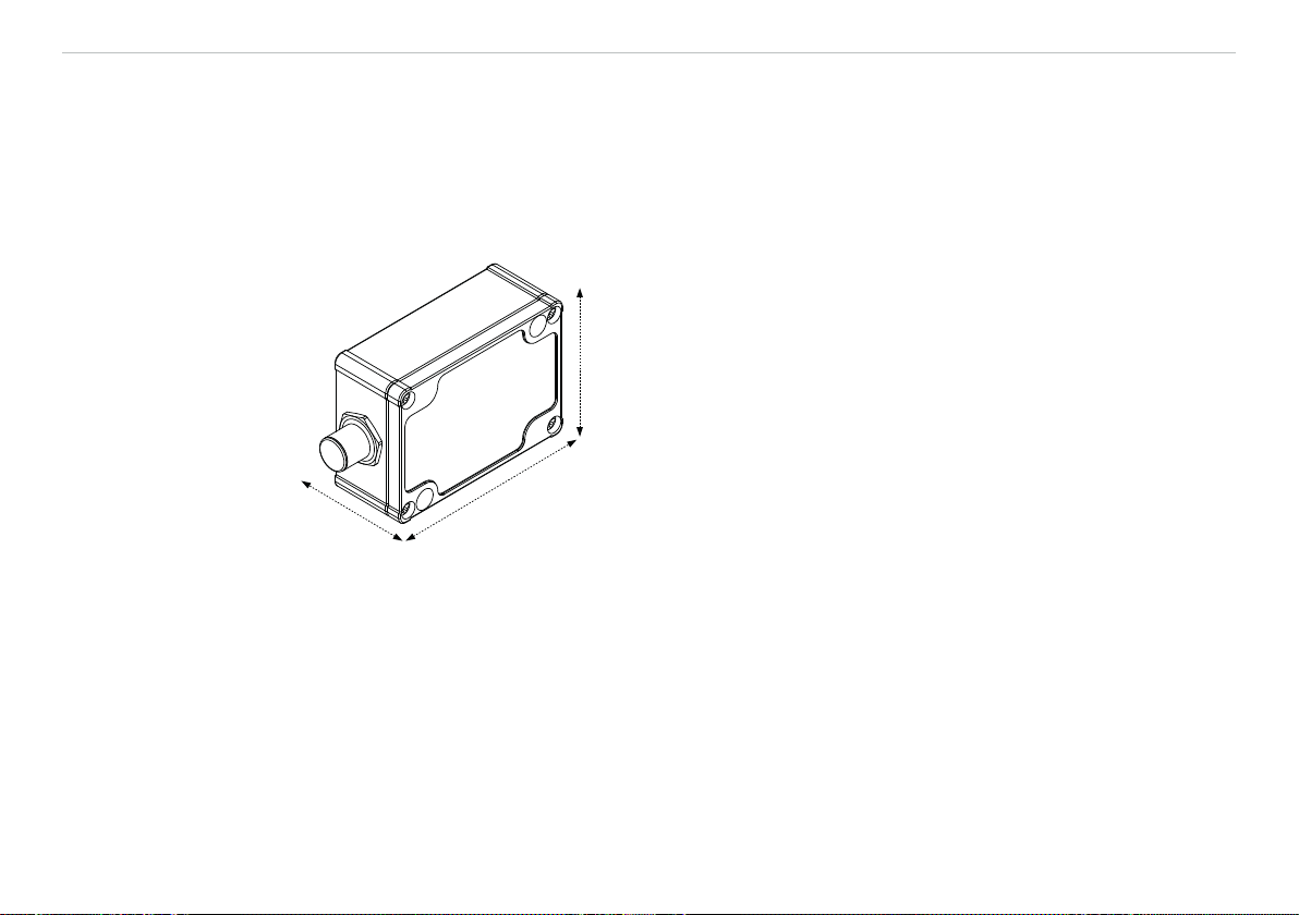
Installation and Assembly
12.5 (.49)
12 (.47)
5.5 (.22)
ACC5703
Mounting holes
for M4 screws
53 (2.09)
5.5 (.22)
12 (.47)
76 (2.99)
Fig. 4 Dimensional drawing, dimensions in mm (inches), not to scale
26.5 (1.04)
6 (.24)
24 (.94)
Page 14
Page 15

Installation and Assembly
4.3 Pin Assignment
Connect the open cable end in accordance with the color coding, see Fig. 5.
Pin 1Color
2
Description
45 °
1 White Output channel 2
2 Brown GND (Output)
3 Green Output channel 3
2
3
4
8
1
4 Yellow RS485+
5 Gray Output channel 1
6 Black/pink GND (Supply)
5
7
6
7 Blue RS4858 Red Supply + View of solder pin side, 8-pin,
A-coded, female connector
Fig. 5 Pin assignment of the 8-pin, A-coded, female connector
1) - SA - Connector
2) PCx/8-M12 Power supply and output cable, see A 1.
4.4 Current and Voltage Output
The sensor makes the acceleration value available as analog output variable either as current or voltage
value on separate pins.
Three output channels can be configured independently with the following settings.
Each output channel can be operated in continuous operation mode or switching operation mode.
Versorgungsspannung 5 - 32 V
Analogausgangskanal 1
Sensor
Analogausgangskanal 2
Analogausgangskanal 3
Digitalausgang RS485
ACC5703
Fig. 6 Current and voltage output
Page 15
Page 16

Installation and Assembly
Selection of measurement axis (x, y, z) at every channel possible
Off (zero output)
Continuous mode, current 4 - 20 mA
Continuous mode, voltage 0.5 - 4.5 V
Switching mode, voltage 0 - 5 V
Fig. 7 Operation modes of the analog output channels
4.4.1 Continuous Operation Mode
The sensor makes the acceleration value available as analog output variable either as current or voltage
value on separate pins, depending on the configuration using the software tool of Micro-Epsilon.
In this process, the symmetrical measurement range in the unit g is scaled to the respective analog range.
The sensitivity increases with decreasing measurement range as only a small acceleration range is scaled to
the same output range, see Fig. 8, see Fig. 9.
ACC5703
20
18
16
14
12
10
8
6
Current in mA
4
-2 g
-4 g
-8 g
0 g
Acceleration in g
+2 g
+4 g
+8 g
5
4.5
4
3.5
3
2.5
2
1.5
Voltage in V
1
0.5
0
-2 g
-4 g
-8 g
0 g
Acceleration in g
Fig. 8 Scaling of the acceleration measurement range to analog output variable current or voltage
+2 g
+4 g
+8 g
Page 16
Page 17

Installation and Assembly
Range digital [g] Resolution digital
RS485 [mg]
Resolution analog
current [mg]
Resolution analog
voltage [mg]
Sensitivity analog
current [mA/g]
Sensitivity analog
voltage s[V/g]
±2 0.004 0.06 0.076 4.0 1.0
±4 0.008 0.12 0.15 2.0 0.5
±8 0.016 0.24 0.31 1.0 0.25
Fig. 9 Examples of resolution (mg) and sensitivity (mA/g) depending on the configured measurement range
4.4.2 Switching Operation Mode
The switching mode, configurable via Software, switches the analog voltage output to 5 V when the acceleration value reaches
the trigger-level “on-level” and switches back to 0 V when the acceleration value falls below the “off-level”.
Selection of measurement axis (x, y, z) (vector addition (xy, xz, yz, xyz)
(x
2
+ y
2
2
possible at every channel)
+ z
)
On-level [g] Switching hysteresis
Off-level [g] Rise- / Fall-time < 10 μs
Edge triggered (switching when reaching the level considering the minimum hold time, see Fig. 13)
Edge triggered with delay (switching after specified time during which the level is reached permanently)
Fig. 10 Settings of switching mode
That functionality can be used, for example, as safety feature which switches off a machine if high vibrations occur. The triggerlevels take effect symmetrically, i.e. in the positive and negative acceleration range at the same absolute value, see Fig. 11.
The output values at the digital interface in switching mode are either zero or equal to the “on-level” as long as the trigger condition is met.
The duration of the rising and falling edge is t < 10 μs, see Fig. 12.
Two different modes are selectable:
- Edge triggered, i.e. immediate switching when reaching the trigger-level.
- Edge triggered with delay, i.e. switching after specified time during which the trigger-level is reached permanently.
The minimum hold time of the switching status depends on the selected sampling rate, see Fig. 13.
ACC5703
Page 17
Page 18

Installation and Assembly
5
4.5
4
3.5
3
2.5
2
1.5
Voltage in V
1
0.5
0
-2 g
on-level off-level off-level on-level
-4 g
-8 g
0 g
Acceleration in g
+2 g
+4 g
+8 g
Fig. 11 Hysteresis of the trigger-levels in switching
operation
5
4.5
4
3.5
3
2.5
2
Trigger
1.5
Voltage in V
1
0.5
Trigger
Sampling rate (Hz) Minimum hold time of
switching status (ms)
4000 25
2000 25
1000 25
500 26
250 28
125 32
62.5 32
31.25 32
15.625 64
7.8125 128
3.90625 256
Fig. 13 Minimum hold time of the switching status
0
5 10 15
0
20 25
30
35 40 45
50
t in µs
Fig. 12 Rising and falling edge of the voltage output in
switching mode, t < 10 µs
ACC5703
Page 18
Page 19

Installation and Assembly
Amplitude in g
4.5 Configuration of Sampling Rate and Low- and High-pass Filter
Parameters, like sampling rate or filter frequencies, are adaptable in a wide range in order to match the respective application.
The high-pass is configured to reduce influences of low frequencies especially to hide earth acceleration. The
low-pass is configured to hide disturbances at high frequency.
ACC5703
1
Frequency in Hz
Fig. 14 Configuration of filter to reduce influences
2
1 Highpass to hide earth acceleration
2 Lowpass to hide disturbances
Page 19
Page 20

Installation and Assembly
Different low-pass filter settings, see Fig. 15, cause the sampling rate to change respectively. The chosen lowpass frequencies furthermore have influence on the available high-pass filter options.
Low-pass f
(configurable)
1000 4000
500 2000
LP
[Hz]
Sampling rate [Hz] High-pass f HP [Hz]
(optional, configurable)
1
1
0.00952 … 9.88
0.00476 … 4.94
250 1000 0.00238 … 2.47
125 500 0.00119 … 1.235
62.5 250 0.000595 … 0.6175
31.25 125 0.0002975 … 0.30875
15.625 62.5 0.00014875 … 0.154375
7.813 31.25 7.4375e-5 … 0.0771875
3.906 15.625 3.71875e-5 … 0.03859
1.953 7.813 1.859e-5 … 0.0193
0.977 3.906 9.296e-6 … 0.009648
Fig. 15 Table dependency between sampling rate and low- and high-pass settings
1) Digital interface RS485 is enabled only up to 1000 Hz sampling rate. At higher rates only the analog output
is active.
4.6 Digital Output RS485
You can read out the measured data in digital form using the RS485 interface in a sampling rate up 1000 Hz.
For higher sampling rates only the analog operation is possible. The PC software sensorTool, see A 2,
permits configuration of the sensor and the visualization of the measured data, see A 1. The bus protocol
required to read out the measured data in your own applications is described in the appendix, see A 4.
Additionally, you can use the IF1032/ETH interface converter by MICRO-EPSILON MESSTECHNIK GmbH &
Co. KG, to read out the measured data via Ethernet.
ACC5703
Page 20
Page 21

Operation
5. Operation
The measurement device is already calibrated when delivered. Calibration by the user is not necessary. After
connection to the operating voltage, the sensor is immediately ready for operation and independently initiates
the measurement.
Additionally, the digital RS485 interface is ready to react to enquiries by the master (periodic retrieval of measured data).
For sensor configuration please use the power supply and output cable with USB/RS485 converter, see A 1
as well as the software of MICRO-EPSILON.
Allow the sensor to warm up for approximately 10 minutes after connection of the voltage supply.
i
6. Liability for Material Defects
All components of the device have been checked and tested for functionality at the factory. However, if defects occur despite our careful quality control, MICRO-EPSILON or your dealer must be notified immediately.
The liability for material defects is 12 months from delivery.
Within this period, defective parts, except for wearing parts, will be repaired or replaced free of charge, if the
device is returned to MICRO-EPSILON with shipping costs prepaid. Any damage that is caused by improper
handling, the use of force or by repairs or modifications by third parties is not covered by the liability for material defects. Repairs are carried out exclusively by MICRO-EPSILON.
Further claims can not be made. Claims arising from the purchase contract remain unaffected. In particular,
MICRO-EPSILON shall not be liable for any consequential, special, indirect or incidental damage. In the interest of further development, MICRO-EPSILON reserves the right to make design changes without notification.
For translations into other languages, the German version shall prevail.
ACC5703
Page 21
Page 22

Service, Repair
7. Service, Repair
If the sensor is defective, please send us the affected
parts for repair or exchange.
If the cause of a fault cannot be clearly identified, please
send the entire measuring system to:
MICRO-EPSILON MESSTECHNIK
GmbH & Co. KG
Königbacher Str. 15
94496 Ortenburg / Germany
Tel. +49 (0) 8542 / 168-0
Fax +49 (0) 8542 / 168-90
info@micro-epsilon.de
www.micro-epsilon.com
8. Decommissioning, Disposal
Remove the power and output cable from the sensor.
Incorrect disposal may cause harm to the environment.
Dispose of the device, its components and accessories, as well as the packaging materials in compli-
ance with the applicable country-specific waste treatment and disposal regulations of the region of use.
ACC5703
Page 22
Page 23

Appendix | Accessories
Appendix
A 1 Accessories
Designation Description
PC3/8-M12 Power supply and output cable, 3 m long
PC5/8-M12 Power supply and output cable, 5 m long
PC10/8-M12 Power supply and output cable, 10 m long
PC10/8-M12 Power supply and output cable, for drag chain use, 10 m long
PC15/8-M12 Power supply and output cable, 15 m long
PC2/8-Sub-D Power supply and output cable with USB / RS485 converter, 2,8 m long
A 2 PC Software sensorTOOL
You will find the software for the sensor for free at:
www.micro-epsilon.com
A 3 Factory Settings
Low-pass filter: 62,5 Hz
Sampling rate: 250 Hz
High-pass filter: Disabled
Measurement range: ±2 g
Sensitivity: 4 mA/g or 1 V/g
Output signal: 4 ... 20 mA
Active axes: Channel 1: “x”, channel 2: “y”, channel 3: “z”, see Fig. 3
ACC5703
Page 23
Page 24

Appendix | Digital Interface RS485
A 4 Digital Interface RS485
A 4.1 Hardware Interface
The interface is a half-duplex RS485 interface, which means that one cable pair is jointly used for sending and
receiving.
Baud rate 230400 b/s
Data format 1 start bit, 8 data bits, 1 parity bit even, 1 stop bit
Bus address 126
Fig. 16 Settings of the RS485 interface
A terminating resistance of 120 Ω is required between the A- and B-line of the RS485 interface at the beginning and the end of the RS485 bus. A terminating resistor of the RS485 line is not incorporated in the sensor.
It is therefore allowed to connect several sensors to one bus cable.
A 4.2 Protocol
The sensor acts as RS485 slave. As the system uses a half-duplex protocol, only the master can initiate
communication. Each device at the RS485 bus requires its own address. The master sends an enquiry with
the destination address to the bus and only the slave with this address answers accordingly.
ACC5703
Page 24
Page 25

Appendix | Digital Interface RS485
A 4.2.1 Reading Measurement Data
Master: Request data
Byte: SD DA SA FC FCS ED
Value: 0x10 x x 0x4C x 0x16
Slave: Response data
Byte: SD LE LE
Value: 0x68 x x 0x68 x x 0x08 x x 0x16
Designations
SD Start Delimiter
LE Length (number of bytes without SD, LE, LE rep, SD rep, FCS, ED)
LE rep LE repeated
SD rep SD repeated
DA Destination Address (default 0x7E = 126)
SA Source Address (e. g. 0x01)
FC Function Code
FCS Checksum
ED End Delimiter
Data[] Measurement data, variable number, little endian
The measurement data consists of one status byte, one measured values counter, number of measured values, and the measured data. The measured values counter increases continuously with each sampled value.
It represents the number of measured values buffered in the sensor since the last enquiry by the master and
therefore represents the number of the measured values transmitted in this package (floats).
FCS
SD
rep
(0x10: datagram without data, 0x68: datagram with variable length)
(sum of all bytes without SD, LE, LE rep, SD rep, FCS, ED, overflow at 256)
rep
DA SA FC Data[] FCS ED
FCS
ACC5703
Page 25
Page 26

Appendix | Digital Interface RS485
A new sampled measurement value is saved to the internal buffer of the sensor. The maximum number of
values which can be saved is 19 for each measurement axis. Therefore, an enquiry by the master must reach
the sensor within a certain time, that depends on the set sampling rate, in order to read the content from the
internal memory and ensure uninterrupted sampling (periodic enquiry).
- Example 1 kHz: 19 values * 1 ms = 19 ms
- Example 250 Hz: 19 values * 4 ms = 76 ms
If the enquiries are not made in time, error flag 0x01 is set in the status byte. The measurement is continued
anytime, i.e. the values in the buffer which are not read will be overwritten with updated measurements. The
buffer content is, therefore, always updated. The overflow error flag is deleted automatically as soon as the
master resumes its periodic enquiries.
The analog output remains unaffected by this. The first measurement value in the Data[] package is the oldest measured value. A measured value is represented as 4-byte float data type in the unit [g]1.
ACC5703
1 g = 9.81
1)
m
2
s
Page 26
Page 27

Appendix | Digital Interface RS485
Byte Meaning Data format
Data[0] Status byte (contains error flags, normally 0x00 8 bit
Data[1] Long term values counter [bit 0:7] Uint 32 bit
Data[2] Long term values counter [bit 8:15]
Data[3] Long term values counter [bit 16:23]
Data[4] Long term values counter [bit 24:31]
Data[5] Number of measured values in this package 8 bit
Data[6] Padding byte 8 bit
Data[7] Padding byte 8 bit
Data[8] Measured value 1 [bit 0:7] Float 32 bit
Data[9] Measured value 1 [bit 8:15]
Data[10] Measured value 1 [bit 16:23]
Data[11] Measured value 1 [bit 24:31]
Data[12] Measured value 2 [bit 0:7] Float 32 bit
Data[13] Measured value 2 [bit 8:15]
Data[14] Measured value 2 [bit 16:23]
Data[15] Measured value 2 [bit 24:31]
... ... ...
Data[n]
n=8+(4*Data [5])
Data[n+1] Measured value 1 y-axis [bit 8:15]
Data[n+2] Measured value 1 y-axis [bit 16:23]
Data[n+3] Measured value 1 y-axis [bit 24:31]
Measured value 1 y-axis [bit 0:7] Float 32 bit
ACC5703
Page 27
Page 28

Appendix | Digital Interface RS485
Byte Meaning Data format
Data[n+4] Measured value 1 y-axis [bit 0:7] Float 32 bit
Data[n+5] Measured value 1 y-axis [bit 8:15]
Data[n+6] Measured value 1 y-axis [bit 16:23]
Data[n+7] Measured value 1 y-axis [bit 24:31]
... ... ...
Data[n+m]
m=4*Data[5]
Data[n+m+1] Measured value 1 z-axis [bits 8:15]
Data[n+m+2] Measured value 1 z-axis [bits 16:23]
Fig. 17 Encoding of Measured Data in the Transmission Protocol
Measured value 1 z-axis [bits 0:7] Float 32 bit
ACC5703
Page 28
Page 29

Appendix | Digital Interface RS485
A 4.2.2 Example Transmission of a Measurement Value
Master: Request data
Byte: SD DA SA FC FCS ED
Value: 0x10 0x7E 0x01 0x4C 0xCB 0x16
DA = Destination Address = 0x7E = 126 (slave address)
SA = Source Address = 0x01 (master address)
FCS = Checksum = 0x7E + 0x01 + 0x4C = 0xCB
Slave: Response data
Byte: SD LE LE
Value: 0x68 1B 1B 0x68 0x01 0x7E 0x08 x 0x67 0x16
4 measured values = 4 x float = 4 x 4 bytes = 16 data bytes
LE = Length = 16 data bytes + 11 bytes (DA, SA, FC, 1xstatus, 4xstatus, 4xcounter, 1xnumber, 2xpadding
byte) = 0x1B = 27
DA = Destination Address = 0x01 (Master)
SA = Source Address = 0x7E = 126 (Slave)
FCS = Checksum = 0x01 + 0x7E + 0x08 + 0x00 (status) + 0x04 (counter) ... = 0x67 (note overflow at 256
each time = reset sum to zero)
FCS
= 126 + 1 + 76 = 203 (no overflow) at 256)
rep
SD
rep
DA SA FC Data[] FCS ED
FCS
ACC5703
Page 29
Page 30

MICRO-EPSILON MESSTECHNIK GmbH & Co. KG
Königbacher Str. 15 · 94496 Ortenburg / Germany
Tel. +49 (0) 8542 / 168-0 · Fax +49 (0) 8542 / 168-90
info@micro-epsilon.de · www.micro-epsilon.com
X9751392-A011068HDR
MICRO-EPSILON MESSTECHNIK
*X9751392-A01*
 Loading...