

Page 1
IEEE 802.11 b/g/n (max. 150 Mbit/s)
WEP/WPA/WPA2 Verschlüsselung
m2m Standard 03/15
Mit Sicherheit verbunden.
Configuration Manual
for MX7 Series Routers
Page 2

mdex AG • Bäckerbarg 6 • 22889 Tangstedt
USED SYMBOLS
Used symbols
Danger – important notice, which may have an influence on the user?s safety or the function
of the device.
Attention – notice on possible problems, which can arise in specific cases.
Information, notice – information, which contains useful advice or special interest.
Firmware version
This manual refers to firmware version 5.1.0 (March 17, 2015).
GPL licence
Source codes under GPL licence are available free of charge by sending an email to:
Router version
Properties and settings of router associated with the GSM connection is not available in mdex
Router MX700.
Manual issued July 9, 2015
i
Page 3

mdex AG • Bäckerbarg 6 • 22889 Tangstedt
CONTENTS
Contents
1 Configuration over web 1
1.1 Secured access to web configuration . . . . . . . . . . . . . . . . . . . . . . . . 2
1.2 General . . . . . . . . . . . . . . . . . . . . . . . . . . . . . . . . . . . . . . . . 2
1.2.1 Mobile Connection . . . . . . . . . . . . . . . . . . . . . . . . . . . . . . 2
1.2.2 Primary LAN . . . . . . . . . . . . . . . . . . . . . . . . . . . . . . . . . 3
1.2.3 Peripheral Ports . . . . . . . . . . . . . . . . . . . . . . . . . . . . . . . 3
1.2.4 System Information . . . . . . . . . . . . . . . . . . . . . . . . . . . . . . 3
1.3 Mobile WAN status . . . . . . . . . . . . . . . . . . . . . . . . . . . . . . . . . . 4
1.4 WiFi . . . . . . . . . . . . . . . . . . . . . . . . . . . . . . . . . . . . . . . . . . 7
1.5 WiFi Scan . . . . . . . . . . . . . . . . . . . . . . . . . . . . . . . . . . . . . . . 8
1.6 Network status . . . . . . . . . . . . . . . . . . . . . . . . . . . . . . . . . . . . 10
1.7 DHCP status . . . . . . . . . . . . . . . . . . . . . . . . . . . . . . . . . . . . . 12
1.8 IPsec status . . . . . . . . . . . . . . . . . . . . . . . . . . . . . . . . . . . . . . 13
1.9 DynDNS status . . . . . . . . . . . . . . . . . . . . . . . . . . . . . . . . . . . . 13
1.10 System Log . . . . . . . . . . . . . . . . . . . . . . . . . . . . . . . . . . . . . . 14
1.11 LAN configuration . . . . . . . . . . . . . . . . . . . . . . . . . . . . . . . . . . 15
1.12 VRRP configuration . . . . . . . . . . . . . . . . . . . . . . . . . . . . . . . . . 21
1.13 Mobile WAN configuration . . . . . . . . . . . . . . . . . . . . . . . . . . . . . . 23
1.13.1 Connection to mobile network . . . . . . . . . . . . . . . . . . . . . . . . 23
1.13.2 DNS address configuration . . . . . . . . . . . . . . . . . . . . . . . . . 24
1.13.3 Check connection to mobile network configuration . . . . . . . . . . . . 24
1.13.4 Data limit configuration . . . . . . . . . . . . . . . . . . . . . . . . . . . 25
1.13.5 Switch between SIM cards configuration . . . . . . . . . . . . . . . . . . 26
1.13.6 Dial-In access configuration . . . . . . . . . . . . . . . . . . . . . . . . . 28
1.13.7 PPPoE bridge mode configuration . . . . . . . . . . . . . . . . . . . . . 28
1.14 PPPoE Configuration . . . . . . . . . . . . . . . . . . . . . . . . . . . . . . . . . 31
1.15 WiFi configuration . . . . . . . . . . . . . . . . . . . . . . . . . . . . . . . . . . 32
1.16 WLAN configuration . . . . . . . . . . . . . . . . . . . . . . . . . . . . . . . . . 36
1.17 Backup Routes . . . . . . . . . . . . . . . . . . . . . . . . . . . . . . . . . . . . 38
1.18 Firewall configuration . . . . . . . . . . . . . . . . . . . . . . . . . . . . . . . . . 39
1.19 NAT configuration . . . . . . . . . . . . . . . . . . . . . . . . . . . . . . . . . . 43
1.20 OpenVPN tunnel configuration . . . . . . . . . . . . . . . . . . . . . . . . . . . 47
1.21 IPsec tunnel configuration . . . . . . . . . . . . . . . . . . . . . . . . . . . . . . 52
1.22 GRE tunnels configuration . . . . . . . . . . . . . . . . . . . . . . . . . . . . . . 57
1.23 L2TP tunnel configuration . . . . . . . . . . . . . . . . . . . . . . . . . . . . . . 60
1.24 PPTP tunnel configuration . . . . . . . . . . . . . . . . . . . . . . . . . . . . . . 62
1.25 DynDNS client configuration . . . . . . . . . . . . . . . . . . . . . . . . . . . . . 64
1.26 NTP client configuration . . . . . . . . . . . . . . . . . . . . . . . . . . . . . . . 65
1.27 SNMP configuration . . . . . . . . . . . . . . . . . . . . . . . . . . . . . . . . . 66
ii
Page 4

mdex AG • Bäckerbarg 6 • 22889 Tangstedt
CONTENTS
1.28 SMTP Configuration . . . . . . . . . . . . . . . . . . . . . . . . . . . . . . . . . 71
1.29 SMS configuration . . . . . . . . . . . . . . . . . . . . . . . . . . . . . . . . . . 72
1.29.1 Send SMS . . . . . . . . . . . . . . . . . . . . . . . . . . . . . . . . . . 75
1.30 Expansion port configuration . . . . . . . . . . . . . . . . . . . . . . . . . . . . 80
1.31 USB port configuration . . . . . . . . . . . . . . . . . . . . . . . . . . . . . . . . 84
1.32 Startup script . . . . . . . . . . . . . . . . . . . . . . . . . . . . . . . . . . . . . 88
1.33 Up/Down script . . . . . . . . . . . . . . . . . . . . . . . . . . . . . . . . . . . . 89
1.34 Automatic update configuration . . . . . . . . . . . . . . . . . . . . . . . . . . . 90
1.35 User modules . . . . . . . . . . . . . . . . . . . . . . . . . . . . . . . . . . . . . 92
1.36 Change profile . . . . . . . . . . . . . . . . . . . . . . . . . . . . . . . . . . . . 93
1.37 Change password . . . . . . . . . . . . . . . . . . . . . . . . . . . . . . . . . . 94
1.38 Set real time clock . . . . . . . . . . . . . . . . . . . . . . . . . . . . . . . . . . 94
1.39 Set SMS service center address . . . . . . . . . . . . . . . . . . . . . . . . . . 94
1.40 Unlock SIM card . . . . . . . . . . . . . . . . . . . . . . . . . . . . . . . . . . . 95
1.41 Send SMS . . . . . . . . . . . . . . . . . . . . . . . . . . . . . . . . . . . . . . 95
1.42 Backup configuration . . . . . . . . . . . . . . . . . . . . . . . . . . . . . . . . . 96
1.43 Restore configuration . . . . . . . . . . . . . . . . . . . . . . . . . . . . . . . . 96
1.44 Update firmware . . . . . . . . . . . . . . . . . . . . . . . . . . . . . . . . . . . 96
1.45 Reboot . . . . . . . . . . . . . . . . . . . . . . . . . . . . . . . . . . . . . . . . . 97
2 Configuration over Telnet 98
iii
Page 5

mdex AG • Bäckerbarg 6 • 22889 Tangstedt
LIST OF FIGURES
List of Figures
1 Web configuration . . . . . . . . . . . . . . . . . . . . . . . . . . . . . . . . . . 1
2 Mobile WAN status . . . . . . . . . . . . . . . . . . . . . . . . . . . . . . . . . . 6
3 WiFi Status . . . . . . . . . . . . . . . . . . . . . . . . . . . . . . . . . . . . . . 7
4 WiFi Scan . . . . . . . . . . . . . . . . . . . . . . . . . . . . . . . . . . . . . . . 9
5 Network status . . . . . . . . . . . . . . . . . . . . . . . . . . . . . . . . . . . . 11
6 DHCP status . . . . . . . . . . . . . . . . . . . . . . . . . . . . . . . . . . . . . 12
7 IPsec status . . . . . . . . . . . . . . . . . . . . . . . . . . . . . . . . . . . . . . 13
8 DynDNS status . . . . . . . . . . . . . . . . . . . . . . . . . . . . . . . . . . . . 13
9 System Log . . . . . . . . . . . . . . . . . . . . . . . . . . . . . . . . . . . . . . 15
10 Example program syslogd start with the parameter -r . . . . . . . . . . . . . . . 15
11 Topology of example LAN configuration 1 . . . . . . . . . . . . . . . . . . . . . 17
12 Example LAN configuration 1 . . . . . . . . . . . . . . . . . . . . . . . . . . . . 18
13 Topology of example LAN configuration 2 . . . . . . . . . . . . . . . . . . . . . 19
14 Example LAN configuration 2 . . . . . . . . . . . . . . . . . . . . . . . . . . . . 19
15 Topology of example LAN configuration 3 . . . . . . . . . . . . . . . . . . . . . 20
16 Example LAN configuration 3 . . . . . . . . . . . . . . . . . . . . . . . . . . . . 20
17 Topology of example VRRP configuration . . . . . . . . . . . . . . . . . . . . . 22
18 Example VRRP configuration ?- main router . . . . . . . . . . . . . . . . . . . . 22
19 Example VRRP configuration -? backup router . . . . . . . . . . . . . . . . . . 22
20 Mobile WAN configuration . . . . . . . . . . . . . . . . . . . . . . . . . . . . . . 29
21 Example of Mobile WAN configuration 1 . . . . . . . . . . . . . . . . . . . . . . 30
22 Example of Mobile WAN configuration 2 . . . . . . . . . . . . . . . . . . . . . . 30
23 Example of Mobile WAN configuration 3 . . . . . . . . . . . . . . . . . . . . . . 30
24 PPPoE configuration . . . . . . . . . . . . . . . . . . . . . . . . . . . . . . . . . 31
25 WiFi konfigurace . . . . . . . . . . . . . . . . . . . . . . . . . . . . . . . . . . . 35
26 WLAN configuration . . . . . . . . . . . . . . . . . . . . . . . . . . . . . . . . . 37
27 Backup Routes . . . . . . . . . . . . . . . . . . . . . . . . . . . . . . . . . . . . 38
28 Firewall configuration . . . . . . . . . . . . . . . . . . . . . . . . . . . . . . . . . 41
29 Topology of example firewall configuration . . . . . . . . . . . . . . . . . . . . . 42
30 Example firewall configuration . . . . . . . . . . . . . . . . . . . . . . . . . . . . 42
31 Topology of example NAT configuration 1 . . . . . . . . . . . . . . . . . . . . . 44
32 Example NAT configuration 1 . . . . . . . . . . . . . . . . . . . . . . . . . . . . 45
33 Topology of example NAT configuration 2 . . . . . . . . . . . . . . . . . . . . . 46
34 Example NAT configuration 2 . . . . . . . . . . . . . . . . . . . . . . . . . . . . 46
35 OpenVPN tunnels configuration . . . . . . . . . . . . . . . . . . . . . . . . . . . 47
36 OpenVPN tunnel configuration . . . . . . . . . . . . . . . . . . . . . . . . . . . 50
37 Topology of example OpenVPN configuration . . . . . . . . . . . . . . . . . . . 51
38 IPsec tunnels configuration . . . . . . . . . . . . . . . . . . . . . . . . . . . . . 52
39 IPsec tunnels configuration . . . . . . . . . . . . . . . . . . . . . . . . . . . . . 56
40 Topology of example IPsec configuration . . . . . . . . . . . . . . . . . . . . . . 57
iv
Page 6

mdex AG • Bäckerbarg 6 • 22889 Tangstedt
LIST OF FIGURES
41 GRE tunnels configuration . . . . . . . . . . . . . . . . . . . . . . . . . . . . . . 58
42 GRE tunnel configuration . . . . . . . . . . . . . . . . . . . . . . . . . . . . . . 59
43 Topology of GRE tunnel configuration . . . . . . . . . . . . . . . . . . . . . . . 59
44 L2TP tunnel configuration . . . . . . . . . . . . . . . . . . . . . . . . . . . . . . 60
45 Topology of example L2TP tunnel configuration . . . . . . . . . . . . . . . . . . 61
46 PPTP tunnel configuration . . . . . . . . . . . . . . . . . . . . . . . . . . . . . . 62
47 Topology of example PPTP tunnel configuration . . . . . . . . . . . . . . . . . . 63
48 Example of DynDNS configuration . . . . . . . . . . . . . . . . . . . . . . . . . 64
49 Example of NTP configuration . . . . . . . . . . . . . . . . . . . . . . . . . . . . 65
50 Example of SNMP configuration . . . . . . . . . . . . . . . . . . . . . . . . . . 69
51 Example of the MIB browser . . . . . . . . . . . . . . . . . . . . . . . . . . . . . 70
52 Example of the SMTP client configuration . . . . . . . . . . . . . . . . . . . . . 71
53 Example of SMS configuration 1 . . . . . . . . . . . . . . . . . . . . . . . . . . 76
54 Example of SMS configuration 2 . . . . . . . . . . . . . . . . . . . . . . . . . . 77
55 Example of SMS configuration 3 . . . . . . . . . . . . . . . . . . . . . . . . . . 78
56 Example of SMS configuration 4 . . . . . . . . . . . . . . . . . . . . . . . . . . 79
57 Expansion port configuration . . . . . . . . . . . . . . . . . . . . . . . . . . . . 82
58 Example of expansion port configuration 1 . . . . . . . . . . . . . . . . . . . . . 82
59 Example of expansion port configuration 2 . . . . . . . . . . . . . . . . . . . . . 83
60 USB configuration . . . . . . . . . . . . . . . . . . . . . . . . . . . . . . . . . . 86
61 Example of USB port configuration 1 . . . . . . . . . . . . . . . . . . . . . . . . 86
62 Example of USB port configuration 2 . . . . . . . . . . . . . . . . . . . . . . . . 87
63 Startup script . . . . . . . . . . . . . . . . . . . . . . . . . . . . . . . . . . . . . 88
64 Example of Startup script . . . . . . . . . . . . . . . . . . . . . . . . . . . . . . 88
65 Up/Down script . . . . . . . . . . . . . . . . . . . . . . . . . . . . . . . . . . . . 89
66 Example of Up/Down script . . . . . . . . . . . . . . . . . . . . . . . . . . . . . 89
67 Example of automatic update 1 . . . . . . . . . . . . . . . . . . . . . . . . . . . 91
68 Example of automatic update 2 . . . . . . . . . . . . . . . . . . . . . . . . . . . 91
69 User modules . . . . . . . . . . . . . . . . . . . . . . . . . . . . . . . . . . . . . 92
70 Added user module . . . . . . . . . . . . . . . . . . . . . . . . . . . . . . . . . . 92
71 Change profile . . . . . . . . . . . . . . . . . . . . . . . . . . . . . . . . . . . . 93
72 Change password . . . . . . . . . . . . . . . . . . . . . . . . . . . . . . . . . . 94
73 Set real time clock . . . . . . . . . . . . . . . . . . . . . . . . . . . . . . . . . . 94
74 Set SMS service center address . . . . . . . . . . . . . . . . . . . . . . . . . . 95
75 Unlock SIM card . . . . . . . . . . . . . . . . . . . . . . . . . . . . . . . . . . . 95
76 Send SMS . . . . . . . . . . . . . . . . . . . . . . . . . . . . . . . . . . . . . . 95
77 Restore configuration . . . . . . . . . . . . . . . . . . . . . . . . . . . . . . . . 96
78 Update firmware . . . . . . . . . . . . . . . . . . . . . . . . . . . . . . . . . . . 96
79 Reboot . . . . . . . . . . . . . . . . . . . . . . . . . . . . . . . . . . . . . . . . . 97
v
Page 7

mdex AG • Bäckerbarg 6 • 22889 Tangstedt
LIST OF TABLES
List of Tables
1 Mobile connection . . . . . . . . . . . . . . . . . . . . . . . . . . . . . . . . . . 3
2 Peripheral Ports . . . . . . . . . . . . . . . . . . . . . . . . . . . . . . . . . . . 3
3 System Information . . . . . . . . . . . . . . . . . . . . . . . . . . . . . . . . . . 4
4 Mobile Network Information . . . . . . . . . . . . . . . . . . . . . . . . . . . . . 5
5 Description of period . . . . . . . . . . . . . . . . . . . . . . . . . . . . . . . . . 5
6 Mobile Network Statistics . . . . . . . . . . . . . . . . . . . . . . . . . . . . . . 5
7 Traffic statistics . . . . . . . . . . . . . . . . . . . . . . . . . . . . . . . . . . . . 6
8 State information about access point . . . . . . . . . . . . . . . . . . . . . . . . 7
9 State information about connected clients . . . . . . . . . . . . . . . . . . . . . 7
10 Information about neighbouring WiFi networks . . . . . . . . . . . . . . . . . . 8
11 Description of interface in network status . . . . . . . . . . . . . . . . . . . . . . 10
12 Description of information in network status . . . . . . . . . . . . . . . . . . . . 11
13 DHCP status description . . . . . . . . . . . . . . . . . . . . . . . . . . . . . . . 12
14 Configuration of network interface . . . . . . . . . . . . . . . . . . . . . . . . . 16
15 Configuration of dynamic DHCP server . . . . . . . . . . . . . . . . . . . . . . 17
16 Configuration of static DHCP server . . . . . . . . . . . . . . . . . . . . . . . . 17
17 VRRP configuration . . . . . . . . . . . . . . . . . . . . . . . . . . . . . . . . . 21
18 Check connection . . . . . . . . . . . . . . . . . . . . . . . . . . . . . . . . . . 21
19 Mobile WAN connection configuration . . . . . . . . . . . . . . . . . . . . . . . 23
20 Check connection to mobile network configuration . . . . . . . . . . . . . . . . 25
21 Data limit configuration . . . . . . . . . . . . . . . . . . . . . . . . . . . . . . . . 25
22 Default and backup SIM configuration . . . . . . . . . . . . . . . . . . . . . . . 26
23 Switch between SIM card configurations . . . . . . . . . . . . . . . . . . . . . . 27
24 Switch between SIM card configurations . . . . . . . . . . . . . . . . . . . . . . 27
25 Dial-In access configuration . . . . . . . . . . . . . . . . . . . . . . . . . . . . . 28
26 PPPoE configuration . . . . . . . . . . . . . . . . . . . . . . . . . . . . . . . . . 31
27 WiFi configuration . . . . . . . . . . . . . . . . . . . . . . . . . . . . . . . . . . 35
28 WLAN configuration . . . . . . . . . . . . . . . . . . . . . . . . . . . . . . . . . 36
29 Configuration of DHCP server . . . . . . . . . . . . . . . . . . . . . . . . . . . . 37
30 Backup Routes . . . . . . . . . . . . . . . . . . . . . . . . . . . . . . . . . . . . 39
31 Filtering of incoming packets . . . . . . . . . . . . . . . . . . . . . . . . . . . . 40
32 Forwarding filtering . . . . . . . . . . . . . . . . . . . . . . . . . . . . . . . . . . 41
33 NAT configuration . . . . . . . . . . . . . . . . . . . . . . . . . . . . . . . . . . 43
34 Configuration of send all incoming packets . . . . . . . . . . . . . . . . . . . . . 43
35 Remote access configuration . . . . . . . . . . . . . . . . . . . . . . . . . . . . 44
36 Overview OpenVPN tunnels . . . . . . . . . . . . . . . . . . . . . . . . . . . . . 47
37 OpenVPN tunnels configuration . . . . . . . . . . . . . . . . . . . . . . . . . . . 49
38 Example OpenVPN configuration . . . . . . . . . . . . . . . . . . . . . . . . . . 51
39 Overview IPsec tunnels . . . . . . . . . . . . . . . . . . . . . . . . . . . . . . . 52
40 IPsec tunnel configuration . . . . . . . . . . . . . . . . . . . . . . . . . . . . . . 54
vi
Page 8

mdex AG • Bäckerbarg 6 • 22889 Tangstedt
LIST OF TABLES
41 Example IPsec configuration . . . . . . . . . . . . . . . . . . . . . . . . . . . . 57
42 Overview GRE tunnels . . . . . . . . . . . . . . . . . . . . . . . . . . . . . . . . 58
43 GRE tunnel configuration . . . . . . . . . . . . . . . . . . . . . . . . . . . . . . 58
44 Example GRE tunnel configuration . . . . . . . . . . . . . . . . . . . . . . . . . 59
45 L2TP tunnel configuration . . . . . . . . . . . . . . . . . . . . . . . . . . . . . . 60
46 Example L2TP tunel configuration . . . . . . . . . . . . . . . . . . . . . . . . . 61
47 PPTP tunnel configuration . . . . . . . . . . . . . . . . . . . . . . . . . . . . . . 62
48 Example PPTP tunel configuration . . . . . . . . . . . . . . . . . . . . . . . . . 63
49 DynDNS configuration . . . . . . . . . . . . . . . . . . . . . . . . . . . . . . . . 64
50 NTP configuration . . . . . . . . . . . . . . . . . . . . . . . . . . . . . . . . . . 65
51 SNMP agent configuration . . . . . . . . . . . . . . . . . . . . . . . . . . . . . . 66
52 SNMPv3 configuration . . . . . . . . . . . . . . . . . . . . . . . . . . . . . . . . 66
53 SNMP configuration (MBUS extension) . . . . . . . . . . . . . . . . . . . . . . 67
54 SNMP configuration (R-SeeNet) . . . . . . . . . . . . . . . . . . . . . . . . . . 67
55 Object identifier for binary input and output . . . . . . . . . . . . . . . . . . . . 67
56 Object identifier for CNT port . . . . . . . . . . . . . . . . . . . . . . . . . . . . 68
57 Object identifier for M-BUS port . . . . . . . . . . . . . . . . . . . . . . . . . . . 68
58 SMTP client configuration . . . . . . . . . . . . . . . . . . . . . . . . . . . . . . 71
59 Send SMS configuration . . . . . . . . . . . . . . . . . . . . . . . . . . . . . . . 73
60 Control via SMS configuration . . . . . . . . . . . . . . . . . . . . . . . . . . . . 73
61 Control SMS . . . . . . . . . . . . . . . . . . . . . . . . . . . . . . . . . . . . . 74
62 Send SMS on serial PORT1 configuration . . . . . . . . . . . . . . . . . . . . . 74
63 Send SMS on serial PORT2 configuration . . . . . . . . . . . . . . . . . . . . . 74
64 Send SMS on ethernet PORT1 configuration . . . . . . . . . . . . . . . . . . . 74
65 List of AT commands . . . . . . . . . . . . . . . . . . . . . . . . . . . . . . . . . 75
66 Expansion PORT configuration 1 . . . . . . . . . . . . . . . . . . . . . . . . . . 80
67 Expansion PORT configuration 2 . . . . . . . . . . . . . . . . . . . . . . . . . . 81
68 CD signal description . . . . . . . . . . . . . . . . . . . . . . . . . . . . . . . . . 81
69 DTR signal description . . . . . . . . . . . . . . . . . . . . . . . . . . . . . . . . 81
70 USB port configuration 1 . . . . . . . . . . . . . . . . . . . . . . . . . . . . . . . 84
71 USB PORT configuration 2 . . . . . . . . . . . . . . . . . . . . . . . . . . . . . 85
72 CD signal description . . . . . . . . . . . . . . . . . . . . . . . . . . . . . . . . . 85
73 DTR signal description . . . . . . . . . . . . . . . . . . . . . . . . . . . . . . . . 85
74 Automatic update configuration . . . . . . . . . . . . . . . . . . . . . . . . . . . 90
75 User modules . . . . . . . . . . . . . . . . . . . . . . . . . . . . . . . . . . . . . 93
76 Telnet commands . . . . . . . . . . . . . . . . . . . . . . . . . . . . . . . . . . . 99
vii
Page 9
mdex AG • Bäckerbarg 6 • 22889 Tangstedt
1. CONFIGURATION OVER WEB
1. Configuration over web browser
Attention! If the SIM card is not inserted in the router, then wireless transmissions will not
work. The inserted SIM card must have activated GPRS. Insert the SIM card when the router
is switched-off.
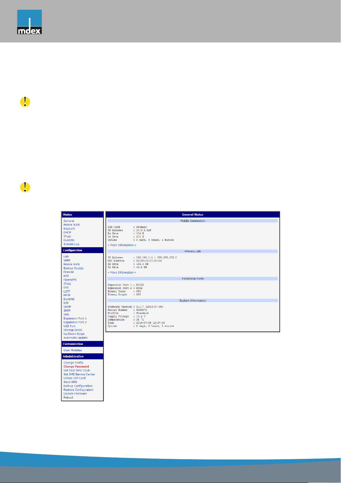
For monitoring, configuring and managing the router use web interface, which can be
invoked by entering the IP address of the router into your browser. The default IP address of
the router is 192.168.1.1. Configuration may be performed only by the user "root" with initial
password "root".
The left part of the web interface contains the menu with pages for monitoring (Status),
Configuration, Customization and Administration of the router.
Name and Location items displays the name and location of the router filled in the SNMP
configuration (see SNMP Configuration).
For increased safety of the network managed by the router must be changed the default
router password. If the router’s default password is set, the Change password item is highlighted in red.
Figure 1: Web configuration
1
Page 10

mdex AG • Bäckerbarg 6 • 22889 Tangstedt
1. CONFIGURATION OVER WEB
After green LED starts to blink it is possible to restore initial settings of the router by pressing button RST on front panel. If press button RST, configuration is restored to default and it
is reboot (green LED will be on).
1.1 Secured access to web configuration
To the web configuration can be accessed via a secure HTTPS protocol. In the event
of a default router IP address is a secure router configuration accessed by entering address
https://192.168.1.1 in the web browser. The first approach is the need to install a security certificate. If your browser reports a disagreement in the domain, this message can be prevented
use the following procedure.
Since the domain name in the certificate is given the MAC address of the router (such
separators are used dashes instead of colons), it is necessary to access the router under this
domain name. For access to the router via a domain name, it is adding a DNS record in the
DNS table, the operating system.
• Editing /etc/hosts (Linux/Unix)
• Editing C:\WINDOWS\system32\drivers\etc\hosts (Windows XP)
• Configuring your own DNS server
In addition to configuring the router with MAC address 00:11:22:33:44:55 is accessed to
secure configuration by typing address https://00-11-22-33-44-55 in the web browser. The first
approach is the need to install a security certificate.
When using self signing certificate must upload your files and https_cert https_key directory /etc/certs in the router.
1.2 General
A summary of basic information about the router and its activities can be invoked by selecting the General item. This page is also displayed when you login to the web interface.
Information is divided into a several of separate blocks according to the type of router activity or the properties area – Mobile Connection, Primary LAN, Peripherals Ports and System
Information. If your router is equipped with WIFI expansion port, there is also WIFI section.
1.2.1 Mobile Connection
Item Description
SIM Card Identification of the SIM card (Primary or Secondary)
Interface Defines the interface
Flags Displays network interface flags
IP Address IP address of the interface
Continued on next page
2
Page 11

mdex AG • Bäckerbarg 6 • 22889 Tangstedt
1. CONFIGURATION OVER WEB
Continued from previous page
Item Description
MTU Maximum packet size that the equipment is able to transmit
Rx Data Total number of received bytes
Rx Packets Received packets
Rx Errors Erroneous received packets
Rx Dropped Dropped received packets
Rx Overruns Lost received packets because of overload
Tx Data Total number of sent bytes
Tx Packets Sent packets
Tx Errors Erroneous sent packets
Tx Dropped Dropped sent packets
Tx Overruns Lost sent packets because of overload
Uptime Indicates how long the connection to mob. network is established
Table 1: Mobile connection
1.2.2 Primary LAN
Items displayed in this part have the same meaning as items in the previous part. Moreover,
there is information about the MAC address of the router (MAC Address item).
1.2.3 Peripheral Ports
Item Description
Expansion Port 1 Expansion port fitted to the position 1 (None indicates that this
position is equipped with no port)
Expansion Port 2 Expansion port fitted to the position 2 (None indicates that this
position is equipped with no port)
Binary Input State of binary input
Binary Output State of binary output
Table 2: Peripheral Ports
1.2.4 System Information
Item Description
Firmware Version Information about the firmware version
Serial Number Serial number of the router (in case of N/A is not available)
Continued on next page
3
Page 12

mdex AG • Bäckerbarg 6 • 22889 Tangstedt
1. CONFIGURATION OVER WEB
Continued from previous page
Item Description
Profile Current profile – standard or alternative profiles (profiles are used
for example to switch between different modes of operation)
Supply Voltage Supply voltage of the router
Temperature Temperature in the router
Time Current date and time
Uptime Indicates how long the router is used
Table 3: System Information
1.3 Mobile WAN status
This item is not available for mdex Router MX700.
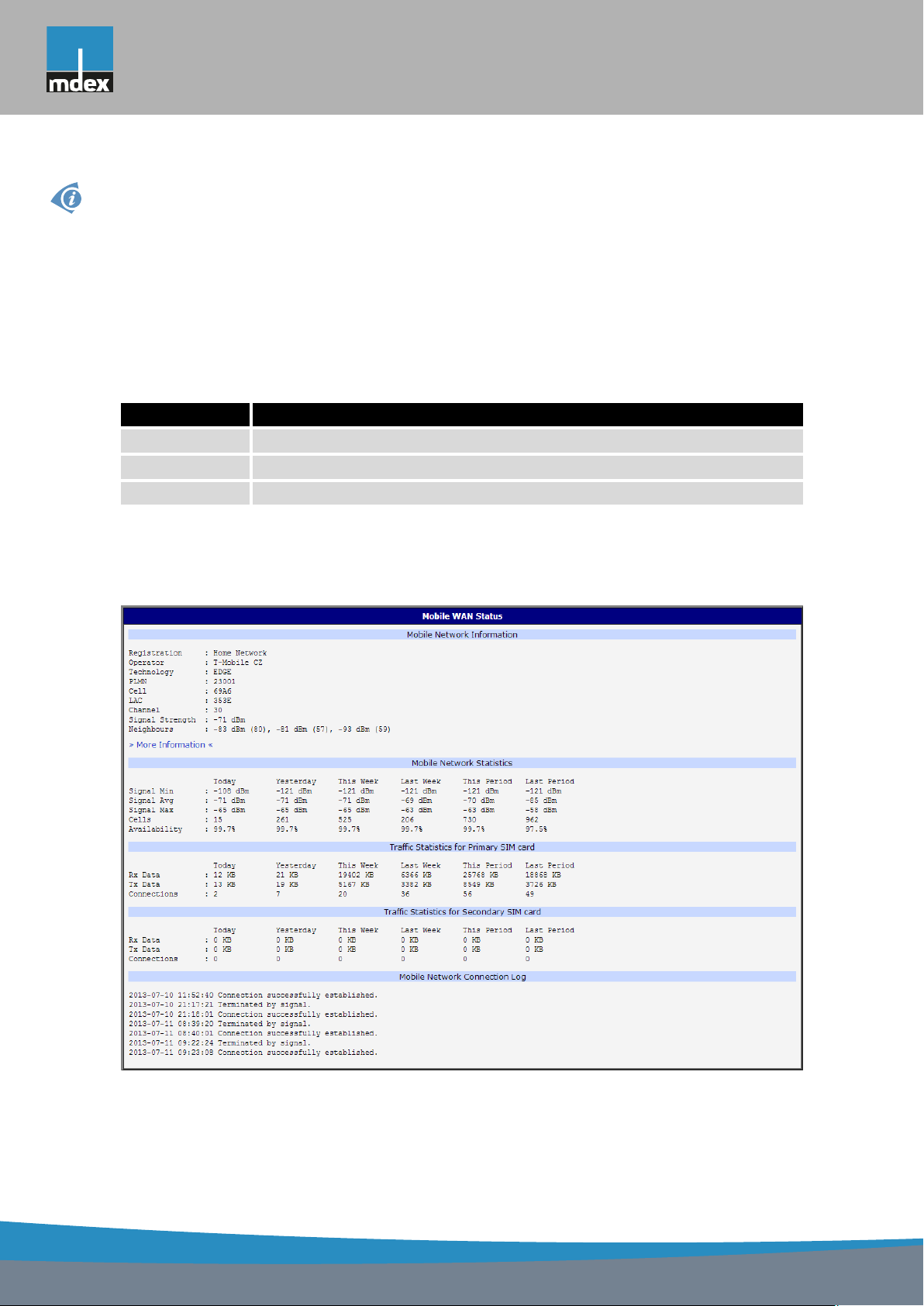
The Mobile WAN menu item contains current information about connections to the mobile
network. The first part of this page (Mobile Network Information) displays basic information
about mobile network in which the router is operated. There is also information about the
module, which is mounted in the router.
Item Description
Registration State of the network registration
Operator Specifies the operator in whose network the router is operated
Technology Transmission technology
PLMN Code of operator
Cell Cell to which the router is connected
LAC Location Area Code – unique number assigned to each location area
Channel Channel on which the router communicates
Signal Strength Signal strength of the selected cell
Signal Quality Signal quality of the selected cell:
• EC/IO for UMTS and CDMA (it’s the ratio of the signal received
from the pilot channel – EC – to the overall level of the spectral
density, ie the sum of the signals of other cells – IO)
• RSRQ for LTE technology (Defined as the ratio
• For EDGE technology (router MX720) value is not available
N ×RSRP
RSS I
)
Continued on next page
4
Page 13

mdex AG • Bäckerbarg 6 • 22889 Tangstedt
1. CONFIGURATION OVER WEB
Continued from previous page
Item Description
CSQ Cell Signal Quality, relative value is given by RSSI (dBm). 2–9 range
means Marginal, 10–14 range means OK, 15–16 range means Good,
20–30 range means excellent.
Neighbours Signal strength of neighboring hearing cells
Manufacturer Module manufacturer
Model Type of module
Revision Revision of module
IMEI IMEI (International Mobile Equipment Identity) number of module
ESN ESN (Electronic Serial Number) number of module (for CDMA routers)
MEID MEID number of module
ICCID Integrated Circuit Card Identifier is international and unique serial
number of the SIM card.
Table 4: Mobile Network Information
Highlighted in red adjacent cells have a close signal quality, which means that there is
imminence of frequent switching between the current and the highlighted cell.
The next section of this window displays information about the quality of the connection in
each period.
Period Description
Today Today from 0:00 to 23:59
Yesterday Yesterday from 0:00 to 23:59
This week This week from Monday 0:00 to Sunday 23:59
Last week Last week from Monday 0:00 to Sunday 23:59
This period This accounting period
Last period Last accounting period
Table 5: Description of period
Item Description
Signal Min Minimal signal strength
Signal Avg Average signal strength
Signal Max Maximal signal strength
Cells Number of switch between cells
Availability Availability of the router via the mobile network (expressed as a percent-
age)
Table 6: Mobile Network Statistics
5
Page 14
mdex AG • Bäckerbarg 6 • 22889 Tangstedt
1. CONFIGURATION OVER WEB
Tips for Mobile Network Statistics table:
• Availability is expressed as a percentage calculated by the ratio of time the connection
to mobile network was established to the time the router was turned on.
• After you place your cursor on the maximum or minimum signal strength, the last time
when the router reached this signal strength is displayed.
In the middle part of this page is displayed information about transferred data and number
of connections for both SIM card (for each period).
Item Description
RX data Total volume of received data
TX data Total volume of sent data
Connections Number of connection to mobile network establishment
Table 7: Traffic statistics
The last part (Mobile Network Connection Log) informs about the mobile network connec-
tion and problems in establishment.
Figure 2: Mobile WAN status
6
Page 15
mdex AG • Bäckerbarg 6 • 22889 Tangstedt
1. CONFIGURATION OVER WEB
1.4 WiFi
This item is available only if the router is equipped with a WiFi module.
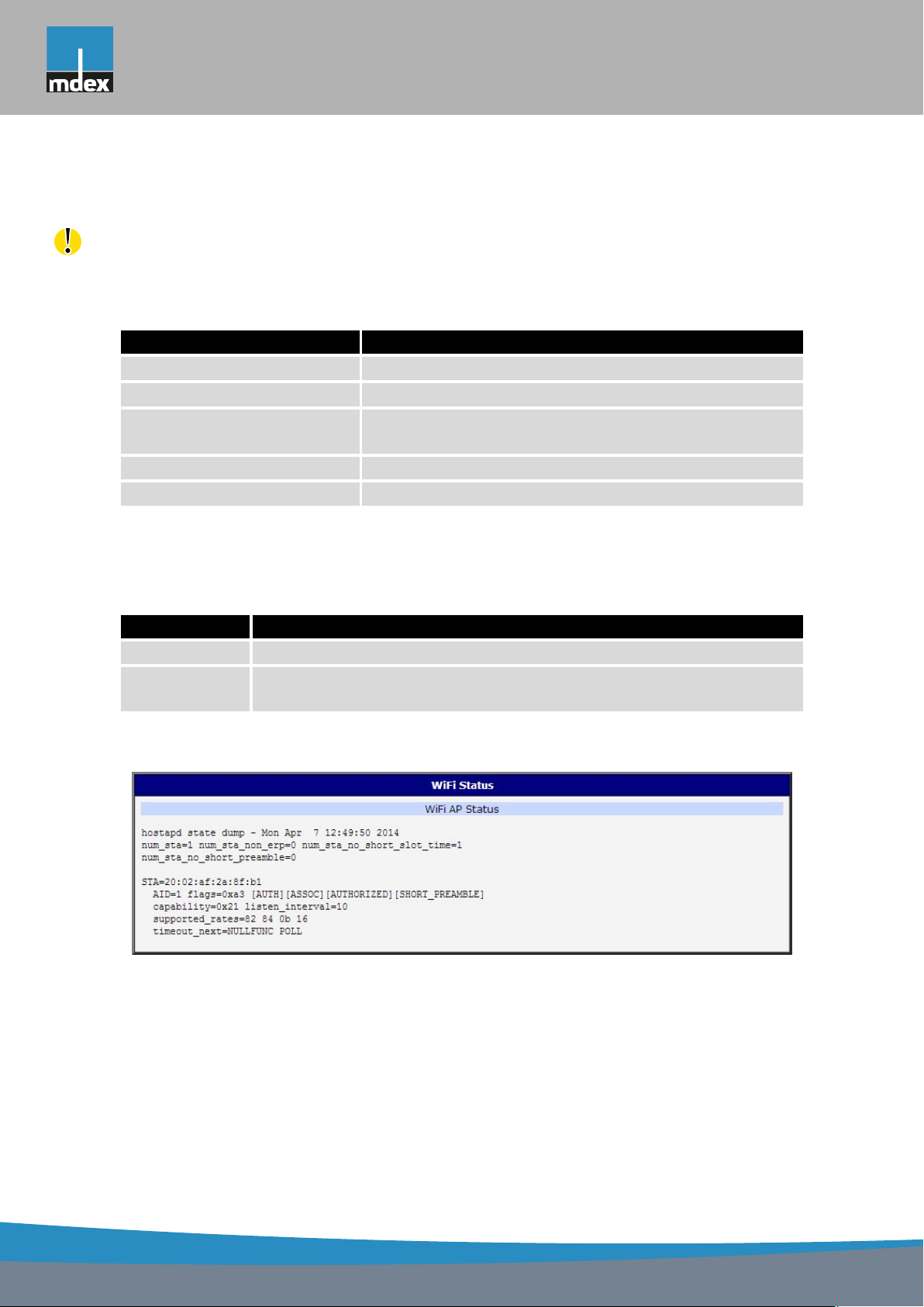
After selecting the WiFi item in the main menu of the web interface, information about WiFi
access point (AP) and associated stations is displayed.
Item Description
hostapd state dump Time to which statistical data relates
num_sta Number of connected stations
num_sta_non_erp Number of connected stations using 802.11b in 802.11g
BSS connection
num_sta_no_short_slot_time Number of stations not supporting the Short Slot Time
num_sta_no_short_preamble Number of stations not supporting the Short Preamble
Table 8: State information about access point
For each connected client are displayed more detailed information. Most of them has an
internal character, so let us mention only the following:
Item Description
STA MAC address of connected device (station)
AID Identifier of connected device (1 – 2007). If 0 is displayed, the station is
not currently connected.
Table 9: State information about connected clients
Figure 3: WiFi Status
7
Page 16

mdex AG • Bäckerbarg 6 • 22889 Tangstedt
1. CONFIGURATION OVER WEB
1.5 WiFi Scan
This item is available only if the router is equipped with a WiFi module.
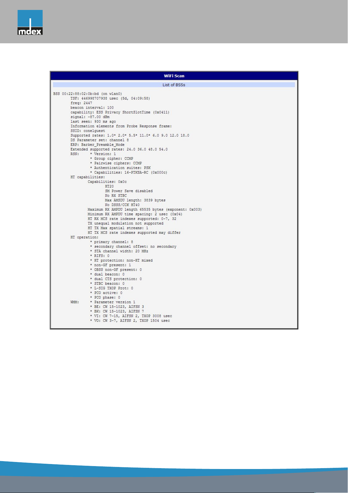
After selecting the WiFi Scan item in the menu of the web interface, scanning of neigh-
bouring WiFi networks and subsequent printing of results are invoked. Scanning can be per-
formed only if the access point (WiFi AP) is off.
item Description
BSS MAC address of access point (AP)
TSF A Timing Synchronization Function (TSF) keeps the timers for
all stations in the same Basic Service Set (BSS) synchronized.
All stations shall maintain a local TSF timer.
freq Frequency band of WiFi network [kHz]
beacon interval Period of time synchronization
capability List of access point (AP) properties
signal Signal level of access point (AP)
last seen Last response time of access point (AP)
SSID Identifier of access point (AP)
Supported rates Supported rates of access point (AP)
DS Parameter set The channel on which access point (AP) broadcasts
ERP Extended Rate PHY – information element providing backward
compatibility
Extended supported
rates
RSN Robust Secure Network – The protocol for establishing a se-
Supported rates of access point (AP) that are beyond the scope
of eight rates mentioned in Supported rates item
cure communication through wireless network 802.11
Table 10: Information about neighbouring WiFi networks
8
Page 17
mdex AG • Bäckerbarg 6 • 22889 Tangstedt
1. CONFIGURATION OVER WEB
Figure 4: WiFi Scan
9
Page 18

mdex AG • Bäckerbarg 6 • 22889 Tangstedt
1. CONFIGURATION OVER WEB
1.6 Network status
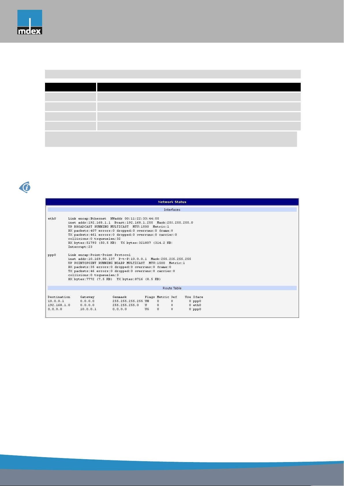
To view system information about the router operation, select the Network item in the main
menu. The upper part of the window displays detailed information about active interfaces:
Interface Description
eth0, eth1 Network interfaces (ethernet connection)
ppp0 Interface (active connection to GPRS/EDGE)
tun0 OpenVPN tunnel interface
ipsec0 IPSec tunnel interface
gre1 GRE tunnel interface
usb0 USB interface
Table 11: Description of interface in network status
By each of the interfaces is then shown the following information:
Item Description
HWaddr Hardware (unique) address of networks interface
inet IP address of interface
P-t-P IP address second ends connection
Bcast Broadcast address
Mask Mask of network
MTU Maximum packet size that the equipment is able to transmit
Metric Number of routers, over which packet must go trought
RX
TX
• packets – received packets
• errors – number of errors
• dropped – dropped packets
• overruns – incoming packets lost because of overload
• frame – wrong incoming packets because of incorrect packet size
• packets – transmit packets
• errors – number of errors
• dropped – dropped packets
• overruns – outgoing packets lost because of overload
• carrier – wrong outgoing packets with errors resulting from the
physical layer
Continued on next page
10
Page 19
mdex AG • Bäckerbarg 6 • 22889 Tangstedt
1. CONFIGURATION OVER WEB
Continued from previous page
Item Description
collisions Number of collisions on physical layer
txqueuelen Length of front network device
RX bytes Total number of received bytes
TX bytes Total number of transmitted bytes
Table 12: Description of information in network status
It is possible to read status of connection to mobile network from the network information.
If the connection to mobile network is active, then it is in the system information shown as a
ppp0 interface.
For mdex Router MX700, interface ppp0 indicates PPPoE connection.
Figure 5: Network status
11
Page 20
mdex AG • Bäckerbarg 6 • 22889 Tangstedt
1. CONFIGURATION OVER WEB
1.7 DHCP status
Information on the activities of the DHCP server can be accessed by selecting the DHCP
status item.
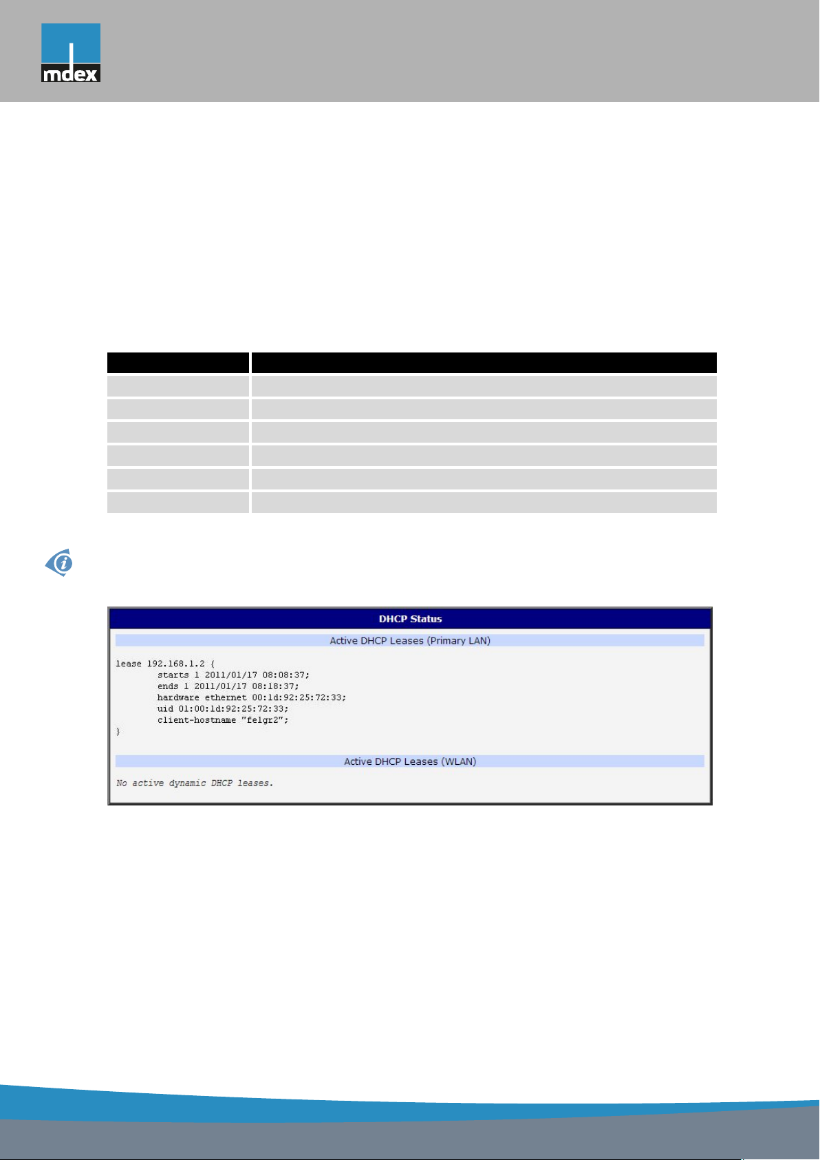
DHCP status informs about activities DHCP server. The DHCP server provides automatic
configuration of devices connected to the network managed router. DHCP server assigns to
each device’s IP address, netmask, default gateway (IP address of router) and DNS server (IP
address of router).
For each configuration, the DHCP status window displays the following information.
Item Description
lease Assigned IP address
starts Time of assignation of IP address
ends Time of termination IP address validity
hardware ethernet Hardware MAC (unique) address
uid Unique ID
client-hostname Computer name
Table 13: DHCP status description
In the extreme case, the DHCP status can display two records for one IP address. That
could have been caused by resetting of network cards.
Figure 6: DHCP status
Note: Starting with firmware 4.0.0, records in the DHCP status window are divided into two
separate parts – Active DHCP Leases (Primary LAN) and Active DHCP Leases (WLAN).
12
Page 21
mdex AG • Bäckerbarg 6 • 22889 Tangstedt
1. CONFIGURATION OVER WEB
1.8 IPsec status
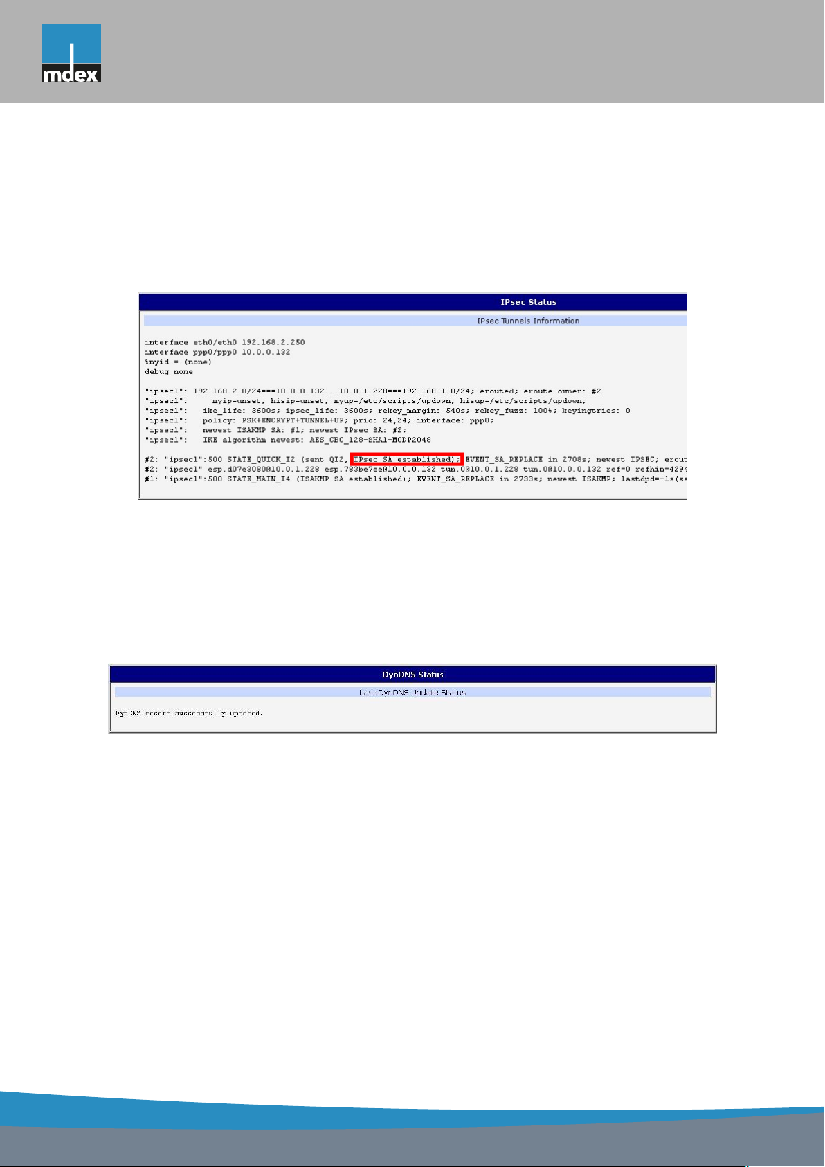
Information on actual IPsec tunnel state can be called up in option IPsec in the menu.
After correct build the IPsec tunnel, status display IPsec SA established (highlighted in
red) in IPsec status information. Other information is only internal character.
Figure 7: IPsec status
1.9 DynDNS status
The result of updating DynDNS record on the server www.dyndns.org can be invoked by
pressing the DynDNS item in the menu.
Figure 8: DynDNS status
13
Page 22

mdex AG • Bäckerbarg 6 • 22889 Tangstedt
1. CONFIGURATION OVER WEB
In detecting the status of updates DynDNS record are possible following message:
• DynDNS client is disabled.
• Invalid username or password.
• Specified hostname doesn?t exist.
• Invalid hostname format.
• Hostname exists, but not under specified username.
• No update performed yet.
• DynDNS record is already up to date.
• DynDNS record successfully update.
• DNS error encountered.
• DynDNS server failure.
For correct function DynDNS, SIM card of router must have assigned public IP address.
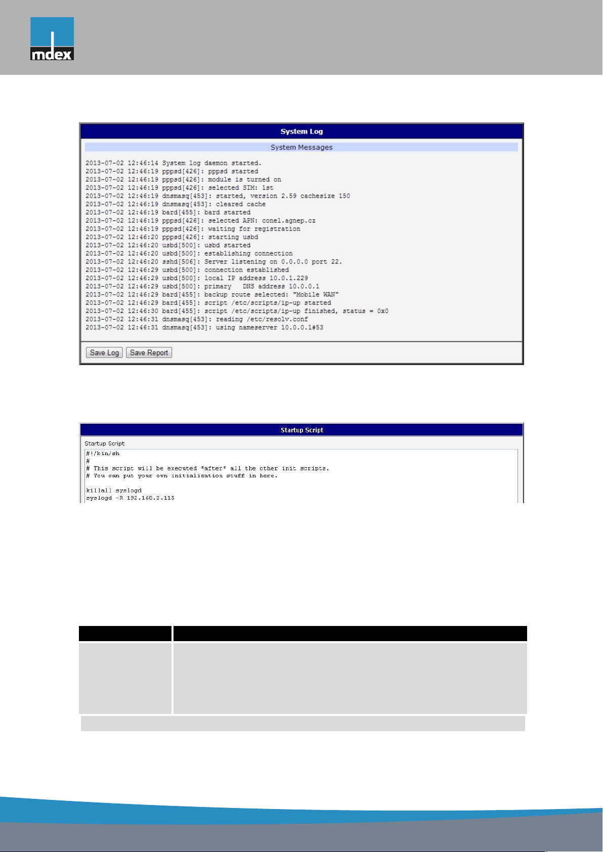
1.10 System Log
In case of any problems with connection to GPRS it is possible to view the system log
by pressing the System Log menu item. In the window, are displayed detailed reports from
individual applications running in the router. Use the Save Log button to save the system log
to a connected computer. The second button – Save Report – is used for creating detailed
report (generates all support needed information in one file).
The Syslog default size is 1000 lines. After reaching 1000 lines create a new file for storing
system log. After completion of the 1000 lines in the second file, the first file is deleted and
creates a new one.
Program syslogd can be started with two options that modifies its behavior. Option "-s"
followed by decimal number set maximal number of lines in one log file. Option "-r" followed
by hostname or IP address enable logging to remote syslog daemon. In the Linux must be
enabled remote logging on the target computer. Typically running syslogd with the parameter
?-r?. On Windows must be installed the syslog server (for example Syslog Watcher). For
starting syslogd with these options you could modify script "/etc/init.d/syslog" or add lines
"killall syslogd" and "syslogd <options> &" into Startup Script.
14
Page 23
mdex AG • Bäckerbarg 6 • 22889 Tangstedt
1. CONFIGURATION OVER WEB
Figure 9: System Log
Example of logging into the remote daemon at 192.168.2.115:
Figure 10: Example program syslogd start with the parameter -r
1.11 LAN configuration
To enter the network configuration, select the LAN menu item. ETH network set in Primary
LAN configuration, expansion PORT ETH set in Secondary LAN configuration.
Item Description
DHCP Client
• disabled – The router does not allow automatic allocation IP ad-
dress from a DHCP server in LAN network.
• enabled – The router allows automatic allocation IP address from
a DHCP server in LAN network.
Continued on next page
15
Page 24

mdex AG • Bäckerbarg 6 • 22889 Tangstedt
1. CONFIGURATION OVER WEB
Continued from previous page
Item Description
IP address Fixed set IP address of network interface ETH.
Subnet Mask IP address of Subnet Mask.
Bridged
• no – router is not used as a bridge (default)
• yes – router is used as a bridge
Media type
Default Gateway IP address of router default gateway. When entering IP address of
DNS server IP address of DNS server of router. Address where they are forwarded
Default Gateway and DNS Server items are used only if the DHCP Client item is set to a
value disabled and if the Primary or Secondary LAN is selected by Backup routes system as
a default route (selection algorithm is described in section 1.17 Backup Routes).
There can be only one active bridge on the router at the moment. Only parameters DHCP
Client, IP address and Subnet Mask can be used to configure bridge. Primary LAN has got
higher priority in this respect when both interfaces (eth0, eth1) are added to the bridge. Other
interfaces (wlan0 ? wifi) can be added (or deleted) to (from) existing bridge at any moment.
Moreover, the bridge can be created on demand of such interfaces but not configured by their
respective parameters.
DHCP server assigns IP address, gateway IP address (IP address of the router) and IP
address of the DNS server (IP address of the router) to the connected clients. If these values
are filled-in by the user in the configuration form, they are preferred.
DHCP server supports static and dynamic assignment of IP addresses. Dynamic DHCP
server assigns clients IP addresses from a defined address space. Static DHCP assigns IP
addresses that correspond to the MAC addresses of connected clients.
• Auto-negation – The router selects the speed of communication
of network options.
• 100 Mbps Full Duplex – The router communicates at 100Mbps,
in the full duplex mode.
• 100 Mbps Half Duplex – The router communicates at 100Mbps,
in the half duplex mode.
• 10 Mbps Full Duplex – The router communicates at 10Mbps, in
the full duplex mode.
• 10 Mbps Half Duplex – The router communicates at 10Mbps, in
the half duplex mode.
default gateway, all packets for which the record was not found in the
routing table, sent to this address.
to all DNS questions on the router.
Table 14: Configuration of network interface
16
Page 25
mdex AG • Bäckerbarg 6 • 22889 Tangstedt
1. CONFIGURATION OVER WEB
Item Description
Enable dynamic
DHCP leases
IP Pool Start Start IP addresses space to be allocated to the DHCP clients.
IP Pool End End IP addresses space to be allocated to the DHCP clients.
Lease time Time in seconds, after which the client can use IP address.
Item Description
Enable static
DHCP leases
MAC Address MAC address of a DHCP client.
IP Address Assigned IP address.
If this option is checked, dynamic DHCP server is enable.
Table 15: Configuration of dynamic DHCP server
If this option is checked, static DHCP server is enable.
Table 16: Configuration of static DHCP server
It is important not to overlap ranges of static allocated IP address with address allocated
by the dynamic DHCP. Then risk collision of IP addresses and incorrect function of network.
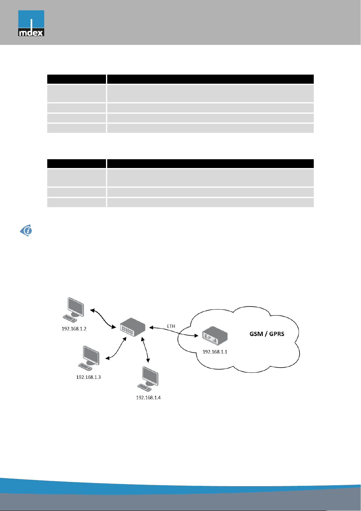
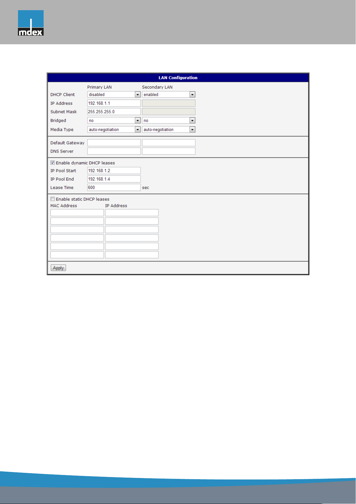
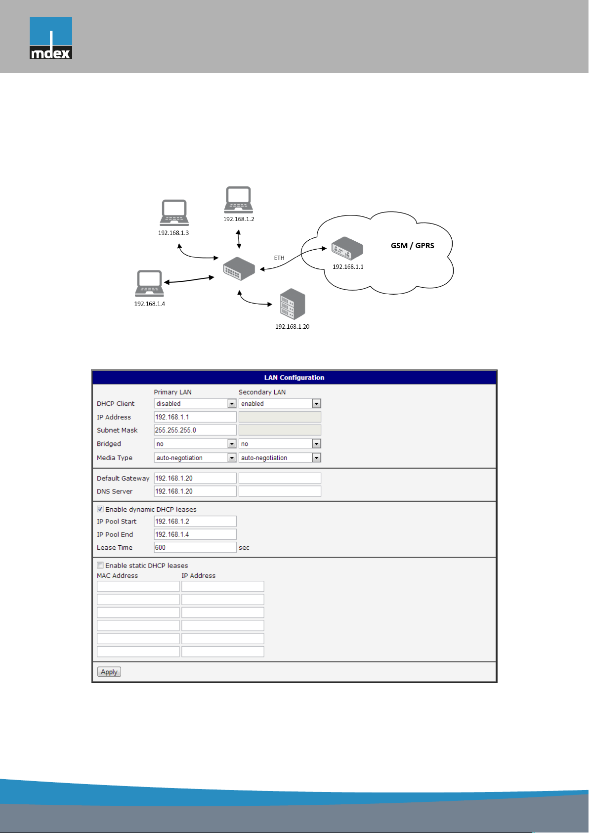
Example of the network interface with dynamic DHCP server:
• The range of dynamic allocated addresses from 192.168.1.2 to 192.168.1.4.
• The address is allocated 600 second (10 minutes).
Figure 11: Topology of example LAN configuration 1
17
Page 26
mdex AG • Bäckerbarg 6 • 22889 Tangstedt
1. CONFIGURATION OVER WEB
Figure 12: Example LAN configuration 1
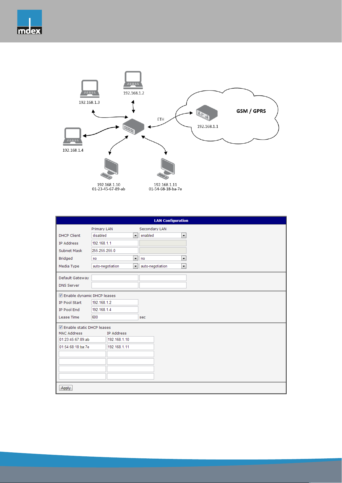
Example of the network interface with dynamic and static DHCP server:
• The range of allocated addresses from 192.168.1.2 to 192.168.1.4.
• The address is allocated 10 minutes.
• Client’s with MAC address 01:23:45:67:89:ab has IP address 192.168.1.10.
• Client’s with MAC address 01:54:68:18:ba:7e has IP address 192.168.1.11.
18
Page 27
mdex AG • Bäckerbarg 6 • 22889 Tangstedt
1. CONFIGURATION OVER WEB
Figure 13: Topology of example LAN configuration 2
Figure 14: Example LAN configuration 2
19
Page 28
mdex AG • Bäckerbarg 6 • 22889 Tangstedt
1. CONFIGURATION OVER WEB
Example of the network interface with default gateway and DNS server:
• Default gateway IP address is 192.168.1.20
• DNS server IP address is 192.168.1.20
Figure 15: Topology of example LAN configuration 3
Figure 16: Example LAN configuration 3
20
Page 29

mdex AG • Bäckerbarg 6 • 22889 Tangstedt
1. CONFIGURATION OVER WEB
1.12 VRRP configuration
To enter the VRRP configuration select the VRRP menu item. VRRP protocol (Virtual
Router Redundancy Protocol) is a technique, by which it is possible to forward routing from
main router to backup router in the case of the main router failure. If the Enable VRRP is
checked, then it is possible to set the following parameters.
Item Description
Virtual Server IP Address This parameter sets virtual server IP address. This address
should be the same for both routers. A connected device
sends its data via this virtual address.
Virtual Server ID Parameter Virtual Server ID distinguishes one virtual router
on the network from others. Main and backup routers must
use the same value for this parameter.
Host Priority The router, with higher priority set by the parameter Host
Priority, is the main router. According to RFC 2338 the main
router has the highest possible priority - 255. The backup
router has priority in range 1 ? 254 (init value is 100). The
priority value equals 0 is not allowed.
Table 17: VRRP configuration
It is possible to set Check connection flag in the second part of the window. The currently
active router (main/backup) will send testing messages to defined Ping IP Address at periodic
time intervals (Ping Interval) with setting time of waiting for answer (Ping Timeout). The function check connection is used as a supplement of VRRP standard with the same final result. If
there are no answers from remote devices (Ping IP Address) for a defined number of probes
(Ping Probes), then connection is switched to the other line.
Item Description
Ping IP Address Destinations IP address ping queries. Address can not specify as
domain name.
Ping Interval Time intervals between the outgoing pings.
Ping Timeout Time to wait to answer.
Ping Probes Number of failed ping requests, after which the route is considered
to be impassable.
Table 18: Check connection
Ping IP address is possible to use for example a DNS server of mobile operator as a test
message (ping) IP address.
There’s an additional way for evaluating the state of the active line. It is activated by
selecting Enable traffic monitoring parameter. If this parameter is set and any packet different
from ping is sent to the monitored line, then any answer to this packet is expected for Ping
21
Page 30
mdex AG • Bäckerbarg 6 • 22889 Tangstedt
1. CONFIGURATION OVER WEB
Timeout. If Ping Timeout expires with no answer received then process of testing the active
line continues the same way like in the case of standard testing process after first test message
answer drops out.
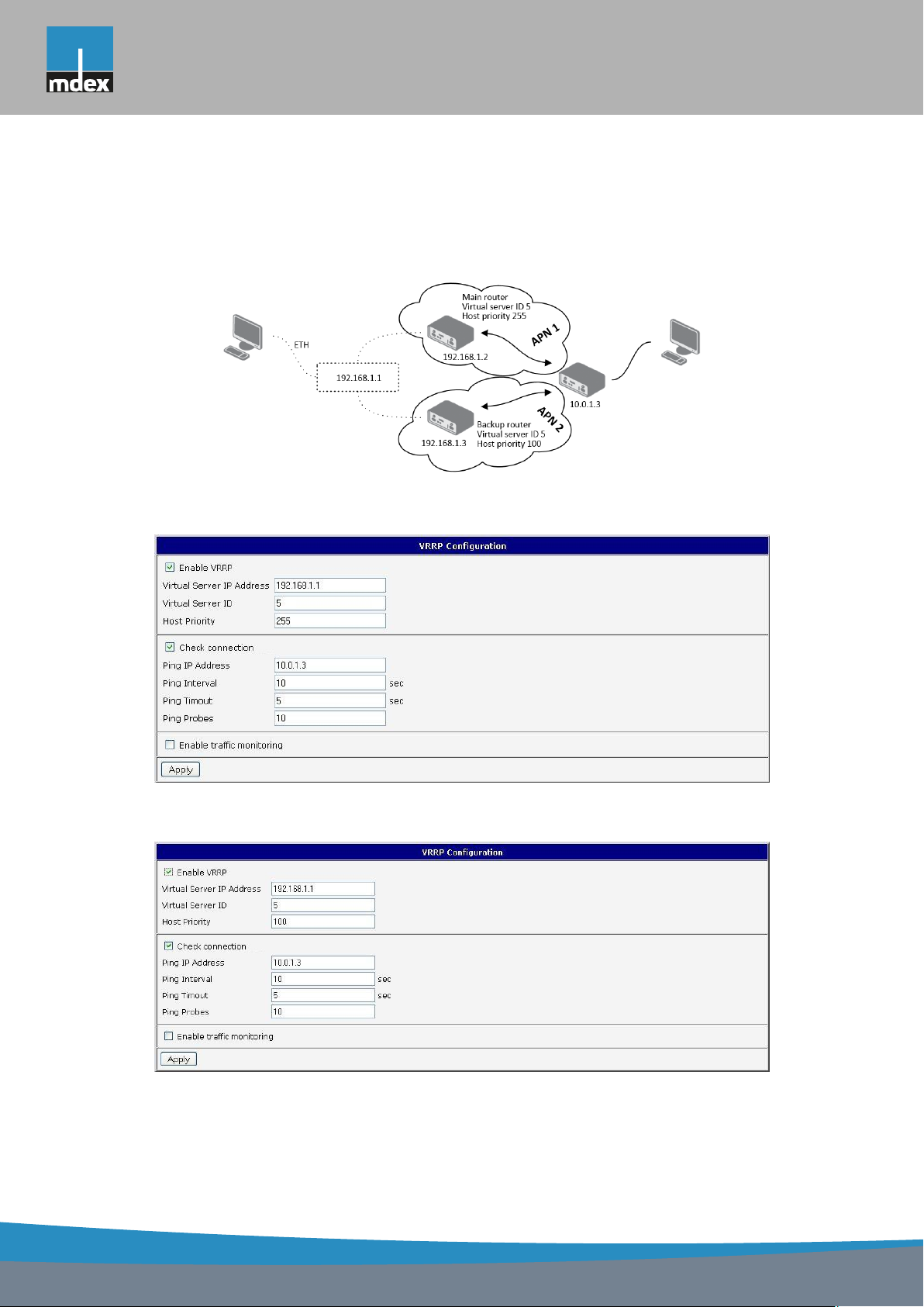
Example of the VRRP protocol:
Figure 17: Topology of example VRRP configuration
Figure 18: Example VRRP configuration ?- main router
Figure 19: Example VRRP configuration -? backup router
22
Page 31

mdex AG • Bäckerbarg 6 • 22889 Tangstedt
1. CONFIGURATION OVER WEB
1.13 Mobile WAN configuration
This item is not available for mdex Router MX700.
The form for configuration of a connection to the mobile network can be invoked by selecting the Mobile WAN item in the main menu of the router web interface.
1.13.1 Connection to mobile network
If the Create connection to mobile network item is selected, the router automatically tries
to establish connection after switching-on.
Item Description
APN Network identifier (Access Point Name)
Username User name to log into the GSM network
Password Password to log into the GSM network
Authentication Authentication protocol in GSM network:
• PAP or CHAP – authentication method is chosen by router
• PAP – it is used PAP authentication method
• CHAP – it is used CHAP authentication method
IP Address IP address of SIM card. The user sets the IP address, only in the case
IP address was assigned of the operator.
Phone Number Telephone number to dial GPRS or CSD connection. Router as a de-
fault telephone number used *99***1 #.
Operator This item can be defined PLNM preferred carrier code
Network type
PIN PIN parameter should be set only if it requires a SIM card router. SIM
MRU Maximum Receiving Unit – It’s an identifier of maximum size of packet,
MTU Maximum Transmission Unit – It’s an identifier of max. size of packet,
• Automatic selection – router automatically selects transmission
method according to the availability of transmission technology
• Furthermore, according to the type of router – it’s also possible to
select a specific method of data transmission (GPRS, UMTS, . . . )
card is blocked in case of several bad attempts to enter the PIN.
which is possible to receive in a given environment. Default value is
1500 B. Other settings may cause incorrect transmission of data.
which is possible to transfer in a given environment. Default value is
1500 B. Other settings may cause incorrect transmission of data.
Table 19: Mobile WAN connection configuration
23
Page 32

mdex AG • Bäckerbarg 6 • 22889 Tangstedt
1. CONFIGURATION OVER WEB
Tips for working with the Mobile WAN configuration form:
• If the size is set incorrectly, data transfer may not be succeeded. By setting a lower MTU
it occurs to more frequent fragmentation of data, which means higher overhead and also
the possibility of damage of packet during defragmentation. On the contrary, the higher
value of MTU can cause that the network does not transfer the packet.
• If the IP address field is not filled in, the operator automatically assigns the IP address
when it is establishing the connection. If filled IP address supplied by the operator, router
accelerate access to the network.
• If the APN field is not filled in, the router automatically selects the APN by the IMSI code
of the SIM card. If the PLMN (operator number format) is not in the list of APN, then
default APN is "internet". The mobile operator defines APN.
• If the word blank is filled in the APN field, router interprets APN as blank.
ATTENTION:
• If only one SIM card is plugged in the router (router has one slot for a SIM card),
router switches between the APN. Router with two SIM cards switches between
SIM cards.
• Correct PIN must be filled. For SIM cards with two APN?s there will be the same
PIN for both APN‘s. Otherwise the SIM card can be blocked by false SIM PIN.
Items marked with an asterisk must be filled in only if this information is required by the
operator (carrier).
In case of unsuccessful establishing a connection to mobile network is recommended to
check the accuracy of entered data. Alternatively, try a different authentication method or
network type.
1.13.2 DNS address configuration
The DNS Settings item is designed for easier configuration on the client side. When this
item is set to the value get from opertor router makes an attempt to automatically get an IP
address of the primary and secondary DNS server from the operator. By way of contrast, set
manually option allows you to set IP addresses of Primary DNS servers manually (using the
DNS Server item).
1.13.3 Check connection to mobile network configuration
If the Check Connection item is set to enabled or enabled + bind, checking the connection
to mobile network is activated. Router will automatically send ping requests to the specified
domain or IP address (Ping IP Address item) in regular time interval (Ping Interval). In case of
unsuccessful ping, a new one will be sent after ten seconds. If it fails to ping the IP address
of three times in a row, the router terminates the current connection and tries to establish new
24
Page 33

mdex AG • Bäckerbarg 6 • 22889 Tangstedt
1. CONFIGURATION OVER WEB
ones. Checking can be set separately for two SIM cards or two APNs. As a ping address can
be used an IP address for which it is certain that it is still functional and is possible to send
ICMP ping (e.g. DNS server of operator).
In the case of the enabled option ping requests are sent on the basis of routing table. Thus,
the requests may be sent through any available interface. If you require each ping request to
be sent through the network interface, which was created on the occasion of establishing a
connection to the mobile operator, it is necessary to set the Check Connection item to enabled
+ bind. The disabled variant deactivates checking the connection to mobile network.
Item Description
Ping IP Address Destinations IP address or domain name of ping queries.
Ping Interval Time intervals between the outgoing pings.
Table 20: Check connection to mobile network configuration
If the Enable Traffic Monitoring option is selected, then the router stops sending ping ques-
tions to the Ping IP Address and it will watch traffic in connection to mobile network. If this
connection is without traffic longer than the Ping Interval, then the router sends ping questions
to the Ping IP Address.
Attention! The feature of check connection to mobile network is necessary for uninterrupted operation.
1.13.4 Data limit configuration
Item Description
Data limit With this parameter you can set the maximum expected amount
of data transmitted (sent and received) over GPRS in one billing
period (month).
Warning Threshold Parameter Warning Threshold determine per cent of Data Limit in
the range of 50% to 99%, which if is exceeded, then the router
sends SMS in the form Router has exceeded (value of Warning
Threshold) of data limit.
Accounting Start Parameter sets the day of the month in which the billing cycle
starts SIM card used. Start of the billing period defines the operator, which gives the SIM card. The router begin to count the
transferred data since that day.
Table 21: Data limit configuration
If parameters Switch to backup SIM card when data limit is exceeded and switch to default
SIM card when data limit isn’t exceeded (see next subsection) or Send SMS when datalimit is
exceeded (see SMS configuration) are not selected the data limit will not count.
25
Page 34

mdex AG • Bäckerbarg 6 • 22889 Tangstedt
1. CONFIGURATION OVER WEB
1.13.5 Switch between SIM cards configuration
At the bottom of configuration it is possible to set rules for switching between two APN?s
on the SIM card, in the event that one SIM card is inserted or between two SIM cards, in the
event that two SIM cards are inserted.
Item Description
Default SIM card This parameter sets default APN or SIM card, from which it will try
to establish the connection to mobile network. If this parameter is
set to none, the router launches in offline mode and it is necessary
to establish connection to mobile network via SMS message.
Backup SIM card Defines backup APN or SIM card, that the router will switch the
defining one of the following rules.
Table 22: Default and backup SIM configuration
If parameter Backup SIM card is set to none, then parameters Switch to other SIM card
when connection fails, Switch to backup SIM card when roaming is detected and switch to
default SIM card when home network is detected and Switch to backup SIM card when data
limit is exceeded and switch to default SIM card when data limit isn’t exceeded switch the
router to off-line mode.
Item Description
Switch to other SIM card when
connection fails
Switch to backup SIM card when
roaming is detected and switch
to default SIM card when home
network is detected
Switch to backup SIM card when
data limit is exceeded and switch
to default SIM card when data
limit isn’t exceeded
If connection to mobile network fails, then this parameter ensures switch to secondary SIM card or secondary APN of the SIM card. Failure of the connection
to mobile network can occur in two ways. When I start
the router, when three fails to establish a connection
to mobile network. Or if it is checked Check the connection to mobile network, and is indicated by the loss
of a connection to mobile network.
In case that the roaming is detected this parameter enables switching to secondary SIM card or secondary
APN of the SIM. If home network is detected, this parameter enables switching back to default SIM card.
For proper operation, it is necessary to have enabled roaming on your SIM card!
This parameter enables switching to secondary SIM
card or secondary APN of the SIM card, when the data
limit of default APN is exceeded. This parameter also
enables switching back to default SIM card, when data
limit is not exceeded.
Continued on next page
26
Page 35

mdex AG • Bäckerbarg 6 • 22889 Tangstedt
1. CONFIGURATION OVER WEB
Continued from previous page
Item Description
Switch to backup SIM card when
binary input is active switch to
default SIM card when binary input isn’t active
Switch to default SIM card after
timeout
Table 23: Switch between SIM card configurations
The following parameters define the time after which the router attempts to go back to the
default SIM card or APN.
This parameter enables switching to secondary SIM
card or secondary APN of the SIM card, when binary
input ?bin0? is active. If binary input isn’t active, this
parameter enables switching back to default SIM card.
This parameter defines the method, how the router will
try to switch back to default SIM card or default APN.
Item Description
Initial timeout The first attempt to switch back to the primary SIM card or APN
shall be made for the time defined in the parameter Initial Timeout, range of this parameter is from 1 to 10000 minutes.
Subsequent Timeout In an unsuccessful attempt to switch to default SIM card, the
router on the second attempt to try for the time defined in the
parameter Subsequent Timeout, range is from 1 to 10000 min.
Additive constants Any further attempt to switch back to the primary SIM card or APN
shall be made in time computed as the sum of the previous time
trial and time defined in the parameter Additive constants range
is 1-10000 minutes.
Table 24: Switch between SIM card configurations
Example:
If parameter Switch to default SIM card after timeout is checked and parameters are set as
follows: Initial Timeout ? 60 min, Subsequent Timeout 30 min and Additive Timeout ? 20 min,
the first attempt to switch the primary SIM card or APN shall be carried out after 60 minutes.
Switched to a failed second attempt made after 30 minutes. Third after 50 minutes (30+20).
Fourth after 70 minutes (30+20+20).
27
Page 36

mdex AG • Bäckerbarg 6 • 22889 Tangstedt
1. CONFIGURATION OVER WEB
1.13.6 Dial-In access configuration
Dial-In access configuration is supported only for these routers: MX720 and MX740.
In the bottom part of the window it is possible to define access over CSD connection by
Enable Dial-In Access function. Access can be secured by used the Username and Password. In the event that this function is enabled and the router does not have a connection to
mobile network is granted access to the router via dial-up connections CSD. The router waits
2 minutes to accept connections. If the router during this time nobody logs on, the router will
try again to establish a GPRS connection.
Item Description
Username User name for secured Dial-In access.
Password Password for secured Dial-In access.
Table 25: Dial-In access configuration
1.13.7 PPPoE bridge mode configuration
If the Enable PPPoE bridge mode option selected, it activate the PPPoE bridge protocol
PPPoE (point-to-point over ethernet) is a network protocol for encapsulating Point-to-Point
Protocol (PPP) frames inside Ethernet frames. Allows you to create a PPPoE connection from
the device behind router. For example from PC which is connected to ETH port router. There
will be allot Ip address of SIM card to PC.
The changes in settings will apply after pressing the Apply button.
28
Page 37
mdex AG • Bäckerbarg 6 • 22889 Tangstedt
1. CONFIGURATION OVER WEB
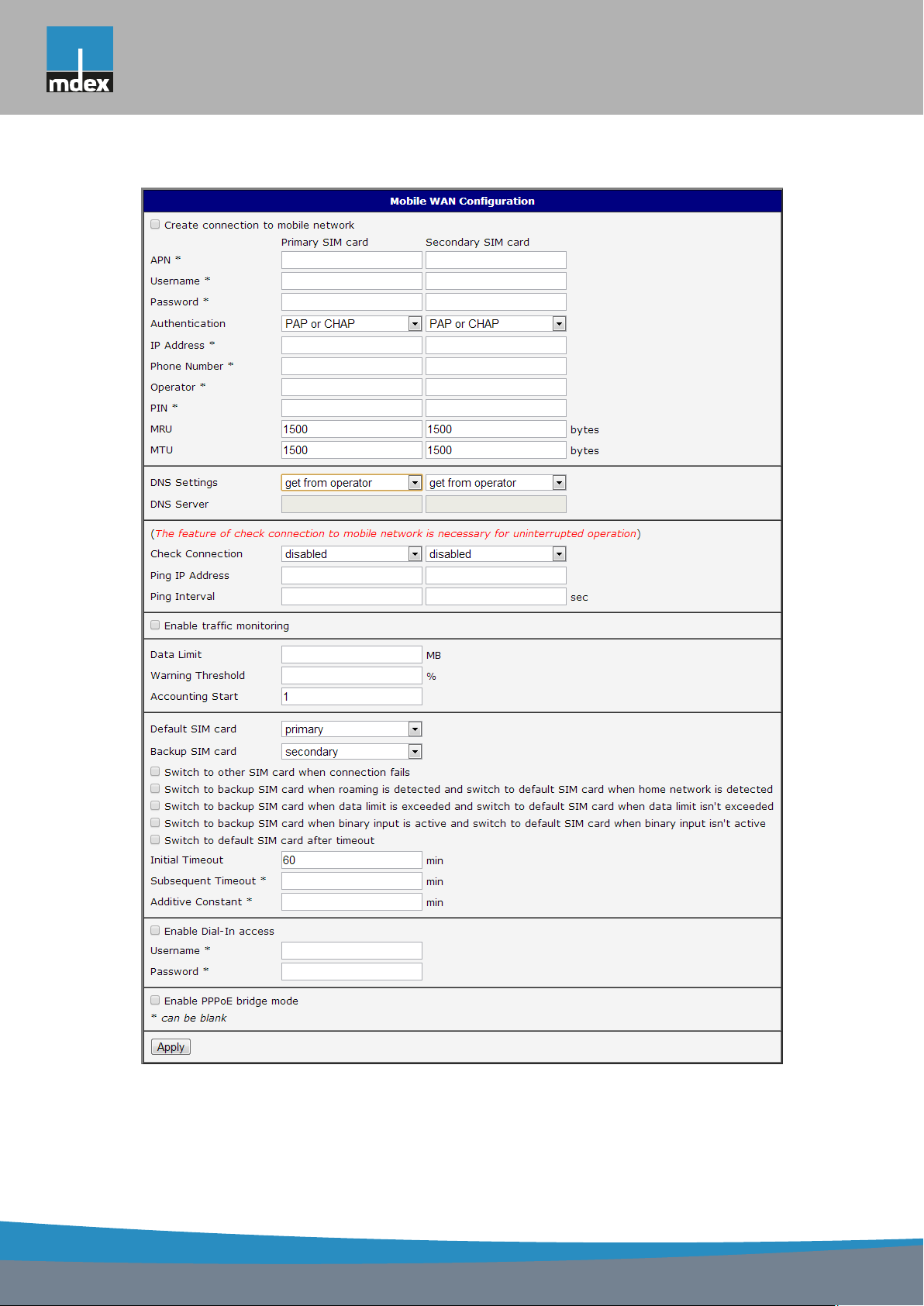
Figure 20: Mobile WAN configuration
29
Page 38
mdex AG • Bäckerbarg 6 • 22889 Tangstedt
1. CONFIGURATION OVER WEB
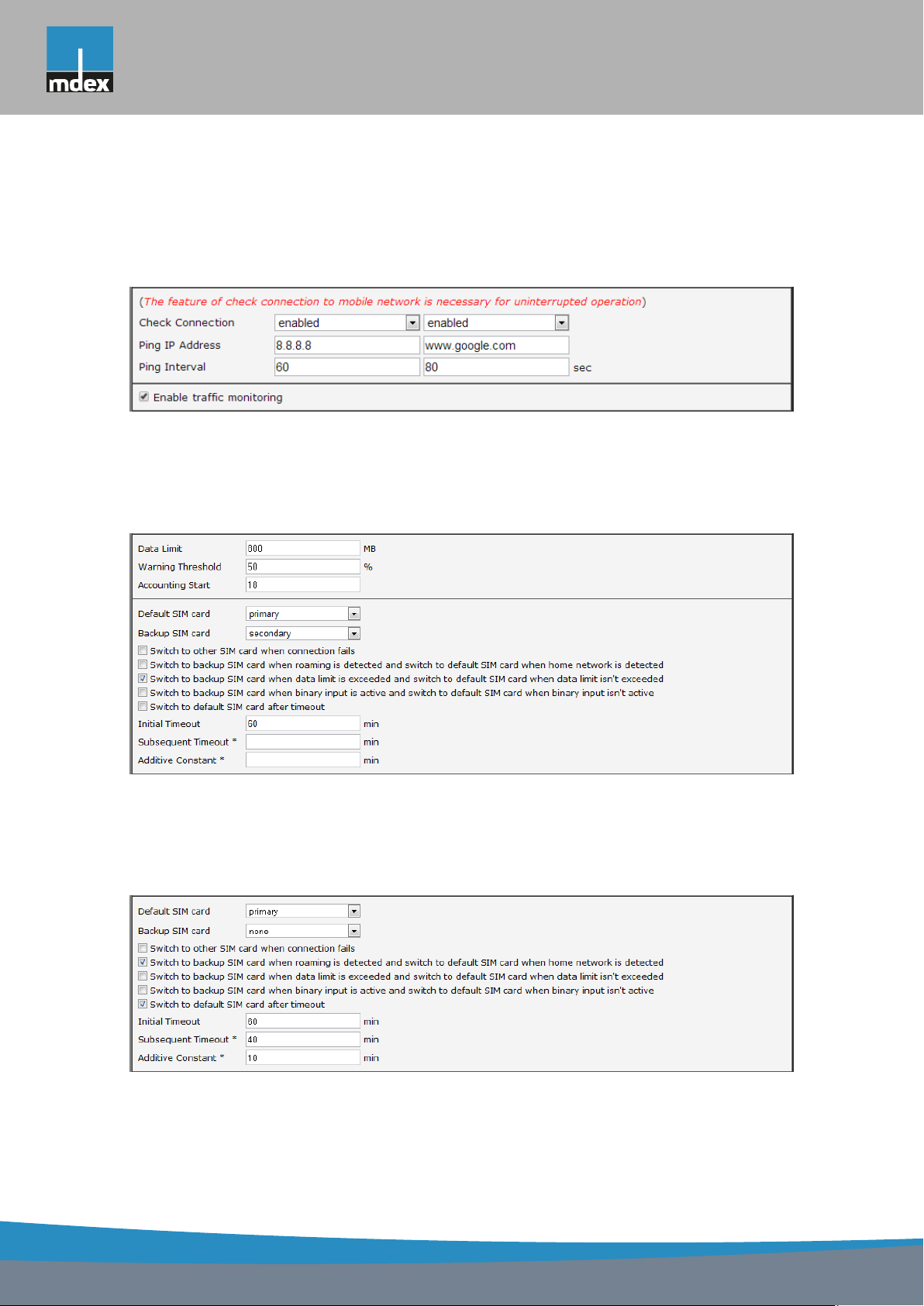
The figure below describes the situation, when the connection to mobile network is controlled on the address 8.8.8.8 in the time interval of 60 s for primary SIM card and on the
address www.google.com in the time interval 80 s for secondary SIM card. In the case of
traffic on the router the control pings are not sent, but the traffic is monitored.
Figure 21: Example of Mobile WAN configuration 1
The following configuration illustrates the situation in which the router switches to a backup
SIM card after exceeding the data limits of 800 MB. Warning SMS is sent upon reaching 400
MB. The start of accounting period is set to the 18th day of the month.
Figure 22: Example of Mobile WAN configuration 2
Primary SIM card is switched to the offline mode after the router detects roaming. The first
attempt to switch back to the default SIM card is executed after 60 minutes, the second after
40 minutes, the third after 50 minutes (40+10) etc.
Figure 23: Example of Mobile WAN configuration 3
30
Page 39
mdex AG • Bäckerbarg 6 • 22889 Tangstedt
1. CONFIGURATION OVER WEB
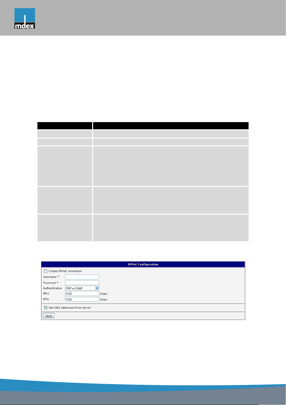
1.14 PPPoE Configuration
To enter the PPPoE configuration select the PPPoE menu item. If the Create PPPoE connection option is selected, the router tries to establish PPPoE connection after switching-on.
PPPoE (Point-to-Point over Ethernet) is a network protocol, which PPP frames encapsulating to the Ethernet frames. PPPoE client to connect devices that support PPPoE bridge or
a server (typically ADSL router). After connecting the router obtains the IP address of the
device to which it is connected. All communications from the device behind the PPPoE server
is forwarded to industrial router.
Item Description
Username Username for secure access to PPPoE
Password Password for secure access to PPPoE
Authentication Authentication protocol in GSM network
• PAP or CHAP – authentication method is chosen by router
• PAP – it is used PAP authentication method
• CHAP – it is used CHAP authentication method
MRU Maximum Receiving Unit – It is the identifier of the maximum size
of packet, which is possible to recese in given environment. Default value is set to 1492 bytes. Other settings may cause incorrect data transmission.
MTU Maximum Transmission Unit – It is the identifier of the maximum
size of packet, which is possible to transfer in given environment.
Default value is set to 1492 bytes. Other settings may cause incorrect data transmission.
Table 26: PPPoE configuration
Figure 24: PPPoE configuration
31
Page 40

mdex AG • Bäckerbarg 6 • 22889 Tangstedt
1. CONFIGURATION OVER WEB
1.15 WiFi configuration
This item is available only if the router is equipped with a WiFi module.
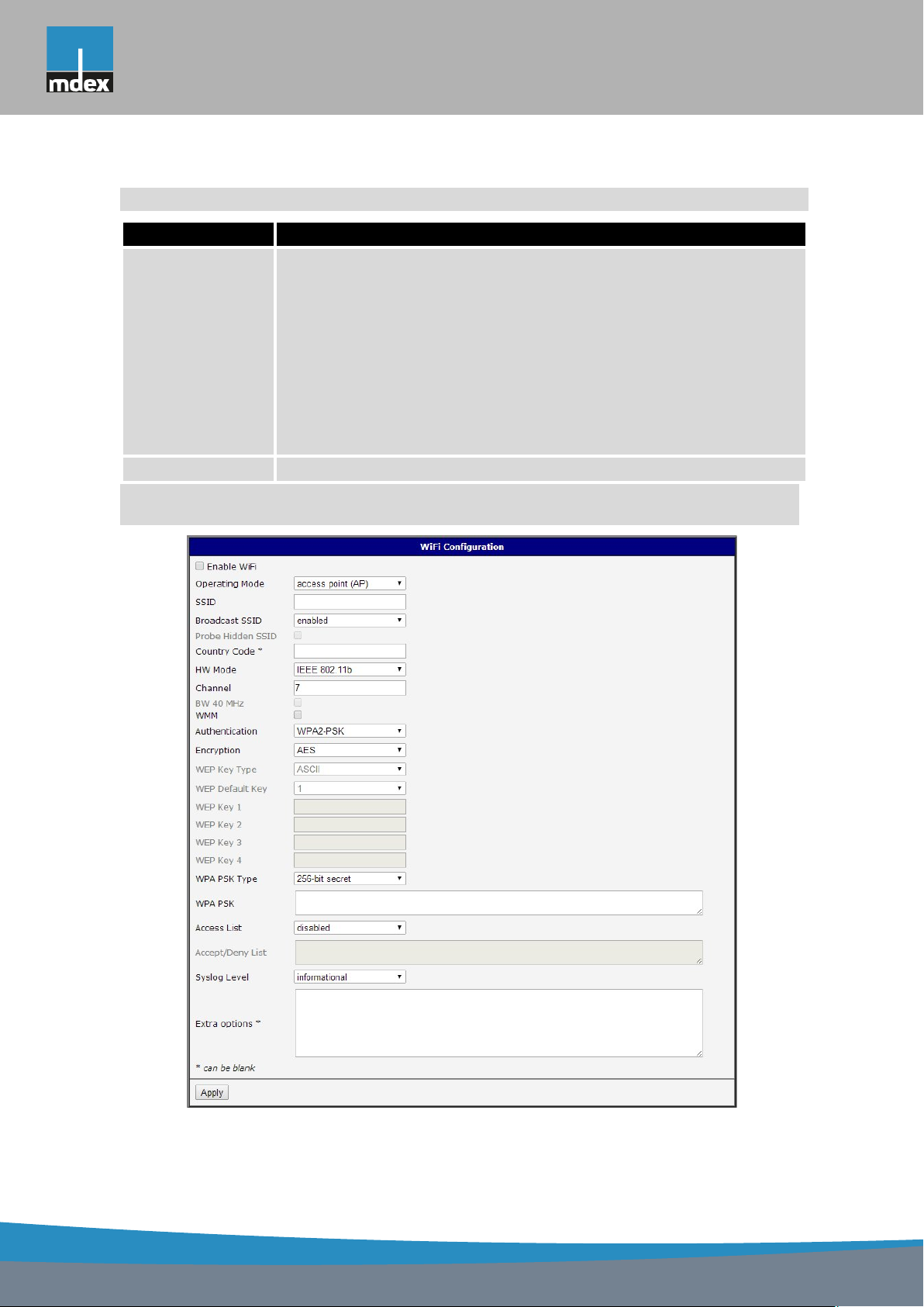
The form for configuration of WiFi network can be invoked by pressing the WiFi item in the
main menu of the router web interface. Enable WiFi check box at the top of this form is used
to activate WiFi. It is also possible to set the following properties:
Item Description
Operating mode WiFi operating mode:
• access point (AP) – router becomes an access point to which
other devices in station (STA) mode can be connected
• station (STA) – router becomes a client station, it means that
receives data packets from the available access point (AP) and
sends data from cable connection via wifi network
SSID Unique identifier of WiFi network
Broadcast SSID Method of broadcasting the unique identifier of SSID network in bea-
con frame and type of response to a request for sending the beacon
frame.
• Enabled – SSID is broadcasted in beacon frame
• Zero length – Beacon frame does not include SSID. Requests
for sending beacon frame are ignored.
• Clear – Each SSID character in beacon frame is replaced by 0.
However, original length is kept. Requests for sending beacon
frame are ignored.
Probe Hidden
SSID
Country Code Code of the country, where the router is used with WiFi. This code
Probes hidden SSID (only for station (STA) mode)
must be entered in format ISO 3166-1 alpha-2. If country code isn?t
specified and the router has implemented no system to determine
this code, it is used "US" as default country code.
If no country code is specified or is entered the wrong country code,
then it may come a pass a breach of regulatory rules for the using of
frequency bands in the particular country.
Continued on next page
32
Page 41

mdex AG • Bäckerbarg 6 • 22889 Tangstedt
1. CONFIGURATION OVER WEB
Continued from previous page
Item Description
HW Mode HW mode of WiFi standard that will be supported by WiFi access
point (AP).
• IEE 802.11b
• IEE 802.11b+g
• IEE 802.11b+g+n
Channel Channel where the WiFi AP is transmitting
BW 40 MHz Option for HW mode 802.11n that allows using of two standard
20 MHz channels simultaneously.
WMM Enables basic QoS for WiFi networks. This version doesn?t guaran-
tee network throughput. It is suitable for simple applications requiring
QoS.
Authentication Provides access control of authorized users in WiFi network:
• Open – authentication is not required (free access point)
• Shared – base authentication using WEP key
• WPA-PSK – authentication using better authentication method
PSK-PSK
• WPA2-PSK – authentication using AES encryption
Encryption Type of data encryption in WiFi network:
• None – No data encryption
• WEP – Encryption using static WEP keys. This encryption can
be used for Shared authentication.
• TKIP – Dynamic management of encryption keys which can be
used for WPA-PSK and WPA2-PSK authentication.
• AES – Improved encryption used for WPA2-PSK authentication
WEP Key Type Type of WEP key for WEP encryption:
• ASCII – WEP key is entered in ASCII format
• HEX – WEP key is entered in hexadecimal format
WEP Default Key Specifies default WEP key
Continued on next page
33
Page 42

mdex AG • Bäckerbarg 6 • 22889 Tangstedt
1. CONFIGURATION OVER WEB
Continued from previous page
Item Description
WEP Key 1-4 Items for different four WEP keys
• WEP key in ASCII format must be entered in quotes and must
have the following lengths:
– 5 ASCII characters (40b WEP key)
– 13 ASCII characters (104b WEP key)
– 16 ASCII characters (128b WEP key)
• WEP key in hexadecimal format must be entered using only
hexadecimal digits and must the following lengths:
– 10 hexadecimal digits (40b WEP key)
– 26 hexadecimal digits (104b WEP key)
– 32 hexadecimal digits (128b WEP key)
WPA PSK Type The type of encryption when WPA-PSK authenticating:
• 256-bit secret
• ASCII passphrase
• PSK File
WPA PSK Key for WPA-PSK authentication. This key must be entered accord-
ing to the selected WPA-PSK type as follows:
• 256-bit secret – 64 hexadecimal digits
• ASCII passphrase – from 8 to 63 characterswhich are subse-
quently converted into PSK
• PSK File – absolute path to the file containing the list of pairs
(PSK key, MAC address)
Access List Determines a manner of Access/Deny list application:
• Disabled – Access/Deny list is not used
• Accept – Only items mentioned in the Access/Deny list have
access to the network
• Deny – Items mentioned in the Access/Deny list do not have
access to the network
Accept/Deny List Accept or Denny list of client MAC addresses that set network ac-
cess. Each MAC address is separated by new line.
Continued on next page
34
Page 43
mdex AG • Bäckerbarg 6 • 22889 Tangstedt
1. CONFIGURATION OVER WEB
Continued from previous page
Item Description
Syslog Level Communicativeness level when system writes to the system log
• Verbose debugging – the highest level of communicativeness
• Debugging
• Informational – default level of communicativeness which is
used for writing standard events
• Notification
• Warning – the lowest level of communicativeness
Extra options Allows user to define additional parameters
Table 27: WiFi configuration
Figure 25: WiFi konfigurace
35
Page 44

mdex AG • Bäckerbarg 6 • 22889 Tangstedt
1. CONFIGURATION OVER WEB
1.16 WLAN configuration
This item is available only if the router is equipped with a WiFi module.
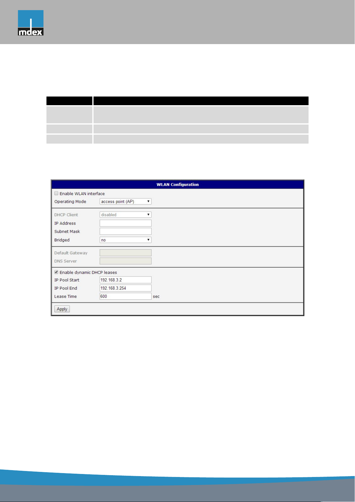
The form for configuration of WiFi network and DHCP server functioning on this network
can be invoked by pressing the WLAN item in the main menu of the router web interface.
Enable WLAN interface check box at the top of this form is used to activate WIFi LAN interface.
It is also possible to set the following properties:
Item description
Operating Mode WiFi operating mode:
• access point (AP) – router becomes an access point to
which other devices in station (STA) mode can be connected
• station (STA) – router becomes a client station, it means
that receives data packets from the available access point
(AP) and sends data from cable connection via wifi network
DHCP Client Activates/deactivates DHCP client
IP Address Fixed set IP address of WiFi network interface
Subnet Mask Subnet mask of WiFi network interface
Bridged Activates bridge mode:
• no – Bridged mode is not allowed (it’s default value). WLAN
network is not connected with LAN network of the router.
• yes – Bridged mode is allowed. WLAN network is connected
with one or more LAN network of the router. In this case, the
setting of most items in this table is ignored. Instead, it takes
setting of selected network interface (LAN).
Default Gateway IP address of default gateway. When entering IP address of de-
fault gateway, all packets for which the record was not found in the
routing table are sent to this address.
DNS Server Address to which all DNS queries are forwarded
Table 28: WLAN configuration
36
Page 45
mdex AG • Bäckerbarg 6 • 22889 Tangstedt
1. CONFIGURATION OVER WEB
Use Enable dynamic DHCP leases item at the bottom of this form to enable dynamic
allocation of IP addresses using DHCP server. It is also possible to specify these values:
Item Description
IP Pool Start Beginning of the range of IP addresses which will be assigned to DHCP
clients
IP Pool End End of the range of IP addresses which will be assigned to DHCP clients
Lease Time Time in seconds for which the client may use the IP address
Table 29: Configuration of DHCP server
All changes in settings will apply after pressing the Apply button.
Figure 26: WLAN configuration
37
Page 46
mdex AG • Bäckerbarg 6 • 22889 Tangstedt
1. CONFIGURATION OVER WEB
1.17 Backup Routes
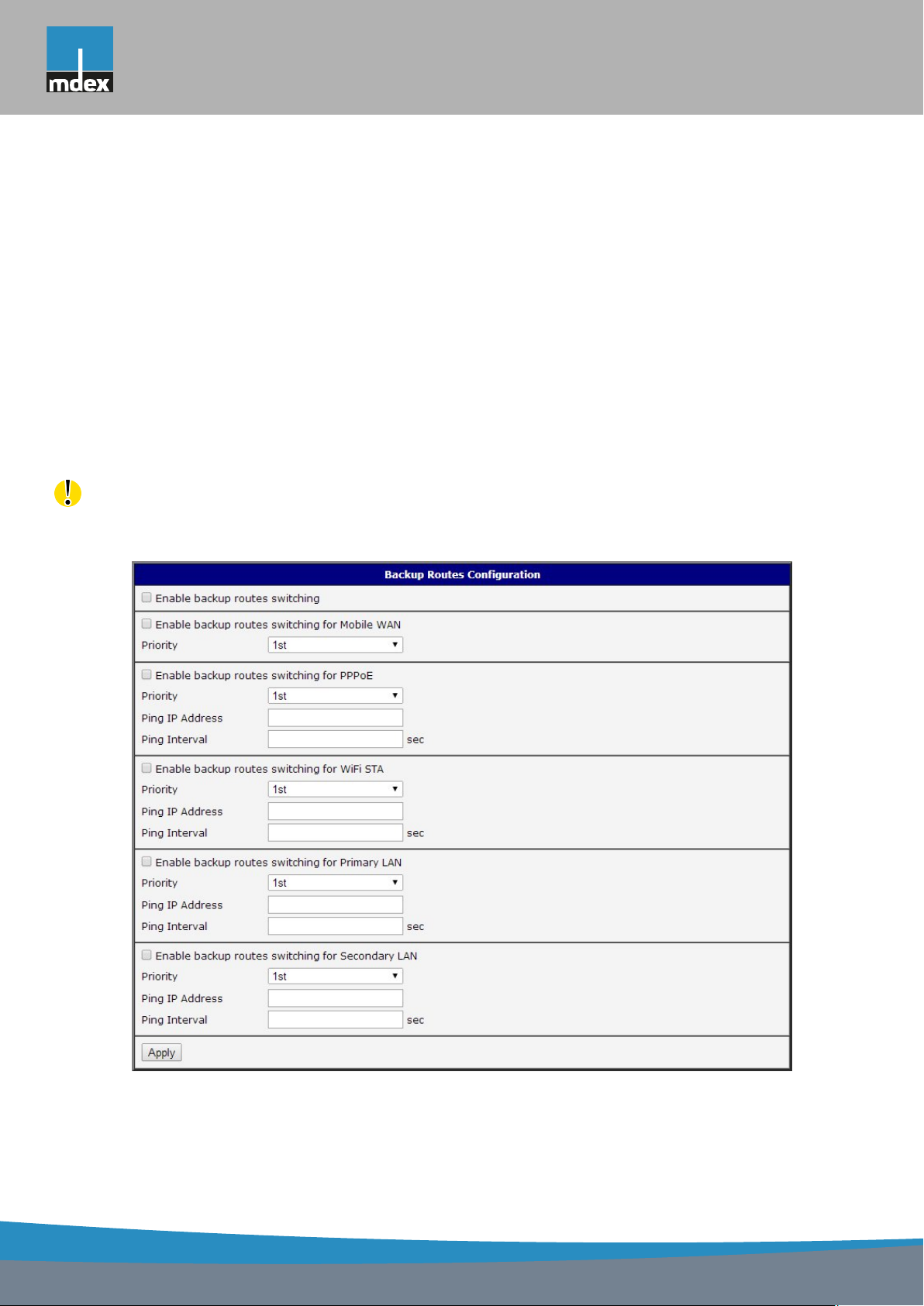
Using the configuration form on the Backup Routes page can be set backing up primary
connection by other connections to internet/mobile network. For each back up connection can
be defined a priority. Own switching is done based on set priorities and state of the connection
(for Primary LAN and Secondary LAN).
If Enable backup routes switching option is checked, the default route is selected accord-
ing to the settings below. Namely according to status of enabling each of backup route (i.e.
Enable backup routes switching for Mobile WAN, Enable backup routes switching for PPPoE,
Enable backup routes switching for WiFi STA, Enable backup routes switching for Primary
LAN or Enable backup routes switching for Secondary LAN), according to explicitly set pri-
orities and according to status of connection check (if it is enabled). In addition, network
interfaces belonging to individual backup routes have checked a flag RUNNING. This check
fixes for example disconnecting of an ethernet cable.
Attention! If you want to use connection to mobile WAN as one of the backup routes, it is
necessary to enable Check Connection at Mobile WAN configuration to enable + bind option,
see chapter 1.13.3.
Figure 27: Backup Routes
38
Page 47

mdex AG • Bäckerbarg 6 • 22889 Tangstedt
1. CONFIGURATION OVER WEB
If Enable backup routes switching option is not checked, Backup routes system operates
in the so-called backward compatibility mode. The default route is selected based on implicit
priorities according to the status of enabling settings for each of network interface, as the case
may be enabling services that set these network interfaces. Names of backup routes and
corresponding network interfaces in order of implicit priorities:
• Mobile WAN (pppX, usbX)
• PPPoE (ppp0)
• Secondary LAN (eth1)
• Primary LAN (eth0)
Example:
Secondary LAN is selected as the default route only if Create connection to mobile network
option is not checked on the Mobile WAN page, alternatively if Create PPPoE connection
option is not checked on the PPPoE page. To select the Primary LAN it is also necessary
not to be entered IP address for Secondary LAN and must not be enabled DHCP Client for
Secondary LAN.
Item Description
Priority Priority for the type of connection
Ping IP Address Destination IP address of ping queries to check the connection
(address can not be specified as a domain name)
Ping Interval The time intervals between sent ping queries
Table 30: Backup Routes
All changes in settings will be applied after pressing the Apply button.
1.18 Firewall configuration
The first security element which incoming packets must pass is check of enabled source IP
addresses and destination ports. It can be specified IP addresses from which you can remotely
access the router and the internal network connected behind a router. If the Enable filtering of
incoming packets item is checked (located at the beginning of the configuration form Firewall),
this element is enabled and accessibility is checked against the table with IP addresses. This
means that access is permitted only addresses specified in the table. It is possible to define
up to eight remote accesses. There are the following parameters:
39
Page 48

mdex AG • Bäckerbarg 6 • 22889 Tangstedt
1. CONFIGURATION OVER WEB
Item Description
Source IP address from which access to the router is allowed
Protocol Specifies protocol for remote access:
• all – access is enabled for all protocols
• TCP – access is enabled for TCP protocol
• UDP – access is enabled for UDP protocol
• ICMP – access is enabled for ICMP protocol
Target Port The port number on which access to the router is allowed
Action Type of action:
• allow – access is allowed
• deny – access is denied
Table 31: Filtering of incoming packets
The following part of the configuration form defines the forwarding policy. If Enabled filter-
ing of forwarded packets item is not checked, packets are automatically accepted. If this item
is checked and incoming packet is addressed to another network interface, it will go to the
FORWARD chain. In case that the FORWARD chain accepted this packet (there is a rule for
its forwarding), it will be sent out. If the forwarding rule does not exist, packet will be dropped.
Then there is a table for defining the rules. It is possible to allow all traffic within the
selected protocol (rule specifies only protocol) or create stricter rules by specifying items for
source IP address, destination IP address and port.
Item Description
Source IP address of source device
Destination IP address of destination device
Protocol Specifies protocol for remote access:
• all – access is enabled for all protocols
• TCP – access is enabled for TCP protocol
• UDP – access is enabled for UDP protocol
• ICMP – access is enabled for ICMP protocol
Target Port The port number on which access to the router is allowed
Continued on next page
40
Page 49
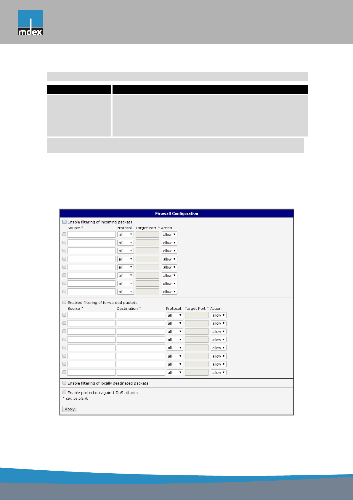
mdex AG • Bäckerbarg 6 • 22889 Tangstedt
1. CONFIGURATION OVER WEB
Continued from previous page
Item Description
Action Type of action:
• allow – access is allowed
• deny – access is denied
Table 32: Forwarding filtering
There is also the possibility to drop a packet whenever request for service which is not in
the router comes (check box named Enable filtering of locally destinated packets). The packet
is dropped automatically without any information.
As a protection against DoS attacks (this means attacks during which the target system
is flooded with plenty of meaningless requirements) is used option named Enable protection
against DoS attacks which limits the number of connections per second for five.
Figure 28: Firewall configuration
41
Page 50
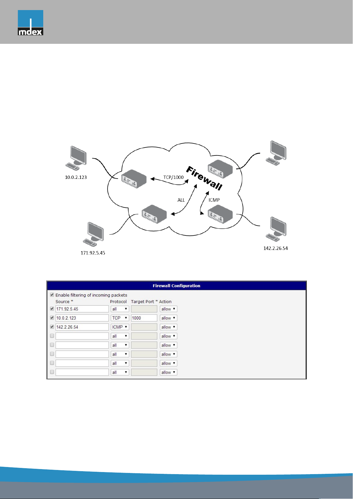
mdex AG • Bäckerbarg 6 • 22889 Tangstedt
1. CONFIGURATION OVER WEB
Example of the firewall configuration:
The router has allowed the following access:
• from address 171.92.5.45 using any protocol
• from address 10.0.2.123 using TCP protocol on port 1000
• from address 142.2.26.54 using ICMP protocol
Figure 29: Topology of example firewall configuration
Figure 30: Example firewall configuration
42
Page 51
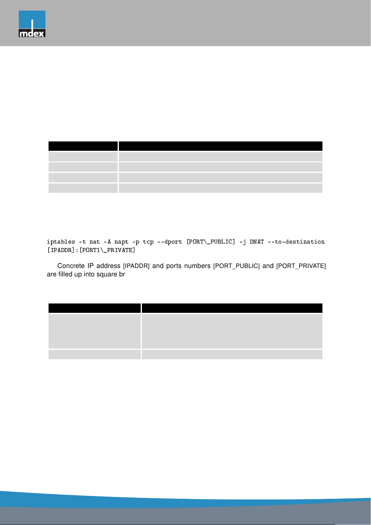
mdex AG • Bäckerbarg 6 • 22889 Tangstedt
1. CONFIGURATION OVER WEB
1.19 NAT configuration
To enter the Network Address Translation configuration, select the NAT menu item. NAT
(Network address Translation / Port address Translation - PAT) is a method of adjusting the network traffic through the router default transcript and/or destination IP addresses often change
the number of TCP/UDP port for walk-through IP packets. The window contains sixteen entries
for the definition of NAT rules.
Item Description
Public Port Public port
Private Port Private port
Type Protocol selection
Server IP address IP address which will be forwarded incoming data
Table 33: NAT configuration
If necessary set more than sixteen rules for NAT rules, then is possible insert into start up
script following script:
iptables -t nat -A napt -p tcp --dport [PORT\_PUBLIC] -j DNAT --to-destination
[IPADDR]:[PORT1\_PRIVATE]
Concrete IP address [IPADDR] and ports numbers [PORT_PUBLIC] and [PORT_PRIVATE]
are filled up into square bracket.
The following items are used to set the routing of all incoming traffic from the PPP to the
connected computer.
Item Description
Send all remaining incoming
packets to default server
Default Server IP Address Send all incoming packets to this IP addresses.
Table 34: Configuration of send all incoming packets
By checking this item and setting the Default Server item
it is possible to put the router into the mode in which all
incoming data from GPRS will be routed to the computer
with the defined IP address.
43
Page 52
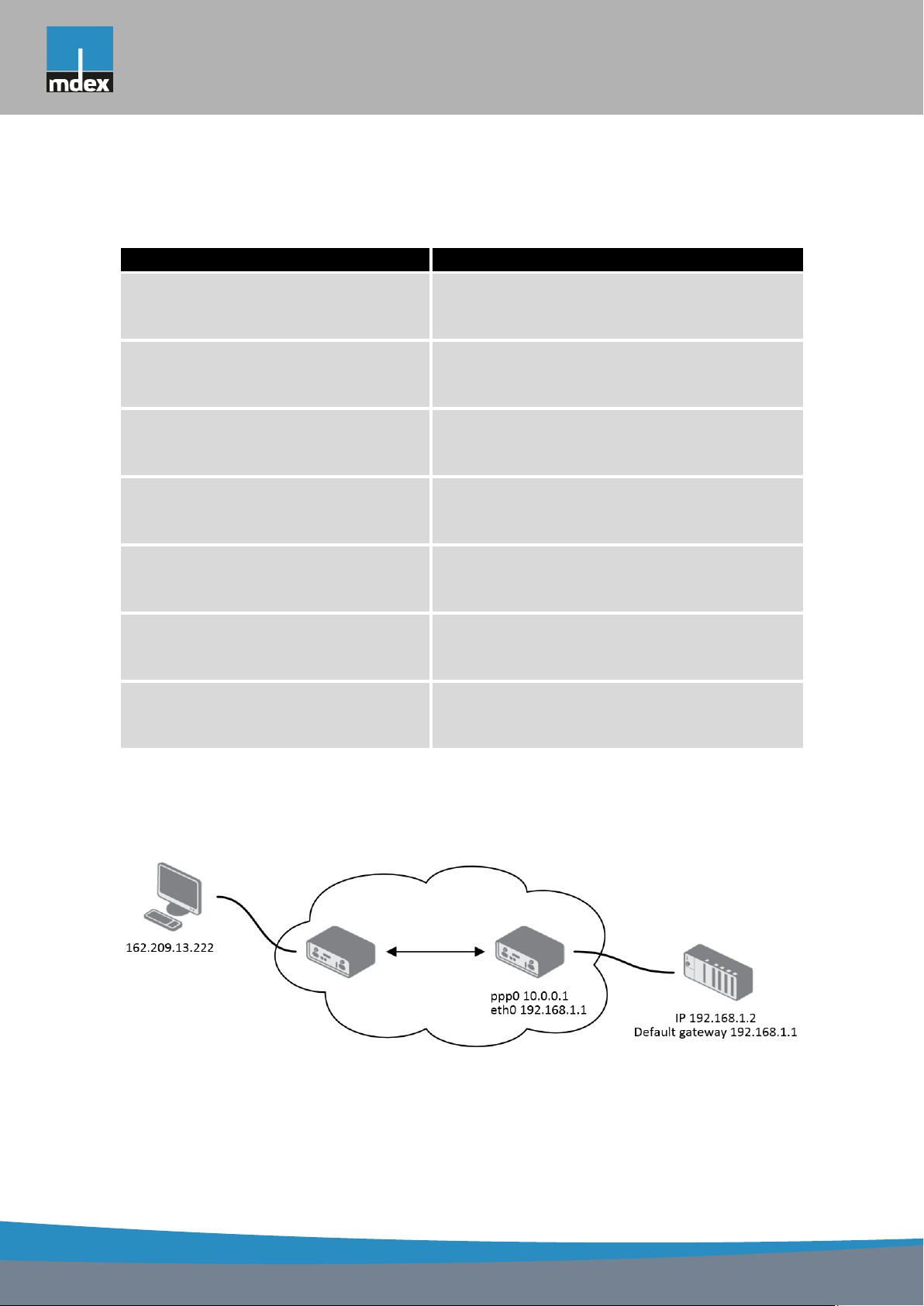
mdex AG • Bäckerbarg 6 • 22889 Tangstedt
1. CONFIGURATION OVER WEB
Enable the following options and enter the port number is allowed remote access to the
router from PPP interface.
Item Description
Enable remote HTTP access on port If this item field and port number is filled in, then
configuration of the router over web interface is
possible (disabled in default configuration).
Enable remote HTTPS access on port If this item field and port number is filled in, then
configuration of the router over web interface is
possible (disabled in default configuration).
Enable remote FTP access on port Choice this item and port number makes it pos-
sible to access over FTP (disabled in default
configuration).
Enable remote SSH access on port Choice this item and port number makes it pos-
sible to access over SSH (disabled in default
configuration).
Enable remote Telnet access on port Choice this item and port number makes it pos-
sible to access over Telnet (disabled in default
configuration).
Enable remote SNMP access on port Choice this item and port number makes it pos-
sible to access to SNMP agent (disabled in default configuration).
Masquerade outgoing packets Choice Masquerade (alternative name for the
NAT system) item option turns the system address translation NAT.
Table 35: Remote access configuration
Example of the configuration with one connection equipment on the router:
Figure 31: Topology of example NAT configuration 1
44
Page 53
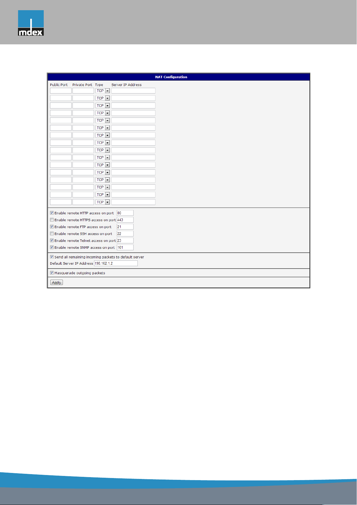
mdex AG • Bäckerbarg 6 • 22889 Tangstedt
1. CONFIGURATION OVER WEB
Figure 32: Example NAT configuration 1
In these configurations it is important to have marked choice of Send all remaining incom-
ing packets it default server, IP address in this case is the address of the device behind the
router. Connected equipment behind the router must have set Default Gateway on the router.
Connected device replies, while PING on IP address of SIM card.
45
Page 54
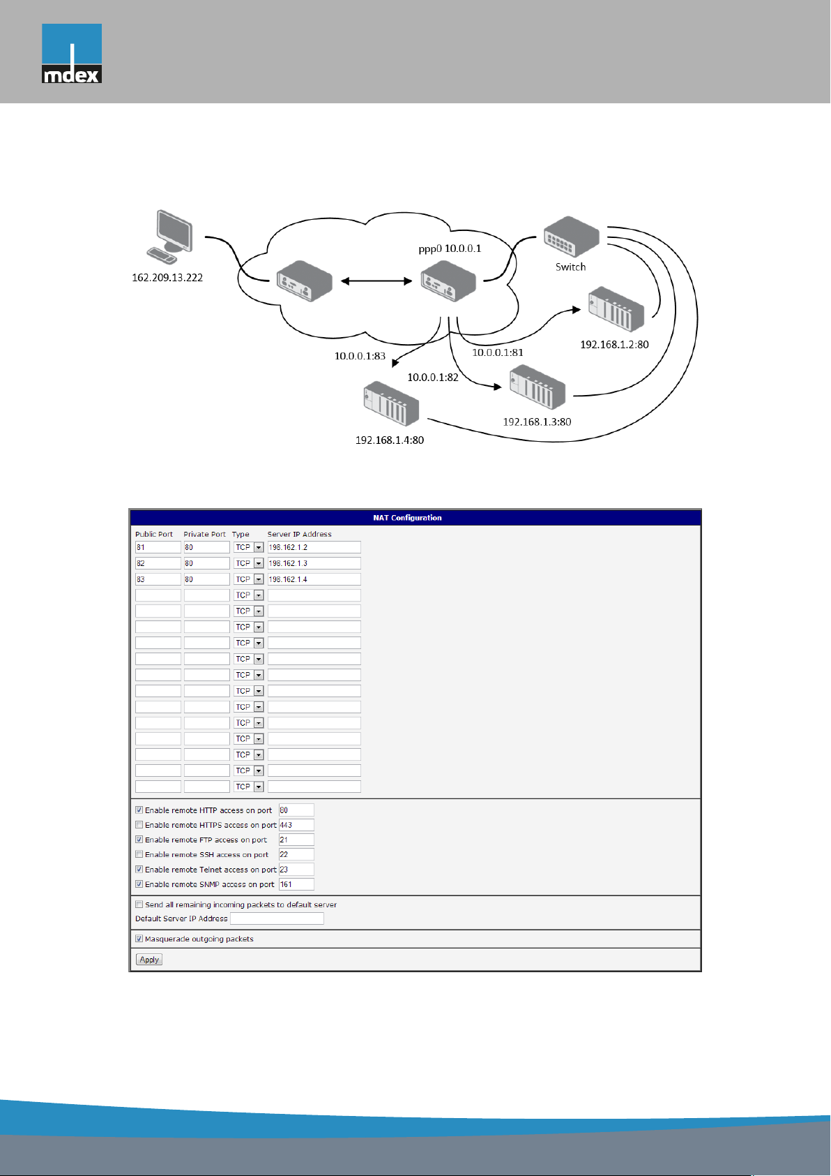
mdex AG • Bäckerbarg 6 • 22889 Tangstedt
1. CONFIGURATION OVER WEB
Example of the configuration with more connected equipment:
Figure 33: Topology of example NAT configuration 2
Figure 34: Example NAT configuration 2
46
Page 55
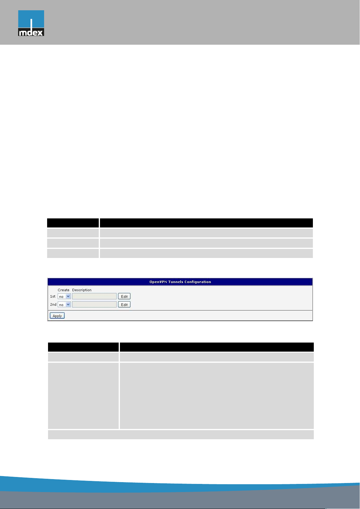
mdex AG • Bäckerbarg 6 • 22889 Tangstedt
1. CONFIGURATION OVER WEB
In this example there is more equipment connected behind the router, using a Switch.
Every device connected behind the router has its own IP address and this is the address to fill
in the Server IP Address field in the NAT configuration. These devices are all communicating
on the port 80, but you can set the Port Forwarding in the NAT configuration ? see Figure 31
? Public Port and Private Port fields. It is now configured to access 192.168.1.2:80 socket
behind the router when accessing 10.0.0.1:81 from the Internet and so on. If you send the ping
request to the public IP address of the router (10.0.0.1), the router will respond as usual (not
forwarding). If you access the IP address 10.0.0.1 in the browser (it is port 80), the router’s
Web interface will come up since Enable remote HTTP access on port 80 is checked.
1.20 OpenVPN tunnel configuration
OpenVPN tunnel configuration can be called up by option OpenVPN item in the menu.
OpenVPN tunnel allows protected connection of two networks LAN to the one which looks like
one homogenous. In the OpenVPN Tunnels Configuration window are two rows, each row for
one configured OpenVPN tunnel.
Item Description
Create Enables the individual tunnels
Description Displays a name of the tunnel specified in the configuration form
Edit Configuration of OpenVPN tunnel
Table 36: Overview OpenVPN tunnels
Figure 35: OpenVPN tunnels configuration
Item Description
Description Description (or name) of tunnel
Protocol Communication protocol:
• UDP – OpenVPN will communicate using UDP
• TCP server – OpenVPN will communicate using TCP in
server mode
• TCP client – OpenVPN will communicate using TCP in
client mode
Continued on next page
47
Page 56

mdex AG • Bäckerbarg 6 • 22889 Tangstedt
1. CONFIGURATION OVER WEB
Continued from previous page
Item Description
UDP/TCP port Port of the relevant protocol (UDP or TCP)
Remote IP Address IP address of opposite tunnel side (domain name can be used)
Remote Subnet IP address of a network behind opposite tunnel side
Remote Subnet Mask Subnet mask of a network behind opposite tunnel side
Redirect Gateway Allows to redirect all traffic on Ethernet
Local Interface IP
Address
Remote Interface
IP Address
Ping Interval Defines the time interval after which sends a message to oppo-
Ping Timeout Defines the time interval during which the router waits for a mes-
Renegotiate Interval Sets renegotiate period (reauthorization) of the OpenVPN tun-
Max Fragment Size Defines the maximum size of a sent packet
Compression Sent data can be compressed:
Defines the IP address of a local interface
Defines the IP address of the interface of opposite tunnel side
site side of tunnel for checking the existence of the tunnel.
sage sent by the opposite side. For proper verification of OpenVPN tunnel, Ping Timeout must be greater than Ping Interval.
nel. This parameter can be set only when Authenticate Mode is
set to username/password or X.509 certificate. After this time
period, router changes the tunnel encryption to ensure the continues safety of the tunnel.
• none – no compression is used
• LZO – a lossless compression is used (must be set on both
sides of the tunnel!)
NAT Rules Applies NAT rules to the OpenVPN tunnel:
• not applied – NAT rules are not applied to the OpenVPN
tunnel
• applied – NAT rules are applied to the OpenVPN tunnel
Continued on next page
48
Page 57

mdex AG • Bäckerbarg 6 • 22889 Tangstedt
1. CONFIGURATION OVER WEB
Continued from previous page
Item Description
Authenticate Mode Sets authentication mode:
• none – no authentication is set
• Pre-shared secret – sets the shared key for both sides of
the tunnel
• Username/password – enables authentication using CA
Certificate, Username and Password
• X.509 Certificate (multiclient) – enables X.509 authenti-
cation in multiclient mode
• X.509 Certificate (client) – enables X.509 authentication
in client mode
• X.509 Certificate (server) – enables X.509 authentication
in server mode
Pre-shared Secret Authentication using pre-shared secret can be used for all offered
authentication mode.
CA Certificate Auth. using CA Certificate can be used for username/password
and X.509 Certificate modes.
DH Parameters Protocol for exchange key DH parameters can be used for X.509
Certificate authentication in server mode.
Local Certificate This authentication certificate can be used for X.509 Certificate
authentication mode.
Local Private Key It can be used for X.509 Certificate authentication mode.
Username Authentication using a login name and password authentication
can be used for username/password mode.
Password Authentication using a login name and password authentication
can be used for username/password mode.
Extra Options Allows to define additional parameters of OpenVPN tunnel such
as DHCP options etc. Parameters are introduced by two dashes.
For possible parameters see the help in the router via SSH – run
the
openvpnd --help
Table 37: OpenVPN tunnels configuration
command.
49
Page 58
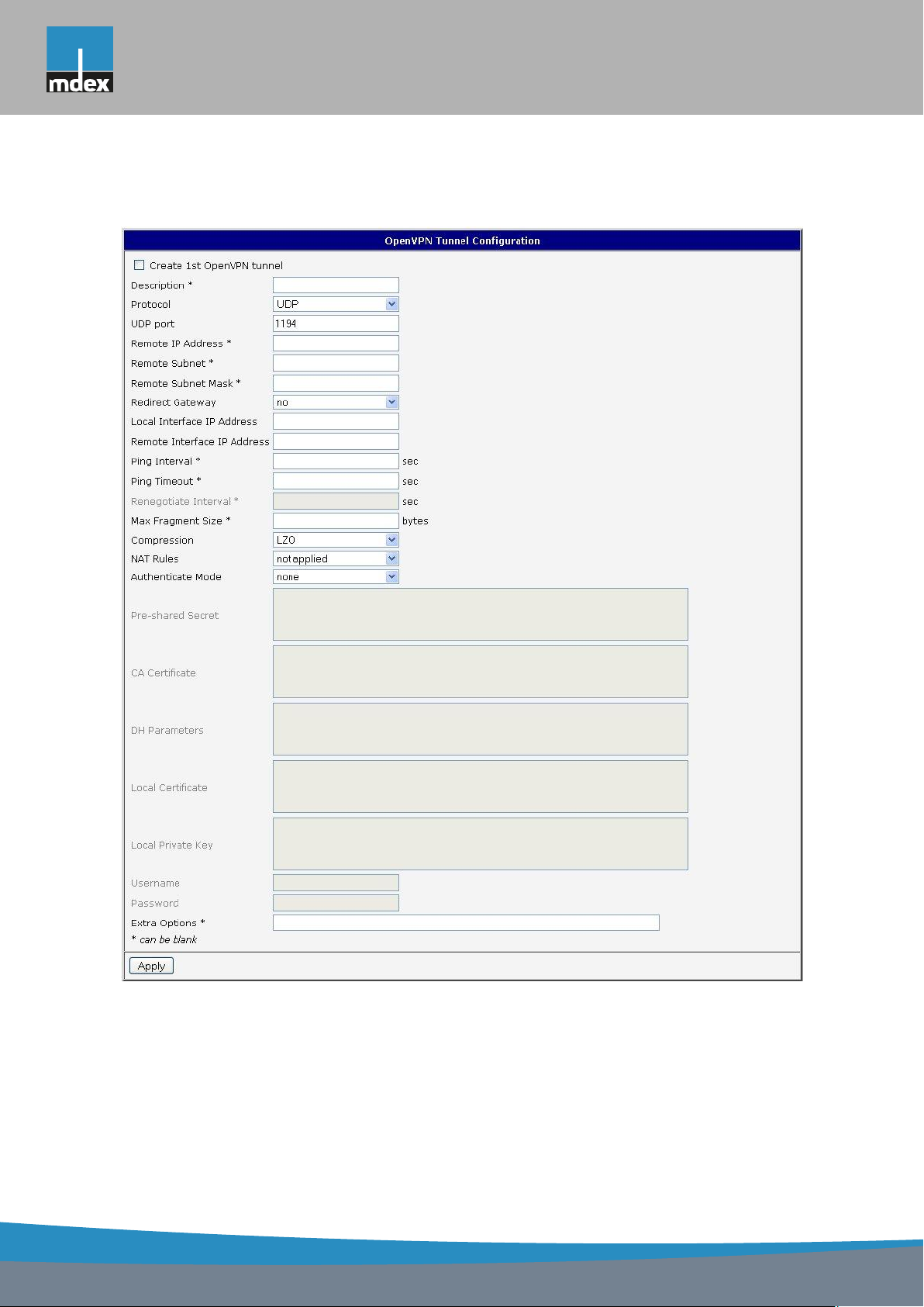
mdex AG • Bäckerbarg 6 • 22889 Tangstedt
1. CONFIGURATION OVER WEB
The changes in settings will apply after pressing the Apply button.
Figure 36: OpenVPN tunnel configuration
50
Page 59
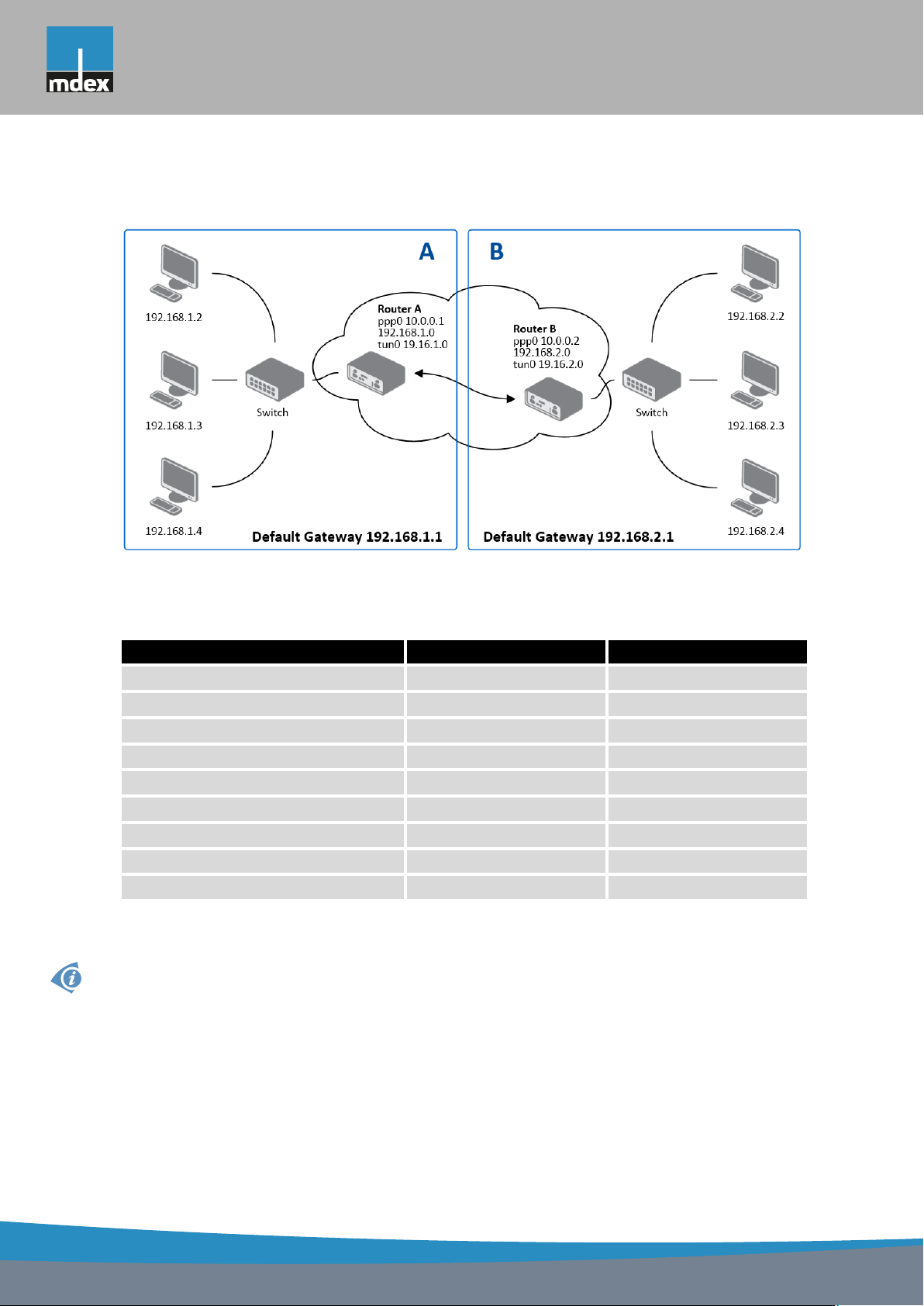
mdex AG • Bäckerbarg 6 • 22889 Tangstedt
1. CONFIGURATION OVER WEB
Example of the OpenVPN tunnel configuration:
Figure 37: Topology of example OpenVPN configuration
OpenVPN tunnel configuration:
Configuration A B
Protocol UDP UDP
UDP Port 1194 1194
Remote IP Address 10.0.0.2 10.0.0.1
Remote Subnet 192.168.2.0 192.168.1.0
Remote Subnet Mask 255.255.255.0 255.255.255.0
Local Interface IP Address 19.16.1.0 19.16.2.0
Remote Interface IP Address 19.16.2.0 19.18.1.0
Compression LZO LZO
Authenticate mode none none
Table 38: Example OpenVPN configuration
Examples of different options for configuration and authentication of OpenVPN tunnel can
be found in the application note OpenVPN.
51
Page 60
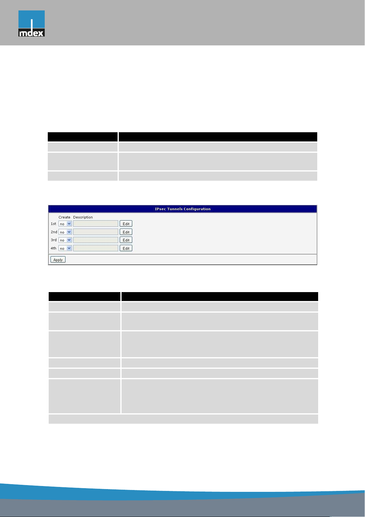
mdex AG • Bäckerbarg 6 • 22889 Tangstedt
1. CONFIGURATION OVER WEB
1.21 IPsec tunnel configuration
IPsec tunnel configuration can be called up by option IPsec item in the menu. IPsec tunnel
allows protected (encrypted) connection of two networks LAN to the one which looks like one
homogenous. In the IPsec Tunnels Configuration window are four rows, each row for one
configured one IPsec tunnel.
Item Description
Create This item enables the individual tunnels.
Description This item displays the name of the tunnel specified in the config-
uration of the tunnel.
Edit Configuration IPsec tunnel.
Table 39: Overview IPsec tunnels
Figure 38: IPsec tunnels configuration
Item Description
Description Name (description) of the tunnel
Remote IP Address IP address of remote side of the tunnel. It is also possible to enter
the domain name.
Remote ID Identifier (ID) of remote side of the tunnel. It consists of two parts:
hostname and domain-name (more information can be found under the table).
Remote Subnet IP address of a network behind remote side of the tunnel
Remote Subnet Mask Subnet mask of a network behind remote side of the tunnel
Remote Protocol/Port Specifies Protocol/Port of remote side of the tunnel. The general
form is protocol/port, for example 17/1701 for UDP (protocol 17)
and port 1701. It is also possible to enter only the number of
protocol, however, the above mentioned format is preferred.
Continued on next page
52
Page 61

mdex AG • Bäckerbarg 6 • 22889 Tangstedt
1. CONFIGURATION OVER WEB
Continued from previous page
Item Description
Local ID Identifier (ID) of local side of the tunnel. It consists of two parts:
hostname and domain-name (more information can be found under the table).
Local Subnet IP address of a local network
Local Subnet Mask Subnet mask of a local network
Local Protocol/Port Specifies Procokol/Port of a local network. The general form is
protocol/port, for example 17/1701 for UDP (protocol 17) and
port 1701. It is also possible to enter only the number of protocol,
however, the above mentioned format is preferred.
Encapsulation Mode IPsec mode (according to the method of encapsulation) – You
can choose tunnel (entire IP datagram is encapsulated) or trans-
port (only IP header).
NAT traversal If address translation is used between two end points of the tun-
nel, it needs to enable NAT Traversal.
IKE Mode Defines mode for establishing connection (main or aggressive).
If the aggressive mode is selected, establishing of IPsec tunnel
will be faster, but encryption will set permanently on 3DES-MD5.
We recommend not to use aggressive mode due to a lower
security!
IKE Algorithm Way of algorithm selection:
• auto – encryption and hash alg. are selected automatically
• manual – encryption and hash alg. are defined by the user
IKE Encryption Encryption algorithm – 3DES, AES128, AES192, AES256
IKE Hash Hash algorithm – MD5, SHA1, SHA256, SHA384 or SHA512
IKE DH Group Diffie-Hellman groups determine the strength of the key used in
the key exchange process. Higher group numbers are more secure, but require additional time to compute the key. Group with
higher number provides more security, but requires more processing time.
ESP Algorithm Way of algorithm selection:
• auto – encryption and hash alg. are selected automatically
• manual – encryption and hash alg. are defined by the user
ESP Encryption Encryption algorithm – DES, 3DES, AES128, AES192, AES256
Continued on next page
53
Page 62

mdex AG • Bäckerbarg 6 • 22889 Tangstedt
1. CONFIGURATION OVER WEB
Continued from previous page
Item Description
ESP Hash Hash algorithm – MD5, SHA1, SHA256, SHA384 or SHA512
PFS Ensures that derived session keys are not compromised if one of
the private keys is compromised in the future
PFS DH Group Diffie-Hellman group number (see IKE DH Group)
Key Lifetime Lifetime key data part of tunnel. The minimum value of this pa-
rameter is 60 s. The maximum value is 86400 s.
IKE Lifetime Lifetime key service part of tunnel. The minimum value of this
parameter is 60 s. The maximum value is 86400 s.
Rekey Margin Specifies how long before connection expiry should attempt to
negotiate a replacement begin. Maximum value must be less
than half of IKE and Key Lifetime parameters.
Rekey Fuzz Percentage extension of Rekay Margin time
DPD Delay Time after which the IPsec tunnel functionality is tested
DPD Timeout The period during which device waits for a response
Authenticate Mode Using this parameter can be set authentication:
• Pre-shared key – sets the shared key for both sides of the
tunnel
• X.509 Certificate – allows X.509 authentication in multi-
client mode
Pre-shared Key Shared key for both sides of the tunnel to Pre-shared key authen-
ticate
CA Certificate Certificate for X.509 authentication
Remote Certificate Certificate for X.509 authentication
Local Certificate Certificate for X.509 authentication
Local Private Key Private key for X.509 authentication
Local Passphrase Passphrase for X.509 authentication
Extra Options Use this parameter to define additional parameters of the IPsec
tunnel, for example secure parameters etc.
Table 40: IPsec tunnel configuration
54
Page 63

mdex AG • Bäckerbarg 6 • 22889 Tangstedt
1. CONFIGURATION OVER WEB
IPsec supports the following types of identifiers (ID) of both tunnel sides (Remote ID and
Local ID items):
• IP address (e.g. 192.168.1.1)
• DN (e.g. C=CZ,O=Conel,OU=TP,CN=A)
• FQDN (e.g. @director.conel.cz) – in front of FQDN must always be @
• User FQDN (e.g. [email protected])
The certificates and private keys have to be in PEM format. As certificate it is possible to
use only certificate which has start and stop tag certificate.
Random time, after which it will re-exchange of new keys are defined:
Lifetime - (Rekey margin + random value in range (from 0 to Rekey margin * Rekey Fuzz/100))
By default, the repeated exchange of keys held in the time range:
• Minimal time: 1h - (9m + 9m) = 42m
• Maximal time: 1h - (9m + 0m) = 51m
When setting the times for key exchange is recommended to leave the default setting in
which tunnel has guaranteed security. When set higher time, tunnel has smaller operating
costs and smaller the safety. Conversely, reducing the time, tunnel has higher operating costs
and higher safety of the tunnel.
The changes in settings will apply after pressing the Apply button.
55
Page 64
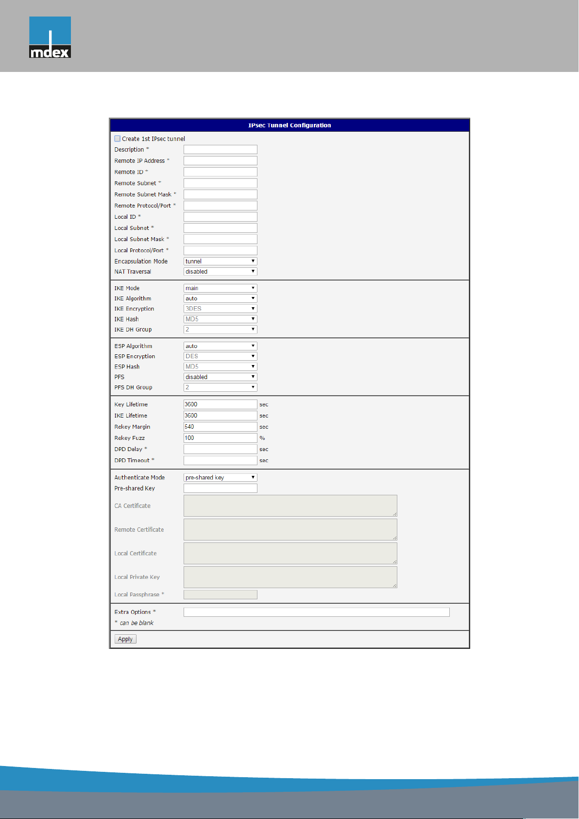
mdex AG • Bäckerbarg 6 • 22889 Tangstedt
1. CONFIGURATION OVER WEB
Figure 39: IPsec tunnels configuration
56
Page 65
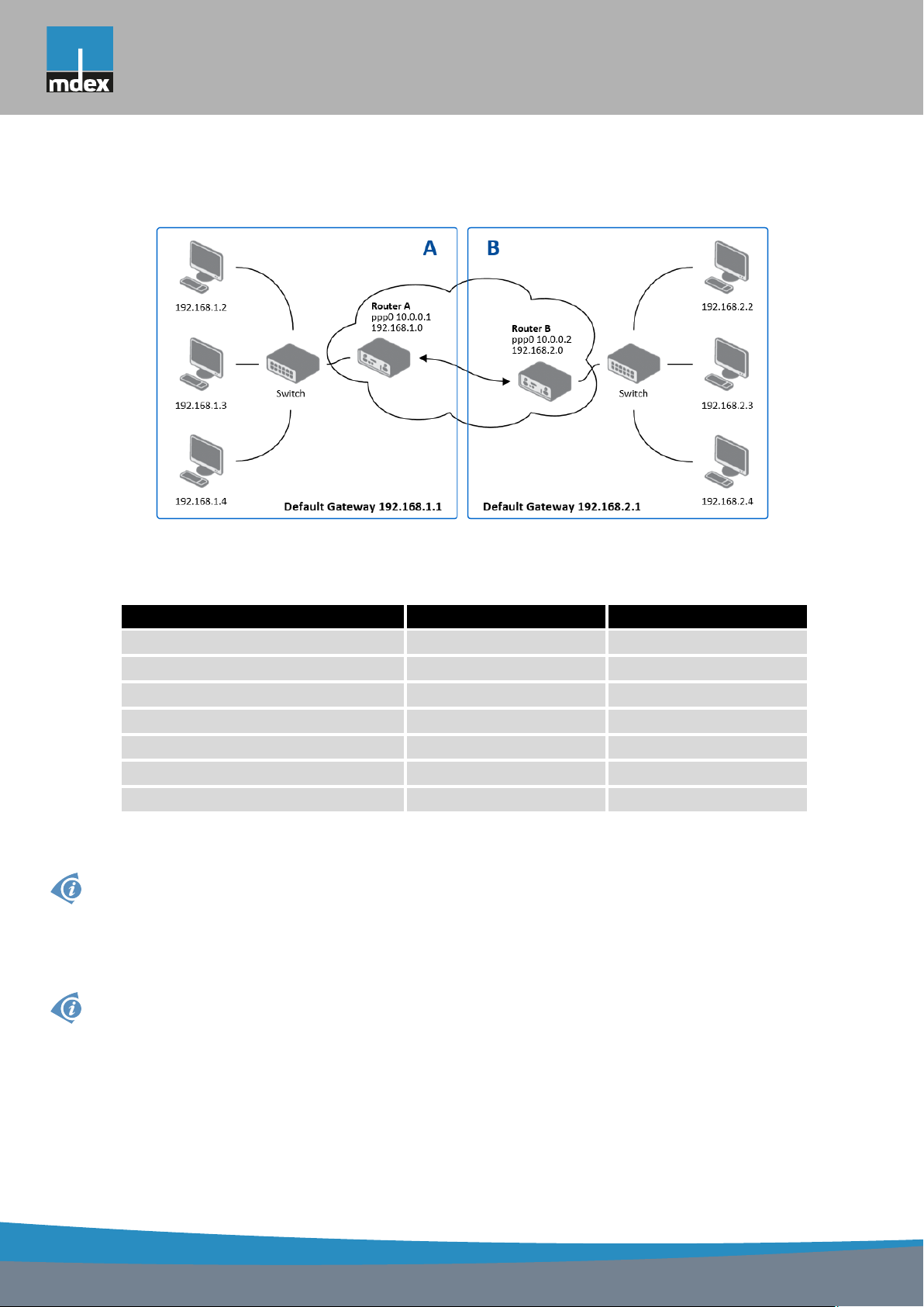
mdex AG • Bäckerbarg 6 • 22889 Tangstedt
Example of the IPSec Tunnel configuration:
1. CONFIGURATION OVER WEB
Figure 40: Topology of example IPsec configuration
IPsec tunnel configuration:
Configuration A B
Remote IP Address 10.0.0.2 10.0.0.1
Remote Subnet 192.168.2.0 192.168.1.0
Remote Subnet Mask 255.255.255.0 255.255.255.0
Local Subnet 192.168.1.0 192.168.2.0
Local Subnet Mas: 255.255.255.0 255.255.255.0
Authenticate mode pre-shared key pre-shared key
Pre-shared key test test
Table 41: Example IPsec configuration
Examples of different options for configuration and authentication of IPsec tunnel can be
found in the application note IPsec.
1.22 GRE tunnels configuration
GRE is an unencrypted protocol.
To enter the GRE tunnels configuration, select the GRE menu item. The GRE tunnel is
used for connection of two networks to one that appears as one homogenous. It is possible
to configure up to four GRE tunnels. In the GRE Tunnels Configuration window are four rows,
each row for one configured GRE tunnel.
57
Page 66
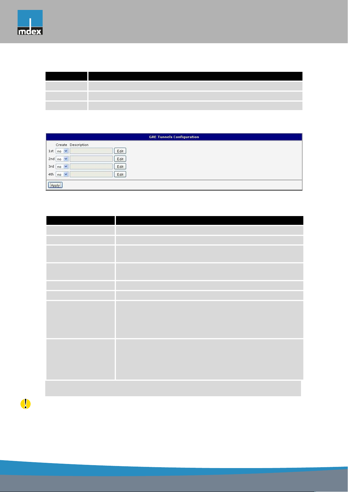
mdex AG • Bäckerbarg 6 • 22889 Tangstedt
1. CONFIGURATION OVER WEB
Item Description
Create Enables the individual tunnels
Description Displays the name of the tunnel specified in the configuration form
Edit Configuration of GRE tunnel
Table 42: Overview GRE tunnels
Figure 41: GRE tunnels configuration
Item Description
Description Description of tunnel.
Remote IP Address IP address of the remote side of the tunnel
Local Interface IP
Address
Remote Interface IP
Address
Remote Subnet IP address of the network behind the remote side of the tunnel
Remote Subnet Mask Mask of the network behind the remote side of the tunnel
Multicasts Enables/disables multicast:
Pre-shared Key An optional value that defines the 32bit shared key in numeric
IP address of the local side of the tunnel
IP address of the remote side of the tunnel
• disabled – multicast disabled
• enabled – multicast enabled
format, through which the filtered data through the tunnel. This
key must be defined on both routers as same, otherwise the
router will drop received packets. Using this key, the data do not
provide a tunnel through.
Table 43: GRE tunnel configuration
Attention, GRE tunnel doesn?t connect itself via NAT.
The changes in settings will apply after pressing the Apply button.
58
Page 67
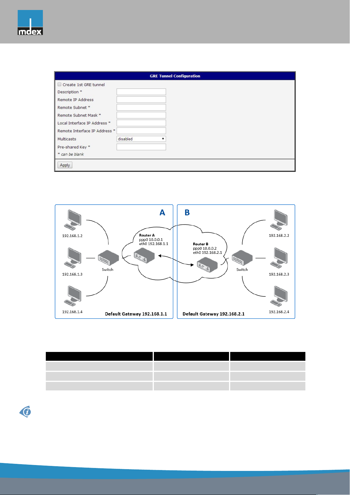
mdex AG • Bäckerbarg 6 • 22889 Tangstedt
Figure 42: GRE tunnel configuration
Example of the GRE Tunnel configuration:
1. CONFIGURATION OVER WEB
Figure 43: Topology of GRE tunnel configuration
GRE tunnel Configuration:
Configuration A B
Remote IP Address 10.0.0.2 10.0.0.1
Remote Subnet 192.168.2.0 192.168.1.0
Remote Subnet Mask 255.255.255.0 255.255.255.0
Table 44: Example GRE tunnel configuration
Examples of different options for configuration of GRE tunnel can be found in the application note GRE Tunnel.
59
Page 68
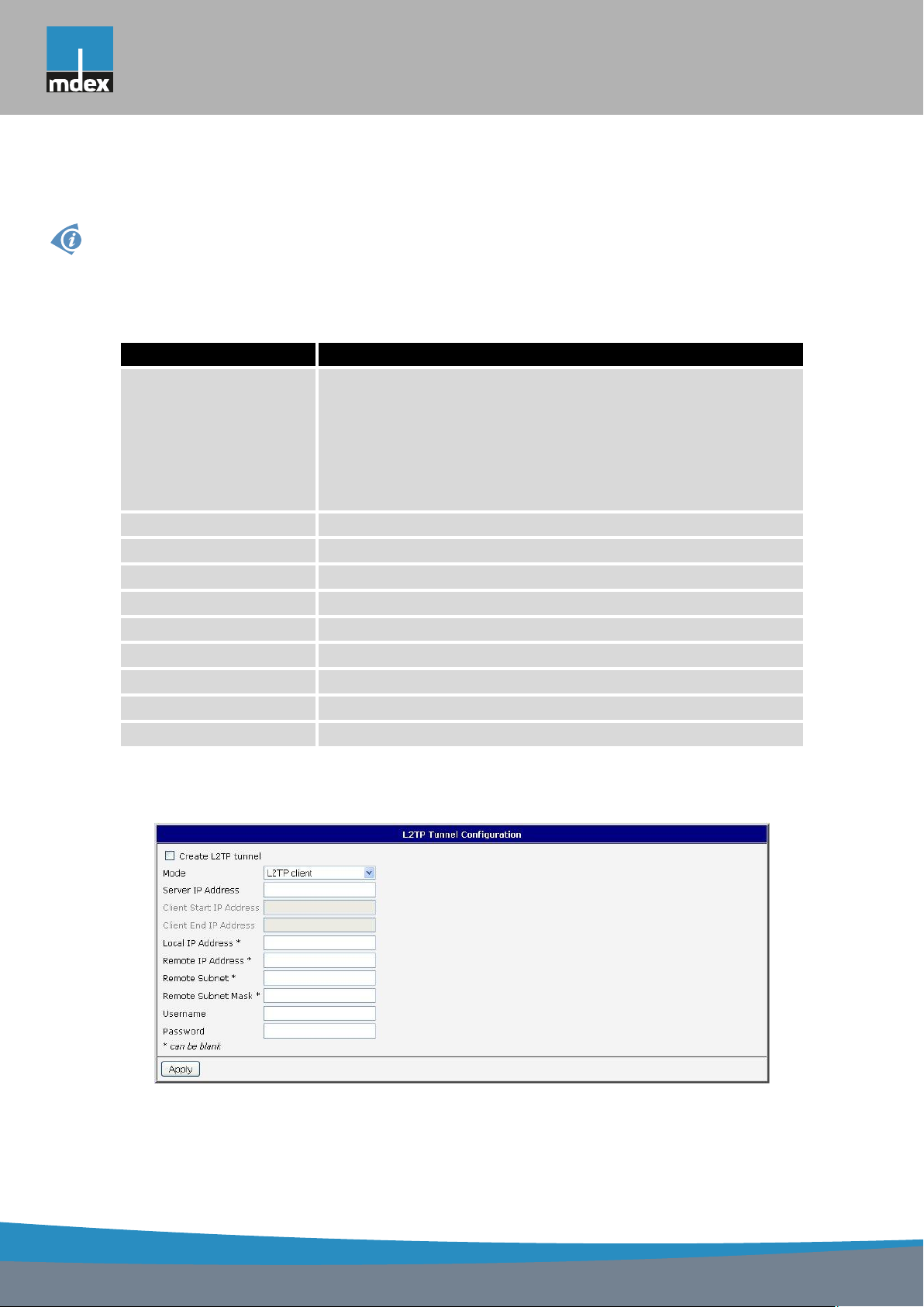
mdex AG • Bäckerbarg 6 • 22889 Tangstedt
1. CONFIGURATION OVER WEB
1.23 L2TP tunnel configuration
L2TP is an unencrypted protocol.
To enter the L2TP tunnels configuration, select the L2TP menu item. L2TP tunnel allows
protected connection by password of two networks LAN to the one which it looks like one
homogenous. The tunnels are active after selecting Create L2TP tunnel.
Item Description
Mode L2TP tunnel mode on the router side:
• L2TP server – in the case of a server must be defined IP
address range offered by the server
• L2TP client – in case of client must be defined the IP
address of the server
Server IP Address IP address of server
Client Start IP Address Start IP address in range, which is offered by server to clients
Client End IP Address End IP address in range, which is offered by server to clients
Local IP Address IP address of the local side of the tunnel
Remote IP Address IP address of the remote side of the tunnel
Remote Subnet Address of the network behind the remote side of the tunnel
Remote Subnet Mask The mask of the network behind the remote side of the tunnel
Username Username for login to L2TP tunnel
Password Password for login to L2TP tunnel
Table 45: L2TP tunnel configuration
The changes in settings will apply after pressing the Apply button.
Figure 44: L2TP tunnel configuration
60
Page 69
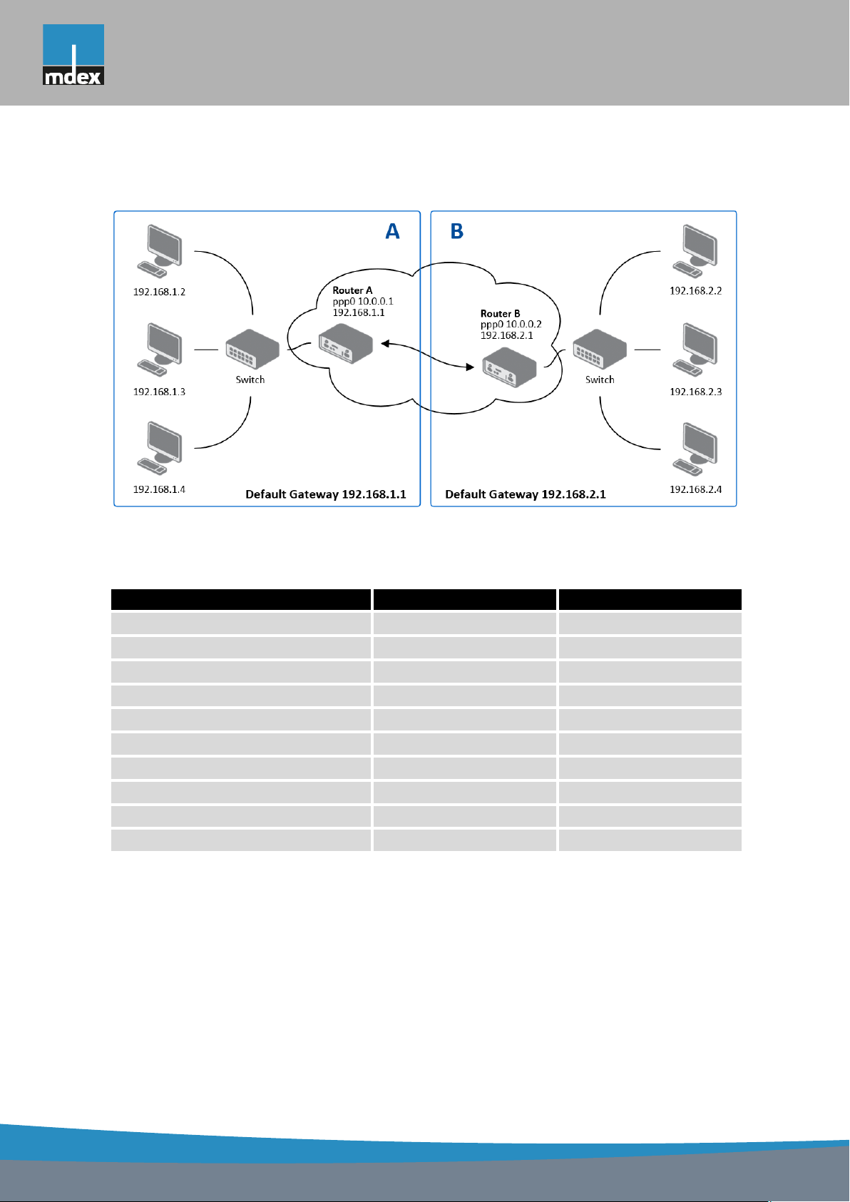
mdex AG • Bäckerbarg 6 • 22889 Tangstedt
Example of the L2TP Tunnel configuration:
1. CONFIGURATION OVER WEB
Figure 45: Topology of example L2TP tunnel configuration
Configuration of the L2TP tunnel:
Configuration A B
Mode L2TP Server L2TP Client
Server IP Address — 10.0.0.1
Client Start IP Address 192.168.1.2 —
Client End IP Address 192.168.1.254 —
Local IP Address 192.168.1.1 —
Remote IP Address — —
Remote Subnet 192.168.2.0 192.168.1.0
Remote Subnet Mask 255.255.255.0 255.255.255.0
Username username username
Password password password
Table 46: Example L2TP tunel configuration
61
Page 70
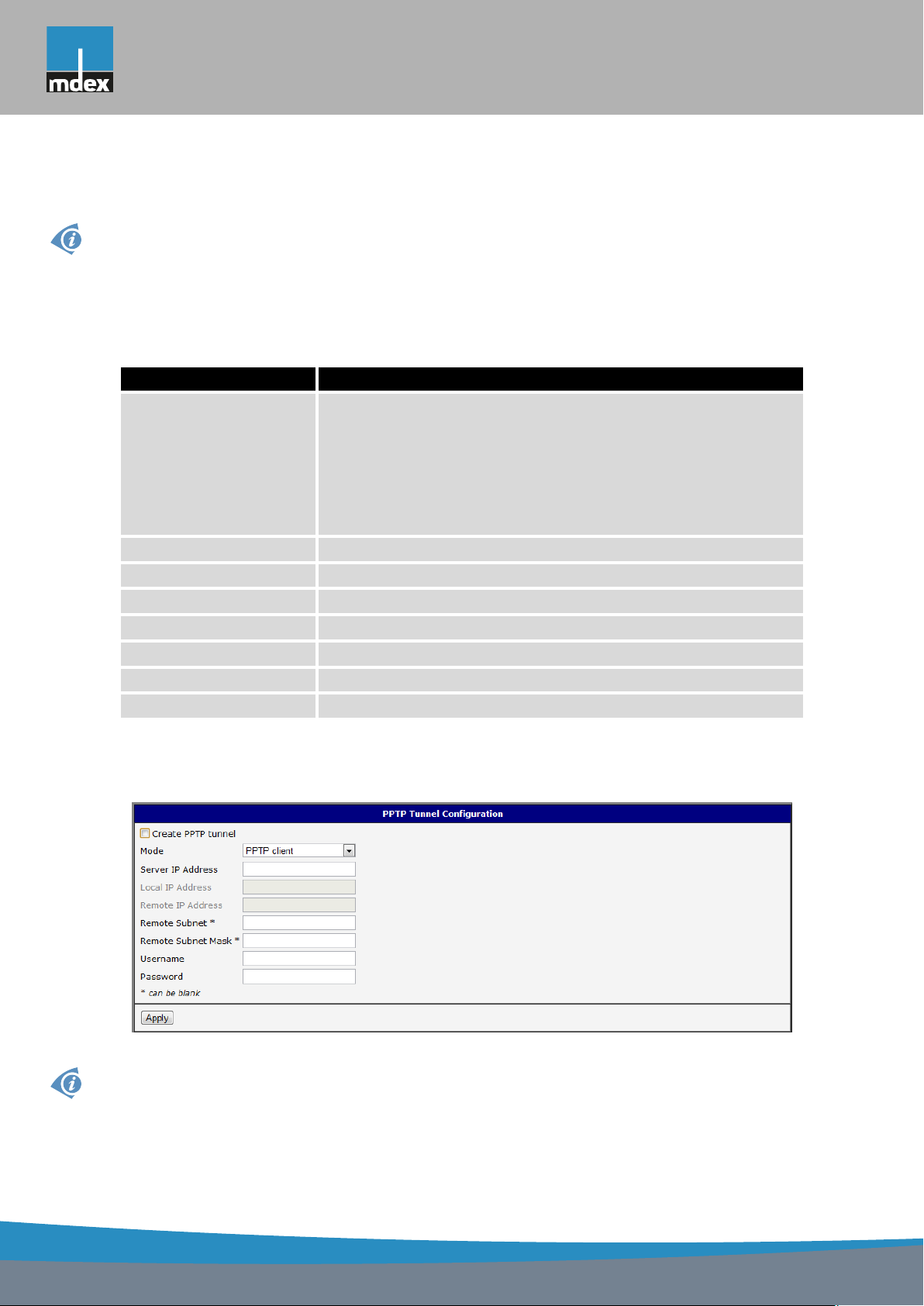
mdex AG • Bäckerbarg 6 • 22889 Tangstedt
1. CONFIGURATION OVER WEB
1.24 PPTP tunnel configuration
PPTP is an unencrypted protocol.
To enter the PPTP tunnels configuration, select the PPTP menu item. PPTP tunnel allows
protected connection by password of two networks LAN to the one which it looks like one
homogenous. It is a similar method of VPN execution as L2TP. The tunnels are active after
selecting Create PPTP tunnel.
Item Description
Mode PPTP tunnel mode on the router side:
• PPTP server – in the case of a server must be defined
IP address range offered by the server
• PPTP client – in case of client must be defined the IP
address of the server
Server IP Address IP address of server
Local IP Address IP address of the local side of the tunnel
Remote IP Address IP address of the remote side of the tunnel
Remote Subnet Address of the network behind the remote side of the tunnel
Remote Subnet Mask The mask of the network behind the remote side of the tunnel
Username Username for login to PPTP tunnel
Password Password for login to PPTP tunnel
Table 47: PPTP tunnel configuration
The changes in settings will apply after pressing the Apply button.
Figure 46: PPTP tunnel configuration
Since firmware 3.0.9 is added support for PPTP passthrough, which means that it is pos-
sible to create a tunnel through router.
62
Page 71
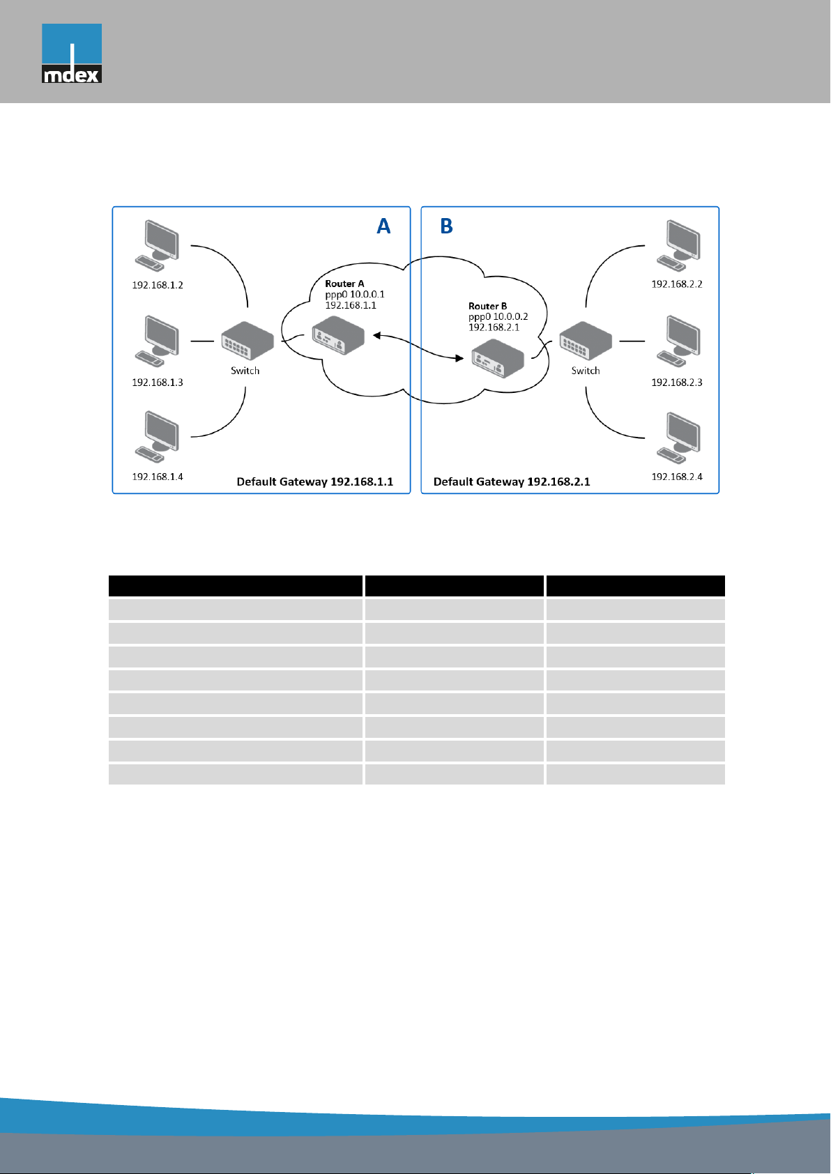
mdex AG • Bäckerbarg 6 • 22889 Tangstedt
Example of the PPTP Tunnel configuration:
1. CONFIGURATION OVER WEB
Figure 47: Topology of example PPTP tunnel configuration
Configuration of the PPTP tunnel:
Configuration A B
Mode PPTP Server PPTP Client
Server IP Address — 10.0.0.1
Local IP Address 192.168.1.1 —
Remote IP Address — —
Remote Subnet 192.168.2.0 192.168.1.0
Remote Subnet Mask 255.255.255.0 255.255.255.0
Username username username
Password password password
Table 48: Example PPTP tunel configuration
63
Page 72
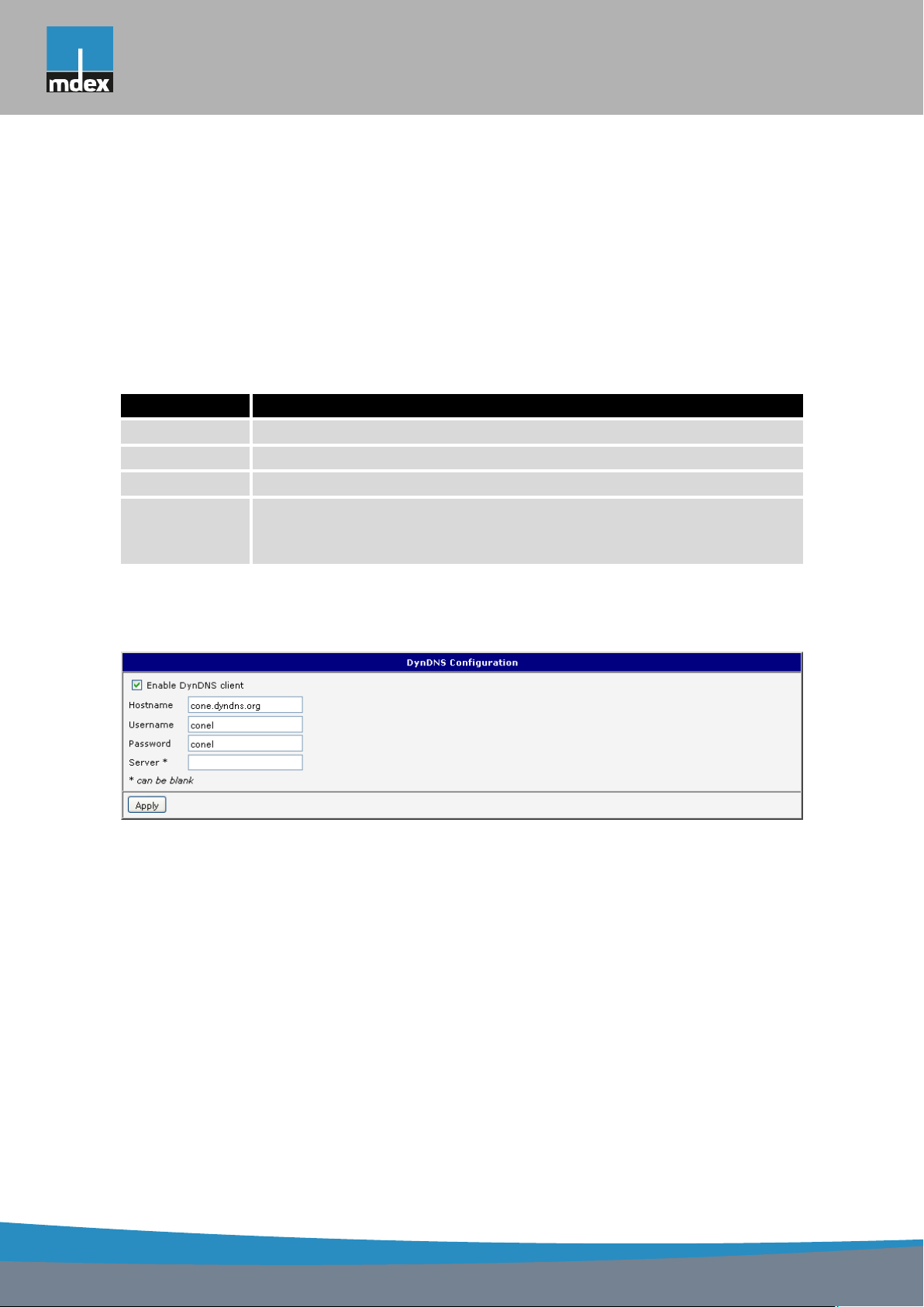
mdex AG • Bäckerbarg 6 • 22889 Tangstedt
1. CONFIGURATION OVER WEB
1.25 DynDNS client configuration
With the DynDNS service you can access the router remotely using an easy to remember
custom hostname. This client monitors the router’s IP address and update it whenever it
changes. To make DynDNS work it is necessary to have a public IP address (static or dynamic)
and an active account at www.dyndns.org (Remote Access service).
DynDNS client Configuration is accessible in the DynDNS item in the menu. There has to
be registered custom domain (third-level) and account information defined in the configuration
form.
Item Description
Hostname Third order domain registered on server www.dyndns.org
Username Username for login to DynDNS server
Password Password for login to DynDNS server
Server If you want to use another DynDNS service than www.dyndns.org, then
enter the update server service to this item. If this item is left blank, it
uses the default server members.dyndns.org.
Table 49: DynDNS configuration
Example of the DynDNS client configuration with domain conel.dyndns.org:
Figure 48: Example of DynDNS configuration
64
Page 73
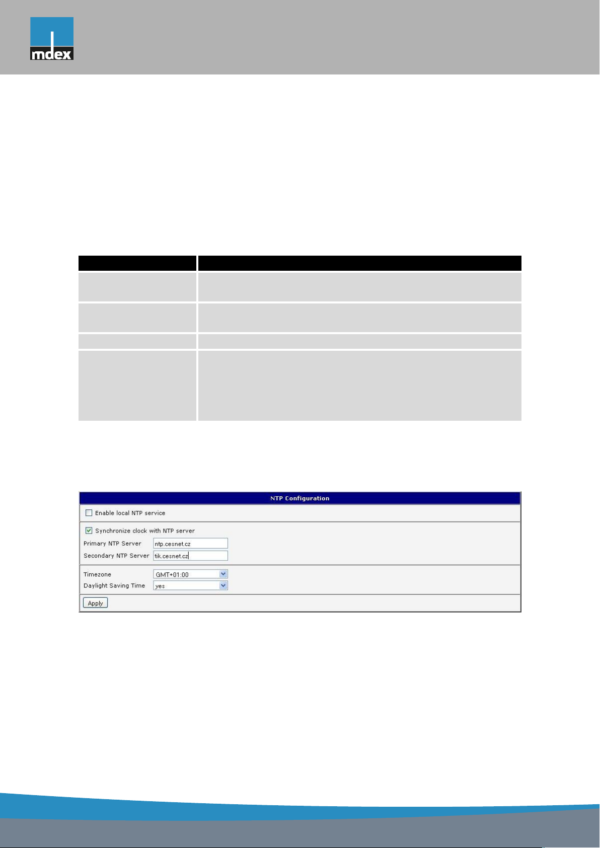
mdex AG • Bäckerbarg 6 • 22889 Tangstedt
1. CONFIGURATION OVER WEB
1.26 NTP client configuration
NTP client Configuration can be called up by option NTP item in the menu. NTP (Network
Time Protocol) allows set the exact time to the router from the servers, which provide the exact
time on the network.
By parameter Enable local NTP service router is set to a mode in which it operates as an
NTP server for other devices in the LAN behind the router.
By parameter Enable local NTP service it is possible to set the router in mode, that it can
serve as NTP server for other devices.
Item Description
Primary NTP Server
Address
Secondary NTP
Server Address
Timezone By this parameter it is possible to set the time zone of the router
Daylight Saving Time Using this parameter can be defined time shift:
IP or domain address primary NTP server.
IP or domain address secondary NTP server.
• No – time shift is disabled
• Yes – time shift is allowed
Table 50: NTP configuration
Example of the NTP conf. with set primary (ntp.cesnet.cz) and secondary (tik.cesnet.cz)
NTP server and with daylight saving time:
Figure 49: Example of NTP configuration
65
Page 74

mdex AG • Bäckerbarg 6 • 22889 Tangstedt
1. CONFIGURATION OVER WEB
1.27 SNMP configuration
To enter the SNMP configuration it is possible with SNMP agent v1/v2 or v3 configuration
which sends information about the router, eventually about the status of the expansion port
CNT or MBUS.
SNMP (Simple Network Management Protocol) provides status information about network
elements such as routers or end computers.
Item Description
Name Designation of the router.
Location Placing of the router.
Contact Person who manages the router together with information how to contact
this person.
Table 51: SNMP agent configuration
Enabling SNMPv1/v2 is performed using the Enable SNMPv1/v2 access item. It is also
necessary to define a password for access to the SNMP agent (Community). Standardly is
used public that is predefined.
The Enable SNMPv3 access item allows you to enable SNMPv3. Then you must define
the following parameters:
Item Description
Username User name
Authentication Encryption algorithm on the Authentication Protocol that is
used to ensure the identity of users.
Authentication Password Password used to generate the key used for authentication.
Privacy Encryption algorithm on the Privacy Protocol that is used to
ensure confidentiality of data.
Privacy Password Password for encryption on the Privacy Protocol.
Table 52: SNMPv3 configuration
In addition, you can continue with this configuration:
• By choosing Enable I/O extension it is possible to monitor binary inputs I/O on the router.
• By choosing Enable XC-CNT extension it is possible to monitor the expansion port CNT
inputs and outputs status.
• By choosing Enable M-BUS extension and enter the Baudrate, Parity and Stop Bits it is
possible to monitor the meter status connected to the expansion port MBUS status.
66
Page 75

mdex AG • Bäckerbarg 6 • 22889 Tangstedt
1. CONFIGURATION OVER WEB
Item Description
Baudrate Communication speed.
Parity Control parity bit:
• none – data will be sent without parity
• even – data will be sent with even parity
• odd – data will be sent with odd parity
Stop Bits Number of stop bit.
Table 53: SNMP configuration (MBUS extension)
Parameters Enable XC-CNT extension and Enable M-BUS extension can not be checked
together.
By choosing Enable reporting to supervisory system and enter the IP Address and Period
it is possible to send statistical information to the monitoring system R-SeeNet.
Item Description
IP Address IP address
Period Period of sending statistical information (in minutes)
Table 54: SNMP configuration (R-SeeNet)
Every monitor value is uniquely identified by the help of number identifier OID – Object
Identifier. For binary input and output the following range of OID is used:
OID Description
.1.3.6.1.4.1.30140.2.3.1.0 Binary input BIN0 (values 0,1)
.1.3.6.1.4.1.30140.2.3.2.0 Binary output OUT0 (values 0,1)
Table 55: Object identifier for binary input and output
For the expansion port CNT the following range of OID is used:
OID Description
.1.3.6.1.4.1.30140.2.1.1.0 Analogy input AN1 (range 0-4095)
.1.3.6.1.4.1.30140.2.1.2.0 Analogy input AN2 (range 0-4095)
.1.3.6.1.4.1.30140.2.1.3.0 Counter input CNT1 (range 0-4294967295)
.1.3.6.1.4.1.30140.2.1.4.0 Counter input CNT2 (range 0-4294967295)
.1.3.6.1.4.1.30140.2.1.5.0 Binary input BIN1 (values 0,1)
Continued on next page
67
Page 76

mdex AG • Bäckerbarg 6 • 22889 Tangstedt
1. CONFIGURATION OVER WEB
Continued from previous page
OID Description
.1.3.6.1.4.1.30140.2.1.6.0 Binary input BIN2 (values 0,1)
.1.3.6.1.4.1.30140.2.1.7.0 Binary input BIN3 (values 0,1)
.1.3.6.1.4.1.30140.2.1.8.0 Binary input BIN4 (values 0,1)
.1.3.6.1.4.1.30140.2.1.9.0 Binary output OUT1 (values 0,1)
Table 56: Object identifier for CNT port
For the expansion port M-BUS the following range of OID is used:
OID Description
.1.3.6.1.4.1.30140.2.2.<address>.1.0 IdNumber – meter number
.1.3.6.1.4.1.30140.2.2.<address>.2.0 Manufacturer
.1.3.6.1.4.1.30140.2.2.<address>.3.0 Version – specified meter version
.1.3.6.1.4.1.30140.2.2.<address>.4.0 Medium – type of metered medium
.1.3.6.1.4.1.30140.2.2.<address>.5.0 Status – errors report
.1.3.6.1.4.1.30140.2.2.<address>.6.0 0. VIF – value information field
.1.3.6.1.4.1.30140.2.2.<address>.7.0 0. measured value
.1.3.6.1.4.1.30140.2.2.<address>.8.0 1. VIF – value information field
.1.3.6.1.4.1.30140.2.2.<address>.9.0 1. measured value
.1.3.6.1.4.1.30140.2.2.<address>.10.0 2. VIF – value information field
.1.3.6.1.4.1.30140.2.2.<address>.11.0 2. measured value
.1.3.6.1.4.1.30140.2.2.<address>.12.0 3. VIF – value information field
.1.3.6.1.4.1.30140.2.2.<address>.13.0 3. measured value
.
.
.
.1.3.6.1.4.1.30140.2.2.<address>.100.0 47. VIF – value information field
.1.3.6.1.4.1.30140.2.2.<address>.101.0 47. measured value
Table 57: Object identifier for M-BUS port
.
.
.
The meter address can be from range 0..254 when 254 is broadcast.
Since firmware 3.0.4 all MX7 Series routers with board RB-v2-6 and newer provide information about internal temperature of device (OID 1.3.6.1.4.1.30140.3.3) and power voltage
(OID 1.3.6.1.4.1.30140.3.4).
68
Page 77
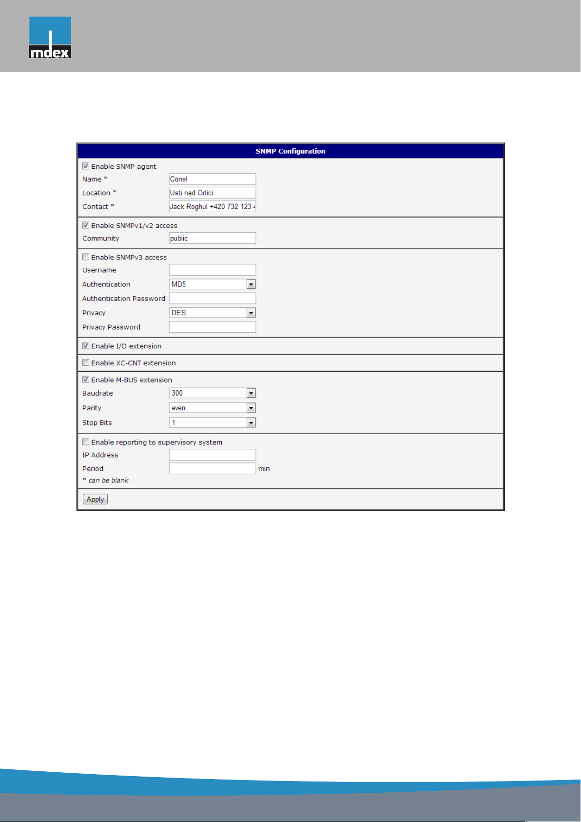
mdex AG • Bäckerbarg 6 • 22889 Tangstedt
Example of SNMP settings and readout:
1. CONFIGURATION OVER WEB
Figure 50: Example of SNMP configuration
69
Page 78
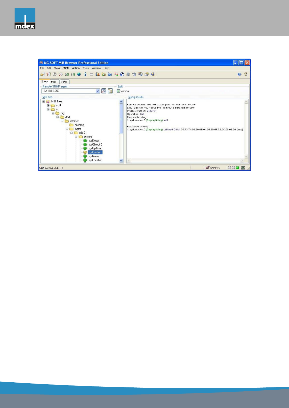
mdex AG • Bäckerbarg 6 • 22889 Tangstedt
1. CONFIGURATION OVER WEB
Figure 51: Example of the MIB browser
It is important to set the IP address of the SNMP agent (router) in field Remote SNMP
agent. After enter the IP address is in a MIB tree part is possible show object identifier.
The path to objects is:
iso → org → dod → internet → private → enterprises → conel → protocols
The path to information about router is:
iso → org → dod → internet → mgmt → mib-2 → system
70
Page 79
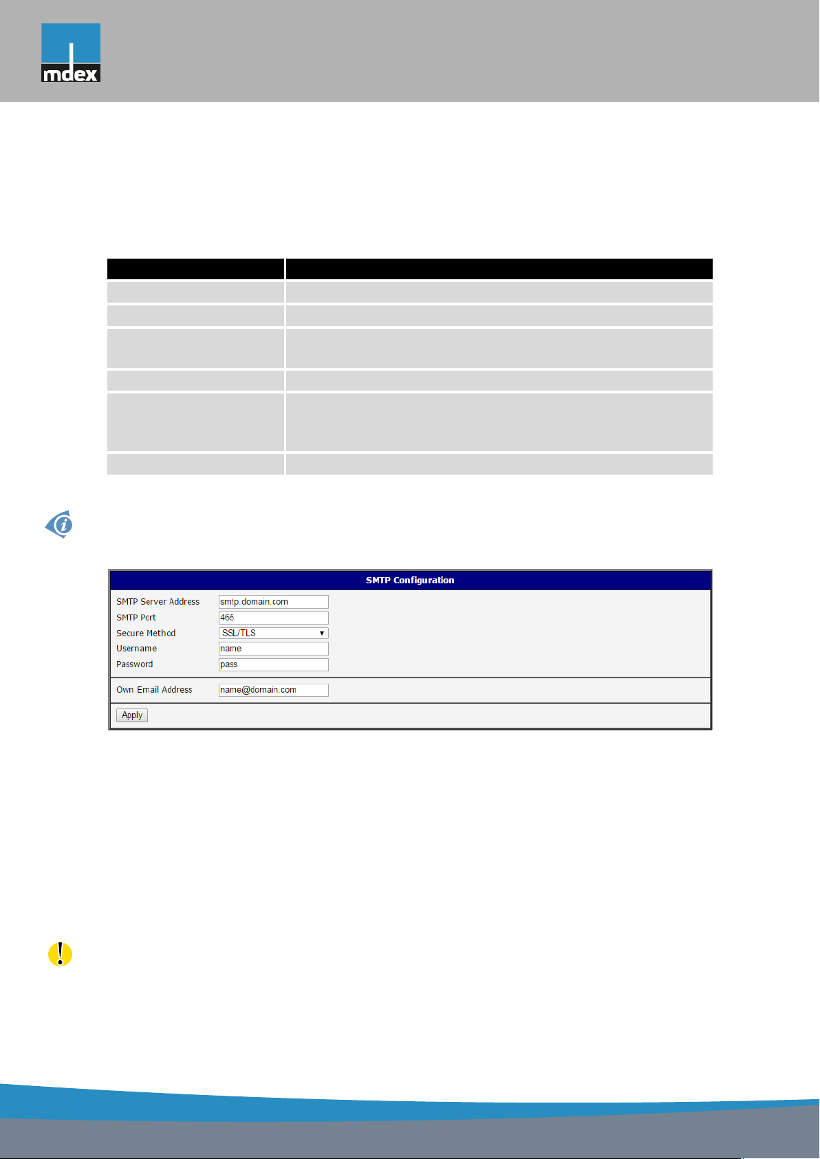
mdex AG • Bäckerbarg 6 • 22889 Tangstedt
1. CONFIGURATION OVER WEB
1.28 SMTP Configuration
The item SMTP is used for configuring SMTP (Simple Mail Transfer Protocol) client for
sending e-mails.
Item Description
SMTP Server Address IP or domain address of the mail server.
SMTP Port Port the SMTP server is listening on
Secure Method none, SSL/TLS, or STARTTLS. Secure method has to be sup-
ported by the SMTP server.
Username Name to e-mail account.
Password Password to e-mail account. Can contain special characters
* + , - . / : = ? ! # % [ ] _ { } ~
and can not contain special characters ? $ & ’ ( ) ; < >
Own E-mail Address Address of the sender.
Table 58: SMTP client configuration
Mobile operator can block other SMTP servers, then you can use only the SMTP server of
operator.
Figure 52: Example of the SMTP client configuration
E-mail can be sent from the Startup script (Startup Script item in the Configuration section)
or via telnet and SSH connection. The command email is can be used with the following
parameters:
-t receiver’s E-mail address
-s subject (has to be in quotation marks)
-m message (has to be in quotation marks)
-a attachment file
-r number of attempts to send email (default 2 attempts set)
Commands and parameters can be entered only in lowercase. Example of sending an e-mail:
71
Page 80

mdex AG • Bäckerbarg 6 • 22889 Tangstedt
1. CONFIGURATION OVER WEB
This command sends e-mail to address [email protected] with the subject "subject",
body message "message" and attachment "abc.doc" right from the directory c:\directory\
and attempts to send 5 times.
1.29 SMS configuration
For mdex Router MX700 the SMS Configuration item is not available.
SMS Configuration can be called up by option SMS item in the menu. SMS configuration
defines the options for sending SMS messages from the router at different defined events and
states of the router. In the first part of window it configuration send SMS.
Item Description
Send SMS on power up Automatic sending of SMS messages after power up.
Send SMS on connect to mobile
network
Send SMS on disconnect to mobile network
Send SMS when datalimit
exceeded
Send SMS when binary input on
I/O port (BIN0) is active
Send SMS when binary input on
expansion port (BIN1 – BIN4) is
active
Add timestamp to SMS Adds time stamp to sent SMS messages. This stamp
Phone Number 1 Telephone numbers for sending automatically gener-
Phone Number 2 Telephone numbers for sending automatically gener-
Phone Number 3 Telephone numbers for sending automatically gener-
Unit ID The name of the router that will be sent in an SMS.
BIN0 – SMS SMS text messages when activate the binary input on
BIN1 – SMS SMS text messages when activate the binary input on
Automatic sending SMS message after connection to
mobile network.
Automatic sending SMS message after disconnection
to mobile network.
Automatic sending SMS message after datalimit exceeded.
Automatic sending SMS message after binary input
on I/O port (BIN0) is active. Text of message is intended parameter BIN0.
Automatic sending SMS message after binary input
on expansion port (BIN1 – BIN4) is active. Text of
message is intended parameter BIN1 – BIN4.
has a fixed format YYYY-MM-DD hh:mm:ss.
ated SMS.
ated SMS.
ated SMS.
the router.
the expansion port.
Continued on next page
72
Page 81

mdex AG • Bäckerbarg 6 • 22889 Tangstedt
1. CONFIGURATION OVER WEB
Continued from previous page
Item Description
BIN2 – SMS SMS text messages when activate the binary input on
the router.
BIN3 – SMS SMS text messages when activate the binary input on
the router.
BIN4 – SMS SMS text messages when activate the binary input on
the router.
Table 59: Send SMS configuration
In the second part of the window it is possible to set function Enable remote control via
SMS. After this it is possible to establish and close connection by SMS message.
Item Description
Phone Number 1 This control can be configured for up to three numbers. If is set
Enable remote control via SMS, all incoming SMS are processed
and deleted. In the default settings this parameter is turned on.
Phone Number 2 This control can be configured for up to three numbers. If is set
Enable remote control via SMS, all incoming SMS are processed
and deleted. In the default settings this parameter is turned on.
Phone Number 3 This control can be configured for up to three numbers. If is set
Enable remote control via SMS, all incoming SMS are processed
and deleted. In the default settings this parameter is turned on.
Table 60: Control via SMS configuration
If no phone number is filled in, then it is possible to restart the router with the help of SMS
in the form of Reboot from any phone number. While filling of one, two or three numbers
it is possible to control the router with the help of an SMS sent only from these numbers.
While filling of sign "*" it is possible control the router with the help of an SMS sent from every
numbers.
Control SMS message doesn?t change the router configuration. If the router is switched
to offline mode by the SMS message the router will be in this mode up to next restart. This
behavior is the same for all control SMS messages.
It is possible to send controls SMS in the form:
SMS Description
go online sim 1 Switch to SIM1 card
go online sim 2 Switch to SIM2 card
73
Continued on next page
Page 82

mdex AG • Bäckerbarg 6 • 22889 Tangstedt
1. CONFIGURATION OVER WEB
Continued from previous page
SMS Description
go online Switch router in online mode
go offline connection termination
set out0=0 Set output I/O connector on 0
set out0=1 Set output I/O connector on 1
set out1=0 Set output expansion port XC-CNT on 0
set out1=1 Set output expansion port XC-CNT on 1
set profile std Set standard profile
set profile alt1 Set alternative profile 1
set profile alt2 Set alternative profile 2
set profile alt3 Set alternative profile 3
reboot Router reboot
get ip Router send answer with IP address SIM card
Table 61: Control SMS
By choosing Enable AT-SMS protocol on expansion port 1 and Baudrate it is possible to
send/receive an SMS on the serial Port 1.
Item Description
Baudrate Communication speed expansion port 1
Table 62: Send SMS on serial PORT1 configuration
By choosing Enable AT-SMS protocol on expansion port 2 and Baudrate it is possible to
send/receive an SMS on the serial Port 2.
Item Description
Baudrate Communication speed expansion port 2
Table 63: Send SMS on serial PORT2 configuration
By choosing Enable AT-SMS protocol on TCP port and enter the TCP port it is possible to
send/receive an SMS on the TCP port. SMS messages are sent by the help of a standard AT
commands.
Item Description
TCP Port TCP port on which will be allowed to send/receive SMS messages.
Table 64: Send SMS on ethernet PORT1 configuration
74
Page 83

mdex AG • Bäckerbarg 6 • 22889 Tangstedt
1. CONFIGURATION OVER WEB
1.29.1 Send SMS
After establishing connection with the router via serial interface or Ethernet, it is possible
to use AT commands for work with SMS messages.
The following table only lists the commands that are supported by MX7 Series routers.
For other AT commands is always sent OK response. There is no support for treatment of
complex AT commands, so in such a case router sends ERROR response.
AT Command Description
AT+CGMI Returns the manufacturer specific identity
AT+CGMM Returns the manufacturer specific model identity
AT+CGMR Returns the manufacturer specific model revision identity
AT+CGPADDR Displays the IP address of the ppp0 interface
AT+CGSN Returns the product serial number
AT+CIMI Returns the International Mobile Subscriber Identity number (IMSI)
AT+CMGD Deletes a message from the location
AT+CMGF Sets the presentation format of short messages
AT+CMGL Lists messages of a certain status from a message storage area
AT+CMGR Reads a message from a message storage area
AT+CMGS Sends a short message from the device to entered tel. number
AT+CMGW Writes a short message to SIM storage
AT+CMSS Sends a message from SIM storage location value
AT+COPS? Identifies the available mobile networks
AT+CPIN Is used to query and enter a PIN code
AT+CPMS Selects SMS memory storage types, to be used for short message
operations
AT+CREG Displays network registration status
AT+CSCA Sets the short message service centre (SMSC) number
AT+CSCS Selects the character set
AT+CSQ Returns the signal strength of the registered network
AT+GMI Returns the manufacturer specific identity
AT+GMM Returns the manufacturer specific model identity
AT+GMR Returns the manufacturer specific model revision identity
AT+GSN Returns the product serial number
ATE Determines whether or not the device echoes characters
ATI Transmits the manufacturer specific information about the device
Table 65: List of AT commands
75
Page 84
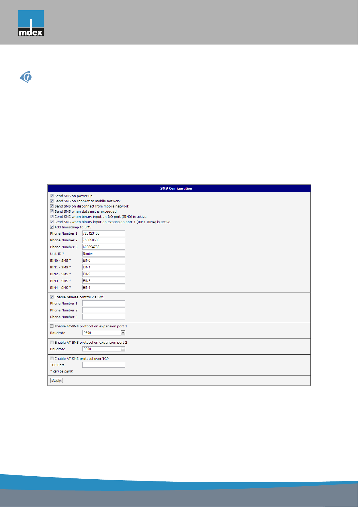
mdex AG • Bäckerbarg 6 • 22889 Tangstedt
1. CONFIGURATION OVER WEB
A detailed description and examples of these AT commands can be found in the application
note AT commands.
After powering up the router, at the mentioned the phone number comes SMS in this form:
Router (Unit ID) has been powered up. Signal strength ?xx dBm.
After connect to mobile network, at the mentioned phone number comes SMS in this form:
Router (Unit ID) has established connection to mobile network. IP address xxx.xxx.xxx.xxx
After disconnect to mobile network, at the mentioned phone number comes SMS in this form:
Router (Unit ID) has lost connection to mobile network. IP address xxx.xxx.xxx.xxx
Configuration of sending this SMS is following:
Figure 53: Example of SMS configuration 1
76
Page 85
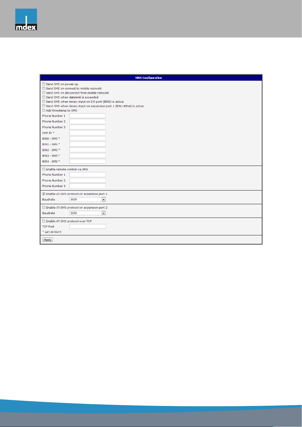
mdex AG • Bäckerbarg 6 • 22889 Tangstedt
1. CONFIGURATION OVER WEB
Example of the router configuration for SMS sending via serial interface on the PORT1:
Figure 54: Example of SMS configuration 2
77
Page 86
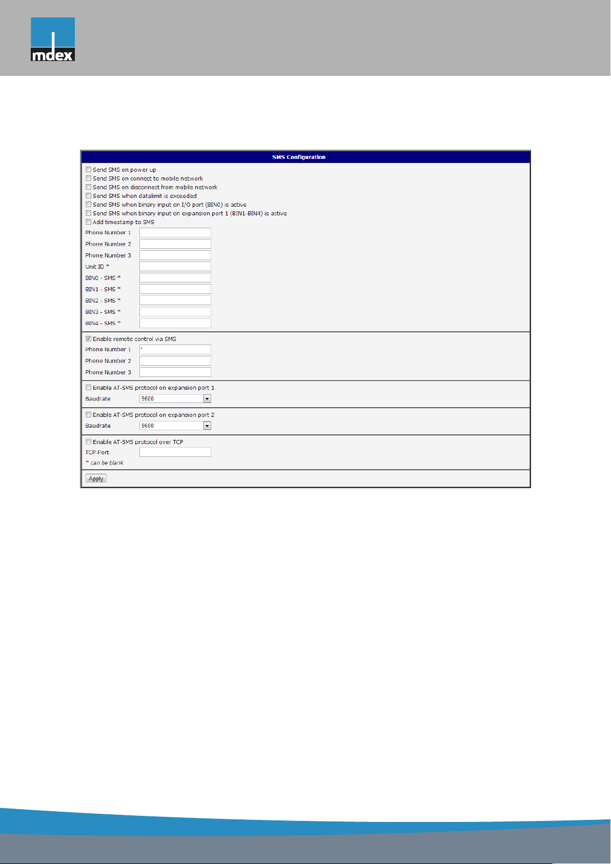
mdex AG • Bäckerbarg 6 • 22889 Tangstedt
1. CONFIGURATION OVER WEB
Example of the router configuration for controlling via SMS from every phone numbers:
Figure 55: Example of SMS configuration 3
78
Page 87
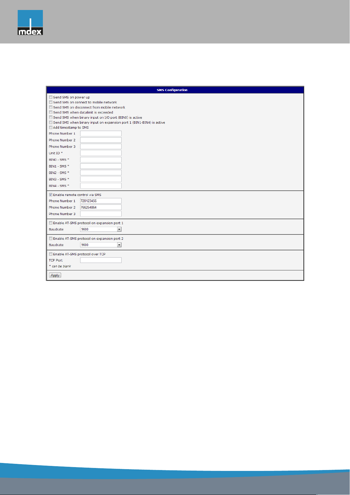
mdex AG • Bäckerbarg 6 • 22889 Tangstedt
1. CONFIGURATION OVER WEB
Example of the router configuration for controlling via SMS from two phone numbers:
Figure 56: Example of SMS configuration 4
79
Page 88

mdex AG • Bäckerbarg 6 • 22889 Tangstedt
1. CONFIGURATION OVER WEB
1.30 Expansion port configuration
Configuring of the expansion ports PORT1 and PORT2 can cause selecting Expansion
Port 1 or Expansion Port 2.
Item Description
Baudrate Applied communication speed.
Data Bits Number of data bits.
Parity Control parity bit
• none – will be sent without parity
• even – will be sent with even parity
• odd – will be sent with odd parity
Stop Bits Number of stop bit.
Split Timeout Time to rupture reports. If you receive will identify the gap between two
characters, which is longer than the parameter value in milliseconds.
Then all of the received data compiled and sent the message.
Protocol Protocol:
• TCP – communication using a linked protocol TCP
• UDP – communication using a unlinked protocol UDP
Mode Mode of connection:
• TCP server – router will listen to incoming requests about TCP
connection
• TCP client – router will connect to a TCP server on the specified
IP address and TCP port
Server Address In mode TCP client it is necessary to enter the Server address and
final TCP port.
TCP Port In both modes of connection is necessary to specify the TCP port on
which the router will communicate TCP connections.
Inactivity Timeout Time period after which the TCP/UDP connection is interrupted in case
of inactivity
Table 66: Expansion PORT configuration 1
If the Reject new connections item is ticked, all other connections are rejected. This means
that it is not possible to establish multiple connections.
80
Page 89

mdex AG • Bäckerbarg 6 • 22889 Tangstedt
1. CONFIGURATION OVER WEB
After check Check TCP connection, it activates established of TCP connection.
Item Description
Keepalive Time Time, after which it will carry out verification of the connection
Keepalive Interval Waiting time on answer
Keepalive Probes Number of tests
Table 67: Expansion PORT configuration 2
When you select items Use CD as indicator of the TCP connection is activated function
indication TCP connection using signal CD (DTR on the router).
CD Description
Active TCP connection is on
Nonactive TCP connection is off
Table 68: CD signal description
When you select items Use DTR as control of TCP connection is activated function control
TCP connection using signal DTR (CD on the router).
DTR Description server Description client
Active The router allows establishing a TCP
connection
Nonactive The router does not permit establishing
a TCP connection
Table 69: DTR signal description
The changes in settings will apply after pressing the Apply button.
Router starts TCP connection
Router stops TCP connection
81
Page 90
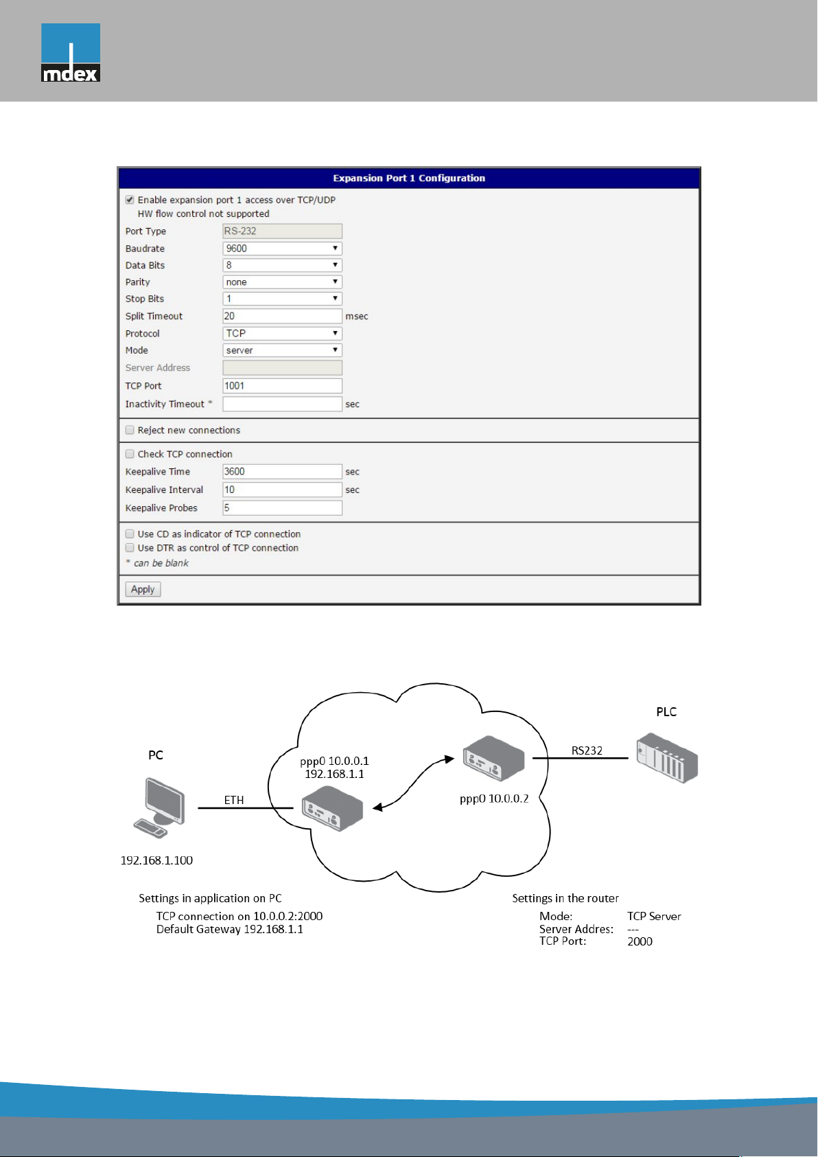
mdex AG • Bäckerbarg 6 • 22889 Tangstedt
1. CONFIGURATION OVER WEB
Figure 57: Expansion port configuration
Example of external port configuration:
Figure 58: Example of expansion port configuration 1
82
Page 91
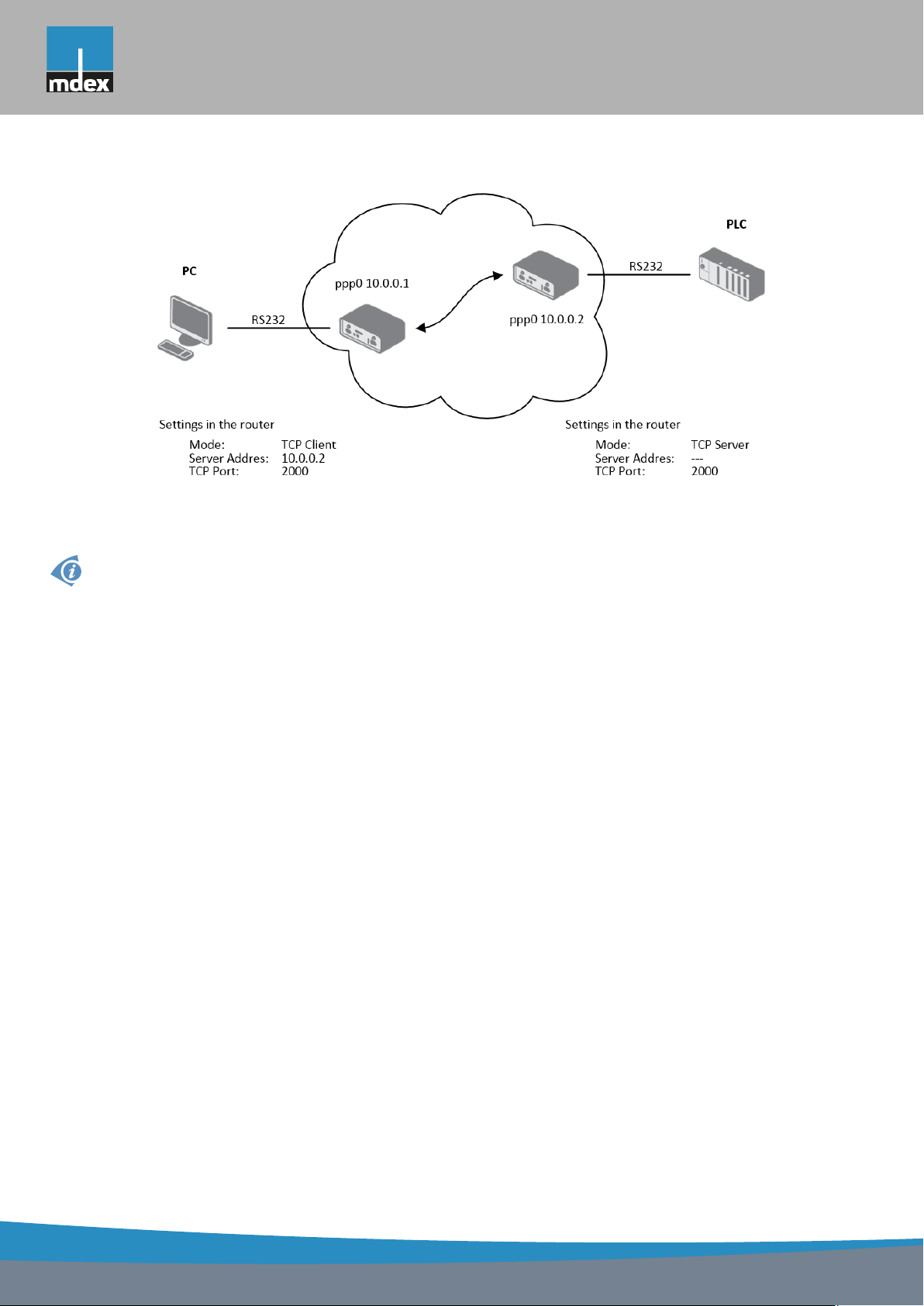
mdex AG • Bäckerbarg 6 • 22889 Tangstedt
1. CONFIGURATION OVER WEB
Figure 59: Example of expansion port configuration 2
Since firmware 3.0.9 all MX7 Series routers provide a program called getty which allows
user to connect to the router via the serial line (router must be fitted with an expansion port
RS232!). Getty displays the prompt and after entering the username passes it on login program, which asks for a password, verifies it and runs the shell. After logging in, it is possible
to manage the system as well as a user is connected via telnet.
83
Page 92

mdex AG • Bäckerbarg 6 • 22889 Tangstedt
1. CONFIGURATION OVER WEB
1.31 USB port configuration
The USB port configuration can be called up by airbrush option USB Port in menu. Configuration can be done, if we have USB/RS232 converter.
Item Description
Baudrate Applied communication speed.
Data Bits Number of data bits.
Parity Control parity bit:
• none – will be sent without parity
• even – will be sent with even parity
• odd – will be sent with odd parity
Stop Bits Number of stop bit.
Split Timeout Time to rupture reports. If you receive will identify the gap between
two characters, which is longer than the parameter value in milliseconds. Then all of the received data compiled and sent the message.
Protocol Communication protocol:
• TCP – communication using a linked protocol TCP
• UDP – communication using a unlinked protocol UDP
Mode Mode of connection:
• TCP server – router will listen to incoming requests about TCP
connection
• TCP client – router will connect to a TCP server on the speci-
fied IP address and TCP port
Server Address In mode TCP client it is necessary to enter the Server address and
final TCP port.
TCP Port In both modes of connection is necessary to specify the TCP port on
which the router will communicate TCP connections.
Inactivity Timeout Time period after which the TCP/UDP connection is interrupted in
case of inactivity
Table 70: USB port configuration 1
If the Reject new connections item is ticked, all other connections are rejected. This means
that it is not possible to establish multiple connections.
84
Page 93

mdex AG • Bäckerbarg 6 • 22889 Tangstedt
1. CONFIGURATION OVER WEB
After check Check TCP connection, it activates verification of established TCP connection.
Item Description
Keepalive Time Time, after which it will carry out verification of the connection
Keepalive Interval Waiting time on answer
Keepalive Probes Number of tests
Table 71: USB PORT configuration 2
When you select items Use CD as indicator of the TCP connection is activated function
indication TCP connection using signal CD (DTR on the router).
CD Description
Active TCP connection is on
Nonactive TCP connection is off
Table 72: CD signal description
When you select items Use DTR as control of TCP connection is activated function control
TCP connection using signal DTR (CD on the router).
DTR Description server Description client
Active The router allows establishing a TCP
connection
Nonactive The router does not permit establishing
a TCP connection
Table 73: DTR signal description
Supported USB/RS232 converters:
• FTDI
• Prolific PL2303
• Silicon Laboratories CP210×(supported from firmware version 3.0.1)
The changes in settings will apply after pressing the Apply button
Router starts TCP connection
Router stops TCP connection
85
Page 94
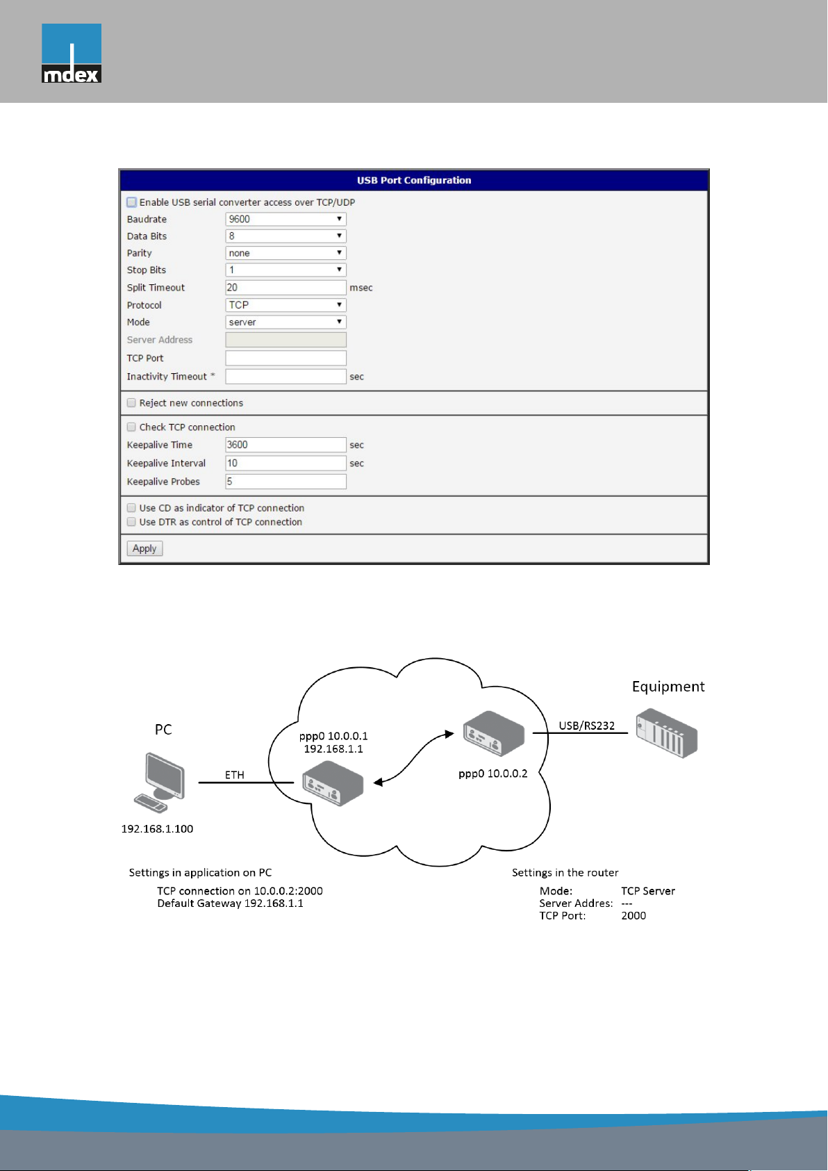
mdex AG • Bäckerbarg 6 • 22889 Tangstedt
1. CONFIGURATION OVER WEB
Figure 60: USB configuration
Example of USB port configuration:
Figure 61: Example of USB port configuration 1
86
Page 95
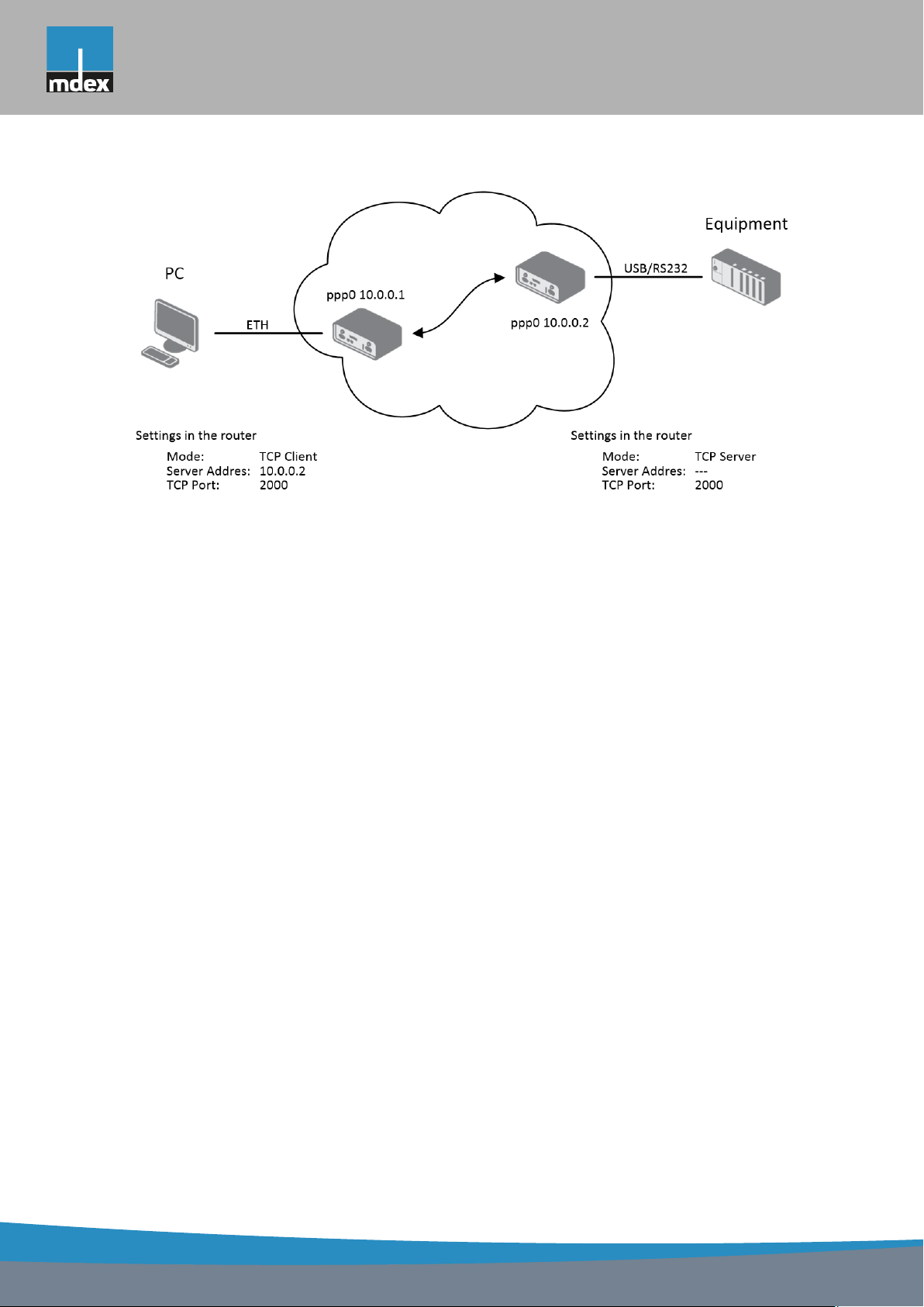
mdex AG • Bäckerbarg 6 • 22889 Tangstedt
1. CONFIGURATION OVER WEB
Figure 62: Example of USB port configuration 2
87
Page 96
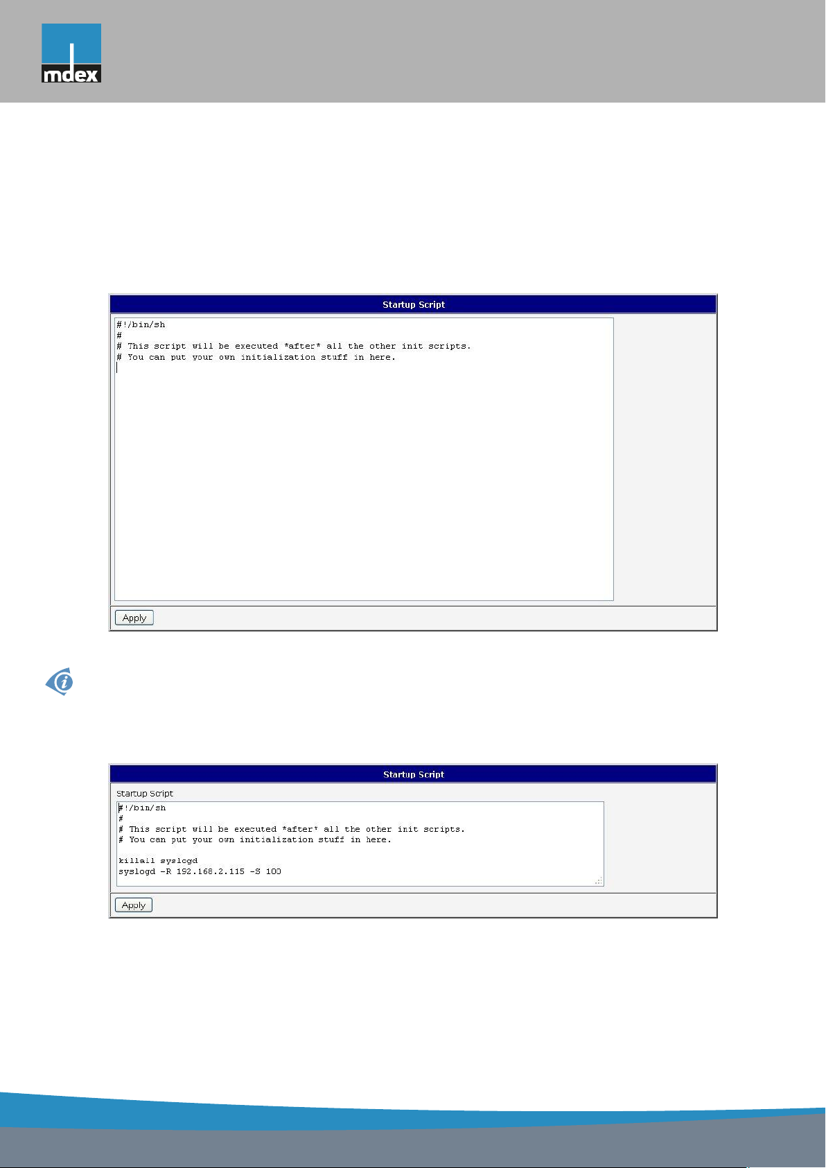
mdex AG • Bäckerbarg 6 • 22889 Tangstedt
1. CONFIGURATION OVER WEB
1.32 Startup script
In the window Startup Script it is possible to create own scripts which will be executed after
all initial scripts.
The changes in settings will apply after pressing the Apply button.
Figure 63: Startup script
Change take effect after shut down and witch on router by the help of button Reboot in
web administration or by SMS message.
Example of Startup script: When start the router, stop syslogd program and start syslogd
with remote logging on address 192.168.2.115 and limited to 100 entries listing.
Figure 64: Example of Startup script
88
Page 97
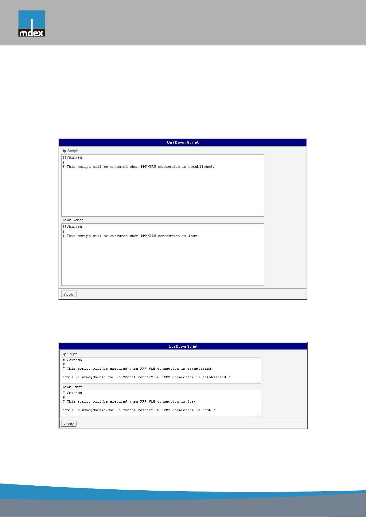
mdex AG • Bäckerbarg 6 • 22889 Tangstedt
1. CONFIGURATION OVER WEB
1.33 Up/Down script
In the window Up/Down Script it is possible to create own scripts. In the item Up script
is defined scripts, which begins after establishing a PPP/WAN connection. In the item Down
Script is defines script, which begins after lost a PPP/WAN connection.
The changes in settings will apply after pressing the Apply button.
Figure 65: Up/Down script
Example of UP/Down script: After establishing or lost a connection, the router sends an
email with information about establishing or loss a connection.
Figure 66: Example of Up/Down script
89
Page 98

mdex AG • Bäckerbarg 6 • 22889 Tangstedt
1. CONFIGURATION OVER WEB
1.34 Automatic update configuration
In the Automatic update item it is possible to set the automatic configuration update. This
choice enables the router to download the configuration and the newest firmware from the
server automatically. The configuration and firmware files are stored on the server. To prevent
possible unwanted manipulation of the files, downloaded file (tar.gz format) is controlled. At
first, the format of the downloaded file is checked. Then the type of architecture and each file
in the archive (tar.gz file) is controlled.
By Enable automatic update of configuration it is possible to enable automatic configuration
update.
By Enable automatic update of firmware it is possible to enable firmware update.
Item Description
Source Where the router will download the firmware and configuration from:
• HTTP(S)/FTP(S) server – updates are downloaded from the
Base URL address below. Used protocol is specified by that address: HTTP, HTTPS, FTP or FTPS.
• USB flash drive – Router finds current firmware or configuration
in the root directory of the connected USB device.
• Both – looking for the current firmware or configuration from both
sources.
Base URL Enter the base part of the domain or IP address to download the up-
dates from. Specify the communication protocol by the address (HTTP,
HTTPS, FTP or FTPS).
Unit ID Name of configuration (name of the file without extension). If the Unit
ID is not filled, the MAC address of the router is used as the filename
(the delimiter colon is used instead of a dot.)
Update Hour Use this item to set the hour (range 1-24) when the automatic update
will be performed every day. If the time is not specified, automatic
update is performed five minutes after turning on the router and then
every 24 hours. If the detected configuration file is different from the
running one, it is downloaded and the router is restarted automatically
to make it run.
Table 74: Automatic update configuration
The configuration file name is from parameter Base URL, hardware MAC address of ETH0
interface and cfg extension. Hardware MAC address and cfg extension is connected automatically and it isn?t needed to enter this. By parameter Unit ID enabled it defines the concrete
configuration name which will be download to the router. When using parameter Unit ID,
hardware MAC address in configuration name will not be used.
The firmware file name is from parameter Base URL, type of router and bin extension.
90
Page 99
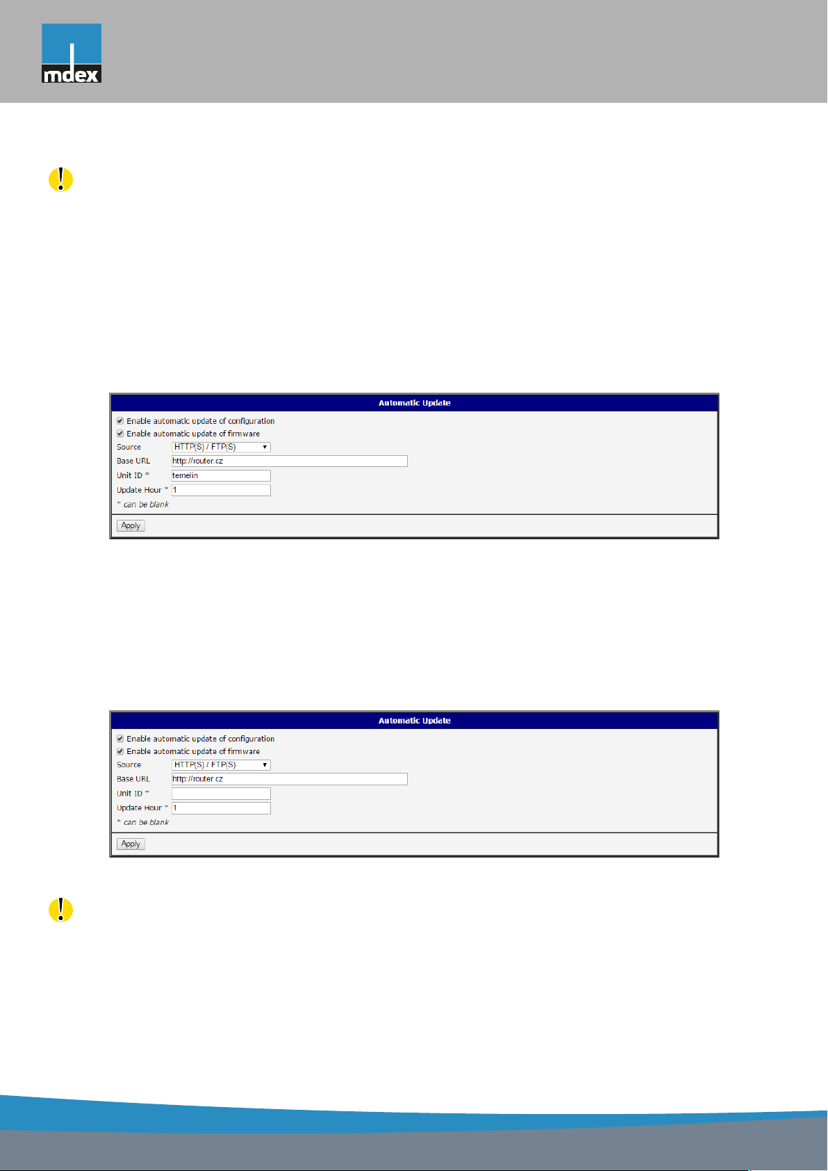
mdex AG • Bäckerbarg 6 • 22889 Tangstedt
1. CONFIGURATION OVER WEB
It is necessary to load two files (.bin and .ver) to the HTTP(S)/FTP(S) server. If there
is uploaded only the .bin file and the HTTP server send wrong answer 200 OK (instead of
expected 404 Not Found) when the device try to download the nonexistent .ver file, then there
is a high risk that the router will download the .bin file over and over again.
The following examples find if there is a new firmware or configuration each day at 1:00 in
the morning. The following example is for the MX720 type of router.
• Firmware: http://router.cz/ER75i-v2.bin
• Configuration file: http://router.cz/temelin.cfg
Figure 67: Example of automatic update 1
The following examples find if there is a new firmware or configuration each day at 1:00 in
the morning. The following example is for MX720 with MAC address 00:11:22:33:44:55.
• Firmware: http://router.cz/ER75i-v2.bin
• Configuration file: http://router.cz/00.11.22.33.44.55.cfg
Figure 68: Example of automatic update 2
Firmware update can cause incompatibility of the user modules. It is recommended to
update user modules to the most recent version. Information about the user module and the
firmware compatibility is at the beginning of the user module’s Application Note.
91
Page 100
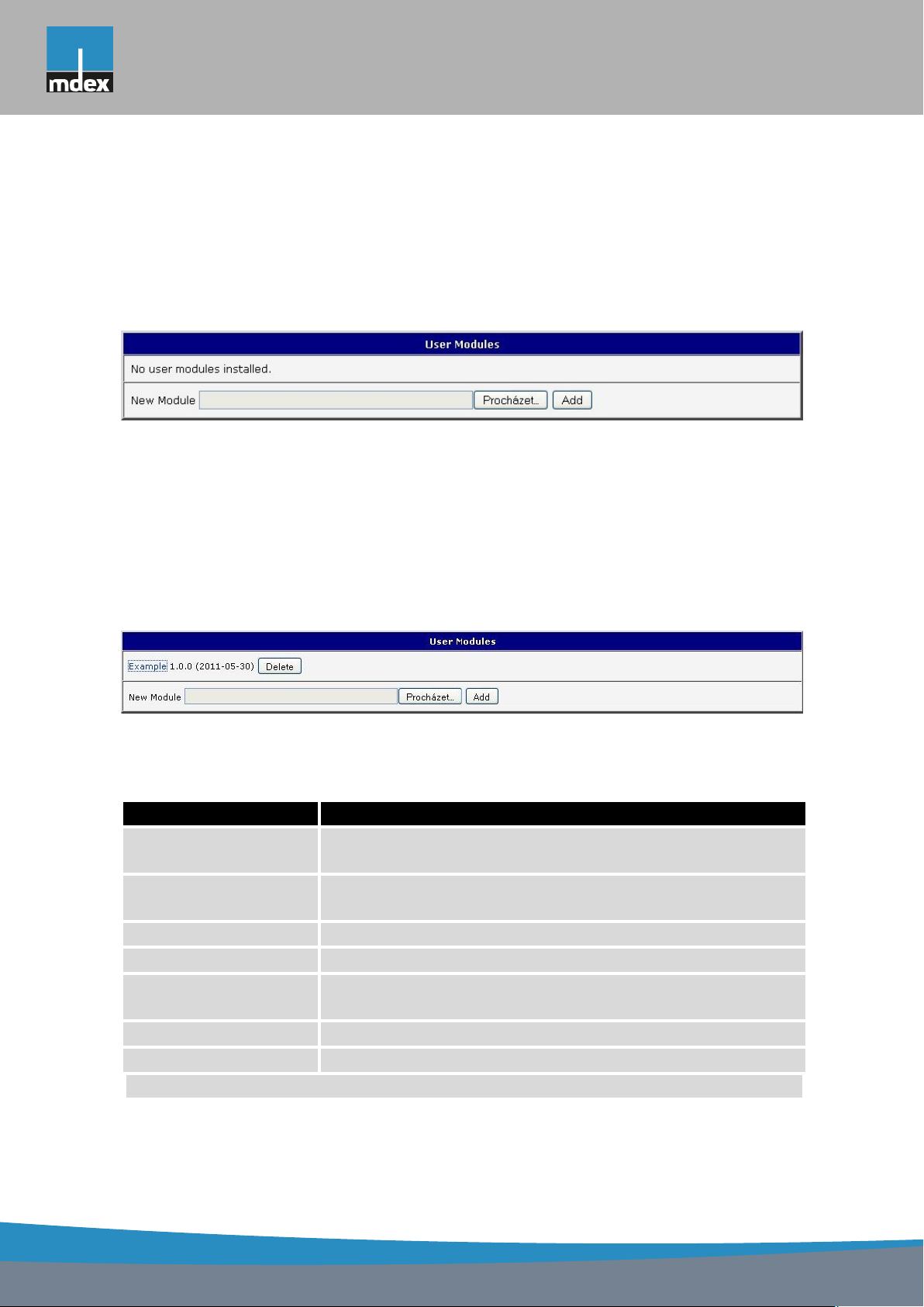
mdex AG • Bäckerbarg 6 • 22889 Tangstedt
1. CONFIGURATION OVER WEB
1.35 User modules
Configuration of user modules can be accessed by selecting the User Modules item. It is
possible to add new modules, delete them or switch to their configuration. Use the Browse
button to select the user module (compiled module has tgz extension). The module is added
using the Add button.
Figure 69: User modules
Added module appears in the list of modules on the same page. If the module contains
index.html or index.cgi page, module name serves as a link to this page. The module can be
deleted using the Delete button.
Updating of the module can be done in the same way like adding a new module. Module
with a higher (newer) version will replace the existing module. The current module configuration is kept in same state.
Programming and compiling of modules are described in the programming guide.
Figure 70: Added user module
There are for example these user’s modules:
Module name Description
MODBUS TCP2RTU Provides a conversion of MODBUS TCP/IP protocol to MDBUS
RTU protocol, which can be operated on the serial line.
Easy VPN client Provides secure connection of LAN network behind our router
with LAN network behind CISCO router.
NMAP Allows to do TCP and UDP scan.
Daily Reboot Allows to perform daily reboot of the router at the specified time.
HTTP Authentication Adds the process of authentication to a server that doesn’t pro-
vide this service.
BGP, RIP, OSPF Add support of dynamic protocols.
PIM SM Adds support of multicast routing protocol PIM-SM.
Continued on next page
92
 Loading...