

MD mxion ssm User Manual
SSM Bedienungsanleitung
SSM User manual

2 SSM
Einleitende Information Introduction
Sehr geehrte Kunden, wir empfehlen Dear customer, we strongly
die Produktdokumentation und vor recommend that you read these
allem auch die Warnhinweise vor der manuals and the warning notes
Inbetriebnahme gründlich zu lesen und thouroughly before installing and
diese zu Beachten. Das Produkt ist kein operating your device. The device
Spielzeug (15+). is not a toy (15+).
HINWEIS: Vergewissern Sie sich, ob die NOTE: Make sure that the outputs
Ausgangsspannungen zu ihrem Verbrauch- are set to appropriate value
er passen, da dieser sonst zerstört werden before hooking up any other
kann! Für Nichtbeachtung übernehmen wir device. MD can’t be responsible
keine Haftung. For any damage if this is
disregarded.
HINWEIS: Funktionsausgang A3

3 SSM
Inhaltsverzeichnis Table of Contents
Grundlegende Informationen General information 4
Funktionsumfang Summary of functions 5
Lieferumfang Scope of supply 6
Inbetriebnahme Hook-Up 7
Anschlussbuchsen Connectors 8
Anschluss für Pufferspeicher Connection for Buffer 11
Produktbeschreibung Product description 12
Fahrstufen Steedsteps 13
Fahrkurven Speed curves 13
Rangiergang Switching speed 15
Anfahr-/Bremsverzögerung Acceleration and Deceleration 15
Abschaltbare Verzögerungszeiten Switchable delay times 15
Fahrstufen Steedsteps 15
Kontakteingänge Contact inputs 16
Servofunktion Servo function 16
Pufferbetrieb Buffer operation 17
Analogbetrieb Analog operation 17
IntelliSound-Support IntelliSound-Support 18
Programmiersperre Programming lock 19
Programmiermöglichkeiten Programming options 19
Programmierung von binären Werten Programming binary values 20
Programmierung Lokadressen Programming loco adress 21
Resetfunktionen Reset functions 21
Merkmale der Funktionsausgänge Function output features 22
CV-Tabelle CV-Table 24
Technische Daten Technical data 32
Garantie, Reparatur Warranty, Service, Support 33
Hotline Hotline 34

4 SSM
Grundlegende Informationen General information
Wir empfehlen die Anleitung gründlich We recommend studying this manual
zu lesen, bevor Sie Ihr neues Gerät in thoroughly before installing and
Betrieb nehmen. operating your new device.
Bauen Sie das Modul an einem geschützten Place the decoder in a protected location.
Platz ein. Schützen Sie es vor andauernder The unit must not be exposed to moisture.
Feuchtigkeit.
HINWEIS: Einige Funktionen sind nur mit NOTE: Some funktions are only
der neusten Firmware nutzbar, führen available with the latest firmware.
Sie daher bei Bedarf ein Update durch. Please make sure that your device
is programmed with the latest
firmware.

5 SSM
Funktionsumfang Summary of Funktions
▪ DC/AC/DCC Betrieb DC/AC/DCC operation
▪ Vollkompatibles NMRA-DCC Modul Compatible NMRA-DCC module
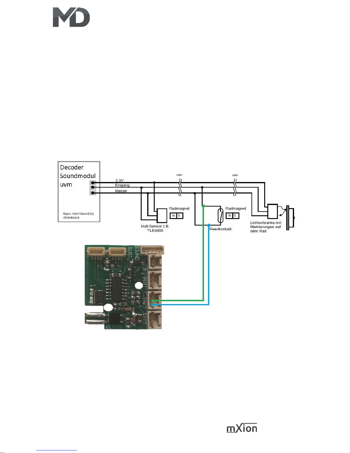
▪ 2 Kontakteingänge für Soundauslösung 2 contact inputs sound switches
▪ SUSI Bus SUSI Bus
▪ REED-Kontakteingänge REED contact inputs
▪ Externer Takteingang External clock
▪ Potianschluss mit Simulation für IntelliSound Poti connection with simulation for IS4
▪ Unterschiedliche Gesch. für Vor- und Rückwärts Differend forward and backward speeds
▪ Funktionsausgang Function output
▪ Viele Sonder- und Zeitfunktionen einstellbar Lot of special and time functions available
▪ Servofunktion Servo functionality
▪ 23 Lichteffekte auf allen Ausgängen 23 light effects on all outputs
▪ Funktionsausgänge dimmbar Function outputs dimmable
▪ Resetfunktionen für alle CVs Reset function for all CV values
▪ Sehr einfaches Funktionsmapping Easy function mapping
▪ Taktsimulation Clock simulation
▪ 28 Funktiontasten adressierbar, 10239 Lokadressen 28 function keys programmable, 10239 loco
▪ 14, 28, 128 Fahrstufen (automatisch) 14, 28, 128 speed steps (automaticly)
▪ Vielfältige Programmiermöglichkeiten Multiple programming options
(Bitweise, CV, POM Schaltdecoder, Register) (Bitwise, CV, POM accessoire decoder register)
▪ Keine Last bei Programmierung erforderlich Needs no programming load
▪ IntelliSound Vollsupport (Poti, REED, Takt, usw) IntelliSound support (poti, reed, clock, etc…)
▪ Analog und digitalfähig mit Geschwindigkeits- Analog and digital support with speed output
ausgabe auf SUSI-Bus auch im analogen on SUSI-Bus also in analoge (SSM + IS4 have a
(➔ mit bspw. IntelliSound 4 vollwertiges full analoge sound module).
Analogsoundmodul mit Standgeräusch,
Brems- und Anfahrgeräusch, Rollgeräusch uvm.)

6 SSM
Lieferumfang Scope of supply
▪ Bedienungsanleitung Manual
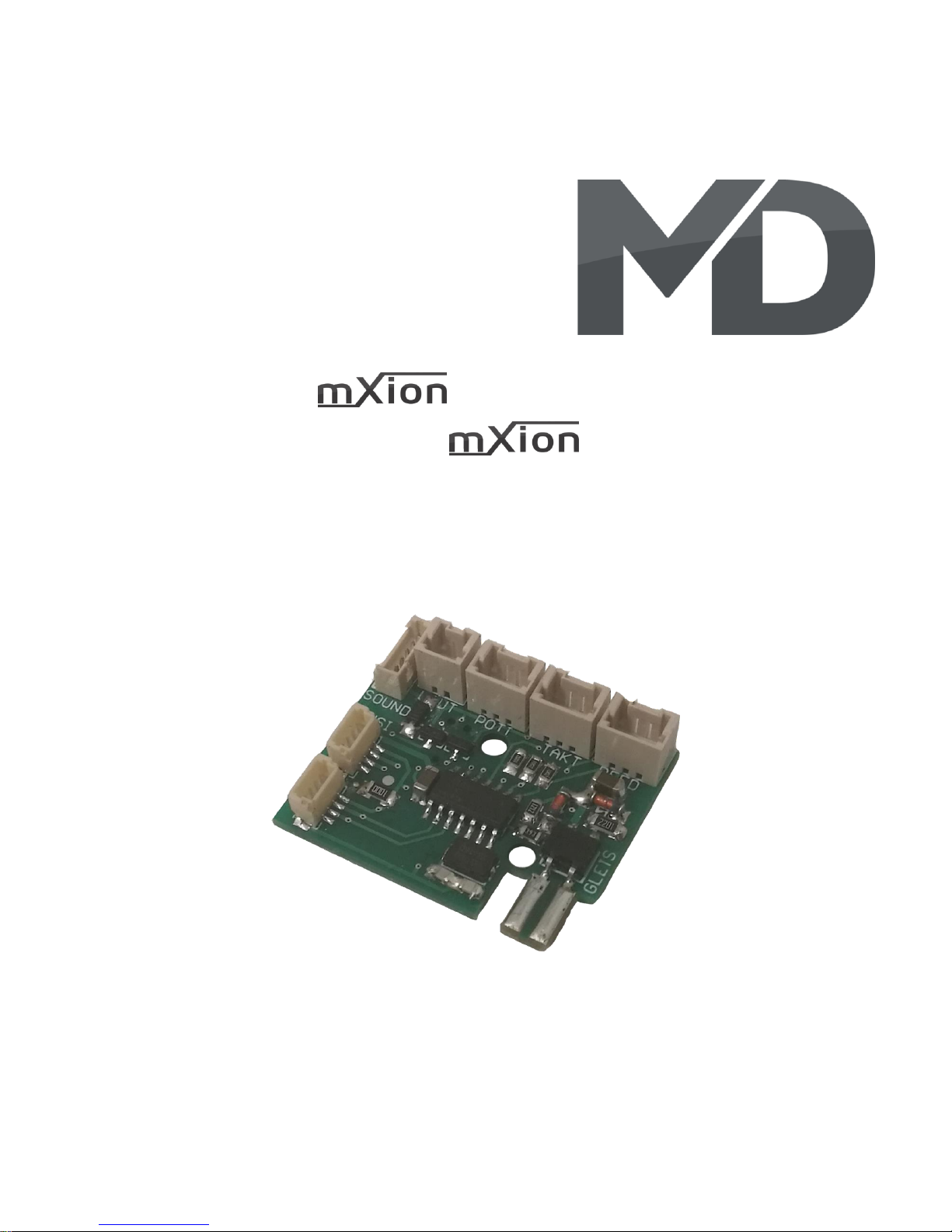
▪ mXion SSM mXion SSM

7 SSM
Inbetriebnahme Hook-Up
Bauen bzw. platzieren Sie Ihr Install your device in compliance with
Gerät sorgfältig nach den Plänen the connecting diagrams in this manual.
dieser Bedienungsanleitung. The device is protected against shorts and
Die Elektronik ist generell gegen excessive loads. However, in case of a
Kurzschlüsse oder Überlastung connection error e.g. a short this safety
gesichert, werden jedoch Kabel feature can’t work and the device will be
vertauscht oder kurzgeschlossen destroyed subsequently.
kann keine Sicherung wirken und Make sure that there is no short circuit
das Gerät wird dadurch ggf. zerstört. caused by the mounting screws or metal.
Achten Sie ebenfalls beim befestigen
darauf, dass kein Kurzschluss mit
Metallteilen entsteht.
HINWEIS: Bitte beachten Sie die NOTE: Please note the CV basic settings
CV-Grundeinstellungen im Auslieferungszustand. in the delivery state.
HINWEIS: TAKT ist Eingang und Ausgang zugleich. NOTE: TAKT is input and output at
Wenn CV49 Bit 1 = 0 (ext. Takt) dann ist die TAKT the same time.
Buchse der Takteingang (von Verdampfern, IF CV49 Bit 1 = 0 (external clock) then the
Getriebe, Decoder, o.ä.). clock is book of the clocks (by vaporizers,
Ist CV49 Bit 1 = 1 (interner Takt) wird an der TAKT transmissions, decoders or similar).
Buchse der simulierte Takt zzgl. ausgegeben. IF CV49 Bit 1 = 1 (internal clock) is at the clock
book the simulated measure plus given.
8 SSM
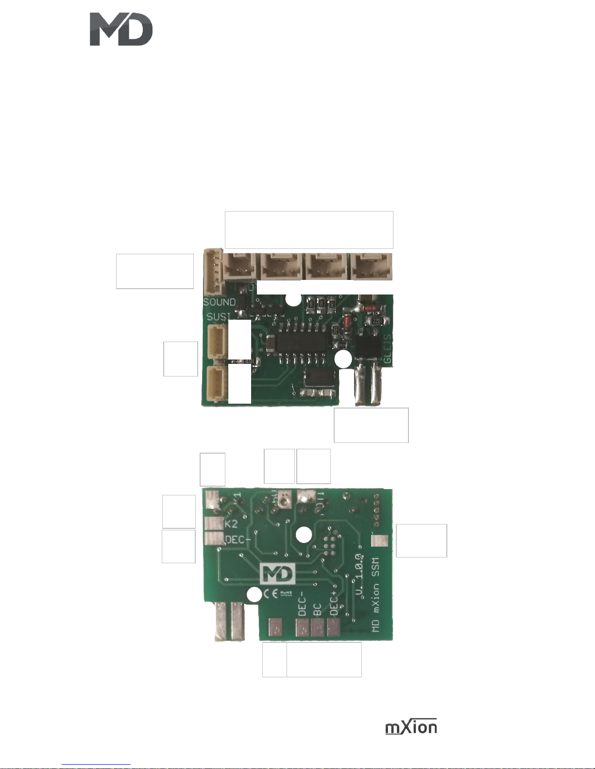
Anschlussbuchsen Connectors
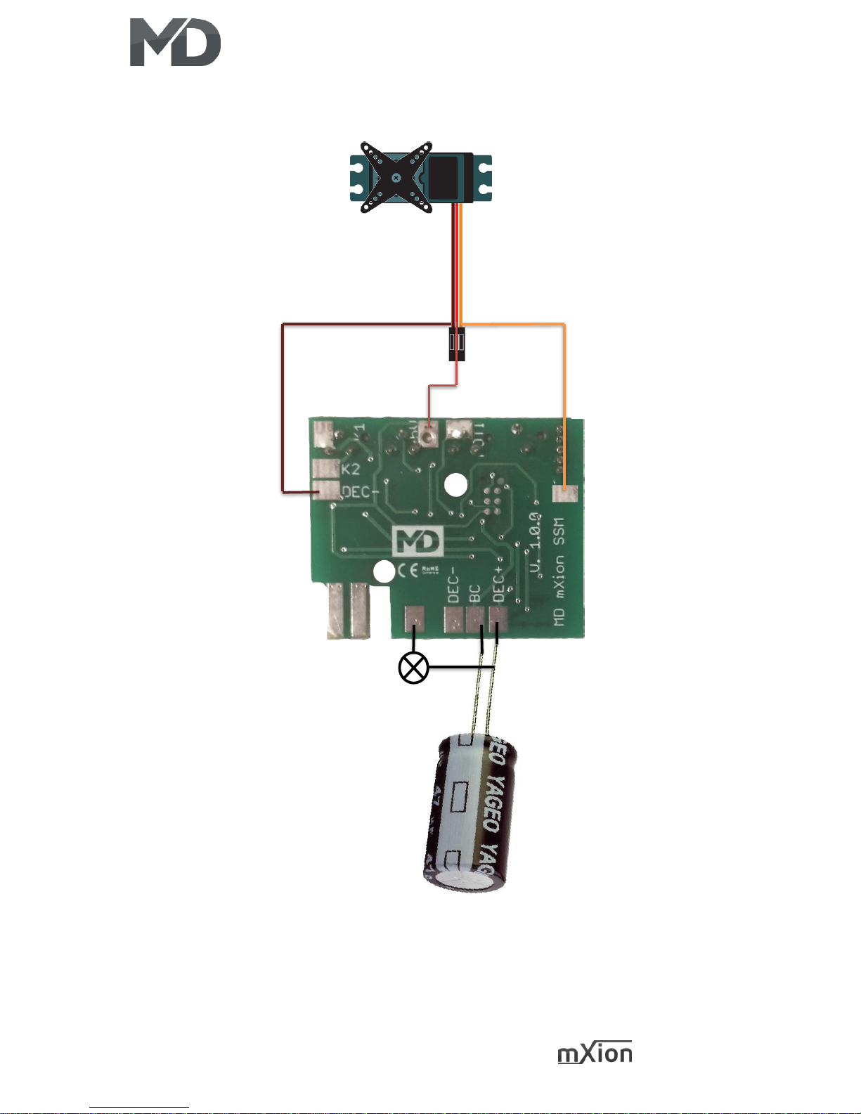
Schalten Sie Verbraucher zwischen A1/F1 und Switch loads between A1/F1 and
gemeinsamen + Pol (DEC+). Bei Verwendung eines common + pole. For servos, use +5V, DEC-
Servos nutzen Sie +5V, DEC- und A1 Servo. and A1 Servo. With this, it’s easy to use a
Damit können Sie problemlos Servos betreiben. servo with this module.
Gleisanschluss
Track input
LAUTSPR POTI TAKT REED
SPEAKER POTI TAKT REED
SUSI
SUSI
IS4-Zusatzkabel
IS4-Cable
+5V
+5V
POTI
POTI
A1
A1
GND|BC|+24V
GND|BC|+24V
GND
GND
K2
K2
K1
K1
A1 Servo
A1 Servo
+5V|POTI|GND
+5V|TAKT|GND
K1|GND|K2
DEC+
TAKT
DATEN
GND
DEC+
TAKT
DATEN
GND
9 SSM
Die Taktbuchse ist Eingang bei externem Takt (CV 49 Bit 1 = 0) oder Ausgang
bei Taktsimulation (CV 49 Bit 1 = 1).
The TAKT plug is input if externally clock (CV 49 Bit 1 = 0) or output if clock
simulation (CV 49 Bit 1 = 1).
10 SSM
11 SSM
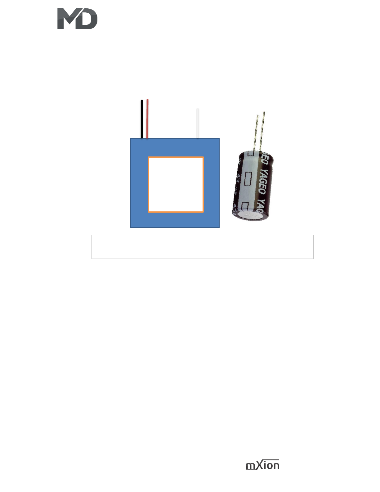
Anschluss für Pufferspeicher Connection for Buffer
Powercap ODER Kondensator (ab 1000 µF Diode/Widerstand (120 Ohm) nutzen)
Powercap or normally cap (above 1000 µF Diode/Resistor (120 Ohm) use)
Powercap
Powercap
DEC+
GND
DEC+
BC
BC
 Loading...