


PELLET STOVES
INSTALLATION AND USE MANUAL
Index
page
1
INTRODUCTION ....................................................................................................................................3
1. WARNINGS AND GUARANTEE CONDITIONS.....................................................................................5
1.1. SAFETY WARNINGS........................................................................................................................5
1.2. OPERATING WARNINGS..................................................................................................................6
1.3. GUARANTEE CONDITIONS ..............................................................................................................7
1.3.1. Limitations...............................................................................................................................7
1.3.2. Exclusions................................................................................................................................7
2. THEORETICAL NOTIONS ON INSTALLATION....................................................................................9
2.1. PELLETS ........................................................................................................................................9
2.2. PRINCIPLES OF OPERATION ..........................................................................................................10
2.2.1. Section plane of an MCZ pellet stove ........................................................................................11
2.3. WORKING ENVIRONMENT.............................................................................................................12
2.4. PRECAUTIONS..............................................................................................................................13
2.5. CONNECTION TO THE EXTERNAL AIR INTAKE................................................................................13
2.6. CONNECTION OF THE SMOKE DISCHARGE PIPE............................................................................. 14
2.7. CONNECTION TO THE FLUE PIPE...................................................................................................15
2.8. CONNECTION TO AN EXTERNAL FLUE WITH INSULATED OR DOUBLE-SKINNED PIPE........................15
2.9. CONNECTION TO FLUE PIPE OR SMOKE DUCT ...............................................................................15
2.10. OPERATING ABNORMALITIES DUE TO FLUE DRAUGHT PROBLEMS...............................................16
ENGLISH
3. INSTALLATION AND ASSEMBLY......................................................................................................17
3.1. DRAWINGS AND TECHNICAL CHARACTERISTICS............................................................................17
3.1.1. SATURN ................................................................................................................................17
3.1.2. OMEGA..................................................................................................................................18
3.1.3. PLANET.................................................................................................................................19
3.1.4. MERCURY..............................................................................................................................20
3.1.5. TECHNICAL CHARACTERISTICS...............................................................................................21
3.2. PREPARATION AND PACKAGING....................................................................................................22
3.3. INSTALLATION OF THE CERAMIC CLADDING FOR OMEGA-PLANET ..................................................23
3.4. ELECTRICAL CONNECTION............................................................................................................23
4. OPERATION .....................................................................................................................................24
4.1. WARNINGS PRIOR TO FIRST LIGHTING.........................................................................................24
4.2. CHECK PRIOR TO FIRST LIGHTING................................................................................................25
4.3. LOADING PELLETS........................................................................................................................25
4.4. CONTROL PANEL and REMOTE CONTROL.......................................................................................25
4.4.1. REM O T E C ONTR O L a n d BAT T E R Y R E P L A CEME N T........................................................................26
4.5. SETTINGS TO BE MADE PRIOR TO FIRST LIGHTING.......................................................................26
4.5.1. Setting current time................................................................................................................26
4.5.2. Scelta della lingua del display..................................................................................................27
4.6. SELECTION OF RECIPE .................................................................................................................27
4.6.1. HOW TO IDENTIFY THE RECIPE:.............................................................................................27
4.6.2. Procedure for recipe selection .................................................................................................29
4.6.3. Memorization of recipe on stove..............................................................................................29
4.7. FIRST LIGHTING ..........................................................................................................................29
4.7.1. Lighting from panel ................................................................................................................29
4.7.2. Lighting from remote control...................................................................................................30
4.7.3. Switching off from panel.........................................................................................................30
4.7.4. Switching off with the remote control.......................................................................................30
4.8. VIEWING THE FLAME....................................................................................................................31
4.8.1. The shape .............................................................................................................................31
4.8.2. The colour.............................................................................................................................31
4.8.3. Character ..............................................................................................................................31
4.9. OPERATING MODES......................................................................................................................32
4.9.1. Manual and automatic ............................................................................................................32
Index Technical service - Rights reserved MCZ S.p.A. –Reproduction prohibited

PELLET STOVES
INSTALLATION AND USE MANUAL
Index
page
2
4.9.2. Manual mode.........................................................................................................................32
4.9.2.1. Changing from manual to automatic mode.........................................................................33
4.9.3. Automatic mode.....................................................................................................................33
4.9.3.1. Internal digital thermostat (equipped in the stove) .............................................................33
4.9.3.2. External thermostat (optional) ..........................................................................................33
4.9.3.3. Changing from automatic to manual mode.........................................................................34
4.9.4. Automatic mode with ECO-STOP .............................................................................................34
4.9.4.1. ECO-STOP mode activation...............................................................................................35
4.9.5. Programmed mode.................................................................................................................35
4.9.5.1. Current date and clock.....................................................................................................35
4.9.5.2. Timer activation...............................................................................................................35
4.9.5.3. Programme.....................................................................................................................36
4.10. SAFETIES..................................................................................................................................38
4.10.1. Alarm indications ................................................................................................................39
4.10.2. Other alarm signals.............................................................................................................40
4.10.3. Lockout of the stove............................................................................................................40
4.11. SHUTTING DOWN THE STOVE ...................................................................................................41
5. MAINTENANCE AND CLEANING ......................................................................................................42
5.1. CLEANING TO BE DEALT WITH BY USER........................................................................................42
5.2. CLEANING TO BE DONE BY A SPECIALIZED TECHNICIAN ................................................................43
5.3. CHECK OF INTERNAL COMPONENTS..............................................................................................44
ENGLISH
6. PROBLEMS / CAUSES / SOLUTIONS ...............................................................................................45
7. ELECTRICAL DIAGRAMS AND SPARE PARTS...................................................................................47
7.1. ELECTRICAL DIAGRAM SATURN - OMEGA - PLAMET........................................................................47
7.2. ELECTRICAL DIAGRAM MERCURY ..................................................................................................48
7.3. Maintenance and/or replacement of the electronic board..................................................................49
7.4. SPARE PARTS COMMON TO SATURN, OMEGA AND PLANET.............................................................50
7.5. SPARE PARTS MERCURY ...............................................................................................................56
Index Technical service - Rights reserved MCZ S.p.A. –Reproduction prohibited

PELLET STOVES Chapter 1
INSTALLATION AND USE MANUAL
INTRODUCTION
Dear Customer,
We would like to thank you for the preference which you have decided
to bestow on MCZ products, and particularly for choosing one of the
MCZ Pellet range.
We are convinced that as you use it, you will appreciate the quality of
the product, which is the fruit of careful planning and meticulous
testing. Our object is to combine technological complexity with
simplicity of use, and, above all, with safety.
In order to get the best performance from your stove and to
enjoy to the full the warmth and the sense of well-being which
the flame will diffuse through the home, we recommend that
you read this booklet carefully before lighting the stove for the
first time.
Once you have learnt the basics, you will be able manage to best
advantage the various levels of power and the potential for presetting,
and you will also pick up a few little hints about cleaning and setting.
While thanking you again, may we remind you that the stove MUST
NOT be used by children, and that they must always be kept at a safe
distance from it!
page
3
ENGLISH
Revisions of this publication
In order to improve the product, the manufacturer reserves the right to
make modifications to this publication without any advance notice.
Even partial reproduction of this manual is prohibited without the
manufacturer's authorization.
Care of manual
• Take care of this manual and store it in a place that can be easily
and quickly reached
• If this manual is lost or destroyed, or if it is in any case in poor
condition, you may ask for another copy from your retailer or
directly form the manufacturer, specifying the product identification
data.
How to read the manual
• An essential item or one that requires special attention is shown in
"bold face print".
"Italics"
•
additional clarifications.
• NOTE: a "NOTE" provides the reader with additional information
on the topic.
are used for messages provided by the stove or for
Introduction Technical service - Rights reserved MCZ S.p.A. –Reproduction prohibited
PELLET STOVES Chapter 1
INSTALLATION AND USE MANUAL
The following symbols stand for specific messages in
this booklet
ATTENTION:
This warning sign, used at various points in this booklet,
indicates that the message to which it refers should be
carefully read and understood, because failure to comply
with what these notices say can cause serious
damage to the stove and put the user's safety at risk.
INFORMATION:
This symbol is intended to highlight important information
for the proper functioning of the stove. Failure to comply
with what these notices say will compromise the use of the
stove and is likely to result in unsatisfactory operation.
REFER TO MANUAL:
This symbol tells the final reader to refer to this use and
installation manual because there are specific instructions
concerning the operation to be performed.
SEQUENCE OF OPERATIONS:
This indicates a series of buttons to push to access a menu
or to make adjustments.
VIEW MESSAGES:
This symbol tells the user to view the messages shown on
the control display.
page
4
ENGLISH
Introduction Technical service - Rights reserved MCZ S.p.A. –Reproduction prohibited

PELLET STOVES Chapter 1
INSTALLATION AND USE MANUAL
1. WARNINGS AND GUARANTEE CONDITIONS
1.1. SAFETY WARNINGS
• Installation of the stove, making the electrical
connections, checking its operation, and
maintenance are all tasks which should be carried
out by qualified and authorised personnel.
• Install the stove in accordance with the
regulations in force in your local area, region and
country.
• For the correct use of the stove and of the electronic
apparatus connected to it, and to prevent accidents, the
instructions given in this booklet must always be
followed.
• In addition, adjustment and regulation must be carried
out by adults. Errors or incorrect settings can give rise
to hazardous conditions and/or bad running.
• Before beginning any operation, the user, or whoever is
preparing to work with the stove, must read and
understand the entire contents of this instruction
booklet.
• The stove must only be used for its intended purpose.
Any other use is to be considered improper and
therefore dangerous.
• Do not stand on the stove or use it as a support.
• Do not place laundry to dry on the stove. Laundry
hangers and the like must be placed at an appropriate
distance from the stove – there is a fire hazard.
• All responsibility for improper use is taken entirely by
the user and such use relieves MCZ of any civil or
criminal responsibility.
• Any kind of tampering or unauthorised substitution of
non-original spare parts can be hazardous for the safety
of the operator and relieves MCZ of any civil or criminal
responsibility.
• A number of the surfaces of the stove are hot (door,
handle, glass, smoke outlet pipes, etc.). It is therefore
necessary to avoid touching these parts without suitable
safety gear, for example insulated gloves or handprotection systems.
• Carefully explain this hazard to elderly people, disabled
people and particularly to all children, keeping them
away from the stove while it is running.
• The stove must not be operated with the door
open or the glass broken.
• Do not touch the stove with wet hands, in view of the
fact that it is an electrical appliance. Always disconnect
the supply cable before doing anything to the unit.
• Before carrying out any cleaning or maintenance
operation, make sure in advance that the stove is
disconnected from the mains electricity supply, by
turning off the main switch located on the back of the
stove, or by unplugging the supply cable.
page
5
ENGLISH
Warning and guarantee conditions Technical service – Rights reservedMCZ S.p.A. Reproduction prohibited
PELLET STOVES Chapter 1
INSTALLATION AND USE MANUAL
page
6
• The stove must be connected to an electrical system
which is equipped with an earth conductor, as laid down
in directives 73/23 EEC and 93/98 EEC.
• The system must be of adequate rated capacity for the
stated electrical power of the stove.
• Incorrect installation or faulty maintenance (not
conforming to the requirements set out in this booklet)
can cause harm to people, animals or property. In such
cases MCZ is absolved from any civil or criminal
responsibility.
1.2. OPERATING WARNINGS
• Shut the stove down in the event of a breakdown or
poor operation.
• Pellets must not be fed manually into the burner.
• The accumulation of unburned pellets in the burner
after repeated "ignition failures" must be removed
before lighting.
• Do not wash the inside of the stove with water.
• Do not wash the stove with water. Water may get into
the inside of the unit and damage the electrical
insulation, causing electrical shock.
• Do not expose the body to hot air for extended periods.
Do not overheat the room where you are and where
the stove is located. This may cause physical harm and
pose a health hazard.
• Do not expose plants and animals directly to the flow of
hot air. This may be harmful to plants and animals.
• Do not put anything in the hopper other than wood
pellets.
• Install the stove in a location which is suitable for
firefighting, and equipped with all services such as air
and electricity supply and provision for discharging
combustion gases.
• If the stove and the ceramic cladding are in storage, it
should be in a place that is free of humidity, and they
should not be exposed to temperature extremes.
• It is inadvisable to base the stove directly on the floor,
and if the floor is made of flammable material, it must
be suitably insulated.
• Do not light the stove with flammable materials if the
ignition system breaks down.
INFORMATION:
• In case of any problems, get in touch with your dealer,
or a qualified engineer authorised by MCZ, and if a
repair is necessary, insist on the use of original spare
parts.
• Only fuel recommended by MCZ must be used (for Italy
only pellets with a diameter of 6mm, for other European
countries with a diameter of 6-8mm) and provided
exclusively by the automatic supply system.
ENGLISH
Warning and guarantee conditions Technical service – Rights reservedMCZ S.p.A. Reproduction prohibited

INSTALLATION AND USE MANUAL
• Periodically check and clean the smoke outlet ducts
(connection to the flue pipe).
• The accumulation of unburned pellets in the burner after
repeated "ignition failures" must be removed before
lighting.
• The pellet stove is not a cooking appliance.
• Always keep the cover of the fuel hopper closed.
• Keep this instruction manual carefully because it must
stay with the stove throughout its working life. If the
stove is sold or transferred to another user, always
make sure that the booklet goes with the product.
• If it gets lost, ask MCZ or your authorised dealer for
another copy.
1.3. GUARANTEE CONDITIONS
MCZ guarantees the stove, excluding the components
listed below which are subject to normal wear and
tear, for a period of two years from the date of purchase,
as proved by a supporting document which gives the name
of the vendor and the date on which the sale took place.
The guarantee is conditional on the guarantee certificate
being filled in and returned within 8 days, and requires that
the product be installed and tested by a specialised installer,
according to the detailed instructions given in the instruction
booklet supplied with the product.
The term 'guarantee' is to be understood to denote the freeof-charge replacement or repair of parts recognised to
have been defective at the start by reason of
manufacturing defects.
PELLET STOVES Chapter 1
page
7
ENGLISH
1.3.1. Limitations
The above guarantee does not cover components relating to electrical
and electronic parts, or fans, on which the guarantee period is 1 year
from the purchase of the product, documented as specified above. The
guarantee also does not cover parts subject to normal wear and tear:
gaskets, glass, and all the removable parts of the firebox.
The replacement parts will be guaranteed for the remainder of the
guarantee period starting from the date of purchase of the product.
1.3.2. Exclusions
Variations in colour in the painted or ceramic parts, and crackling of the
glaze on the ceramics, do not constitute grounds for a claim under the
guarantee, as they are natural characteristics of the material and of the
use of the product.
The guarantee does not cover any parts which may be found to be
faulty as a result of negligence or carelessness in use, or of incorrect
maintenance, or of installation not complying with MCZ's specification
(see the relevant chapters in this user manual).
MCZ refuses to accept any responsibility for any damage which may be
caused, directly or indirectly, by persons, animals or things in
consequence of the failure to observe all the prescriptions laid down in
Warning and guarantee conditions Technical service – Rights reservedMCZ S.p.A. Reproduction prohibited
PELLET STOVES Chapter 1
INSTALLATION AND USE MANUAL
the instruction booklet, especially those concerning warnings on the
subject of installation, use and maintenance of the appliance.
In case of an unsatisfactory product, contact your retailer and/or the
local importer.
Damage caused by transport and/or handling is excluded from the
guarantee.
For installation and use of the product, reference must be made
exclusively to the booklet supplied.
The guarantee will be invalidated in the event of damage caused by
tampering with the appliance, atmospheric agents, natural disasters,
electrical discharges, fire, defects in the electrical system, and lack of,
or incorrect, maintenance in terms of the manufacturer's instructions.
REQUESTS FOR SERVICE:
Any request for service must be addressed to the
retailer, who will forward the claim to MCZ's
technical assistance service.
MCZ DECLARES THAT THE STOVE WHICH YOU HAVE
PURCHASED COMPLIES WITH EEC DIRECTIVE
89/336 and 72/23 and SUCCESSIVE AMENDMENTS
MCZ refuses to accept any responsibility in the event
that the stove or any other accessory have been
improperly used or modified without authorisation.
For all replacement of parts, only original MCZ spare
parts must be used.
page
8
ENGLISH
Warning and guarantee conditions Technical service – Rights reservedMCZ S.p.A. Reproduction prohibited
PELLET STOVES Chapter 2
INSTALLATION AND USE MANUAL
2. THEORETICAL NOTIONS ON INSTALLATION
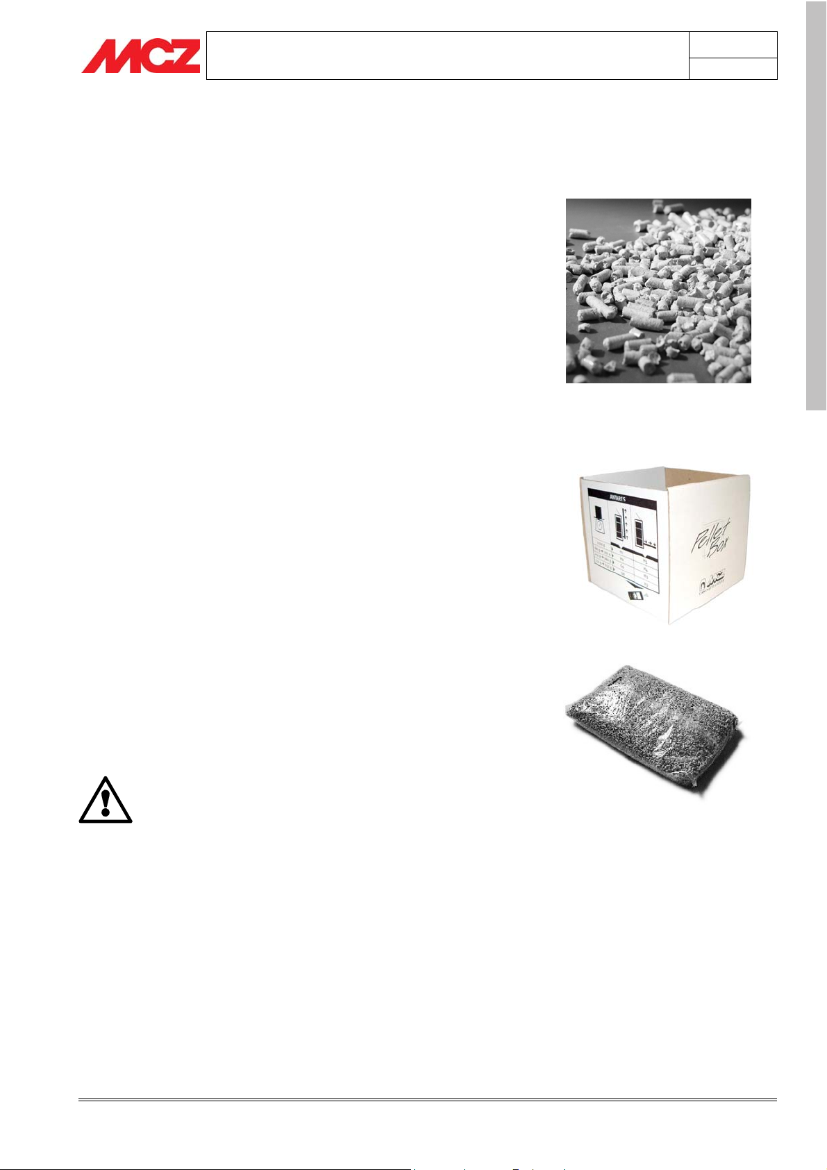
2.1. PELLETS
Wood pellets are manufactured by hot-extruding compressed sawdust
which is produced during the working of natural dried unpainted wood.
The compactness of the material comes from the lignin which is
contained in the wood itself, and allows the production of pellets
without the use of glues or binders.
The market offers different types of pellet with characteristics which
vary depending on what mixture of woods is used. The diameter goes
from 6 mm to 8 mm and the standard length is between 5 mm and 30
mm. A good quality pellet has a density between 550 kg/m
3
with a water content that is between 5% and 8% by weight.
kg/m
In order to guarantee the stated hourly consumption rates and
to optimise combustion, for pellet stoves MCZ has prepared a
patented method which makes it possible to identify and
classify any kind of pellet with a diameter of 6 mm and 8 mm
based on its specific weight and piece size.
By using the special PelletBox® and following the procedure set out in
the paragraph on lighting the stove, the user can determine the correct
settings for configuring the stove.
Along with being an ecological fuel which makes the best use of wood
residues thus producing cleaner combustion than that produced with
fossil fuels, pellets also have technical advantages. Whereas good wood
has a calorific power of 4.4 Kw/kg (with 15% humidity, so after about
18 months of seasoning), that of pellets is 5.3 Kw/kg.
To guarantee good combustion, the pellets must be stored in a clean,
dry place. The pellets are usually supplied in 15 kg. sacks, therefore
storage is very handy.
Good quality pellets ensure good combustion, thus lowering the
emission of harmful agents into the atmosphere.
The poorer the quality of the fuel, the more
frequently will intervention be necessary for cleaning
the internal parts, such as the grate and the
combustion chamber.
The pellets must be produced from pure wood which has not been
treated chemically.
The standards DIN 51731 and ONORM M 7135 certify a high-quality
pellet with the following characteristics:
Calorific power: 5.3 kW/kg
Density: 700 kg/m
Moisture content: 8% max by weight
Ash percentage: 1% max by weight
Diameter: 6-6.5mm
Length: 30 mm max
3
3
and 700
Pellet fuel
PelletBox®
15 Kg fuel sack
page
9
ENGLISH
Theoretical notes for installation Technical service – Rights reserved MCZ S.p.A. – Reproduction prohibited
PELLET STOVES Chapter 2
INSTALLATION AND USE MANUAL
Content: 100% untreated wood, with no added bonding
substances (bark percentage 5% max)
Packaging: in bags made from ecologically compatible or
biodegradable material
MCZ emphatically recommends using certified fuel
in its stoves.
The use of fuel of inferior quality or not conforming
to the specification given above compromises the
running of your stove and can therefore lead to the
termination of the guarantee and of the
manufacturer's responsibility for the product.
MCZ pellet stoves operate exclusively with pellets
with a diameter of 6 mm (only for Italy) and 6-8mm
(European countries) with a length between 5mm
and 30mm.
2.2. PRINCIPLES OF OPERATION
page
10
ENGLISH
The pellets are picked up from the hopper on board the stove and
transported by a feed screw. They are then introduced into the
combustion chamber and fall directly into the stainless steel grate.
The quantity of pellets introduced into the grate and the corresponding
air of combustion are predetermined, programmed and controlled by an
electronic board.
In the lighting phase, the electronic board activates the smoke
extraction fan and the ceramic sparkplug, which heats up and causes
the fuel to ignite at a temperature of about 200°C. After about 20
minutes, the lighting phase is complete, and the control unit puts the
stove into operating mode.
In this phase, on the basis of the instructions which we provide via the
infrared remote (5 power levels), the electronic board regulates the
exact relationship between quantity of fuel, combustion air and
convection air, and provides continuous monitoring of all the
components connected to it, indicating if necessary the presence of any
operating problems and stopping the process.
- SEE SECTION DRAWING ON NEXT PAGE -
Theoretical notes for installation Technical service – Rights reserved MCZ S.p.A. – Reproduction prohibited

PELLET STOVES Chapter 2
INSTALLATION AND USE MANUAL
2.2.1. Section plane of an MCZ pellet stove
Pellet loading door
Pellet compartment sensor
Ceramic cladding
Control panel
page
11
Convection hot air outlet
Ventilated hot air outlet
Degflector grill
Glass cleaning air
Firebox in Alutec®
Door with glass (750° C)
Stainless steel grate
Secondary combustion air
Primary combustion air
Central ash drawer
Rear closing panel
Pellet hopper
Chamber (heat exchanger)
Pellet feeding
Pellet feed screw
Pellet duct
Electronic control board
Combustion air intake Ø 50
Smoke sensor
ENGLISH
Side ash drawer
Smoke discharge Ø 80
Hot air fan
Smoke aspirator
Door handle
-
Theoretical notes for installation Technical service – Rights reserved MCZ S.p.A. – Reproduction prohibited
INSTALLATION AND USE MANUAL
2.3. WORKING ENVIRONMENT
PELLET STOVES Chapter 2
page
12
For proper functioning and a good temperature distribution, the stove
should be positioned in a location where it is able to take in the air
necessary for combustion of the pellets (about 40 m
3
/h must be
available) ,as laid down in the standard governing the installation (UNI
- CIG 7129, 7131 and in accordance with national standards in effect).
3
The volume of the room must not be less than 30 m
.
The air must come in through permanent openings made in walls (in
proximity to the stove) which give onto the outside, with a minimum
cross-section area of 100 cm
2
.
These openings must be made in such a way that it is not possible for
them to be obstructed in any way.
Alternatively, the air may be drawn from rooms next door to the room
which needs ventilation, provided that these rooms have an air intake
from outdoors and are not used as bedrooms or bathrooms and
provided there is no fire risk such as there is for example in garages,
woodsheds, and storerooms.
It is not permissible to install the stove in bedrooms,
bathrooms or showers, and in a room where another
heating appliance is installed (fireplace, stove etc.)
which does not have its own independent air intake.
Locating the stove in a room with an explosive
atmosphere is prohibited.
The floor of the room where the stove is to be
installed must be strong enough to take its weight.
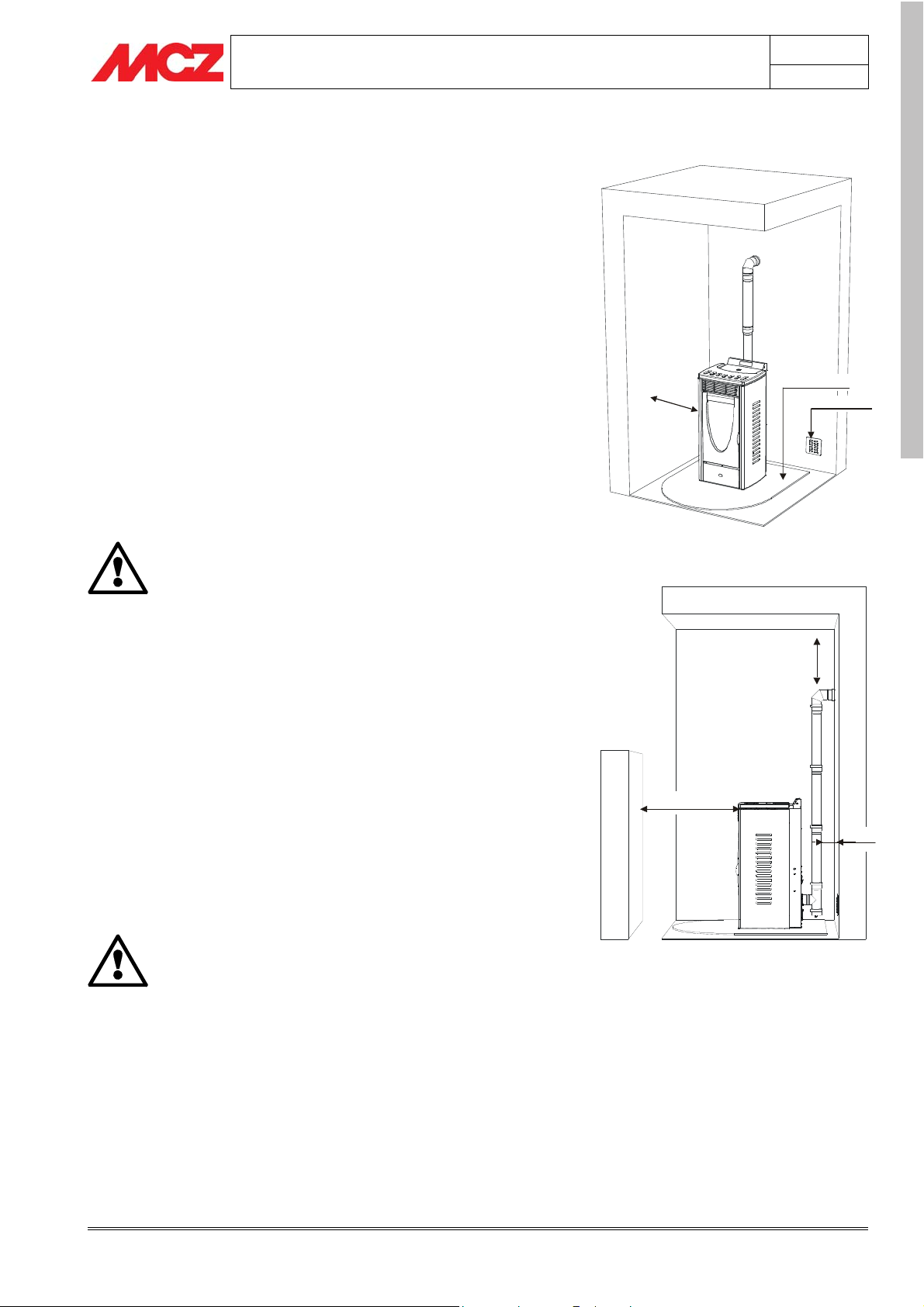
If the walls are not flammable, position the stove with a clearance to
the rear of at least 10 cm
In the case of walls made of flammable material, maintain a minimum
clearance to the rear of 20 cm, a clearance to the sides of 50 cm, and a
clearance to the front of 150 cm If the room contains objects which
are believed to be particularly delicate, such as hangings, sofas and
other furniture, their distance from the stove should be considerably
increased.
If there is wood flooring, place a floor protection
and adhere to national standards currently in effect.
5
0
c
m
Example of installation with Saturn stove
150 cm
Example of installation with Saturn stove
Floor protection
Min. 100 cm
20 cm
ENGLISH
2
20 cm
Theoretical notes for installation Technical service – Rights reserved MCZ S.p.A. – Reproduction prohibited
PELLET STOVES Chapter 2
INSTALLATION AND USE MANUAL
2.4. PRECAUTIONS
IMPORTANT !
Installation and assembly of the stove must be
carried out by a qualified engineer.
The stove must be installed in a suitable position to allow the normal
operations of opening and ordinary maintenance.
The site must be:
• capable of providing the environmental conditions for operation
• provided with 230V 50 Hz (EN73-23) electricity supply
• capable of taking an adequate system for smoke discharge
• provided with external ventilation
• provided with an earth connection complaint with CE standards
The stove must be connected to a flue pipe or an internal or
external vertical conduit conforming to the current standards.
The stove must be positioned in such a way that the electrical
plug is accessible.
IMPORTANT !
The stove must be connected to a flue pipe or a
vertical conduit which can discharge the fumes at the
highest point of the building.
The fumes are however derived from the combustion
of wood products, and if they come into contact with
or close to walls, they can make dirty marks.
Also take care because the fumes are very hot but
almost invisible, and can cause burns on contact.
The holes for the passage of the smoke pipe and for
the intake of air from outside should be made before
positioning the stove unit.
page
13
ENGLISH
2.5. CONNECTION TO THE EXTERNAL AIR INTAKE
It is essential that at least as much air must be able to flow into the
room where the stove is installed as is required for proper combustion
in the appliance and for the ventilation of the room.
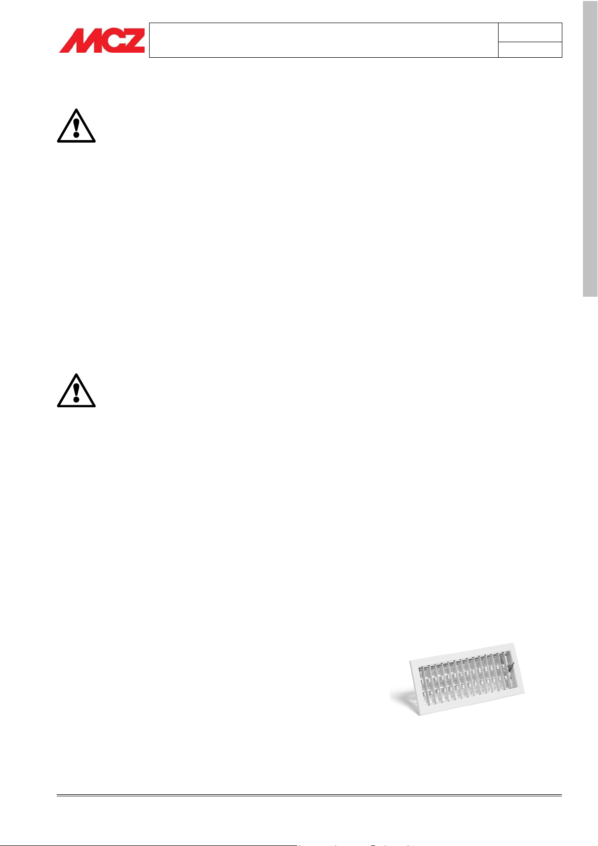
To do this, make a hole in the external wall near the stove with a
clearance section of at least 100 cm². (12 cm diameter hole or square
10x10cm), protected by a grille on the outside.
The air intake must:
• communicate directly with the room where the stove is installed
• be protected by a grille, metal mesh or suitable guard, as long as
this does not reduce the area below the minimum.
• be positioned in such a way as to be impossible to obstruct
Theoretical notes for installation Technical service – Rights reserved MCZ S.p.A. – Reproduction prohibited
PELLET STOVES Chapter 2
t
Minimum 1,5
2m
INSTALLATION AND USE MANUAL
It is not compulsory to connect the air intake directly
with the stove (so that it draws air directly from
outside), but it is essential at all events to ensure an
airflow of 50 cubic metres per hour by the use of a
hole of the dimensions given.
See standard UNI 10683 REV.
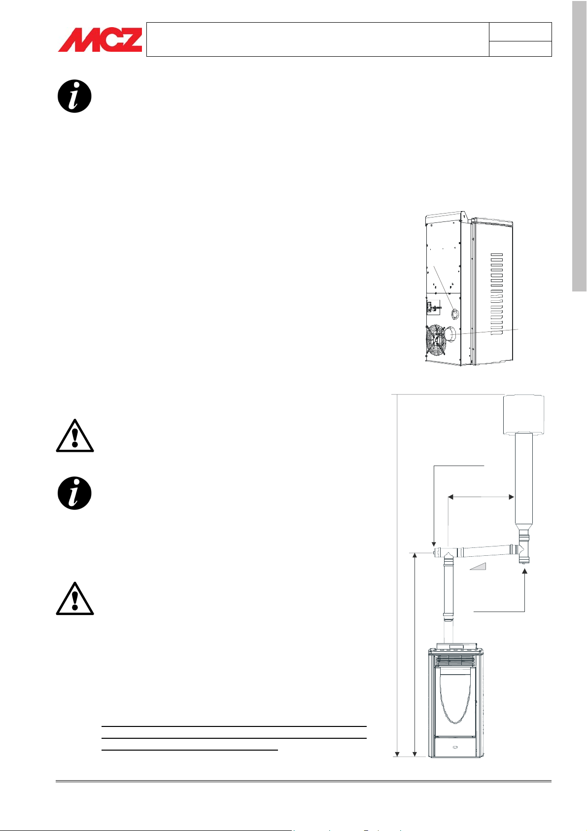
2.6. CONNECTION OF THE SMOKE DISCHARGE PIPE
page
14
When making the hole for the passage of the smoke discharge pipe, it
is necessary to take into account the possible presence of flammable
materials. If the hole will be going through a wall made of wood or any
other material which is sensitive to heat, the INSTALLER MUST first
of all use the special wall union (diam.13cm minimum) and properly
insulate the pipe of the stove that passes through it, using adequate
insulation materials (thickness1.3—5 cm with minimum thermal
conductivity of 0.07 W/m°K).
The same is true if the stove pipe must run through vertical or
horizontal stretches passing in proximity (min.20cm) to the heatsensitive wall
As an alternative we recommend the use of insulated pipe, which can
also be used on the outside to avoid condensation.
The combustion chamber works in low pressure. The smoke duct for
the discharge of fumes will also be under low pressure when connected
to an efficient flue pipe as directed.
Pipes and unions with suitable gaskets must always
be used, to guarantee a hermetic seal.
All sections of the smoke duct must be accessible for
inspection and removable to enable periodic internal
cleaning. Tee connectors with inspection caps should be
used.
Position the stove in consideration of all the instructions and
considerations above.
IMPORTANT !
All 90 degree changes of direction in the flue pipe
must be fitted with suitable tee connectors to allow
the possibility of inspection (see the pellet stove
accessory list).
It is absolutely unacceptable to fit a grille on the end
of the discharge pipe, because it could lead to poor
running of the stove.
FOR FLUE PIPE CONNECTION DO NOT USE MORE
THAN 2-3 M. OF HORIZONTAL PIPES AND DO NOT
USE MORE THAN THREE 90° BENDS
Combustion
air
Height greater than 4 m
–
Example of installation with Saturn stove
View of Saturn stove
Inspection
2-3 m MAX.
ENGLISH
Smoke
outle
3-5 %
Inspection
Theoretical notes for installation Technical service – Rights reserved MCZ S.p.A. – Reproduction prohibited
PELLET STOVES Chapter 2
A
INSTALLATION AND USE MANUAL
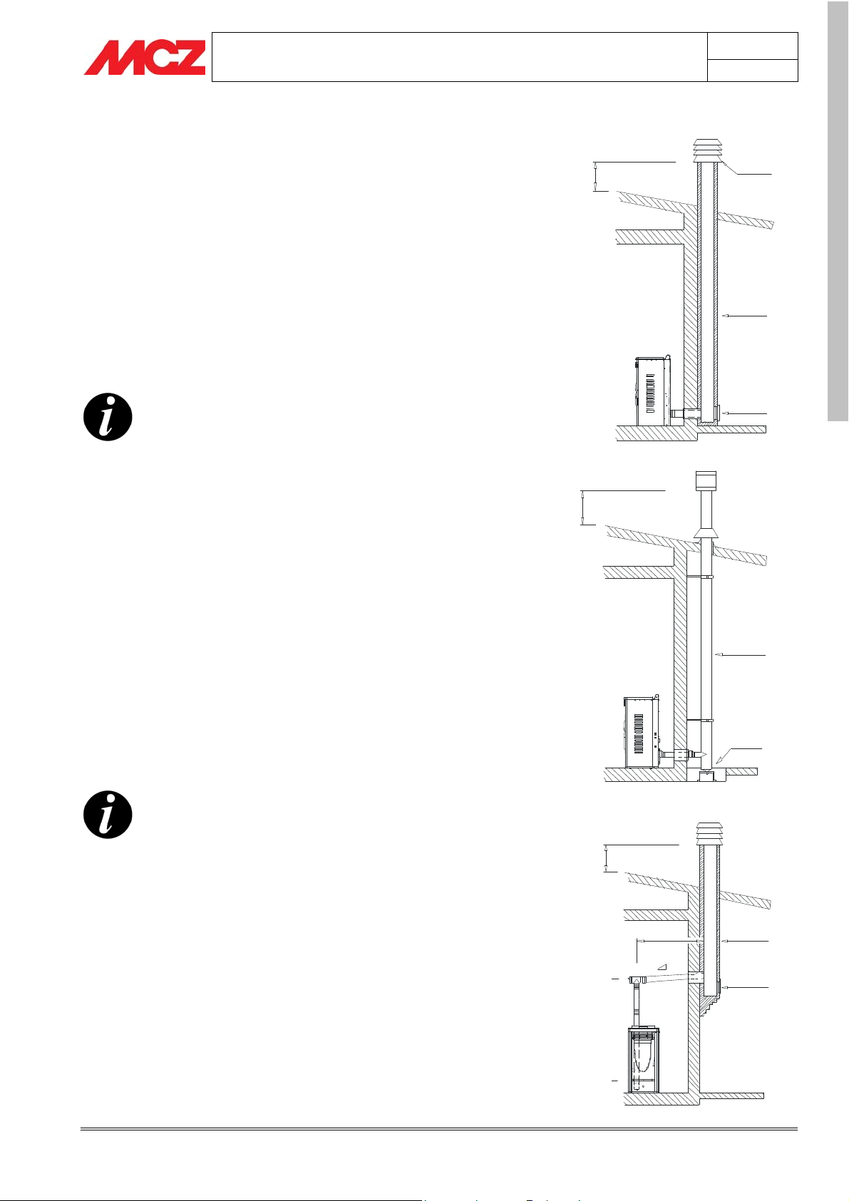
2.7. CONNECTION TO THE FLUE PIPE
The flue pipe must have internal dimensions not greater than 20x20
cm or a diameter of 20 cm; in the case of larger dimensions or poor
operation of the flue pipe (e.g. cracks, poor insulation, etc.) it is
advisable to insert a stainless steel pipe of a suitable diameter all the
way up to the top. Fig.5
Check with suitable instruments that there is a minimum draught of 10
Pa.
At the bottom of the flue pipe, provide an inspection cap to allow
periodic checking and cleaning, which must be done annually.
Make a gas-tight connection to the flue pipe, using pipes and
connectors as recommended by us.
It is compulsory to check that an anti-wind chimney has been installed,
in accordance with current standards.
This type of connection ensures the evacuation of the
fumes even in the event of a temporary power cut.
Fig. 5
0,5 m
page
15
nti-wind
chimney
Flue pipe
ENGLISH
Inspection
2.8. CONNECTION TO AN EXTERNAL FLUE WITH
INSULATED OR DOUBLE-SKINNED PIPE
The outside flue must have minimum internal dimensions of 10X10 or a
diameter of 10 cm and maximums 20x20 cm or a diameter of 20 cm;
Check with suitable instruments that there is a minimum draught of 10
Pa. Fig.6
The only type of pipe which is permissible is insulated (double-walled)
stainless steel, smooth on the inside, fixed to the wall. Flexible stainless
steel pipe must not be used.
At the bottom of the flue pipe, provide an inspection cap to allow
periodic checking and cleaning, which must be done annually.
Make a gas-tight connection to the flue pipe, using pipes and
connectors as recommended by us.
It is compulsory to check that an anti-wind chimney has been installed,
in accordance with current standards.
This type of connection ensures the evacuation of the
fumes even in the event of a temporary power cut.
2.9. CONNECTION TO FLUE PIPE OR SMOKE DUCT
0,5 m
Insulted
external
Fig. 6
duct
Inspection
0,5 m
For proper functioning, the connecting pipe between the stove and the
2 - 3 m MAX.
Flue pipe
chimney or flue duct must have a slope of not less than 3%. The length
of the horizontal stretch must not exceed 2/3 metres, and the vertical
distance between one tee connector and another (change of direction)
must not be less than 1.5m.
Check with suitable instruments that there is a minimum draught of 10
Pa. Fig.7
At the bottom of the flue pipe, provide an inspection cap to allow
periodic checking and cleaning, which must be done annually.
.
t
m
2
-
5
,
1
o
m
i
n
i
M
3-5 %
Inspection
Fig. 7
Minimum 1,5 – 2 m
Make a gas-tight connection to the flue pipe, using pipes and
connectors as recommended by us.
Theoretical notes for installation Technical service – Rights reserved MCZ S.p.A. – Reproduction prohibited
PELLET STOVES Chapter 2
y
INSTALLATION AND USE MANUAL
It is compulsory to check that an anti-wind chimney has been installed,
in accordance with current standards.
This type of connection ensures the evacuation of the
fumes even in the event of a temporary power cut.
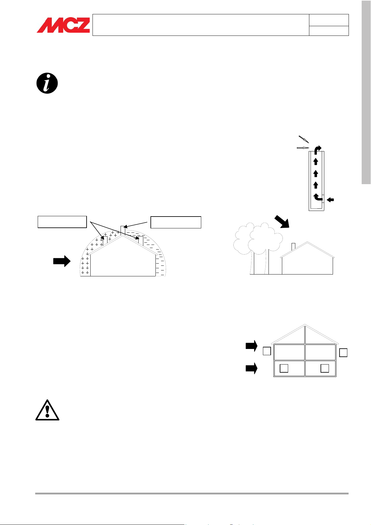
2.10. OPERATING ABNORMALITIES DUE TO FLUE
DRAUGHT PROBLEMS
45° down draft at 8m/sec. High
pressare of 17 Pa
page
16
Of all the meteorological and geographical factors which affect the
operation of a flue pipe (rain, fog, snow, altitude a.s.l., exposure to
sun, exposure to cardinal points, etc.) the wind is undoubtedly the most
important one. In fact, apart form the thermal difference caused by
the temperature difference inside and outside the chimney, there is
another kind of pressure difference: the dynamic pressure caused by
the wind. Updrafts always increase the depression and hence draft.
Horizontal wind increases draught if the chimney has been properly
installed. A downdraft always decreases the depression, at times
inverting it.
Least favorable position
Most favorable position
WIND
Pressure area
Depression area
Besides the direction and force of the wind, the position of the flue and
the cowl with respect to the roof of the building and the surrounding
landscape is important.
The wind also indirectly affects the operation of the fireplace, creating
high and low pressure areas not only outside but also inside dwellings.
In rooms directly exposed to the wind (2) a high pressure area may be
created which may favour the draught of stoves and fireplaces, but
which may be contrasted by high external pressure if the chimney is
exposed to the wind (1). On the contrary, in rooms opposite to the
direction of the wind (3) there may be a dynamic low pressure area
which competes with the natural thermal depression in the fireplace,
which may however at times be compensated by placing the smoke
duct on the side opposite from the wind (4)
IMPORTANT !
The operation of the pellet stove is noticeabl
sensitive to the conformation and position of the flue
which is adopted.
Hazardous conditions can only be overcome by
suitable setting-up of the stove carried out by
qualified MCZ personnel.
Horizontal wind 8m/sec.
Depression of 30 Pa
Down draft
WIND
1
2 3
1-2 = High pressure area
3-4 = Low pressure area
ENGLISH
4
Theoretical notes for installation Technical service – Rights reserved MCZ S.p.A. – Reproduction prohibited
PELLET STOVE Chapter 3
INSTALLATION AND USE MANUAL
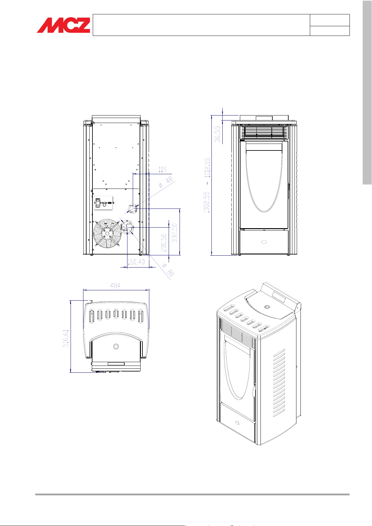
3. INSTALLATION AND ASSEMBLY
3.1. DRAWINGS AND TECHNICAL CHARACTERISTICS
3.1.1. SATURN
page
17
ENGLISH
Installation and assembly Technical service – Rights reserved MCZ S.p.A. – Reproduction prohibited
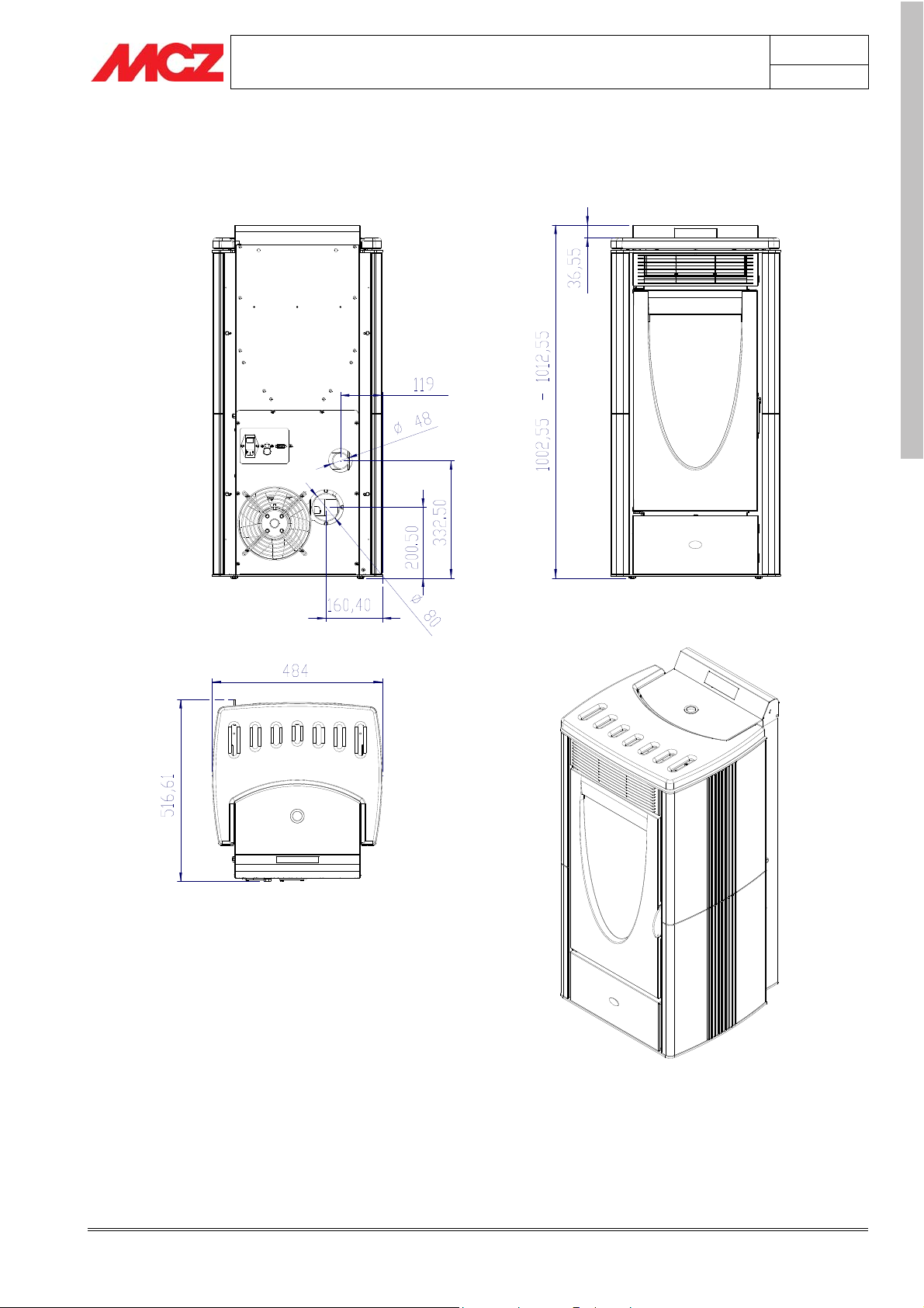
3.1.2. OMEGA
PELLET STOVE Chapter 3
INSTALLATION AND USE MANUAL
page
18
ENGLISH
Installation and assembly Technical service – Rights reserved MCZ S.p.A. – Reproduction prohibited

3.1.3. PLANET
PELLET STOVE Chapter 3
INSTALLATION AND USE MANUAL
page
19
ENGLISH
Installation and assembly Technical service – Rights reserved MCZ S.p.A. – Reproduction prohibited

3.1.4. MERCURY
PELLET STOVE Chapter 3
INSTALLATION AND USE MANUAL
page
20
ENGLISH
Installation and assembly Technical service – Rights reserved MCZ S.p.A. – Reproduction prohibited

PELLET STOVE Chapter 3
INSTALLATION AND USE MANUAL
3.1.5. TECHNICAL CHARACTERISTICS
Technical characteristics Saturn – Omega - Planet
Overall thermal power Max 7 kW / 6020 kcal
Overall thermal power Min: 1.8 ÷ 2.2 KW / 1548 ÷ 1900 Kcal
Efficiency > 80 %
Smoke temperature 120 / 210 °C
page
21
CO at 13% O
min – max 0.02 — 0.10%
²
Minimum draught 0.1 mbar / 10 Pa
Hopper capacity 25 litres
Fuel pellet type ** Pellet diameter 6-8 mm Piece size 5/30 mm
Pellet consumption per hour Min. 0.6 kg/h Max. 1.7 KG/h *
Runtime between feeds At min. 27 h * At max. 10 h *
Combustion air inlet External diameter 50 mm.
Smoke outlet External diameter 80 mm.
Net weight 120 kg.
Weight with packaging 140 kg.
Max nominal electrical power 270 W
Supply voltage 230 V -50 Hz.
Technical characteristics Mercury
Overall thermal power Max. 6 KW / 5160 Kcal
Overall thermal power Min. 2.5 KW / 2150 Kcal
Efficiency > 80 %
ENGLISH
Smoke temperature 120 / 190°C
CO at 13%O
min – max 0.01— 0.10%
²
Minimum draught 0,1 mbar—10 Pa
Hopper capacity 25 litri
Fuel pellet type ** Pellet diameter 6-8 mm Piece size 5/30 mm
Pellet consumption per hour Min 0,6 KG/h * Max. 1,4 KG/h *
Operating time between re-fuelling At min 27 h * At max. 12 h *
Combustion air inlet External diameter 50 mm.
Smoke outlet External diameter 80 mm.
Net weight 100 Kg.
Weight with packaging 120 Kg.
Max. nominal electrical power. 270 W
Supply voltage 230 V - 50 Hz.
* Data that may vary depending on the type of pellets used.
** For ITALY use only pellets with a diameter of 6mm
Installation and assembly Technical service – Rights reserved MCZ S.p.A. – Reproduction prohibited

PELLET STOVE Chapter 3
INSTALLATION AND USE MANUAL
3.2. PREPARATION AND PACKAGING
Saturn, Omega and Planet stoves are delivered in two packages:
The first contains the body (Fig. 1)
The second contains the ceramic cladding (Fig. 2)
Open the packaging, take off the bands, remove the stove unit from
the pallet and position it in the chosen location, taking care that its
position complies with the above instructions.
The main stove unit must always be moved in an upright position and a
trolley must always be used. Take particular care to see that the door
and its glass are protected from mechanical impact which could
damage them.
Moving the product must always be done with care.
If possible unpack the stove near the place where it will be installed.
The materials which make up the packaging are not toxic or harmful,
so no special procedures for disposal by required.
Their storage, disposal or possible recycling are therefore the
responsibility of the final user, in compliance with current legislation on
the subject.
Do not store the stove unit or its cladding without their packaging.
If the stove needs to be connected to a discharge pipe which goes
through the rear wall (to connect up with the flue), take the greatest
care to make sure that the joint is not stressed.
Adjust the 4 feet (J) the smoke discharge (S) and the pipe (H) are
coaxial.
If the smoke discharge of the pipe is forced or
improperly used to lift if or move, its operation will
be irreparably compromised.
page
22
ENGLISH
H
S
Installation and assembly Technical service – Rights reserved MCZ S.p.A. – Reproduction prohibited
Seen
from
below
J
Foot J
1. Rotate the foot
clockwise to lower the
stove
2. Rotate the foot
counterclockwise to
raise the stove

PELLET STOVE Chapter 3
p
INSTALLATION AND USE MANUAL
page
23
3.3. INSTALLATION OF THE CERAMIC CLADDING
FOR OMEGA-PLANET
A LOOK AT THE STOVE
In the front part there are the hooks (A) which can be adjusted in
depth and width (there are two for each tile). They should already be
attached in the coorect position.
On the back are the hooks (B) which are tentatively attached to the
frame of the stove. Loosen the screw (Z) which holds them (without
removing it completely) so that they can be moved horizontally.
TILE INSTALLATION MUST ALWAYS START FROM
THE BOTTOM.
Take a tile from the package (with its pins already inserted), mov eto
the side of the stove, and insert the tile from the front so that the
hooks (A) touch the front pin.
Rest the tile against the frame of the stove, take the rear hook (B) and,
using the screw as a grip, make the hooked ends grasp the rear pin of
the tile.
Check that the position is correct and tighten the screw all the way
down.
Repeat the procedure for the other tiles.
Install the top last, resting it on the four rubber stoppers (K). Use finger
pressure to check that the top is in a stable position. If necessary, use
the rubber stopper and the washer below it for levelling.
3.4. ELECTRICAL CONNECTION
Connect the supply cable first at the rear of the stove and then to an
electrical outlet on the wall.
The main switch located on the rear of the stove should be switched on
only when you want to light the stove.
If you do not intend to use the stove, it is advisable
to keep it switched off.
K
Hook B
Z
Hook A
Hook B
Z
ENGLISH
Rear
ceramic
pin
Hook A
Font ceramic
in
Installation and assembly Technical service – Rights reserved MCZ S.p.A. – Reproduction prohibited

PELLET STOVE Chapter 4
INSTALLATION AND USE MANUAL
4. OPERATION
4.1. WARNINGS PRIOR TO FIRST LIGHTING
Avoid touching the stove during initial lighting, since
the paint hardens during this phase. If you touch the
paint, the steel surface underneath may be
uncovered.
If necessary, touch up the paint with the spray paint of the appropriate
colour. (see "Accessories for pellet stoves")
It is good practice to provide plenty of ventilation of
the room during the initial lighting, as the stove will
give off a small amount of fumes and smell of paint.
Do not stay near the stove and as previously stated ventilate the room.
The smoke and the smell of paint will go away after the first hour of
operation. They are not harmful to your health.
The stove will be subject to expansion and contraction during the
stages of lighting and cooling down, and may therefore make slight
creaking noises.
This is absolutely normal, the structure being made of sheet steel, and
must not be considered a fault.
It is very important not to heat the stove up all at once, but to bring it
up to temperature gradually.
If in 'Manual' mode, use the lower heating levels (1st, 2nd, 3rd). On
subsequent lightings, you will be able to enjoy the full heating power
available (including 4th and 5th levels), but remember not to keep the
stove running on full power for more than 60-90 minutes.
In this way you will avoid damage to the ceramic panels, the welds and
the steel structure.
The first time the stove is lit, leave it in "Manual" mode and
use only moderate power settings, such as “on1”-”on2”-”on3”.
page
24
ENGLISH
Do not demand full heating
performance straight away!
Try to get familiar with the commands given form the control panel or
remote control.
Try to memorize the messages that the stove sends you by means of
the display panel.
Operation Technical Service – Rights reserved MCZ S.p.A. – Reproduction prohibited

PELLET STOVE Chapter 4
INSTALLATION AND USE MANUAL
4.2. CHECK PRIOR TO FIRST LIGHTING
Check that all the safety conditions described above have been met.
Make sure you have read and completely understood the contents of
this instruction booklet.
Remove everything from the stove firebox and door which might burn
(instructions and various adhesive labels).
Check that the grate A is properly positioned and rests firmly on the
base.
After long periods of disuse, remove from the hopper (using
a vacuum cleaner with an extension) any remains of
pellets which have lain there for some time, since they may
have absorbed moisture, which changes their original
characteristics and makes them unsuitable for burning.
Check that the electrical connection is correct (230 V 50 Hz), and turn
on the main switch located on the rear panel of the stove.
Check that on the control panel the display is lit up with the alternating
message
OFF / CURRENT TIME
.
A
page
25
ENGLISH
4.3. LOADING PELLETS
fuel is loaded from the upper part of the stove by opening the door.
Pour the pellets into the hopper. When empty it will hold about a 15 kg
sack.
It is easier to perform this task if it is done in two steps:
• Pour half the contents into the hopper and wait for the fuel to
settle to the bottom.
• Then pour in the second half.
Never remove the protective grille from inside the
hopper. When loading pellets, avoid the bag coming
into contact with hot surfaces.
4.4. CONTROL PANEL and REMOTE CONTROL
6
9
2
3
1
Operation Technical Service – Rights reserved MCZ S.p.A. – Reproduction prohibited
8
5
4
7

PELLET STOVE Chapter 4
INSTALLATION AND USE MANUAL
BUTTONS
1. Decrease set temperature / navigation - menu modifications
2. Increase set temperature / navigation - menu modifications
3. Set stove power
4. Set fan power
5. Stove lighting / shutdown
6. Menu / selection
7. Infrared receiver
8. Indicators (see specification)
DISPLAY
9. Display
INDICATORS
Timer active/inactive
Sparkplug in operation
Cycle where the screw delivers pellets
Hot air fan in operation/stopped
Operation in manual mode
General alarm (see specification)
4.4.1. REMOTE CONTROL and BATTERY REPLACEMENT
BUTTONS
1. Scroll down through menu / decrease set
temperature
2. Increase set temperature / programming
functions
3. Increase stove power
4. Increase fan power
Button 2+3 Lighting / Shutdown
BATTERY REPLACEMENT
The battery operates with a 12V 8LR932 alkaline battery (like those
used in gate-opening remote controls) and it is advisable to replace it
annually.
Procedure for replacement:
Put the tip of a flathead screwdriver into slot (X) of the remote control.
Turn the screwdriver clockwise so as to pry out the lid (Y).
Pull the lid (Y) completely out and replace the battery, placing it so
that its (+) is aligned with the polarity (+) marked on the body of the
remote control.
Put back the lid (Y)
Dispose of used batteries in accordance with current regulations.
page
2 3
Y
X
1 4
Polarity +
26
ENGLISH
4.5. SETTINGS TO BE MADE PRIOR TO FIRST
SWITCH
LIGHTING
Set the main switch on the rear of the stove to position (I).
The display (8) on the control panel will show the alternating message
OFF / CURRENT TIME.
If the time shown is not correct, it can be reset by the procedure
described below.
Keep in mind that the exact time is needed only when you perform
weekly programming with the TIMER (see relative chapter). On the
other hand, if the time is not up-to-date, this does not in any
compromise the operation of the stove.
4.5.1. Setting current time
Press the MENÙ key twice. The display will show the message SET
DAY and it is possible to set the day of the week using the buttons
Operation Technical Service – Rights reserved MCZ S.p.A. – Reproduction prohibited
or
LUN
SET
DAY
12:
HOUR

PELLET STOVE Chapter 4
INSTALLATION AND USE MANUAL
. If you press the
and it is possible to set the current time, again using the buttons
MENÙ key again, the message HOUR will appear
or
to increase or decrease the displayed value. To confirm the hour
selection, press the button
procedure to set the minutes on the next screen display. After confirming
the minutes with the MENÙ
complete and the display automatically exits setting and goes back to the
initial page.
You can exit time setting also by pressing the button
interrupt the procedure for more than 60 seconds, the display goes back
to the initial page.
EXITING THE MENÙ: to exit any menu screen page,
press key 5 or leave the keyboard inactive for 60
seconds
‘
MENÙ . There will then be the same
button, setting of the current time is
or if you
page
27
ENGLISH
4.5.2. Choice of display language
The LCD can communicate with the user in the following languages:
Italian, English, German, French and Spanish.
The default language is Italian. If you want to change languages,
you can easily do so as follows:
Press the MENU button , select MENU 3 using buttons or and
press the MENU button again to access language selection mode.
Modify the desired language using buttons or . To confirm the
choice you have made and exit the menu, press the button
. The
display will now operate in the desired language.
4.6. SELECTION OF RECIPE
This is an exclusive MCZ evaluation criteria which allows the
user to identify the type of pellet he has at his disposal and
therefore to set the stove up in the most appropriate manner.
This helps to avoid excessive fuel use, ensures the intended
heating potential is achieved and protects the integrity of the
product.
THE CHOICE OF RECIPE IS TO BE MADE AFTER FIRST
INSTALLATION AND EACH TIME YOU CHANGE THE
TYPE OF PELLET.
MENU 3
SET
LINGUA
LINGUA
ITALIANO
SPRACHE
DEUTSCH
(E.g. when you change supplier or when you visually detect differences
in colour or piece size)
4.6.1. HOW TO IDENTIFY THE RECIPE:
• Identification of the type of installation or connection to the flue
pipe
• Identification of type of fuel
• Identification of installation (horizontal = o,
vertical = v) see
First, identify the type of connection to the flue pipe, considering the
following:
Operation Technical Service – Rights reserved MCZ S.p.A. – Reproduction prohibited
PelletBox®

PELLET STOVE Chapter 4
INSTALLATION AND USE MANUAL
ATTENTION !
Installation is to be made exclusively to a flue pipe,
and therefore the following evaluation criteria for
identifying the installation are to be considered valid
in compliance with current standards and are the
following:
If horizontal stretches have been realized that total more
than 1.5 and there is at least one 90° bend, the type of
setting to be considered for the choice of the recipe is
unquestionably HORIZONTAL.
If it is necessary to make 3 or more curves of 45° or 90° for
connection to the flue pipe, the setting to be considered in
choosing the recipe is certainly HORIZONTAL (0).
If instead the connection to the flue pipe includes almost
all vertical stretches, or if the stove is connected directly to
the flue pipe, the setting to be considered is VERTICAL (V).
If the smoke expulsion stretch is at least 1 m long and is
horizontal and without curves, it is in any case possible to
choose a VERTICAL (V) type of setting.
The Saturn and Omega-Planet type stoves have a
default HORIZONTAL setting (for Italy, France and
Spain) which allows them to work even in the most
demanding conditions, and VERTICAL for other
European countries.
Connections which are not to the flue pipe are
generally to be considered HORIZONTAL.
For complex, segmented installations we recommend
contacting specialized personnel or authorized MCZ
service centres.
MCZ discourages other kinds of installation (with
emission that is not into a flue pipe) and declines any
responsibility for malfunctions or abnormalities.
page
28
ENGLISH
• Now let us identify the type of pellet we have available
Material requirements:
• Scales (measuring up to 4 kg) with graduations down to 10 g
• MCZ pellet measuring container supplied with stove (PelletBox®)
• A stick
• Pellets (fuel)
• Type of installation (horizontal or vertical smoke outlet) needs to
have been chosen.
Fill the measure generously with pellets without compacting it (i.e.
without banging the measure on the table or pressing the pellets down
with the hands) – Fig. 18.
Rest the batten (or ruler, blade or pencil) on the top edge of the container
and level the material by scraping off the excess. Fig. 19 and 20.
Weigh the total (measure + pellets) and note the weight.
Take the measure, empty it and turn it so as identify the graphic data
that is used for the choice of the recipe. Fig.21
Operation Technical Service – Rights reserved MCZ S.p.A. – Reproduction prohibited

PELLET STOVE Chapter 4
INSTALLATION AND USE MANUAL
4.6.2. Procedure for recipe selection
In the left-hand column, marked 'Weight', identify which row contains
the weight which was noted earlier.
Following the row across to the right, you will see two numbers which,
depending on the type of installation of the stove (with smoke outlet
predominantly vertical or horizontal) will allow you to select the
optimum recipe for the type of pellet being used.
Example:
Let us suppose that it has been decided to install the stove in the
configuration with vertical smoke outlet, and that the weight of the
measure complete with pellets is 680 grams.
First of all, identify the stove model you are dealing with (for example
SATURN), then look at the corresponding table located on a side of the
measure and you will see that on the column "Weight" that 680g is
found in the line titled “from 660 to 700”.
Staying on the same line, you will now identify the code "L2" which
corresponds to the column which has as its symbol a stove with a
vertical flue pipe. The recipe to program the stove with is L2.
V
page
29
O
ENGLISH
4.6.3. Memorization of recipe on stove.
Press MENÙ and use the button until the message “SET
RECIPE is shown on the display. Then confirm with MENÙ
now see the message “SET RECIPE”. Again using the buttons
. You will
or
you will select the number of the desired recipe as shown in the
diagram on the BoxPellet® (measuring container);
To confirm the choice press MENÙ
. The display will show the
request for confirmation, to which you must answer “YES” or “NO”.
Choose one of the two options with the buttons
with the button MENÙ
. The confirmation of the setting is shown on
or and confirm
the display by the message “LOADED PARAM”. The display will
automatically go back to the initial screen.
If you interrupt the procedure for more than 60 seconds, the display
will automatically go back to the initial screen. You can also interrupt
the operation at any time manually, by holding down
for a few
seconds.
DEFAULT SETTING:
SATURN – OMEGA – PLANET = L2
MERCURY = M2
4.7. FIRST LIGHTING
MENU 4
SET
RECIPE
L2
SET
RECIPE
20.45
OFF
You are now ready to light your stove.
Below is a quick-start list for lighting and shutting down your stove, to
satisfy your curiosity and anticipation.
Afterwards, as you are sitting comfortably in your armchair enjoying the
warmth and the sight of your stove, there will be a more in-depth
description of all of the controls and programming sequences that will
allow you to use fully everything Omega-Planet and Saturn make
available to you (see paragraph 4.9)
4.7.1. Lighting from panel
Remote control keypad
To light the stove, press key for several seconds.
Operation Technical Service – Rights reserved MCZ S.p.A. – Reproduction prohibited

PELLET STOVE Chapter 4
INSTALLATION AND USE MANUAL
4.7.2. Lighting from remote control
To light the stove, press buttons and at the same time for a few
seconds.
The stove will begin the START-UP phase, which lasts about 15
minutes. It will then begin normal operation. When lit for the first
time, the stove will be set in MANUAL operating mode.
Only after lighting, the control panel can be used to choose the desired
power and/or ventilation.
Button
following sequence:
whereas the 5 ventilations of hot air are adjusted with push button
in this sequeence:
In the "AUTO" position, ventilation autonomously adapts to the flame
power
Examples: Flame power P1 = Ventilation at 1
Flame power P2 = Ventilation at 2
……
Flame power P5 = Ventilation at 5
If after repeated failures to ignite, a flame still does not appear, even
though there is a proper flow of pellets into the burner, it indicates that
there could be a problem due to stove components or improper
installation.
is used to regulate the heating power of the stove in the
P3→P4→P5→P1→P2→P3 .
1st→2nd→3rd→4th→5th→AUTO→1
At the first lighting (and any time the pellets in the
hopper run out), it is possible that the fuel, having to
travel from the hopper to the burner, is not able to
arrive in the correct quantities and within the
required time for proper ignition. In this case the
burner will either be empty or will contain very few
pellets.
REMOVE ANY PELLETS FROM THE BURNER AND
REPEAT LIGHTING BY PRESSING BUTTON
FEW SECONDS.
REMOVE THE PELLETS FROM THE BURNER AND
REQUEST ASSISTANCE FROM AN AUTHORIZED MCZ
TECHNICIAN.
st .
st
speed
nd
speed
th
speed
FOR A
P - 3
SET
POWER
Variation of flame power
SET 3
FAN
Variation of fan speed
P - 3
20.45 21°C
ON
page
30
ENGLISH
4.7.3. Switching off from panel
To shut off the stove, press button for a few seconds.
4.7.4. Switching off with the remote control
Remote control keypad
To switch off the stove, press buttons and at the same time for a
few seconds.
The display (8) will show the message "OFF". The stove will now
automatically start the shutdown phase, during which it will interrupt
the flow of fuel and the flame will be extinguished. Ventilation will
Operation Technical Service – Rights reserved MCZ S.p.A. – Reproduction prohibited

PELLET STOVE Chapter 4
INSTALLATION AND USE MANUAL
however continue for 20-30 minutes so that all of the heat retained by
the stove will be released into the room.
4.8. VIEWING THE FLAME
In order to obtain good operation from the stove, you need to know
how to "read" the flame. The characteristics that the user needs to pay
attention to are the basically:
• The shape
• The colour
• The character
page
31
4.8.1. The shape
In normal combustion, the flame should be tapered and lively, as
wide as the grate that it comes out of and with the tip roughly vertical
or pushed towards the Alutec70 back of the firebox. You should have
the sensation that the flame is pulled upward so that it does not beat
Fig. 1
against the glass of the door.
On the other hand a flame which at its base is bigger than the grate
and has a feeble character, whose tip is not "guided", or which beats
against the glass
(Fig. 2)
may be a symptom of poor setting of the fuel
loading and/or smoke aspiration, or the smoke duct is obstructed or
there are high pressure areas that do not allow for regular smoke
outflow.
In this case you will ALWAYS have operating problems. Request
assistance from specialized personnel or ask MCZ technicians for
advice.
4.8.2. The colour
The colour is in some way connected to the shape of the flame. A
colour which varies between orange and yellow with a dark tip usually
goes along with an enlarged flame (as previously described) which
lacks oxygen or in any case indicates improper combustion. As the
colour changes to light yellow-white, the shape of the flame changes,
becoming thinner, showing the presence of a greater quantity of
oxygen.
ENGLISH
Figure 1
NORMAL COMBUSTION
Shape: Tapered, compact, vertical
Character: Lively
Colour: Yellow – light yellow - white
4.8.3. Character
Lively or feeble, this is closely connected to the shape of the flame.
Figure 2
ABNORMAL COMBUSTION
Shape: enlarged irregular not
compact
Character:Tenuous - feeble
Colour:Orange - yellow
Operation Technical Service – Rights reserved MCZ S.p.A. – Reproduction prohibited

PELLET STOVE Chapter 4
INSTALLATION AND USE MANUAL
4.9. OPERATING MODES
The SATURN and OMEGA-PLANET stoves basically have three operating
modes.
4.9.1. Manual and automatic
The stove can operate in one of these two different operating modes.
MANUAL mode allows only adjustment of the flame from power 1 to
power 5, ignoring any ambient temperature measurement. This mode
is indicated by the symbol on the display.
Automatic mode, on the other hand, lets you set the desired
temperature in the room of installation. The stove will control its power
autonomously in order to reach the established temperature. With this
mode you can also use an external thermostat as explained in
paragraph 4.9.3.2 of this manual.
At each lighting, the stove sets to the operating mode
that it was in the last time it shut down.
page
32
ENGLISH
4.9.2. Manual mode
In this mode you can only vary the thermal power provided by choosing
the flame power.
Using the button
the stove is at power 3, for example, the sequence will be:
Ventilation is also partitioned into 5 speeds (plus the AUTO position),
and it is possible to change it as you like using the key
is for example at power 3, the sequence will be:
In the "AUTO" position, ventilation autonomously adapts to the flame
power
Examples: Flame power P1 = Ventilation at 1
Flame power P2 = Ventilation at 2
……
Flame power P5 = Ventilation at 5
ATTENTION!
During stove operation, if there are conditions which
alter normal operating status, the main alarm
indicator light (6) will come on accompanied by a
beeping sound (see the paragraph "stove shutdown")
and the stove will react by starting the total
shutdown procedure.
If there is an electrical power outage during lighting
or operation of the stove, the stove will switch over to
cooling mode and it will start again when the
electricity supply is restored.
the 5 heating powers of the stove are adjusted. If
P3→P4→P5 →P1→P2→P3 .
. If ventilation
SET VENTOLA 3→4→5→AUTO→1→2→3 .
st
speed
nd
speed
th
speed
P – 3
SET
POWER
Variation of flame power
SET 1
FAN
Variation of fan speed
Stove in alarm and in lockout status
ALARM
NO
FIRE
Operation Technical Service – Rights reserved MCZ S.p.A. – Reproduction prohibited

PELLET STOVE Chapter 4
INSTALLATION AND USE MANUAL
4.9.2.1.
Changing from manual to automatic mode
To change from MANUAL to AUTOMATIC operating mode, just press
the button two times in sequence. The display will show the mode
change, the light will go off and you will need to set the desired
temperature.
As a default value, as soon as you change from manual to automatic
mode, the SET TEMP ROOM is 40°C.
40°C
MODE
AUTO
page
33
4.9.3. Automatic mode
Whereas MANUALE mode lets you simply choose the thermal power
provided with no variation of operation over time, AUTOMATIC mode
lets you set a certain temperature to be reached in the room. In this
operating mode the stove will automatically vary the thermal power
provided so as to keep the temperature in the room constantly at the
set value.
Example:
If the room temperature detected by the local sensor located on the
stove is 15 C° and the temperature set on the thermostat is 20 C°, the
stove will go sequentially to the 5th power and when the requested
temperature is reached (20 C°) it will go to ECO mode (the display will
show the message “ECO”) thus switching down to the minimum power.
It should be remembered that the temperature assigned to the
thermostat is approximate and it is up the user to find the right value in
the room where the stove is installed (e.g. it may be necessary to set
the thermostat at 25C° in order to have a room temperature of 20C°).
This happens because the room thermostat is placed near the warm
body of the stove and therefore it detects the heat from the stove.
In this mode, lighting and shutdown are performed by the user by
holding down button
To set the temperature to be reached you can use the:
for a few seconds.
Changeover from MANUAL to AUTOMATIC
09:52 16°C
ON
ECO
Operation at minimum in automatic operating
mode
ENGLISH
4.9.3.1.
The stove includes an internal digital thermostat. By means of a
sensor, it measures the room temperature and compares it with the
temperature set by the user.
Internal digital thermostat (equipped in the stove)
21°C
SET TEMP
ROOM
To increase the set temperature in steps of 1 degree centigrade,
press the button
.
4.9.3.2.
External thermostat (optional)
. In the same way, to decrease use the button
Adjustment of room temperature to be
reached
The EXTERNAL THERMOSTAT is not included with
stove and its installation is to be handled by the user.
The stove can also be connected to an external room thermostat, which
would replace the one on the stove. In must be placed in a median
location in the room of installation, so as to better monitor the room
temperature.
The procedure to follow for the connection of the external thermostat is
the following:
Operation Technical Service – Rights reserved MCZ S.p.A. – Reproduction prohibited

PELLET STOVE Chapter 4
MCZ
l
INSTALLATION AND USE MANUAL
• Connect the two wires of the cable from the thermostat to the
terminal of the MCZ connector (not included with the stove).
Insert the connector in the appropriate serial socket located on
the back of the stove.
• In order for the stove to recognize the external thermostat,
press and hold the button
scrolling through the temperature
values below 6°C until the message “REMOTE TEMP.”
appears. This means that the external thermostat is now active
and overrides the internal one.
Wiring from
external thermostat
page
34
seria
connector
4.9.3.3.
Changing from automatic to manual mode
To change back from MANUAL mode to AUTOMATIC mode, do the
following:
press and hold the button until the temperature is over 40°C. The
display will now show the message “MODE MANUAL” and the light
will come on.
4.9.4. Automatic mode with ECO-STOP
When this option is activated by the corresponding menu item, the
operation of the stove is modified in automatic mode. When the
temperature set by the user is reached (on either the internal or
external thermostat), instead of adjusting power, the stove goes off
and shows the message "ECO STOP”. It will light again when the room
required heating again (not before the period of time required for the
stove to cool off). This option is advisable only if the stove operates in
small, well-insulated rooms.
Example:
If the room temperature detected by the room probe located on the
stove is 15°C and the temperature set on the thermostat is 20°C, the
stove will ramp up to the 5th power and upon reaching the target
temperature of 20°C it will automatically shut off temporarily, displaying
the message “
Eco Stop
value set on the thermostat (e.g. 18°C) the stove will come back on
automatically, and it keeps running until 20°C is once again reached. If
the temperature read by the room probe goes above the value set on
the thermostat (e.g. 20-21°C) the stove stays off and the display shows
the message “
Eco Stop
It must be remembered however that the temperature keyed into the
thermostat is only indicative, and it is up to the user to find the correct
setting in the location where the stove is installed (for example, to
achieve 20°C in the room, it may be necessary to set the thermostat to
25°C). In this mode, the user can light the stove by setting the
thermostat temperature to a value which is higher than room
temperature or by pressing button
and subsequently, by pressing the same button, proceeding with
lighting.
However, i this last case, the stove will go back to MANUAL mode in
"ON 3" This means you will have to reset to AUTOMATIC mode if you
want the stove to be controlled by the thermostat.
”. When the room temperature drops below the
”
to change over to "Off" mode
Connection of external thermostat serial
connector in the special socket on the back of
the stove
MENU 5
SET
E C O - STOP
ENGLISH
Operation Technical Service – Rights reserved MCZ S.p.A. – Reproduction prohibited

PELLET STOVE Chapter 4
INSTALLATION AND USE MANUAL
HOW THE STOVE WORKS WITH THE TIMER ACTIVE:
The stove is in... The timer cuts in
The stove...
to…
ECO STOP Switch off the stove
ECO STOP Light the stove
Switches off permanently
and goes to OFF
Remains in ECO STOP
status
page
35
4.9.4.1.
ECO-STOP mode activation
This mode makes it possible to optimize stove consumption in wellinsulated rooms.
Press the MENÙ
button
until you reach the 5
button on the control panel, then the
th
screen which shows the
message “SET ECO-STOP”;
Again press MENÙ
the button
or ;
To exit press the button
and set ON at the display screen with
(or the button ).
To disable the eco-stop function follow the same procedure.
4.9.5. Programmed mode
This operating mode which is indicated at lighting by indicator light (7)
on the display makes it possible to program lighting and shutdown of
the stove automatically over the course of a week.
Saturn and Omega stoves normally have PROGRAMMED mode
de-activated. (indicator light 7 off).
The basic characteristics of PROGRAMMED mode are:
• Start day
• Clock
• Program (4 daily programs are available)
Italiano
LUN
MAR
MER
GIO
VEN
SAB
DOM
LUN
MAR
MER
JEU
VEN
SAM
DIM
(9)
LUN
MAR
MIE
JUE
VIE
SAB
DOM
~
Display
Deutsch Francais Espanol
MON
DIE
MIT
DON
FRE
SAM
SON
English
MON
TUE
WED
THR
FRI
SAT
SUN
ENGLISH
4.9.5.1.
Current date and clock
See paragraph 4.5.1. to learn how to set the current date and time.
Setting the current date and time is essential for
proper timer operation.
4.9.5.2.
Timer activation
The following is an explanation of how to ACTIVATE THE TIMER
FUNCTION:
press the MENÙ
“SET TIMER” screen, then again MENÙ
item which is “SET TIMER". Use the buttons
to ON. The signal on the icon
button followed by the button to access the
to enter the first timer
or to set the timer
will come on immediately to show
that the timer is active. To continue scrolling the various programmes
for turning the timer on/off, just press the key
To exit the timer menu at any time, press the button
.
.
Operation Technical Service – Rights reserved MCZ S.p.A. – Reproduction prohibited

PELLET STOVE Chapter 4
INSTALLATION AND USE MANUAL
SUMMARY:
To ACTIVATE the PROGRAMMED mode, press in sequence MENU >
button
the timer. To exit press
> MENÙ , then the buttons or to set ON activating
.
ATTENTION !
If the timer function is active, the icon
any operating screen
will be on in
To DE-ACTIVATE THE TIMER FUNCTION follow a procedure similar
to that for activation: press in sequence the menu button > button
> menu , then the buttons or to set "SET TIMER" to OFF thus
de-activating the timer. To exit press.
ON (OFF)
SET
TIMER
Activation of programmed mode.
page
36
ENGLISH
4.9.5.3.
Programme
The Saturn and Omega-Planet stoves can be set with up to 4 operating
programmes divided over the course of the entire day or entire week.
Each programme is characterized by three basic steps:
• The stove lighting time (must be between 00:00 and
23:40)
• The stove shutdown time (it must be later than the
lighting time, up to a time no later than23:50)
• The days on which the lighting and shutdown times are
to be ACTIVATED or DEACTIVATED
Let's analyse PROGRAMME 1 (summarized in the table below) which
is the first of four in the programming sequence.
PROGRAMMA 1
MENU’
SET
TIMER
Symbol
on display
• Press MENÙ
“SET TIMER” screen on the display.
• Now press MENÙ
1: use buttons
time (in steps of 10 minutes), then confirm with MENÙ
(see fig. alongside)
• This screen concerns the programme end. Also here, use the
buttons
confirm with MENÙ
• Now choose the day when you want the set time to take effect.
With the button
display. As you scroll through the days with the button
START
PROGRAM.1
STOP
PROGRAM.1
DAYS
PROGRAM.1
Lighting Time Shutdown Time Active or inactive days
- On/Off
followed by the button until you reach the
twice to set the start time for programme
and to increase or decrease the start
.
and to increase or decrease the end time, then
set to ‘ON’ or ‘OFF’ the day shown on the
you
07:30
START
PROGRAM.1
09:30
STOP
PROGRAM.1
Operation Technical Service – Rights reserved MCZ S.p.A. – Reproduction prohibited

PELLET STOVE Chapter 4
INSTALLATION AND USE MANUAL
will see at the side whether the programme is ‘ON’ or ‘OFF’ on
that day (see example below). To confirm press “menu”.
Example
Set the on time (for example 7:30) and the off time (for example
9:30) for programme 1, and set the stove so that it runs this
programme on Mondays, Wednesdays, and Fridays.
• Press MENÙ
followed by the button to reach the “SET
TIMER” screen on the display.
• Now press MENÙ
the buttons
the time quickly). Upon completion press MENÙ
twice and set the on time for 07:30 using
and (you can hold down the button to scroll
• This other screen concerns stove shutdown. Again, use the
buttons
and to set 09:30, then confirm with MENÙ
• Now select the day when you want the set time to take effect.
With the button
use the button
and set the day ‘TUE’ (Tuesday) to ‘OFF’ with the button
Press again the button
(Wednesday) set ‘ON’ with the same button as before
select the day. Stop at ‘MON’ (Monday) and
to set it to ‘ON’. Press the button again
.
and for the third day ‘WED’
.
Continue in this manner until ‘SUM’ (Sunday). To confirm the
entire procedure, press MENÙ
. (see fig. alongside).
Continuing with MENÙ it is possible to set other days and
other times for programmes 2, 3 and 4, which appear in
sequence after programme 1.
For the on time for each programme, it is possible to set the option
“OFF” by scrolling the time to after 23.30 or before 00.00. In this case
the current programme is disabled. If you press MENÙ
you will go
directly to the start-up of the next programme. The programme reactivates for navigation if a valid start time is set.
page
MON ON
DAYS
PROGRAM.1
SUN OFF
DAYS
PROGRAM.1
37
ENGLISH
IMPORTANT NOTE
When the stove is lit, it takes 20 minutes before sufficiently
hot air comes out of it and another 10 minutes before it is
running at full power. When setting the lighting time, take this
time lapse into account. In the same manner, shutdown of
the stove requires about thirty minutes, and during this time
the stove continues to give off accumulated heat. Keep this in
mind in order to obtain substantial fuel savings.
Operation Technical Service – Rights reserved MCZ S.p.A. – Reproduction prohibited

PELLET STOVE Chapter 4
INSTALLATION AND USE MANUAL
4.10. SAFETIES
The stove is fitted with the following safety devices:
• PRESSURE SWITCH
Monitors pressure in the smoke duct. It is designed to shut down
the pellet feed screw in the event of an obstructed flue or
significant back-pressure (from the wind).
• SMOKE TEMPERATURE SENSOR.
Monitors the temperature of the smoke, and gives permission for
start-up or shuts the stove down when the smoke temperature
falls below the preset value.
• FUEL HOPPER TEMPERATURE SENSOR.
If the temperature exceeds the preset safety level, it immediately
shuts down the running of the stove, and has to be reset manually
before the stove will restart. Take care when carrying out the
operation of resetting it, because if the stove locks out a second
time, it will be necessary to call the technical assistance centre.
• ELECTRICAL SAFETY
The stove is protected against violent surges of current by the
main fuse, which is located on the control panel at the rear of the
stove. Other fuses to protect the electronic boards (main board
and heat-exchanger board) are to be found on the boards
themselves.
• FAILURE OF THE SMOKE EXTRACTION FAN
If the fan stops, the electronic board shuts off the supply of pellets
in good time, and an alarm message is displayed.
• BREAKDOWN OF THE REDUCTION MOTOR
If the reduction motor stops, the stove continues to function until
it has cooled down to the minimum level.
• TEMPORARY POWER OUTAGE
After a brief absence of electrical current, the stove goes to
cooling mode and then comes back on automatically.
• FAILURE TO LIGHT
If no flame develops during the lighting phase, the stove goes into
alarm status.
TAMPERING WITH THE SAFETY DEVICES IS
PROHIBITED
It is only after eliminating the cause which gave rise to the
intervention of the safety system, that it is possible to relight
the stove and thus reset the automatic operation of the
sensor. To understand what sort of problem has arisen, refer
to paragraph 4.11.1 of this manual which explains what to do
based on the kind of alarm message the stove is showing.
page
38
ENGLISH
Operation Technical Service – Rights reserved MCZ S.p.A. – Reproduction prohibited

PELLET STOVE Chapter 4
g
T
INSTALLATION AND USE MANUAL
Attention!
If the stove is NOT used as described in this instruction
booklet, the manufacturer refuses to accept any responsibility
for damage to persons and property that may arise. The
manufacturer furthermore refuses to accept responsibility for
damage to persons and property arising from the failure to
observe all the rules contained in the manual and in particular:
• Failure when carrying out works of maintenance,
cleaning and repair to adopt all necessary measures and
precautions
• Tampering with the safety devices.
• Removing the safety devices.
• Failure to connect the stove to an efficient system for the
discharge of smoke.
• Failure to check in advance that the room where the
stove is to be installed is adequately ventilated.
page
39
ENGLISH
4.10.1. Alarm indications
In the event that a running problem occurs, as the stove is equipped
with a computerised monitoring system, it informs the user via the
display (8) of the nature of the fault and where it has occurred.
The following table summarises the principal alarms which may be
indicated
Messa
e on the
display (8)
ALARM
SMOKE DEPRESS.
ALARM
SMOKE FAN
ALARM
SMOKE PROBE
ALARM
PELLET TEMP.
ALARM
NO START
Smoke extraction is low because of obstruction of
the flue or back-pressure
Smoke fan jammed.
Fan speed too low
Smoke sensor short circuit Replace smoke sensor
he temperature of the pellet hopper is above the
preset threshold
Occurs on first failed attempt at lighting Check level of pellets in hopper. Check/replace
Type of problem Solution
Check and clean the WHOLE flue system
Replace the smoke fan
Heat exchanger not working.
No voltage at exchanger.
Check the parameters of the recipe used.
spark plug.
ALARM
NO
FIRE
ALARM
SMOKE TEMP
ALARM
NO FIRE
The smoke temperature has exceeded certain preset limits
Occurs when the stove goes out and when the
temperature of the smoke sensor is below the
preset threshold.
The stove will shut off automatically. Let the stove
cool off for a few minutes, then re-light it.
Derives from a failure to light. See above.
Operation Technical Service – Rights reserved MCZ S.p.A. – Reproduction prohibited

PELLET STOVE Chapter 4
INSTALLATION AND USE MANUAL
4.10.2. Other alarm signals
The following table summarizes the messages which may appear on the
display
MESSAGE ON DISPLAY
PANEL
OFF The stove is off
MANUAL The stove is in manual mode
ON The stove is on
START Lighting sequence
P-1 … P-5 Stove operating in manual mode at indicated speed (1,2,3,4 or 5)
ECO-STOP Stove in automatic mode with "shutdown with temperature"
20°C Example of room temperature
MON….SUN Days of the week
DAY day
HOUR hour
MINUTE minutes
ACCESS CODE access key
SET setting
CLEANING Automatic cleaning of the brazier in the set period of time
MCZ SPA mcz spa
MEANING
page
40
ENGLISH
4.10.3. Lockout of the stove
The following things can cause the stove to lock out:
• Overheating of the stove body
• High pressure in the outlet fumes (as read by the pressure
switch) and therefore possible obstruction of the smoke
discharge system or external back-pressure.
The lockout is indicated by the LED (6) lighting up, accompanied by an
audible "beep".
In this situation the shutdown cycle is automatically activated.
Once this process has started, any operation which is an attempt to
reset the system is useless.
The cause of the lockout is shown on the display (8).
WHAT TO DO:
When the stove is cold:
If the message "Alarm hot pel" appears, it will be necessary to
unscrew the cover of the thermostatic sensor fitted to the back of the
stove and press the red button to reset it. Refit the protective cover.
Fig.24-25
If the message "Alarm Press" appears, you need to check if ALL of
the smoke duct, including the combustion chamber, is clean and free of
obstructions. (it is advisable to have this done by a specialized MCZ
technician)
Only after the cause of the blockage has been permanently
eliminated can a fresh attempt to relight the stove be made.
Fig. 24 – Bulb probe reset button
Fig. 25 – How to reset the bulb thermostat once
the stove is cold.
Operation Technical Service – Rights reserved MCZ S.p.A. – Reproduction prohibited

PELLET STOVE Chapter 4
INSTALLATION AND USE MANUAL
4.11. SHUTTING DOWN THE STOVE
The stove can be shut down at any time and in whatever state it is in.
NEVER SHUT DOWN THE STOVE BY DISCONNECTING
THE ELECTRICAL POWER SUPPLY
Always leave it to complete the shutdown cycle,
otherwise damage could be caused to the structure,
and also problems with lighting in the future.
To shut down the stove, press button on the control panel
for a few seconds, or simultaneously press
remote control
The display (8) will show the message “OFF”. At this moment the
shutdown cycle begins, in which the pellet loading screw stops, while
the smoke extractor and the hot air exchanger remain on until the
temperature of the stove has fallen sufficiently.
The actual shutdown of the stove only occurs 20 - 30 minutes later,
and in any case not before the smoke temperature falls below 50 °C.
This occurs to allow the combustion fumes to be ducted into the flue
pipe by means of the extractor.
It also means that there is total recovery of the heat yielded by
combustion to the structure of the stove.
and on the
page
41
Remote control keypad
ENGLISH
Operation Technical Service – Rights reserved MCZ S.p.A. – Reproduction prohibited

PELLET STOVE Chapter 5
INSTALLATION AND USE MANUAL
5. MAINTENANCE AND CLEANING
ATTENTION !
All operations of cleaning all parts must be carried out
with the stove completely cold and with the electric
plug pulled out.
The stove does not need much maintenance if used with
certified quality pellets. The necessity for maintenance
increases with use and depending on the performance
requested of it.
5.1. CLEANING TO BE DEALT WITH BY USER
page
42
ENGLISH
Before EACH LIGHTING
Use the special tool to clean the grate of ash and any incrustation
which could obstruct the passage of air. Fig.26
Remember that only a clean and tidy grate can
guarantee perfect operation of your pellet stove.
A simple visual check, made once a day, will indicate
the efficiency of the grate.
To clean the grate properly, pull it all the way out of its place and
thoroughly clean the holes and the grate on the bottom. If you use
good quality pellets, it usually only takes a brush to get the grate back
into perfect working order. If there are tough incrustations, use the
steel tool provided standard with the stove.
CHECK EVERY 2/3 DAYS
Clean and empty the ash drawers, watching out for hot ash. Fig.27
Only if the ash is completely cold is it possible to use a vacuum
cleaner to remove it. In this case use a vacuum cleaner suitable for
picking up particles of a certain size, such as a drum vacuum cleaner.
Experience, and the quality of the pellets used, will determine the
frequency of cleaning.
It is however advisable not to let it exceed 2 or 3 days.
When the job is completed, re-close the ash drawers, making sure that
they are properly shut.
CLEANING THE GLASS
For cleaning the ceramic glass, the use of a dry brush is recommended,
or if it is very dirty, the special spray detergent, applying a small
quantity then cleaning with a cloth. Fig.28
ATTENTION !
Do not spray the product on the painted parts or on
the door seals (ceramic fibre cord).
Fig. 26 – CLEAN GRATE
Fig. 26 – DIRTY GRATE
Fig. 27 –Ash collection compartment cleaning
Fig. 28 – Glass cleaning
Maintenance and cleaning Technical service – Rights reserved MCZ S.p.A. – Reproduction prohibited

PELLET STOVE Chapter 5
g
INSTALLATION AND USE MANUAL
5.2. CLEANING TO BE DONE BY A SPECIALIZED
TECHNICIAN
CLEANING OF HEAT EXCHANGER
Open the upper plug (Fig. 29) and use a stiff rod to scrape the walls of
the firebox so that the ashes fall to the part below.
Still with the stove cold, open the door below the grate (Fig. 30) and
with a vacuum cleaner remove the ash and soot accumulated in the
heat exchanger.
Clean the smoke discharge system, especially in the area of the tee
connectors and of any horizontal stretches of pipe.
For information refer to a chimney sweep.
ATTENTION: For your safety, the frequency of
cleaning the smoke discharge system must be
determined on the basis of how the stove is used.
Check the seal of the ceramic fibre gaskets on the stove.
If necessary order new gaskets from your dealer as replacements.
At the end of the season it is necessary to clean the compartment
under the grate and the heat exchanger inside it.
This general cleaning should be carried out at the end of the season in
order to facilitate the general removal of all residues of combustion,
without waiting too long, because with time and humidity these
residues can become compacted.
Fig. 29 – Upper plug
page
Upper
plu
43
Upper
plug
Lower
plug
ENGLISH
4.6 Shutting the stove down (end of
season)
At the end of season, before placing the stove in storage, we
recommend completely removing pellets from the hopper with the use
of a vacuum cleaner with an extension.
In the period when the stove is out of use it must be
disconnected from the electricity mains. For greater safety,
especially if there are children around, we recommend
removing the supply cable from the rear of the stove. Fig. 31
If the stove is removed from its place of installation (during the warm
seasons) it MUST be placed in a location that is protected from
atmospheric agents.
If pressing the main switch (located on the back of the stove) does not
make the control panel display light up, it could mean that the service
fuse needs replacing.
ATTENTION !
Disconnect the electricity supply cable.
Lower
plug
Fig. 30 – Lower plug
Fig. 31 – Lower plug
Maintenance and cleaning Technical service – Rights reserved MCZ S.p.A. – Reproduction prohibited

PELLET STOVE Chapter 5
On the rear of the stove there is a fuse holding compartment which is
located underneath the supply socket. With a screwdriver open the
cover of the fuse holding compartment, and replace the fuse if
necessary (3.15 AT delayed type). Fig.37
Push the electric plug back in, and press the main switch.
If the problem persists or the fuse blows again, contact an MCZ retailer.
INSTALLATION AND USE MANUAL
Fuse
compartment
page
Vano
fusibili
44
5.3. CHECK OF INTERNAL COMPONENTS
ATTENTION !
Checking of electrical and mechanical components
must be carried out only be qualified personnel with
technical knowledge of combustion and electricity. If
necessary, contact MCZ authorized distributors.
We recommend that an annual maintenance service is carried out,
preferably under a programmed service contract. The essential part of
this service is a visual and functional check on the following
components:
• Reduction motor
• Smoke expulsion fan
• Smoke sensor
• Heat-exchanger fan
• Ignition sparkplug
• Re-settable pellet thermostat
• Room temperature sensor
• Pressure switch
• Main board
• Silenced board for heat-exchanger
• Overload fuses for panel - main board - silenced board
• Wiring
The following is a summary of the checks and/or maintenance tasks
which are indispensable for the correct operation of the stove.
Parts / periods 1 day 2-3 days 30 days 60-90 days 1 year
Burner ●
ENGLISH
Perforated deflector ●
Ash drawer ●
Glass ●
Lower exchanger
Complete exchanger ●
Smoke ducts ●
Ash drawer door gasket ●
Internal parts ●
Flue pipe
Remote control batteries ●
Maintenance and cleaning Technical service – Rights reserved MCZ S.p.A. – Reproduction prohibited
●
●

PELLET STOVES
USE AND INSTALLATION MANUAL
6. PROBLEMS / CAUSES / SOLUTIONS
ATTENTION: All repairs must be carried out
exclusively by a specialised technician, with
the stove completely cold and the electric
plug pulled out.
PROBLEM POSSIBLE CAUSES REMEDY
Pellets not being fed
into the combustion
chamber.
The fire goes out or
the stove stops
automatically.
The stove runs for a
few minutes and
then goes out.
Pellets build up in
grate, door glass
gets dirty and flame
is weak.
1. Pellet hopper empty.
2. Reducing motor for screw feed
faulty.
3. Defective electronic board.
4. Screw feed blocked.
5. Pellet hopper empty.
6. Pellets not being fed in.
7. Intervention of pellet temperature
sensor.
8. Door not closed properly or gaskets
worn.
9. Unsuitable pellets.
10. Low pellet feed rate.
11. Combustion chamber dirty.
12. Smoke outlet obstructed.
13. Pressure switch broken or defective.
14. Smoke extraction motor failed.
15. Lighting cycle not completed.
16. Temporary electrical outage.
17. Smoke duct obstructed.
18. Temperature sensors defective or
broken.
19. Sparkplug failure.
20. Insufficient combustion air.
21. Damp or unsuitable pellet.
22. Aspiration motor faulty.
Chapter 6
page
45
1. Refill pellet hopper.
2. Replace reduction motor.
3. Replace electronic board.
4. Unblock the screw feed and
clean the hopper.
5. Refill pellet hopper.
6. See previous problem.
7. Let the stove cool down
completely, reset the thermostat till
lockout ceases, relight stove; if
problem persists, contact technical
assistance.
8. Close the door or replace the
gaskets with original spare
parts.
9. Change to a type of pellet
recommended by the
manufacturer.
10. Have the fuel feed rate
checked by technical
assistance.
11. Clean the combustion chamber,
following instructions in the
manual.
12. Clean the smoke duct.
13. Replace the pressure switch.
14. Check the motor and replace if
necessary.
15. Re-run lighting cycle.
16. See previous instruction.
17. Clean smoke duct.
18. Check and replace sensors as
necessary.
19. Check and replace sparkplug.
20. Clean the grate and check that all the
airways are clear.
Carry out a general cleaning of the
combustion chamber and the smoke
duct.
Check that the entry of air is not
obstructed.
Check the state of the door gaskets.
21. Change the type of pellet.
22. Check the motor and replace if
necessary.
Problems/Causes/Solutions Technical serivce – Rights reserved MCZ S.p.A. – Reproduction prohibited

PROBLEM POSSIBLE CAUSES REMEDY
The smoke
extraction motor
does not work.
1. No electrical supply to the stove.
2. The motor is broken.
3. Defective electronic board.
4. Control panel broken.
PELLET STOVES
USE AND INSTALLATION MANUAL
1. Check the supply voltage and the
protection fuse.
2. Check the motor and capacitor
and replace if necessary.
3. Replace electronic board.
4. Replace the control panel.
Chapter 6
page
46
The convection air
fan runs
continuously.
Remote control does
not work
In the automatic
position the stove
always runs at full
power.
The stove does not
run
5. Temperature sensor defective or
broken.
6. Fan broken.
7. Remote control batteries flat.
8. Remote control broken.
9. Room thermostat set to maximum.
10. Temperature sensor defective.
11. Control panel defective or broken.
12. Lack of electricity supply.
13. Pellet sensor in lockout.
14. Fuse blown.
15. Pressure switch broken (lockout
indicated).
16. Smoke outlet or duct blocked.
5. Check the operation of the
sensor and replace if necessary.
6. Check the operation of the
motor and replace if necessary.
7. Replace batteries.
8. Replace remote control.
9. Reset the thermostat temperature.
10. Check the operation of the
sensor and replace if necessary.
11. Check the panel and replace if
necessary.
12. Check that the electric socket is
plugged in and that the main switch
is in position “I”.
13. Clear lockout by resetting the rear
thermostat, replace the
thermostat if it happens again.
14. Replace the fuse.
15. Replace the pressure switch.
16. Clean the smoke outlet and/or
smoke duct.
ATTENTION !
The operations marked in bold type must be carried
out by specialised MCZ personnel. The manufacturer
refuses to accept any responsibility and the
guarantee lapses if this condition is not respected.
Problems/Causes/Solutions Technical serivce – Rights reserved MCZ S.p.A. – Reproduction prohibited

PELLET STOVES Chapter 7
INSTALLATION AND USE MANUAL
7. ELECTRICAL DIAGRAMS and SPARE PARTS
7.1. ELECTRICAL DIAGRAM SATURN - OMEGA - PLAMET
page
47
ENGLISH
Problems/Causes/Solutions Technical serivce – Rights reserved MCZ S.p.A. – Reproduction prohibited

PELLET STOVES Chapter 7
INSTALLATION AND USE MANUAL
7.2. ELECTRICAL DIAGRAM MERCURY
page
48
ENGLISH
Problems/Causes/Solutions Technical serivce – Rights reserved MCZ S.p.A. – Reproduction prohibited

PELLET STOVES Chapter 7
INSTALLATION AND USE MANUAL
page
49
7.3. Maintenance and/or replacement of the
electronic board
ATTENTION !
This operation must be carried out exclusively by a
specialised technician, with the stove completely cold
and the electric plug pulled out.
If you think that the electronic board may be defective or requires
maintenance, contact an authorized MCZ technical service centre to do
the work
Send the defective or damaged board to MCZ Spa.
LIVE ELECTRICAL
WIRES
DISCONNECT THE
POWER CABLE BEFORE
PERFORMING ANY
OPERATION ON THE
ELECTRONIC BOARDS
ENGLISH
Problems/Causes/Solutions Technical serivce – Rights reserved MCZ S.p.A. – Reproduction prohibited

PELLET STOVES Chapter 7
INSTALLATION AND USE MANUAL
7.4. SPARE PARTS COMMON TO SATURN, OMEGA AND PLANET
page
50
ENGLISH
Spare parts Technical service – Rights reserved MCZ S.p.A. – Reproduction prohibited

PELLET STOVES Chapter 7
INSTALLATION AND USE MANUAL
page
51
ENGLISH
Spare parts Technical service – Rights reserved MCZ S.p.A. – Reproduction prohibited

PELLET STOVES Chapter 7
INSTALLATION AND USE MANUAL
page
52
ENGLISH
Spare parts Technical service – Rights reserved MCZ S.p.A. – Reproduction prohibited

INSTALLATION AND USE MANUAL
PARTS EXCLUSIVELY FOR SATURN
PELLET STOVES Chapter 7
page
53
ENGLISH
Spare parts Technical service – Rights reserved MCZ S.p.A. – Reproduction prohibited

INSTALLATION AND USE MANUAL
PARTS EXCLUSIVELY FOR OMEGA
PELLET STOVES Chapter 7
page
54
ENGLISH
Spare parts Technical service – Rights reserved MCZ S.p.A. – Reproduction prohibited

INSTALLATION AND USE MANUAL
PARTS EXCLUSIVELY FOR PLANET
PELLET STOVES Chapter 7
page
55
ENGLISH
Spare parts Technical service – Rights reserved MCZ S.p.A. – Reproduction prohibited

7.5. SPARE PARTS MERCURY
PELLET STOVES Chapter 7
INSTALLATION AND USE MANUAL
page
56
ENGLISH
Spare parts Technical service – Rights reserved MCZ S.p.A. – Reproduction prohibited

PELLET STOVES Chapter 7
INSTALLATION AND USE MANUAL
page
57
ENGLISH
Spare parts Technical service – Rights reserved MCZ S.p.A. – Reproduction prohibited

PELLET STOVES Chapter 7
INSTALLATION AND USE MANUAL
page
58
ENGLISH
Spare parts Technical service – Rights reserved MCZ S.p.A. – Reproduction prohibited

PELLET STOVES Chapter 7
INSTALLATION AND USE MANUAL
page
59
ENGLISH
Spare parts Technical service – Rights reserved MCZ S.p.A. – Reproduction prohibited

COMPONENTS LEGEND
1. CAST IRON DOOR
2. SCREW
3. ECCENTRIC BUSHING
4. HANDLE
5. SPRING
6. NUT
7. GASKET
8. CERAMIC GLASS
9. GASKET
10. SCREW
11. GLASS HOLDER
12. SCREW
13. BUSHING
14. FEED SCREW
15. SPARKPLUG
16. GASKET
17. PLATE
18. NUT
19. DRIVER
20. MOTOR REDUCTION
21. SCREW
22. RUBBER STOPPER
23. RING
24. SCREW
25. HANDLE
26. COVER
27. DISPLAY PANEL
28. WASHER
29. PIN
30. REAR SUPPORT
31. SCREW
32. AIR FAN
33. FAN GRILLE
MANUAL RESET THERMOSTAT
34.
35. SCREW
36. SCREW
PELLET STOVES Chapter 7
INSTALLATION AND USE MANUAL
37. SWITCH
38. STUD
39. SERIAL SOCKET RS232
40. BRACKET
41. MAIN BOARD
42. SCREW
43. DEFLECTOR
44. GRATE
45. SCREW
46. CAST IRON BACK
47. ALUTEC70© BACK
48. NUT
49. KNURLED WASHER
50. NUT
51. SMOKE FAN
52. VOLUTE
53. FOOT
54. FRONT PANEL
55. SCREW
56. FRONT GRILLE
57. SCREW
58. UPPER BLADE
59. WASHER
60. RUBBER STOPPER
61. TOP
62. SCREW
63. MESH
64. SCREW
65. PAINTED STEEL SIDE
66. SCREW
SCREW
67.
68. REAR HOOK
69. PIN FOR TILE
70. TILE
page
60
ENGLISH
Spare parts Technical service – Rights reserved MCZ S.p.A. – Reproduction prohibited

MCZ S.p.A.
Via Guglielmo Oberdan n°86
33070 Vigonovo di Fontanafredda (PN) – ITALY
Telephe: +39 0434 599599
Fax: +39 0434 599598
Internet: www.mcz.it
e-mail: mcz@mcz.it
Document code: 89040258 Rev.4 Edition: 10/2006
 Loading...