


INSTALLATION AND USE MANUAL
KLEE
Index
page
1
INTRODUCTION....................................................................................................................................2
1. WARNINGS AND WARRANTY CONDITIONS .....................................................................................3
1.1. SAFETY WARNINGS........................................................................................................................3
1.2. GUARANTEE CONDITIONS ..............................................................................................................3
1.2.1. Exclusions................................................................................................................................3
2. KLEE CLADDING WITH FIREPLACE STOVE FORMA PURO95/115.....................................................5
3. ASSEMBLY OF KLEE CLADDING.........................................................................................................6
3.1. KLEE CLADDING COMPONENTS.......................................................................................................6
3.2. PHASE 1 - POSITIONING OF FIREPLACE STOVE FORMA PURO95/115.................................................7
3.3. PHASE 2 – CHANGING EDGE-COVER PROFILE (element 1)...............................................................8
3.4. PHASE 3 - ASSEMBLY OF SIDES IN PAINTED STEEL BLACK (elements 2 and 3)...................................9
3.5. PHASE 4 – PREPARATION OF COUNTER-WALL................................................................................10
3.6. PHASE 5 - ASSEMBLY OF KLEE FRAME ..........................................................................................11
3.7. PHASE 6 - ASSEMBLY OF FIRE BED (element 6)..............................................................................12
3.8. PHASE 7 – ASSEMBLY OF SLATE SIDES (element 7)........................................................................14
3.9. PHASE 8 - ASSEMBLY OF HOOD SUPPORT (element 6)....................................................................14
3.10. TECHNICAL TERMS GLOSSARY OF THE PICTURES.......................................................................16
Index Technical service – all rights reserved by mcz spa
Reproduction prohibited

INSTALLATION AND USE MANUAL
KLEE
INTRODUCTION
Dear Customer,
thank you for choosing a MCZ product and in particular the Klee
(Forma Puro95, Forma Puro115 versions) claddings Forma Puro (FP)
range.
We are sure that, by using it, you will appreciate the quality of an
accurately designed and tested product. Our goal is to combine
technology with easy of use and, above all, safety.
For optimal functioning of the Klee claddings and to fully enjoy
the heat and sense of well being that will spread throughout
your home, we suggest that you carefully read this use and
maintenance manual before using the product for the first
time; please contact your dealer should you require assistance
in resolving any doubts or problems.
Congratulations on your choice and remember, the fireplace stove
MUST NEVER be used by children who should always be kept at a
safe distance!
Introduction
page
2
Revisions to the publication
In order to improve the product, the Manufacturer reserves the right to
modify and update this publication without prior notice.
Reproduction, even partial, of this manual without the Manufacturer's
authorisation is prohibited.
Manual preservation.
• Please take care of this manual and keep it in a place that can be
quickly and easily reached.
• If this manual should be lost or destroyed, or if it is in poor
condition, request a copy from your dealer or directly from the
manufacturer, providing product identification data.
Introduction Technical service – all rights reserved by mcz spa
Reproduction prohibited

INSTALLATION AND USE MANUAL Chapter 1
KLEE
1. WARNINGS AND WARRANTY CONDITIONS
1.1. SAFETY WARNINGS
• Check the conditions of the surface that will support the
weight of the stove. If it is made of flammable material
(such as wood, carpet, or plastic) provide suitable
insulation.
• The user is fully liable for improper product use,
releasing MCZ from any civil or penal liabilities.
• Any tampering with the fireplace stove, or use of nonoriginal spare parts, may be hazardous to the user and
releases MCZ from any civil or penal liability.
• Incorrect installation or poor maintenance (not
compliant with the provisions of this manual) may cause
damages to persons, animals or property. MCZ is not
civilly or criminally liable in these cases.
page
3
1.2. GUARANTEE CONDITIONS
MCZ guarantees the product, with the exception for the elements
subject to normal wear listed below, for two years from the date of
purchase that is proven by a document that indicates the dealer's name
and date of sale, if the completed warranty certificate was returned
within 8 days and if the product was installed and inspected by a
specialised installation technician and according to the detailed
instructions indicated in the instruction manual supplied with the
product.
The warranty includes the free replacement or repair of parts
recognised as factory defective.
1.2.1. Exclusions
The guarantee does not cover any part that may be defective
due to negligence or careless use, incorrect maintenance,
installation non compliant with that specified by MCZ.
MCZ refuses to accept any responsibility for any damage which may be
caused, directly or indirectly, by persons, animals or things as a result
of the failure to observe all the provisions set forth in the instruction
booklet, especially those concerning warnings on the subject of
installation, use and maintenance of the appliance.
In the event of product inefficiency, please contact your dealer and/or
area importer.
Damages caused by transport and handling are not covered by the
guarantee.
Exclusively refer to the supplied manual for product installation and
use.
The guarantee will be invalidated in the event of damage caused by
tampering with the appliance, atmospheric agents, natural disasters,
Chapter 1 Technical service – all rights reserved by mcz spa
Reproduction prohibited

INSTALLATION AND USE MANUAL Chapter 1
KLEE
electrical discharges, fire and lack of, or incorrect, maintenance in
terms of the manufacturer's instructions.
REQUEST FOR SERVICE
Requests for service must be addressed to the dealer
who shall forward the request to the MCZ technical
assistance service.
MCZ is not liable in the event the product and any
other accessory is improperly used or modified
without authorisation.
Only original MCZ spare parts must be used for all
replacements.
page
4
Chapter 1 Technical service – all rights reserved by mcz spa
Reproduction prohibited
INSTALLATION AND USE MANUAL Chapter 2
page
KLEE
5
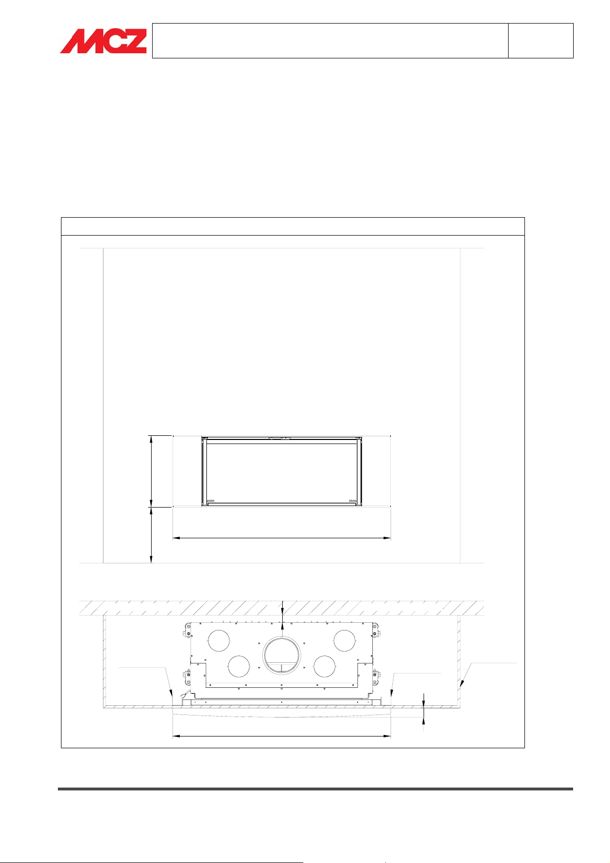
2. KLEE CLADDING WITH FIREPLACE STOVE FORMA PURO95/115
The Klee model is a recessed cladding, i.e. the fireplace stove is recessed into the wall. Therefore it is necessary
to build a counter-wall that protrudes from the perimeter wall. The depth of the wall to be constructed is at your
discretion provided you comply with all safety distances for the fireplace stove. For this purpose please refer to
Manual for Installation and Use
the
N.B. THE WALL CONSTRUCTED DURING INSTALLATION MUST BE LOAD-BEARING, EQUIPPED WITH
STEEL UPRIGHTS, POSSIBLY DOUBLE AND PLACED VERTICALLY.
KLEE FORMA PURO115 (KLEE FORM A PU RO95)
of Forma Puro95/115.
500392
1528 (1308)
PARETE PERIMETRALE PARETE PERIMETRALE
MONTANTE
ACCIAIO
50
1528 (1308)
MONTANTE
ACCIAIO
64
PARETE
D'INCASSO
Chapter 2 Servizio tecnico - Diritti riservati ad MCZ S.p.A. -
Riproduzione vietata
INSTALLATION AND USE MANUAL Chapter 3
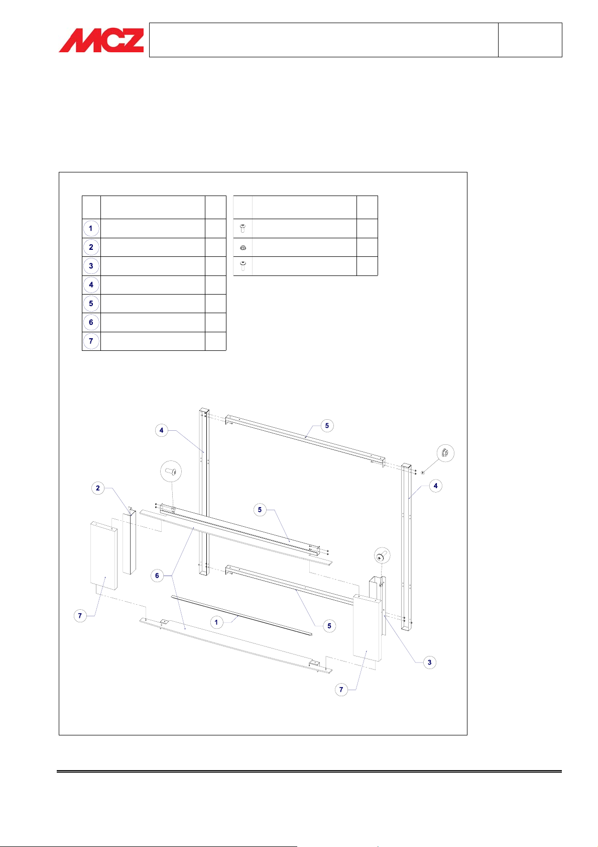
3. ASSEMBLY OF KLEE CLADDING
3.1. KLEE CLADDING COMPONENTS
KLEE
page
6
COMPONENTE
PROFILO COPRIBORDO 1
SPALLA SX
SPALLA DX
MONTANTE VERTICALE KLEE
MONTANTE ORIZZONT. KLEE
PIANO FUOCO (SUPP. CAPPA)22
SPALLE ARDESIA
N.
1
1
2
4
VITERIA IN DOTAZIONE
VITE M5X12 FOSFATATA NERA
DADO FLANGIATO FD M5
VITE AUTOPERF.PANEL.4.2X16
N.
24
30
4
Chapter 3 Technical service – all rights reserved by mcz spa
Reproduction prohibited
INSTALLATION AND USE MANUAL Chapter 3
page
KLEE
7
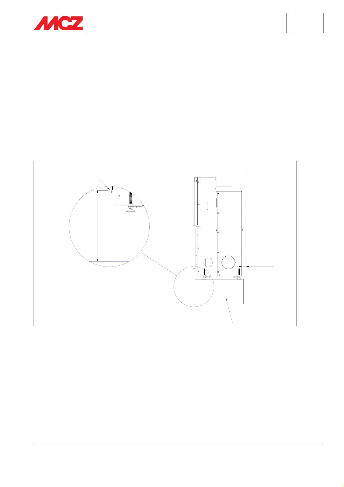
3.2. PHASE 1 - POSITIONING OF FIREPLACE STOVE FORMA PURO95/115
Place the Forma Puro in the desired position and at a safe distance from the rear wall. Raise the
fireplace stove so that the height of the edge-cover profile with respect to the floor is 400 mm (= height of fire
bed of cladding). A second adjustment of the unit (minor variations), if necessary, is made during assembly of
the cladding.
N.B. It is necessary to create a support base upon which to fasten the Puro95/115. The unit must
be firm and stable on the floor.
Install the unit Forma Puro95/115 in accordance with the instructions in the respective
and Use
and run a quick test for proper operation. If the test is successful, you can install the Klee cladding.
PROFILO
COPRIBORDO
Manual for Installation
400
DISTANZA
DI SICUREZZA
PAVIMENTO
BASE APPOGGIO
FORMA PURO
Chapter 3 Technical service – all rights reserved by mcz spa
Reproduction prohibited
INSTALLATION AND USE MANUAL Chapter 3
KLEE
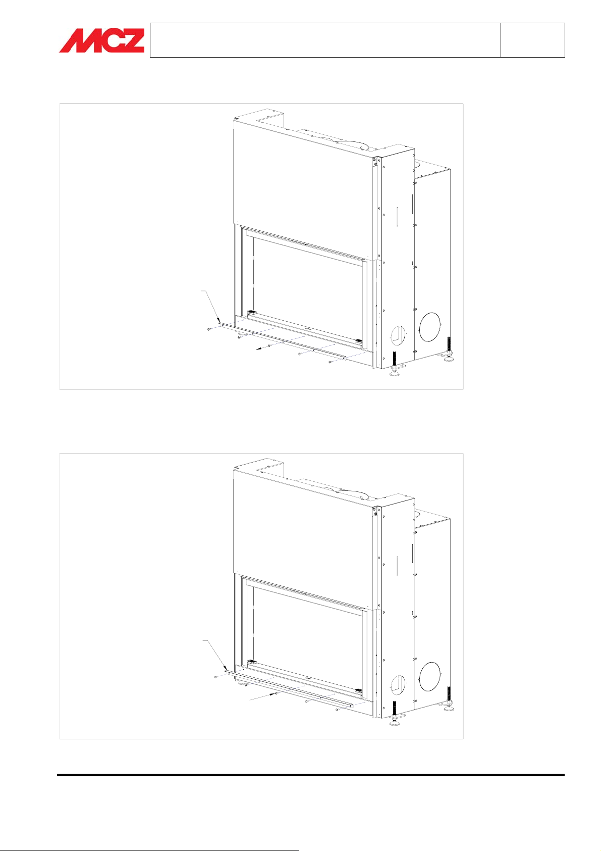
3.3. PHASE 2 – CHANGING EDGE-COVER PROFILE (element 1)
PROFILO COPRIBORDO
FORMA PURO 95(115)
page
8
Replace the edge-cover profile of the fireplace stove Forma Puro 95(115) with the edge-cover profile of the Klee
cladding (1).
PROFILO COPRIBORDO
KLEE FORMA PURO
Chapter 3 Technical service – all rights reserved by mcz spa
Reproduction prohibited

INSTALLATION AND USE MANUAL Chapter 3
page
KLEE
9
3.4. PHASE 3 - ASSEMBLY OF SIDES IN PAINTED STEEL BLACK (elements 2 and
3)
Fasten the sides (right and left) in black painted steel to Forma Puro, using °2+2 self-tapping screws. 4.2X16.
Each side must adhere perfectly to the unit and be aligned with the edge-cover profile installed in phase 2.
Chapter 3 Technical service – all rights reserved by mcz spa
Reproduction prohibited

INSTALLATION AND USE MANUAL Chapter 3
page
KLEE
10
3.5. PHASE 4 – PREPARATION OF COUNTER-WALL
Before assembling the Klee cladding, it is necessary to create the load-bearing counter-wall (or wall for recessed
installation of the fireplace stove), with an opening of W=1392 mm and H=1360 mm from the floor for the
version F/Puro115 and W=1172 mm and H=1360 mm for the version F/Puro95.
If made of fireproof plasterboard panels, it is necessary to reinforce the counter-wall with metal uprights placed
flush with the hole, vertical and resting on the floor (see drawing). For greater safety, you can use two Ushaped uprights per side (for a total of four) inserted one inside the other.
Perforate the uprights at the holes and slots in the Klee vertical upright (as in the drawing). The holes (D=5 mm)
are necessary to fasten the Klee steel frame assembled with elements 4 and 5.
N.B. It is advisable to place the counter-wall in its final position only after fastening the Klee frame
(see Phase 5)
MONTANTE
ACCIAIO
MONTANTE
ACCIAIO
1392 (1172)
1360
FORI DA
REALIZZARE
IN OPERA
MONTANTE
VERTICALE
KLEE
VISTA POSTERIORE
MONTANTE
ACCIAIO
F
O
R
A
R
M
E
O
N
T
A
N
A
T
C
E
C
I
A
I
O
Chapter 3 Technical service – all rights reserved by mcz spa
Reproduction prohibited
INSTALLATION AND USE MANUAL Chapter 3
page
KLEE
11
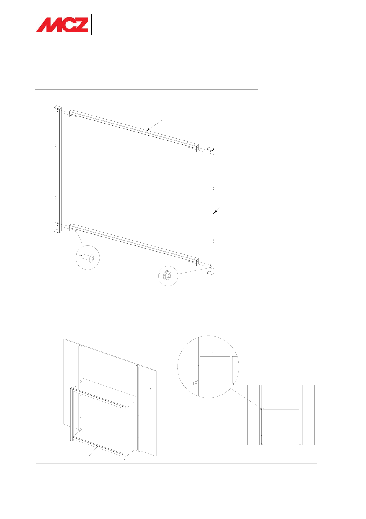
3.6. PHASE 5 - ASSEMBLY OF KLEE FRAME
Assemble two Klee vertical uprights and two Klee horizontal uprights (see drawing) using, for each hole, 1 screw
M5X12 and 1 flanged nut M5. Upon completion, the structure must be rigid.
MONTANTE
ORIZZONTALE
KLEE
MONTANTE
VERTICALE
KLEE
Fasten the Klee frame to the uprights of the counter-wall.
CONTROPARETE
TELAIO KLEE
10
Chapter 3 Technical service – all rights reserved by mcz spa
Reproduction prohibited

INSTALLATION AND USE MANUAL Chapter 3
page
KLEE
12
Place the recessed installation wall in its final location, about 76 mm from Forma Puro and with the opening
centred on the fireplace stove (see drawing). The position of the unit with respect to the counter-wall must be
precise (differences of just a few millimetres) after Phase 7 (
Assembly of Slate Shoulders)
48
.
76
SEZIONE A-A
3.7. PHASE 6 - ASSEMBLY OF FIRE BED (element 6)
Assemble element 6 (fire bed/ hood support) with element 5 (Klee horizontal upright) using 3 flanged nuts FD
M5 provided.
PIANO FUOCO
(SUPPORTO CAPPA)
MONTANTE
ORIZZONTALE
KLEE
Chapter 3 Technical service – all rights reserved by mcz spa
Reproduction prohibited

INSTALLATION AND USE MANUAL Chapter 3
page
KLEE
13
Position the fire bed thus assembled just under the edge-cover profile (element 1) and with the holes of the Klee
horizontal upright aligned with the slots of the Klee frame.
Fasten the fire bed using 1 screw M5X12 and 1 flanged nut M5 (see drawing) for each hole.
Upon completion, the black steel sides must adhere completely to the fire bed. If necessary, use the feet of
Forma Puro for precise adjustment of the height of the fireplace stove).
SPALLA ACCIAIO NERO
SPALLA IN
ACCIAIO NERO
PIANO
FUOCO
Chapter 3 Technical service – all rights reserved by mcz spa
Reproduction prohibited

INSTALLATION AND USE MANUAL Chapter 3
page
KLEE
14
3.8. PHASE 7 – ASSEMBLY OF SLATE SIDES (element 7)
Set the slate side on the fire bed so that the 2 pins of element 6 (fire bed) fit perfectly into the holes in element
6.
Each slate side must close and be aligned with the side in black painted steel.
PERNO
PERNO
3.9. PHASE 8 - ASSEMBLY OF HOOD SUPPORT (element 6)
Assemble element 6 (fire bed/ hood support) with element 5 (Klee horizontal upright) using 3 flanged nuts FD
M5 provided.
Chapter 3 Technical service – all rights reserved by mcz spa
Reproduction prohibited

INSTALLATION AND USE MANUAL Chapter 3
page
KLEE
15
Position the hood support thus assembled with the pins completely in the holes of the slate sides
Fasten the hood support to the Klee frame using 1 screw M5X12 and 1 flanged nut M5 (see drawing) for each
hole.
SPALLA
ARDESIA
SPALLA
ACCIAIO
ALLINEATE
N.B. If the slate sides move slightly, you can add a small amount of marble cement in the holes. Be
careful not to soil the rust-effect painted hood support/fire bed (the damage may be irreparable
).
Complete the counter-wall (wall for recessed installation) by insulating it at the front and top from the Forma
Puro unit.
Chapter 3 Technical service – all rights reserved by mcz spa
Reproduction prohibited

INSTALLATION AND USE MANUAL Glossary
KLEE
3.10. TECHNICAL TERMS GLOSSARY OF THE PICTURES
PAGE 5 PAGE 5
PARETE D’INCASSO WALL FOR RECESSED INSERTION
MURO PERIMETRALE PERIMETER WALL
MONTANTE ACCIAIO STEEL UPRIGHT
PAGE 6 PAGE 6
COMPONENTE COMPONENT
PROFILO COPRIBORDO EDGE-COVER PROFILE
SPALLA SX LH SIDE
SPALLA DX RH SIDE
MONTANTE VERTICALE KLEE VERTICAL UPRIGHT
MONTANTE ORIZZONT.KLEE HORIZONTAL UPRIGHT
PIANO FUOCO (SUPP.CAPPA) FIRE BED (HOOD SUPPORT)
SPALLE ARDESIA SLATE SIDES
VITERIA IN DOTAZIONE NUTS AND BOLTS PROVIDED
VITE M5X12 FOSFATATA NERA SCREW M5X12 PHOSPHATED BLACK
DADO FLANGIATO FD M5 FLANGED NUT FD M5
VITE AUTOPERFORANTE PANEL 4,2X16 SELF-TAPPING SCREW 4.2X16
PAGE 7 PAGE 7
PROFILO COPRIBORDO EDGE-COVER PROFILE
PAVIMENTO FLOOR
DISTANZA DI SICUREZZA SAFETY DISTANCE
BASE APPOGGIO FORMA PURO SUPPORT BASE FORMA PURO
PAGE 8 PAGE 8
PROFILO COPRIBORDO FORMA
PURO95(115)
PROFILO COPRIBORDO KLEE FORMA P. EDGE-COVER PROFILE KLEE FORMA P.
PAGE 10 PAGE 10
VISTA POSTERIORE REAR VIEW
MONTANTI IN ACCIAIO STEEL UPRIGHTS
FORI DA REALIZZARE IN OPERA HOLES TO BE MADE DURING INSTALLATION
MONTANTE VERTICALE KLEE VERTICAL UPRIGHT
FORARE MONTANTE ACCIAIO PERFORATE STEEL UPRIGHT
EDGE-COVER PROFILE FORMA PURO95(115)
page
16
Glossary Technical service – all rights reserved by mcz spa
Reproduction prohibited

INSTALLATION AND USE MANUAL Glossary
KLEE
PAGE 11 PAGE 11
MONTANTE VERTICALE KLEE VERTICAL UPRIGHT
MONTANTE ORIZZONT.KLEE HORIZONTAL UPRIGHT
TELAIO KLEE KLEE FRAME
CONTRO PARETE COUNTER-WALL
PAGE 12 PAGE 12
SEZIONE A-A SECTION A-A
PIANO FUOCO (SUPP.CAPPA) FIRE BED (HOOD SUPPORT)
MONTANTE ORIZZONT.KLEE HORIZONTAL UPRIGHT
PAGE 13 PAGE 13
SPALLA ACCIAIO NERO BLACK STEEL SIDE
PIANO FUOCO FIRE BED
PAGE 14 PAGE 14
PERNO PIN
PAGE 15 PAGE 15
SPALLA ACCIAIO STEEL SIDE
SPALLA ARDESIA SLATE SIDE
ALLINEATE ALIGNED
PARETE D’INCASSO WALL FOR RECESSED INSERTION
page
17
Glossary Technical service – all rights reserved by mcz spa
Reproduction prohibited
 Loading...