


EN
INSTALLATION AND USE
MANUAL
8901158500
INSTALLATION AND USE MANUAL
Contents
page
2
MCZ GROUP S.p.A. - Via La Croce 8, I - 33074 Vigonovo di Fontanafredda (PN) Italy.
09
EN 13229:2001, A 1:2003,
HY DROTHERM 80
Potencia nominal:
Potência nominal:
Nominal heat output:
Brændværdi:
E misió n CO ( al 13% de O2) :
E missão CO ( 13% de O 2) :
CO emission ( at 13% O2)
CO emissi on (ved 13% O2):
Eficiencia:
Eficiencia:
Efficiency:
Virkningsgrad:
Temperadura humos:
Tempretura dos fumos:
Flue gas temperature:
Røggastemperatur:
Distan cias de seg urid ad (retro):
Distan cia de seg urança (t rasiera):
Safety clarence distan ce ( back):
Sikkerhedsaf st and (bag):
Distan cias de seg urid ad (l ater ales):
Distan cia de seg urança (lateral ):
Safety cl arence di st ance (side):
Sikkerhedsaf st and (side):
Presión máxima de agua:
Pressão máxima da água:
Permi ssibl e max. water pressu re:
Max. vandtryk:
Producto conforme a la instalación de tubos múltiples. Produto conforme
para instalação em condutas multiplas. Appliance suitable for installation in
a shared flue. Apparatet kan bruges i en røggassamleledning.
Aparato de funcionamiento intermitente. Aparelho com funcionamento
intermitente . Intermitte ntly operating unit. Apparat me d inte r mitterende
funktion.
Utilizar sólo con combustibles adaptados. Utilizar somente combustivel
adaquado. U se only recommended fuels. Anvend kun anbefalede
brændsler.
Leer y se guir las instrucciones! Leia atentamente e siga a s
instruções! Read and follow the operating instructions! Følg
fabrika ntens brugervejl edni ng!
CO D : 8901028600
HY DRO T HERM 80E
26,2 kw
(15,2 kW H
0,61%
77,1%
333°C
180 mm
180 mm
1,5 bar
(150 kPa)
2
O)
Contents Technical service – MCZ GROUP S.p.A. all rights reserved - Reproduction prohibited
INSTALLATION AND USE MANUAL
Contents
page
3
MCZ GROUP S.p.A. - Via La Croce 8, I - 33074 Vigonovo di Fontanafredda (P N) Italy.
09
EN 13229:2001, A 1:2003,
HYDROTHERM 70
HY DROTHERM 70DX
Potencia nominal:
Potência nominal:
Nominal heat output:
Brændværdi:
Emisión CO ( al 13% de O2):
E missão CO (13% de O2):
CO emission (at 13% O2)
CO emission (ved 13% O2):
Eficiencia:
Eficiencia:
Efficiency:
Virkningsgrad:
Temp erad ura hu mo s:
Temp retura do s f u mos:
Flue gas temperature:
Røggastemperatur:
Distanci as de seguridad ( ret ro):
Distanci a de segurança (trasiera) :
Safety claren ce d istance (back):
Sikkerh edsafstand (bag ):
Distanci as de seguridad ( laterales):
Distanci a de segurança (lateral):
Safety claren ce d istance (side):
Sikkerh edsafstand (side):
Presión máxima de agua:
Pressão máxima da ág ua:
Permissible max. water pressure:
Max. vand t ryk:
Producto conforme a la instalación de tubos múltiples. Produto conforme
para instalação em condutas multiplas. Appliance suitable for installation in
a shared flue. Apparatet kan bruges i en røggassamleledning.
Aparato de f uncionamie nto interm ite n te. Aparelho com funcioname nto
interm itente . Intermittently operating unit. Apparat med inte rmitter e nde
funktion.
Utilizar só lo con combustibles adaptados. Utilizar somente combustivel
adaquado. Use only recommended fuels. Anvend kun anbefalede
brændsler.
Lee r y seguir las instruccione s! Leia a tenta m e nte e siga a s
instruções! Read and follow the operating instructions! Følg
fabrikantens brugervejledni ng!
HY DROTHERM 7 0S X
COD : 8901028400
21,2 kw
(13,0 kW H
0,87%
75,2%
310°C
150 mm
150 mm
1,5 bar
(150 kPa)
2
O)
MCZ GROUP S.p.A. - Via La Croce 8, I - 33074 Vigonovo di Fontanafredda (PN) Italy.
09
EN 13229:2001, A1:2003,
HYDRO T HERM 70 V
Potencia nominal:
Potência nominal:
Nominal heat output:
Brændværdi:
E misió n CO ( al 13% de O2):
Emissão CO (13% de O2):
CO emissi on (at 13% O2)
CO emissi on (ved 13% O2):
Eficiencia:
Eficiencia:
Efficiency:
Virkningsgrad:
Temperadura humos:
Tempretura dos fumos:
Flu e gas temperature:
Røggastemperatur:
Distancias de segurid ad ( ret ro):
Distancia de segurança (t rasiera):
Safety claren ce distance (back):
Sikkerhedsafst and (b ag):
Distancias de segurid ad (lat erales):
Distancia de segurança (lateral) :
Safety claren ce distance (sid e) :
Sikkerhedsafst and (si de):
Presión máxima de agua:
Pressão máxima da água:
Permissibl e max. water pressure:
Max. vandtry k:
Producto conforme a la instalación de tubos múltiples. Produto conforme
para instalação em condutas multiplas. Appliance suitable for installation in
a shared flue. Apparatet kan bruges i en røggassamleledning.
Aparato de funcionamiento intermite nte. Aparelho com funcionamento
interm itente. Intermittently operating unit. Apparat med interm itte r e nde
funktion.
Utilizar sólo con combustibles adaptados. Utilizar somente combustivel
adaqua do. Use only recommended fuels. Anvend kun anbefalede
brændsler.
Leer y seguir las instrucciones! Leia atentamente e siga as
instruções! Read and follow the operating instructions! Følg
fabrikantens brugervejledning!
COD : 8901028500
21,2 kw
(13,0 kW H
0,87%
75,2%
310°C
150 mm
150 mm
2,0 bar
(200 kPa)
2
O)
Contents Technical service – MCZ GROUP S.p.A. all rights reserved - Reproduction prohibited

INSTALLATION AND USE MANUAL
Contents
page
4
INTRODUCTION .................................................................................................................................... 6
1. WARNINGS AND WARRANTY CONDITIONS ..................................................................................... 7
1.1. SAFETY WARNINGS ........................................................................................................................ 7
1.2. OPERATING WARNINGS .................................................................................................................. 7
1.3. WARRANTY CONDITIONS ................................................................................................................ 7
1.3.1. Restrictions .............................................................................................................................. 8
1.3.2. Exclusions ................................................................................................................................ 8
1.4. IMPORTANT INFORMATION FOR CORRECT DISPOSAL OF THE PRODUCT IN ACCORDANCE WITH EC
DIRECTIVE 2002/96/EC ............................................................................................................................. 8
2. INSTALLATION IN ACCORDANCE WITH UNI 10683 ......................................................................... 9
2.1. OPERATING AREA ........................................................................................................................... 9
2.2. PRECAUTIONS ................................................................................................................................ 9
2.3. CONNECTION TO THE EXTERNAL AIR INTAKE ................................................................................ 10
2.4. CONNECTION TO THE FLUE PIPE ................................................................................................... 11
2.4.1. Smoke valve (optional) ........................................................................................................... 11
2.5. FLUE PIPE .................................................................................................................................... 11
2.5.1. Examples of flue pipes ............................................................................................................ 12
2.6. COWL .......................................................................................................................................... 13
3. DIMENSIONS AND TECHNICAL SPECIFICATIONS .......................................................................... 14
4. INSTALLATION AND ASSEMBLY ...................................................................................................... 17
4.1. PREPARATION AND UNPACKING .................................................................................................... 17
4.2. POSITIONING ............................................................................................................................... 17
4.3. HEIGHT ADJUSTMENT .................................................................................................................. 18
4.4. RELEASE OF COUNTERWEIGHTS ................................................................................................... 18
4.5. MCZ CONTROL UNIT CONNECTION ................................................................................................ 19
4.5.1. The control unit MCZ .............................................................................................................. 19
4.5.2. Electrical connection of the control unit MCZ ............................................................................. 20
4.5.3. Operation of the control unit MCZ ............................................................................................ 21
4.6. PLUMBING CONNECTION .............................................................................................................. 23
4.6.1. Water characteristics .............................................................................................................. 23
4.6.2. Hydraulic connection with Open Tank ...................................................................................... 24
4.6.3. Hydraulic connection with Closed Tank ..................................................................................... 24
4.7. HYDRAULIC DIAGRAMS ................................................................................................................. 25
4.7.1. Diagram 1 OPEN TANK (KIT 1 OPEN TANK) .............................................................................. 25
4.7.2. Diagram 2 OPEN TANK (KIT 2 OPEN TANK) .............................................................................. 26
4.7.3. Diagram 3 OPEN TANK (KIT 3 OPEN TANK) .............................................................................. 27
4.7.4. Diagram 1 CLOSED TANK (KIT 1 CLOSED TANK) ...................................................................... 28
4.7.5. Diagram 2 CLOSED TANK ........................................................................................................ 29
4.8. THERMAL SAFETY DISCHARGE VALVE FOR CLOSED TANK CIRCUIT (HYDROTHERM 70V) ................. 30
4.8.1. Function ................................................................................................................................ 30
4.8.2. Technical specifications ........................................................................................................... 30
4.8.3. Installation ............................................................................................................................ 31
4.8.4. Maintenance .......................................................................................................................... 32
4.8.5. Safety ................................................................................................................................... 32
4.9. INSTALLATION KIT ....................................................................................................................... 33
4.9.1. Kit 1 OPEN TANK .................................................................................................................... 33
4.9.2. Kit 2 OPEN TANK .................................................................................................................... 34
4.9.3. Kit 3 OPEN TANK .................................................................................................................... 34
4.9.4. Kit 1 CLOSED TANK ................................................................................................................ 35
4.9.5. Kit 2 CLOSED TANK ................................................................................................................ 35
4.10. UNIT CLADDING ........................................................................................................................ 36
4.10.1. INSULATION OF FIREPLACE STOVE ...................................................................................... 36
4.10.2. INSULATING A WOODEN BEAM ............................................................................................ 36
Contents Technical service – MCZ GROUP S.p.A. all rights reserved - Reproduction prohibited

INSTALLATION AND USE MANUAL
Contents
page
5
4.10.3.
Decorative hood .................................................................................................................. 36
5. OPERATION ..................................................................................................................................... 37
5.1. PRE-LIGHTING WARNINGS ............................................................................................................ 37
5.2. OPERATING TEST ......................................................................................................................... 37
5.3. CHOICE OF FUEL .......................................................................................................................... 39
5.4. LOADING THE FUEL ...................................................................................................................... 39
HEAT POWER ....................................................................................................................................... 39
KCAL/H ................................................................................................................................................ 39
5.5. CONTROL OF COMBUSTION .......................................................................................................... 40
5.6. FIRST LIGHTING .......................................................................................................................... 40
5.7. EMERGENCY SITUATIONS ............................................................................................................. 41
6. MAINTENANCE AND CLEANING ...................................................................................................... 42
6.1. CLEANING TO BE PERFORMED BY THE USER .................................................................................. 42
6.1.1. Cleaning the glass .................................................................................................................. 42
6.1.2. Cleaning the exchanger .......................................................................................................... 42
6.1.3. Cleaning out the ashes ........................................................................................................... 42
6.1.4. Cleaning flue pipe ................................................................................................................... 43
6.1.5. Lubrication and routine maintenance of the extensible guides .................................................... 43
7. DOOR ADDITIONAL WEIGHT KIT .................................................................................................... 44
7.1. Supplementary weight kits for door closure (only available for closed tank version) ............................ 44
Contents Technical service – MCZ GROUP S.p.A. all rights reserved - Reproduction prohibited

INSTALLATION AND USE MANUAL
INTRODUCTION
Dear customer,
Thank you for choosing an MCZ product, specifically a
fireplace stove of the Forma line.
We are sure that, with use, you will appreciate the
quality of an attentively designed and tested product.
Our goal is to combine technology with easy use and,
above all, safety.
For best fireplace stove operations and to fully
enjoy the heat and sense of well being it will
spread throughout your home, we suggest you
carefully read this booklet before use. Please
contact your dealer for full assistance in
resolving any doubts or problems.
Congratulations on your choice and remember, the
fireplace stove MUST NEVER be used by children
who should always be kept at a safe distance!
Revisions to the publication
In order to improve the product, the Manufacturer
reserves the right to modify and update this
publication without prior notice.
Reproduction, even partial, of this manual without the
Manufacturer's authorisation is prohibited.
Manual preservation
Please take care of this manual and keep it in a
place that can be quickly and easily reached.
If this manual should be lost or destroyed, or if it
is in poor condition, ask for a copy from your
retailer or directly from the manufacturer,
providing product identification data.
How to read the manual
An essential item or one that requires specific
attention is published in “bold”.
“Italics"
NOTE: the “NOTE” provides the reader with
additional information on the subject.
are used for any additional clarification.
Chapter 1
page
6
These symbols signal specific messages
in this booklet
WARNING:
This warning symbol found in various
points in this manual indicates that the
user should carefully read and understand
the message to which it refers since
neglect to follow these instructions
could cause serious fireplace stove
damage or injury to the user.
INFORMATION:
This symbol intends to emphasise
important information for good fireplace
stove operations. Failure to observe these
instructions could jeopardise product use
and operations may be unsatisfactory
Introduction Technical service – MCZ GROUP S.p.A. all rights reserved - Reproduction prohibited

INSTALLATION AND USE MANUAL
1. WARNINGS AND WARRANTY
CONDITIONS
1.1. SAFETY WARNINGS
Installation, electrical connection,
functional check and maintenance of this
appliance must only be performed by
qualified or authorised personnel.
Install the closed fireplace in compliance
with the applicable regulations in force in
the place, region or country.
This appliance must not be used by anyone
(including children) with limited physical,
sensory or mental skills or with little
experience and knowledge, unless they are
supervised or have been instructed to use
the device by the person in charge of its
safety.
Only use the fuel recommended by MCZ.
The appliance must not be used as an
incinerator. The use of liquid fuel is strictly
forbidden.
For correct use of the fireplace stove and
accessories, and to prevent accidents, always
follow the instructions in this booklet.
Before beginning any operation, anyone who
uses the stove must read and understand the
entire contents of this instruction booklet.
The fireplace stove must be used only for its
intended purpose. Any other use is considered
improper and therefore hazardous.
Check the conditions of the surface that will
support the weight of the stove. If it is made of
flammable material such as wood, carpet, or
plastic, provide suitable insulation.
Avoid installation in rooms with B type gas
devices, hoods with or without exhaust, heat
pumps, collective ventilation conduits.
Do not install several flue pipes in one room, and
avoid having a stairwell in the vicinity. Check that
in adjacent connected room there are not any
units whose simultaneous use would create
negative pressure in one of the two rooms.
The user is fully liable for improper product use,
releasing MCZ from any civil or penal liabilities.
Any tampering with the fireplace stove, or use of
non-original spare parts, may be hazardous to
the user and releases MCZ from any civil or penal
liability.
Parts of the surfaces of the fireplace stove are
very hot (door, handle, glass). Therefore, avoid
direct contact with these parts unless wearing
protective clothing or specific means such as, for
Chapter 1
page
7
example, heat protective gloves or "cold"
activation devices.
Incorrect installation or poor maintenance (not
compliant with the provisions of this manual)
may cause damages to persons, animals or
property. MCZ is not civilly or criminally liable in
these cases.
1.2. OPERATING WARNINGS
Turn off the fireplaces stove in the event of faults
or poor operations.
Never place flammable materials closer than 150
cm to the fireplace stove.
If the chimney flue draught is poor (due to bad
weather or improper installation), start the fire
decisively while keeping the door slightly ajar.
When you close the door, keep the air register
completely open. Use small pieces of dry wood.
If combustion problems continue, please contact
a specialized technician.
Install the fireplace stove in a location which is
suitable for fire fighting, and equipped with all
services such as air, water and electricity supply
and smoke discharge.
Do not light the fire with flammable materials.
To clean the appliance's chimney, remove the
smoke deflector. To remove it correctly, lift the
front and at the same time slide it forward in
order to free it from rear support.
INFORMATION:
For any problem, please contact your dealer or
MCZ qualified and authorised personnel and
always request original spare parts for repairs.
Check and periodically clean the smoke exhaust
stack as foreseen by current regulations in the
country of installation.
If there is a fire in the flue pipe, keep the door of
the fireplace stove and the combustion air
register closed at all times. Request assistance
from the competent authorities.
Carefully conserve the instruction booklet. It
must remain with the fireplace stove for its entire
life cycle. If the stove is sold or transferred to
another user, make sure the manual
accompanies the product.
If lost, please request a copy from your dealer or
from MCZ.
1.3. WARRANTY CONDITIONS
MCZ guarantees the product, except for the
elements subject to normal wear listed below, for
Warnings and warranty conditions Technical service – MCZ GROUP S.p.A. all rights reserved - Reproduction prohibited
INSTALLATION AND USE MANUAL
two years from the date of purchase proven by a
document that indicates the dealer's name and date
of sale, if the completed warranty certificate was
returned within 8 days and if the product was
installed and inspected by a specialised installation
technician and according to the detailed instructions
indicated in the instruction manual supplied with the
product.
The warranty includes the free replacement or repair
of parts recognised as factory defective.
1.3.1. Restrictions
The above guarantee does not cover components
relating to electrical parts, on which the guarantee
period is 1 year from the purchase of the product,
documented as specified above. The warranty does
not cover parts subject to normal wear such as:
gaskets, glass, and all removable fire box parts.
Replaced parts will be guaranteed for the remaining
warranty period from the date of product purchase.
Specifically, glass is guaranteed from
the moment the MCZ installation
technician certifies its integrity when
installation is completed.
1.3.2. Exclusions
The warranty does not cover any part that may
be defective due to negligence or careless use,
incorrect maintenance, installation non
compliant with that specified by MCZ (see
relevant chapters in this manual).
MCZ refuses to accept any responsibility for any
damage which may be caused, directly or indirectly,
by persons, animals or things as a result of the failure
to observe all the provisions set forth in the
instruction booklet, especially those concerning
warnings on the subject of installation, use and
maintenance of the appliance.
In the event of product inefficiency, please contact
your dealer and/or area importer.
Damages caused by transport and handling are not
covered by the warranty.
Exclusively refer to the supplied manual for product
installation and use.
The warranty is null and void in the event of damage
due to tampering, weather, natural calamities,
lightening, fire, defective electrical and hydraulic
systems and the lack or incorrect maintenance as per
the manufacturer's instructions.
SERVICE REQUESTS
Service requests must be addressed
to the dealer who shall forward the
request to MCZ technical assistance.
Chapter 1
page
8
MCZ is not liable in the event the
product and any other accessory is
improperly used or modified without
authorisation.
Only original MCZ spare parts must be
used for all replacements.
1.4. IMPORTANT INFORMATION FOR
CORRECT DISPOSAL OF THE PRODUCT
IN ACCORDANCE WITH EC DIRECTIVE
2002/96/EC
.
At the end of its working life, the product must not be
disposed of as urban waste.
It must be taken to a special local authority
differentiated waste collection centre or to a dealer
providing this service.
Disposing of a appliance separately avoids possible
negative consequences for the environment and
health deriving from inappropriate disposal and
enables the constituent materials to be recovered to
obtain significant savings in energy and resources.
As a reminder of the need to dispose of appliances
separately, the product is marked with a crossed-out
wheeled dustbin.
Warnings and warranty conditions Technical service – MCZ GROUP S.p.A. all rights reserved - Reproduction prohibited

INSTALLATION AND USE MANUAL
2. INSTALLATION IN ACCORDANCE WITH UNI
10683
2.1. OPERATING AREA
For good operations and good heat distribution, the fireplace stove
should be positioned in a place where the air required for combustion
can flow (at least 60 m
standards and current regulations in the country of installation.
The room volume must not be less than 60 m
Air must enter through permanent apertures on the walls (near the
fireplace stove) that open outdoors with a minimum section of 360 cm
These apertures (air vents) must be made so as not to be obstructed in
any way.
Air can also be taken from adjacent rooms as long as these are
equipped with outdoor air vents and not bedrooms or bathrooms or
rooms where fire hazards do not exist such as garages, wood sheds,
flammable material warehouses, strictly observing the provisions of
current regulations.
Fireplace stoves may not be installed in
bedrooms, bathrooms and where another
heating device is installed without autonomous
air flow (fireplace, stove, etc.).
Placing the fireplace stove in explosive
environments is prohibited.
The floor of the room where the fireplace stove
is to be installed must be strong enough to
support its weight.
In the event of wood floors, install a protective
covering in accordance with current regulations
in the country of installation.
If walls are not flammable, install the fireplace
stove at least 5 cm from the walls.
3
/h must be available) according to installation
3
.
2
.
Chapter 2
page
9
2.2. PRECAUTIONS
The fireplace stove must be installed in a suitable surface that permits
routine opening and maintenance operations.
The room must be:
suitable for room operating conditions
equipped with power supply 230V 50 Hz
equipped with an adequate smoke exhaust system
equipped with outdoor ventilation
provided with an earth connection complying with CEI 64-8
Theoretical notions for installation Technical service – MCZ GROUP S.p.A. all rights reserved - Reproduction prohibited
INSTALLATION AND USE MANUAL
IMPORTANT!
The fireplace stove must be installed and
assembled by qualified personnel.
The fireplace stove must be connected to a flue
pipe or other vertical smoke stack that can
discharge smoke at the highest point of the
house.
The fireplace stove must be connected to a flue
pipe or an internal or external vertical duct
conforming to current standards UNI 7129 7131 9615.
Smoke is generated from burning wood and,
therefore, may dirty adjacent or nearby walls.
Before positioning the fireplace stove, you must
make a hole for the intake of external air.
2.3. CONNECTION TO THE EXTERNAL AIR INTAKE
Chapter 2
page
10
The room where the stove is installed must have at least as much air as
requested by normal combustion of the equipment and by room
ventilation. This may take place through permanent apertures in the
room walls that lead directly outdoors or ventilated rooms according to
UNI 10683.
For this purpose, drill a hole with minimum 360 cm² free section near
the fireplace stove (22 cm diameter or a 20x18cm rectangle), protected
by an indoor and outdoor grille.
The air intake must also:
directly communicate with the installation room
be protected by a grill, made of metallic anti-insect mesh or a
suitable protection as long as it does not reduce the minimum
section.
be installed so as to avoid obstruction
for ducts, up to 3.5 linear metres, increase the section by about
5% while increased by 15% for larger measurements.
Remember that the ventilation grills always have a cm
2
useful section on one side. When selecting the grill and hole
dimension, make sure the useful grill section is greater than
or equal to the section required by MCZ for product
operations.
Connecting the air outlet directly to the fireplace stove is not
mandatory but the above mentioned section must guarantee
about 50 m³/h of air. See standard UNI 10683.
IMPORTANT!
Air flow may also be obtained from a room adjacent
to the installation room as long as this flow is free
through permanent apertures that directly
communicate with the outdoors; avoid air outlets
connecting with heating units, garages, kitchens or
bathrooms.
Theoretical notions for installation Technical service – MCZ GROUP S.p.A. all rights reserved - Reproduction prohibited
INSTALLATION AND USE MANUAL
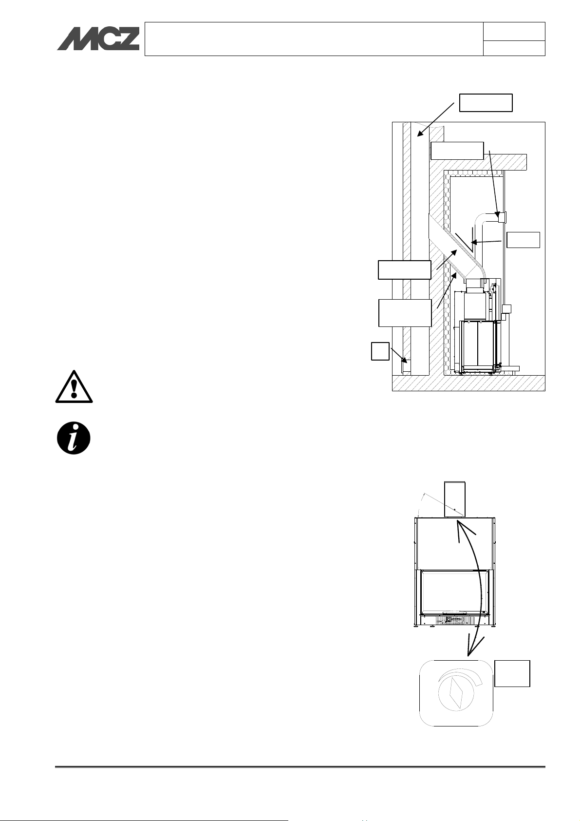
2.4. CONNECTION TO THE FLUE PIPE
Chapter 2
page
11
The connection to the flue pipe is a very important element. The
connection must be made with a great deal of care; in the event of
erroneous or anomalous construction, it is extremely difficult to remedy
without damaging the hood liner. In addition, the connection is made in
a part of the stove where temperatures are very high, and for this
reason it is important to use materials that are capable of resisting heat
and also the acidity of the fumes produced by combustion.
Before beginning work, please note the following:
The connecting pipe must have a maximum slope of 45
degrees. This is to avoid excessive deposit of condensation
produced in the initial phases of lighting the fireplace stove,
and/or the excessive accumulation of creosote. It also keeps
the release of smoke from being slowed down.
The unions must be made of metal and suitable for the
specific operating conditions of the product and marked
EC (EN1856-2). The use of flexible and extending metal
pipes is not permitted.
The components making up the connecting pipe must be
perfectly sealed.
The joint to the flue pipe must not be too long (to avoid
obstructions), nor too short (to avoid smoke leakage).
If metal connecting pipes are used, they must be
insulated with suitable material such as ceramic fibre
matting, to avoid deterioration of the masonry and of
the decorative hood liner.
IMPORTANT!
Any increase in the section of the connecting pipe
must start immediately above the hood of the
fireplace and not along the flue pipe section.
Flue pipe
Hood grille
45° max
Smoke
Ceramic fibre
insulation
A
Example of fireplace stove connection in
flue chimney
Illustration of a correctly constructed
chimney flue with a chamber and sealed
door (A) for solid combustion product
collection and discharge at the foot of the
external ascending segment.
2.4.1. Smoke valve (optional)
30°
In case of excessive draught in the flue chimney, combustion may
become unbalanced and consequently less efficient. In this case, in
order to improve combustion efficiency, it is advisable to install the
smoke valve (optional) directly at the output of the fireplace stove. If
you wish to position the control knob (B in the figure) at the front of
the product, it is necessary to place a 25 cm extension of the smoke
duct between the fireplace stove and the valve.
2.5. FLUE PIPE
The flue pipe is a fundamental element in discharging smoke and
therefore must have the following requisites:
It must be waterproof and thermally insulated.
It must be made with heat resistant materials, resistant to
combustion products and any condensation.
have a vertical arrangement with deviations from the axis of
no more than 45° and without kinks.
must be suitable for the specific operating conditions of the
Smoke valve
product and marked EC (EN1856-1, EN1443).
Theoretical notions for installation Technical service – MCZ GROUP S.p.A. all rights reserved - Reproduction prohibited
B
INSTALLATION AND USE MANUAL
must be suitably sized to accommodate the draught/smoke
disposal requirements necessary for the correct functioning of
the product (EN13384-1).
It must preferably have a circular interior section.
If pre-existing and previously used, it must be cleaned.
The flue pipe is of primary importance for the correct
functioning and safety of your fireplace stove.
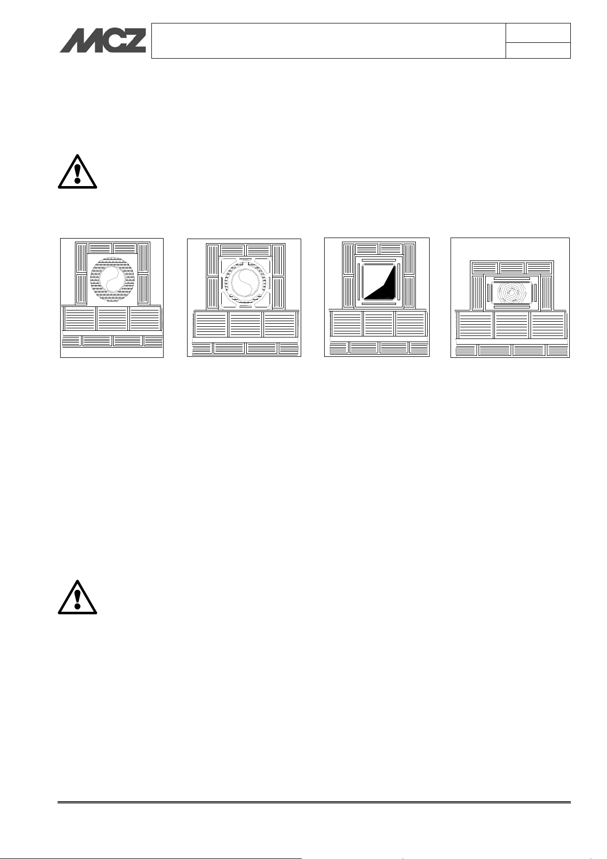
2.5.1. Examples of flue pipes
Stainless steel 316 flue
pipe with dual chamber
insulated with ceramic wool
or equivalent resistant to
400°C.
EXCELLENT
Flue pipe in refractory brick
with insulated double wall and
external coat of cement mix
lightened with honeycomb
material such as clay.
GOOD
Traditional square section
clay flue pipe with insulating
hollow inserts.
GOOD
Square or rectangular section flue pipes must have rounded internal
corners with radius not less than 20mm. For the rectangular section,
the ratio between internal dimensions must be ≤1.5.
The sections/lengths of the flue pipe shown in the technical data table
are guidelines for correct installation. Any alternative configurations
must be suitably sized in accordance with EN13384-1.
The smoke duct should be equipped with a solid material collection
chamber at the mouth of the smoke duct to be easily opened with an
airtight door.
IMPORTANT !
In the event of doubt on your chimney flue
operations or that its dimensions are different from
those recommended, we highly suggest an
authorised MCZ technician inspect and measure
chimney flue performance (micro-gauge
measurements)
MCZ s.p.a. shall not be held liable for poor operation
of the fireplace stove that is due to a flue pipe of
improper size or installation that does not comply
with provided requirements.
Chapter 2
page
12
Avoid flue pipes with internal
rectangular sections whose
larger side is double the smaller
such as 20x40 or 15x30.
AVERAGE
Theoretical notions for installation Technical service – MCZ GROUP S.p.A. all rights reserved - Reproduction prohibited
INSTALLATION AND USE MANUAL
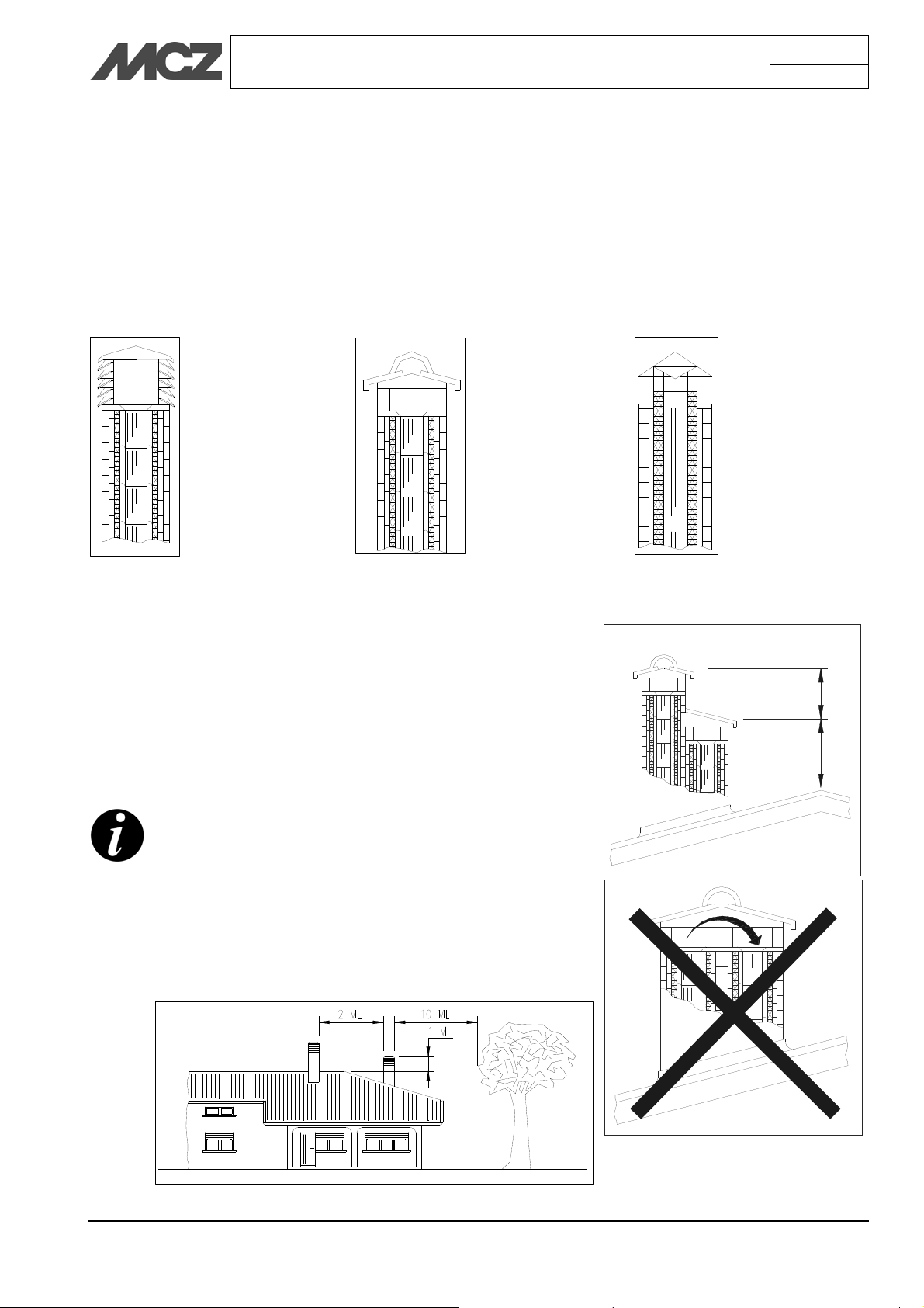
2.6. COWL
If underestimated, it is a severe impediment to correct "chimney
system" operations.
Flue pipe draught also depends on its cowl.
Therefore, if hand made, its four exhaust sections must correspond to
more than twice the internal section of the flue pipe.
Having to exceed the peak of the roof, the cowl will be
exposed to wind, therefore an industrial type is recommended.
An industrial cowl,
with prefabricated
sections fitting
together, allows
optimal disposal of
the flue gases.
The cowl must meet the following requisites:
It must have an internal section equal to that of the chimney.
It must have a useful output section not less that double that
of the internal section of the flue pipe.
It must be built to prevent rain, snow and any foreign objects
from getting into the flue pipe.
They must be installed to guarantee adequate smoke
dispersion and out of the reflux area where negative pressure
forms.
For paired flue pipes, the cowl for solid combustion
and the one for the upper floor must be at least 50cm
higher than the other to avoid pressure transfers
between paired flues.
The cowl must not have obstacles within 10 m such as
walls, roof slopes and trees. Otherwise, raise it at least
1 m over the obstacle and, in the event of other
nearby cowls, keep them at least 2 m away. In any
case, the cowl must exceed the peak of the roof by at
least 1m.
A traditional
handmade cowl.
The right exhaust
section must be at
least twice the
internal section of
the flue pipe, 2.5
times is ideal.
Chapter 2
page
13
Steel cowl for flue pipe
with internal smoke
deflector cone.
t
m
5
,
0
t
m
1
Theoretical notions for installation Technical service – MCZ GROUP S.p.A. all rights reserved - Reproduction prohibited
INSTALLATION AND USE MANUAL
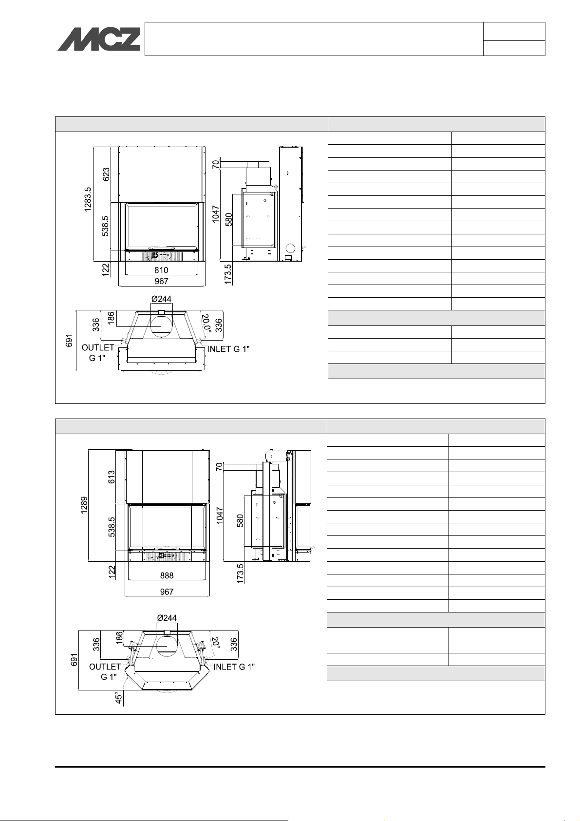
3. DIMENSIONS AND TECHNICAL SPECIFICATIONS
HYDRO THERM 80 Technical specifications
Fuel type Wood
Hourly consumption 7,1 kg/h
Nominal thermal power kW 26,2 - Kcal 22.532
H2O thermal power kW 15,2 - Kcal 13.072
Efficiency 77,1%
Heatable volume * 563/40-644/35-751/30
Recommended draught 12 Pa / 0,12 mbar
Smoke temperature 333 °C
Smoke outlet Ø 25 cm
Net weight 232 Kg
External combustion air outlet cm² 200
CO emission in smoke (13 %O2) 0,61%
Massive smoke capacity 17,7 g/s
Permissible max. water pressure 1,5 bar
Flue pipe
Up to 5 m 30x30 cm Ø30
Over 5 m 25x25 cm Ø25
Note
Intermittent combustion unit
* Data may vary according to the fuel used
HYDRO THERM 80E Technical specifications
Fuel type Wood
Hourly consumption 7,1 kg/h
Nominal thermal power kW 26,2 - Kcal 22.532
H2O thermal power kW 15,2 - Kcal 13.072
Efficiency 77,1%
Heatable volume * 563/40-644/35-751/30
Recommended draught 12 Pa / 0,12 mbar
Smoke temperature 333 °C
Smoke outlet Ø 25 cm
Net weight 235 Kg
External combustion air outlet cm² 200
CO emission in smoke (13 %O2) 0,61%
Massive smoke capacity 17,7 g/s
Permissible max. water pressure 1,5 bar
Flue pipe
Up to 5 m 30x30 cm Ø30
Over 5 m 25x25 cm Ø25
Note
Intermittent combustion unit
* Data may vary according to the fuel used
Chapter 3
page
14
Dimensions and technical specifications Technical service – MCZ GROUP S.p.A. all rights reserved - Reproduction prohibited

INSTALLATION AND USE MANUAL
HYDRO THERM 70 Technical specifications
Fuel type Wood
Hourly consumption 6,5 kg/h
Nominal thermal power Kw 21,2 - Kcal 18.232
H2O thermal power kW 13,0 - Kcal 11.180
Efficiency 75,2 %
Heatable volume * 456/40-521/35-608/30
Recommended draught 12 Pa / 0,12 mbar
Smoke temperature 310 °C
Smoke outlet Ø 20 cm
Net weight 195 Kg
External combustion air outlet cm² 200
CO emission in smoke (13
%O
)
2
Massive smoke capacity 14,4 g/s
Permissible max. water
pressure
Flue pipe
Up to 5 m 25x25 cm Ø25
Over 5 m 20x20 cm Ø20
Note
Intermittent combustion unit
* Data may vary according to the fuel used
HYDRO THERM 70V Technical specifications
Fuel type Wood
Hourly consumption 6,5 kg/h
Nominal thermal power kW 21,2 - Kcal 18.232
H2O thermal power kW 13,0 - Kcal 11.180
Efficiency 75,2 %
Heatable volume * 456/40-521/35-608/30
Recommended draught 12 Pa / 0,12 mbar
Smoke temperature 310 °C
Smoke outlet Ø 20 cm
Net weight 212 Kg
External combustion air outlet cm² 200
CO emission in smoke (13
%O
)
2
Massive smoke capacity 14,4 g/s
Permissible max. water
pressure
Flue pipe
Up to 5 m 25x25 cm Ø25
Over 5 m 20x20 cm Ø20
Note
Intermittent combustion unit
* Data may vary according to the fuel used
Chapter 3
page
15
0,87%
1,5 bar
0,87%
2,0 bar
Dimensions and technical specifications Technical service – MCZ GROUP S.p.A. all rights reserved - Reproduction prohibited

INSTALLATION AND USE MANUAL
HYDRO THERM 70SX Technical specifications
Fuel type Wood
Hourly consumption 6,5 kg/h
Nominal thermal power kW 21,2 - Kcal 18.232
H2O thermal power kW 13,0 - Kcal 11.180
Efficiency 75,2 %
Heatable volume * 456/40-521/35-608/30
Recommended draught 12 Pa / 0,12 mbar
Smoke temperature 310 °C
Smoke outlet Ø 20 cm
Net weight 204 Kg
External combustion air outlet cm² 200
CO emission in smoke (13
)
%O
2
Massive smoke capacity 14,4 g/s
Permissible max. water
OUTLET
G 1"
INLET G 1"
pressure
Flue pipe
Up to 5 m 25x25 cm Ø25
Over 5 m 20x20 cm Ø20
Note
Intermittent combustion unit
* Data may vary according to the fuel used
HYDRO THERM 70DX Technical specifications
Fuel type Wood
Hourly consumption 6,5 kg/h
Nominal thermal power kW 21,2 - Kcal 18.232
H2O thermal power kW 13,0 - Kcal 11.180
Efficiency 75,2 %
Heatable volume * 456/40-521/35-608/30
Recommended draught 12 Pa / 0,12 mbar
Smoke temperature 310 °C
Smoke outlet Ø 20 cm
Net weight 204 Kg
External combustion air outlet cm² 200
CO emission in smoke (13
%O
)
2
Massive smoke capacity 14,4 g/s
INLET G 1"
OUTLET
G 1"
Permissible max. water
pressure
Flue pipe
Up to 5 m 25x25 cm Ø25
Over 5 m 20x20 cm Ø20
Note
Intermittent combustion unit
* Data may vary according to the fuel used
Chapter 3
page
16
0,87%
1,5 bar
0,87%
1,5 bar
Dimensions and technical specifications Technical service – MCZ GROUP S.p.A. all rights reserved - Reproduction prohibited

INSTALLATION AND USE MANUAL
4. INSTALLATION AND ASSEMBLY
IMPORTANT!
The fireplace stove must be installed and connected
to the smoke duct only by a specialized technician, so
that all local and national regulations are complied
with.
Installation must in any case by carried out in
compliance with UNI 10683.
When the fireplace is unpacked, check for perfect operation of all
its parts or any damage which may have occurred during
shipping. The retailer or the carrier must be immediately
informed of any damage.
If the fireplace stove is installed in a place that is difficult to reach, its
weight can be reduced by removing the internal parts that make up the
fire box. However, be sure to put all of the parts back in place.
This operation is to be carried out only by specialized
personnel.
MCZ shall not be held liable if the preceding warning is not
complied with.
Chapter 4
page
17
4.1. PREPARATION AND UNPACKING
Open the packaging, remove the stove unit from the pallet and position
it in the chosen location, taking care that its position complies with the
above instructions.
The fireplace stove must always be kept VERTICAL
while moving and only using hand trucks. Do not
drag the unit as this may damage the support feet.
Be especially careful that the door and its glass are protected from
mechanical collisions that could jeopardise their integrity.
Moving the product must be done with care. If possible, unpack the
fireplace stove in the area where it is to be installed.
The materials which make up the packaging are not toxic or harmful,
so no special procedures for disposal are required.
The final user must store, dispose or recycle packaging material in
accordance with local regulations.
4.2. POSITIONING
The HYDROTHERM fireplace stove can be placed in a corner or along a
wall. You can customize with MCZ claddings or install them during
construction with materials that are resistant to high temperatures.
The fireplace stoves are self-supporting single-piece units that simplify
installation and do not require any additional support.
Always evaluate the structural condition of the surface which
will take the weight, and always leave a minimum 5 cm
airspace between the stove and any walls.
Install dry the fire bed of the cladding leaving an opening of 1 cm
for the insulation.
5 cm
m
c
1
Installation and assembly Technical service – MCZ GROUP S.p.A. all rights reserved - Reproduction prohibited

INSTALLATION AND USE MANUAL
For installation near flammable material, comply with the following
minimum safe distances:
Distance from the sides and back= 100 mm
Height above floor = 80 mm
Insulating material on sides and back= 80 mm
Insulating material on the floor = 25 mm
If the stove is positioned over a floor or close to
walls made of flammable materials, it is advisable to
use sufficient insulation.
The hot air outlets must be placed at least 300 mm
from other materials (e.g. curtains)
4.3. HEIGHT ADJUSTMENT
The Hydrotherm fireplace stove is equipped with adjustment feet,
whose purpose is to allow the easy levelling of the fire bed. The feet
allow an adjustment of about 6-7 cm and are mounted on the pre-set
brackets (See figure)
If you want to raise the fireplace stove by more than 6-7 cm, you need
to create a masonry pedestal to set the product on. Do not eliminate
the feet. They are indispensable for levelling.
If the fireplace stove is not placed level, there is the
risk that door will not close perfectly, and that the
internal counterweights strike the structure, causing
noise each time the door is raised or lowered.
It is possible to adjust the levelling of the fireplace
stove by checking the sliding of the door until it no
longer makes any noise.
Chapter 4
page
100 80
0
0
1
18
80
25
100
0
8
4.4. RELEASE OF COUNTERWEIGHTS
The fireplace stove is delivered with the sliding counterweights locked
in place. In this way, during shipping and handling, they will not strike
and damage the sliding parts, the door and the ceramic glass.
To release the counterweights and therefore also the door, remove the
screws as shown in
figure 2
Remove the screws that hold the counterweights
only after you have positioned the fireplace stove
and to ensure that the glass is in good condition.
DO NOT MOVE THE FIREPLACE STOVE WITHOUT THE
SCREWS THAT HOLD THE COUNTERWEIGHTS.
Damage caused by failure to observe this rule is the
responsibility of the client or his representative.
Installation and assembly Technical service – MCZ GROUP S.p.A. all rights reserved - Reproduction prohibited
from both sides of the fireplace stove.

INSTALLATION AND USE MANUAL
4.5. MCZ CONTROL UNIT CONNECTION
MCZ shall not be held liable for any damage to
persons or objects due to incorrect connections or
improper use of the device.
The Hydrotherm fireplace stove must be managed by a control unit
fitted with temperature probe, to manage the activation of the pump
and the acoustic signal warning that the safety temperature has been
exceeded.
The MCZ control unit consists of:
Recessed box (S).
Temperature probe (T).
Cover plate (P).
Control unit body (C)
Instruction sheet (K).
The control panel must be installed far from heat
sources and in a way that the length of the cables
provided is sufficient.
The box must not be installed on the hood of the
cladding.
The cables must not remain in contact with the metal
structure.
When installing the control panel, a 230Vac-50Hz power supply cable
must be provided.
Chapter 4
page
19
K
4.5.1. The control unit MCZ
The thermal adjuster has the task of:
Detecting, measuring and displaying the temperature of the
boiler.
Control the control devices in the system.
Signal when the boiler exceeds the safety temperature through
an acoustic and luminous signal.
TECHNICAL CHARACTERISTICS
Power supply:
Power
consumption:
Temperature
probe:
230 Vac 10%~ 50 Hz; Protection fuse T3,15 A
2VA~
In silicone/pvc cable
Operating temperature: -50°C / 130 °C
Measure limits: 0 – 99 °C Precision: 1°C
PUMP output:
powered at 230 Vac - max flow 5A - 250 Vac
Outputs:
VALV output:
free contact - max flow 5A - 250 Vac
AUX output:
free contact - max flow 5A - 250 Vac
Dimensions: Recessed thermal adjuster: 120 x 80 x 50 [mm]
P Cover plate
C Control unit
S Recessed box
Temperature
T
probe
I Inputs
U Outputs
F Fuse
P1 MENU button
P2 Increase button
P3 Increase button
P4
ON/OFF button
1 Pump LED 1
2 3-way valve LED
3 Pump LED 2
4 Auxiliary LED
5 ON/OFF LED
6 Display
Installation and assembly Technical service – MCZ GROUP S.p.A. all rights reserved - Reproduction prohibited

INSTALLATION AND USE MANUAL
4.5.2. Electrical connection of the control unit MCZ
The thermal adjuster is made up of:
Recessed control unit.
Fruit box.
Thermal probe and well (included in the supply)
For correct operation and to avoid any damage to electrical/electronic
parts:
Place the device in a dry place far from direct heat sources.
Place the PROBE by using the specific manifold (optional) in a
way to read the correct temperature of the boiler, avoiding
direct or indirect contact with the flame.
Place the container-box without the control unit body.
The installation and the electrical connections must
be made by a qualified electrician using adequate
equipment.
Connection to the power supply network must be
made only after connecting the wires in the terminal
board.
Chapter 4
page
20
LINE
Connect the 230 Vac 10% -~50 Hz electric line to the terminal boards
[1] and [2] to power the control unit. Protection fuse T3.15 A
INPUTS (I)
Probe: Connection to the probe of the fireplace stove that detects the
system temperature.
Temperature range 0 – 100 °C
Flux: ON/OFF permission for the connection of a flow switch or
thermostat of a boiler for domestic hot water
OUTPUTS (U)
Pump: Connection of the water circulation pump in the heating
system. Terminals [3] and [4]
Valv: Connection of a possible 2/3 wire solenoid valve serving as
domestic valve. Terminals [5] [6] and [7]
Aux: Auxiliary connection to connect a gas boiler to control the
shutdown. Terminals [8] [9] and [10]
P2: Connection to the domestic hot water circulation pump.
Terminals [11] and [12]
Installation and assembly Technical service – MCZ GROUP S.p.A. all rights reserved - Reproduction prohibited

INSTALLATION AND USE MANUAL
4.5.3. Operation of the control unit MCZ
ON/OFF:
The control unit is turned on/off by pressing the P4 button for a
prolonged time (ON/OFF)
The OFF status is signalled by the lighting of the OFF LED
MAIN MENU:
Setting the THERMOSTATS for the operation of the controlled
outputs:
1. PUMP thermostat: to control the operation of the system pump
2. VALV thermostat: to directly control the solenoid valve or
another application
3. AUX thermostat: to integrate the gas boiler, solenoid valve
control or another application
How to change them:
By simply clicking the P1 (MENU) button, the values of the set
Thermostat scroll, as signalled by the flashing of the associated
PUMP / VALV / AUX LED
To make a change move to the value of the Thermostat to be
changed
Change the value using the buttons P3(+) and P2(-)
To save the change wait about 5 seconds or scroll the values
with the button P1(MENU)
Main menu
parameters:
PUMP thermostat 20 40 85
VALV thermostat 20 40 85
AUX thermostat 20 40 85
Min.
Default
values
Max
Chapter 4
page
21
ALARM FUNCTION:
If the temperature read by the PROBE exceeds the value of the Alarm
Thermostat
an acoustic and visual signal is triggered
SILENCE function: the acoustic signal may be deactivated for 5
After this time, if the alarm condition persists, the acoustic signal
If the PROBE does not work and/or the
an out of range downwards is signalled (Temperature below
If the PROBE does not work and/or the
Hi: indicates an out of range upwards (Temperature above
Installation and assembly Technical service – MCZ GROUP S.p.A. all rights reserved - Reproduction prohibited
A01:
minutes by pressing any button.
is triggered again.
Lo alarm appears:
0°C): Probe interrupted
Hi alarm appears:
100°C): Probe in short circuit

INSTALLATION AND USE MANUAL
In this case it is advisable to immediately reduce the
combustion and eliminate the causes for the excessive
heating.
It is always advisable to use the hourly quantity of
wood set by MCZ to keep the temperature constant
and obtain the performance ensured (page 12)
ANTI-FREEZE FUNCTION:
If the temperature read by the probe goes below the set value of the
anti-freeze thermostat
The PUMP output is activated
A03:
Chapter 4
page
22
The display shows
ICE
STANDBY FUNCTION:
If the device is OFF
in condition of ALARM or ANTI-FREEZE
the device automatically switches to ON
PUMP ANTI-SEIZURE FUNCTION:
In case of inactivity of the pump for more than the anti-seizure timer
T01 (about a week)
the PUMP output is activated for T02 seconds
The display shows
This function is active also in STANDBY.
bLP
PUMP TEST FUNCTION:
By pressing the P3(+) button for a prolonged time
The PUMP output is activated while pressing the button
The display shows
tSt
SANITARY FUNCTION:
This function aims to manage any system for the production of
domestic hot water (flow switch, 3-way valve, etc..) completely from
the control unit. If the complete MCZ domestic hot water kit is
purchased, this function is not necessary since the various elements are
managed by the electronic board of the kit, suitably cabled.
For those who wish to use this function, instructions for the
connections can be found inside the packaging of the control unit.
MCZ shall not be held liable for any damage to the
product or the components provided (control unit) if
non MCZ components are connected.
Installation and assembly Technical service – MCZ GROUP S.p.A. all rights reserved - Reproduction prohibited

INSTALLATION AND USE MANUAL
4.6. PLUMBING CONNECTION
MCZ shall not be held liable for damage due to
incorrect connections or connections made by
unqualified personnel
IMPORTANT !!
The water system must be connected and the perfect
seal of the boiler must be checked also when the fire
is lit, before cladding the fireplace stove.
Failure to comply with the installation instructions
shall make the product guarantee void and lift MCZ
from any involvement concerning any damage to
people and objects.
In light of the above, MCZ shall not be held liable for
any possible break of the cladding in case the
compulsory preventive operating checks are not
performed.
To minimise the formation of limescale in the ducts,
in case of hard water being used, it is advisable to
install a softener filter.
Chapter 4
page
23
4.6.1. Water characteristics
The characteristics of the water used to fill the system are very
important to prevent the build-up of mineral salts and the formation of
incrustations along the pipes, in the boiler and in the heat exchangers.
Therefore, please GET YOUR PLUMBER'S ADVICE
CONCERNING:
Hardness of water circulating in the system, to prevent
problems of incrustation and limescale, especially in the
domestic water heat exchanger. (> 25° French)
Installation of a water softener (if water hardness
exceeds 25° French)
Filling the system with treated water (demineralised).
Possibly providing an anti-condensation circuit.
Installation of plumbing bumpers to prevent banging
along the fittings and pipes.
If you have very extensive systems, with a large amount of water, or
which require frequent refilling, the installation of water softening
systems.
It should be remembered that incrustations
drastically reduce performance due to low thermal
conductivity.
Installation and assembly Technical service – MCZ GROUP S.p.A. all rights reserved - Reproduction prohibited

INSTALLATION AND USE MANUAL
4.6.2. Hydraulic connection with Open Tank
In order to achieve a good running of the Hydrotherm fireplace stove
installed with open tank, please closely follow the installation rules
stated below:
The system must be loaded only by natural fall from the
expansion tank open in the del return of the fireplace stove
with a duct of 1”. Direct loading with the pressure from the
mains is prohibited. The maximum operating pressure is 1.5
bars.
The expansion tank must be of the open type with vent tube of
minimum Ø 1”. This must be placed at a height higher than 3
meters from the highest point of the radiators. If the kits in
diagrams 2 and 3 are used, the expansion tank can be
placed near the fireplace stove.
The vent tube of the expansion tank must feature no shut-off
valve or unneeded curves. Both the open expansion tank and
the vent tube must be protected against the cold.
Chapter 4
page
24
4.6.3. Hydraulic connection with Closed Tank
In order to achieve a good running of the Hydrotherm fireplace stove
installed with closed tank, please closely follow the installation rules
stated below:
The system must be loaded only with the pressure from
the mains. The maximum operating pressure is 1.5 bars.
The expansion tank must be of the closed type.
Installation and assembly Technical service – MCZ GROUP S.p.A. all rights reserved - Reproduction prohibited

INSTALLATION AND USE MANUAL
Chapter 4
4.7. HYDRAULIC DIAGRAMS
The distance of the hydraulic kit, as stated in the
diagrams below within the speckled area, from the
fireplace stove must not exceed 1 metre.
The following diagrams are to be used only as a guideline.
For proper connection, follow the notes and the instructions
of the plumbing and heating installer, in compliance with
regulations in force.
4.7.1. Diagram 1 OPEN TANK (KIT 1 OPEN TANK)
DESCRIPTION: Fireplace stove as the only heat source with production of domestic hot water (DHW).
ACTIONS:
- fireplace stove heating;
- domestic hot water with fireplace.
page
25
1-Fireplace stove 6-Delivery circuit 11-Flow switch
2-Open expansion vessel with float 7-Return circuit 12-Domestic water
3-Control unit 8-Automatic vent valve 13-Radiator
4-Temperature probe 9- 3-way valve A- Aqueduct
5- Circulator 10 - Domestic hot water exchanger TA-Room thermostat
Installation and assembly Technical service – MCZ GROUP S.p.A. all rights reserved - Reproduction prohibited

INSTALLATION AND USE MANUAL
Chapter 4
page
26
4.7.2. Diagram 2 OPEN TANK (KIT 2 OPEN TANK)
DESCRIPTION: Fireplace stove combined with gas boiler without production of domestic hot water. It is
composed of a main circuit (open tank heat source) and a secondary circuit (closed tank heat source). It allows
the expansion tank to be installed approx. 30 cm above the fireplace. The control unit is used to turn off the gas
boiler when the fireplace stove reaches the required temperature.
ACTIONS:
- fireplace stove heating;
- heating with boiler;
1- Fireplace stove 5- Circulator 9- Non-return valve
2- Open expansion vessel with float 6- Delivery circuit 10- Separation exchanger
3- Control unit 7- Return circuit 11- Boiler
4- Temperature probe 8- Safety valve 12- Radiator
TA-Room thermostat
Installation and assembly Technical service – MCZ GROUP S.p.A. all rights reserved - Reproduction prohibited

INSTALLATION AND USE MANUAL
Chapter 4
page
27
4.7.3. Diagram 3 OPEN TANK (KIT 3 OPEN TANK)
DESCRIPTION: Fireplace stove combined with gas boiler with production of domestic hot water. It is composed
of a main circuit (open tank heat source) and two secondary circuits (heating and domestic water system). It
allows the expansion tank to be installed approx. 30 cm above the fireplace. The control unit is used to turn off
the gas boiler when the fireplace stove reaches the required temperature. It produces instantaneous hot
domestic water.
ACTIONS:
- heating with boiler;
- fireplace stove heating;
- hot water with fireplace stove.
1-Fireplace stove 6-Delivery circuit 11- Hot water
2-Open expansion vessel with float 7-Return circuit 12- Non-return valve
3-Control unit 8- 3-way valve 13-Boiler
4-Temperature probe 9- Domestic hot water exchanger 14- Radiator
5- Circulator 10- Separation exchanger A- Aqueduct
TA-Room thermostat
Installation and assembly Technical service – MCZ GROUP S.p.A. all rights reserved - Reproduction prohibited

INSTALLATION AND USE MANUAL
4.7.4. Diagram 1 CLOSED TANK (KIT 1 CLOSED TANK)
DESCRIPTION: Fireplace stove without production of domestic hot water.
ACTIONS:
- heating with boiler;
- fireplace stove heating;
- domestic hot water with boiler and heating with fireplace.
Chapter 4
page
28
1-Hydrotherm fireplace stove 9-Return circuit Ø1” min. 17-Radiator
2-Expansion tank 10-Valve 18-Boiler
3-Control unit 11-Automatic vent valve 19-Thermal discharge valve
4-Manifold 12-Safety valve 20-Non-return valve
5-Temperature probe 13-3-way valve 21-Filling unit
6-Circulator 14-Separation exchanger* 24—Radiator system circulator*
7-Overflow drain 15-Pressure gauge
8-Delivery circuit Ø1” min 16-Hot water A- Aqueduct
* Not included in the kit. To be purchased separately.
Installation and assembly Technical service – MCZ GROUP S.p.A. all rights reserved - Reproduction prohibited

INSTALLATION AND USE MANUAL
4.7.5. Diagram 2 CLOSED TANK
DESCRIPTION: Fireplace stove with production of domestic hot water.
ACTIONS:
- heating with boiler;
- fireplace stove heating;
- domestic hot water with boiler and heating with fireplace stove;
- domestic hot water with fireplace stove and heating with boiler.
Chapter 4
page
29
1-Fireplace stove 8- Return circuit 15- Radiator
2-Open expansion vessel with float 9- Automatic vent valve 16- Boiler
3-Control unit 10- Safety valve 17- Thermal discharge valve
4-Temperature probe 11-3-way valve 18- Non-return valve
5- Circulator 12- Domestic hot water exchanger A- Aqueduct
6- Overflow drain 13- Flow switch TA-Room thermostat
7- Delivery circuit 14- Hot water
Installation and assembly Technical service – MCZ GROUP S.p.A. all rights reserved - Reproduction prohibited

INSTALLATION AND USE MANUAL
Chapter 4
page
30
4.8. THERMAL SAFETY DISCHARGE VALVE FOR CLOSED TANK CIRCUIT
(HYDROTHERM 70V)
4.8.1. Function
The Hydrotherm 70V features a closed tank circuit. In this type of
installation it is compulsory to assemble the thermal discharge valve
(optional accessory). This is a device that limits the water temperature.
In case of boiler overheating it activates an emergency exchanger that
causes the immediate cooling of the water. Its use is regulated by the
standards EN 13229, I.S.P.E.S.L. (file “R” - ed. 2005) and UNI 10412-
2. It also complies with EN 14597 and can be used on systems
complying with EN 12828, concerning solid fuel boilers with non
automatic loading and a power of less than 100 kW.
A THERMAL SAFETY DISCHARGE VALVE FOR CLOSED
TANK CIRCUIT (HYDROTHERM 70V) MUST BE
INSTALLED
4.8.2. Technical specifications
543513
Installation and assembly Technical service – MCZ GROUP S.p.A. all rights reserved - Reproduction prohibited

INSTALLATION AND USE MANUAL
Chapter 4
page
Materials: - body Brass EN 12165 CW617N
- control spindle Brass EN 12164 CW614N
- obturator seal EPDM
- seals EPDM
- spring Stainless steel
- protection cover POM
Max. working pressure 10 bar
Set temperature 95°C
Temperature range 5÷110°C
Discharge flowrate at 110°C and ∆p 1 bar 3000 l/h
Ambient temperature range 0÷80°C
Action type (EN 14597) 2 KP
Max temperature of the sensor 130°C
Medium water
PED category IV
Connections 3/4” F x 3/4” F
Probe connection 1/2” M
Capillary lenght 1300 mm
31
4.8.3. Installation
Before installing the thermal safety discharge valve, ensure that the
system has no impurities that may be deposited on the outlet housing.
An easy-to-open filter should be installed on the arrival of cold water
and its cleaning should be regularly checked. Upon reaching the
temperature of 95°C, the valve starts to discharge the quantity of water
necessary to maintain the temperature of the boiler within the safety
limits.
Check that the valve's discharge capacity is compatible with the limit
values indicated by the manufacturer of the boiler and the system. For
safety reasons, any cut-off valves placed upstream of the valve must be
open. You should install a pressure reducer at the inlet of water
from the water mains. The reducer must be calibrated at 2 bars at
least and assembled on the proposed pipe of each interception unit at a
distance not exceeding 0.5 m. After having assembled the valve on the
pipe, respecting the flow sense indicated on the valve body (fig.e),
house the part connected to the sensor in its housing (see position 8 of
fig. d). Therefore screw the knurled ring avoiding to tighten it (Fig. a).
Direct the output of the sheath that connects the probe by making the
black cap rotate (Fig. b). Completely tighten the knurled ring (Fig. c).
The diameter of the discharge pipe must correspond to the diameter of
the valve outlet; the maximum length must not exceed 2 m, no more
than two curves are acceptable. If these maximum values are exceeded
(2 curves, 2 m of piping) the diameter immediately superior must be
chosen for the discharge pipe. However, consider that more than three
curves and 4 m of piping are not acceptable. The discharge pipe must
not have upward sections. The discharge pipe of the safety valve must
be created in a way not to stop the regular function of the valves and
not to cause damage to people or objects. In compliance with the
current standards, the discharge of the safety valve must be visible and
channelled into suitable collection pipes.
Installation and assembly Technical service – MCZ GROUP S.p.A. all rights reserved - Reproduction prohibited

INSTALLATION AND USE MANUAL
Installing a funnel with anti-reflow air intakes on the discharge pipe of
the valve. The diameter of the connection pipe between the funnel and
the discharge network must be at least double the diameter of the
valve.
1. Aqueduct intake F 1/2”
2. Thermal safety discharge valve attachment F1/2”
3. Thermal safety discharge valve F 3/4”
4. Attachment for discharge duct F 3/4”
5. Boiler water outlet F 3/4”
6. Control unit well probe F 1/2"
7. Delivery to the system F 3/4"
8. Thermal safety discharge valve probe M 1/2”
9. Combustion adjuster bulb
ATTENTION: assemble the thermal safety discharge
valve respecting the direction of the arrow, as in the
figure to the side.
1
Fig.d
2
9
Chapter 4
page
32
5
6
7
8
4
3
Fig.e
4.8.4. Maintenance
In the lower part of the valve a red button is located that lets you
perform the purging operations and check the function. It is necessary
for a technician check the function of the valve at least once a year.
4.8.5. Safety
MCZ SHALL NOT BE HELD LIABLE FOR ANY DAMAGE
TO PERSONS OR OBJECTS DUE TO INCORRECT
CONNECTIONS, DUE TO THE INSTALLATION OF A
VALVE NOT CORRESPONDING TO THE MODEL
ADVISED OR IMPROPER USE OF THE DEVICE.
The installation of the thermal safety discharge valve must be carried
out by qualified technical personnel according to the instructions
reported in this manual and in accordance with current standards.
If the valves are not installed, calibrated and maintained correctly
according to the instructions contained in this manual, they may not
function correctly and may place the user in danger. Ensure that all the
connection fittings are hydraulically sealed. In creating the hydraulic
connections, pay attention not to mechanically over stress the thread of
the valve body. In time it is possible that breakages may occur with
Installation and assembly Technical service – MCZ GROUP S.p.A. all rights reserved - Reproduction prohibited

INSTALLATION AND USE MANUAL
hydraulic leaks damaging people and/or objects. A water temperature
over 50°C may cause serious burns. During installation, calibration and
maintenance of the thermal safety valves, adopt the necessary
measures so that this temperature does not cause hazards to people.
4.9. INSTALLATION KIT
The Kits in question were designed to ease the tasks of the installers in
assembling the fireplace stoves. They actually include all the
components necessary for a correct installation of the product.
The devices included in the kits must be suitably
protected from the thermal radiation of the unit,
using insulating mats.
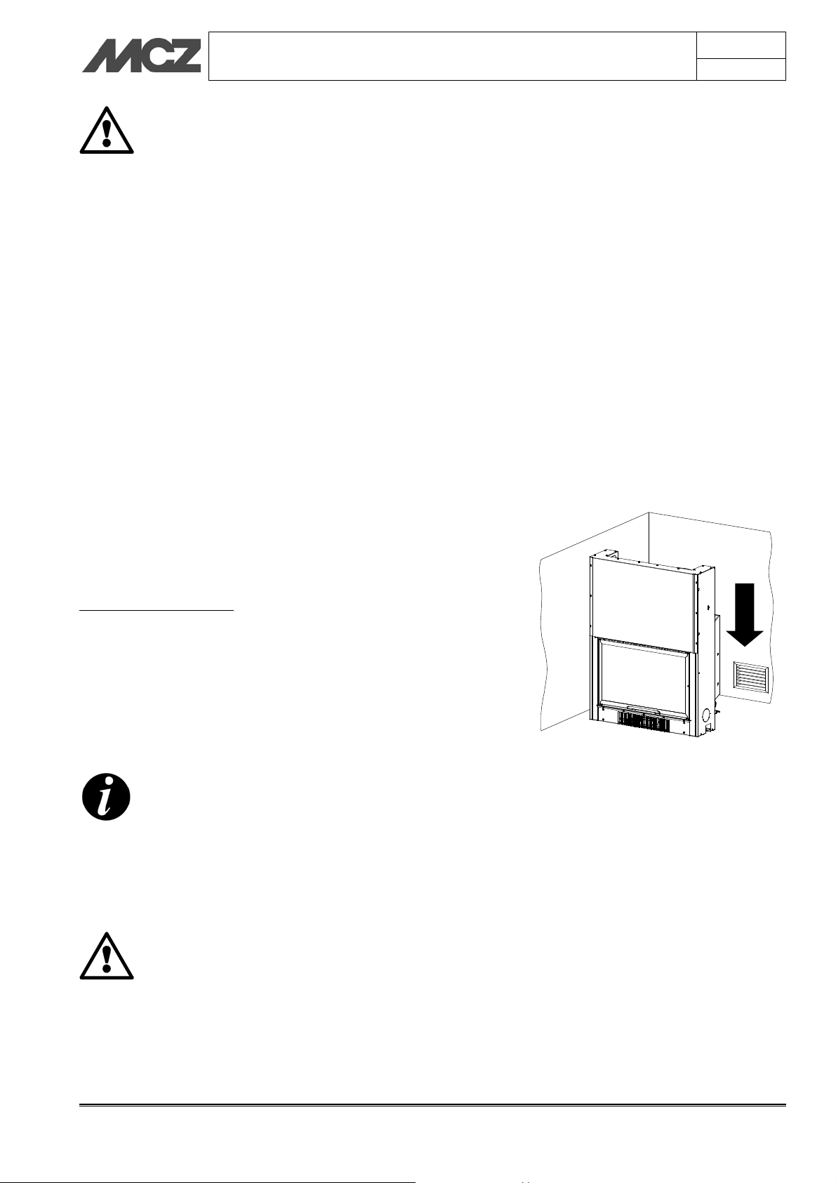
The Kits are installed in a vertical position as in the
images reported below in a way that the air vents
can work correctly.
Chapter 4
page
33
4.9.1. Kit 1 OPEN TANK
(Code MCZ 4015008022C)
1) Sheet metal support
2) Circulator
3) Non-return valve 1.5”
4) 3-way valve
5) Non-return valve ¾”
6) Flow switch
7) Vent valve
8) Domestic hot water exchanger
9) Electrical branching box
A) Aqueduct delivery ½”
B) Fireplace stove return ¾”
C) Fireplace stove hot water exchanger outlet ½”
D) Fireplace stove delivery ¾”
E) System delivery ¾”
Installation and assembly Technical service – MCZ GROUP S.p.A. all rights reserved - Reproduction prohibited

4.9.2. Kit 2 OPEN TANK
(code MCZ 4015008023)
1) Sheet metal support
2) Circulator
3) Non-return valve 1.5”
4) Vent valve
5) Separation exchanger
6) Electrical branching box
A) System return ¾”
B) System delivery ¾”
C) Fireplace stove return ¾”
D) Fireplace stove delivery ¾”
INSTALLATION AND USE MANUAL
Chapter 4
page
34
4.9.3. Kit 3 OPEN TANK
(cod. MCZ 4015008024)
1) Sheet metal support
2) Circulator
3) Non-return valve 1.5”
4) Non-return valve ¾”
5) 3-way valve
6) Vent valve
7) Separation exchanger
8) Domestic hot water exchanger
9) Flow switch
10) Electrical branching box
A) System return ¾”
B) System delivery ¾”
C) Fireplace stove return ¾”
D) Fireplace stove delivery ¾”
E) Fireplace stove hot water exchanger outlet ½”
F) Boiler cold water exchanger delivery ½”
G) Aqueduct delivery ½”
Installation and assembly Technical service – MCZ GROUP S.p.A. all rights reserved - Reproduction prohibited

4.9.4. Kit 1 CLOSED TANK
(cod. MCZ 4015008025)
1) Sheet metal support
2) Circulator
3) Non-return valve 1.5”
4) Non-return valve ¾”
5) 3-way valve
6) Vent valve
7) Automatic vent
8) Safety valve
9) Expansion tank 6L
10) Electrical branching box
A) Fireplace stove return ¾”
B) Fireplace stove delivery ¾”
C) System delivery ¾”
D) Expansion tank ¾”
INSTALLATION AND USE MANUAL
Chapter 4
page
35
4.9.5. Kit 2 CLOSED TANK
(cod. MCZ 4015008026)
1) Sheet metal support
2) Circulator
3) Non-return valve 1.5”
4) Non-return valve ¾”
5) 3-way valve
6) Vent valve
7) Automatic vent
8) Safety valve
9) Expansion tank 6L
10) Electrical branching box
11) Flow switch
12) Domestic hot water exchanger
A) Aqueduct delivery ½”
B) Fireplace stove return ¾”
C) Fireplace stove hot water exchanger outlet ½”
D) Fireplace stove delivery ¾”
E) System delivery ¾”
F) Expansion tank ¾”
Installation and assembly Technical service – MCZ GROUP S.p.A. all rights reserved - Reproduction prohibited

INSTALLATION AND USE MANUAL
4.10. UNIT CLADDING
Only after finishing all the installation operations of
the fireplace stove, connecting the smoke duct,
electric and hydraulic connections and carrying out
the first lighting, is it possible to begin the cladding
of the unit
4.10.1. INSULATION OF FIREPLACE STOVE
The fireplace stove must also always be separated from nearby
walls and ceilings.
If necessary, use insulating materials to insulate the walls that are in
contact with the unit if they may be damaged or catch fire (walls made
of wood, plasterboard, etc.).
4.10.2. INSULATING A WOODEN BEAM
Chapter 4
page
36
The wood beam must be protected with adequate insulation from
heated parts to prevent the risk of fire or damage of the cladding.
4.10.3. Decorative hood
Before building the decorative hood we strongly recommend a
general test of the fireplace stove in order to correct any
operating problems or possible leaks of smoke into the room.
We recommend making the hood liner in fire-resistant
plasterboard of a 15/20 mm. thickness, with a self-supporting
frame in galvanised profile so as not to put weight on the components
of the cladding (such as wooden beams and marble architraves) that do
not have a load-bearing structure and to make it easy to work in the
event of future anomalies and/or maintenance.
min 1 cm
Installation and assembly Technical service – MCZ GROUP S.p.A. all rights reserved - Reproduction prohibited

INSTALLATION AND USE MANUAL
5. OPERATION
5.1. PRE-LIGHTING WARNINGS
Do not touch the fireplace stove when it is lit for the first
time. During this phase, the paint finishes drying and
hardens. If you touch the paint, you may expose the steel
surface.
It is good practice to provide plenty of ventilation in the
room during the initial lighting, as the stove will give off a
small amount of smoke and smell of paint.
If necessary, touch up the paint with the aerosol spray in
the original colour (see “Fireplace stove accessories and
inserts")
Do not stay near the fireplace stove, and as previously mentioned,
ventilate the room. The smoke and the smell of paint will vanish after
about one hour of operation. There are no health risks involved.
The fireplace stove will be subject to expansion and contraction during
the stages of lighting and cooling down, and may therefore make slight
creaking noises.
This phenomenon is absolutely normal, the structure being made of
sheet steel, and must not be considered a fault.
It is very important not to bring the stove up to full
heat immediately. Bring it up to temperature
gradually.
This avoids damages to welds and the steel
structure.
Do not demand full heating
performance straight away!
Chapter 5
page
37
5.2. OPERATING TEST
After having created all the electrical connections foreseen, we advise
testing the HYDROTHERM fireplace stove together with the installer.
Operation Technical service – MCZ GROUP S.p.A. all rights reserved - Reproduction prohibited

INSTALLATION AND USE MANUAL
Slowly fill the fireplace stove and the system only using
the open expansion tank (if included) through the
natural fall of water;
With the installation with the tank closed, fill the system
directly from the mains, setting a pressure, when cold,
of 1-1.5 bars and discharging any air bubbles in the
boiler and on the system.
Never light the fire if the system is not full of water; the
structure may be damaged.
While filling, open all the vents of the radiators and
those of the system; vent the air in the system that may
obstruct the circulation of water.
On the control panel or control unit set the start
temperature of the pump (see the instructions of the
control panel).
Place wood in small pieces that is well dried (humidity
15/20%). Light the fire without excessively overheating
the structure during the first lighting. Any odours from
manufacturing residue and/or evaporation will form the
first time lighting occurs, and will disappear after a
lighting at full power has occurred a few times.
Make sure you have read and completely understood the contents of
this instruction booklet.
Remove any components which might burn from the fireplace stove
and door (various instructions and adhesive labels).
Remove the stickers from the ceramic glass or the high temperature
could melt them and irreparably damage the glass. In this case, the
MCZ warranty does not cover the glass.
The HYDROTHERM fireplace stove can be placed in a corner or along a
wall. You can customize with MCZ claddings or install them during
construction with materials that are resistant to high temperatures.
THE CLADDING MAY ONLY BE INSTALLED AFTER
HYDRAULICALLY AND ELECTRICALLY CONNECTING
THE FIREPLACE STOVE AND HAVING TESTED ITS
FUNCTION AND HYDRAULIC SEAL
The fireplace stove and the parts of the cladding must be attached to
one another without coming into contact with the steel
structure to prevent transmission of the heat to the marble and/or
stone, and to allow normal thermal dilation. Use care with wood
finishes such as crossbeams or shelves.
It is advisable to create the hood of the cladding with plasterboard
panels. It is worthwhile to provide for an airtight inspection grille to
access the probe in case of malfunction.
Chapter 5
page
38
Operation Technical service – MCZ GROUP S.p.A. all rights reserved - Reproduction prohibited

INSTALLATION AND USE MANUAL
5.3. CHOICE OF FUEL
FUEL: Wood
To obtain the maximum performance from your HYDROSYSTEM
fireplace stove, it is of primary importance to use wood with suitable
characteristics.
It is advisable to use wood for heating such as oak, beech, locust
tree, or oak with good calorific energy, or logs of pressed wood that
do not have resin. These have a high calorific power and must
be used with caution to avoid overheating which could damage
the stove.
It is advisable to use fuels such as poplar, pine, lime tree, or
chestnut which have low calorific power, since they are soft wood and
also they do not burn for a long time.
Avoid using fuels such as pine, fir, and olive as they contain a high
degree of resin and their combustion may substantially soil the fire
mouth and the ceramic glass; also, they do not have an exceptional
yield.
For all types of wood listed, the humidity they contain is
essential because it determines the calorific energy.
Do not use treated fuels (such as painted or
varnished wood, or particle board) or unsuitable
materials (such as plastics and derivatives), which
could release toxic or polluting substances. Do not
burn rubbish.
The gases produced by combustion due the use of
unsuitable fuels cause damage to the fireplace stove
and the chimney, they cause pollution and can
compromise your health.
A high percentage of humidity produces condensation in the
smoke duct causing an alteration in the draught and
generating smoke and a significant deposit of soot on the
glass of the door and in the flue pipe with a possible risk of
a chimney fire later on.
At least once a month check that there are no creosote
deposits inside of the fire box and between the heater pipe;
if the surface is a shiny black and thick, IT SHOULD BE
CLEANED with the scraper provided or a similar tool.
Chapter 5
page
39
Wood drying
time (i.e. beech)
Freshly cut 50 /
3 months 40 2410
6 months 35 2700
9 months 30 2900
12 months 25 3150
15 months 20 3400
18 months 15 3710
21 months 10 3980
Figure 11 – Calorific energy (e.g. beech) in
relation to humidity contained.
humidity
%
Heat
power
Kcal/h
5.4. LOADING THE FUEL
For the loading of fuel, just open the door turning the handle upwards
as shown to the side.
During use, the metal parts and the glass reach high
temperatures, so it is necessary to use the special thermal
glove supplied.
During use it is also necessary to keep the door completely lowered
since intermediate positions cause abnormal combustion (forge effect),
with a consequent rapid consumption of wood and a drastically reduced
yield to the boiler.
Operation Technical service – MCZ GROUP S.p.A. all rights reserved - Reproduction prohibited

INSTALLATION AND USE MANUAL
For cooking food on the grille, we advise first forming a bed of coals
without flames and then opening the door only to turn the food on the
grille.
5.5. CONTROL OF COMBUSTION
PRIMARY AIR
The fireplace stove is provided, at the front, with a safety mechanical
valve that adjusts the entrance of primary air depending on the
temperature of the water in the hottest point of the boiler. The valve
stays open until 40 C°; once this threshold is exceeded it gradually
begins to close as the temperature increases, until completely
obstructing the passage of air at approximately 80 C°. This is necessary
to avoid that the water in the boiler overheats and reduce unnecessary
consumption of fuel. (Fig.A)
SECONDARY AIR
The emission of secondary air is predetermined; it is necessary to
partially clean the glass of the firebox door and allows the completion
of the combustion process by lowering the percentage of CO in the
smoke and improving the yield of the product. (Fig. B and B1)
The use of damp or treated wood emits a higher quantity of
smoke than normal that can dirty glass faster. Also the low
performance of the flue pipe can jeopardise glass cleanliness
since smoke remains in the combustion chamber longer than
normal.
Figura A
Chapter 5
page
40
80°
40°
5.6. FIRST LIGHTING
It is advisable to approach the first lighting with caution, using
good-quality, well-seasoned wood.
The primary air inlet must be fully open. Do not use alcohol,
petrol, or other volatile flammable substances. On first lighting,
fumes and unpleasant smells may be given off, caused by the drying of
the product; this is not hazardous, and it is sufficient to ventilate the
room. Once combustion has started, pieces of wood of normal size may
be added.
The flame must have as far as possible a smooth and laminar flow. On
the various occasions when the stove needs reloading, the
door should be opened slowly, to avoid blowbacks of smoke
into the room.
Proceed as follows:
Place a small amount of balled paper in the stove.
Cover the paper with a small quantity of twigs and a few pieces of
wood.
Light the paper, and if necessary leave the door up.
When the twigs are burning, the door can be closed.
As the fire burns, add wood. Never overload the fireplace stove
with wood (see technical specifications in the table).
As soon as the flames have died down and a bed of embers has
formed, load the stove normally. Small loads of wood are preferable to
large ones for combustion.
Figura B
Figura B1
Operation Technical service – MCZ GROUP S.p.A. all rights reserved - Reproduction prohibited

INSTALLATION AND USE MANUAL
Chapter 5
page
41
Attention
Do not use volatile, flammable substances
(petrol, alcohol etc.) for lighting the fire.
Do not use fuels which could release toxic
substances or pollutants.
Do not put the fire out by throwing water on it.
Check the external and internal air intakes, and
the flue pipe, at least once a year, arranging for
them to be cleaned.
During use, the metal parts and the glass reach
high temperatures. For all jobs of loading the
stove, adjustment or cleaning the ash drawer,
use the insulating glove provided.
Never leave children unattended near the
fireplace stove when it is in use.
The risk of burns from contact with hot surfaces
is very high.
5.7. EMERGENCY SITUATIONS
If for any reason the stove fire needs to be suddenly and quickly put
out or a fire in the flue pipe needs to be put out, proceed as follows:
The equipment door must be kept closed.
Disconnect the power supply and do not use water (shock
hazard).
Urgently request the intervention of the competent authorities.
Operation Technical service – MCZ GROUP S.p.A. all rights reserved - Reproduction prohibited

INSTALLATION AND USE MANUAL
6. MAINTENANCE AND CLEANING
Chapter 6
page
42
ATTENTION!
All cleaning operations of all parts should be
conducted with the fireplace stove cold.
6.1. CLEANING TO BE PERFORMED BY THE USER
6.1.1. Cleaning the glass
Specific products can be used to clean the glass (see our pricelist), a
cloth dampened with water and ammonia or a bit of white ash and a
newspaper.
Completely lower the door and using the suitable hook provided or your
hands, open the handle (1) taking it from position A to B, thus locking
the door frame. Insert the hexagonal key provided in the lock and turn
it anticlockwise (2) to open the door (3). To close, perform the steps
listed above in reverse order.
ATTENZIONE!
Do not use abrasive products and do not spray the
cleaning product on the painted parts or on the
gaskets of the door (ceramic fibre cord)
1
3
2
A
B
Detail of handle for opening flap door
A – CLOSED POSITION
B – OPEN POSITION
6.1.2. Cleaning the exchanger
A scraper is provided to remove the creosote that may form in the
exchanger; when the fireplace stove is cold the creosote is black, shiny,
flaky and easy to remove. The advice is to remove the creosote at least
every 20 days of operation to always have a constant yield over time;
the exchanger pipe will only require a general brushing.
This operation is very important and easy to do in order to obtain the
declared efficiency over time. With the exchanger blocked with
creosote, 20% of the efficiency may be lost.
6.1.3. Cleaning out the ashes
This operation should be performed with the fireplace stove off.
Adequate ash drawer cleaning is also recommended for correct
combustion.
ATTENTION!
If the ash drawer is not periodically emptied, deformations on
the grilles of the firebox bed may occur.
Ashes which are still hot must neither be dumped outside in an
uncontrolled manner nor put in the dustbin. Leave them to cool
down in the open air in a metal container or far from
combustible materials.
Scraper for the cleaning of the exchanger
Maintenance and cleaning Technical service – MCZ GROUP S.p.A. all rights reserved - Reproduction prohibited

INSTALLATION AND USE MANUAL
6.1.4. Cleaning flue pipe
Mechanical cleaning of the flue pipe is recommended at least once a
year. Excessive deposits of unburnt solid material can cause problems
with the evacuation of smoke, and gives rise to a risk of chimney fires
6.1.5. Lubrication and routine maintenance of the
extensible guides
All of the doors of the fireplace stoves are mounted on extensible
ballbearing guides that ensure a robust, sturdy system that provides
silent movement.
Prolonged use and the heat of the fireplace stove gradually depletes
the lubricant in the guides. This will cause them to become less efficient
and noisier.
If necessary, periodically grease both runners as follows:
Pull open the frame liner and extract the door so you can see
the tracks of the guide.
Using the provided grease gun, apply two drops of grease,
about 5 mm in diameter, at the highest visible point of the
runners. Do not exceed the recommended amount!
Perform this operation on both guides. Keep in mind that the
total amount of grease to be used is about 0.5ml (see
graduated scale on grease gun).
After lubrication:
Put the glue gun back and conserve it
Lower and raise the door completely at least 6 or 7 times so
that the grease is spread onto all of the other components of
the guides to complete lubrication. You should notice a
substantial improvement in ease of movement and noise
reduction.
It is advisable to carry out this operation at the end of
the season of use, or whenever the runners become
too noisy.
Do not use other types of grease. If the grease gun
runs out, request an MCZ original replacement.
Chapter 6
page
43
Figure 15 – Points to be greased with provided
grease gun
Maintenance and cleaning Technical service – MCZ GROUP S.p.A. all rights reserved - Reproduction prohibited

INSTALLATION AND USE MANUAL
Chapter 7
page
44
7. DOOR ADDITIONAL WEIGHT KIT
7.1. Supplementary weight kits for door closure (only available for closed tank
version)
A supplementary weight kit is available as an accessory to be fixed
above the door; with this system the door lowers automatically when
released.
To fix the weight (P), open the door, insert the piece (as in figure) and
fit it on the C-shaped profile (S), then tigthen the 4 screws (K).
P
K
S
Door additional weight kit Technical service – MCZ GROUP S.p.A. all rights reserved - Reproduction prohibited

MCZ GROUP S.p.A.
Via La Croce 8
33074 Vigonovo di Fontanafredda (PN) – ITALY
Telephone: +39 0434/599599 PBX
Fax: +39 0434/599598
Internet: www.mcz.it
e-mail: mcz@mcz.it
8901158500 Rev. 0 09/2011
 Loading...