


INSTALLATION AND USE MANUAL
GAUGUIN
Index
page
1
INTRODUCTION....................................................................................................................................2
1. WARNINGS AND WARRANTY CONDITIONS .....................................................................................3
1.1. SAFETY WARNINGS........................................................................................................................3
1.2. GUARANTEE CONDITIONS ..............................................................................................................3
1.2.1. Exclusions................................................................................................................................3
2. GAUGUIN CLADDING WITH FIREPLACE STOVES FPURO95..............................................................5
3. ASSEMBLY OF GAUGUIN CLADDING.................................................................................................6
3.1. COMPONENTS OF GAUGUIN CLADDING FORMA PURO95...................................................................6
3.2. PHASE 1 - POSITIONING OF FIREPLACE STOVE FORMA PURO 95 ......................................................7
3.3. PHASE 2 – ASSEMBLY OF LOWER PROFILE AND SIDESRH/LH............................................................8
3.4. PHASE 3 – INSTALLATION OF UPPER PROFILE ...............................................................................10
3.5. PHASE 3 – WALL FOR RECESSED INSTALLATION............................................................................11
3.6. PHASE 4– ASSEMBLY OF SLATE FRAME WITH STAINLESS STEEL FIRE BOX......................................12
3.7. PHASE 5 – FINAL ASSEMBLY OF SLATE FRAME AND STAINLESS STEEL FIRE BED..............................14
3.8. TECHNICAL TERMS GLOSSARY OF THE PICTURES ..........................................................................16
Index Technical service – all rights reserved by mcz spa
Reproduction prohibited

INSTALLATION AND USE MANUAL
GAUGUIN
INTRODUCTION
Dear Customer,
thank you for choosing a MCZ product and in particular the Gauguin
cladding Forma Puro95.
We are sure that, by using it, you will appreciate the quality of an
accurately designed and tested product. Our goal is to combine
technology with easy of use and, above all, safety.
For optimal functioning of the Gauguin cladding and to fully
enjoy the heat and sense of well being that will spread
throughout your home, we suggest that you carefully read this
use and maintenance manual before using the product for the
first time; please contact your dealer should you require
assistance in resolving any doubts or problems.
Congratulations on your choice and remember, the fireplace stove
MUST NEVER be used by children who should always be kept at a
safe distance!
Introduction
page
2
Revisions to the publication
In order to improve the product, the Manufacturer reserves the right to
modify and update this publication without prior notice.
Reproduction, even partial, of this manual without the Manufacturer's
authorisation is prohibited.
Manual preservation.
• Please take care of this manual and keep it in a place that can be
quickly and easily reached.
• If this manual should be lost or destroyed, or if it is in poor
condition, request a copy from your dealer or directly from the
manufacturer, providing product identification data.
Introduction Technical service – all rights reserved by mcz spa
Reproduction prohibited
INSTALLATION AND USE MANUAL
GAUGUIN
1. WARNINGS AND WARRANTY CONDITIONS
1.1. SAFETY WARNINGS
• Check the conditions of the surface that will support the
weight of the stove. If it is made of flammable material
(such as wood, carpet, or plastic) provide suitable
insulation.
• The user is fully liable for improper product use,
releasing MCZ from any civil or penal liabilities.
• Any tampering with the fireplace stove, or use of nonoriginal spare parts, may be hazardous to the user and
releases MCZ from any civil or penal liability.
• Incorrect installation or poor maintenance (not
compliant with the provisions of this manual) may cause
damages to persons, animals or property. MCZ is not
civilly or criminally liable in these cases.
Chapter 1
page
3
1.2. GUARANTEE CONDITIONS
MCZ guarantees the product, with the exception for the elements
subject to normal wear listed below, for two years from the date of
purchase that is proven by a document that indicates the dealer's name
and date of sale, if the completed warranty certificate was returned
within 8 days and if the product was installed and inspected by a
specialised installation technician and according to the detailed
instructions indicated in the instruction manual supplied with the
product.
The warranty includes the free replacement or repair of parts
recognised as factory defective.
1.2.1. Exclusions
The guarantee does not cover any part that may be defective
due to negligence or careless use, incorrect maintenance,
installation non compliant with that specified by MCZ.
MCZ refuses to accept any responsibility for any damage which may be
caused, directly or indirectly, by persons, animals or things as a result
of the failure to observe all the provisions set forth in the instruction
booklet, especially those concerning warnings on the subject of
installation, use and maintenance of the appliance.
In the event of product inefficiency, please contact your dealer and/or
area importer.
Damages caused by transport and handling are not covered by the
guarantee.
Exclusively refer to the supplied manual for product installation and
use.
The guarantee will be invalidated in the event of damage caused by
tampering with the appliance, atmospheric agents, natural disasters,
Chapter 1 Technical service – all rights reserved by mcz spa
Reproduction prohibited
INSTALLATION AND USE MANUAL
GAUGUIN
electrical discharges, fire and lack of, or incorrect, maintenance in
terms of the manufacturer's instructions.
REQUEST FOR SERVICE
Requests for service must be addressed to the dealer
who shall forward the request to the MCZ technical
assistance service.
MCZ is not liable in the event the product and any
other accessory is improperly used or modified
without authorisation.
Only original MCZ spare parts must be used for all
replacements.
Chapter 1
page
4
Chapter 1 Technical service – all rights reserved by mcz spa
Reproduction prohibited
INSTALLATION AND USE MANUAL
GAUGUIN
Chapter 2
page
5
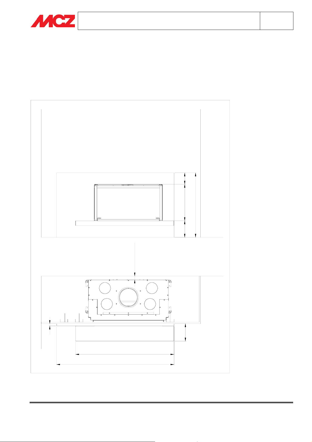
2. GAUGUIN CLADDING WITH FIREPLACE STOVES FPURO95
The Gauguin model is a recessed cladding, i.e. the fireplace stove is recessed into the wall. Therefore it is
necessary to build a counter-wall that protrudes from the perimeter wall. The depth of the wall to be constructed
is at your discretion provided you comply with all safety distances for the fireplace stove. For this purpose please
refer to the
Manual for Installation and Use
of Forma Puro FP95.
30
850
218 482 150
DISTANZA
DI SICUREZZA
230
1300
1550
Chapter 2 Technical service – all rights reserved by mcz spa
Reproduction prohibited
INSTALLATION AND USE MANUAL
GAUGUIN
3. ASSEMBLY OF GAUGUIN CLADDING
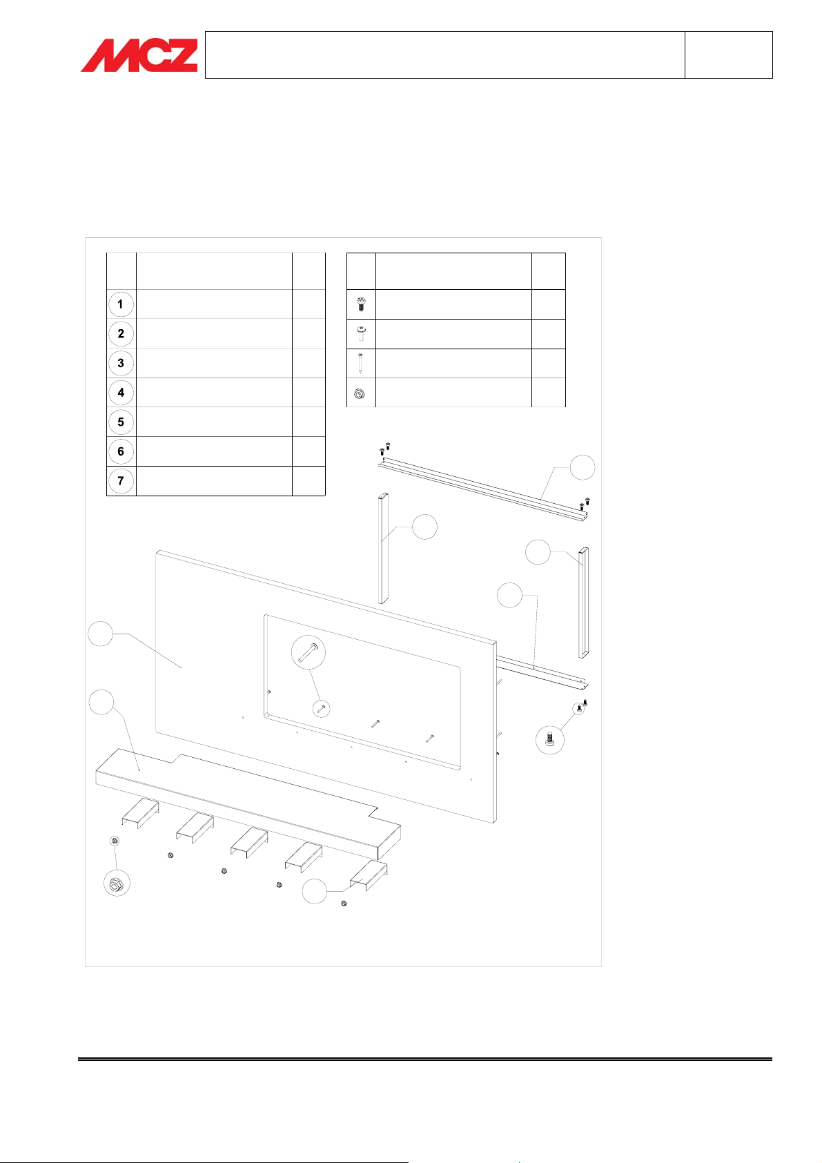
3.1. COMPONENTS OF GAUGUIN CLADDING FORMA PURO95
Chapter 3
page
6
COMPONENTE
PROFILO INFERIORE
SPALLA SX
SPALLA DX
PROFILO SUPERIORE
STAFFA PIANO FUOCO 5
5
N.
1
1
1
1
1CORNICE ARDESIA
1PIANO FUOCO
VITERIA IN DOTAZIONE
VITE PH-AB 3,9X9,5
VITE AUTOPERF.4.2X16
VITE M5X50 C/FLANGIA
DADO FLANGIATO FD M5
2
N.
8
2
5
5
4
3
1
6
7
Chapter 3 Technical service – all rights reserved by mcz spa
Reproduction prohibited

INSTALLATION AND USE MANUAL
GAUGUIN
Chapter 3
page
7
3.2. PHASE 1 - POSITIONING OF FIREPLACE STOVE FORMA PURO 95
Place the Forma Puro95 in the desired position and at a safe distance from the rear wall. Raise the
fireplace stove so that the height of the edge-cover profile with respect to the floor is 220 mm. A second
adjustment of the unit, if necessary, is made during assembly of the cladding.
N.B. There are various ways of raising the Forma Puro95, at your discretion. However, any solution
must ensure safety and stability of the unit.
Install the unit Forma Puro 95 in accordance with the instructions in the respective
and run a quick test for proper operation. If the test is successful, you can install the Gauguin cladding.
Use
PROFILO
COPRIBORDO
Manual for Installation and
220
DISTANZA
DI SICUREZZA
PAVIMENTO
BASE APPOGGIO
FORMA PURO
Chapter 3 Technical service – all rights reserved by mcz spa
Reproduction prohibited

INSTALLATION AND USE MANUAL
GAUGUIN
Chapter 3
page
8
3.3. PHASE 2 – ASSEMBLY OF LOWER PROFILE AND SIDESRH/LH
Fasten the elements using 4 screws PH-AB 3.9X95. Make sure the sides are installed facing the right way, i.e.
with the outlet at the top and facing inwards (towards the fireplace stove).
Move the three assembled elements near the unit so that the lower profile is positioned under the edge-cover
profile of the Forma Puro95.
The slots of the lower profile must be aligned with those of the edge-cover profile Forma Puro95. Fasten the
assembly to the unit using the same screws that support the profile of the fireplace stove.
Chapter 3 Technical service – all rights reserved by mcz spa
Reproduction prohibited

COPRIBORDO
FORMA PURO95
PROFILO
INSTALLATION AND USE MANUAL
GAUGUIN
Chapter 3
page
9
PROFILO
COPRIBORDO
FORMA PURO95
PROFILO INFER.
GAUGUIN
Chapter 3 Technical service – all rights reserved by mcz spa
Reproduction prohibited

INSTALLATION AND USE MANUAL
GAUGUIN
3.4. PHASE 3 – INSTALLATION OF UPPER PROFILE
Chapter 3
page
10
VITE AUTOPERF. 4.2X16
VITE AUTOPERF. 4.2X16
Fasten the upper element (4) to the right/left sides using 4 screws PH-AB 3.9X95 and to Forma Puro95 with 2
self-tapping screws. 4.2X16. When assembly is complete, the structure thus assembled must be rigid and firmly
attached to the fireplace stove.
Chapter 3 Technical service – all rights reserved by mcz spa
Reproduction prohibited

INSTALLATION AND USE MANUAL
GAUGUIN
Chapter 3
page
11
3.5. PHASE 3 – WALL FOR RECESSED INSTALLATION
Prepare the wall for recessed installation using fireproof material, such as fireproof plasterboard, and at least 3
steel uprights. For greater safety, you can use 6 uprights, inserted two by two). Provide an opening of 1060X570
mm, 160 mm from the floor (see drawing). The steel uprights must be placed vertically in the positions shown
(see drawing).
MONTANTE ACCIAIO
290
CENTRO
MONTANTE
90
CENTRO
MONTANTE
MONTANTE
ACCIAIO
FILO FORO
570160
1060
Chapter 3 Technical service – all rights reserved by mcz spa
Reproduction prohibited

INSTALLATION AND USE MANUAL
GAUGUIN
Chapter 3
page
3.6. PHASE 4– ASSEMBLY OF SLATE FRAME WITH STAINLESS STEEL FIRE BOX
12
Insert the stainless steel fire box (6) in the slate frame (5), lowering it enough that the holes of the fire bed are
concentric with those of the slate frame. Add two brackets (7), ensuring that the fire bed rests on the brackets.
Fasten the three elements (slate frame, fire bed and bracket) using 2 screws M5X50 w/flange (which pass
through from the back to the front side), secured with two flanged nuts FD M5.
LATO A VISTA
Chapter 3 Technical service – all rights reserved by mcz spa
Reproduction prohibited

INSTALLATION AND USE MANUAL
GAUGUIN
Chapter 3
page
13
The right side of the fire bed must be flush with the right side of the frame, looking at the door of the Forma
Puro 95 and sides towards the centre of the room.
Add the other brackets, also adherent to the fire bed, and fastened with screw M5 and flanged nut M5.
Chapter 3 Technical service – all rights reserved by mcz spa
Reproduction prohibited

INSTALLATION AND USE MANUAL
GAUGUIN
Chapter 3
page
14
CORNICE
ARDESIA
850
SEZIONE AA
PIANO
FUOCO
STAFFA
50
3.7. PHASE 5 – FINAL ASSEMBLY OF SLATE FRAME AND STAINLESS STEEL FIRE
BED
Chapter 3 Technical service – all rights reserved by mcz spa
Reproduction prohibited

INSTALLATION AND USE MANUAL
GAUGUIN
Chapter 3
page
15
Move the assembled cladding near FormaPuro95. Perforate the wall for recessed insertion at the threaded bars
on the rear side of the slate frame. Secure from the inside with the same number of flanged nuts M5.
Chapter 3 Technical service – all rights reserved by mcz spa
Reproduction prohibited

INSTALLATION AND USE MANUAL
GAUGUIN
3.8. TECHNICAL TERMS GLOSSARY OF THE PICTURES
PAGE 5 PAGE 5
DISTANZA DI SICUREZZA SAFETY DISTANCE
PAGE 6 PAGE 6
COMPONENTE COMPONENT
PROFILO INFERIORE LOWER PROFILE
SPALLA SX LH SIDE
SPALLA DX RH SIDE
PROFILO SUPERIORE UPPER PROFILE
CORNICE ARDESIA SLATE FRAME
PIANO FUOCO FIRE BED
STAFFA PIANO FUOCO FIRE BED BRACKET
VITERIA IN DOTAZIONE NUTS AND BOLTS PROVIDED
VITE PH-HB 3,5X9,5 SCREW PH-HB 3.5X9.5
VITE AUTOPERFORANTE PANEL 4,2X16 PANEL SELF-TAPPING SCREW 4.2X16
VITE M5X50 C/FLANGIA SCREW M5X50 W/FLANGE
DADO FLANGIATO FD M5 FLANGED NUT FD M5
PAGE 7 PAGE 7
PROFILO COPRIBORDO EDGE-COVER PROFILE
PAVIMENTO FLOOR
DISTANZA DI SICUREZZA SAFETY DISTANCE
BASE APPOGGIO FORMA PURO SUPPORT BASE FORMA PURO
PAGE 9 PAGE 9
PROFILO COPRIBORDO FORMA PURO65 EDGE-COVER PROFILE FORMA PURO65
PROFILO INFERIORE GAUGUIN GAUGUIN LOWER PROFILE
PAGE 10 PAGE 10
VITE AUTOPERFORANTE PANEL 4,2X16 PANEL SELF-TAPPING SCREW 4.2X16
PAGE 11 PAGE 11
MONTANTE ACCIAIO STEEL UPRIGHT
CENTRO MONTANTE UPRIGHT CENTRE
MONTANTE ACCIAIO FILO FORO STEEL UPRIGHT FLUSH WITH HOLE
PAGE 13 PAGE 13
LATO A VISTA VISIBLE SIDE
Glossary
page
16
Glossary Technical service – all rights reserved by mcz spa
Reproduction prohibited

INSTALLATION AND USE MANUAL
GAUGUIN
PAGE 14 PAGE 14
CORNICE ARDESIA SLATE FRAME
PIANO FUOCO FIRE BED
STAFFA BRACKET
SEZIONE AA SECTION A-A
Glossary
page
17
Glossary Technical service – all rights reserved by mcz spa
Reproduction prohibited
 Loading...